EP3923254A1 - Money handling apparatus, money handling system and money handling method - Google Patents
Money handling apparatus, money handling system and money handling method Download PDFInfo
- Publication number
- EP3923254A1 EP3923254A1 EP21178759.3A EP21178759A EP3923254A1 EP 3923254 A1 EP3923254 A1 EP 3923254A1 EP 21178759 A EP21178759 A EP 21178759A EP 3923254 A1 EP3923254 A1 EP 3923254A1
- Authority
- EP
- European Patent Office
- Prior art keywords
- cassette
- money
- coin
- handling apparatus
- unit
- Prior art date
- Legal status (The legal status is an assumption and is not a legal conclusion. Google has not performed a legal analysis and makes no representation as to the accuracy of the status listed.)
- Granted
Links
Images



Classifications
-
- G—PHYSICS
- G07—CHECKING-DEVICES
- G07D—HANDLING OF COINS OR VALUABLE PAPERS, e.g. TESTING, SORTING BY DENOMINATIONS, COUNTING, DISPENSING, CHANGING OR DEPOSITING
- G07D11/00—Devices accepting coins; Devices accepting, dispensing, sorting or counting valuable papers
- G07D11/20—Controlling or monitoring the operation of devices; Data handling
- G07D11/24—Managing the inventory of valuable papers
- G07D11/245—Replenishment
-
- G—PHYSICS
- G06—COMPUTING OR CALCULATING; COUNTING
- G06Q—INFORMATION AND COMMUNICATION TECHNOLOGY [ICT] SPECIALLY ADAPTED FOR ADMINISTRATIVE, COMMERCIAL, FINANCIAL, MANAGERIAL OR SUPERVISORY PURPOSES; SYSTEMS OR METHODS SPECIALLY ADAPTED FOR ADMINISTRATIVE, COMMERCIAL, FINANCIAL, MANAGERIAL OR SUPERVISORY PURPOSES, NOT OTHERWISE PROVIDED FOR
- G06Q20/00—Payment architectures, schemes or protocols
- G06Q20/08—Payment architectures
- G06Q20/20—Point-of-sale [POS] network systems
-
- G—PHYSICS
- G07—CHECKING-DEVICES
- G07D—HANDLING OF COINS OR VALUABLE PAPERS, e.g. TESTING, SORTING BY DENOMINATIONS, COUNTING, DISPENSING, CHANGING OR DEPOSITING
- G07D11/00—Devices accepting coins; Devices accepting, dispensing, sorting or counting valuable papers
- G07D11/10—Mechanical details
- G07D11/12—Containers for valuable papers
-
- G—PHYSICS
- G07—CHECKING-DEVICES
- G07D—HANDLING OF COINS OR VALUABLE PAPERS, e.g. TESTING, SORTING BY DENOMINATIONS, COUNTING, DISPENSING, CHANGING OR DEPOSITING
- G07D11/00—Devices accepting coins; Devices accepting, dispensing, sorting or counting valuable papers
- G07D11/10—Mechanical details
- G07D11/12—Containers for valuable papers
- G07D11/13—Containers for valuable papers with internal means for handling valuable papers
-
- G—PHYSICS
- G07—CHECKING-DEVICES
- G07D—HANDLING OF COINS OR VALUABLE PAPERS, e.g. TESTING, SORTING BY DENOMINATIONS, COUNTING, DISPENSING, CHANGING OR DEPOSITING
- G07D11/00—Devices accepting coins; Devices accepting, dispensing, sorting or counting valuable papers
- G07D11/10—Mechanical details
- G07D11/14—Inlet or outlet ports
-
- G—PHYSICS
- G07—CHECKING-DEVICES
- G07D—HANDLING OF COINS OR VALUABLE PAPERS, e.g. TESTING, SORTING BY DENOMINATIONS, COUNTING, DISPENSING, CHANGING OR DEPOSITING
- G07D11/00—Devices accepting coins; Devices accepting, dispensing, sorting or counting valuable papers
- G07D11/20—Controlling or monitoring the operation of devices; Data handling
- G07D11/22—Means for sensing or detection
- G07D11/23—Means for sensing or detection for sensing the quantity of valuable papers in containers
-
- G—PHYSICS
- G07—CHECKING-DEVICES
- G07D—HANDLING OF COINS OR VALUABLE PAPERS, e.g. TESTING, SORTING BY DENOMINATIONS, COUNTING, DISPENSING, CHANGING OR DEPOSITING
- G07D11/00—Devices accepting coins; Devices accepting, dispensing, sorting or counting valuable papers
- G07D11/20—Controlling or monitoring the operation of devices; Data handling
- G07D11/30—Tracking or tracing valuable papers or cassettes
-
- G—PHYSICS
- G07—CHECKING-DEVICES
- G07D—HANDLING OF COINS OR VALUABLE PAPERS, e.g. TESTING, SORTING BY DENOMINATIONS, COUNTING, DISPENSING, CHANGING OR DEPOSITING
- G07D11/00—Devices accepting coins; Devices accepting, dispensing, sorting or counting valuable papers
- G07D11/60—User-interface arrangements
-
- G—PHYSICS
- G07—CHECKING-DEVICES
- G07D—HANDLING OF COINS OR VALUABLE PAPERS, e.g. TESTING, SORTING BY DENOMINATIONS, COUNTING, DISPENSING, CHANGING OR DEPOSITING
- G07D3/00—Sorting a mixed bulk of coins into denominations
- G07D3/14—Apparatus driven under control of coin-sensing elements
-
- G—PHYSICS
- G07—CHECKING-DEVICES
- G07D—HANDLING OF COINS OR VALUABLE PAPERS, e.g. TESTING, SORTING BY DENOMINATIONS, COUNTING, DISPENSING, CHANGING OR DEPOSITING
- G07D9/00—Counting coins; Handling of coins not provided for in the other groups of this subclass
-
- G—PHYSICS
- G07—CHECKING-DEVICES
- G07F—COIN-FREED OR LIKE APPARATUS
- G07F19/00—Complete banking systems; Coded card-freed arrangements adapted for dispensing or receiving monies or the like and posting such transactions to existing accounts, e.g. automatic teller machines
- G07F19/20—Automatic teller machines [ATMs]
- G07F19/202—Depositing operations within ATMs
-
- G—PHYSICS
- G07—CHECKING-DEVICES
- G07F—COIN-FREED OR LIKE APPARATUS
- G07F19/00—Complete banking systems; Coded card-freed arrangements adapted for dispensing or receiving monies or the like and posting such transactions to existing accounts, e.g. automatic teller machines
- G07F19/20—Automatic teller machines [ATMs]
- G07F19/203—Dispensing operations within ATMs
-
- G—PHYSICS
- G07—CHECKING-DEVICES
- G07F—COIN-FREED OR LIKE APPARATUS
- G07F5/00—Coin-actuated mechanisms; Interlocks
- G07F5/24—Coin-actuated mechanisms; Interlocks with change-giving
Definitions
- the present disclosure relates to a money handling apparatus, a money handling system, and a money handling method.
- Patent Literatures (hereinafter, "Patent Literature” will be referred to as "PTL”) 1 and 2).
- PTL 1 discloses a cash handling apparatus. This apparatus deposits a coin, which has been collected from a cash settlement apparatus, from a cash transport cassette attached to an upper portion of the cash handling apparatus, and dispenses a coin, with which the cash settlement apparatus is replenished, into a cash transport cassette attached to a lower portion of the cash handling apparatus.
- PTL 2 discloses a concurrent handling system of depositing proceeds from sales and dispensing a change fund.
- Such a system counts collected money, which is collected from a change payment machine and which comprises proceeds from sales for the day, and adjusts a change fund for the succeeding business day, with which the change payment machine is replenished, by a difference between the change fund for the succeeding business day and a deposited amount for the day.
- This system prepares the change fund for the succeeding business day by appropriating the change fund for the succeeding business day from the collected money for the day and by performing replenishment of a shortage, which cannot be appropriated from the collected money for the day, from a storage unit.
- PTL 1 describes a coin handling apparatus to which a cash transport cassette is attached at two positions of the coin handling apparatus, but does not disclose a specific operation method of depositing and dispensing using the cash transport cassette. Further, in the technique of PTL 2, the change fund for the succeeding business day is prepared after counting cash collected from the change payment machine and performing predetermined processing so that an operator has to wait during that period and the working efficiency may decrease.
- An object of the present disclosure is to provide a money handling apparatus, a money handling system, and a money handling method that are capable of shortening a waiting time for a change fund to be dispensed.
- a money handling apparatus of the present disclosure comprises: a housing; a first cassette attachment unit and a second cassette attachment unit that are provided in the housing; a first transport unit that performs a depositing processing to deposit money from a first cassette, attached to the first cassette attachment unit, into the housing; a second transport unit that performs a dispensing processing to dispense money from the housing as a change fund into a second cassette that is attached to the second cassette attachment unit; and processing circuitry configured to control the first transport unit and control the second transport unit such that the dispensing processing of the change fund is performed before the depositing processing of the money.
- the processing circuitry may control the first transport unit and the second transport unit such that the dispensing processing of the change fund into the third cassette is performed.
- the processing circuitry may control the first transport unit and the second transport unit such that the depositing processing of the money from the first cassette starts after the dispensing processing of the change fund into the second cassette and the dispensing processing of the change fund into a third cassette attached to the second cassette attachment unit in place of the second cassette are performed.
- the processing circuitry may control the second transport unit such that the change fund is dispensed in a money quantity for each denomination that is set in advance.
- the processing circuitry may control the second transport unit such that the change fund is dispensed in an amount based on the increase instruction.
- the money handling apparatus may further comprise identification circuitry configured to identify whether an operator is an authorized person allowed to increase the change fund, and in a case where the operator is identified as the authorized person, the processing circuitry may receive the increase instruction issued by the operator, and in a case where the operator is not identified as the authorized person, the processing circuitry may not receive the increase instruction issued by the operator.
- the first cassette attached to the first cassette attachment unit and the second cassette attached to the second cassette attachment unit may be each a money transport cassette comprising an opening which opens when the money transport cassette is attached to a specific apparatus, where the money transport cassette is configured to give or receive the money to or from the specific apparatus via the opening.
- the processing circuitry may control the first transport unit and the second transport unit such that proceeds from sales are deposited into the housing and that the change fund is dispensed into the second cassette, where the proceeds from sales are collected into the first cassette by a first commercial product registration apparatus, and the change fund is used in a second commercial product registration apparatus.
- the processing circuitry may control the second transport unit such that timing information on a timing of performing the dispensing processing of the change fund before the depositing processing of the money is acquired, and that the dispensing processing of the change fund is performed at the timing based on the timing information.
- a money handling system of the present disclosure comprises: the money handling apparatus described above; and a monitoring apparatus communicably connected to the money handling apparatus.
- the monitoring apparatus includes: an operation status grasping unit that grasps an operation status of the money handling apparatus; and circuitry configured to determine the timing of performing the dispensing processing of the change fund before the depositing processing of the money, based on the operation status grasped by the operation status grasping unit; and transmit timing information of the timing to the money handling apparatus.
- the processing circuitry may control the second transport unit such that the dispensing processing of the change fund is performed at the timing based on the timing information transmitted from the circuitry of the monitoring apparatus.
- a money handling method of the present disclosure comprises: dispensing money from housing of a money handling apparatus as a change fund into a second cassette that is attached to the money handling apparatus; depositing money from a first cassette attached to the money handling apparatus into the housing of the money handling apparatus; and controlling the money handling apparatus to depositing after the dispensing has ended.
- the money handling method may further comprise dispensing, in a case that a third cassette is attached to the money handling apparatus in place of the second cassette while the money in the first cassette is deposited, the money in the money handling apparatus as the change fund into the third cassette.
- the money handling method may further comprise dispensing, in a case that a third cassette is attached to the money handling apparatus in place of the second cassette after the processing of dispensing the change fund into the second cassette ends and before processing of depositing the money in the first cassette starts, the money in the money handling apparatus as the change fund into the third cassette.
- the money handling method may further comprise dispensing, in a case where the change fund is dispensed, the change fund in a money quantity for each denomination that is set in advance.
- the money handling method may further comprise dispensing the change fund in an amount based on an increase instruction when the increase instruction is received from an operator, where the increase instruction is an instruction to increase the change fund to be larger than the money quantity for each denomination set in advance.
- the money handling method may further comprise identifying whether the operator is an authorized person allowed to increase the change fund; and dispensing the change fund based on the increase instruction in a case that the operator is identified as the authorized person, and dispensing the change fund not based on the increase instruction in a case that the operator is not identified as the authorized person.
- the money handling method may further comprise acquiring timing information on a timing of dispensing the change fund into the second cassette; and dispensing the change fund into the second cassette at the timing based on the timing information.
- a money handling apparatus of the present disclosure comprises: a housing; and processing circuitry configured to control a dispensing processing to dispense money from the housing as a change fund into a first cassette that is attached to the money handling apparatus; and control, after the dispensing processing has ended, a depositing processing to deposit money from a second cassette, attached to the money handling apparatus, into the housing.
- processing circuitry may be configured to control the dispensing processing based on an increase instruction received from an operator, where the increase instruction is an instruction to increase the change fund to be larger than the money quantity for each denomination set in advance.
- the processing circuitry may be further configured to identify whether the operator is an authorized person allowed to increase the change fund, control the dispense processing based on the increase instruction in a case that the operator is identified as the authorized person, and control the dispense processing not based on the increase instruction in a case that the operator is not identified as the authorized person.
- the money handling apparatus According to the money handling apparatus, the money handling system, and the money handling method of the present disclosure, it is possible to shorten a waiting time for a change fund to be dispensed.
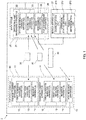
- FIG. 1 is a block diagram illustrating a schematic configuration of a cash handling system according to an embodiment of the present disclosure.
- a cash handling system 1 illustrated in FIG. 1 is an example of a money handling system.
- the cash handling system 1 is a system for distribution.
- the cash handling system 1 comprises a cash settlement apparatus 11, a POS register apparatus 15, a depositing and dispensing apparatus 21, a cash management apparatus 25, a POS management apparatus 26, and a server apparatus 27.
- the server apparatus 27 is communicably connected to the cash management apparatuses 25 and the POS management apparatuses 26 of a plurality of stores via the Internet.
- the server apparatus 27 manages the flow of commercial products and cash in each store.
- the number of the cash settlement apparatuses 11 installed in each store is not limited to the respective numbers indicated in FIG. 1 .
- the cash settlement apparatuses 11 are installed in a checkout counter 10 that is an example of a front office of a store.
- the cash settlement apparatus 11 is operated by a clerk, and is used in settlement processing between a clerk and a customer.
- the cash settlement apparatus 11 deposits payment paid by a customer or dispenses change that is given to a customer.
- One cash settlement apparatus 11 of the two cash settlement apparatuses 11 is an example of a first commercial product registration apparatus, and the other cash settlement apparatus 11 is an example of a second commercial product registration apparatus.
- the cash settlement apparatus 11 comprises: a first banknote handling apparatus 12 that handles a banknote, a first coin handling apparatus 13 that handles a coin C (see FIG. 6B ), and a register apparatus 14.
- the first coin handling apparatus 13 of the cash settlement apparatus 11 as an example of the first commercial product registration apparatus is an example of a proceeds-from-sales-collecting apparatus.
- the first coin handling apparatus 13 of the cash settlement apparatus 11 as an example of the second commercial product registration apparatus is an example of a change apparatus.
- the first coin handling apparatus 13 comprises a plurality of storage units that respectively stores the coins C of a plurality of denominations different from each other.
- the first coin handling apparatus 13 is configured such that a coin transport cassette 30 is attachable to the first coin handling apparatus 13.
- the first coin handling apparatus 13 stores a change fund in the coin transport cassette 30, in the storage units for each denomination.
- the first coin handling apparatus 13 stores the coin C inserted by a customer in the storage units for each denomination. In a case where there is change at the time of settlement of a commercial product, the first coin handling apparatus 13 dispenses the coin C in the storage units as the change to a customer.
- the first coin handling apparatus 13 stores the coin C in the storage units as proceeds from sales in the coin transport cassette 30.
- the register apparatus 14 may be a POS register that is operated by a clerk or may be a self-checkout register that is operated by a customer.
- At least one of the two cash settlement apparatuses 11 may be an apparatus that performs only depositing and dispensing processing of a coin.
- the first banknote handling apparatus 12 and the first coin handling apparatus 13 may be formed separately from the register apparatus 14, and these may be communicably connected to each other.
- the POS register apparatus 15 is installed in the checkout counter 10. A clerk manually deposits or dispenses cash to or from a drawer 40, thereby settlement processing of the POS register apparatus 15 is performed.
- the depositing and dispensing apparatus 21, the cash management apparatus 25, and the POS management apparatus 26 are installed in a back office 20 of the store.
- the depositing and dispensing apparatus 21 is communicably connected to each of the cash settlement apparatuses 11 and to the POS register apparatus 15.
- the depositing and dispensing apparatus 21 dispenses a change fund for being loaded to the cash settlement apparatus 11 and the POS register apparatus 15, or deposits proceeds from sales collected from the cash settlement apparatus 11 and the POS register apparatus 15.
- the depositing and dispensing apparatus 21 comprises a second banknote handling apparatus 22 that handles a banknote, and a second coin handling apparatus 23 that handles a coin.
- the second coin handling apparatus 23 is an example of a money handling apparatus. Details of the second coin handling apparatus 23 will be described later.
- the cash management apparatus 25 is communicably connected to each of the cash settlement apparatuses 11, to the POS register apparatus 15, to the depositing and dispensing apparatus 21, and to the server apparatus 27 via a local area network (LAN) or the like.
- the cash management apparatus 25 manages cash stored in each of the cash settlement apparatuses 11, in the POS register apparatus 15, and in the depositing and dispensing apparatus 21.
- the cash management apparatus 25 manages cash subjected to settlement processing in each of the cash settlement apparatuses 11 and in the POS register apparatus 15, and manages cash given or received between the cash settlement apparatus 11 and the depositing and dispensing apparatus 21, and cash given or received between the POS register apparatus 15 and the depositing and dispensing apparatus 21.
- the cash management apparatus 25 monitors an operation status of the depositing and dispensing apparatus 21.
- the cash management apparatus 25 transmits information on cash managed by the cash management apparatus 25, an operation status of the depositing and dispensing apparatus 21 and/or the like to the server apparatus 27.
- the cash management apparatus 25 acquires timing information to be described later from the server apparatus 27 and controls the second coin handling apparatus 23 such that dispensing processing of a change fund is performed at a timing based on the timing information.
- the cash management apparatus 25 may monitor whether the coin transport cassette 30 is attached to the cash settlement apparatus 11 or the depositing and dispensing apparatus 21 to transmit information on a monitoring result to the server apparatus 27.
- the cash management apparatus 25 may monitor whether the drawer 40 is attached to the POS register apparatus 15 or the depositing and dispensing apparatus 21 to transmit information on a monitoring result to the server apparatus 27.
- the POS management apparatus 26 manages the flow of commercial products.
- the POS management apparatus 26 is communicably connected to the server apparatus 27 via a LAN or the like.
- the POS management apparatus 26 transmits information on the flow of commercial products and/or the like to the server apparatus 27.
- the cash management apparatus 25 and the POS management apparatus 26 may be integrally formed.
- the server apparatus 27 is an example of a monitoring apparatus.
- the server apparatus 27 accumulates and manages information on a cash management state in the cash management apparatus 25, an operation status of the depositing and dispensing apparatus 21, the flow of commercial products managed by the POS management apparatus 26 and/or the like in each store.
- the server apparatus 27 has a function of determining a timing of performing dispensing processing of a change fund in the second coin handling apparatus 23 of the depositing and dispensing apparatus 21.
- the server apparatus 27 comprises a communication unit 271, an operation status grasping unit 272, and a timing determination unit 273.
- the operation status grasping unit 272 grasps an operation status of the second coin handling apparatus 23, that is, an execution status of depositing processing of proceeds from sales and dispensing processing of a change fund based on information acquired from the cash management apparatus 25 via the communication unit 271.
- the timing determination unit 273 determines a timing at which dispensing processing of a change fund is performed before depositing processing of proceeds from sales in the second coin handling apparatus 23, based on an operation status of the second coin handling apparatus 23 grasped by the operation status grasping unit 272.
- the timing determination unit 273 grasps a time slot during which depositing processing and dispensing processing are not performed in the second coin handling apparatus 23, and determines a timing of dispensing processing such that dispensing processing is completed before depositing processing of proceeds from sales, in the grasped time slot.
- the timing determination unit 273 may estimate a time slot during which depositing processing and dispensing processing are not performed, by statistically processing past operation statuses.
- the timing determination unit 273 may vary timings of dispensing processing for each day of the week or for each second coin handling apparatus 23. Timing information on a timing determined by the timing determination unit 273 is transmitted to the cash management apparatus 25, which is predetermined, via the communication unit 271.
- the coin transport cassette 30 is an example of a first cassette or a second cassette.
- the coin transport cassette 30 is an example of a money transport cassette.
- the coin transport cassette 30 is configured to be attachable to and detachable from the first coin handling apparatus 13 of the cash settlement apparatus 11, and to be attachable to and detachable from the second coin handling apparatus 23 of the depositing and dispensing apparatus 21.
- the coin transport cassette 30 is configured to be capable of giving or receiving the coin C between the coin transport cassette 30 and the first coin handling apparatus 13.
- the coin transport cassette 30 is configured to be capable of giving or receiving the coin C between the coin transport cassette 30 and the second coin handling apparatus 23.
- the first coin handling apparatus 13 and the second coin handling apparatus 23 are examples of a specific apparatus.
- the coin transport cassette 30 is configured such that the coin C therein cannot be taken out when the coin transport cassette 30 is detached from the first coin handling apparatus 13 and the second coin handling apparatus 23.
- a clerk uses the coin transport cassette 30 to transport the coin C between the first coin handling apparatus 13 and the second coin handling apparatus 23.
- a clerk uses the coin transport cassette 30 to transport the coin C between the first coin handling apparatus 13 and the second coin handling apparatus 23.
- the clerk cannot touch the coin C in the coin transport cassette 30 when transporting the coin C.
- the coin C can be transported in a safe state in terms of security.
- it may also be configured such that only authorized persons such as a manager of a store are allowed to open the coin transport cassette 30.
- the drawer 40 is configured to be attachable to and detachable from the POS register apparatus 15, and to be attachable to and detachable from the second coin handling apparatus 23 of the depositing and dispensing apparatus 21. For example, when a change fund is loaded or when proceeds from sales are collected, a clerk uses the drawer 40 to transport the coin C between the POS register apparatus 15 and the second coin handling apparatus 23.
- FIG. 2A is a top view illustrating a schematic configuration of the coin transport cassette.
- FIG. 2B is a cross-sectional view taken along IIB-IIB of FIG. 2A . Note that, the arrangement of each configuration of the coin transport cassette 30 or the like may be described using the directions indicated in FIG. 2A and FIG. 2B .
- the coin transport cassette 30 comprises a housing 31, a reception unit 32, a storage unit 33, a discharge unit 34, a feeding unit 35, and a connector 36.
- the reception unit 32 receives the coin C from the first coin handling apparatus 13 or the second coin handling apparatus 23.
- the reception unit 32 comprises a first reception port 321, a second reception port 322, and a reception port opening and closing unit 323.
- the first reception port 321 and the second reception port 322 are provided in a upper surface portion 311 of the housing 31.
- the first reception port 321 is configured to be capable of receiving the coin C from the first coin handling apparatus 13.
- the second reception port 322 is configured to be capable of receiving the coin C from the second coin handling apparatus 23.
- the reception port opening and closing unit 323 opens and closes the first reception port 321 and the second reception port 322.
- the reception port opening and closing unit 323 comprises a reception port blocking member 323A, and a reception port opening and closing driving unit.
- the reception port blocking member 323A blocks the first reception port 321 and the second reception port 322.
- the reception port opening and closing driving unit comprises an opening and closing motor, and an opening and closing mechanism.
- the opening and closing motor is driven by control of the first coin handling apparatus 13 or the second coin handling apparatus 23.
- the opening and closing mechanism moves the reception port blocking member 323A frontward and rearward.
- the opening and closing mechanism is controlled by the driving of the opening and closing motor to move the reception port blocking member 323A frontward and rearward, whereby both the first reception port 321 and the second reception port 322 can be opened or closed simultaneously. Note that, the first reception port 321 and the second reception port 322 may be opened or closed individually.
- the storage unit 33 is an inner space of the housing 31.
- the storage unit 33 stores the coin C received at the reception unit 32.
- the discharge unit 34 discharges the coin C stored in the storage unit 33.
- the discharge unit 34 comprises a discharge port 341, and a discharge port opening and closing unit 342.
- the discharge port 341 is an example of an opening, and is provided in a front surface portion 313 of the housing 31.
- the discharge port opening and closing unit 342 opens and closes the discharge port 341.
- the discharge port opening and closing unit 342 comprises a discharge port blocking member 342A, an opening and closing motor, and an opening and closing mechanism.
- the opening and closing motor is driven by control of the first coin handling apparatus 13 or the second coin handling apparatus 23.
- the opening and closing mechanism moves the discharge port blocking member 342A upward and downward.
- the opening and closing mechanism is controlled by the driving of the opening and closing motor to move the discharge port blocking member 342A upward and downward, whereby the discharge port 341 can be opened and closed.
- the feeding unit 35 feeds out the coin C stored in the storage unit 33 such that the coin C is discharged from the discharge unit 34.
- the feeding unit 35 comprises a transport mechanism 351, side wall portions 352, and a rear wall portion 353.
- the transport mechanism 351 comprises a transport motor, a driving pulley 351A, a driven pulley 351B, and a transport belt 351C.
- the transport motor is driven by control of the first coin handling apparatus 13 or the second coin handling apparatus 23.
- the driving pulley 351A is provided on a rotating shaft of the transport motor so as to extend rightward and leftward.
- the driven pulley 351B is supported by a bearing so as to extend rightward and leftward.
- the transport belt 351C is wound around the driving pulley 351A and the driven pulley 351B.
- the coin C received through the reception unit 32 is placed on the transport belt 351C.
- the side wall portions 352 are provided on both sides of the transport belt 351C in the width direction, respectively.
- the rear wall portion 353 is provided rearward from the transport belt 351C.
- the connector 36 is provided so as to be exposed to the outside from a left surface portion 316 of the housing 31.
- the connector 36 is connected to a connector of the first coin handling apparatus 13 when the coin transport cassette 30 is attached to the first coin handling apparatus 13.
- the connector 36 is connected to a connector (not illustrated) of the second coin handling apparatus 23 when the coin transport cassette 30 is attached to the second coin handling apparatus 23.
- the connector 36 When the connector 36 is connected to the connector of the first coin handling apparatus 13 or the second coin handling apparatus 23, power is supplied to the opening and closing motor of the reception port opening and closing unit 323, the opening and closing motor of the discharge unit 34, the transport motor, and/or the like via the connector 36 such that the opening and closing motor of the reception port opening and closing unit 323, the opening and closing motor of the discharge unit 34, the transport motor, and/or the like operate.
- the coin transport cassette 30 can be controlled by the first coin handling apparatus 13 or the second coin handling apparatus 23 via the connector 36.
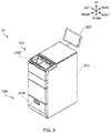
- FIG. 3 is a perspective view of an external appearance of the second coin handling apparatus.
- FIG. 4A is a perspective view illustrating a state in which a cover of the second coin handling apparatus is opened.
- FIG. 4B is a perspective view illustrating a state in which the coin transport cassette is attached to the second coin handling apparatus.
- FIG. 5A is a schematic diagram illustrating an internal configuration of the second coin handling apparatus when viewed from a right side, illustrating a state when proceeds from sales collected by the coin transport cassette are deposited.
- FIG. 5B is a schematic diagram illustrating the internal configuration of the second coin handling apparatus in the state when the proceeds from sales collected by the coin transport cassette are deposited, when the second coin handling apparatus is viewed from a front side.
- FIG. 6A is a schematic diagram illustrating the internal configuration of the second coin handling apparatus when viewed from the right side, illustrating a state when a change fund is dispensed into a drawer.
- FIG. 6B is a schematic diagram illustrating the internal configuration of the second coin handling apparatus in the state when the change fund is dispensed into the drawer, when the second coin handling apparatus is viewed from the front side.
- FIG. 6A is a schematic diagram illustrating the internal configuration of the second coin handling apparatus when viewed from the right side, illustrating a state when a change fund is dispensed into a drawer.
- FIG. 6B is a schematic diagram illustrating the internal configuration of the second coin handling apparatus in the state when the change fund is dispensed into the drawer, when the second coin handling apparatus is viewed from the
- FIG. 7A is a schematic diagram illustrating the internal configuration of the second coin handling apparatus when viewed from the right side, illustrating a state when the change fund is dispensed into the coin transport cassette.
- FIG. 7B is a schematic diagram illustrating the internal configuration of the second coin handling apparatus in the state when the change fund is dispensed into the coin transport cassette, when the second coin handling apparatus is viewed from the front side.
- the second coin handling apparatus 23 comprises a housing 231, a first cassette attachment unit 232, a depositing unit 233, a dispensing unit 234, and an operation display 250.
- the first cassette attachment unit 232 is formed of a downwardly recessed portion provided in a frontward portion of an upper surface portion of the housing 231. As illustrated in FIG. 4B , the first cassette attachment unit 232 is configured to allow the coin transport cassette 30 to be attached to the first cassette attachment unit 232 with the discharge port 341 facing rearward. The first cassette attachment unit 232 is configured such that, when the coin transport cassette 30 is attached to the first cassette attachment unit 232, the connector 36 of the coin transport cassette 30 is connected to a connector of the first cassette attachment unit 232.
- the depositing unit 233 is provided in an upper and front portion of the housing 231. That is, the depositing unit 233 is provided on a side on which a clerk stands when operating the second coin handling apparatus 23.
- the depositing unit 233 is configured such that the coin C can be deposited into the second coin handling apparatus 23.
- the depositing unit 233 comprises a first reception port 233A, a second reception port 233B, and a cover 233C.
- the first reception port 233A is an opening that opens frontward.
- the first reception port 233A is provided at a position facing the discharge port 341 of the coin transport cassette 30 attached to the first cassette attachment unit 232.
- the first reception port 233A is configured to be capable of receiving the coin C discharged rearward from the coin transport cassette 30.
- the second reception port 233B is an opening that opens downward. As illustrated in FIG. 4B , the second reception port 233B is configured to be covered by the coin transport cassette 30 when the coin transport cassette 30 is attached to the first cassette attachment unit 232. That is, when the coin transport cassette 30 is attached to the first cassette attachment unit 232, it is configured such that the coin C cannot be deposited through the second reception port 233B into the second coin handling apparatus 23.
- the cover 233C is configured to turn around a turning shaft provided in the upper surface portion of the housing 231 and extending rightward and leftward, and is configured to be switchable between a closed state in which the cover 233C covers the first reception port 233 A and the first cassette attachment unit 232 as illustrated in FIG. 3 and an open state in which the cover 233C does not cover the first reception port 233A and the first cassette attachment unit 232 as illustrated in FIG. 4A and FIG. 4B .
- the cover 233C is provided with an exposure port 233C1 that exposes the second reception port 233B when the cover 233C is in the closed state.
- the dispensing unit 234 comprises a drawer portion 234A that can be drawn from a lower portion of the housing 231 onto a side of a clerk.
- a second cassette attachment unit 234B (see FIG. 6A ) is provided in a front-side portion in the drawer portion 234A.
- the coin transport cassette 30 is attached to the second cassette attachment unit 234B.
- the second cassette attachment unit 234B is configured such that, when the coin transport cassette 30 is attached to the second cassette attachment unit 234B, the connector 36 of the coin transport cassette 30 is connected to a connector of the second cassette attachment unit 234B.
- a drawer attachment unit 234C (see FIG. 6A ) is provided rearward from the second cassette attachment unit 234B in the drawer portion 234A.
- the drawer 40 is attached to the drawer attachment unit 234C. That is, the second cassette attachment unit 234B is provided at a position different from a position of the drawer attachment unit 234C.
- Such a configuration makes it possible to attach the coin transport cassette 30 to the second cassette attachment unit 234B when the drawer 40 is attached to the drawer attachment unit 234C.
- the operation display 250 is formed of a touch screen-type liquid crystal display apparatus.
- the operation display 250 functions as an operation unit for inputting information on cash handling and identification of an operator in the second banknote handling apparatus 22 and the second coin handling apparatus 23, and as a display that displays information on cash handling and identification.
- the operation display 250 may be formed separately from the depositing and dispensing apparatus 21 or may be integrally formed with the depositing and dispensing apparatus 21.
- the operation display 250 may also be configured such that the operation unit and the display are provided independently of each other.
- the second coin handling apparatus 23 further comprises a feeding unit 235, an upper-side transport unit 236, a recognition unit 237, a storage unit 238, a reject unit 239, an overflow storage unit 240, a forged coin storage unit 241, a return unit 242, a plurality of upper chutes 243, a lower-side transport unit 244, a switching unit 247, an identification unit 248, and a control unit 249. Structure of the identification unit 248 and the control unit 249 will be discussed later with respect to processing circuitry 400 in FIG. 9 .
- the feeding unit 235 is configured to be capable of receiving the coin C deposited from the coin transport cassette 30 via the first reception port 233A and the coin C deposited through the second reception port 233B, feeding out the coin C one by one, and causing the coin C to fall into the return unit 242.
- a mechanism to feed out the coin C in the feeding unit 235 it is possible to exemplify a mechanism in which a rotary disk rotating in an inclined state is used and the coin C is picked up one by one by a plurality of projection members on an outer region of a surface of the rotary disk and is fed out.
- the upper-side transport unit 236 transports the coin C fed out of the feeding unit 235.
- the upper-side transport unit 236 is an example of a first transport unit that deposits the coin C in the coin transport cassette 30 into the housing 231, where the coin transport cassette 30 is attached to the first cassette attachment unit 232.
- the recognition unit 237 is provided in the upper-side transport unit 236, recognizes denomination, authenticity, fitness, and/or the like of coins deposited through the depositing unit 233, and counts the coins.
- the storage unit 238 comprises storage boxes 238A, 238B, 238C, 238D, 238E, 238F, 238G, and 238H (which may be referred to hereinafter as "storage boxes 238A to 238H").
- the storage boxes 238A to 238H are configured to be capable of storing the coin C and feeding out the coin C that has been stored.
- the storage boxes 238A to 238D are provided so as to be side by side in the front-rear direction on the right side in the housing 231.
- the storage boxes 238E to 238H are provided so as to be side by side in the front-rear direction on the left side in the housing 231.
- the storage boxes 238E to 238H are hidden behind the storage boxes 238A to 238D.
- the storage boxes 238B to 238D and 238F to 238H are hidden behind the storage boxes 238A and 238E.
- Denominations that are stored in the storage boxes 238A to 238H, respectively, are set in advance. As a mechanism to feed out the coin C in the storage boxes 238A to 238H, it is possible to exemplify a mechanism similar to that of the feeding unit 235.
- the reject unit 239 stores, as a rejected coin, the coin C recognized not as a coin to be handled or as unrecognizable by the recognition unit 237.
- the reject unit 239 is configured to be drawable from a side of a front surface of the housing 231 by opening a cover of the housing 231.
- the overflow storage unit 240 stores, as an overflow coin, the coin C that cannot be held in a case where the holding number of the coins C in the storage boxes 238A to 238H exceeds a predetermined holding number that has been set.
- the overflow storage unit 240 is configured to be drawable from the side of the front surface of the housing 231.
- the forged coin storage unit 241 stores the coin C recognized as a forged coin by the recognition unit 237.
- the forged coin storage unit 241 is configured to be drawable from the side of the front surface of the housing 231.
- the return unit 242 stores the coin C that has fallen from the feeding unit 235.
- the return unit 242 is configured to be drawable from the side of the front surface of the housing 231.
- the upper chutes 243 are provided downstream of the recognition unit 237 in the upper-side transport unit 236 in the transport direction of the coin C.
- the upper chutes 243 are provided side by side in a row in the transport direction of the coin C.
- eight upper chutes 243A are configured to be capable of guiding the coin C to any one of the storage boxes 238A to 238H.
- Another upper chute 243B is configured to be capable of guiding a rejected coin to the reject unit 239.
- Yet another upper chute 243C is configured to be capable of guiding an overflow coin to the overflow storage unit 240.
- One upper chute 243D that is the remaining upper chute 243 is configured to be capable of guiding a forged coin to the forged coin storage unit 241.
- the upper chutes 243 are normally closed by gates, and guide the coin C to each portion described above by opening the gates.
- the lower-side transport unit 244 transports the coin C fed out of the storage unit 238 to the drawer 40 attached to the drawer attachment unit 234C or the coin transport cassette 30 attached to the second cassette attachment unit 234B.
- the lower-side transport unit 244 is an example of a second transport unit that dispenses the coin C in the housing 231 as a change fund into the coin transport cassette 30 attached to the second cassette attachment unit 234B.
- the lower-side transport unit 244 comprises a first route forming portion 245 and a second route forming portion 246.
- the first route forming portion 245 forms a first route 245R that guides the coin C fed out of the storage unit 238 to the drawer 40 attached to the drawer attachment unit 234C.
- the first route forming portion 245 comprises drawer chutes 245A, 245B, 245C, 245D, 245E, 245F, 245G, and 245H (which may be referred to hereinafter as "drawer chutes 245A to 245H").
- the drawer chutes 245A to 245H are provided one by one downward from the storage boxes 238A to 238H, respectively.
- the drawer chutes 245E to 245H are hidden behind the drawer chutes 245A to 245D.
- FIG. 1 the drawer chutes 245E to 245H are hidden behind the drawer chutes 245A to 245D.
- the drawer chutes 245B to 245D and 245F to 245H are hidden behind the drawer chutes 245A and 245E.
- the drawer chutes 245A to 245H are configured to be capable of guiding the coin C stored in the storage boxes 238A to 238H to the drawer 40 attached to the drawer attachment unit 234C.
- the second route forming portion 246 forms a second route 246R that guides the coin C fed out of the storage unit 238 to the coin transport cassette 30 attached to the second cassette attachment unit 234B.
- the second route forming portion 246 is provided between a row formed of the drawer chutes 245A to 245D in the front-rear direction and a row formed of the drawer chutes 245E to 245H in the front-rear direction.
- the second route forming portion 246 comprises a transport motor, a driving pulley 246A, a driven pulley 246B, and a transport belt 246C.
- the transport motor is driven by control of the control unit 249.
- the driving pulley 246A is provided on a rotating shaft of the transport motor so as to extend rightward and leftward in a front and lower portion of the housing 231.
- the driven pulley 246B is received by a bearing so as to extend rightward and leftward in a rear and lower portion of the housing 231.
- the transport belt 246C is wound around the driving pulley 246A and the driven pulley 246B.
- the transport belt 246C is configured to be capable of guiding the coin C stored in the storage boxes 238A to 238H to the second reception port 322 of the coin transport cassette 30 attached to the second cassette attachment unit 234B.
- the switching unit 247 is driven by control of the control unit 249.
- the switching unit 247 switches a guide destination of the coin C stored in the storage boxes 238A to 238H to the first route 245R (the drawer chutes 245A to 245H) as illustrated in FIG. 6A and FIG. 6B or the second route 246R (the transport belt 246C) as illustrated in FIG. 7A and FIG. 7B .
- the identification unit 248 identifies an operator of the second coin handling apparatus 23. The identification method by the identification unit 248 will be described later.
- the control unit 249 controls the entire operation of the second coin handling apparatus 23.
- the control unit 249 performs control such that the coin C collected from the first coin handling apparatus 13 by the coin transport cassette 30 and the coin C collected from the POS register apparatus 15 by the drawer 40 are deposited as proceeds from sales.
- the control unit 249 performs control such that the coin C stored in the storage boxes 238A to 238H is dispensed as a change fund into the coin transport cassette 30 or the drawer 40. Such depositing processing of proceeds from sales and dispensing processing of a change fund will be described later. Additional structure of control unit 249 will be discussed later with respect to processing circuitry 400 illustrated in FIG. 9 .
- a clerk opens the cover 233C to expose the first cassette attachment unit 232.
- the clerk attaches the coin transport cassette 30, in which the first reception port 321, the second reception port 322 and the discharge port 341 are closed, to the first cassette attachment unit 232 as illustrated in FIG. 4B , FIG. 5A and FIG. 5B .
- the second coin handling apparatus 23 begins to supply power to the coin transport cassette 30 via the connector of the first cassette attachment unit 232.
- the control unit 249 of the second coin handling apparatus 23 controls the coin transport cassette 30 such that the coin C stored in the coin transport cassette 30 is discharged.
- the control unit 249 controls the opening and closing motor of the discharge port opening and closing unit 342 of the coin transport cassette 30 such that the discharge port 341 opens.
- the control unit 249 controls the transport motor of the feeding unit 35 of the coin transport cassette 30 such that the transport belt 351C rotates, thereby sequentially discharging the coin C stored in the storage unit 33 so as to be fed out of the discharge port 341.
- the control unit 249 controls the transport motor of the feeding unit 35 to cause the rotation of the transport belt 351C to end, and controls the opening and closing motor of the discharge port opening and closing unit 342 such that the discharge port 341 is closed.
- the coin C fed out of the coin transport cassette 30 passes through the first reception port 233A, and falls into the feeding unit 235 via a feeding mechanism provided in the first reception port 233A on an inner side of the housing 231.
- the control unit 249 controls the feeding unit 235 and the upper-side transport unit 236 such that the coin C fed out of the coin transport cassette 30 is transported.
- the coin that is transported is subjected to recognition of denomination, authenticity, fitness, and/or the like by the recognition unit 237.
- the control unit 249 controls the upper-side transport unit 236 and the gates based on a recognition result by the recognition unit 237 such that the coin C that can be deposited is stored in the storage boxes 238A to 238H for each denomination, and that a rejected coin, an overflow coin, and a forged coin are stored in the reject unit 239, the overflow storage unit 240, and the forged coin storage unit 241, respectively.
- the control unit 249 transmits information on the denominations and number of the coins C, which have been deposited, to the cash management apparatus 25. Thereafter, a clerk detaches the coin transport cassette 30 from the second coin handling apparatus 23, and closes the cover 233C as illustrated in FIG. 3 .
- the cover 233C is closed so that the coin transport cassette 30 cannot be attached to the first cassette attachment unit 232.
- a clerk inserts the coin C collected by the drawer 40 into the exposure port 233C1.
- the coin C passes through the second reception port 233B, falls into the feeding unit 235 via a feeding mechanism provided in the second reception port 233B on an inner side of the housing 231, and is stored in the storage boxes 238A to 238H, the reject unit 239, the overflow storage unit 240, or the forged coin storage unit 241 based on a recognition result by the recognition unit 237.
- a clerk draws the drawer portion 234A of the second coin handling apparatus 23 onto a side of the clerk, and attaches the drawer 40, which is empty, to the drawer attachment unit 234C. Subsequently, the clerk attaches the coin transport cassette 30, which is empty and in which the first reception port 321, the second reception port 322, and the discharge port 341 are closed, to the second cassette attachment unit 234B. As illustrated in FIG. 6A, FIG. 6B , FIG. 7A, and FIG. 7B , the clerk pushes and inserts the drawer portion 234A into the housing 231 to realize a state in which the coin C can be stored in the coin transport cassette 30 and the drawer 40.
- the second coin handling apparatus 23 When the drawer portion 234A is inserted into the housing 231, the second coin handling apparatus 23 begins to supply power to the coin transport cassette 30 via the connector of the second cassette attachment unit 234B.
- the control unit 249 of the second coin handling apparatus 23 controls the coin transport cassette 30 such that the second reception port 322 of the coin transport cassette 30 opens.
- the control unit 249 causes the first reception port 321 and the second reception port 322 to open simultaneously by controlling the opening and closing motor of the reception port opening and closing unit 323 of the coin transport cassette 30 to move the reception port blocking member 323A.
- control unit 249 When the first reception port 321 and the second reception port 322 of the coin transport cassette 30 are opened, the control unit 249 performs control such that the coin transport cassette 30 and the drawer 40 are replenished with the coins C of predetermined denominations by a predetermined number.
- control unit 249 controls the storage boxes 238Ato 238H and the switching unit 247 such that the coin C fed out of the storage boxes 238A to 238H is guided to the first route 245R (the drawer chutes 245A to 245H) as indicated by arrows C1 in FIG. 6B .
- the drawer 40 is replenished with the coin C guided to the first route 245R.
- the control unit 249 controls the storage boxes 238A to 238H and the switching unit 247 such that the coin C fed out of the storage boxes 238A to 238H is guided to the second route 246R (the transport belt 246C) as indicated by arrows C2 in FIG. 7B .
- the control unit 249 further controls the transport motor of the second route forming portion 246 such that the coin transport cassette 30 is replenished with the coin C guided onto the transport belt 246C via the second reception port 322. In this manner, the coin transport cassette 30 and the drawer 40 can be replenished with the coin C in the storage boxes 238A to 238H without detaching the coin transport cassette 30 and the drawer 40 from the second coin handling apparatus 23.
- control unit 249 may control the switching unit 247 such that the coin transport cassette 30 is replenished with the coin C in all the remaining storage boxes.
- control unit 249 controls the coin transport cassette 30 such that the second reception port 322 of the coin transport cassette 30 is closed.
- the control unit 249 controls the opening and closing motor of the reception port opening and closing unit 323 of the coin transport cassette 30 to cause the reception port blocking member 323A to move, thereby closing the first reception port 321 and the second reception port 322 simultaneously.
- FIG. 8 is a timing chart illustrating an exemplary specific operation example of the cash handling system.
- the server apparatus 27 grasps an operation status of the second coin handling apparatus 23 of a predetermined store based on information from the cash management apparatus 25 of the store.
- the server apparatus 27 determines a timing of dispensing processing such that dispensing processing of a change fund is completed before depositing processing of proceeds from sales in a time slot during which the second coin handling apparatus 23 is estimated not to be in operation.
- the server apparatus 27 transmits timing information on the determined timing to the cash management apparatus 25 of the predetermined store.
- the timing of performing dispensing processing determined by the server apparatus 27 may be one timing or a plurality of timings per day.
- the timing of performing dispensing processing determined by the server apparatus 27 may be on business days or holidays of the store.
- the server apparatus 27 may transmit timing information based on a grasped operation status daily, for each day of the week of the store, for each predetermined date, for each predetermined season, or for each predetermined period.
- the cash management apparatus 25 transmits an instruction signal to the control unit 249 of the second coin handling apparatus 23 such that dispensing processing of a change fund is performed at a timing based on timing information from the server apparatus 27.
- the cash management apparatus 25 preferably transmits an instruction signal based on the timing information.
- the cash management apparatus 25 may transmit an instruction signal based on the last acquired timing information to the control unit 249 daily, on business days of the store or on holidays of the store.
- the control unit 249 of the second coin handling apparatus 23 performs control such that dispensing processing of a change fund into the coin transport cassette 30 attached to the second cassette attachment unit 234B (hereinafter, this coin transport cassette 30 may be referred to as "first dispensing processing target cassette 30") is performed at a timing based on an instruction signal from the cash management apparatus 25.
- the control unit 249 causes dispensing processing of a change fund into the first dispensing processing target cassette 30 is performed between a time T0 and a time T1 between which depositing processing of proceeds from sales from the coin transport cassette 30 (hereinafter, may be referred to as "first depositing processing target cassette 30") is not performed as indicated by a solid line in FIG. 8 .
- the first dispensing processing target cassette 30 may be attached to the second cassette attachment unit 234B by a clerk who takes out the coin transport cassette 30 in which is the last prepared change fund is stored, by a clerk who notices that the first dispensing processing target cassette 30 is not attached to the second cassette attachment unit 234B, or by an attachment apparatus such as a robot.
- the control unit 249 may perform notification control to prompt attachment of the first dispensing processing target cassette 30.
- the notification prompting the attachment of the first dispensing processing target cassette 30 may be performed by a display on the operation display 250, by an emission apparatus such as a lamp, or by a sound producing apparatus such as a speaker.
- control unit 249 When the dispensing processing of a change fund into the first dispensing processing target cassette 30 is performed, the control unit 249 performs control such that a change fund in a money quantity for each denomination set in advance is dispensed.
- a money quantity may be a number of money (banknotes and coins) or an amount.
- control unit 249 may perform control such that a change fund in an amount based on the increase instruction is dispensed.
- the identification unit 248 first causes the operation display 250 to display a login screen for identifying an operator of the second coin handling apparatus 23.
- a login screen it is possible to exemplify a screen that prompts a username and a password to be inputted.
- the identification unit 248 identifies whether an operator of the second coin handling apparatus 23 is an authorized person allowed to increase a change fund (hereinafter, this authority may be referred to as "increase authority") based on information inputted into the login screen, and transmits an identification result to the control unit 249.
- an ID card or biometrics such as a fingerprint, a vein, and an iris may be utilized as identification by the identification unit 248.
- the control unit 249 performs control such that the operation display 250 displays an operation button for increase instructions.
- the control unit 249 receives an increase instruction based on an operation of the operation button, the control unit 249 performs control such that a change fund in an amount based on the increase instruction is dispensed.
- an increased quantity may be configured to be set arbitrarily by an operator, may be configured to be selected by an operator from a plurality of increased quantities set in advance, may be determined as a fixed quantity, or may be determined in accordance with the occupational post of an operator. It may also be configured such that a physical button for increase instructions is provided in the second coin handling apparatus 23, and that the control unit 249 performs control such that an increase instruction is received based on an operation of the physical button.
- control unit 249 may perform control such that a change fund in a money quantity for each denomination set in advance is dispensed without causing the operation display 250 to display the operation button for increase instructions, or may cause the operation display 250 to perform a display to prompt the username and the password to be inputted again.
- the control unit 249 may perform control such that dispensing processing of a change fund into the second dispensing processing target cassette 30 is performed between the time T1 and a time T2 between which depositing processing of proceeds from sales from the first depositing processing target cassette 30 is not performed as indicated by a two-dot chain line in FIG. 8 .
- the replacement of the coin transport cassette 30 at this time may be performed by a clerk or an attachment apparatus.
- the amount of the change fund at this time is basically a money quantity for each denomination set in advance, but may be an increased amount based on an identification result by the identification unit 248.
- control unit 249 may perform control such that dispensing processing with respect to further at least one coin transport cassette 30 (dispensing processing target cassette 30) is performed.
- at least one dispensing processing target cassette 30 in which a change fund is stored is prepared.
- the control unit 249 performs control such that proceeds from sales in the first depositing processing target cassette 30 are deposited from a time T3 as illustrated by a solid line in FIG. 8 . Since at least one dispensing processing target cassette 30 in which a change fund is stored is prepared as described above before the depositing of the proceeds from sales starts, the depositor can bring the dispensing processing target cassette 30, in which a change fund is stored, to the cash settlement apparatus 11 without waiting after attaching the first depositing processing target cassette 30 to the first cassette attachment unit 232.
- the control unit 249 may also perform control such that dispensing processing of a change fund into the coin transport cassette 30 attached to the second cassette attachment unit 234B (hereinafter, this coin transport cassette 30 may be referred to as "third dispensing processing target cassette 30") is performed while depositing processing of proceeds from sales of the first depositing processing target cassette 30 is performed as illustrated by a two-dot chain line in FIG. 8 . That is, the control unit 249 may perform control such that dispensing processing of a change fund into the third dispensing processing target cassette 30 starts at a time T4 earlier than a time T5 at which the depositing processing from the first depositing processing target cassette 30 ends.
- the replacement of the dispensing processing target cassette 30 at this time may be performed before or after the depositing processing of proceeds from sales starts.
- the replacement of the dispensing processing target cassette 30 at this time may be performed by a depositor, by a clerk other than the depositor, or by an attachment apparatus.
- the amount of the change fund at this time is basically a money quantity for each denomination set in advance, but may be an increased amount based on an identification result by the identification unit 248.
- the dispensing processing may end earlier than the depositing processing depending on the amounts of the proceeds from sales and the change fund.
- control unit 249 performs control such that depositing processing or dispensing processing is performed in accordance with the attachment of the coin transport cassette 30 to the first cassette attachment unit 232 or the second cassette attachment unit 234B. Depositing processing and dispensing processing may be performed in parallel.
- FIG . 9 is a block diagram of processing circuitry that performs computer-based operations in accordance with the present disclosure.
- FIG. 9 illustrates processing circuitry 400 of identification unit 248 and control unit 249, which is a component of second coin handling apparatus 23.
- Processing circuitry 400 is used to control any computer-based and cloud-based control processes, descriptions or blocks in flowcharts can be understood as representing modules, segments or portions of code which include one or more executable instructions for implementing specific logical functions or steps in the process, and alternate implementations are included within the scope of the exemplary embodiments of the present advancements in which functions can be executed out of order from that shown or discussed, including substantially concurrently or in reverse order, depending upon the functionality involved, as would be understood by those skilled in the art.
- the functionality of the elements disclosed herein may be implemented using circuitry or processing circuitry which may include general purpose processors, special purpose processors, integrated circuits, ASICs ("Application Specific Integrated Circuits"), conventional circuitry and/or combinations thereof which are configured or programmed to perform the disclosed functionality.
- Processors are processing circuitry or circuitry as they include transistors and other circuitry therein.
- the processor may be a programmed processor which executes a program stored in a memory.
- the processing circuitry, units, or means are hardware that carry out or are programmed to perform the recited functionality.
- the hardware may be any hardware disclosed herein or otherwise known which is programmed or configured to carry out the recited functionality.
- the processing circuitry 400 includes a CPU 401 which performs one or more of the control processes discussed in this disclosure.
- the process data and instructions may be stored in memory 402.
- These processes and instructions may also be stored on a storage medium disk 404 such as a hard drive (HDD) or portable storage medium or may be stored remotely.
- the claimed advancements are not limited by the form of the computer-readable media on which the instructions of the inventive process are stored.
- the instructions may be stored on CDs, DVDs, in FLASH memory, RAM, ROM, PROM, EPROM, EEPROM, hard disk or any other non-transitory computer readable medium of an information processing device with which the processing circuitry 400 communicates, such as a server or computer.
- the processes may also be stored in network based storage, cloud-based storage or other mobile accessible storage and executable by processing circuitry 400.
- claimed advancements may be provided as a utility application, background daemon, or component of an operating system, or combination thereof, executing in conjunction with CPU 401 and an operating system such as Microsoft Windows, UNIX, Solaris, LINUX, Apple MAC-OS, Apple iOS and other systems known to those skilled in the art.
- an operating system such as Microsoft Windows, UNIX, Solaris, LINUX, Apple MAC-OS, Apple iOS and other systems known to those skilled in the art.
- a processing circuit includes a particularly programmed processor, for example, processor (CPU) 401, as shown in FIG. 9 .
- a processing circuit also includes devices such as an application specific integrated circuit (ASIC) and conventional circuit components arranged to perform the recited functions.
- ASIC application specific integrated circuit
- processing circuitry 400 may be a computer or a particular, special-purpose machine. Processing circuitry 400 is programmed to execute processing to second control coin handling apparatus 23.
- CPU 401 may be implemented on an FPGA, ASIC, PLD or using discrete logic circuits, as one of ordinary skill in the art would recognize. Further, CPU 401 may be implemented as multiple processors cooperatively working in parallel to perform the instructions of the inventive processes described above.
- the processing circuitry 400 in FIG. 9 also includes a network controller 406, such as an Ethernet PRO network interface card, for interfacing with network 500.
- the network 500 can be a public network, such as the Internet, or a private network such as a local area network (LAN) or wide area network (WAN), or any combination thereof and can also include Public Switched Telephone Network (PSTN) or Integrated Services Digital Network (ISDN) sub-networks.
- PSTN Public Switched Telephone Network
- ISDN Integrated Services Digital Network
- the network 500 can also be wired, such as an Ethernet network, universal serial bus (USB) cable, or can be wireless such as a cellular network including EDGE, 3G and 4G wireless cellular systems.
- the wireless network can also be Wi-Fi, wireless LAN, Bluetooth, or any other wireless form of communication that is known.
- network controller 406 may be compliant with other direct communication standards, such as Bluetooth, a near field communication (NFC), infrared ray or other.
- the processing circuitry 400 further includes a display controller 408, such as a graphics card or graphics adaptor for interfacing with display 409, such as a monitor.
- a display controller 408 such as a graphics card or graphics adaptor for interfacing with display 409, such as a monitor.
- An I/O interface 412 interfaces with a keyboard and/or mouse 414 as well as a touch screen panel 416 on or separate from display 109. I/O interface 412 also connects to a variety of peripherals 418.
- the storage controller 424 connects the storage medium disk 404 with communication bus 426, which may be an ISA, EISA, VESA, PCI, or similar, for interconnecting all of the components of the processing circuitry 400.
- communication bus 426 may be an ISA, EISA, VESA, PCI, or similar, for interconnecting all of the components of the processing circuitry 400.
- a description of the general features and functionality of the display 409, keyboard and/or mouse 414, as well as the display controller 408, storage controller 424, network controller 406, and I/O interface 412 is omitted herein for brevity as these features are known.
- circuitry configured to perform features described herein may be implemented in multiple circuit units (e.g., chips), or the features may be combined in circuitry on a single chipset.
- the functions and features described herein may also be executed by various distributed components of a system.
- one or more processors may execute these system functions, wherein the processors are distributed across multiple components communicating in a network.
- the distributed components may include one or more client and server machines, which may share processing, in addition to various human interface and communication devices (e.g., display monitors, smart phones, tablets, personal digital assistants (PDAs)).
- the network may be a private network, such as a LAN or WAN, or may be a public network, such as the Internet. Input to the system may be received via direct user input and received remotely either in real-time or as a batch process. Additionally, some implementations may be performed on modules or hardware not identical to those described. Accordingly, other implementations are within the scope that may be claimed.
- the control unit 249 of the second coin handling apparatus 23 operates such that dispensing processing of a change fund into the first dispensing processing target cassette 30 (second cassette) is performed before depositing processing of proceeds from sales of the first depositing processing target cassette 30 (first cassette) brought by a depositor. For this reason, the depositor can bring the first dispensing processing target cassette 30, in which a change fund is stored, to the cash settlement apparatus 11 without waiting after causing the second coin handling apparatus 23 to start depositing processing of the first depositing processing target cassette 30. Accordingly, it is possible to provide the second coin handling apparatus 23 capable of shortening a waiting time for a change fund to be dispensed.
- the control unit 249 performs control such that dispensing processing of a change fund into the third dispensing processing target cassette 30 (third cassette) is performed while depositing processing of proceeds from sales from the first depositing processing target cassette 30 is performed. For this reason, the next change fund can be prepared earlier.
- the control unit 249 causes the depositing processing of proceeds from sales from the first depositing processing target cassette 30 brought by a depositor to start after the dispensing processing of a change fund into the first dispensing processing target cassette 30 (second cassette) and dispensing processing of a change fund into the second dispensing processing target cassette 30 (third cassette) attached to the second cassette attachment unit 234B in place of the first dispensing processing target cassette 30 are performed.
- the second coin handling apparatus 23 is capable of shortening waiting times for more change funds to be dispensed.
- the control unit 249 performs control such that a change fund in a money quantity for each denomination set in advance is prepared. Accordingly, a clerk can bring a change fund in an appropriate amount to the cash settlement apparatus 11 without performing an operation of setting an amount of a change fund.
- control unit 249 When the control unit 249 receives an increase instruction, the control unit 249 performs control such that a change fund in an amount in accordance with the increase instruction is prepared. Accordingly, a clerk can bring a change fund in an amount larger than a money quantity for each denomination set in advance to the cash settlement apparatus 11 as needed.
- the control unit 249 performs control such that a change fund in an amount in accordance with the increase instruction issued by the operator is prepared.
- the second coin handling apparatus 23 performs depositing processing from or dispensing processing into the coin transport cassette 30 capable of giving or receiving the coin C only between the coin transport cassette 30 and the second coin handling apparatus 23 or only between the coin transport cassette 30 and the first coin handling apparatus 13. Accordingly, it is possible to prevent the coin C from being taken out from the coin transport cassette 30 while the coin transport cassette 30 is transported.
- the server apparatus 27 determines, based on information from the cash management apparatus 25 of a predetermined store, a timing of dispensing processing such that dispensing processing of a change fund is completed in a time slot during which the second coin handling apparatus 23 of the store is estimated not to be in operation.
- the server apparatus 27 transmits timing information on the determined timing to the second coin handling apparatus 23.
- the control unit 249 of the second coin handling apparatus 23 causes dispensing processing of a change fund to be performed at the timing based on the timing information from the server apparatus 27.
- the second coin handling apparatus 23 is capable of taking such a status into consideration and performing dispensing processing of a change fund before depositing processing of proceeds from sales based on an appropriate timing determined by the server apparatus 27.
- control unit 249 may perform control such that a change fund is dispensed into the drawer 40 (second cassette) attached to the drawer attachment unit 234C (second cassette attachment unit) before depositing processing of proceeds from sales of the coin transport cassette 30. It may also be configured such that a drawer attachment unit for depositing (first cassette attachment unit), to which the drawer 40 in which proceeds from sales are stored can be attached, is provided in the housing 231, and that, before depositing processing of proceeds from sales of the drawer 40, the control unit 249 performs control such that a change fund is dispensed into the coin transport cassette 30 attached to the second cassette attachment unit 234B or performs control such that a change fund is dispensed into the drawer 40 attached to the drawer attachment unit 234C (second cassette attachment unit).
- the second coin handling apparatus 23 may not identify an operator having issued an increase instruction, and may increase a change fund whoever the operator is.
- the second coin handling apparatus 23 may not have a function of increasing a change fund.
- the second coin handling apparatus 23 may be configured to receive a setting of an amount of a change fund for each dispensing processing.
- the cash management apparatus 25 grasps an operation status of the second coin handling apparatus 23, and that the cash management apparatus 25 determines a timing of dispensing processing of a change fund, which is performed before depositing processing of proceeds from sales.
- the cash handling system 1 may not have a function of determining a timing of dispensing processing of a change fund. In this case, it may also be configured such that dispensing processing is performed at a timing set in advance every time, or that a clerk can set the timing every time.
- the second coin handling apparatus 23 is provided with a temporary storage unit that temporarily holds the coin C deposited through the depositing unit 233 before the coin C is stored in the storage unit 238, and that the control unit 249 performs control such that the coin C held in the temporary storage unit is dispensed as a change fund into the dispensing processing target cassette 30.
- the second coin handling apparatus 23 may be configured such that the coin C deposited from the first depositing processing target cassette 30 is not stored in the storage unit 238, but can be dispensed as a change fund into the third dispensing processing target cassette 30.
- the money handling apparatus, the money handling system, and the money handling method of the present disclosure may be applied to a configuration in which banknotes as money are handled.
- the present disclosure is applicable to a money handling apparatus, a money handling system, and a money handling method.
Landscapes
- Physics & Mathematics (AREA)
- General Physics & Mathematics (AREA)
- Business, Economics & Management (AREA)
- Accounting & Taxation (AREA)
- Finance (AREA)
- Strategic Management (AREA)
- General Business, Economics & Management (AREA)
- Engineering & Computer Science (AREA)
- Theoretical Computer Science (AREA)
- Cash Registers Or Receiving Machines (AREA)
Abstract
Description
- The present disclosure relates to a money handling apparatus, a money handling system, and a money handling method.
- In the related art, there are known apparatuses and systems which deposit proceeds from sales collected from a cash settlement apparatus that performs settlement processing, and which dispense a change fund that is loaded to the cash settlement apparatus (see, for example, Patent Literatures (hereinafter, "Patent Literature" will be referred to as "PTL") 1 and 2).
-
PTL 1 discloses a cash handling apparatus. This apparatus deposits a coin, which has been collected from a cash settlement apparatus, from a cash transport cassette attached to an upper portion of the cash handling apparatus, and dispenses a coin, with which the cash settlement apparatus is replenished, into a cash transport cassette attached to a lower portion of the cash handling apparatus. - PTL 2 discloses a concurrent handling system of depositing proceeds from sales and dispensing a change fund. Such a system counts collected money, which is collected from a change payment machine and which comprises proceeds from sales for the day, and adjusts a change fund for the succeeding business day, with which the change payment machine is replenished, by a difference between the change fund for the succeeding business day and a deposited amount for the day. This system prepares the change fund for the succeeding business day by appropriating the change fund for the succeeding business day from the collected money for the day and by performing replenishment of a shortage, which cannot be appropriated from the collected money for the day, from a storage unit.
-
-
PTL 1
Japanese Patent No. 5902667 - PTL 2
Japanese Patent No. 5000320 - However,
PTL 1 describes a coin handling apparatus to which a cash transport cassette is attached at two positions of the coin handling apparatus, but does not disclose a specific operation method of depositing and dispensing using the cash transport cassette. Further, in the technique of PTL 2, the change fund for the succeeding business day is prepared after counting cash collected from the change payment machine and performing predetermined processing so that an operator has to wait during that period and the working efficiency may decrease. - An object of the present disclosure is to provide a money handling apparatus, a money handling system, and a money handling method that are capable of shortening a waiting time for a change fund to be dispensed.
- To achieve the above-described object, a money handling apparatus of the present disclosure comprises: a housing; a first cassette attachment unit and a second cassette attachment unit that are provided in the housing; a first transport unit that performs a depositing processing to deposit money from a first cassette, attached to the first cassette attachment unit, into the housing; a second transport unit that performs a dispensing processing to dispense money from the housing as a change fund into a second cassette that is attached to the second cassette attachment unit; and processing circuitry configured to control the first transport unit and control the second transport unit such that the dispensing processing of the change fund is performed before the depositing processing of the money.
- In the money handling apparatus of the present disclosure, in a case that a third cassette is attached to the second cassette attachment unit in place of the second cassette while the depositing processing of the money from the first cassette is performed, the processing circuitry may control the first transport unit and the second transport unit such that the dispensing processing of the change fund into the third cassette is performed.
- In the money handling apparatus of the present disclosure, the processing circuitry may control the first transport unit and the second transport unit such that the depositing processing of the money from the first cassette starts after the dispensing processing of the change fund into the second cassette and the dispensing processing of the change fund into a third cassette attached to the second cassette attachment unit in place of the second cassette are performed.
- In the money handling apparatus of the present disclosure, the processing circuitry may control the second transport unit such that the change fund is dispensed in a money quantity for each denomination that is set in advance.
- In the money handling apparatus of the present disclosure, in a case that the processing circuitry receives an increase instruction to increase the change fund to be larger than the money quantity for each denomination set in advance, the processing circuitry may control the second transport unit such that the change fund is dispensed in an amount based on the increase instruction.
- In the money handling apparatus of the present disclosure, the money handling apparatus may further comprise identification circuitry configured to identify whether an operator is an authorized person allowed to increase the change fund, and in a case where the operator is identified as the authorized person, the processing circuitry may receive the increase instruction issued by the operator, and in a case where the operator is not identified as the authorized person, the processing circuitry may not receive the increase instruction issued by the operator.
- In the money handling apparatus of the present disclosure, the first cassette attached to the first cassette attachment unit and the second cassette attached to the second cassette attachment unit may be each a money transport cassette comprising an opening which opens when the money transport cassette is attached to a specific apparatus, where the money transport cassette is configured to give or receive the money to or from the specific apparatus via the opening.
- In the money handling apparatus of the present disclosure, the processing circuitry may control the first transport unit and the second transport unit such that proceeds from sales are deposited into the housing and that the change fund is dispensed into the second cassette, where the proceeds from sales are collected into the first cassette by a first commercial product registration apparatus, and the change fund is used in a second commercial product registration apparatus.
- In the money handling apparatus of the present disclosure, the processing circuitry may control the second transport unit such that timing information on a timing of performing the dispensing processing of the change fund before the depositing processing of the money is acquired, and that the dispensing processing of the change fund is performed at the timing based on the timing information.
- A money handling system of the present disclosure comprises: the money handling apparatus described above; and a monitoring apparatus communicably connected to the money handling apparatus. The monitoring apparatus includes: an operation status grasping unit that grasps an operation status of the money handling apparatus; and circuitry configured to determine the timing of performing the dispensing processing of the change fund before the depositing processing of the money, based on the operation status grasped by the operation status grasping unit; and transmit timing information of the timing to the money handling apparatus. The processing circuitry may control the second transport unit such that the dispensing processing of the change fund is performed at the timing based on the timing information transmitted from the circuitry of the monitoring apparatus.
- A money handling method of the present disclosure comprises: dispensing money from housing of a money handling apparatus as a change fund into a second cassette that is attached to the money handling apparatus; depositing money from a first cassette attached to the money handling apparatus into the housing of the money handling apparatus; and controlling the money handling apparatus to depositing after the dispensing has ended.
- In the money handling method of the present disclosure, the money handling method may further comprise dispensing, in a case that a third cassette is attached to the money handling apparatus in place of the second cassette while the money in the first cassette is deposited, the money in the money handling apparatus as the change fund into the third cassette.
- In the money handling method of the present disclosure, the money handling method may further comprise dispensing, in a case that a third cassette is attached to the money handling apparatus in place of the second cassette after the processing of dispensing the change fund into the second cassette ends and before processing of depositing the money in the first cassette starts, the money in the money handling apparatus as the change fund into the third cassette.
- In the money handling method of the present disclosure, the money handling method may further comprise dispensing, in a case where the change fund is dispensed, the change fund in a money quantity for each denomination that is set in advance.
- In the money handling method of the present disclosure, the money handling method may further comprise dispensing the change fund in an amount based on an increase instruction when the increase instruction is received from an operator, where the increase instruction is an instruction to increase the change fund to be larger than the money quantity for each denomination set in advance.
- In the money handling method of the present disclosure, the money handling method may further comprise identifying whether the operator is an authorized person allowed to increase the change fund; and dispensing the change fund based on the increase instruction in a case that the operator is identified as the authorized person, and dispensing the change fund not based on the increase instruction in a case that the operator is not identified as the authorized person.
- In the money handling method of the present disclosure, the money handling method may further comprise acquiring timing information on a timing of dispensing the change fund into the second cassette; and dispensing the change fund into the second cassette at the timing based on the timing information.
- A money handling apparatus of the present disclosure comprises: a housing; and processing circuitry configured to control a dispensing processing to dispense money from the housing as a change fund into a first cassette that is attached to the money handling apparatus; and control, after the dispensing processing has ended, a depositing processing to deposit money from a second cassette, attached to the money handling apparatus, into the housing.
- In the money handling apparatus of the present disclosure, processing circuitry may be configured to control the dispensing processing based on an increase instruction received from an operator, where the increase instruction is an instruction to increase the change fund to be larger than the money quantity for each denomination set in advance.
- In the money handling apparatus of the present disclosure, the processing circuitry may be further configured to identify whether the operator is an authorized person allowed to increase the change fund, control the dispense processing based on the increase instruction in a case that the operator is identified as the authorized person, and control the dispense processing not based on the increase instruction in a case that the operator is not identified as the authorized person.
- According to the money handling apparatus, the money handling system, and the money handling method of the present disclosure, it is possible to shorten a waiting time for a change fund to be dispensed.
-
-
FIG. 1 is a block diagram illustrating a schematic configuration of a money handling system according to the present disclosure; -
FIG. 2A is a top view illustrating a schematic configuration of a coin transport cassette according to the embodiment of the present disclosure; -
FIG. 2B is a cross-sectional view taken along IIB-IIB ofFIG. 2A according to the present disclosure; -
FIG. 3 is a perspective view of an external appearance of a second coin handling apparatus according to the present disclosure; -
FIG. 4A is a perspective view illustrating a state in which a cover of the second coin handling apparatus is opened according to the present disclosure; -
FIG. 4B is a perspective view illustrating a state in which the coin transport cassette is attached to the second coin handling apparatus according to the present disclosure; -
FIG. 5A is a schematic diagram illustrating an internal configuration of the second coin handling apparatus according to the present disclosure when viewed from a right side, illustrating a state when proceeds from sales collected by the coin transport cassette are deposited; -
FIG. 5B is a schematic diagram illustrating the internal configuration of the second coin handling apparatus in the state when the proceeds from sales collected by the coin transport cassette are deposited according to the present disclosure, when the second coin handling apparatus is viewed from a front side; -
FIG. 6A is a schematic diagram illustrating the internal configuration of the second coin handling apparatus according to the present disclosure when viewed from the right side, illustrating a state when a change fund is dispensed into a drawer; -
FIG. 6B is a schematic diagram illustrating the internal configuration of the second coin handling apparatus in the state when the change fund is dispensed into the drawer according to the present disclosure, when the second coin handling apparatus is viewed from the front side; -
FIG. 7A is a schematic diagram illustrating the internal configuration of the second coin handling apparatus according to the present disclosure when viewed from the right side, illustrating a state when the change fund is dispensed into the coin transport cassette; -
FIG. 7B is a schematic diagram illustrating the internal configuration of the second coin handling apparatus in the state when the change fund is dispensed into the coin transport cassette according to the present disclosure, when the second coin handling apparatus is viewed from the front side; -
FIG. 8 is a timing chart illustrating an exemplary specific operation example of a cash handling system according to the present disclosure; and -
FIG. 9 is a block diagram of processing circuitry that performs computer-based operations in accordance with the present disclosure. - Hereinafter, an embodiment of the present disclosure will be described with reference to the accompanying drawings.
- First, a configuration of a cash handling system will be described. In the present embodiment, a front office of a store refers to an area where a cash settlement apparatus whereby a customer settles a commercial product is installed. Aback office of a store refers to an area where an apparatus that manages banknotes and coins that are handled by a cash settlement apparatus is installed. Coins represent an example of money. Note that, in the present embodiment, banknotes and coins may be referred to collectively as money.
FIG. 1 is a block diagram illustrating a schematic configuration of a cash handling system according to an embodiment of the present disclosure. - A
cash handling system 1 illustrated inFIG. 1 is an example of a money handling system. Thecash handling system 1 is a system for distribution. Thecash handling system 1 comprises acash settlement apparatus 11, aPOS register apparatus 15, a depositing and dispensingapparatus 21, acash management apparatus 25, aPOS management apparatus 26, and aserver apparatus 27. - For example, as illustrated in
FIG. 1 , twocash settlement apparatuses 11, onePOS register apparatus 15, one depositing and dispensingapparatus 21, onecash management apparatus 25, and onePOS management apparatus 26 are installed in one store. Theserver apparatus 27 is communicably connected to thecash management apparatuses 25 and thePOS management apparatuses 26 of a plurality of stores via the Internet. Theserver apparatus 27 manages the flow of commercial products and cash in each store. Note that, the number of thecash settlement apparatuses 11 installed in each store, the number of thePOS register apparatuses 15 installed therein, the number of the depositing and dispensingapparatuses 21 installed therein, the number of thecash management apparatuses 25 installed therein, and the number of thePOS management apparatus 26 installed therein are not limited to the respective numbers indicated inFIG. 1 . - The
cash settlement apparatuses 11 are installed in acheckout counter 10 that is an example of a front office of a store. Thecash settlement apparatus 11 is operated by a clerk, and is used in settlement processing between a clerk and a customer. Thecash settlement apparatus 11 deposits payment paid by a customer or dispenses change that is given to a customer. Onecash settlement apparatus 11 of the twocash settlement apparatuses 11 is an example of a first commercial product registration apparatus, and the othercash settlement apparatus 11 is an example of a second commercial product registration apparatus. - The
cash settlement apparatus 11 comprises: a firstbanknote handling apparatus 12 that handles a banknote, a firstcoin handling apparatus 13 that handles a coin C (seeFIG. 6B ), and aregister apparatus 14. The firstcoin handling apparatus 13 of thecash settlement apparatus 11 as an example of the first commercial product registration apparatus is an example of a proceeds-from-sales-collecting apparatus. The firstcoin handling apparatus 13 of thecash settlement apparatus 11 as an example of the second commercial product registration apparatus is an example of a change apparatus. - The first
coin handling apparatus 13 comprises a plurality of storage units that respectively stores the coins C of a plurality of denominations different from each other. The firstcoin handling apparatus 13 is configured such that acoin transport cassette 30 is attachable to the firstcoin handling apparatus 13. The firstcoin handling apparatus 13 stores a change fund in thecoin transport cassette 30, in the storage units for each denomination. The firstcoin handling apparatus 13 stores the coin C inserted by a customer in the storage units for each denomination. In a case where there is change at the time of settlement of a commercial product, the firstcoin handling apparatus 13 dispenses the coin C in the storage units as the change to a customer. The firstcoin handling apparatus 13 stores the coin C in the storage units as proceeds from sales in thecoin transport cassette 30. - The
register apparatus 14 may be a POS register that is operated by a clerk or may be a self-checkout register that is operated by a customer. - Note that, at least one of the two
cash settlement apparatuses 11 may be an apparatus that performs only depositing and dispensing processing of a coin. Further, the firstbanknote handling apparatus 12 and the firstcoin handling apparatus 13 may be formed separately from theregister apparatus 14, and these may be communicably connected to each other. - The
POS register apparatus 15 is installed in thecheckout counter 10. A clerk manually deposits or dispenses cash to or from adrawer 40, thereby settlement processing of thePOS register apparatus 15 is performed. - The depositing and dispensing
apparatus 21, thecash management apparatus 25, and thePOS management apparatus 26 are installed in aback office 20 of the store. The depositing and dispensingapparatus 21 is communicably connected to each of thecash settlement apparatuses 11 and to thePOS register apparatus 15. The depositing and dispensingapparatus 21 dispenses a change fund for being loaded to thecash settlement apparatus 11 and thePOS register apparatus 15, or deposits proceeds from sales collected from thecash settlement apparatus 11 and thePOS register apparatus 15. The depositing and dispensingapparatus 21 comprises a secondbanknote handling apparatus 22 that handles a banknote, and a secondcoin handling apparatus 23 that handles a coin. The secondcoin handling apparatus 23 is an example of a money handling apparatus. Details of the secondcoin handling apparatus 23 will be described later. - The
cash management apparatus 25 is communicably connected to each of thecash settlement apparatuses 11, to thePOS register apparatus 15, to the depositing and dispensingapparatus 21, and to theserver apparatus 27 via a local area network (LAN) or the like. Thecash management apparatus 25 manages cash stored in each of thecash settlement apparatuses 11, in thePOS register apparatus 15, and in the depositing and dispensingapparatus 21. For example, thecash management apparatus 25 manages cash subjected to settlement processing in each of thecash settlement apparatuses 11 and in thePOS register apparatus 15, and manages cash given or received between thecash settlement apparatus 11 and the depositing and dispensingapparatus 21, and cash given or received between thePOS register apparatus 15 and the depositing and dispensingapparatus 21. Further, thecash management apparatus 25 monitors an operation status of the depositing and dispensingapparatus 21. Thecash management apparatus 25 transmits information on cash managed by thecash management apparatus 25, an operation status of the depositing and dispensingapparatus 21 and/or the like to theserver apparatus 27. Thecash management apparatus 25 acquires timing information to be described later from theserver apparatus 27 and controls the secondcoin handling apparatus 23 such that dispensing processing of a change fund is performed at a timing based on the timing information. Note that, thecash management apparatus 25 may monitor whether thecoin transport cassette 30 is attached to thecash settlement apparatus 11 or the depositing and dispensingapparatus 21 to transmit information on a monitoring result to theserver apparatus 27. Thecash management apparatus 25 may monitor whether thedrawer 40 is attached to thePOS register apparatus 15 or the depositing and dispensingapparatus 21 to transmit information on a monitoring result to theserver apparatus 27. - The
POS management apparatus 26 manages the flow of commercial products. ThePOS management apparatus 26 is communicably connected to theserver apparatus 27 via a LAN or the like. ThePOS management apparatus 26 transmits information on the flow of commercial products and/or the like to theserver apparatus 27. Note that, thecash management apparatus 25 and thePOS management apparatus 26 may be integrally formed. - The
server apparatus 27 is an example of a monitoring apparatus. Theserver apparatus 27 accumulates and manages information on a cash management state in thecash management apparatus 25, an operation status of the depositing and dispensingapparatus 21, the flow of commercial products managed by thePOS management apparatus 26 and/or the like in each store. - The
server apparatus 27 has a function of determining a timing of performing dispensing processing of a change fund in the secondcoin handling apparatus 23 of the depositing and dispensingapparatus 21. As a configuration for realizing this function, theserver apparatus 27 comprises acommunication unit 271, an operationstatus grasping unit 272, and atiming determination unit 273. - The operation
status grasping unit 272 grasps an operation status of the secondcoin handling apparatus 23, that is, an execution status of depositing processing of proceeds from sales and dispensing processing of a change fund based on information acquired from thecash management apparatus 25 via thecommunication unit 271. - The
timing determination unit 273 determines a timing at which dispensing processing of a change fund is performed before depositing processing of proceeds from sales in the secondcoin handling apparatus 23, based on an operation status of the secondcoin handling apparatus 23 grasped by the operationstatus grasping unit 272. Thetiming determination unit 273 grasps a time slot during which depositing processing and dispensing processing are not performed in the secondcoin handling apparatus 23, and determines a timing of dispensing processing such that dispensing processing is completed before depositing processing of proceeds from sales, in the grasped time slot. Thetiming determination unit 273 may estimate a time slot during which depositing processing and dispensing processing are not performed, by statistically processing past operation statuses. Thetiming determination unit 273 may vary timings of dispensing processing for each day of the week or for each secondcoin handling apparatus 23. Timing information on a timing determined by thetiming determination unit 273 is transmitted to thecash management apparatus 25, which is predetermined, via thecommunication unit 271. - The
coin transport cassette 30 is an example of a first cassette or a second cassette. Thecoin transport cassette 30 is an example of a money transport cassette. Thecoin transport cassette 30 is configured to be attachable to and detachable from the firstcoin handling apparatus 13 of thecash settlement apparatus 11, and to be attachable to and detachable from the secondcoin handling apparatus 23 of the depositing and dispensingapparatus 21. When thecoin transport cassette 30 is attached to the firstcoin handling apparatus 13, thecoin transport cassette 30 is configured to be capable of giving or receiving the coin C between thecoin transport cassette 30 and the firstcoin handling apparatus 13. When thecoin transport cassette 30 is attached to the secondcoin handling apparatus 23, thecoin transport cassette 30 is configured to be capable of giving or receiving the coin C between thecoin transport cassette 30 and the secondcoin handling apparatus 23. The firstcoin handling apparatus 13 and the secondcoin handling apparatus 23 are examples of a specific apparatus. On the other hand, thecoin transport cassette 30 is configured such that the coin C therein cannot be taken out when thecoin transport cassette 30 is detached from the firstcoin handling apparatus 13 and the secondcoin handling apparatus 23. A clerk uses thecoin transport cassette 30 to transport the coin C between the firstcoin handling apparatus 13 and the secondcoin handling apparatus 23. For example, when a change fund is loaded or when proceeds from sales are collected, a clerk uses thecoin transport cassette 30 to transport the coin C between the firstcoin handling apparatus 13 and the secondcoin handling apparatus 23. The clerk cannot touch the coin C in thecoin transport cassette 30 when transporting the coin C. For this reason, the coin C can be transported in a safe state in terms of security. Note that, it may also be configured such that only authorized persons such as a manager of a store are allowed to open thecoin transport cassette 30. - The
drawer 40 is configured to be attachable to and detachable from thePOS register apparatus 15, and to be attachable to and detachable from the secondcoin handling apparatus 23 of the depositing and dispensingapparatus 21. For example, when a change fund is loaded or when proceeds from sales are collected, a clerk uses thedrawer 40 to transport the coin C between thePOS register apparatus 15 and the secondcoin handling apparatus 23. - Next, a configuration of the
coin transport cassette 30 will be described.FIG. 2A is a top view illustrating a schematic configuration of the coin transport cassette.FIG. 2B is a cross-sectional view taken along IIB-IIB ofFIG. 2A . Note that, the arrangement of each configuration of thecoin transport cassette 30 or the like may be described using the directions indicated inFIG. 2A and FIG. 2B . - As illustrated in
FIG. 2A and FIG. 2B , thecoin transport cassette 30 comprises ahousing 31, areception unit 32, astorage unit 33, adischarge unit 34, afeeding unit 35, and aconnector 36. - The
reception unit 32 receives the coin C from the firstcoin handling apparatus 13 or the secondcoin handling apparatus 23. Thereception unit 32 comprises afirst reception port 321, asecond reception port 322, and a reception port opening andclosing unit 323. - The
first reception port 321 and thesecond reception port 322 are provided in aupper surface portion 311 of thehousing 31. Thefirst reception port 321 is configured to be capable of receiving the coin C from the firstcoin handling apparatus 13. Thesecond reception port 322 is configured to be capable of receiving the coin C from the secondcoin handling apparatus 23. - The reception port opening and
closing unit 323 opens and closes thefirst reception port 321 and thesecond reception port 322. The reception port opening andclosing unit 323 comprises a receptionport blocking member 323A, and a reception port opening and closing driving unit. The receptionport blocking member 323A blocks thefirst reception port 321 and thesecond reception port 322. The reception port opening and closing driving unit comprises an opening and closing motor, and an opening and closing mechanism. The opening and closing motor is driven by control of the firstcoin handling apparatus 13 or the secondcoin handling apparatus 23. The opening and closing mechanism moves the receptionport blocking member 323A frontward and rearward. The opening and closing mechanism is controlled by the driving of the opening and closing motor to move the receptionport blocking member 323A frontward and rearward, whereby both thefirst reception port 321 and thesecond reception port 322 can be opened or closed simultaneously. Note that, thefirst reception port 321 and thesecond reception port 322 may be opened or closed individually. - The
storage unit 33 is an inner space of thehousing 31. Thestorage unit 33 stores the coin C received at thereception unit 32. - The
discharge unit 34 discharges the coin C stored in thestorage unit 33. Thedischarge unit 34 comprises adischarge port 341, and a discharge port opening andclosing unit 342. Thedischarge port 341 is an example of an opening, and is provided in afront surface portion 313 of thehousing 31. The discharge port opening andclosing unit 342 opens and closes thedischarge port 341. The discharge port opening andclosing unit 342 comprises a dischargeport blocking member 342A, an opening and closing motor, and an opening and closing mechanism. The opening and closing motor is driven by control of the firstcoin handling apparatus 13 or the secondcoin handling apparatus 23. The opening and closing mechanism moves the dischargeport blocking member 342A upward and downward. The opening and closing mechanism is controlled by the driving of the opening and closing motor to move the dischargeport blocking member 342A upward and downward, whereby thedischarge port 341 can be opened and closed. - The
feeding unit 35 feeds out the coin C stored in thestorage unit 33 such that the coin C is discharged from thedischarge unit 34. Thefeeding unit 35 comprises atransport mechanism 351,side wall portions 352, and arear wall portion 353. - The
transport mechanism 351 comprises a transport motor, a drivingpulley 351A, a drivenpulley 351B, and atransport belt 351C. The transport motor is driven by control of the firstcoin handling apparatus 13 or the secondcoin handling apparatus 23. The drivingpulley 351A is provided on a rotating shaft of the transport motor so as to extend rightward and leftward. The drivenpulley 351B is supported by a bearing so as to extend rightward and leftward. Thetransport belt 351C is wound around the drivingpulley 351A and the drivenpulley 351B. The coin C received through thereception unit 32 is placed on thetransport belt 351C. Theside wall portions 352 are provided on both sides of thetransport belt 351C in the width direction, respectively. Therear wall portion 353 is provided rearward from thetransport belt 351C. - The
connector 36 is provided so as to be exposed to the outside from aleft surface portion 316 of thehousing 31. Theconnector 36 is connected to a connector of the firstcoin handling apparatus 13 when thecoin transport cassette 30 is attached to the firstcoin handling apparatus 13. Theconnector 36 is connected to a connector (not illustrated) of the secondcoin handling apparatus 23 when thecoin transport cassette 30 is attached to the secondcoin handling apparatus 23. When theconnector 36 is connected to the connector of the firstcoin handling apparatus 13 or the secondcoin handling apparatus 23, power is supplied to the opening and closing motor of the reception port opening andclosing unit 323, the opening and closing motor of thedischarge unit 34, the transport motor, and/or the like via theconnector 36 such that the opening and closing motor of the reception port opening andclosing unit 323, the opening and closing motor of thedischarge unit 34, the transport motor, and/or the like operate. When theconnector 36 is connected to the connector of the firstcoin handling apparatus 13 or the secondcoin handling apparatus 23, thecoin transport cassette 30 can be controlled by the firstcoin handling apparatus 13 or the secondcoin handling apparatus 23 via theconnector 36. - Next, a configuration of the second
coin handling apparatus 23 will be described.FIG. 3 is a perspective view of an external appearance of the second coin handling apparatus.FIG. 4A is a perspective view illustrating a state in which a cover of the second coin handling apparatus is opened.FIG. 4B is a perspective view illustrating a state in which the coin transport cassette is attached to the second coin handling apparatus.FIG. 5A is a schematic diagram illustrating an internal configuration of the second coin handling apparatus when viewed from a right side, illustrating a state when proceeds from sales collected by the coin transport cassette are deposited.FIG. 5B is a schematic diagram illustrating the internal configuration of the second coin handling apparatus in the state when the proceeds from sales collected by the coin transport cassette are deposited, when the second coin handling apparatus is viewed from a front side.FIG. 6A is a schematic diagram illustrating the internal configuration of the second coin handling apparatus when viewed from the right side, illustrating a state when a change fund is dispensed into a drawer.FIG. 6B is a schematic diagram illustrating the internal configuration of the second coin handling apparatus in the state when the change fund is dispensed into the drawer, when the second coin handling apparatus is viewed from the front side.FIG. 7A is a schematic diagram illustrating the internal configuration of the second coin handling apparatus when viewed from the right side, illustrating a state when the change fund is dispensed into the coin transport cassette.FIG. 7B is a schematic diagram illustrating the internal configuration of the second coin handling apparatus in the state when the change fund is dispensed into the coin transport cassette, when the second coin handling apparatus is viewed from the front side. - First, a configuration of the second
coin handling apparatus 23 visible from the outside will be described. As illustrated inFIG. 3 ,FIG. 4A and FIG. 4B , the secondcoin handling apparatus 23 comprises ahousing 231, a firstcassette attachment unit 232, adepositing unit 233, adispensing unit 234, and anoperation display 250. - The first
cassette attachment unit 232 is formed of a downwardly recessed portion provided in a frontward portion of an upper surface portion of thehousing 231. As illustrated inFIG. 4B , the firstcassette attachment unit 232 is configured to allow thecoin transport cassette 30 to be attached to the firstcassette attachment unit 232 with thedischarge port 341 facing rearward. The firstcassette attachment unit 232 is configured such that, when thecoin transport cassette 30 is attached to the firstcassette attachment unit 232, theconnector 36 of thecoin transport cassette 30 is connected to a connector of the firstcassette attachment unit 232. - The
depositing unit 233 is provided in an upper and front portion of thehousing 231. That is, thedepositing unit 233 is provided on a side on which a clerk stands when operating the secondcoin handling apparatus 23. Thedepositing unit 233 is configured such that the coin C can be deposited into the secondcoin handling apparatus 23. As illustrated inFIG. 4A and FIG. 4B , thedepositing unit 233 comprises afirst reception port 233A, asecond reception port 233B, and acover 233C. - As illustrated in
FIG. 4A , thefirst reception port 233A is an opening that opens frontward. Thefirst reception port 233A is provided at a position facing thedischarge port 341 of thecoin transport cassette 30 attached to the firstcassette attachment unit 232. Thefirst reception port 233A is configured to be capable of receiving the coin C discharged rearward from thecoin transport cassette 30. - The
second reception port 233B is an opening that opens downward. As illustrated inFIG. 4B , thesecond reception port 233B is configured to be covered by thecoin transport cassette 30 when thecoin transport cassette 30 is attached to the firstcassette attachment unit 232. That is, when thecoin transport cassette 30 is attached to the firstcassette attachment unit 232, it is configured such that the coin C cannot be deposited through thesecond reception port 233B into the secondcoin handling apparatus 23. - The
cover 233C is configured to turn around a turning shaft provided in the upper surface portion of thehousing 231 and extending rightward and leftward, and is configured to be switchable between a closed state in which thecover 233C covers thefirst reception port 233 A and the firstcassette attachment unit 232 as illustrated inFIG. 3 and an open state in which thecover 233C does not cover thefirst reception port 233A and the firstcassette attachment unit 232 as illustrated inFIG. 4A and FIG. 4B . Thecover 233C is provided with an exposure port 233C1 that exposes thesecond reception port 233B when thecover 233C is in the closed state. - As illustrated in
FIG. 3 , the dispensingunit 234 comprises adrawer portion 234A that can be drawn from a lower portion of thehousing 231 onto a side of a clerk. A secondcassette attachment unit 234B (seeFIG. 6A ) is provided in a front-side portion in thedrawer portion 234A. Thecoin transport cassette 30 is attached to the secondcassette attachment unit 234B. The secondcassette attachment unit 234B is configured such that, when thecoin transport cassette 30 is attached to the secondcassette attachment unit 234B, theconnector 36 of thecoin transport cassette 30 is connected to a connector of the secondcassette attachment unit 234B. Adrawer attachment unit 234C (seeFIG. 6A ) is provided rearward from the secondcassette attachment unit 234B in thedrawer portion 234A. Thedrawer 40 is attached to thedrawer attachment unit 234C. That is, the secondcassette attachment unit 234B is provided at a position different from a position of thedrawer attachment unit 234C. Such a configuration makes it possible to attach thecoin transport cassette 30 to the secondcassette attachment unit 234B when thedrawer 40 is attached to thedrawer attachment unit 234C. - The
operation display 250 is formed of a touch screen-type liquid crystal display apparatus. Theoperation display 250 functions as an operation unit for inputting information on cash handling and identification of an operator in the secondbanknote handling apparatus 22 and the secondcoin handling apparatus 23, and as a display that displays information on cash handling and identification. Note that, theoperation display 250 may be formed separately from the depositing and dispensingapparatus 21 or may be integrally formed with the depositing and dispensingapparatus 21. Theoperation display 250 may also be configured such that the operation unit and the display are provided independently of each other. - Next, an internal configuration of the second
coin handling apparatus 23 will be described. As illustrated inFIG. 5A and FIG. 5B , the secondcoin handling apparatus 23 further comprises afeeding unit 235, an upper-side transport unit 236, arecognition unit 237, astorage unit 238, areject unit 239, anoverflow storage unit 240, a forgedcoin storage unit 241, areturn unit 242, a plurality ofupper chutes 243, a lower-side transport unit 244, aswitching unit 247, an identification unit 248, and acontrol unit 249. Structure of the identification unit 248 and thecontrol unit 249 will be discussed later with respect toprocessing circuitry 400 inFIG. 9 . - The
feeding unit 235 is configured to be capable of receiving the coin C deposited from thecoin transport cassette 30 via thefirst reception port 233A and the coin C deposited through thesecond reception port 233B, feeding out the coin C one by one, and causing the coin C to fall into thereturn unit 242. As a mechanism to feed out the coin C in thefeeding unit 235, it is possible to exemplify a mechanism in which a rotary disk rotating in an inclined state is used and the coin C is picked up one by one by a plurality of projection members on an outer region of a surface of the rotary disk and is fed out. - The upper-
side transport unit 236 transports the coin C fed out of thefeeding unit 235. The upper-side transport unit 236 is an example of a first transport unit that deposits the coin C in thecoin transport cassette 30 into thehousing 231, where thecoin transport cassette 30 is attached to the firstcassette attachment unit 232. - The
recognition unit 237 is provided in the upper-side transport unit 236, recognizes denomination, authenticity, fitness, and/or the like of coins deposited through thedepositing unit 233, and counts the coins. - The
storage unit 238 comprisesstorage boxes storage boxes 238A to 238H"). Thestorage boxes 238A to 238H are configured to be capable of storing the coin C and feeding out the coin C that has been stored. Thestorage boxes 238A to 238D are provided so as to be side by side in the front-rear direction on the right side in thehousing 231. Thestorage boxes 238E to 238H are provided so as to be side by side in the front-rear direction on the left side in thehousing 231. InFIG. 5A , thestorage boxes 238E to 238H are hidden behind thestorage boxes 238A to 238D. InFIG. 5B , thestorage boxes 238B to 238D and 238F to 238H are hidden behind thestorage boxes storage boxes 238A to 238H, respectively, are set in advance. As a mechanism to feed out the coin C in thestorage boxes 238A to 238H, it is possible to exemplify a mechanism similar to that of thefeeding unit 235. - The
reject unit 239 stores, as a rejected coin, the coin C recognized not as a coin to be handled or as unrecognizable by therecognition unit 237. Thereject unit 239 is configured to be drawable from a side of a front surface of thehousing 231 by opening a cover of thehousing 231. - The
overflow storage unit 240 stores, as an overflow coin, the coin C that cannot be held in a case where the holding number of the coins C in thestorage boxes 238A to 238H exceeds a predetermined holding number that has been set. Theoverflow storage unit 240 is configured to be drawable from the side of the front surface of thehousing 231. - The forged
coin storage unit 241 stores the coin C recognized as a forged coin by therecognition unit 237. The forgedcoin storage unit 241 is configured to be drawable from the side of the front surface of thehousing 231. - The
return unit 242 stores the coin C that has fallen from thefeeding unit 235. Thereturn unit 242 is configured to be drawable from the side of the front surface of thehousing 231. - The
upper chutes 243 are provided downstream of therecognition unit 237 in the upper-side transport unit 236 in the transport direction of the coin C. Theupper chutes 243 are provided side by side in a row in the transport direction of the coin C. Of the plurality ofupper chutes 243, eightupper chutes 243A are configured to be capable of guiding the coin C to any one of thestorage boxes 238A to 238H. Anotherupper chute 243B is configured to be capable of guiding a rejected coin to thereject unit 239. Yet anotherupper chute 243C is configured to be capable of guiding an overflow coin to theoverflow storage unit 240. Oneupper chute 243D that is the remainingupper chute 243 is configured to be capable of guiding a forged coin to the forgedcoin storage unit 241. Theupper chutes 243 are normally closed by gates, and guide the coin C to each portion described above by opening the gates. - The lower-
side transport unit 244 transports the coin C fed out of thestorage unit 238 to thedrawer 40 attached to thedrawer attachment unit 234C or thecoin transport cassette 30 attached to the secondcassette attachment unit 234B. The lower-side transport unit 244 is an example of a second transport unit that dispenses the coin C in thehousing 231 as a change fund into thecoin transport cassette 30 attached to the secondcassette attachment unit 234B. The lower-side transport unit 244 comprises a firstroute forming portion 245 and a secondroute forming portion 246. - The first
route forming portion 245 forms afirst route 245R that guides the coin C fed out of thestorage unit 238 to thedrawer 40 attached to thedrawer attachment unit 234C. The firstroute forming portion 245 comprisesdrawer chutes drawer chutes 245A to 245H"). Thedrawer chutes 245A to 245H are provided one by one downward from thestorage boxes 238A to 238H, respectively. InFIG. 6A , thedrawer chutes 245E to 245H are hidden behind thedrawer chutes 245A to 245D. InFIG. 6B , thedrawer chutes 245B to 245D and 245F to 245H are hidden behind thedrawer chutes drawer chutes 245A to 245H are configured to be capable of guiding the coin C stored in thestorage boxes 238A to 238H to thedrawer 40 attached to thedrawer attachment unit 234C. - The second
route forming portion 246 forms asecond route 246R that guides the coin C fed out of thestorage unit 238 to thecoin transport cassette 30 attached to the secondcassette attachment unit 234B. The secondroute forming portion 246 is provided between a row formed of thedrawer chutes 245A to 245D in the front-rear direction and a row formed of thedrawer chutes 245E to 245H in the front-rear direction. The secondroute forming portion 246 comprises a transport motor, a drivingpulley 246A, a drivenpulley 246B, and atransport belt 246C. The transport motor is driven by control of thecontrol unit 249. The drivingpulley 246A is provided on a rotating shaft of the transport motor so as to extend rightward and leftward in a front and lower portion of thehousing 231. The drivenpulley 246B is received by a bearing so as to extend rightward and leftward in a rear and lower portion of thehousing 231. Thetransport belt 246C is wound around the drivingpulley 246A and the drivenpulley 246B. Thetransport belt 246C is configured to be capable of guiding the coin C stored in thestorage boxes 238A to 238H to thesecond reception port 322 of thecoin transport cassette 30 attached to the secondcassette attachment unit 234B. - The
switching unit 247 is driven by control of thecontrol unit 249. Theswitching unit 247 switches a guide destination of the coin C stored in thestorage boxes 238A to 238H to thefirst route 245R (thedrawer chutes 245A to 245H) as illustrated inFIG. 6A and FIG. 6B or thesecond route 246R (thetransport belt 246C) as illustrated inFIG. 7A and FIG. 7B . - The identification unit 248 identifies an operator of the second
coin handling apparatus 23. The identification method by the identification unit 248 will be described later. - The
control unit 249 controls the entire operation of the secondcoin handling apparatus 23. Thecontrol unit 249 performs control such that the coin C collected from the firstcoin handling apparatus 13 by thecoin transport cassette 30 and the coin C collected from thePOS register apparatus 15 by thedrawer 40 are deposited as proceeds from sales. Thecontrol unit 249 performs control such that the coin C stored in thestorage boxes 238A to 238H is dispensed as a change fund into thecoin transport cassette 30 or thedrawer 40. Such depositing processing of proceeds from sales and dispensing processing of a change fund will be described later. Additional structure ofcontrol unit 249 will be discussed later with respect toprocessing circuitry 400 illustrated inFIG. 9 . - First, as a basic operation of the
cash handling system 1, depositing processing of proceeds from sales collected from the firstcoin handling apparatus 13 by thecoin transport cassette 30 in the secondcoin handling apparatus 23 will be described. - As illustrated in
FIG. 4A , a clerk opens thecover 233C to expose the firstcassette attachment unit 232. The clerk attaches thecoin transport cassette 30, in which thefirst reception port 321, thesecond reception port 322 and thedischarge port 341 are closed, to the firstcassette attachment unit 232 as illustrated inFIG. 4B ,FIG. 5A and FIG. 5B . When thecoin transport cassette 30 is attached to the firstcassette attachment unit 232, the secondcoin handling apparatus 23 begins to supply power to thecoin transport cassette 30 via the connector of the firstcassette attachment unit 232. Thecontrol unit 249 of the secondcoin handling apparatus 23 controls thecoin transport cassette 30 such that the coin C stored in thecoin transport cassette 30 is discharged. - The
control unit 249 controls the opening and closing motor of the discharge port opening andclosing unit 342 of thecoin transport cassette 30 such that thedischarge port 341 opens. Next, thecontrol unit 249 controls the transport motor of thefeeding unit 35 of thecoin transport cassette 30 such that thetransport belt 351C rotates, thereby sequentially discharging the coin C stored in thestorage unit 33 so as to be fed out of thedischarge port 341. When a sensor detects that all of the coin C stored in thestorage unit 33 has been discharged, thecontrol unit 249 controls the transport motor of thefeeding unit 35 to cause the rotation of thetransport belt 351C to end, and controls the opening and closing motor of the discharge port opening andclosing unit 342 such that thedischarge port 341 is closed. - On the other hand, the coin C fed out of the
coin transport cassette 30 passes through thefirst reception port 233A, and falls into thefeeding unit 235 via a feeding mechanism provided in thefirst reception port 233A on an inner side of thehousing 231. Thecontrol unit 249 controls thefeeding unit 235 and the upper-side transport unit 236 such that the coin C fed out of thecoin transport cassette 30 is transported. The coin that is transported is subjected to recognition of denomination, authenticity, fitness, and/or the like by therecognition unit 237. Thecontrol unit 249 controls the upper-side transport unit 236 and the gates based on a recognition result by therecognition unit 237 such that the coin C that can be deposited is stored in thestorage boxes 238A to 238H for each denomination, and that a rejected coin, an overflow coin, and a forged coin are stored in thereject unit 239, theoverflow storage unit 240, and the forgedcoin storage unit 241, respectively. When the depositing of all of the coin C stored in thecoin transport cassette 30 ends, thecontrol unit 249 transmits information on the denominations and number of the coins C, which have been deposited, to thecash management apparatus 25. Thereafter, a clerk detaches thecoin transport cassette 30 from the secondcoin handling apparatus 23, and closes thecover 233C as illustrated inFIG. 3 . - Next, as a basic operation of the
cash handling system 1, depositing processing of proceeds from sales collected by thedrawer 40 in the secondcoin handling apparatus 23 will be described. Note that, a difference between the depositing processing of proceeds from sales collected by thedrawer 40 and the depositing processing of proceeds from sales collected by thecoin transport cassette 30 lies in processing when placing the coin C into thehousing 231 of the secondcoin handling apparatus 23, so that processing after the coin C is placed into thehousing 231 will be described in a simplified manner. - In the state illustrated in
FIG. 3 , thecover 233C is closed so that thecoin transport cassette 30 cannot be attached to the firstcassette attachment unit 232. In this state, a clerk inserts the coin C collected by thedrawer 40 into the exposure port 233C1. The coin C passes through thesecond reception port 233B, falls into thefeeding unit 235 via a feeding mechanism provided in thesecond reception port 233B on an inner side of thehousing 231, and is stored in thestorage boxes 238A to 238H, thereject unit 239, theoverflow storage unit 240, or the forgedcoin storage unit 241 based on a recognition result by therecognition unit 237. - Next, as a basic operation of the
cash handling system 1, dispensing processing of a change fund into thecoin transport cassette 30 and thedrawer 40 in the secondcoin handling apparatus 23 will be described. - A clerk draws the
drawer portion 234A of the secondcoin handling apparatus 23 onto a side of the clerk, and attaches thedrawer 40, which is empty, to thedrawer attachment unit 234C. Subsequently, the clerk attaches thecoin transport cassette 30, which is empty and in which thefirst reception port 321, thesecond reception port 322, and thedischarge port 341 are closed, to the secondcassette attachment unit 234B. As illustrated inFIG. 6A, FIG. 6B ,FIG. 7A, and FIG. 7B , the clerk pushes and inserts thedrawer portion 234A into thehousing 231 to realize a state in which the coin C can be stored in thecoin transport cassette 30 and thedrawer 40. When thedrawer portion 234A is inserted into thehousing 231, the secondcoin handling apparatus 23 begins to supply power to thecoin transport cassette 30 via the connector of the secondcassette attachment unit 234B. Thecontrol unit 249 of the secondcoin handling apparatus 23 controls thecoin transport cassette 30 such that thesecond reception port 322 of thecoin transport cassette 30 opens. - The
control unit 249 causes thefirst reception port 321 and thesecond reception port 322 to open simultaneously by controlling the opening and closing motor of the reception port opening andclosing unit 323 of thecoin transport cassette 30 to move the receptionport blocking member 323A. - When the
first reception port 321 and thesecond reception port 322 of thecoin transport cassette 30 are opened, thecontrol unit 249 performs control such that thecoin transport cassette 30 and thedrawer 40 are replenished with the coins C of predetermined denominations by a predetermined number. - For example, the
control unit 249 controls thestorage boxes 238Ato 238H and theswitching unit 247 such that the coin C fed out of thestorage boxes 238A to 238H is guided to thefirst route 245R (thedrawer chutes 245A to 245H) as indicated by arrows C1 inFIG. 6B . Thedrawer 40 is replenished with the coin C guided to thefirst route 245R. Further, when the replenishment processing of thedrawer 40 with the coin C in thestorage boxes 238A to 238H ends, thecontrol unit 249 controls thestorage boxes 238A to 238H and theswitching unit 247 such that the coin C fed out of thestorage boxes 238A to 238H is guided to thesecond route 246R (thetransport belt 246C) as indicated by arrows C2 inFIG. 7B . Thecontrol unit 249 further controls the transport motor of the secondroute forming portion 246 such that thecoin transport cassette 30 is replenished with the coin C guided onto thetransport belt 246C via thesecond reception port 322. In this manner, thecoin transport cassette 30 and thedrawer 40 can be replenished with the coin C in thestorage boxes 238A to 238H without detaching thecoin transport cassette 30 and thedrawer 40 from the secondcoin handling apparatus 23. - Note that, when the
drawer 40 is being replenished with the coin C in at least one arbitrary storage box of thestorage boxes 238A to 238H, thecontrol unit 249 may control theswitching unit 247 such that thecoin transport cassette 30 is replenished with the coin C in all the remaining storage boxes. - When the replenishment processing of the
coin transport cassette 30 and thedrawer 40 with the coin C ends, thecontrol unit 249 controls thecoin transport cassette 30 such that thesecond reception port 322 of thecoin transport cassette 30 is closed. - The
control unit 249 controls the opening and closing motor of the reception port opening andclosing unit 323 of thecoin transport cassette 30 to cause the receptionport blocking member 323A to move, thereby closing thefirst reception port 321 and thesecond reception port 322 simultaneously. - Thereafter, a clerk draws the
drawer portion 234A onto a side of the clerk, and detaches thecoin transport cassette 30 and thedrawer 40 from the secondcoin handling apparatus 23. - Next, as a specific operation example of the
cash handling system 1, depositing processing of proceeds from sales and dispensing processing of a change fund utilizing thecoin transport cassette 30 in a predetermined store will be described.FIG. 8 is a timing chart illustrating an exemplary specific operation example of the cash handling system. - The
server apparatus 27 grasps an operation status of the secondcoin handling apparatus 23 of a predetermined store based on information from thecash management apparatus 25 of the store. Theserver apparatus 27 determines a timing of dispensing processing such that dispensing processing of a change fund is completed before depositing processing of proceeds from sales in a time slot during which the secondcoin handling apparatus 23 is estimated not to be in operation. Theserver apparatus 27 transmits timing information on the determined timing to thecash management apparatus 25 of the predetermined store. Note that, the timing of performing dispensing processing determined by theserver apparatus 27 may be one timing or a plurality of timings per day. The timing of performing dispensing processing determined by theserver apparatus 27 may be on business days or holidays of the store. Theserver apparatus 27 may transmit timing information based on a grasped operation status daily, for each day of the week of the store, for each predetermined date, for each predetermined season, or for each predetermined period. - The
cash management apparatus 25 transmits an instruction signal to thecontrol unit 249 of the secondcoin handling apparatus 23 such that dispensing processing of a change fund is performed at a timing based on timing information from theserver apparatus 27. Note that, each time when thecash management apparatus 25 acquires new timing information from theserver apparatus 27, thecash management apparatus 25 preferably transmits an instruction signal based on the timing information. In a case where timing information is transmitted from theserver apparatus 27 only for each predetermined period, for example, thecash management apparatus 25 may transmit an instruction signal based on the last acquired timing information to thecontrol unit 249 daily, on business days of the store or on holidays of the store. - The
control unit 249 of the secondcoin handling apparatus 23 performs control such that dispensing processing of a change fund into thecoin transport cassette 30 attached to the secondcassette attachment unit 234B (hereinafter, thiscoin transport cassette 30 may be referred to as "first dispensingprocessing target cassette 30") is performed at a timing based on an instruction signal from thecash management apparatus 25. For example, thecontrol unit 249 causes dispensing processing of a change fund into the first dispensingprocessing target cassette 30 is performed between a time T0 and a time T1 between which depositing processing of proceeds from sales from the coin transport cassette 30 (hereinafter, may be referred to as "first depositingprocessing target cassette 30") is not performed as indicated by a solid line inFIG. 8 . Note that, the first dispensingprocessing target cassette 30 may be attached to the secondcassette attachment unit 234B by a clerk who takes out thecoin transport cassette 30 in which is the last prepared change fund is stored, by a clerk who notices that the first dispensingprocessing target cassette 30 is not attached to the secondcassette attachment unit 234B, or by an attachment apparatus such as a robot. In a case where the first dispensingprocessing target cassette 30 is not attached to the secondcassette attachment unit 234B, thecontrol unit 249 may perform notification control to prompt attachment of the first dispensingprocessing target cassette 30. The notification prompting the attachment of the first dispensingprocessing target cassette 30 may be performed by a display on theoperation display 250, by an emission apparatus such as a lamp, or by a sound producing apparatus such as a speaker. - When the dispensing processing of a change fund into the first dispensing
processing target cassette 30 is performed, thecontrol unit 249 performs control such that a change fund in a money quantity for each denomination set in advance is dispensed. A money quantity may be a number of money (banknotes and coins) or an amount. - Here, in a case where the
control unit 249 receives an increase instruction to increase a change fund to be larger than a money quantity for each denomination set in advance before a start of the dispensing processing of a change fund into the first dispensingprocessing target cassette 30, thecontrol unit 249 may perform control such that a change fund in an amount based on the increase instruction is dispensed. - In this case, the identification unit 248 first causes the
operation display 250 to display a login screen for identifying an operator of the secondcoin handling apparatus 23. As the login screen, it is possible to exemplify a screen that prompts a username and a password to be inputted. The identification unit 248 identifies whether an operator of the secondcoin handling apparatus 23 is an authorized person allowed to increase a change fund (hereinafter, this authority may be referred to as "increase authority") based on information inputted into the login screen, and transmits an identification result to thecontrol unit 249. Note that, an ID card or biometrics such as a fingerprint, a vein, and an iris may be utilized as identification by the identification unit 248. - In a case where the identification unit 248 identifies the operator as a person having the increase authority, the
control unit 249 performs control such that theoperation display 250 displays an operation button for increase instructions. When thecontrol unit 249 receives an increase instruction based on an operation of the operation button, thecontrol unit 249 performs control such that a change fund in an amount based on the increase instruction is dispensed. Note that, an increased quantity may be configured to be set arbitrarily by an operator, may be configured to be selected by an operator from a plurality of increased quantities set in advance, may be determined as a fixed quantity, or may be determined in accordance with the occupational post of an operator. It may also be configured such that a physical button for increase instructions is provided in the secondcoin handling apparatus 23, and that thecontrol unit 249 performs control such that an increase instruction is received based on an operation of the physical button. - In a case where the identification unit 248 does not identify the operator as a person having the increase authority, the
control unit 249 may perform control such that a change fund in a money quantity for each denomination set in advance is dispensed without causing theoperation display 250 to display the operation button for increase instructions, or may cause theoperation display 250 to perform a display to prompt the username and the password to be inputted again. - In a case where the dispensing processing of a change fund into the first dispensing
processing target cassette 30 ends and then another coin transport cassette 30 (hereinafter, may be referred to as "second dispensingprocessing target cassette 30") is attached to the secondcassette attachment unit 234B in place of the first dispensingprocessing target cassette 30, thecontrol unit 249 may perform control such that dispensing processing of a change fund into the second dispensingprocessing target cassette 30 is performed between the time T1 and a time T2 between which depositing processing of proceeds from sales from the first depositingprocessing target cassette 30 is not performed as indicated by a two-dot chain line inFIG. 8 . The replacement of thecoin transport cassette 30 at this time may be performed by a clerk or an attachment apparatus. The amount of the change fund at this time is basically a money quantity for each denomination set in advance, but may be an increased amount based on an identification result by the identification unit 248. - Before the depositing processing of proceeds from sales from the first depositing
processing target cassette 30 starts, thecontrol unit 249 may perform control such that dispensing processing with respect to further at least one coin transport cassette 30 (dispensing processing target cassette 30) is performed. With the processing described above, at least one dispensingprocessing target cassette 30 in which a change fund is stored is prepared. - For example, when a clerk (hereinafter, may be referred to as "depositor") attaches the first depositing
processing target cassette 30 to the firstcassette attachment unit 232, thecontrol unit 249 performs control such that proceeds from sales in the first depositingprocessing target cassette 30 are deposited from a time T3 as illustrated by a solid line inFIG. 8 . Since at least one dispensingprocessing target cassette 30 in which a change fund is stored is prepared as described above before the depositing of the proceeds from sales starts, the depositor can bring the dispensingprocessing target cassette 30, in which a change fund is stored, to thecash settlement apparatus 11 without waiting after attaching the first depositingprocessing target cassette 30 to the firstcassette attachment unit 232. - The
control unit 249 may also perform control such that dispensing processing of a change fund into thecoin transport cassette 30 attached to the secondcassette attachment unit 234B (hereinafter, thiscoin transport cassette 30 may be referred to as "third dispensingprocessing target cassette 30") is performed while depositing processing of proceeds from sales of the first depositingprocessing target cassette 30 is performed as illustrated by a two-dot chain line inFIG. 8 . That is, thecontrol unit 249 may perform control such that dispensing processing of a change fund into the third dispensingprocessing target cassette 30 starts at a time T4 earlier than a time T5 at which the depositing processing from the first depositingprocessing target cassette 30 ends. The replacement of the dispensingprocessing target cassette 30 at this time may be performed before or after the depositing processing of proceeds from sales starts. The replacement of the dispensingprocessing target cassette 30 at this time may be performed by a depositor, by a clerk other than the depositor, or by an attachment apparatus. The amount of the change fund at this time is basically a money quantity for each denomination set in advance, but may be an increased amount based on an identification result by the identification unit 248. - For example, the depositing processing of the first depositing
processing target cassette 30, which has started at the time T3, ends at the time T5 earlier than a time T6, and the dispensing processing of the third dispensingprocessing target cassette 30, which has started at the time T4, ends at the time T6. Note that, the dispensing processing may end earlier than the depositing processing depending on the amounts of the proceeds from sales and the change fund. - Thereafter, the
control unit 249 performs control such that depositing processing or dispensing processing is performed in accordance with the attachment of thecoin transport cassette 30 to the firstcassette attachment unit 232 or the secondcassette attachment unit 234B. Depositing processing and dispensing processing may be performed in parallel. -
FIG . 9 is a block diagram of processing circuitry that performs computer-based operations in accordance with the present disclosure.FIG. 9 illustratesprocessing circuitry 400 of identification unit 248 andcontrol unit 249, which is a component of secondcoin handling apparatus 23. -
Processing circuitry 400 is used to control any computer-based and cloud-based control processes, descriptions or blocks in flowcharts can be understood as representing modules, segments or portions of code which include one or more executable instructions for implementing specific logical functions or steps in the process, and alternate implementations are included within the scope of the exemplary embodiments of the present advancements in which functions can be executed out of order from that shown or discussed, including substantially concurrently or in reverse order, depending upon the functionality involved, as would be understood by those skilled in the art. The functionality of the elements disclosed herein may be implemented using circuitry or processing circuitry which may include general purpose processors, special purpose processors, integrated circuits, ASICs ("Application Specific Integrated Circuits"), conventional circuitry and/or combinations thereof which are configured or programmed to perform the disclosed functionality. Processors are processing circuitry or circuitry as they include transistors and other circuitry therein. The processor may be a programmed processor which executes a program stored in a memory. In the disclosure, the processing circuitry, units, or means are hardware that carry out or are programmed to perform the recited functionality. The hardware may be any hardware disclosed herein or otherwise known which is programmed or configured to carry out the recited functionality. - In
FIG. 9 , theprocessing circuitry 400 includes aCPU 401 which performs one or more of the control processes discussed in this disclosure. The process data and instructions may be stored inmemory 402. These processes and instructions may also be stored on a storage medium disk 404 such as a hard drive (HDD) or portable storage medium or may be stored remotely. Further, the claimed advancements are not limited by the form of the computer-readable media on which the instructions of the inventive process are stored. For example, the instructions may be stored on CDs, DVDs, in FLASH memory, RAM, ROM, PROM, EPROM, EEPROM, hard disk or any other non-transitory computer readable medium of an information processing device with which theprocessing circuitry 400 communicates, such as a server or computer. The processes may also be stored in network based storage, cloud-based storage or other mobile accessible storage and executable by processingcircuitry 400. - Further, the claimed advancements may be provided as a utility application, background daemon, or component of an operating system, or combination thereof, executing in conjunction with
CPU 401 and an operating system such as Microsoft Windows, UNIX, Solaris, LINUX, Apple MAC-OS, Apple iOS and other systems known to those skilled in the art. - The hardware elements in order to achieve the
processing circuitry 400 may be realized by various circuitry elements. Further, each of the functions of the above described embodiments may be implemented by circuitry, which includes one or more processing circuits. A processing circuit includes a particularly programmed processor, for example, processor (CPU) 401, as shown inFIG. 9 . A processing circuit also includes devices such as an application specific integrated circuit (ASIC) and conventional circuit components arranged to perform the recited functions. - In
FIG. 9 , theprocessing circuitry 400 may be a computer or a particular, special-purpose machine.Processing circuitry 400 is programmed to execute processing to second controlcoin handling apparatus 23. - Alternatively, or additionally, the
CPU 401 may be implemented on an FPGA, ASIC, PLD or using discrete logic circuits, as one of ordinary skill in the art would recognize. Further,CPU 401 may be implemented as multiple processors cooperatively working in parallel to perform the instructions of the inventive processes described above. - The
processing circuitry 400 inFIG. 9 also includes anetwork controller 406, such as an Ethernet PRO network interface card, for interfacing withnetwork 500. As can be appreciated, thenetwork 500 can be a public network, such as the Internet, or a private network such as a local area network (LAN) or wide area network (WAN), or any combination thereof and can also include Public Switched Telephone Network (PSTN) or Integrated Services Digital Network (ISDN) sub-networks. Thenetwork 500 can also be wired, such as an Ethernet network, universal serial bus (USB) cable, or can be wireless such as a cellular network including EDGE, 3G and 4G wireless cellular systems. The wireless network can also be Wi-Fi, wireless LAN, Bluetooth, or any other wireless form of communication that is known. Additionally,network controller 406 may be compliant with other direct communication standards, such as Bluetooth, a near field communication (NFC), infrared ray or other. - The
processing circuitry 400 further includes adisplay controller 408, such as a graphics card or graphics adaptor for interfacing withdisplay 409, such as a monitor. An I/O interface 412 interfaces with a keyboard and/ormouse 414 as well as atouch screen panel 416 on or separate from display 109. I/O interface 412 also connects to a variety ofperipherals 418. - The
storage controller 424 connects the storage medium disk 404 withcommunication bus 426, which may be an ISA, EISA, VESA, PCI, or similar, for interconnecting all of the components of theprocessing circuitry 400. A description of the general features and functionality of thedisplay 409, keyboard and/ormouse 414, as well as thedisplay controller 408,storage controller 424,network controller 406, and I/O interface 412 is omitted herein for brevity as these features are known. - The exemplary circuit elements described in the context of the present disclosure may be replaced with other elements and structured differently than the examples provided herein. Moreover, circuitry configured to perform features described herein may be implemented in multiple circuit units (e.g., chips), or the features may be combined in circuitry on a single chipset.
- The functions and features described herein may also be executed by various distributed components of a system. For example, one or more processors may execute these system functions, wherein the processors are distributed across multiple components communicating in a network. The distributed components may include one or more client and server machines, which may share processing, in addition to various human interface and communication devices (e.g., display monitors, smart phones, tablets, personal digital assistants (PDAs)). The network may be a private network, such as a LAN or WAN, or may be a public network, such as the Internet. Input to the system may be received via direct user input and received remotely either in real-time or as a batch process. Additionally, some implementations may be performed on modules or hardware not identical to those described. Accordingly, other implementations are within the scope that may be claimed.
- The
control unit 249 of the secondcoin handling apparatus 23 operates such that dispensing processing of a change fund into the first dispensing processing target cassette 30 (second cassette) is performed before depositing processing of proceeds from sales of the first depositing processing target cassette 30 (first cassette) brought by a depositor. For this reason, the depositor can bring the first dispensingprocessing target cassette 30, in which a change fund is stored, to thecash settlement apparatus 11 without waiting after causing the secondcoin handling apparatus 23 to start depositing processing of the first depositingprocessing target cassette 30. Accordingly, it is possible to provide the secondcoin handling apparatus 23 capable of shortening a waiting time for a change fund to be dispensed. - The
control unit 249 performs control such that dispensing processing of a change fund into the third dispensing processing target cassette 30 (third cassette) is performed while depositing processing of proceeds from sales from the first depositingprocessing target cassette 30 is performed. For this reason, the next change fund can be prepared earlier. - The
control unit 249 causes the depositing processing of proceeds from sales from the first depositingprocessing target cassette 30 brought by a depositor to start after the dispensing processing of a change fund into the first dispensing processing target cassette 30 (second cassette) and dispensing processing of a change fund into the second dispensing processing target cassette 30 (third cassette) attached to the secondcassette attachment unit 234B in place of the first dispensingprocessing target cassette 30 are performed. Accordingly, the secondcoin handling apparatus 23 is capable of shortening waiting times for more change funds to be dispensed. - The
control unit 249 performs control such that a change fund in a money quantity for each denomination set in advance is prepared. Accordingly, a clerk can bring a change fund in an appropriate amount to thecash settlement apparatus 11 without performing an operation of setting an amount of a change fund. - When the
control unit 249 receives an increase instruction, thecontrol unit 249 performs control such that a change fund in an amount in accordance with the increase instruction is prepared. Accordingly, a clerk can bring a change fund in an amount larger than a money quantity for each denomination set in advance to thecash settlement apparatus 11 as needed. - In a case where the identification unit 248 identifies an operator, who has issued an increase instruction, as a person having the increase authority, the
control unit 249 performs control such that a change fund in an amount in accordance with the increase instruction issued by the operator is prepared. Thus, it is possible to provide the secondcoin handling apparatus 23 capable of managing money appropriately by limiting persons who are allowed to issue increase instructions. - The second
coin handling apparatus 23 performs depositing processing from or dispensing processing into thecoin transport cassette 30 capable of giving or receiving the coin C only between thecoin transport cassette 30 and the secondcoin handling apparatus 23 or only between thecoin transport cassette 30 and the firstcoin handling apparatus 13. Accordingly, it is possible to prevent the coin C from being taken out from thecoin transport cassette 30 while thecoin transport cassette 30 is transported. - The
server apparatus 27 determines, based on information from thecash management apparatus 25 of a predetermined store, a timing of dispensing processing such that dispensing processing of a change fund is completed in a time slot during which the secondcoin handling apparatus 23 of the store is estimated not to be in operation. Theserver apparatus 27 transmits timing information on the determined timing to the secondcoin handling apparatus 23. Thecontrol unit 249 of the secondcoin handling apparatus 23 causes dispensing processing of a change fund to be performed at the timing based on the timing information from theserver apparatus 27. Even in a case where the operation status of the secondcoin handling apparatus 23 varies depending on the day of the week, the date (for example, the beginning or end of a month) or the season, the secondcoin handling apparatus 23 is capable of taking such a status into consideration and performing dispensing processing of a change fund before depositing processing of proceeds from sales based on an appropriate timing determined by theserver apparatus 27. - It goes without saying that the present disclosure is not limited to those indicated in the embodiment described thus far, and various modifications can be made without departing from the spirit of the present disclosure. The embodiment described above and a variation that is indicated below may be combined in any way as long as it is applicable.
- For example, the
control unit 249 may perform control such that a change fund is dispensed into the drawer 40 (second cassette) attached to thedrawer attachment unit 234C (second cassette attachment unit) before depositing processing of proceeds from sales of thecoin transport cassette 30. It may also be configured such that a drawer attachment unit for depositing (first cassette attachment unit), to which thedrawer 40 in which proceeds from sales are stored can be attached, is provided in thehousing 231, and that, before depositing processing of proceeds from sales of thedrawer 40, thecontrol unit 249 performs control such that a change fund is dispensed into thecoin transport cassette 30 attached to the secondcassette attachment unit 234B or performs control such that a change fund is dispensed into thedrawer 40 attached to thedrawer attachment unit 234C (second cassette attachment unit). - The second
coin handling apparatus 23 may not identify an operator having issued an increase instruction, and may increase a change fund whoever the operator is. The secondcoin handling apparatus 23 may not have a function of increasing a change fund. The secondcoin handling apparatus 23 may be configured to receive a setting of an amount of a change fund for each dispensing processing. - It may also configured such that the
cash management apparatus 25 grasps an operation status of the secondcoin handling apparatus 23, and that thecash management apparatus 25 determines a timing of dispensing processing of a change fund, which is performed before depositing processing of proceeds from sales. Thecash handling system 1 may not have a function of determining a timing of dispensing processing of a change fund. In this case, it may also be configured such that dispensing processing is performed at a timing set in advance every time, or that a clerk can set the timing every time. - It may also be configured such that the second
coin handling apparatus 23 is provided with a temporary storage unit that temporarily holds the coin C deposited through thedepositing unit 233 before the coin C is stored in thestorage unit 238, and that thecontrol unit 249 performs control such that the coin C held in the temporary storage unit is dispensed as a change fund into the dispensingprocessing target cassette 30. In a case where dispensing processing of a change fund into the third dispensingprocessing target cassette 30 is performed while the depositing processing of proceeds from sales from the first depositingprocessing target cassette 30 is performed, the secondcoin handling apparatus 23 may be configured such that the coin C deposited from the first depositingprocessing target cassette 30 is not stored in thestorage unit 238, but can be dispensed as a change fund into the third dispensingprocessing target cassette 30. - The money handling apparatus, the money handling system, and the money handling method of the present disclosure may be applied to a configuration in which banknotes as money are handled.
- The present disclosure is applicable to a money handling apparatus, a money handling system, and a money handling method.
-
- 1 Cash handling system
- 10 Checkout counter
- 11 Cash settlement apparatus
- 12 First banknote handling apparatus
- 13 First coin handling apparatus
- 14 Register apparatus
- 15 POS register apparatus
- 20 Back office
- 21 Depositing and dispensing apparatus
- 22 Second banknote handling apparatus
- 23 Second coin handling apparatus
- 25 Cash management apparatus
- 26 POS management apparatus
- 27 Server apparatus
- 30 Coin transport cassette
- 31 Housing
- 32 Reception unit
- 33 Storage unit
- 34 Discharge unit
- 35 Feeding unit
- 36 Connector
- 40 Drawer
- 231 Housing
- 232 First cassette attachment unit
- 233 Depositing unit
- 233A First reception port
- 233B Second reception port
- 233C Cover
- 233C1 Exposure port
- 234 Dispensing unit
- 234A Drawer portion
- 234B Second cassette attachment unit
- 234C Drawer attachment unit
- 235 Feeding unit
- 236 Upper-side transport unit
- 237 Recognition unit
- 238 Storage unit
- 238A, 238B, 238C, 238D, 238E, 238F, 238G, 238H Storage box
- 239 Reject unit
- 240 Overflow storage unit
- 241 Forged coin storage unit
- 242 Return unit
- 243, 243A, 243B, 243C, 243D Upper chute
- 244 Lower-side transport unit
- 245 First route forming portion
- 245A, 245B, 245C, 245D, 245E, 245F, 245G, 245H Drawer Chute
- 245R First route
- 246 Second route forming portion
- 246A Driving pulley
- 246B Driven pulley
- 246C Transport belt
- 246R Second route
- 247 Switching unit
- 248 Identification unit
- 249 Control unit
- 250 Operation display
- 271 Communication unit
- 272 Operation status grasping unit
- 273 Timing determination unit
- 311 Upper surface portion
- 313 Front surface portion
- 316 Left surface portion
- 321 First reception port
- 322 Second reception port
- 323 Reception port opening and closing unit
- 323A Reception port blocking member
- 341 Discharge port
- 342 Discharge port opening and closing unit
- 342A Discharge port blocking member
- 351 Transport mechanism
- 351A Driving pulley
- 351B Driven pulley
- 351C Transport belt
- 352 Side wall portion
- 353 Rear wall portion
- C Coin
Claims (15)
- A money handling apparatus, comprising:a housing;a first cassette attachment unit and a second cassette attachment unit that are provided in the housing;a first transport unit that performs a depositing processing to deposit money from a first cassette, attached to the first cassette attachment unit, into the housing;a second transport unit that performs a dispensing processing to dispense money from the housing as a change fund into a second cassette that is attached to the second cassette attachment unit; andprocessing circuitry configured to control the first transport unit and control the second transport unit such that the dispensing processing of the change fund is performed before the depositing processing of the money.
- The money handling apparatus according to claim 1, wherein in a case that a third cassette is attached to the second cassette attachment unit in place of the second cassette while the depositing processing of the money from the first cassette is performed, the processing circuitry controls the first transport unit and the second transport unit such that the dispensing processing of the change fund into the third cassette is performed.
- The money handling apparatus according to claim 1, wherein the processing circuitry controls the first transport unit and the second transport unit such that the depositing processing of the money from the first cassette starts after the dispensing processing of the change fund into the second cassette and the dispensing processing of the change fund into a third cassette attached to the second cassette attachment unit in place of the second cassette are performed.
- The money handling apparatus according to any one of claims 1 to 3, wherein the processing circuitry controls the second transport unit such that the change fund is dispensed in a money quantity for each denomination that is set in advance.
- The money handling apparatus according to claim 4, wherein in a case that the processing circuitry receives an increase instruction to increase the change fund to be larger than the money quantity for each denomination set in advance, the processing circuitry controls the second transport unit such that the change fund is dispensed in an amount based on the increase instruction.
- The money handling apparatus according to claim 5, further comprising identification circuitry configured to identify whether an operator is an authorized person allowed to increase the change fund, wherein
in a case where the operator is identified as the authorized person, the processing circuitry receives the increase instruction issued by the operator, and
in a case where the operator is not identified as the authorized person, the processing circuitry does not receive the increase instruction issued by the operator. - The money handling apparatus according to any one of claims 1 to 6, wherein the first cassette attached to the first cassette attachment unit and the second cassette attached to the second cassette attachment unit are each a money transport cassette comprising an opening which opens when the money transport cassette is attached to a specific apparatus, the money transport cassette being configured to give or receive the money to or from the specific apparatus via the opening.
- The money handling apparatus according to any one of claims 1 to 7, wherein the processing circuitry controls the first transport unit and the second transport unit such that proceeds from sales are deposited into the housing and that the change fund is dispensed into the second cassette, the proceeds from sales being collected into the first cassette by a first commercial product registration apparatus, the change fund being used in a second commercial product registration apparatus.
- The money handling apparatus according to any one of claims 1 to 8, wherein the processing circuitry controls the second transport unit such that timing information on a timing of performing the dispensing processing of the change fund before the depositing processing of the money is acquired, and that the dispensing processing of the change fund is performed at the timing based on the timing information.
- A money handling system, comprising:the money handling apparatus according to claim 9; anda monitoring apparatus communicably connected to the money handling apparatus,the monitoring apparatus including:an operation status grasping unit that grasps an operation status of the money handling apparatus; andcircuitry configured to
determine the timing of performing the dispensing processing of the change fund before the depositing processing of the money, based on the operation status grasped by the operation status grasping unit; andtransmit timing information of the timing to the money handling apparatus, andthe processing circuitry controls the second transport unit such that the dispensing processing of the change fund is performed at the timing based on the timing information transmitted from the circuitry of the monitoring apparatus. - A money handling method, comprising:dispensing money from housing of a money handling apparatus as a change fund into a second cassette that is attached to the money handling apparatus;depositing money from a first cassette attached to the money handling apparatus into the housing of the money handling apparatus; andcontrolling the money handling apparatus to depositing after the dispensing has ended.
- The money handling method according to claim 11, further comprising:
dispensing, in a case that a third cassette is attached to the money handling apparatus in place of the second cassette while the money in the first cassette is deposited, the money in the money handling apparatus as the change fund into the third cassette. - The money handling method according to claim 11, further comprising:
dispensing, in a case that a third cassette is attached to the money handling apparatus in place of the second cassette after the processing of dispensing the change fund into the second cassette ends and before processing of depositing the money in the first cassette starts, the money in the money handling apparatus as the change fund into the third cassette. - The money handling method according to any one of claims 11 to 13, further comprising:
dispensing, in a case where the change fund is dispensed, the change fund in a money quantity for each denomination that is set in advance. - The money handling method according to claim 14, further comprising:
dispensing the change fund in an amount based on an increase instruction when the increase instruction is received from an operator, the increase instruction being an instruction to increase the change fund to be larger than the money quantity for each denomination set in advance.
Applications Claiming Priority (1)
| Application Number | Priority Date | Filing Date | Title |
|---|---|---|---|
| JP2020102512A JP2021196830A (en) | 2020-06-12 | 2020-06-12 | Currency processing device, currency processing system, and currency processing method |
Publications (2)
| Publication Number | Publication Date |
|---|---|
| EP3923254A1 true EP3923254A1 (en) | 2021-12-15 |
| EP3923254B1 EP3923254B1 (en) | 2025-05-28 |
Family
ID=76374992
Family Applications (1)
| Application Number | Title | Priority Date | Filing Date |
|---|---|---|---|
| EP21178759.3A Active EP3923254B1 (en) | 2020-06-12 | 2021-06-10 | Money handling apparatus and money handling system |
Country Status (4)
| Country | Link |
|---|---|
| US (1) | US20210390814A1 (en) |
| EP (1) | EP3923254B1 (en) |
| JP (1) | JP2021196830A (en) |
| AU (1) | AU2021203802B2 (en) |
Citations (5)
| Publication number | Priority date | Publication date | Assignee | Title |
|---|---|---|---|---|
| EP1008965A1 (en) * | 1998-12-08 | 2000-06-14 | Hitachi, Ltd. | Machine for depositing/withdrawing bills |
| JP5000320B2 (en) | 2007-02-02 | 2012-08-15 | ローレル機械株式会社 | System for simultaneous processing of deposits and changes in sales proceeds |
| US20140083814A1 (en) * | 2011-02-22 | 2014-03-27 | Glory Ltd. | Money handling apparatus, money handling system, money transport cassette, banknote handling apparatus and banknote handling method |
| JP5902667B2 (en) | 2011-02-22 | 2016-04-13 | グローリー株式会社 | Cash processing system, cash settlement apparatus, cash accounting apparatus, and cash processing method |
| EP3644285A1 (en) * | 2017-06-22 | 2020-04-29 | Glory Ltd. | Money processing system, money processing machine, change machine, and money processing method |
Family Cites Families (25)
| Publication number | Priority date | Publication date | Assignee | Title |
|---|---|---|---|---|
| TW208747B (en) * | 1991-10-03 | 1993-07-01 | Roreru Bank Machine Kk | |
| WO2004023254A2 (en) * | 2002-09-06 | 2004-03-18 | De La Rue International Limited | Audio/visual clips |
| US20060146839A1 (en) * | 2002-09-06 | 2006-07-06 | Hurwitz Harlan A | Payment and media management |
| US20060106716A1 (en) * | 2002-09-06 | 2006-05-18 | Hurwitz Harlan A | Capacity management and timing |
| US8511541B2 (en) * | 2008-03-10 | 2013-08-20 | Glory Ltd. | Money handling system |
| US8360224B2 (en) * | 2008-08-11 | 2013-01-29 | Nautilus Hyosung Inc. | Automatic teller machine |
| US8407119B2 (en) * | 2008-09-30 | 2013-03-26 | Bank Of America Corporation | Forecasting levels of currency usage and need |
| US8430303B1 (en) * | 2008-11-25 | 2013-04-30 | Bank Of America Corporation | Cash handling device-to-cash handling device money movement |
| US9311671B2 (en) * | 2008-11-25 | 2016-04-12 | Bank Of America Corporation | System and method of providing replenishment and pick-up services to one or more cash handling devices |
| JP5325900B2 (en) * | 2009-02-09 | 2013-10-23 | グローリー株式会社 | Valuable medium processing apparatus and valuable medium processing method |
| JP5558018B2 (en) * | 2009-03-23 | 2014-07-23 | グローリー株式会社 | Money handling machine |
| WO2011030437A1 (en) * | 2009-09-11 | 2011-03-17 | グローリー株式会社 | Currency handling device, and currency handling method |
| JP2013073558A (en) * | 2011-09-29 | 2013-04-22 | Glory Ltd | Coin processing system, coin conveyance cassette and coin processor |
| JP5775774B2 (en) * | 2011-09-27 | 2015-09-09 | グローリー株式会社 | Money handling equipment |
| JP5899853B2 (en) * | 2011-11-17 | 2016-04-06 | 沖電気工業株式会社 | Cash processing apparatus and cash processing method |
| US9141876B1 (en) * | 2013-02-22 | 2015-09-22 | Cummins-Allison Corp. | Apparatus and system for processing currency bills and financial documents and method for using the same |
| MX370161B (en) * | 2015-06-14 | 2019-12-03 | Diebold Nixdorf Inc | Core module for an automated transaction machine. |
| JP2017129985A (en) * | 2016-01-19 | 2017-07-27 | グローリー株式会社 | Money handling apparatus and money handling system |
| JP6590739B2 (en) * | 2016-03-09 | 2019-10-16 | グローリー株式会社 | Cash management system, cash accounting apparatus, and cash management method |
| JP2017168009A (en) * | 2016-03-18 | 2017-09-21 | グローリー株式会社 | Money handling apparatus, money management system, and money handling method |
| JP6844129B2 (en) * | 2016-06-21 | 2021-03-17 | 沖電気工業株式会社 | Cash processing device |
| JP6827313B2 (en) * | 2016-12-19 | 2021-02-10 | グローリー株式会社 | Money processing machine and money processing system |
| JP2019053642A (en) * | 2017-09-19 | 2019-04-04 | グローリー株式会社 | Money handling apparatus, money handling system, and money handling method |
| US10565815B2 (en) * | 2018-01-09 | 2020-02-18 | Masterwork Automodules Tech Corp. Ltd. | Self-locking cash deposit equipment and cashbox thereof |
| US10977889B1 (en) * | 2018-07-18 | 2021-04-13 | G4S Retail Solutions (USA) Inc. | Cloud-based cash inventory management for on-premises cash handling devices |
-
2020
- 2020-06-12 JP JP2020102512A patent/JP2021196830A/en active Pending
-
2021
- 2021-06-09 AU AU2021203802A patent/AU2021203802B2/en active Active
- 2021-06-10 EP EP21178759.3A patent/EP3923254B1/en active Active
- 2021-06-10 US US17/343,791 patent/US20210390814A1/en active Pending
Patent Citations (5)
| Publication number | Priority date | Publication date | Assignee | Title |
|---|---|---|---|---|
| EP1008965A1 (en) * | 1998-12-08 | 2000-06-14 | Hitachi, Ltd. | Machine for depositing/withdrawing bills |
| JP5000320B2 (en) | 2007-02-02 | 2012-08-15 | ローレル機械株式会社 | System for simultaneous processing of deposits and changes in sales proceeds |
| US20140083814A1 (en) * | 2011-02-22 | 2014-03-27 | Glory Ltd. | Money handling apparatus, money handling system, money transport cassette, banknote handling apparatus and banknote handling method |
| JP5902667B2 (en) | 2011-02-22 | 2016-04-13 | グローリー株式会社 | Cash processing system, cash settlement apparatus, cash accounting apparatus, and cash processing method |
| EP3644285A1 (en) * | 2017-06-22 | 2020-04-29 | Glory Ltd. | Money processing system, money processing machine, change machine, and money processing method |
Also Published As
| Publication number | Publication date |
|---|---|
| EP3923254B1 (en) | 2025-05-28 |
| AU2021203802B2 (en) | 2023-06-15 |
| AU2021203802A1 (en) | 2022-01-06 |
| US20210390814A1 (en) | 2021-12-16 |
| JP2021196830A (en) | 2021-12-27 |
Similar Documents
| Publication | Publication Date | Title |
|---|---|---|
| JP6704758B2 (en) | Accounting equipment | |
| CN105469496B (en) | Coin processor | |
| JP2014093032A (en) | Coin management system and coin management method | |
| EP3333814A1 (en) | Money processing system | |
| JP2008191861A (en) | Concurrent processing system of sales money reception/charge preparation money payment | |
| WO2016204195A1 (en) | Currency management device and currency management system | |
| AU2021203813B2 (en) | Money handling apparatus and money handling method | |
| EP2555171A1 (en) | Bill deposit and withdrawl device and bill output method in same | |
| EP3923254B1 (en) | Money handling apparatus and money handling system | |
| US12249223B2 (en) | Money handling system, money handling method, and money handling apparatus | |
| JP5866834B2 (en) | Cash processing equipment | |
| EP3920153A1 (en) | Money handling apparatus and money handling method | |
| JP2010086016A (en) | Cash handling system and cash handling method | |
| EP4398209A1 (en) | Money-processing apparatus and money-processing method | |
| JP5329612B2 (en) | POS system | |
| EP4398210A1 (en) | Currency-processing device and currency-processing method | |
| JP5242239B2 (en) | Money deposit and withdrawal device | |
| US20220230501A1 (en) | Coin loading method, coin replenishment method, coin loading apparatus and coin processing system | |
| JP2020140294A (en) | Money processing equipment and money processing system | |
| JP2016040696A (en) | Money handling system | |
| US12633188B2 (en) | Money handling method and money handling system | |
| US20230222474A1 (en) | Money handling system and money handling method | |
| EP4708234A1 (en) | Money handling device, money handling method, and money handling system | |
| US20220230502A1 (en) | Money handling method and money handling system | |
| JP3953701B2 (en) | Automatic cash transaction equipment |
Legal Events
| Date | Code | Title | Description |
|---|---|---|---|
| PUAI | Public reference made under article 153(3) epc to a published international application that has entered the european phase |
Free format text: ORIGINAL CODE: 0009012 |
|
| STAA | Information on the status of an ep patent application or granted ep patent |
Free format text: STATUS: REQUEST FOR EXAMINATION WAS MADE |
|
| 17P | Request for examination filed |
Effective date: 20210610 |
|
| AK | Designated contracting states |
Kind code of ref document: A1 Designated state(s): AL AT BE BG CH CY CZ DE DK EE ES FI FR GB GR HR HU IE IS IT LI LT LU LV MC MK MT NL NO PL PT RO RS SE SI SK SM TR |
|
| B565 | Issuance of search results under rule 164(2) epc |
Effective date: 20211105 |
|
| RBV | Designated contracting states (corrected) |
Designated state(s): AL AT BE BG CH CY CZ DE DK EE ES FI FR GB GR HR HU IE IS IT LI LT LU LV MC MK MT NL NO PL PT RO RS SE SI SK SM TR |
|
| P01 | Opt-out of the competence of the unified patent court (upc) registered |
Effective date: 20230531 |
|
| STAA | Information on the status of an ep patent application or granted ep patent |
Free format text: STATUS: EXAMINATION IS IN PROGRESS |
|
| 17Q | First examination report despatched |
Effective date: 20240411 |
|
| REG | Reference to a national code |
Ref country code: DE Ref legal event code: R079 Free format text: PREVIOUS MAIN CLASS: G07D0011250000 Ipc: G07F0019000000 Ref document number: 602021031355 Country of ref document: DE |
|
| GRAP | Despatch of communication of intention to grant a patent |
Free format text: ORIGINAL CODE: EPIDOSNIGR1 |
|
| RIC1 | Information provided on ipc code assigned before grant |
Ipc: G07F 5/24 20060101ALI20241125BHEP Ipc: G07D 11/245 20190101ALI20241125BHEP Ipc: G07D 11/14 20190101ALI20241125BHEP Ipc: G07D 11/12 20190101ALI20241125BHEP Ipc: G07F 19/00 20060101AFI20241125BHEP |
|
| STAA | Information on the status of an ep patent application or granted ep patent |
Free format text: STATUS: GRANT OF PATENT IS INTENDED |
|
| INTG | Intention to grant announced |
Effective date: 20250102 |
|
| GRAS | Grant fee paid |
Free format text: ORIGINAL CODE: EPIDOSNIGR3 |
|
| GRAA | (expected) grant |
Free format text: ORIGINAL CODE: 0009210 |
|
| STAA | Information on the status of an ep patent application or granted ep patent |
Free format text: STATUS: THE PATENT HAS BEEN GRANTED |
|
| AK | Designated contracting states |
Kind code of ref document: B1 Designated state(s): AL AT BE BG CH CY CZ DE DK EE ES FI FR GB GR HR HU IE IS IT LI LT LU LV MC MK MT NL NO PL PT RO RS SE SI SK SM TR |
|
| REG | Reference to a national code |
Ref country code: GB Ref legal event code: FG4D |
|
| REG | Reference to a national code |
Ref country code: CH Ref legal event code: EP |
|
| REG | Reference to a national code |
Ref country code: IE Ref legal event code: FG4D Ref country code: DE Ref legal event code: R096 Ref document number: 602021031355 Country of ref document: DE |
|
| PGFP | Annual fee paid to national office [announced via postgrant information from national office to epo] |
Ref country code: DE Payment date: 20250618 Year of fee payment: 5 |
|
| PGFP | Annual fee paid to national office [announced via postgrant information from national office to epo] |
Ref country code: GB Payment date: 20250618 Year of fee payment: 5 |
|
| PGFP | Annual fee paid to national office [announced via postgrant information from national office to epo] |
Ref country code: AT Payment date: 20250721 Year of fee payment: 5 |
|
| REG | Reference to a national code |
Ref country code: NL Ref legal event code: MP Effective date: 20250528 |
|
| PG25 | Lapsed in a contracting state [announced via postgrant information from national office to epo] |
Ref country code: FI Free format text: LAPSE BECAUSE OF FAILURE TO SUBMIT A TRANSLATION OF THE DESCRIPTION OR TO PAY THE FEE WITHIN THE PRESCRIBED TIME-LIMIT Effective date: 20250528 Ref country code: ES Free format text: LAPSE BECAUSE OF FAILURE TO SUBMIT A TRANSLATION OF THE DESCRIPTION OR TO PAY THE FEE WITHIN THE PRESCRIBED TIME-LIMIT Effective date: 20250528 |
|
| REG | Reference to a national code |
Ref country code: LT Ref legal event code: MG9D |
|
| PG25 | Lapsed in a contracting state [announced via postgrant information from national office to epo] |
Ref country code: GR Free format text: LAPSE BECAUSE OF FAILURE TO SUBMIT A TRANSLATION OF THE DESCRIPTION OR TO PAY THE FEE WITHIN THE PRESCRIBED TIME-LIMIT Effective date: 20250829 Ref country code: NO Free format text: LAPSE BECAUSE OF FAILURE TO SUBMIT A TRANSLATION OF THE DESCRIPTION OR TO PAY THE FEE WITHIN THE PRESCRIBED TIME-LIMIT Effective date: 20250828 |
|
| PG25 | Lapsed in a contracting state [announced via postgrant information from national office to epo] |
Ref country code: NL Free format text: LAPSE BECAUSE OF FAILURE TO SUBMIT A TRANSLATION OF THE DESCRIPTION OR TO PAY THE FEE WITHIN THE PRESCRIBED TIME-LIMIT Effective date: 20250528 Ref country code: PL Free format text: LAPSE BECAUSE OF FAILURE TO SUBMIT A TRANSLATION OF THE DESCRIPTION OR TO PAY THE FEE WITHIN THE PRESCRIBED TIME-LIMIT Effective date: 20250528 |
|
| PG25 | Lapsed in a contracting state [announced via postgrant information from national office to epo] |
Ref country code: BG Free format text: LAPSE BECAUSE OF FAILURE TO SUBMIT A TRANSLATION OF THE DESCRIPTION OR TO PAY THE FEE WITHIN THE PRESCRIBED TIME-LIMIT Effective date: 20250528 |
|
| PG25 | Lapsed in a contracting state [announced via postgrant information from national office to epo] |
Ref country code: HR Free format text: LAPSE BECAUSE OF FAILURE TO SUBMIT A TRANSLATION OF THE DESCRIPTION OR TO PAY THE FEE WITHIN THE PRESCRIBED TIME-LIMIT Effective date: 20250528 |
|
| PGFP | Annual fee paid to national office [announced via postgrant information from national office to epo] |
Ref country code: FR Payment date: 20250725 Year of fee payment: 5 |
|
| PG25 | Lapsed in a contracting state [announced via postgrant information from national office to epo] |
Ref country code: RS Free format text: LAPSE BECAUSE OF FAILURE TO SUBMIT A TRANSLATION OF THE DESCRIPTION OR TO PAY THE FEE WITHIN THE PRESCRIBED TIME-LIMIT Effective date: 20250828 |
|
| PG25 | Lapsed in a contracting state [announced via postgrant information from national office to epo] |
Ref country code: IS Free format text: LAPSE BECAUSE OF FAILURE TO SUBMIT A TRANSLATION OF THE DESCRIPTION OR TO PAY THE FEE WITHIN THE PRESCRIBED TIME-LIMIT Effective date: 20250928 |
|
| PG25 | Lapsed in a contracting state [announced via postgrant information from national office to epo] |
Ref country code: LV Free format text: LAPSE BECAUSE OF FAILURE TO SUBMIT A TRANSLATION OF THE DESCRIPTION OR TO PAY THE FEE WITHIN THE PRESCRIBED TIME-LIMIT Effective date: 20250528 |
|
| REG | Reference to a national code |
Ref country code: AT Ref legal event code: MK05 Ref document number: 1799088 Country of ref document: AT Kind code of ref document: T Effective date: 20250528 |
|
| PG25 | Lapsed in a contracting state [announced via postgrant information from national office to epo] |
Ref country code: DK Free format text: LAPSE BECAUSE OF FAILURE TO SUBMIT A TRANSLATION OF THE DESCRIPTION OR TO PAY THE FEE WITHIN THE PRESCRIBED TIME-LIMIT Effective date: 20250528 Ref country code: AT Free format text: LAPSE BECAUSE OF FAILURE TO SUBMIT A TRANSLATION OF THE DESCRIPTION OR TO PAY THE FEE WITHIN THE PRESCRIBED TIME-LIMIT Effective date: 20250528 Ref country code: SM Free format text: LAPSE BECAUSE OF FAILURE TO SUBMIT A TRANSLATION OF THE DESCRIPTION OR TO PAY THE FEE WITHIN THE PRESCRIBED TIME-LIMIT Effective date: 20250528 |
|
| PG25 | Lapsed in a contracting state [announced via postgrant information from national office to epo] |
Ref country code: CZ Free format text: LAPSE BECAUSE OF FAILURE TO SUBMIT A TRANSLATION OF THE DESCRIPTION OR TO PAY THE FEE WITHIN THE PRESCRIBED TIME-LIMIT Effective date: 20250528 |
|
| PG25 | Lapsed in a contracting state [announced via postgrant information from national office to epo] |
Ref country code: EE Free format text: LAPSE BECAUSE OF FAILURE TO SUBMIT A TRANSLATION OF THE DESCRIPTION OR TO PAY THE FEE WITHIN THE PRESCRIBED TIME-LIMIT Effective date: 20250528 |
|
| PG25 | Lapsed in a contracting state [announced via postgrant information from national office to epo] |
Ref country code: SK Free format text: LAPSE BECAUSE OF FAILURE TO SUBMIT A TRANSLATION OF THE DESCRIPTION OR TO PAY THE FEE WITHIN THE PRESCRIBED TIME-LIMIT Effective date: 20250528 |
|
| REG | Reference to a national code |
Ref country code: CH Ref legal event code: H13 Free format text: ST27 STATUS EVENT CODE: U-0-0-H10-H13 (AS PROVIDED BY THE NATIONAL OFFICE) Effective date: 20260127 |
|
| PG25 | Lapsed in a contracting state [announced via postgrant information from national office to epo] |
Ref country code: IT Free format text: LAPSE BECAUSE OF FAILURE TO SUBMIT A TRANSLATION OF THE DESCRIPTION OR TO PAY THE FEE WITHIN THE PRESCRIBED TIME-LIMIT Effective date: 20250528 |
|
| PG25 | Lapsed in a contracting state [announced via postgrant information from national office to epo] |
Ref country code: LU Free format text: LAPSE BECAUSE OF NON-PAYMENT OF DUE FEES Effective date: 20250610 |
|
| PG25 | Lapsed in a contracting state [announced via postgrant information from national office to epo] |
Ref country code: MC Free format text: LAPSE BECAUSE OF FAILURE TO SUBMIT A TRANSLATION OF THE DESCRIPTION OR TO PAY THE FEE WITHIN THE PRESCRIBED TIME-LIMIT Effective date: 20250528 |
|
| REG | Reference to a national code |
Ref country code: BE Ref legal event code: MM Effective date: 20250630 |
|
| REG | Reference to a national code |
Ref country code: DE Ref legal event code: R097 Ref document number: 602021031355 Country of ref document: DE |
|
| PG25 | Lapsed in a contracting state [announced via postgrant information from national office to epo] |
Ref country code: RO Free format text: LAPSE BECAUSE OF FAILURE TO SUBMIT A TRANSLATION OF THE DESCRIPTION OR TO PAY THE FEE WITHIN THE PRESCRIBED TIME-LIMIT Effective date: 20250528 |
|
| PLBE | No opposition filed within time limit |
Free format text: ORIGINAL CODE: 0009261 |
|
| STAA | Information on the status of an ep patent application or granted ep patent |
Free format text: STATUS: NO OPPOSITION FILED WITHIN TIME LIMIT |
|
| REG | Reference to a national code |
Ref country code: CH Ref legal event code: L10 Free format text: ST27 STATUS EVENT CODE: U-0-0-L10-L00 (AS PROVIDED BY THE NATIONAL OFFICE) Effective date: 20260409 |
|
| PG25 | Lapsed in a contracting state [announced via postgrant information from national office to epo] |
Ref country code: IE Free format text: LAPSE BECAUSE OF NON-PAYMENT OF DUE FEES Effective date: 20250610 |
|
| PG25 | Lapsed in a contracting state [announced via postgrant information from national office to epo] |
Ref country code: BE Free format text: LAPSE BECAUSE OF NON-PAYMENT OF DUE FEES Effective date: 20250630 |
|
| PG25 | Lapsed in a contracting state [announced via postgrant information from national office to epo] |
Ref country code: CH Free format text: LAPSE BECAUSE OF NON-PAYMENT OF DUE FEES Effective date: 20250630 |
|
| 26N | No opposition filed |
Effective date: 20260303 |