EP3923240A2 - Calculation method, calculation program, and information processing apparatus - Google Patents
Calculation method, calculation program, and information processing apparatus Download PDFInfo
- Publication number
- EP3923240A2 EP3923240A2 EP21165877.8A EP21165877A EP3923240A2 EP 3923240 A2 EP3923240 A2 EP 3923240A2 EP 21165877 A EP21165877 A EP 21165877A EP 3923240 A2 EP3923240 A2 EP 3923240A2
- Authority
- EP
- European Patent Office
- Prior art keywords
- point group
- point
- target
- calculating
- indicating
- Prior art date
- Legal status (The legal status is an assumption and is not a legal conclusion. Google has not performed a legal analysis and makes no representation as to the accuracy of the status listed.)
- Withdrawn
Links
Images











Classifications
-
- G—PHYSICS
- G01—MEASURING; TESTING
- G01B—MEASURING LENGTH, THICKNESS OR SIMILAR LINEAR DIMENSIONS; MEASURING ANGLES; MEASURING AREAS; MEASURING IRREGULARITIES OF SURFACES OR CONTOURS
- G01B11/00—Measuring arrangements characterised by the use of optical techniques
- G01B11/24—Measuring arrangements characterised by the use of optical techniques for measuring contours or curvatures
- G01B11/245—Measuring arrangements characterised by the use of optical techniques for measuring contours or curvatures using a plurality of fixed, simultaneously operating transducers
-
- G—PHYSICS
- G06—COMPUTING OR CALCULATING; COUNTING
- G06T—IMAGE DATA PROCESSING OR GENERATION, IN GENERAL
- G06T7/00—Image analysis
- G06T7/50—Depth or shape recovery
- G06T7/521—Depth or shape recovery from laser ranging, e.g. using interferometry; from the projection of structured light
-
- G—PHYSICS
- G01—MEASURING; TESTING
- G01S—RADIO DIRECTION-FINDING; RADIO NAVIGATION; DETERMINING DISTANCE OR VELOCITY BY USE OF RADIO WAVES; LOCATING OR PRESENCE-DETECTING BY USE OF THE REFLECTION OR RERADIATION OF RADIO WAVES; ANALOGOUS ARRANGEMENTS USING OTHER WAVES
- G01S17/00—Systems using the reflection or reradiation of electromagnetic waves other than radio waves, e.g. lidar systems
- G01S17/02—Systems using the reflection of electromagnetic waves other than radio waves
- G01S17/06—Systems determining position data of a target
- G01S17/42—Simultaneous measurement of distance and other co-ordinates
-
- G—PHYSICS
- G01—MEASURING; TESTING
- G01S—RADIO DIRECTION-FINDING; RADIO NAVIGATION; DETERMINING DISTANCE OR VELOCITY BY USE OF RADIO WAVES; LOCATING OR PRESENCE-DETECTING BY USE OF THE REFLECTION OR RERADIATION OF RADIO WAVES; ANALOGOUS ARRANGEMENTS USING OTHER WAVES
- G01S17/00—Systems using the reflection or reradiation of electromagnetic waves other than radio waves, e.g. lidar systems
- G01S17/88—Lidar systems specially adapted for specific applications
- G01S17/89—Lidar systems specially adapted for specific applications for mapping or imaging
-
- G—PHYSICS
- G06—COMPUTING OR CALCULATING; COUNTING
- G06F—ELECTRIC DIGITAL DATA PROCESSING
- G06F17/00—Digital computing or data processing equipment or methods, specially adapted for specific functions
- G06F17/10—Complex mathematical operations
- G06F17/17—Function evaluation by approximation methods, e.g. inter- or extrapolation, smoothing, least mean square method
-
- G—PHYSICS
- G06—COMPUTING OR CALCULATING; COUNTING
- G06T—IMAGE DATA PROCESSING OR GENERATION, IN GENERAL
- G06T7/00—Image analysis
- G06T7/70—Determining position or orientation of objects or cameras
- G06T7/73—Determining position or orientation of objects or cameras using feature-based methods
- G06T7/75—Determining position or orientation of objects or cameras using feature-based methods involving models
-
- G—PHYSICS
- G06—COMPUTING OR CALCULATING; COUNTING
- G06T—IMAGE DATA PROCESSING OR GENERATION, IN GENERAL
- G06T7/00—Image analysis
- G06T7/80—Analysis of captured images to determine intrinsic or extrinsic camera parameters, i.e. camera calibration
-
- G—PHYSICS
- G06—COMPUTING OR CALCULATING; COUNTING
- G06T—IMAGE DATA PROCESSING OR GENERATION, IN GENERAL
- G06T2207/00—Indexing scheme for image analysis or image enhancement
- G06T2207/10—Image acquisition modality
- G06T2207/10016—Video; Image sequence
-
- G—PHYSICS
- G06—COMPUTING OR CALCULATING; COUNTING
- G06T—IMAGE DATA PROCESSING OR GENERATION, IN GENERAL
- G06T2207/00—Indexing scheme for image analysis or image enhancement
- G06T2207/10—Image acquisition modality
- G06T2207/10028—Range image; Depth image; 3D point clouds
-
- G—PHYSICS
- G06—COMPUTING OR CALCULATING; COUNTING
- G06T—IMAGE DATA PROCESSING OR GENERATION, IN GENERAL
- G06T2207/00—Indexing scheme for image analysis or image enhancement
- G06T2207/20—Special algorithmic details
- G06T2207/20076—Probabilistic image processing
-
- G—PHYSICS
- G06—COMPUTING OR CALCULATING; COUNTING
- G06T—IMAGE DATA PROCESSING OR GENERATION, IN GENERAL
- G06T2207/00—Indexing scheme for image analysis or image enhancement
- G06T2207/30—Subject of image; Context of image processing
- G06T2207/30244—Camera pose
Definitions
- the embodiment discussed herein is related to a calculation method and the like.
- the distance measuring device such as the laser sensor
- the distance measuring device is referred to as a "sensor”.
- the distance measuring device such as the laser sensor
- FIG. 17 is a diagram illustrating a result obtained by integrating three-dimensional point groups measured by a plurality of sensors.
- sensors 10A, 10B, 10C, and 10D are arranged around (in front of and behind) a subject 1.
- the sensors 10A to 10D measure the subject 1 and obtain three-dimensional point groups.
- a three-dimensional point group 11A is data based on the measurement result of the sensor 10A.
- a three-dimensional point group 11B is data based on the measurement result of the sensor 10B.
- a three-dimensional point group 11C is data based on the measurement result of the sensor 10C.
- a three-dimensional point group 11D is data based on the measurement result of the sensor 10D.
- a three-dimensional point group 12 is generated by integrating the three-dimensional point groups 11A to 11D. The three-dimensional point group 12 is used for three-dimensionally reproducing the subject 1.
- an external parameter is used.
- the external parameter is information indicating a positional relationship between the plurality of sensors. Examples of the related art for calculating the external parameter include Related Arts 1 and 2.
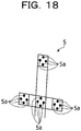
- FIG. 18 is a diagram illustrating an example of the vector marker.
- a user moves a vector marker 5 to a position at which the measurement ranges of the sensors overlap each other, and calculates the external parameter so that the positions of respective marks 5a of the vector marker coincide with each other for the sensors.
- Related Art 2 is an external calibration technique for calculating an external parameter of sensors using a lightweight spherical target.
- a plurality of sensors observe the spherical target a plurality of times while moving one spherical target.
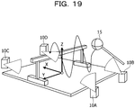
- FIG. 19 is a diagram for describing Related Art 2.
- sensors 10A, 10B, 10C, and 10D are arranged. External calibration of the sensors 10A to 10D is performed.
- a user moves a spherical target 15 attached to the tip of the hand-held rod in an action region.
- Each of the sensors 10A to 10D measures a three-dimensional point group of the spherical target 15 at regular time intervals.
- FIG. 20 is a diagram illustrating an example of the spherical target measured by each of the sensors.
- distributions da1, da2, da3, and da4 are set as distributions of three-dimensional point groups obtained by the sensor 10A measuring the spherical target 15 at time points t1, t2, t3, and t4.
- Distributions db1, db2, db3, and db4 are set as distributions of three-dimensional point groups obtained by the sensor 10B measuring the spherical target 15 at the time points t1, t2, t3, and t4.
- Distributions dc1, dc2, dc3, and dc4 are set as distributions of three-dimensional point groups obtained by the sensor 10C measuring the spherical target 15 at the time points t1, t2, t3, and t4.
- Distributions dd1, dd2, and dd3 are set as distributions of three-dimensional point groups obtained by the sensor 10D measuring the spherical target 15 at the time points t1, t2, and t3. It is assumed that the spherical target 15 is not included in a measurable range of the sensor 10D at the time point t4.
- FIG. 21 is a diagram for describing matching according to Related Art 2. As illustrated in FIG. 21 , in Related Art 2, a "t1 distribution" obtained by combining the distributions da1, db1, dc1, and dd1 at the time point t1 and a "t2 distribution” obtained by combining the distributions da2, db2, dc2, and dd2 at the time point t2 are generated.
- the external calibration is performed in a manner that the external parameters of the sensors 10A to 10D are adjusted so that the shapes of the t1 distribution to the t4 distribution are close to the shape of the spherical target 15.
- FIG. 22 is a diagram illustrating a result obtained by performing the external calibration.
- the external calibration is performed on six sensors, and a sphere is represented by combining distributions of three-dimensional point groups measured by the individual sensors at regular time intervals.
- the sphere is represented in a standard coordinate system.
- FIG. 23 is a diagram (1) for describing the problem of the related art.
- a sphere is represented in the standard coordinate system at regular time intervals, based on the measurement results of the sensors subjected to the external calibration.
- the sensor when the sensor has light reception distortion, at the end of the measurement range, distortion occurs in a target, and/or a shift in bonding occurs.
- a target In a three-dimensional point group 20a, distortion occurs in the target.
- a shift in the bonding occurs in the target.
- the noise is likely to be applied to the end of a detection object by the characteristics of a light receiving element of the sensor. For example, noise occurs in a three-dimensional point group 20d.
- FIG. 24 is a diagram (2) for describing the problem of the related art.
- a region A2 is a region common to the measurement ranges of the sensors 10A to 10D.
- the region A2 becomes the ends of the measurement regions of the sensors 10A to 10D.
- the number of samples decreases, and thus the estimation accuracy of the external parameter may rather decrease.
- an object of the present disclosure is to provide a calculation method, a calculation program, and an information processing apparatus with which accuracy of estimating a positional relationship between a plurality of sensors may be improved.
- a computer executes processing as follows.
- the computer acquires point groups of a target for each time point, that are measured using a plurality of sensors.
- the computer executes, for each time point, a process of, based on a first point group and a second point group, calculating a distance value indicating a distance between a center of the first point group and a center of the second point group, and calculating an error value indicating a degree of deviation between a surface of a sphere and the first point group and the second.
- the first point group indicates a point group of a target, that is measured using a first sensor among the plurality of sensors.
- the second point group indicates a point group of the target, that is measured using a second sensor among the plurality of sensors.
- the computer specifies an exclusion target point group that indicates a point group to be excluded, from the point groups of the target for each time point, based on the distance value and the error value calculated for each time point.
- the computer calculates information that indicates a positional relationship between the plurality of sensors by using a target point group that indicates a point group obtained by excluding the exclusion target point group from the point groups of the target for each time point.
- the accuracy of estimating the positional relationship between the plurality of sensors may be improved.
- FIG. 1 is a diagram illustrating an example of an information processing system according to an embodiment.
- an information processing system according to an embodiment includes sensors 10A, 10B, 10C, and 10D and an information processing apparatus 100.
- the sensors 10A to 10D and the information processing apparatus 100 are connected to each other in a wired or wireless manner.
- FIG. 1 illustrates the sensors 10A to 10D, but the information processing system may include other sensors.
- the sensor 10A is a measuring device (laser sensor) that measures the distance between the sensor 10A and a point group forming a subject (or target 2).
- the sensor 10A outputs data of a distance image being a measurement result to the information processing apparatus 100.
- the data of the distance image includes information in which each pixel is associated with a distance value.
- the data of the distance image is converted into three-dimensional point group data by the information processing apparatus 100.
- the three-dimensional point group data is information in which points are associated with coordinates in a three-dimensional orthogonal coordinate system for a point group. In the following description, the three-dimensional point group data is referred to as "point group data".
- the description related to the sensors 10B to 10D is similar to the description related to the sensor 10A.
- the sensors 10A to 10D are collectively referred to as "sensors 10" as appropriate.
- the point group data is data obtained by converting the data of the distance image measured by the sensor 10, but is appropriately referred to as point group data measured by the sensor 10, and description indicating that the data of the distance image is converted into the point group data will be omitted.
- the information processing system is a system that measures a subject (not illustrated) by using the sensor 10 and evaluates an action performed by the subject.
- the information processing system performs external calibration by using the target 2 and generates an external parameter, as pre-processing.
- the information processing system integrates the point group data measured by the sensor 10 based on the generated external parameter, generates point group data of the entirety of the subject, and evaluates the action performed by the subject.
- the information processing apparatus 100 calculates a "distance value" and an "error value” for the point group data of a target, which is measured by the sensor 10, and specifies point group data to be adopted in the external calibration, based on the calculation result. In this manner, the information processing apparatus improves the accuracy of the external parameter.
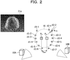
- FIG. 2 is a diagram (1) for describing the distance value and the error value.
- the point group data measured by the sensor 10A includes points d1-1 to d1-6.
- Point group data measured by the sensor 10B includes points d2-1 to d2-7.
- the points d1-1 to d1-6 and the points d2-1 to d2-7 are points obtained by simplifying a point group data 21a for explanation.
- the information processing apparatus 100 performs the external calibration by using the point group data measured by the sensor 10, and calculates an initial value of the external parameter. Therefore, it is assumed that the positions of the points d1-1 to d1-6 and the positions of the points d2-1 to d2-7 are adjusted by the initial value of the external parameter.
- the information processing apparatus 100 calculates a center position P A of a sphere estimated from the point group data (points d1-1 to d1-6) measured by the sensor 10A.
- the information processing apparatus 100 calculates a center position P B of a sphere estimated from the point group data (points d2-1 to d2-6) measured by the sensor 10B.
- the information processing apparatus 100 calculates a distance between the center position P A and the center position P B , as a distance value e gap .
- the information processing apparatus 100 performs fitting on a real sphere 16 based on the point group data measured by the sensor 10A and the point group data measured by the sensor 10B.
- the information processing apparatus 100 calculates a root mean square error of distances between the point group data (points d1-1 to d1-6 and points d2-1 to d2-6) and the surface of the real sphere 16, as an error value e rms .
- the information processing apparatus 100 specifies the point group data (points d1-1 to d1-6 and points d2-1 to d2-6) as point group data to be used in the external calibration.
- the information processing apparatus 100 specifies the point group data (points d1-1 to d1-6 and points d2-1 to d2-6) as point group data that is not used in the external calibration.
- e th1 and e th2 are thresholds set in advance.
- the point group data that is not used in the external calibration is referred to as "exclusion target point group data”.
- the exclusion target point group data is an example of an "exclusion target point group".
- the sensing result itself of the sensor 10 has the distortion in the point group data, that depends on the sensor individual difference, the sensor characteristics, and the environment.
- the distance value e gap does not satisfy the condition R1
- the error value e rms does not satisfy the condition R2.
- the point group data 21a in FIG. 2 distortion occurs in the target 2 formed by the point group data due to distortion of a light receiving lens of the sensors 10A and 10B.
- FIG. 3 is a diagram (2) for describing the distance value and the error value.
- point group data measured by the sensor 10A includes points d3-1 to d3-7.
- Point group data measured by the sensor 10B includes points d4-1 to d4-7.
- the points d3-1 to d3-7 and the points d4-1 to d4-7 are points obtained by simplifying a point group data 21b for explanation.
- the information processing apparatus 100 calculates the distance value e gap and the error value e rms based on the point group data (points d3-1 to d3-7 and points d4-1 to d4-7) in the similar manner to that in the case of FIG. 2 .
- the distance value e gap does not satisfy the condition R1
- the error value e rms does not satisfy the condition R2.
- a bonding shift occurs in the target 2 formed by the point group data due to the distortion of the light receiving lens of the sensors 10A and 10B.
- FIG. 4 is a diagram (3) for describing the distance value and the error value.
- point group data measured by the sensor 10A includes points d5-1 to d5-5.
- Point group data measured by the sensor 10B includes points d6-1 to d6-8.
- the points d5-1 to d5-5 and the points d6-1 to d6-8 are points obtained by simplifying a point group data 21c for explanation.
- the information processing apparatus 100 calculates the distance value e gap and the error value e rms based on the point group data (points d5-1 to d5-5 and points d6-1 to d6-8) in the similar manner to that in the case of FIG. 2 .
- the distance value e gap does not satisfy the condition R1.
- missing of a point group occurs in the target 2 formed by the point group data due to the characteristics and the like of the light receiving element of the sensors 10A and 10B.
- FIG. 5 is a diagram (4) for describing the distance value and the error value.
- point group data measured by the sensor 10A includes points d7-1 to d7-8.
- Point group data measured by the sensor 10B includes points d8-1 to d8-7.
- the points d7-1 to d7-8 and the points d8-1 to d8-7 are points obtained by simplifying a point group data 21d for explanation.
- the information processing apparatus 100 calculates the distance value e gap and the error value e rms based on the point group data (points d7-1 to d7-8 and points d8-1 to d8-7) in the similar manner to that in the case of FIG. 2 .
- the error value e rms does not satisfy the condition R2.
- noise occurs in the target 2 formed by the point group data due to the environmental factor and the like.
- the information processing apparatus 100 repeatedly executes the processing of calculating the distance value e gap and the error value e rms on the point group data of the target 2 measured by the sensors 10 at each time point.
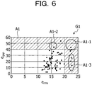
- FIG. 6 is a diagram illustrating a relationship between the distance value and the error value in the point group data at each time point.
- a horizontal axis is an axis corresponding to the error value e rms
- a vertical axis is an axis corresponding to the distance value e gap .
- Points illustrated in the graph G1 indicate a relationship between the distance value e gap and the error value e rms , which are calculated based on the point group data of the target 2 measured at a certain time point.
- a case where the point indicating the relationship between the distance value e gap and the error value e rms is included in a region A1, means that the point group data does not satisfy the condition R1 or the condition R2.
- point group data corresponding to this point has target distortion and bonding shift, such as the point group data 21a and the point group data 21b illustrated in FIGs. 2 and 3 .
- the information processing apparatus 100 repeatedly executes processing of updating the external parameter by performing the external calibration with point group data in which the point (point group data) indicating the relationship between the distance value e gap and the error value e rms is not included in the region A1.
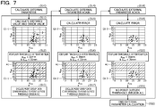
- FIG. 7 is a diagram for describing a change of the point group data used when the external parameter is updated.
- the information processing apparatus 100 calculates the external parameter (initial value of the external parameter) by using the point group data measured by the sensor 10 (step S10).
- the information processing apparatus 100 adjusts the position of the point group data at each time point based on the external parameter, and calculates the distance value and the error value (step S11).
- the relationship between the distance value and the error value of the point group data at each time point is represented in a graph G1-1.
- a horizontal axis of the graph G1-1 is an axis corresponding to the error value e rms
- a vertical axis is an axis corresponding to the distance value e gap .
- the description of the horizontal axis and the vertical axis of graphs G1-2 and G1-3 described later is similar to the description of the horizontal axis and the vertical axis of the graph G1-1.
- the information processing apparatus 100 performs threshold determination based on the distance value and the error value of the point group data at each time point (step S12). For example, the threshold e th1 is set to 30 mm, and the threshold e th2 is set to 20 mm.
- the information processing apparatus 100 excludes exclusion target point group data corresponding to points outside the threshold (region A1) (step S13).
- the information processing apparatus 100 estimates the external parameter again by using the remaining point group data (step S14).
- the information processing apparatus 100 adjusts the position of the point group data at each time point, based on the updated external parameter, and calculates the distance value and the error value (step S15).
- the relationship between the distance value and the error value of the point group data at each time point is represented in the graph G1-2.
- the information processing apparatus 100 performs threshold determination based on the distance value and the error value of the point group data at each time point (step S16). For example, the threshold e th1 is set to 30 mm, and the threshold e th2 is set to 20 mm.
- the information processing apparatus 100 excludes exclusion target point group data corresponding to points outside the threshold (region A1) (step S17).
- the information processing apparatus 100 estimates the external parameter again by using the remaining point group data (step S18).
- the information processing apparatus 100 adjusts the position of the point group data at each time point based on the updated external parameter, and calculates the distance value and the error value (step S19).
- the relationship between the distance value and the error value of the point group data at each time point is represented in the graph G1-3.
- step S21 Since there is no point outside the threshold (region A1) (step S21), the information processing apparatus 100 ends the calculation of the external parameter (step S22).
- the information processing apparatus 100 updates the external parameter by performing the external calibration with the point group data obtained by excluding the exclusion target point group data from the point group data measured by the sensor 10 at each time point.
- the information processing apparatus adjusts the position of the point group data by using the updated external parameter, and repeatedly executes the above-described processing until the exclusion target point group data is not detected any more.
- FIG. 8 is a functional block diagram illustrating the configuration of the information processing apparatus according to the embodiment.
- the information processing apparatus 100 includes a communication unit 110, an input unit 120, a display unit 130, a storage unit 140, and a control unit 150.
- the communication unit 110 is a processing unit that receives data of a distance image from the sensor 10 illustrated in FIG. 1 .
- the communication unit 110 outputs the received data of the distance image to the control unit 150.
- the communication unit 110 is an example of a communication device.
- the input unit 120 is an input device that inputs various types of information to the information processing apparatus 100.
- the input unit 120 corresponds to a keyboard, a mouse, a touch panel, or the like.
- the display unit 130 is a display device that displays information output from the control unit 150. For example, the display unit 130 displays skill recognition, scoring results, and the like of various competitions.
- the display unit 130 corresponds to a liquid crystal display, an organic electro-luminescence (EL) display, a touch panel, or the like.
- the storage unit 140 includes a background image table 141, a detection result table 142, and an external parameter table 143.
- the storage unit 140 corresponds to a semiconductor memory element such as a random-access memory (RAM) or a flash memory, or a storage device such as a hard disk drive (HDD).
- RAM random-access memory
- HDD hard disk drive
- the background image table 141 is a table that stores data of a background image (data of the distance image) measured by each of the sensors 10A to 10D in a state where there is no target 2.
- FIG. 9 is a diagram illustrating an example of a data structure of the background image table. As illustrated in FIG. 9 , in the background image table 141, sensor identification information is associated with the data of the background image. The sensor identification information is information for uniquely identifying the sensor.
- sensor identification information "SE10A” indicates the sensor 10A.
- Sensor identification information “SE10B” indicates the sensor 10B.
- Sensor identification information “SE10C” indicates the sensor 10C.
- Sensor identification information “SE10D” indicates the sensor 10D.
- the detection result table 142 is a table that stores the point group and the position of the target 2 detected at each time point, based on the measurement result of the sensor 10.
- FIG. 10 is a diagram illustrating an example of a data structure of the detection result table. As illustrated in FIG. 10 , the detection result table 142 stores the sensor identification information and point group data of the target 2 at each time point.
- the sensor identification information is information for uniquely identifying the sensor.
- the point group data of the target is data indicating a relationship between the point group of the target 2 and the three-dimensional coordinates of a point included in the point group at the corresponding time point t. In a case where no target is detected for the corresponding sensor identification information and time point, "no target" is stored.
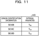
- the external parameter table 143 is a table that stores the external parameter calculated by an external parameter calculation unit 153 described later.
- FIG. 11 is a diagram illustrating an example of a data structure of the external parameter table. As illustrated in FIG. 11 , in the external parameter table 143, the sensor identification information is associated with the external parameter. The sensor identification information is information for identifying the sensor 10. The external parameter is data indicating the position and orientation relative to the sensor 10 being the reference. In the embodiment, it is assumed that the sensor being the reference is the sensor 10A.
- An external parameter T BA is data indicating the relative position and orientation of the sensor 10B with respect to the sensor 10A being the reference.
- An external parameter T CA is data indicating the relative position and orientation of the sensor 10C with respect to the sensor 10A being the reference.
- An external parameter T DA is data indicating the relative position and orientation of the sensor 10D with respect to the sensor 10A being the reference.
- the control unit 150 includes an acquisition unit 151, a conversion unit 152, the external parameter calculation unit 153, a calculation unit 154, a specifying unit 155, an integration unit 156, a fitting processing unit 157, and an evaluation unit 158.
- the control unit 150 is realized by any of a central processing unit (CPU), a microprocessor unit (MPU), a hardwired logic circuit such as an application-specific integrated circuit (ASIC) and a field-programmable gate array (FPGA), or the like.
- CPU central processing unit
- MPU microprocessor unit
- ASIC application-specific integrated circuit
- FPGA field-programmable gate array
- the acquisition unit 151 is a processing unit that acquires data of the distance image from the sensor 10 via the communication unit 110.
- the acquisition unit 151 acquires data of the distance image from the sensor 10 in advance in a state where the target 2 is not disposed, and registers the acquired data of the distance image in the background image table 141 as the data of the background image. It is assumed that the acquisition unit 151 registers the sensor identification information and the data of the background image in the background image table 141 in association with each other.
- the acquisition unit 151 acquires data of a plurality of continuous distance images from the sensor 10 and extracts data of the distance image at regular intervals.
- the user operates the input unit 120 to notify the information processing apparatus that the external calibration is to be performed, and then moves the target 2.
- FIG. 12 is a diagram for describing processing of the acquisition unit according to the embodiment. While the user is moving the target 2 along an action region, the sensor 10 measures a plurality of distance images (frames) at a predetermined frame rate (FPS: frames per second) and outputs data of the plurality of distance images in time series to the information processing apparatus 100 (acquisition unit 151). It is assumed that frame numbers are assigned to the data of the plurality of distance images in ascending order, and the frame numbers are synchronized in the sensors 10A to 10D. The frame number is a number for identifying the distance image.
- FPS frames per second
- the acquisition unit 151 sequentially acquires data of distance images having frame numbers f1 to f22 from the sensor 10A.
- data of a distance image having a frame number fn (n is a natural number) is referred to as a distance image fn.
- the acquisition unit 151 extracts distance images f3, f7, f11, f15, and f19 at regular intervals.
- the acquisition unit 151 extracts distance images f3, f7, f11, f15, and f19 at regular intervals for the sensors 10B to 10D in the similar manner.
- the acquisition unit 151 outputs data of the distance images extracted from the sensor 10 at the regular intervals, to the conversion unit 152.
- the conversion unit 152 is a processing unit that generates point group data at each time point based on the data of the distance image received from the acquisition unit 151.
- the conversion unit 152 registers the point group data at each time point in the detection result table 142 in association with the sensor identification information.
- the conversion unit 152 obtains a difference between the received data of the distance image and the data of the background image stored in the background image table 141 and generates background difference image data.
- the conversion unit 152 stores a conversion table in which a relationship between the position and the distance value of a pixel, and a point and the coordinates in the orthogonal coordinate system are defined.
- the conversion unit 152 converts pixels corresponding to the target 2, that are included in the background difference image data, into point group data, based on the conversion table.
- the conversion unit 152 repeatedly executes the above-described processing on the other extracted distance image fn to generate point group data at each time point and registers the generated point group data in the detection result table 142.
- the conversion unit 152 also generates point group data at each time point and registers the point group data in the detection result table 142, in a manner similar to that for the sensor 10A.
- the external parameter calculation unit 153 calculates the external parameters T BA , T CA , and T DA based on the point group data at each time point included in the detection result table 142, and registers the calculated external parameters T BA , T CA , and T DA in the external parameter table 143. In a case where the external parameters T BA , T CA , and T DA are already registered in the external parameter table 143, the external parameter calculation unit 153 updates the external parameters T BA , T CA , and T DA with the newly-calculated external parameters T BA , T CA , and T DA .
- the external parameter calculation unit 153 acquires the point group data measured by the sensor 10 at each time point from the detection result table 142, and calculates the external parameters T BA , T CA , and T DA so that the shape represented by the point group data at each time point is close to the shape of a sphere.
- the position of a point in the point group data is adjusted in accordance with a change in the external parameters T BA , T CA , and T DA . Any technique may be used for the processing in which the external parameter calculation unit 153 calculates the external parameters by using the point group data at each time point.
- the external parameter calculation unit 153 calculates an initial value of the external parameter.
- the external parameter calculation unit 153 repeatedly executes the processing of calculating the external parameter and updates the external parameter table 143, each time the exclusion target point group data is excluded from the point group data in the detection result table 142 by the specifying unit 155 described later.
- the external parameter calculation unit 153 may adjust the position of the point group data stored in the detection result table 142, based on the external parameters T BA , T CA , and T DA . In a case where the point group data is not excluded any more from the point group data in the detection result table 142, the external parameter calculation unit 153 ends the processing of calculating the external parameter.
- the calculation unit 154 is a processing unit that calculates the distance value e gap and the error value e rms described in FIGs. 2 to 5 .
- the calculation unit 154 outputs information of the distance value e gap and the error value e rms calculated from the point group data at each time point, to the specifying unit 155.
- An example of processing of the calculation unit 154 will be described below.
- the calculation unit 154 calculates the distance value based on the point group data subjected to position adjustment.
- the processing in which the calculation unit 154 calculates the distance value will be described with reference to FIG. 2 .
- the calculation unit 154 calculates the center position P A of a sphere estimated from the point group data (points d1-1 to d1-6) measured by the sensor 10A.
- the information processing apparatus 100 calculates a center position P B of a sphere estimated from the point group data (points d2-1 to d2-6) measured by the sensor 10B.
- the calculation unit 154 calculates the distance between the center position P A and the center position P B , as the distance value e gap .
- FIG. 13 is a diagram for describing processing in which the calculation unit calculates the error value e rms .
- FIG. 13 illustrates the point group data measured by the sensors 10A and 10B, but the embodiment is not limited to this.
- the calculation unit 154 calculates the error value e rms based on expression (1).
- e i represents a distance from the real spherical surface of the real sphere 16 to a point. The outside of the spherical surface is set to being positive, and the inside of the spherical surface is set to being negative.
- the calculation unit 154 calculates the root mean square error as the error value e rms , but the error value e rms is not limited to this.
- the calculation unit 154 Each time the external parameter stored in the external parameter table 143 is updated, the calculation unit 154 repeatedly executes the processing of calculating the distance value e gap and the error value e rms at each time point, and outputs the distance value e gap and the error value e rms to the specifying unit 155.
- the specifying unit 155 is a processing unit that specifies the exclusion target point group data based on the distance value e gap and the error value e rms at each time point.
- the specifying unit 155 deletes the specified exclusion target point group data from the detection result table 142. An example of processing of the specifying unit 155 will be described below.
- the remaining point group data obtained by removing the exclusion target point group data from the point group data in the detection result table 142 corresponds to a "target point group".
- the specifying unit 155 is a processing unit that specifies the exclusion target point group data based on the distance value e gap and the error value e rms calculated from the point group data at each time point.
- the specifying unit 155 repeatedly executes the above-described processing on the point group data at each time point, to specify the exclusion target point group from the point group data at each time point.
- the specifying unit 155 excludes the exclusion target point group data from the detection result table 142.
- the specifying unit 155 In a case where the specifying unit 155 specifies the exclusion target point group data from the point group data at each time point, the specifying unit 155 notifies the external parameter calculation unit 153 that the exclusion target point group data is included. The specifying unit 155 repeatedly executes the above-described processing each time the new distance value e gap and the new error value e rms calculated from the point group data at each time point are acquired from the calculation unit 154.
- the integration unit 156, the fitting processing unit 157, and the evaluation unit 158 execute processing in a case where the external calibration by the acquisition unit 151, the conversion unit 152, the external parameter calculation unit 153, the calculation unit 154, and the specifying unit 155 ends and the subject starts an action.
- the integration unit 156 acquires the point group data corresponding to the sensor 10, from the conversion unit 152.
- the integration unit 156 adjusts the point group data of the sensors 10B to 10C in accordance with the position and orientation of the sensor 10A. For example, the integration unit 156 aligns the point group data of the sensor 10B with the position and orientation of the sensor 10A by using the external parameter T BA .
- the integration unit 156 aligns the point group data of the sensor 10C with the position and orientation of the sensor 10A by using the external parameter T CA .
- the integration unit 156 aligns the point group data of the sensor 10D with the position and orientation of the sensor 10A by using the external parameter T DA .
- the integration unit 156 acquires each external parameter from the external parameter table 143.
- the integration unit 156 integrates the point group data of the sensor 10A and the point group data of the sensors 10B to 10D, that is aligned with the position and orientation of the sensor 10A, and generates one piece of point group data.
- the integration unit 156 outputs the generated point group data to the fitting processing unit 157.
- the integration unit 156 repeatedly executes the above-described processing each time the point group data of the sensors 10A to 10D is acquired from the conversion unit 152.
- the fitting processing unit 157 is a processing unit that performs fitting for fitting three-dimensional model data of the subject to the point group data.
- the fitting processing unit 157 specifies skeleton model data of the subject based on the fitting result.
- the skeleton model data includes position information of each joint.
- the fitting processing unit outputs the skeleton model data to the evaluation unit 158.
- the fitting processing unit repeatedly executes the above-described processing each time the point group data is acquired from the integration unit 156.
- the evaluation unit 158 is a processing unit that acquires the skeleton model data in time series and evaluates the action of the subject based on the transition of coordinates of each joint of the skeleton model data. For example, the evaluation unit 158 evaluates the action of the subject by using the transition of the coordinates of each joint and a table (not illustrated) in which the type of the action and the success or failure of establishment of the action are defined. Then, the evaluation unit 158 outputs the evaluation result to the display unit 130 and cause the display unit 130 to display the evaluation result.
- the evaluation of the action is applicable to various scoring competitions.
- the scoring competitions include, in addition to the gymnastics, a trampoline, a jump in swimming, figure skating, standard moves of karate, ballroom dance, snowboarding, skateboarding, skiing aerial, and surfing.
- the embodiment may also be applied to a form check or the like for classical ballet, ski-jump, mogul air, turning, baseball, or basketball.
- the evaluation of the action may also be applied to competitions such as kendo, judo, wrestling, and sumo.
- the evaluation of the action may also be used to evaluate whether or not the barbell for weight lifting is raised.
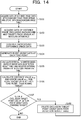
- FIG. 14 is a flowchart illustrating the processing procedure of the processing in which the information processing apparatus according to the embodiment performs external calibration.
- the acquisition unit 151 in the information processing apparatus 100 acquires data of the distance image (data of the background image) from the sensor 10 and stores the acquired data of the distance image in the background image table 141 (step S101).
- the acquisition unit 151 acquires data of the distance image (including the background and the target) from the sensor 10 at regular intervals (step S102).
- the conversion unit 152 in the information processing apparatus 100 generates background difference data based on the data of the background image and the data of the distance image (step S103).
- the conversion unit 152 generates point group data at each time point (step S104).
- the external parameter calculation unit 153 in the information processing apparatus 100 calculates the external parameter based on the point group data in the detection result table 142 and registers the external parameter in the external parameter table 143 (step S105).
- the calculation unit 154 in the information processing apparatus 100 calculates the distance value e gap and the error value e rms for the point group data at each time point forming the target (step S106).
- the specifying unit 155 in the information processing apparatus 100 determines whether or not there is the exclusion target point group data in the point group data forming the target (step S107).
- the specifying unit 155 deletes the exclusion target point group data from the detection result table (step S108), and causes the process to proceed to step S105.
- the information processing apparatus 100 ends the external calibration.
- the information processing apparatus 100 updates the external parameters by performing the external calibration with the point group data obtained by excluding the exclusion target point group data from the point group data measured by the sensor 10 at each time point.
- the information processing apparatus 100 adjusts the position of the point group data by using the updated external parameter, and repeatedly executes the above-described processing until the exclusion target point group data is not detected any more.
- FIG. 15 is a diagram illustrating an example in which the processing of the information processing apparatus is applied to the point group data at each time point.
- the information processing apparatus 100 executes the processing on each piece of point group data 50a, and thus the pieces of the point group data 21a, 21b, and 21c are specified as the exclusion target point group data, and point group data 50b remains.
- the accuracy of estimating the external parameter is improved by performing the external calibration with the point group data 50b.
- the information processing apparatus 100 specifies the exclusion target point group data by using both the condition R1 and the condition R2, but the embodiment is not limited to this.
- the information processing apparatus 100 may calculate only the distance value e gap of the point group data at each time point, determine whether or not the distance value e gap satisfies the condition R1, and specify the point group data that does not satisfy the condition R1, as the exclusion target point group data.
- the information processing apparatus 100 may calculate only the error value e rms of the point group data at each time point, determine whether or not the error value e rms satisfies the condition R2, and specify the point group data that does not satisfy the condition R2, as the exclusion target point group data.
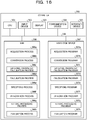
- FIG. 16 is a diagram illustrating an example of a hardware configuration of a computer that implements functions similar to those of the information processing apparatus.
- a computer 300 includes a CPU 301 that executes various types of arithmetic processing, an input device 302 that receives an input of data from the user, and a display 303.
- the computer 300 also includes a communication device 304 that receives the data of the distance image from the sensor 10, and an interface device 305 coupled to various devices.
- the computer 300 includes a RAM 306 that temporarily stores various types of information, and a hard disk device 307. Each of devices (the CPU 301 to the hard disk device 307) is coupled to a bus 308.
- the hard disk device 307 includes an acquisition program 307a, a conversion program 307b, an external parameter calculation program 307c, a calculation program 307d, and a specifying program 307e.
- the hard disk device 307 includes an integration program 307f, a fitting processing program 307g, and an evaluation program 307h.
- the CPU 301 reads the acquisition program 307a, the conversion program 307b, the external parameter calculation program 307c, the calculation program 307d, the specifying program 307e, the integration program 307f, the fitting processing program 307g, and the evaluation program 307h and loads the programs into the RAM 306.
- the acquisition program 307a functions as an acquisition process 306a.
- the conversion program 307b functions as a conversion process 306b.
- the external parameter calculation program 307c functions as an external parameter calculation process 306c.
- the calculation program 307d functions as a calculation process 306d.
- the specifying program 307e functions as a specifying process 306e.
- the integration program 307f functions as an integration process 306f.
- the fitting processing program 307g functions as a fitting processing process 306g.
- the evaluation program 307h functions as an evaluation process 306h.
- Processing of the acquisition process 306a corresponds to the processing of the acquisition unit 151.
- Processing of the conversion process 306b corresponds to the processing of the conversion unit 152.
- Processing of the external parameter calculation process 306c corresponds to the processing of the external parameter calculation unit 153.
- Processing of the calculation process 306d corresponds to the processing of the calculation units 154.
- Processing of the specifying process 306e corresponds to the processing of the specifying unit 155.
- Processing of the integration process 306f corresponds to the processing of the integration unit 156.
- Processing of the fitting processing process 306g corresponds to the processing of the fitting processing unit 157.
- Processing of the evaluation process 306h corresponds to the processing of the evaluation unit 158.
- the acquisition program 307a to the evaluation program 307h do not necessarily have to be stored in the hard disk device 307 from the beginning.
- the programs may be stored in a "portable physical medium" to be inserted into the computer 300, such as a flexible disk (FD), a compact disc read-only memory (CD-ROM), a digital versatile disc (DVD), a magneto-optical disc, or an IC card.
- the computer 300 may read and execute the acquisition program 307a to the evaluation program 307h.
Landscapes
- Engineering & Computer Science (AREA)
- Physics & Mathematics (AREA)
- General Physics & Mathematics (AREA)
- Theoretical Computer Science (AREA)
- Computer Vision & Pattern Recognition (AREA)
- Electromagnetism (AREA)
- Computer Networks & Wireless Communication (AREA)
- Remote Sensing (AREA)
- Radar, Positioning & Navigation (AREA)
- Computational Mathematics (AREA)
- Pure & Applied Mathematics (AREA)
- Data Mining & Analysis (AREA)
- Mathematical Physics (AREA)
- Mathematical Analysis (AREA)
- Mathematical Optimization (AREA)
- Databases & Information Systems (AREA)
- General Engineering & Computer Science (AREA)
- Software Systems (AREA)
- Algebra (AREA)
- Optics & Photonics (AREA)
- Length Measuring Devices By Optical Means (AREA)
- Length Measuring Devices With Unspecified Measuring Means (AREA)
- Traffic Control Systems (AREA)
- Image Analysis (AREA)
Abstract
Description
- The embodiment discussed herein is related to a calculation method and the like.
- There is a technique in the related art for measuring a three-dimensional point group of a subject using a distance measuring device such as a laser sensor. In the following description, the distance measuring device such as the laser sensor is referred to as a "sensor". For example, it is possible to three-dimensionally reproduce a subject by sensing the subject from each direction using a plurality of sensors arranged around the subject and integrating three-dimensional point groups as measurement results of the sensors.
-
FIG. 17 is a diagram illustrating a result obtained by integrating three-dimensional point groups measured by a plurality of sensors. In the example illustrated inFIG. 17 ,sensors subject 1. Thesensors 10A to 10D measure thesubject 1 and obtain three-dimensional point groups. - A three-
dimensional point group 11A is data based on the measurement result of thesensor 10A. A three-dimensional point group 11B is data based on the measurement result of thesensor 10B. A three-dimensional point group 11C is data based on the measurement result of thesensor 10C. A three-dimensional point group 11D is data based on the measurement result of thesensor 10D. A three-dimensional point group 12 is generated by integrating the three-dimensional point groups 11A to 11D. The three-dimensional point group 12 is used for three-dimensionally reproducing thesubject 1. - In a case where a plurality of three-dimensional point groups are integrated, an external parameter is used. The external parameter is information indicating a positional relationship between the plurality of sensors. Examples of the related art for calculating the external parameter include
Related Arts -
Related Art 1 will be described.Related Art 1 is an external calibration technique for calculating an external parameter of sensors using a vector marker.FIG. 18 is a diagram illustrating an example of the vector marker. A user moves avector marker 5 to a position at which the measurement ranges of the sensors overlap each other, and calculates the external parameter so that the positions ofrespective marks 5a of the vector marker coincide with each other for the sensors. - In
Related Art 1, thevector marker 5 is heavy. Thus, a burden on the user is large. The accuracy of the external parameter calculated byRelated Art 1 is poor, which is coped with by the user manually performing fine adjustment of the external parameter after the estimation of the external parameter. There isRelated Art 2 for the problem ofRelated Art 1. -
Related Art 2 will be described.Related Art 2 is an external calibration technique for calculating an external parameter of sensors using a lightweight spherical target. InRelated Art 2, a plurality of sensors observe the spherical target a plurality of times while moving one spherical target. -
FIG. 19 is a diagram for describingRelated Art 2. In the example illustrated inFIG. 19 ,sensors sensors 10A to 10D is performed. A user moves aspherical target 15 attached to the tip of the hand-held rod in an action region. - Each of the
sensors 10A to 10D measures a three-dimensional point group of thespherical target 15 at regular time intervals.FIG. 20 is a diagram illustrating an example of the spherical target measured by each of the sensors. For example, distributions da1, da2, da3, and da4 are set as distributions of three-dimensional point groups obtained by thesensor 10A measuring thespherical target 15 at time points t1, t2, t3, and t4. Distributions db1, db2, db3, and db4 are set as distributions of three-dimensional point groups obtained by thesensor 10B measuring thespherical target 15 at the time points t1, t2, t3, and t4. - Distributions dc1, dc2, dc3, and dc4 are set as distributions of three-dimensional point groups obtained by the
sensor 10C measuring thespherical target 15 at the time points t1, t2, t3, and t4. Distributions dd1, dd2, and dd3 are set as distributions of three-dimensional point groups obtained by thesensor 10D measuring thespherical target 15 at the time points t1, t2, and t3. It is assumed that thespherical target 15 is not included in a measurable range of thesensor 10D at the time point t4. - In
Related Art 2, an external parameter is calculated by capturing the center of thespherical target 15 measured by thesensors 10A to 10D at each time point and matching the center between thesensors 10A to 10D.FIG. 21 is a diagram for describing matching according toRelated Art 2. As illustrated inFIG. 21 , inRelated Art 2, a "t1 distribution" obtained by combining the distributions da1, db1, dc1, and dd1 at the time point t1 and a "t2 distribution" obtained by combining the distributions da2, db2, dc2, and dd2 at the time point t2 are generated. InRelated Art 2, a "t3 distribution" obtained by combining the distributions da3, db3, dc3, and dd3 at the time point t3 and a "t4 distribution" obtained by combining the distributions da4, db4, and dc4 at the time point t4 are generated. - In
Related Art 2, the external calibration is performed in a manner that the external parameters of thesensors 10A to 10D are adjusted so that the shapes of the t1 distribution to the t4 distribution are close to the shape of thespherical target 15. -
FIG. 22 is a diagram illustrating a result obtained by performing the external calibration. InFIG. 22 , as an example, the external calibration is performed on six sensors, and a sphere is represented by combining distributions of three-dimensional point groups measured by the individual sensors at regular time intervals. InFIG. 22 , the sphere is represented in a standard coordinate system. - [PTL 1] Japanese Laid-open Patent Publication No.
2019-086476 - [NPL 1] M. Ruan, "Calibration of 3D Sensors Using a Spherical Target", 3DV 2014
- In
Related Art 2, since it is sufficient to move the lightweightspherical target 15, the burden on the user is smaller than in a case where thevector marker 5 is moved as inRelated Art 1. InRelated Art 2, it is possible to calculate the external parameter with a certain degree of accuracy without manually performing fine adjustment of the external parameter as inRelated Art 1. - However, if the sensing result itself of each of the sensors includes the distortion in the three-dimensional point group that depends on the sensor individual difference, the sensor characteristics, and the environment, there is a problem that the estimation accuracy of the external parameter decreases even when
Related Art 2 is used. -
FIG. 23 is a diagram (1) for describing the problem of the related art. InFIG. 23 , a sphere is represented in the standard coordinate system at regular time intervals, based on the measurement results of the sensors subjected to the external calibration. - For example, when the sensor has light reception distortion, at the end of the measurement range, distortion occurs in a target, and/or a shift in bonding occurs. In a three-
dimensional point group 20a, distortion occurs in the target. In a three-dimensional point group 20b, a shift in the bonding occurs in the target. - The noise is likely to be applied to the end of a detection object by the characteristics of a light receiving element of the sensor. For example, noise occurs in a three-
dimensional point group 20d. - As a case depending on the environment, data loss occurs in a case of being influenced by an obstacle or if the detection object is located at the end of the measurement range. In a three-
dimensional point group 20c, missing of a point group occurs. -
FIG. 24 is a diagram (2) for describing the problem of the related art. For example, in order to exclude the influence of noise distortion, it is considered to exclude the targets at the ends of the measurement range. In a case wheresensors 10A to 10D are arranged as illustrated inFIG. 24 , a region A2 is a region common to the measurement ranges of thesensors 10A to 10D. In such a case, the region A2 becomes the ends of the measurement regions of thesensors 10A to 10D. However, if a target in the region A2 is simply excluded, the number of samples decreases, and thus the estimation accuracy of the external parameter may rather decrease. - In one aspect, an object of the present disclosure is to provide a calculation method, a calculation program, and an information processing apparatus with which accuracy of estimating a positional relationship between a plurality of sensors may be improved.
- In a first aspect, a computer executes processing as follows. The computer acquires point groups of a target for each time point, that are measured using a plurality of sensors. The computer executes, for each time point, a process of, based on a first point group and a second point group, calculating a distance value indicating a distance between a center of the first point group and a center of the second point group, and calculating an error value indicating a degree of deviation between a surface of a sphere and the first point group and the second. The first point group indicates a point group of a target, that is measured using a first sensor among the plurality of sensors. The second point group indicates a point group of the target, that is measured using a second sensor among the plurality of sensors. The computer specifies an exclusion target point group that indicates a point group to be excluded, from the point groups of the target for each time point, based on the distance value and the error value calculated for each time point. The computer calculates information that indicates a positional relationship between the plurality of sensors by using a target point group that indicates a point group obtained by excluding the exclusion target point group from the point groups of the target for each time point.
- The accuracy of estimating the positional relationship between the plurality of sensors may be improved.
-
-
FIG. 1 is a diagram illustrating an example of an information processing system according to an embodiment; -
FIG. 2 is a diagram (1) for describing a distance value and an error value; -
FIG. 3 is a diagram (2) for describing the distance value and the error value; -
FIG. 4 is a diagram (3) for describing the distance value and the error value; -
FIG. 5 is a diagram (4) for describing the distance value and the error value; -
FIG. 6 is a diagram illustrating a relationship between the distance value and the error value in point group data at each time point; -
FIG. 7 is a diagram for describing a change of the point group data used when an external parameter is updated; -
FIG. 8 is a functional block diagram illustrating a configuration of an information processing apparatus according to the embodiment; -
FIG. 9 is a diagram illustrating an example of a data structure of a background image table; -
FIG. 10 is a diagram illustrating an example of a data structure of a detection result table; -
FIG. 11 is a diagram illustrating an example of a data structure of an external parameter table; -
FIG. 12 is a diagram for describing processing of an acquisition unit according to the embodiment; -
FIG. 13 is a diagram for describing processing in which a calculation unit calculates an error value erms; -
FIG. 14 is a flowchart illustrating a processing procedure of processing in which the information processing apparatus according to the embodiment performs external calibration; -
FIG. 15 is a diagram illustrating an example in which processing of the information processing apparatus is applied to the point group data at each time point; -
FIG. 16 is a diagram illustrating an example of a hardware configuration of a computer that implements functions similar to those of the information processing apparatus; -
FIG. 17 is a diagram illustrating a result obtained by integrating three-dimensional point groups measured by a plurality of sensors; -
FIG. 18 is a diagram illustrating an example of a vector marker; -
FIG. 19 is a diagram for describingRelated Art 2; -
FIG. 20 is a diagram illustrating an example of a spherical target measured by each sensor; -
FIG. 21 is a diagram for describing matching according toRelated Art 2; -
FIG. 22 is a diagram illustrating a result obtained by performing external calibration; -
FIG. 23 is a diagram (1) for describing a problem of the related art; and -
FIG. 24 is a diagram (2) for describing the problem of the related art. - Hereinafter, a calculation method, a calculation program, and an information processing apparatus according to an embodiment disclosed in the present application will be described in detail with reference to the drawings. The present disclosure is not limited to the embodiment.
-
FIG. 1 is a diagram illustrating an example of an information processing system according to an embodiment. As illustrated inFIG. 1 , an information processing system according to an embodiment includessensors information processing apparatus 100. Thesensors 10A to 10D and theinformation processing apparatus 100 are connected to each other in a wired or wireless manner.FIG. 1 illustrates thesensors 10A to 10D, but the information processing system may include other sensors. - The
sensor 10A is a measuring device (laser sensor) that measures the distance between thesensor 10A and a point group forming a subject (or target 2). Thesensor 10A outputs data of a distance image being a measurement result to theinformation processing apparatus 100. The data of the distance image includes information in which each pixel is associated with a distance value. The data of the distance image is converted into three-dimensional point group data by theinformation processing apparatus 100. The three-dimensional point group data is information in which points are associated with coordinates in a three-dimensional orthogonal coordinate system for a point group. In the following description, the three-dimensional point group data is referred to as "point group data". - The description related to the
sensors 10B to 10D is similar to the description related to thesensor 10A. In the following description, thesensors 10A to 10D are collectively referred to as "sensors 10" as appropriate. The point group data is data obtained by converting the data of the distance image measured by thesensor 10, but is appropriately referred to as point group data measured by thesensor 10, and description indicating that the data of the distance image is converted into the point group data will be omitted. - The information processing system according to the embodiment is a system that measures a subject (not illustrated) by using the
sensor 10 and evaluates an action performed by the subject. The information processing system performs external calibration by using thetarget 2 and generates an external parameter, as pre-processing. The information processing system integrates the point group data measured by thesensor 10 based on the generated external parameter, generates point group data of the entirety of the subject, and evaluates the action performed by the subject. - An example of processing in which the
information processing apparatus 100 in the information processing system calculates the external parameter will be described. Theinformation processing apparatus 100 calculates a "distance value" and an "error value" for the point group data of a target, which is measured by thesensor 10, and specifies point group data to be adopted in the external calibration, based on the calculation result. In this manner, the information processing apparatus improves the accuracy of the external parameter. -
FIG. 2 is a diagram (1) for describing the distance value and the error value. In the example illustrated inFIG. 2 , the point group data measured by thesensor 10A includes points d1-1 to d1-6. Point group data measured by thesensor 10B includes points d2-1 to d2-7. The points d1-1 to d1-6 and the points d2-1 to d2-7 are points obtained by simplifying apoint group data 21a for explanation. - The
information processing apparatus 100 performs the external calibration by using the point group data measured by thesensor 10, and calculates an initial value of the external parameter. Therefore, it is assumed that the positions of the points d1-1 to d1-6 and the positions of the points d2-1 to d2-7 are adjusted by the initial value of the external parameter. - The
information processing apparatus 100 calculates a center position PA of a sphere estimated from the point group data (points d1-1 to d1-6) measured by thesensor 10A. Theinformation processing apparatus 100 calculates a center position PB of a sphere estimated from the point group data (points d2-1 to d2-6) measured by thesensor 10B. Theinformation processing apparatus 100 calculates a distance between the center position PA and the center position PB, as a distance value egap. - The
information processing apparatus 100 performs fitting on areal sphere 16 based on the point group data measured by thesensor 10A and the point group data measured by thesensor 10B. Theinformation processing apparatus 100 calculates a root mean square error of distances between the point group data (points d1-1 to d1-6 and points d2-1 to d2-6) and the surface of thereal sphere 16, as an error value erms. - In a case where the distance value egap satisfies a condition R1 and the error value erms satisfies a condition R2, the
information processing apparatus 100 specifies the point group data (points d1-1 to d1-6 and points d2-1 to d2-6) as point group data to be used in the external calibration. In a case where the distance value egap does not satisfy the condition R1 or the error value erms does not satisfy the condition R2, theinformation processing apparatus 100 specifies the point group data (points d1-1 to d1-6 and points d2-1 to d2-6) as point group data that is not used in the external calibration. eth1 and eth2 are thresholds set in advance. In the following description, the point group data that is not used in the external calibration is referred to as "exclusion target point group data". The exclusion target point group data is an example of an "exclusion target point group". - Distance value egap < eth1 ... Condition R1
- Error value erms < eth2 ... Condition R2
- In a case where the distance value egap does not satisfy the condition R1, or in a case where the error value erms does not satisfy the condition R2, the sensing result itself of the
sensor 10 has the distortion in the point group data, that depends on the sensor individual difference, the sensor characteristics, and the environment. - For example, in the case of the point group data (points d1-1 to d1-6 and points d2-1 to d2-6) illustrated in
FIG. 2 , the distance value egap does not satisfy the condition R1, and the error value erms does not satisfy the condition R2. In thepoint group data 21a inFIG. 2 , distortion occurs in thetarget 2 formed by the point group data due to distortion of a light receiving lens of thesensors -
FIG. 3 is a diagram (2) for describing the distance value and the error value. In the example illustrated inFIG. 3 , point group data measured by thesensor 10A includes points d3-1 to d3-7. Point group data measured by thesensor 10B includes points d4-1 to d4-7. The points d3-1 to d3-7 and the points d4-1 to d4-7 are points obtained by simplifying apoint group data 21b for explanation. - The
information processing apparatus 100 calculates the distance value egap and the error value erms based on the point group data (points d3-1 to d3-7 and points d4-1 to d4-7) in the similar manner to that in the case ofFIG. 2 . For example, in the case of the point group data (points d3-1 to d3-7 and points d4-1 to d4-7) illustrated inFIG. 3 , the distance value egap does not satisfy the condition R1, and the error value erms does not satisfy the condition R2. In thepoint group data 21b inFIG. 3 , a bonding shift occurs in thetarget 2 formed by the point group data due to the distortion of the light receiving lens of thesensors -
FIG. 4 is a diagram (3) for describing the distance value and the error value. In the example illustrated inFIG. 4 , point group data measured by thesensor 10A includes points d5-1 to d5-5. Point group data measured by thesensor 10B includes points d6-1 to d6-8. The points d5-1 to d5-5 and the points d6-1 to d6-8 are points obtained by simplifying apoint group data 21c for explanation. - The
information processing apparatus 100 calculates the distance value egap and the error value erms based on the point group data (points d5-1 to d5-5 and points d6-1 to d6-8) in the similar manner to that in the case ofFIG. 2 . For example, in the case of the point group data (points d5-1 to d5-5 and points d6-1 to d6-8) illustrated inFIG. 4 , the distance value egap does not satisfy the condition R1. In thepoint group data 21c inFIG. 4 , missing of a point group occurs in thetarget 2 formed by the point group data due to the characteristics and the like of the light receiving element of thesensors -
FIG. 5 is a diagram (4) for describing the distance value and the error value. In the example illustrated inFIG. 5 , point group data measured by thesensor 10A includes points d7-1 to d7-8. Point group data measured by thesensor 10B includes points d8-1 to d8-7. The points d7-1 to d7-8 and the points d8-1 to d8-7 are points obtained by simplifying apoint group data 21d for explanation. - The
information processing apparatus 100 calculates the distance value egap and the error value erms based on the point group data (points d7-1 to d7-8 and points d8-1 to d8-7) in the similar manner to that in the case ofFIG. 2 . For example, in the case of the point group data (points d7-1 to d7-8 and points d8-1 to d8-7) illustrated inFIG. 5 , the error value erms does not satisfy the condition R2. In thepoint group data 21d inFIG. 5 , noise occurs in thetarget 2 formed by the point group data due to the environmental factor and the like. - The
information processing apparatus 100 repeatedly executes the processing of calculating the distance value egap and the error value erms on the point group data of thetarget 2 measured by thesensors 10 at each time point. -
FIG. 6 is a diagram illustrating a relationship between the distance value and the error value in the point group data at each time point. In a graph G1 inFIG. 6 , a horizontal axis is an axis corresponding to the error value erms, and a vertical axis is an axis corresponding to the distance value egap. Points illustrated in the graph G1 indicate a relationship between the distance value egap and the error value erms, which are calculated based on the point group data of thetarget 2 measured at a certain time point. - A case where the point indicating the relationship between the distance value egap and the error value erms is included in a region A1, means that the point group data does not satisfy the condition R1 or the condition R2. For example, in a case where a point is included in a region A1-1, point group data corresponding to this point has target distortion and bonding shift, such as the
point group data 21a and thepoint group data 21b illustrated inFIGs. 2 and3 . - In a case where a point is included in a region A1-2, missing of a point group occurs in point group data corresponding to this point, such as the
point group data 21c illustrated inFIG. 4 . In a case where a point is included in a region A1-3, noise occurs in point group data corresponding to this point, such as thepoint group data 21d illustrated inFIG. 5 . - The
information processing apparatus 100 repeatedly executes processing of updating the external parameter by performing the external calibration with point group data in which the point (point group data) indicating the relationship between the distance value egap and the error value erms is not included in the region A1. -
FIG. 7 is a diagram for describing a change of the point group data used when the external parameter is updated. As illustrated inFIG. 7 , theinformation processing apparatus 100 calculates the external parameter (initial value of the external parameter) by using the point group data measured by the sensor 10 (step S10). Theinformation processing apparatus 100 adjusts the position of the point group data at each time point based on the external parameter, and calculates the distance value and the error value (step S11). The relationship between the distance value and the error value of the point group data at each time point is represented in a graph G1-1. A horizontal axis of the graph G1-1 is an axis corresponding to the error value erms, and a vertical axis is an axis corresponding to the distance value egap. The description of the horizontal axis and the vertical axis of graphs G1-2 and G1-3 described later is similar to the description of the horizontal axis and the vertical axis of the graph G1-1. - The
information processing apparatus 100 performs threshold determination based on the distance value and the error value of the point group data at each time point (step S12). For example, the threshold eth1 is set to 30 mm, and the threshold eth2 is set to 20 mm. Theinformation processing apparatus 100 excludes exclusion target point group data corresponding to points outside the threshold (region A1) (step S13). - The
information processing apparatus 100 estimates the external parameter again by using the remaining point group data (step S14). Theinformation processing apparatus 100 adjusts the position of the point group data at each time point, based on the updated external parameter, and calculates the distance value and the error value (step S15). The relationship between the distance value and the error value of the point group data at each time point is represented in the graph G1-2. - The
information processing apparatus 100 performs threshold determination based on the distance value and the error value of the point group data at each time point (step S16). For example, the threshold eth1 is set to 30 mm, and the threshold eth2 is set to 20 mm. Theinformation processing apparatus 100 excludes exclusion target point group data corresponding to points outside the threshold (region A1) (step S17). - The
information processing apparatus 100 estimates the external parameter again by using the remaining point group data (step S18). Theinformation processing apparatus 100 adjusts the position of the point group data at each time point based on the updated external parameter, and calculates the distance value and the error value (step S19). The relationship between the distance value and the error value of the point group data at each time point is represented in the graph G1-3. - Since there is no point outside the threshold (region A1) (step S21), the
information processing apparatus 100 ends the calculation of the external parameter (step S22). - As described above, the
information processing apparatus 100 according to the embodiment updates the external parameter by performing the external calibration with the point group data obtained by excluding the exclusion target point group data from the point group data measured by thesensor 10 at each time point. The information processing apparatus adjusts the position of the point group data by using the updated external parameter, and repeatedly executes the above-described processing until the exclusion target point group data is not detected any more. Thus, it is possible to perform the external calibration by using the point group data obtained by excluding the point group data depending on the sensor individual difference, the sensor characteristics, and the environment, and to improve the accuracy of estimating the positional relationship between the plurality of sensors. - Next, a configuration of the
information processing apparatus 100 illustrated inFIG. 1 will be described.FIG. 8 is a functional block diagram illustrating the configuration of the information processing apparatus according to the embodiment. As illustrated inFIG. 8 , theinformation processing apparatus 100 includes acommunication unit 110, an input unit 120, a display unit 130, astorage unit 140, and acontrol unit 150. - The
communication unit 110 is a processing unit that receives data of a distance image from thesensor 10 illustrated inFIG. 1 . Thecommunication unit 110 outputs the received data of the distance image to thecontrol unit 150. Thecommunication unit 110 is an example of a communication device. - The input unit 120 is an input device that inputs various types of information to the
information processing apparatus 100. The input unit 120 corresponds to a keyboard, a mouse, a touch panel, or the like. - The display unit 130 is a display device that displays information output from the
control unit 150. For example, the display unit 130 displays skill recognition, scoring results, and the like of various competitions. The display unit 130 corresponds to a liquid crystal display, an organic electro-luminescence (EL) display, a touch panel, or the like. - The
storage unit 140 includes a background image table 141, a detection result table 142, and an external parameter table 143. Thestorage unit 140 corresponds to a semiconductor memory element such as a random-access memory (RAM) or a flash memory, or a storage device such as a hard disk drive (HDD). - The background image table 141 is a table that stores data of a background image (data of the distance image) measured by each of the
sensors 10A to 10D in a state where there is notarget 2.FIG. 9 is a diagram illustrating an example of a data structure of the background image table. As illustrated inFIG. 9 , in the background image table 141, sensor identification information is associated with the data of the background image. The sensor identification information is information for uniquely identifying the sensor. - For example, sensor identification information "SE10A" indicates the
sensor 10A. Sensor identification information "SE10B" indicates thesensor 10B. Sensor identification information "SE10C" indicates thesensor 10C. Sensor identification information "SE10D" indicates thesensor 10D. - The detection result table 142 is a table that stores the point group and the position of the
target 2 detected at each time point, based on the measurement result of thesensor 10.FIG. 10 is a diagram illustrating an example of a data structure of the detection result table. As illustrated inFIG. 10 , the detection result table 142 stores the sensor identification information and point group data of thetarget 2 at each time point. The sensor identification information is information for uniquely identifying the sensor. - The point group data of the target is data indicating a relationship between the point group of the
target 2 and the three-dimensional coordinates of a point included in the point group at the corresponding time point t. In a case where no target is detected for the corresponding sensor identification information and time point, "no target" is stored. - The external parameter table 143 is a table that stores the external parameter calculated by an external parameter calculation unit 153 described later.
FIG. 11 is a diagram illustrating an example of a data structure of the external parameter table. As illustrated inFIG. 11 , in the external parameter table 143, the sensor identification information is associated with the external parameter. The sensor identification information is information for identifying thesensor 10. The external parameter is data indicating the position and orientation relative to thesensor 10 being the reference. In the embodiment, it is assumed that the sensor being the reference is thesensor 10A. - An external parameter TBA is data indicating the relative position and orientation of the
sensor 10B with respect to thesensor 10A being the reference. An external parameter TCA is data indicating the relative position and orientation of thesensor 10C with respect to thesensor 10A being the reference. An external parameter TDA is data indicating the relative position and orientation of thesensor 10D with respect to thesensor 10A being the reference. - Description returns to
FIG. 8 . Thecontrol unit 150 includes anacquisition unit 151, aconversion unit 152, the external parameter calculation unit 153, acalculation unit 154, a specifyingunit 155, anintegration unit 156, afitting processing unit 157, and anevaluation unit 158. Thecontrol unit 150 is realized by any of a central processing unit (CPU), a microprocessor unit (MPU), a hardwired logic circuit such as an application-specific integrated circuit (ASIC) and a field-programmable gate array (FPGA), or the like. - The
acquisition unit 151 is a processing unit that acquires data of the distance image from thesensor 10 via thecommunication unit 110. Theacquisition unit 151 acquires data of the distance image from thesensor 10 in advance in a state where thetarget 2 is not disposed, and registers the acquired data of the distance image in the background image table 141 as the data of the background image. It is assumed that theacquisition unit 151 registers the sensor identification information and the data of the background image in the background image table 141 in association with each other. - In a case where the external calibration is performed, the
acquisition unit 151 acquires data of a plurality of continuous distance images from thesensor 10 and extracts data of the distance image at regular intervals. The user operates the input unit 120 to notify the information processing apparatus that the external calibration is to be performed, and then moves thetarget 2. -
FIG. 12 is a diagram for describing processing of the acquisition unit according to the embodiment. While the user is moving thetarget 2 along an action region, thesensor 10 measures a plurality of distance images (frames) at a predetermined frame rate (FPS: frames per second) and outputs data of the plurality of distance images in time series to the information processing apparatus 100 (acquisition unit 151). It is assumed that frame numbers are assigned to the data of the plurality of distance images in ascending order, and the frame numbers are synchronized in thesensors 10A to 10D. The frame number is a number for identifying the distance image. - For example, the
acquisition unit 151 sequentially acquires data of distance images having frame numbers f1 to f22 from thesensor 10A. In the following description, data of a distance image having a frame number fn (n is a natural number) is referred to as a distance image fn. Theacquisition unit 151 extracts distance images f3, f7, f11, f15, and f19 at regular intervals. Theacquisition unit 151 extracts distance images f3, f7, f11, f15, and f19 at regular intervals for thesensors 10B to 10D in the similar manner. - The
acquisition unit 151 outputs data of the distance images extracted from thesensor 10 at the regular intervals, to theconversion unit 152. - The
conversion unit 152 is a processing unit that generates point group data at each time point based on the data of the distance image received from theacquisition unit 151. Theconversion unit 152 registers the point group data at each time point in the detection result table 142 in association with the sensor identification information. - The
conversion unit 152 obtains a difference between the received data of the distance image and the data of the background image stored in the background image table 141 and generates background difference image data. - It is assumed that the
conversion unit 152 stores a conversion table in which a relationship between the position and the distance value of a pixel, and a point and the coordinates in the orthogonal coordinate system are defined. Theconversion unit 152 converts pixels corresponding to thetarget 2, that are included in the background difference image data, into point group data, based on the conversion table. - Processing of the
conversion unit 152 in a case where the distance images f3, f7, f11, f15, and f19 are extracted from the data of the plurality of distance images transmitted from thesensor 10A will be described. Theconversion unit 152 obtains a difference between the distance image f3 and the data of the background image having the sensor identification information "SE10A", and generates background difference image data at a time point t = 1. Theconversion unit 152 generates point group data at the time point t = 1 based on the background difference image at the time point t = 1 and the conversion table. Theconversion unit 152 registers the point group data at the time point t = 1 in the detection result table 142 in association with the sensor identification information "SE10A" of thesensor 10A. - The
conversion unit 152 repeatedly executes the above-described processing on the other extracted distance image fn to generate point group data at each time point and registers the generated point group data in the detection result table 142. - In a case where the distance images f3, f7, f11, f15, and f19 are extracted from a plurality of pieces of data of distance images from the
sensors 10B to 10C, theconversion unit 152 also generates point group data at each time point and registers the point group data in the detection result table 142, in a manner similar to that for thesensor 10A. - The external parameter calculation unit 153 calculates the external parameters TBA, TCA, and TDA based on the point group data at each time point included in the detection result table 142, and registers the calculated external parameters TBA, TCA, and TDA in the external parameter table 143. In a case where the external parameters TBA, TCA, and TDA are already registered in the external parameter table 143, the external parameter calculation unit 153 updates the external parameters TBA, TCA, and TDA with the newly-calculated external parameters TBA, TCA, and TDA.
- The external parameter calculation unit 153 acquires the point group data measured by the
sensor 10 at each time point from the detection result table 142, and calculates the external parameters TBA, TCA, and TDA so that the shape represented by the point group data at each time point is close to the shape of a sphere. The position of a point in the point group data is adjusted in accordance with a change in the external parameters TBA, TCA, and TDA. Any technique may be used for the processing in which the external parameter calculation unit 153 calculates the external parameters by using the point group data at each time point. - In a case where the point group data at each time point is registered in the detection result table 142 by the
conversion unit 152, the external parameter calculation unit 153 calculates an initial value of the external parameter. The external parameter calculation unit 153 repeatedly executes the processing of calculating the external parameter and updates the external parameter table 143, each time the exclusion target point group data is excluded from the point group data in the detection result table 142 by the specifyingunit 155 described later. - The external parameter calculation unit 153 may adjust the position of the point group data stored in the detection result table 142, based on the external parameters TBA, TCA, and TDA. In a case where the point group data is not excluded any more from the point group data in the detection result table 142, the external parameter calculation unit 153 ends the processing of calculating the external parameter.
- The
calculation unit 154 is a processing unit that calculates the distance value egap and the error value erms described inFIGs. 2 to 5 . Thecalculation unit 154 outputs information of the distance value egap and the error value erms calculated from the point group data at each time point, to the specifyingunit 155. An example of processing of thecalculation unit 154 will be described below. - The
calculation unit 154 refers to the detection result table 142, acquires point group data of thesensor 10 corresponding to a time point t = n, and adjusts the position of the point group data based on the external parameters TBA, TCA, and TDA. Thecalculation unit 154 calculates the distance value based on the point group data subjected to position adjustment. - The processing in which the
calculation unit 154 calculates the distance value will be described with reference toFIG. 2 . InFIG. 2 , description is given using a combination of thesensor 10A and thesensor 10B, but the embodiment is not limited to this combination. Thecalculation unit 154 calculates the center position PA of a sphere estimated from the point group data (points d1-1 to d1-6) measured by thesensor 10A. Theinformation processing apparatus 100 calculates a center position PB of a sphere estimated from the point group data (points d2-1 to d2-6) measured by thesensor 10B. Thecalculation unit 154 calculates the distance between the center position PA and the center position PB, as the distance value egap. -
FIG. 13 is a diagram for describing processing in which the calculation unit calculates the error value erms.FIG. 13 illustrates the point group data measured by thesensors calculation unit 154 calculates the error value erms based on expression (1). In expression (1), ei represents a distance from the real spherical surface of thereal sphere 16 to a point. The outside of the spherical surface is set to being positive, and the inside of the spherical surface is set to being negative. In expression (1), the root mean square error of e1 to en is calculated as the error value erms.
[Expression. 1]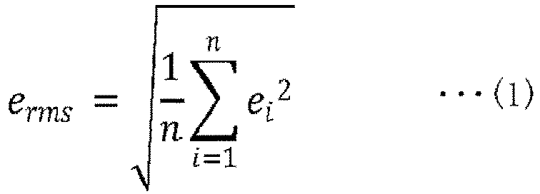
- In the example of expression (1), the
calculation unit 154 calculates the root mean square error as the error value erms, but the error value erms is not limited to this. Thecalculation unit 154 may calculate a mean square error as the error value erms based on expression (2), or may calculate an absolute value average as the error value erms based on expression (3).
[Expression. 2]
[Expression. 3]
- Each time the external parameter stored in the external parameter table 143 is updated, the
calculation unit 154 repeatedly executes the processing of calculating the distance value egap and the error value erms at each time point, and outputs the distance value egap and the error value erms to the specifyingunit 155. - The specifying
unit 155 is a processing unit that specifies the exclusion target point group data based on the distance value egap and the error value erms at each time point. The specifyingunit 155 deletes the specified exclusion target point group data from the detection result table 142. An example of processing of the specifyingunit 155 will be described below. The remaining point group data obtained by removing the exclusion target point group data from the point group data in the detection result table 142 corresponds to a "target point group". - The specifying
unit 155 is a processing unit that specifies the exclusion target point group data based on the distance value egap and the error value erms calculated from the point group data at each time point. - In a case where the distance value egap and the error value erms calculated from the point group data at the time point t = n satisfy the condition R1 and the condition R2, the specifying
unit 155 does not specify the point group data at the time point t = n, as the exclusion target point group data. - In a case where the distance value egap and the error value erms calculated from the point group data at the time point t = n do not satisfy the condition R1 or do not satisfy the condition R2, the specifying
unit 155 specifies the point group data at the time point t = n, as the exclusion target point group data. - The specifying
unit 155 repeatedly executes the above-described processing on the point group data at each time point, to specify the exclusion target point group from the point group data at each time point. The specifyingunit 155 excludes the exclusion target point group data from the detection result table 142. - In a case where the specifying
unit 155 specifies the exclusion target point group data from the point group data at each time point, the specifyingunit 155 notifies the external parameter calculation unit 153 that the exclusion target point group data is included. The specifyingunit 155 repeatedly executes the above-described processing each time the new distance value egap and the new error value erms calculated from the point group data at each time point are acquired from thecalculation unit 154. - Next, the
integration unit 156, thefitting processing unit 157, and theevaluation unit 158 will be described. Theintegration unit 156, thefitting processing unit 157, and theevaluation unit 158 execute processing in a case where the external calibration by theacquisition unit 151, theconversion unit 152, the external parameter calculation unit 153, thecalculation unit 154, and the specifyingunit 155 ends and the subject starts an action. - The
integration unit 156 acquires the point group data corresponding to thesensor 10, from theconversion unit 152. Theintegration unit 156 adjusts the point group data of thesensors 10B to 10C in accordance with the position and orientation of thesensor 10A. For example, theintegration unit 156 aligns the point group data of thesensor 10B with the position and orientation of thesensor 10A by using the external parameter TBA. Theintegration unit 156 aligns the point group data of thesensor 10C with the position and orientation of thesensor 10A by using the external parameter TCA. Theintegration unit 156 aligns the point group data of thesensor 10D with the position and orientation of thesensor 10A by using the external parameter TDA. Theintegration unit 156 acquires each external parameter from the external parameter table 143. - The
integration unit 156 integrates the point group data of thesensor 10A and the point group data of thesensors 10B to 10D, that is aligned with the position and orientation of thesensor 10A, and generates one piece of point group data. Theintegration unit 156 outputs the generated point group data to thefitting processing unit 157. - The
integration unit 156 repeatedly executes the above-described processing each time the point group data of thesensors 10A to 10D is acquired from theconversion unit 152. - The
fitting processing unit 157 is a processing unit that performs fitting for fitting three-dimensional model data of the subject to the point group data. Thefitting processing unit 157 specifies skeleton model data of the subject based on the fitting result. The skeleton model data includes position information of each joint. The fitting processing unit outputs the skeleton model data to theevaluation unit 158. The fitting processing unit repeatedly executes the above-described processing each time the point group data is acquired from theintegration unit 156. - The
evaluation unit 158 is a processing unit that acquires the skeleton model data in time series and evaluates the action of the subject based on the transition of coordinates of each joint of the skeleton model data. For example, theevaluation unit 158 evaluates the action of the subject by using the transition of the coordinates of each joint and a table (not illustrated) in which the type of the action and the success or failure of establishment of the action are defined. Then, theevaluation unit 158 outputs the evaluation result to the display unit 130 and cause the display unit 130 to display the evaluation result. - The evaluation of the action, that is performed by the
evaluation unit 158, is applicable to various scoring competitions. The scoring competitions include, in addition to the gymnastics, a trampoline, a jump in swimming, figure skating, standard moves of karate, ballroom dance, snowboarding, skateboarding, skiing aerial, and surfing. The embodiment may also be applied to a form check or the like for classical ballet, ski-jump, mogul air, turning, baseball, or basketball. The evaluation of the action may also be applied to competitions such as kendo, judo, wrestling, and sumo. The evaluation of the action may also be used to evaluate whether or not the barbell for weight lifting is raised. - Next, an example of a processing procedure in which the
information processing apparatus 100 according to the embodiment performs the external calibration will be described.FIG. 14 is a flowchart illustrating the processing procedure of the processing in which the information processing apparatus according to the embodiment performs external calibration. As illustrated inFIG. 14 , theacquisition unit 151 in theinformation processing apparatus 100 acquires data of the distance image (data of the background image) from thesensor 10 and stores the acquired data of the distance image in the background image table 141 (step S101). - The
acquisition unit 151 acquires data of the distance image (including the background and the target) from thesensor 10 at regular intervals (step S102). Theconversion unit 152 in theinformation processing apparatus 100 generates background difference data based on the data of the background image and the data of the distance image (step S103). Theconversion unit 152 generates point group data at each time point (step S104). - The external parameter calculation unit 153 in the
information processing apparatus 100 calculates the external parameter based on the point group data in the detection result table 142 and registers the external parameter in the external parameter table 143 (step S105). - The
calculation unit 154 in theinformation processing apparatus 100 calculates the distance value egap and the error value erms for the point group data at each time point forming the target (step S106). The specifyingunit 155 in theinformation processing apparatus 100 determines whether or not there is the exclusion target point group data in the point group data forming the target (step S107). - In a case where there is the exclusion target point group data in the point group data forming the target (Yes in step S107), the specifying
unit 155 deletes the exclusion target point group data from the detection result table (step S108), and causes the process to proceed to step S105. - In a case where there is no exclusion target point group data in the point group data forming the target (No in step S107), the
information processing apparatus 100 ends the external calibration. - Next, effects of the
information processing apparatus 100 according to the embodiment will be described. Theinformation processing apparatus 100 updates the external parameters by performing the external calibration with the point group data obtained by excluding the exclusion target point group data from the point group data measured by thesensor 10 at each time point. Theinformation processing apparatus 100 adjusts the position of the point group data by using the updated external parameter, and repeatedly executes the above-described processing until the exclusion target point group data is not detected any more. Thus, it is possible to perform the external calibration by using the point group data obtained by excluding the point group data depending on the sensor individual difference, the sensor characteristics, and the environment, and to improve the accuracy of estimating the positional relationship between the plurality of sensors. -
FIG. 15 is a diagram illustrating an example in which the processing of the information processing apparatus is applied to the point group data at each time point. InFIG. 15 , theinformation processing apparatus 100 executes the processing on each piece ofpoint group data 50a, and thus the pieces of thepoint group data point group data 50b remains. The accuracy of estimating the external parameter is improved by performing the external calibration with thepoint group data 50b. - In a case where the exclusion target point group data is specified, the
information processing apparatus 100 specifies the exclusion target point group data by using both the condition R1 and the condition R2, but the embodiment is not limited to this. Theinformation processing apparatus 100 may calculate only the distance value egap of the point group data at each time point, determine whether or not the distance value egap satisfies the condition R1, and specify the point group data that does not satisfy the condition R1, as the exclusion target point group data. - The
information processing apparatus 100 may calculate only the error value erms of the point group data at each time point, determine whether or not the error value erms satisfies the condition R2, and specify the point group data that does not satisfy the condition R2, as the exclusion target point group data. - Next, an example of a hardware configuration of a computer that implements functions similar to those of the
information processing apparatus 100 described in the above embodiment will be described.FIG. 16 is a diagram illustrating an example of a hardware configuration of a computer that implements functions similar to those of the information processing apparatus. - As illustrated in
FIG. 16 , acomputer 300 includes aCPU 301 that executes various types of arithmetic processing, an input device 302 that receives an input of data from the user, and a display 303. Thecomputer 300 also includes acommunication device 304 that receives the data of the distance image from thesensor 10, and aninterface device 305 coupled to various devices. Thecomputer 300 includes aRAM 306 that temporarily stores various types of information, and ahard disk device 307. Each of devices (theCPU 301 to the hard disk device 307) is coupled to abus 308. - The
hard disk device 307 includes anacquisition program 307a, aconversion program 307b, an externalparameter calculation program 307c, acalculation program 307d, and a specifyingprogram 307e. Thehard disk device 307 includes anintegration program 307f, afitting processing program 307g, and anevaluation program 307h. TheCPU 301 reads theacquisition program 307a, theconversion program 307b, the externalparameter calculation program 307c, thecalculation program 307d, the specifyingprogram 307e, theintegration program 307f, thefitting processing program 307g, and theevaluation program 307h and loads the programs into theRAM 306. - The
acquisition program 307a functions as anacquisition process 306a. Theconversion program 307b functions as aconversion process 306b. The externalparameter calculation program 307c functions as an externalparameter calculation process 306c. Thecalculation program 307d functions as acalculation process 306d. The specifyingprogram 307e functions as a specifyingprocess 306e. Theintegration program 307f functions as anintegration process 306f. Thefitting processing program 307g functions as afitting processing process 306g. Theevaluation program 307h functions as anevaluation process 306h. - Processing of the
acquisition process 306a corresponds to the processing of theacquisition unit 151. Processing of theconversion process 306b corresponds to the processing of theconversion unit 152. Processing of the externalparameter calculation process 306c corresponds to the processing of the external parameter calculation unit 153. Processing of thecalculation process 306d corresponds to the processing of thecalculation units 154. Processing of the specifyingprocess 306e corresponds to the processing of the specifyingunit 155. Processing of theintegration process 306f corresponds to the processing of theintegration unit 156. Processing of thefitting processing process 306g corresponds to the processing of thefitting processing unit 157. Processing of theevaluation process 306h corresponds to the processing of theevaluation unit 158. - The
acquisition program 307a to theevaluation program 307h do not necessarily have to be stored in thehard disk device 307 from the beginning. For example, the programs may be stored in a "portable physical medium" to be inserted into thecomputer 300, such as a flexible disk (FD), a compact disc read-only memory (CD-ROM), a digital versatile disc (DVD), a magneto-optical disc, or an IC card. Thecomputer 300 may read and execute theacquisition program 307a to theevaluation program 307h.
Claims (15)
- A calculation method executed by a computer, the method comprising:acquiring point groups of a target at each time point, that are measured using a plurality of sensors;executing, for each time point, a process of, based on a first point group and a second point group, calculating a first distance value indicating a distance between a center of the first point group and a center of the second point group, and calculating an first error value that indicating a degree of deviation between a surface of a sphere and the first point group and the second point group, the first point group indicating a point group of the target, by which is measured using a first sensor among the plurality of sensors, and the second point group indicating a point group of the target, by which is measured using a second sensor among the plurality of sensors;specifying a first exclusion target point group indicating a point group to be excluded, from the point groups of the target for each time point, based on the first distance value and the first error value calculated for each time point; andcalculating first information indicating a positional relationship between the plurality of sensors by using a first target point group which indicates a point group obtained by excluding the first exclusion target point group from the point groups of the target for each time point.
- The calculation method according to claim 1, further comprising:adjusting a position of the first target point group based on the first information indicating the positional relationship,calculating a second distance value based on the first target point group after the adjusted position, andcalculating a second error value a second error value based on the first target point group after the adjusted position.
- The calculation method according to claim 2, further comprising:
specifying a second exclusion target point group indicating a point group to be excluded, from the point group for each time point, based on the second distance value and the second error value calculated for each time point. - The calculation method according to claim 3, further comprising:
calculating a second information indicating a positional relationship by using a second target point group obtained by excluding the second exclusion target point group, from the first target point group. - The calculation method according to claim 1, further comprising
calculating an initial value of the positional relationship based on the point groups of the target for each time point, wherein
the calculating the first distance value in the process includes calculating the first distance value based on the point groups of the target adjusted based on the initial value for each time point, and
the calculating the first error value included in the process includes calculating the first error value based on the point groups of the target adjusted based on the initial value for each time point. - The calculation method according to claim 1, wherein
the first error value is calculated as any one of a root mean square error, a mean square error, and an absolute value average, of a first distance between the first point group and a surface of a real sphere and/or a second distance between the second point group and the surface of the real sphere. - A calculation program that causes a computer to execute a process, the process comprising:acquiring point groups of a target at each time point, that are measured using a plurality of sensors;executing, for each time point, a process of, based on a first point group and a second point group, calculating a first distance value indicating a distance between a center of the first point group and a center of the second point group, and calculating an first error value that indicating a degree of deviation between a surface of a sphere and the first point group and the second point group, the first point group indicating a point group of the target, by which is measured using a first sensor among the plurality of sensors, and the second point group indicating a point group of the target, by which is measured using a second sensor among the plurality of sensors;specifying a first exclusion target point group indicating a point group to be excluded, from the point groups of the target for each time point, based on the first distance value and the first error value calculated for each time point; andcalculating first information indicating a positional relationship between the plurality of sensors by using a first target point group which indicates a point group obtained by excluding the first exclusion target point group from the point groups of the target for each time point.
- The calculation program according to claim 7, wherein the process further comprising:adjusting a position of the first target point group based on the first information indicating the positional relationship,calculating a second distance value based on the first target point group after the adjusted position, andcalculating a second error value a second error value based on the first target point group after the adjusted position.
- The calculation program according to claim 8, wherein the process further comprising:
specifying a second exclusion target point group indicating a point group to be excluded, from the point group for each time point, based on the second distance value and the second error value calculated for each time point. - The calculation program according to claim 9, wherein the process further comprising:
calculating a second information indicating a positional relationship by using a second target point group obtained by excluding the second exclusion target point group, from the first target point group. - The calculation program according to claim 7, wherein the process further including:calculating an initial value of the positional relationship based on the point groups of the target for each time point, whereinthe calculating the first distance value includes calculating the first distance value based on the point groups of the target adjusted based on the initial value for each time point, andthe calculating the first error value includes calculating the first error value based on the point groups of the target adjusted based on the initial value for each time point.
- The calculation program according to claim 7, wherein
the first error value is calculated as any one of a root mean square error, a mean square error, and an absolute value average, of a first distance between the first point group and a surface of a real sphere and/or a second distance between the second point group and the surface of the real sphere. - An information processing apparatus comprising:an acquiring unit configured to acquire point groups of a target at each time point, that are measured using a plurality of sensors;a calculation unit configured to execute, for each time point, a process of, based on a first point group and a second point group, calculating a first distance value indicating a distance between a center of the first point group and a center of the second point group, and calculating an first error value that indicating a degree of deviation between a surface of a sphere and the first point group and the second point group, the first point group indicating a point group of the target, by which is measured using a first sensor among the plurality of sensors, and the second point group indicating a point group of the target, by which is measured using a second sensor among the plurality of sensors;a specifying unit configured to specify a first exclusion target point group indicating a point group to be excluded, from the point groups of the target for each time point, based on the first distance value and the first error value calculated for each time point; andan external parameter calculation unit configured to calculate first information indicating a positional relationship between the plurality of sensors by using a first target point group which indicates a point group obtained by excluding the first exclusion target point group from the point groups of the target for each time point.
- The information processing apparatus according to claim 13, wherein
the external parameter calculation unit adjusts a position of the first target point group based on the first information indicating the positional relationship,
the calculation unit calculates a second distance value based on the first target point group after the adjusted position, and
the calculation unit calculates a second error value based on the first target point group after the adjusted position. - The information processing apparatus according to claim 14, wherein
the specifying unit specifies a second exclusion target point group indicating a point group to be excluded, from the point group for each time point, based on the second distance value and the second error value calculated for each time point.
Applications Claiming Priority (1)
| Application Number | Priority Date | Filing Date | Title |
|---|---|---|---|
| JP2020100785A JP2021196691A (en) | 2020-06-10 | 2020-06-10 | Calculation method, calculation program and information processor |
Publications (2)
| Publication Number | Publication Date |
|---|---|
| EP3923240A2 true EP3923240A2 (en) | 2021-12-15 |
| EP3923240A3 EP3923240A3 (en) | 2022-03-16 |
Family
ID=75302302
Family Applications (1)
| Application Number | Title | Priority Date | Filing Date |
|---|---|---|---|
| EP21165877.8A Withdrawn EP3923240A3 (en) | 2020-06-10 | 2021-03-30 | Calculation method, calculation program, and information processing apparatus |
Country Status (4)
| Country | Link |
|---|---|
| US (1) | US20210389122A1 (en) |
| EP (1) | EP3923240A3 (en) |
| JP (1) | JP2021196691A (en) |
| CN (1) | CN113781572A (en) |
Citations (1)
| Publication number | Priority date | Publication date | Assignee | Title |
|---|---|---|---|---|
| JP2019086476A (en) | 2017-11-09 | 2019-06-06 | キヤノン株式会社 | Image processing apparatus, image processing method, program and calibration tool |
Family Cites Families (8)
| Publication number | Priority date | Publication date | Assignee | Title |
|---|---|---|---|---|
| JP6164679B2 (en) * | 2012-10-30 | 2017-07-19 | 株式会社Halデザイン研究所 | Camera calibration method and camera calibration apparatus |
| WO2016135985A1 (en) * | 2015-02-27 | 2016-09-01 | 富士通株式会社 | Information providing method, information providing program, information providing device, information processing device, and information providing system |
| JP6480824B2 (en) * | 2015-07-27 | 2019-03-13 | 株式会社日立製作所 | Distance image sensor parameter adjustment method, parameter adjustment apparatus, and elevator system |
| CN107214692B (en) * | 2016-03-22 | 2020-04-03 | 泰科电子(上海)有限公司 | Automatic Calibration Method of Robot System |
| US11397088B2 (en) * | 2016-09-09 | 2022-07-26 | Nanyang Technological University | Simultaneous localization and mapping methods and apparatus |
| JP2018132319A (en) * | 2017-02-13 | 2018-08-23 | キヤノン株式会社 | Information processing apparatus, control method of information processing apparatus, computer program, and memory medium |
| JP7097709B2 (en) * | 2018-02-01 | 2022-07-08 | 株式会社トプコン | Surveying system |
| JP6857161B2 (en) * | 2018-08-27 | 2021-04-14 | 朝日航洋株式会社 | Effective distance acquisition method and laser measurement method |
-
2020
- 2020-06-10 JP JP2020100785A patent/JP2021196691A/en not_active Withdrawn
-
2021
- 2021-03-30 EP EP21165877.8A patent/EP3923240A3/en not_active Withdrawn
- 2021-04-01 US US17/220,184 patent/US20210389122A1/en not_active Abandoned
- 2021-04-13 CN CN202110393902.6A patent/CN113781572A/en active Pending
Patent Citations (1)
| Publication number | Priority date | Publication date | Assignee | Title |
|---|---|---|---|---|
| JP2019086476A (en) | 2017-11-09 | 2019-06-06 | キヤノン株式会社 | Image processing apparatus, image processing method, program and calibration tool |
Non-Patent Citations (1)
| Title |
|---|
| M. RUAN: "Calibration of 3D Sensors Using a Spherical Target", 3DV, 2014 |
Also Published As
| Publication number | Publication date |
|---|---|
| CN113781572A (en) | 2021-12-10 |
| JP2021196691A (en) | 2021-12-27 |
| EP3923240A3 (en) | 2022-03-16 |
| US20210389122A1 (en) | 2021-12-16 |
Similar Documents
| Publication | Publication Date | Title |
|---|---|---|
| CN107080540B (en) | System and method for analyzing gait and postural balance of a person | |
| US10737158B2 (en) | Method and device for recognizing movement of tennis racket | |
| JP6525453B2 (en) | Object position estimation system and program thereof | |
| CN107543530B (en) | Method, system, and non-transitory computer-readable recording medium for measuring rotation of ball | |
| JP6575609B2 (en) | Sensing device and sensing method for moving ball | |
| US20060126941A1 (en) | Face region estimating device, face region estimating method, and face region estimating program | |
| US11074713B2 (en) | Recognition device, recognition system, recognition method, and non-transitory computer readable recording medium | |
| WO2013058427A1 (en) | Apparatus and method for tracking the position of each part of the body for golf swing analysis | |
| Park et al. | Accurate and efficient 3d human pose estimation algorithm using single depth images for pose analysis in golf | |
| CN104850219A (en) | Equipment and method for estimating posture of human body attached with object | |
| KR20210123177A (en) | Device and method to discriminate excersice stance using pressure | |
| KR102468648B1 (en) | Method for calculating heart rate using rPPG signal of serial image and system thereof | |
| US20180028861A1 (en) | Information processing device and information processing method | |
| CN119577516A (en) | Pickleball player motion recognition and analysis system based on multimodal data fusion | |
| JP2023179239A (en) | Information processing program, information processing method, and information processing device | |
| EP3923240A2 (en) | Calculation method, calculation program, and information processing apparatus | |
| WO2020013021A1 (en) | Detecting device, processing device, detecting method, and processing program | |
| KR101844486B1 (en) | Method and Apparatus for Analyzing Ski-Turn | |
| EP4075377A1 (en) | Generation method, generation program, and information processing system | |
| US20220179085A1 (en) | Generation method, non-transitory computer-readable storage medium for storing generation program, and information processing apparatus | |
| CN120419909B (en) | Human body balance evaluation equipment, human body balance evaluation method and device | |
| Panni et al. | Metrological Characterization of a Jump Height Measurement Procedure Based on Inertial Sensors | |
| CN121544127B (en) | An intelligent method and system for managing physical education teaching data. | |
| EP3168780B1 (en) | Image processing apparatus, image processing method, and computer-readable recording medium | |
| JP2018005474A (en) | Mobile entity identification device, mobile entity identification system, mobile entity identification method and program |
Legal Events
| Date | Code | Title | Description |
|---|---|---|---|
| PUAI | Public reference made under article 153(3) epc to a published international application that has entered the european phase |
Free format text: ORIGINAL CODE: 0009012 |
|
| STAA | Information on the status of an ep patent application or granted ep patent |
Free format text: STATUS: THE APPLICATION HAS BEEN PUBLISHED |
|
| AK | Designated contracting states |
Kind code of ref document: A2 Designated state(s): AL AT BE BG CH CY CZ DE DK EE ES FI FR GB GR HR HU IE IS IT LI LT LU LV MC MK MT NL NO PL PT RO RS SE SI SK SM TR |
|
| PUAL | Search report despatched |
Free format text: ORIGINAL CODE: 0009013 |
|
| AK | Designated contracting states |
Kind code of ref document: A3 Designated state(s): AL AT BE BG CH CY CZ DE DK EE ES FI FR GB GR HR HU IE IS IT LI LT LU LV MC MK MT NL NO PL PT RO RS SE SI SK SM TR |
|
| RIC1 | Information provided on ipc code assigned before grant |
Ipc: G06T 7/80 20170101ALI20220207BHEP Ipc: G06T 7/70 20170101ALI20220207BHEP Ipc: G06T 7/66 20170101ALI20220207BHEP Ipc: G06T 7/62 20170101AFI20220207BHEP |
|
| STAA | Information on the status of an ep patent application or granted ep patent |
Free format text: STATUS: REQUEST FOR EXAMINATION WAS MADE |
|
| 17P | Request for examination filed |
Effective date: 20220531 |
|
| RBV | Designated contracting states (corrected) |
Designated state(s): AL AT BE BG CH CY CZ DE DK EE ES FI FR GB GR HR HU IE IS IT LI LT LU LV MC MK MT NL NO PL PT RO RS SE SI SK SM TR |
|
| STAA | Information on the status of an ep patent application or granted ep patent |
Free format text: STATUS: THE APPLICATION HAS BEEN WITHDRAWN |
|
| 18W | Application withdrawn |
Effective date: 20231229 |