EP3923211A1 - Method for decoding colour codes over a quantum erasure channel - Google Patents
Method for decoding colour codes over a quantum erasure channel Download PDFInfo
- Publication number
- EP3923211A1 EP3923211A1 EP20179033.4A EP20179033A EP3923211A1 EP 3923211 A1 EP3923211 A1 EP 3923211A1 EP 20179033 A EP20179033 A EP 20179033A EP 3923211 A1 EP3923211 A1 EP 3923211A1
- Authority
- EP
- European Patent Office
- Prior art keywords
- face
- forest
- tiling
- tree
- erasure
- Prior art date
- Legal status (The legal status is an assumption and is not a legal conclusion. Google has not performed a legal analysis and makes no representation as to the accuracy of the status listed.)
- Granted
Links
Images



Classifications
-
- G—PHYSICS
- G06—COMPUTING OR CALCULATING; COUNTING
- G06N—COMPUTING ARRANGEMENTS BASED ON SPECIFIC COMPUTATIONAL MODELS
- G06N10/00—Quantum computing, i.e. information processing based on quantum-mechanical phenomena
- G06N10/70—Quantum error correction, detection or prevention, e.g. surface codes or magic state distillation
-
- G—PHYSICS
- G06—COMPUTING OR CALCULATING; COUNTING
- G06N—COMPUTING ARRANGEMENTS BASED ON SPECIFIC COMPUTATIONAL MODELS
- G06N10/00—Quantum computing, i.e. information processing based on quantum-mechanical phenomena
- G06N10/20—Models of quantum computing, e.g. quantum circuits or universal quantum computers
-
- G—PHYSICS
- G06—COMPUTING OR CALCULATING; COUNTING
- G06N—COMPUTING ARRANGEMENTS BASED ON SPECIFIC COMPUTATIONAL MODELS
- G06N10/00—Quantum computing, i.e. information processing based on quantum-mechanical phenomena
- G06N10/40—Physical realisations or architectures of quantum processors or components for manipulating qubits, e.g. qubit coupling or qubit control
-
- G—PHYSICS
- G06—COMPUTING OR CALCULATING; COUNTING
- G06N—COMPUTING ARRANGEMENTS BASED ON SPECIFIC COMPUTATIONAL MODELS
- G06N5/00—Computing arrangements using knowledge-based models
- G06N5/01—Dynamic search techniques; Heuristics; Dynamic trees; Branch-and-bound
-
- G—PHYSICS
- G06—COMPUTING OR CALCULATING; COUNTING
- G06N—COMPUTING ARRANGEMENTS BASED ON SPECIFIC COMPUTATIONAL MODELS
- G06N5/00—Computing arrangements using knowledge-based models
- G06N5/04—Inference or reasoning models
- G06N5/046—Forward inferencing; Production systems
- G06N5/047—Pattern matching networks; Rete networks
Definitions
- the present invention concerns the field of quantum computation and more particularly of quantum error correction (QEC). It relates more specifically to a method of decoding colour codes over a quantum erasure channel.
- QEC quantum error correction
- Quantum computers make use of quantum-mechanical phenomena such as superposition and entanglement to perform computation. Through precise control of these phenomena, it is in principle possible for quantum computers to outperform their classical counterparts. Quantum computation is based on the manipulation of quantum bits or "qubits" which can be regarded as a superposition of the 1 and 0 states of a quantum physical variable.
- Quantum computation and quantum information authored by M.A. Nielsen and I.L. Chuang, Cambridge University Press, 2016 .
- the first quantum error correcting codes were independently found by Shor and Steane and a general theory of quantum error correction was subsequently developed.
- An introduction to quantum error correction can be found in the paper of J. Roffe entitled “Quantum Error Correction: an introductory guide” published in Contemporary Physics, vol. 60, no. 3, pp. 226-245, Oct. 2019 .
- the basic principle of quantum error correction coding is to associate the state of each logical qubit with a joint state of a set of underlying physical qubits. From a theoretical point of view, this amounts to expanding the size of a Hilbert space needed for representing a single qubit to a much larger space in which the error on the individual qubits are mapped to a set of mutually orthogonal subspaces.
- a coherent error (for a closed quantum system) affecting a single qubit transforms a superposition state into another superposition state of the Bloch sphere and therefore can be mathematically represented by a unitary operator, E.
- E ⁇ I I + ⁇ X X + ⁇ Z Z + ⁇ Y Y
- ⁇ n
- ⁇ n
- ⁇ n ⁇ are respective basis states of the elementary qubits.
- ECC error control coding
- the codewords satisfy a given set of parity constraints.
- the calculation of a syndrome indicates whether these constraints are met.
- the code space that is the space spanning the codewords is characterised by a null syndrome. Expressed otherwise, the code space and the error space are orthogonal.
- the code space C is a 2 k -dimension subspace of the 2" -dimension Hilbert space, spanned by code vectors which are obtained by entangling n elementary qubits.
- a general state of the code space is also called an encoded state or a logical state. It can be expressed as a superposition of the code vectors.
- the code space can alternatively be described by a stabilizer group, that is, a set of commuting operators forming an Abelian subgroup of the n -fold Pauli group P ⁇ n .
- An element of the stabilizer group is simply referred to as a stabilizer.
- the code space is the intersection of the subspaces fixed by each of the stabilizers, or put differently, the intersection of their eigenspaces with eigenvalue +1. Since stabilizers all commute, it can be verified that the above intersection is not empty, provided that the stabilizer group does not contain - I ⁇ n .
- the stabilizer group can be decomposed into cyclic groups (Kronecker decomposition) the generators of which are stabilizers that can be used for calculating the syndromes of any Pauli error E ⁇ P ⁇ n . They can be regarded as equivalent parity check constraints for classical ECC codes.
- 11 ⁇ can be alternatively described by the stabilizer Z 1 ⁇ Z 2 where Z 1 is a phase-flip operator acting on the first qubit and Z 2 is a phase-flip operator acting on the second qubit.
- Z 1 ⁇ Z 2 leaves unchanged any vector (logical state) belonging to the code space whereas it changes the sign of any errored vector such as X 1 ⁇ I 2
- the code space corresponds to (+1) eigenvalue subspace and the error space corresponds to the (-1) eigenvalue subspace.
- the syndromes calculated with the operators s i ⁇ ⁇ I,Z ⁇ ⁇ n allow to correct the X-type errors (bit-flip errors) and those calculated with the operators s i ⁇ ⁇ I,X ⁇ ⁇ n allow to correct the Z-type error (phase-flip errors).
- the decoding of a CSS code can be split into independent correction of X-type and Z-type errors.
- Topological stabilizer codes are a class of stabilizer codes with geometrically local generators. More specifically, physical qubits can be placed on a manifold, e.g. a torus, so that the code has only stabilizer generators with local support. Topological codes only require local operations for syndrome extraction.
- Colour codes constitute a specific category of topological codes introduced by H. Bombin and M.A. Martin-Delgado in their article entitled “Topological quantum distillation” published in Physical Review Letters, vol. 97, no. 18, oct. 2006, p. 180501 .
- Colour codes in two dimensions are CSS stabilizer codes which are defined on a 2D lattice. Their locality property and bidimensional structure make them good candidates for practical implementations. Furthermore, by construction, colour codes allow to perform logical operations fault-tolerantly.
- the 2D lattice is obtained from a tiling of the 2-torus and meets the following constraints: each vertex represents a qubit and has three incident edges (hence each vertex is 3-valent), the tiling is 3-colourable, three colours being sufficient to label all the faces of the tiling such that no adjacent faces share the same colour.
- Regular three-colourable tilings are generally denoted b.g.r where b,g,r are the respective numbers of edges of the faces of each colour.
- a tiling is called regular if the faces of same color have the same number of edges.
- Three types of lattices are possible for a regular 2D colour code, namely a hexagonal lattice (6.6.6 tiling) as represented in Fig. 1A , a square-hexagon-dodecagon lattice (4.6.12 tiling) as represented in Fig. 1B and a square-octagon lattice (4.8.8 tiling) as represented in Fig. 1C .
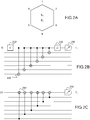
- Fig. 2A shows a face f of the coloured code tiling represented in Fig. 1A .
- stabilizer generator X f is the tensor product of the Pauli X operators on each qubit incident on this face.
- stabilizer generator Z f is the tensor product of the Pauli Z on each qubit incident on this face.
- the code space associated with a face f is defined by the intersection of the +1 eigenspaces of the X f and Z f operators. It is important to note that the whole code space is the intersection of the X f and Z f operators for all the faces of the tiling. However, X f and Z f , only have a local effect, namely on the qubits associated with the vertices of face f , and leave unchanged the other qubits associated with the other vertices of the lattice (in other words, the operator I appears in the tensor product for this qubits).
- the operator X f is used to identify the Z-errors affecting the qubits associated with the vertices of face f .
- the measurement of this operator provides a Z-syndrome bit, z f , which is equal to -1 if the number of Z-errors on the face vertices is odd and equal to +1 if the number of Z-errors on the face vertices is even.
- the operator Z f is used to identify the X-errors affecting the qubits associated with the vertices of face f .
- the measurement of this operator provides a X-syndrome bit, x f , which is equal to -1 if the number of X-errors on the face vertices is odd and equal to +1 if the number of X-errors on the face vertices is even.
- Fig. 2B represents an example of a circuit for calculating a Z-syndrome qubit, capable of identifying a Z-error in the data qubits of Fig. 2A .
- This circuit comprises a plurality of CNOT (controlled-NOT) gates, 220, and a measurement gate, 250.
- the CNOT gates respectively input the 6 qubits of the face represented in Fig. 2A .
- 0 ⁇ is prepared and input to an Hadamard gate, 210, to obtain the state
- + ⁇
- the result is then subjected to an Hadamard transform in 230, and to a measurement in 250.
- This circuit measures operator X f , thereby extracting the Z-syndrome bit, z f , of the qubits associated with the face vertices.
- Fig. 2C represents an example of a circuit for calculating an X-syndrome qubit, capable of identifying a X-error in the data qubits of Fig. 2A .
- This circuit comprises a plurality of CNOT (controlled-NOT) gates, 240, in series, (orientated in the direction opposite to the CNOT gates 220) and respectively controlled by the 6 qubits of the face, the first CNOT gate inputting a prepared ancilla qubit
- CNOT controlled-NOT
- This circuit measures operator Z f , thereby extracting the X-syndrome bit of the qubits associates with the face vertices.
- Decoding means determining the most probable error E affecting the set of qubits from the extracted syndromes and recovering the most likely set of qubits.
- An object of the present invention is therefore to propose a method for decoding colour codes which is simpler and more efficient than those known from the prior art.
- the present invention enables to find an almost maximum-likelihood decoding solution in linear time or a maximum-likelihood decoding solution in almost linear time.
- the measurement of X f over the qubits incident on f (that is associated with the vertices of f ) provides a Z-syndrome bit z f indicating the parity of the number of Z-type Pauli errors, namely the number of phase flips affecting these qubits.
- the measurement of Z f over the qubits incident on f (that is associated with the vertices of f ) provides a X-syndrome bit, x f indicating the parity of the number of X type Pauli errors, namely the number of bit flips affecting these qubits.
- the present invention concerns the decoding of a colour code over a quantum erasure channel (QEC), that is the correction of erased qubits.
- Erasures are defined as arbitrary errors at known locations in the lattice. More specifically, a qubit is considered as erased if it is affected by a random Pauli error belonging to the set of operators ⁇ I,X,Z,XZ ⁇ , each operator having the same probability (25%).
- Operator I corresponds to the case of a non-erroneous qubit
- operator X to the case of a bit-flip
- operator Z to the case of a phase flip
- operator XZ to the combination of phase-flip and bit-flip.
- the present invention can be used in particular as a subroutine for error decoding more general Pauli error models, similarly to the Union-Find decoder mentioned above.
- Fig. 3 represents a flow chart of a colour code decoding method according to an embodiment of the present invention.
- the decoding method inputs the set ⁇ of the erased physical qubits at step 300.
- These erased qubits can be identified for example as labels of vertices in the lattice where the erasures have occurred.
- a spanning forest, F spanning all the erased qubits of ⁇ is then determined in 310.
- a tree spanning an undirected connected graph G is a tree which includes all of the vertices of G , with the minimum possible number of edges.
- a graph may have several spanning trees. If the graph G has several connected components which are disconnected with each other, it can be spanned by a spanning forest, that is a set of spanning trees, each tree spanning a connected component of said graph.
- the set of vertices of ⁇ defines a graph G , two vertices of ⁇ sharing the same edge of a face in the tiling being linked by an edge of graph G .
- This graph is in general disconnected as cluster of erasures may be spaced apart in the lattice. However, each connected component of this graph may be spanned by a spanning tree thereby leading to a spanning forest.
- the spanning forest F can be obtained by conventionally running a depth-first search (DFS) algorithm or a breadth-first search (BFS) algorithm on graph G .
- DFS depth-first search
- BFS breadth-first search
- the syndrome for each face f of the code tiling is calculated. More specifically, a first syndrome bit is calculated by measuring the stabilizer operator X f on the qubits incident on this face, with the help of a first ancilla bit, and a second syndrome bit is calculated by measuring the stabilizer Z f operator on the same qubits, with the help of a second ancilla bit.
- the number of phase flips (resp. bit flips) affecting the qubits incident on face is even (which is in particular the case when all the qubits in question are not erroneous).
- the first (resp. second) syndrome bit is non null, that is has a value -1, the number of phase flips (resp. bit flips) affecting these qubits is odd.
- the spanning forest F is divided into trees, each tree T spanning a connected component of F , more precisely a connected component of the graph G generated by ⁇ .
- the faces of the tiling which are touched by at least a vertex of a tree T of F are identified.
- touched by a vertex we mean here that the vertex is an endpoint of an edge of the face in question.
- Fig. 7 Such a situation is illustrated in Fig. 7 .
- the 6.6.6 colour code tiling has been represented uncoloured and the vertices with filled dots indicate the elements of ⁇ , that is the erased qubits.
- the spanning forest F is composed here of two trees T 1 ,T 2 , no face of the tiling being touched by both T 1 and T 2 .
- Fig. 8 The spanning forest is composed here of four trees T 1 1 ,T 2 1 ,T 1 2 ,T 2 2 . Indeed, it can be noticed that face f 1 is touched by trees T 1 1 and T 2 1 and faces f 2 , f 3 are touched by trees T 1 2 and T 2 2 .
- Fig. 4 represents the flowchart of a colour code decoding method according a trimming process.
- This decoding method iterates over the trees, branches and leaves of the spanning forest F previously obtained.
- the pendant face of the current leaf is determined at step 440.
- pendant face of a leaf V i we mean the face of the tiling for which the boundary comprises vertex V i but not vertex V i +1 of branch B. If the branch B contains only one vertex (which may happen for isolated errors, or after trimming all the other vertices from the tree), any face of the tiling whose boundary comprises that vertex may be used as pendant face.
- step 450 it is checked whether another vertex of forest F belongs to the pendant face. Importantly, in the affirmative, the qubit associated with vertex V i is left unchanged, that is no error correction operation is made on V i . Although performing no error correction operation on V i may appear as paradoxical, it can be shown that this does not affect the decoding process, due to the trimmable property of the erasure set.
- the leaf is then trimmed at step 470 and it is proceeded to the next node of the branch, thus becoming a leaf.
- ⁇ i ⁇ associated with vertex V i is corrected at step 460 by applying a correcting operator:
- ( x f ,z f ) is the syndrome calculated for face f at step 320, x f being the X-syndrome bit and z f being the Z-syndrome bit.
- the leaf is then trimmed at step 470 and it is proceeded to the next node of the branch, thus becoming a leaf.
- the complete decoding of the erased qubits is linear time that is the time required for the complete decoding depends linearly with the number n of the physical qubits.
- Fig. 5 represents a flowchart of a colour code decoding method according to a first variant of the present invention.
- this decoding method is performed when at least one face of the tiling is touched by more than one tree of the spanning forest F .
- the decoding method starts again with the spanning forest F at step 510.
- the faces being touched by at least two trees of the forest are identified at step 520.
- these faces are f 1 , f 2 , f 3 in Fig. 8 .
- pseudo-erasures are inserted at some of their vertices so that the trees touching the face are connected. Note that in some instances, it may be necessary to insert a plurality (two in case of a hexagonal lattice) consecutive erasures if two trees touch the face at opposite vertices.
- the decoding can be performed in linear time.
- Fig. 6 represents a flowchart of a colour code decoding method according to a second variant of the present invention.
- This decoding method is an alternative to the first variant set out above, it starts again with the spanning forest F at step 610 and then enters an iterative loop over the trees, branches and leaves as in Fig. 4 , steps 620 to 650 being identical to steps 410 to 450.
- Steps 670 to 695 are respectively identical to steps 470 to 495.
- a linear system linking the variables of the inactivated erasures with the syndrome bits of the faces comprising these erasures is solved at step 697.
- the solution of the linear system can conventionally be obtained by Gaussian elimination.
- the complexity of the decoding method is no more linear with time because solving the linear system dominates. Resolution of the linear system scales as the cube of the number of inactivated erasures but, since the number of inactivated erasures is very small with respect to the total number of erasures, the decoding method can be regarded as almost linear in time with respect to the number of qubits.
- N the set of operators
- P ⁇ P n the set of operators
- Fig. 10A represents the logical X-error rate vs. the erasure probability for a colour code based on a 6.6.6 tiling when using the first variant of the present invention (pseudo-erasures insertion-based decoding). A similar figure would be obtained for the logical Z-error rate.
- the erasure correcting capability of a quantum error correcting code of distance d t + 1 amounts to t erasures.
- the error correction threshold is about 0.43. In other words, if the erasure probability lies below 0.43 it is possible to efficiently perform error correction, assuming the size of the code is large enough.
- Fig. 10B represents the X-error rate vs. the erasure probability for a colour code based on a 6.6.6 tiling when using the second variant of the present invention (inactivation-based decoding).
- the error correction threshold is about 0.5, higher than for the first variant, and that, for a given distance the logical error rate is lower than in the first variant.
- the second variant performs better than the first, although at the expense of a higher complexity.
Landscapes
- Engineering & Computer Science (AREA)
- Theoretical Computer Science (AREA)
- General Physics & Mathematics (AREA)
- Physics & Mathematics (AREA)
- Evolutionary Computation (AREA)
- Artificial Intelligence (AREA)
- Computing Systems (AREA)
- General Engineering & Computer Science (AREA)
- Data Mining & Analysis (AREA)
- Mathematical Physics (AREA)
- Software Systems (AREA)
- Mathematical Analysis (AREA)
- Computational Mathematics (AREA)
- Condensed Matter Physics & Semiconductors (AREA)
- Mathematical Optimization (AREA)
- Pure & Applied Mathematics (AREA)
- Computational Linguistics (AREA)
- Computer Vision & Pattern Recognition (AREA)
- Error Detection And Correction (AREA)
Abstract
Description
- The present invention concerns the field of quantum computation and more particularly of quantum error correction (QEC). It relates more specifically to a method of decoding colour codes over a quantum erasure channel.
- Quantum computers make use of quantum-mechanical phenomena such as superposition and entanglement to perform computation. Through precise control of these phenomena, it is in principle possible for quantum computers to outperform their classical counterparts. Quantum computation is based on the manipulation of quantum bits or "qubits" which can be regarded as a superposition of the 1 and 0 states of a quantum physical variable.
- A general introduction to quantum computation can be found in the reference book entitled "Quantum computation and quantum information" authored by M.A. Nielsen and I.L. Chuang, Cambridge University Press, 2016.
- Although various technologies exist for implementing quantum computers, they all share the same shortcomings, namely that the qubits are affected by external noise and decoherence. Whereas bits in classical computers are materialized at the physical level by on/off states of transistor switches with high error margins, there is no such security for qubits. Indeed, the fragile superposition of states of a qubit may easily be disturbed by its environment and collapse, resulting in a loss of information. Quantum computers therefore fundamentally require error correction at the physical level.
- Simple transposition of classical error correction schemes cannot be envisaged though, since qubits are subject to the no-cloning theorem i.e. quantum information cannot be duplicated in the same way as classical information. Furthermore, any measurement of a qubit causes a collapse to either state |0〉 or |1〉, thereby preventing restoration of the original information.
- The first quantum error correcting codes were independently found by Shor and Steane and a general theory of quantum error correction was subsequently developed. An introduction to quantum error correction can be found in the paper of J. Roffe entitled "Quantum Error Correction: an introductory guide" published in Contemporary Physics, vol. 60, no. 3, pp. 226-245, Oct. 2019.
- The basic principle of quantum error correction coding is to associate the state of each logical qubit with a joint state of a set of underlying physical qubits. From a theoretical point of view, this amounts to expanding the size of a Hilbert space needed for representing a single qubit to a much larger space in which the error on the individual qubits are mapped to a set of mutually orthogonal subspaces.
- More specifically, let us consider first a single qubit. It can generally be expressed as a superposition of basis states |0〉 and |1〉:


- A coherent error (for a closed quantum system) affecting a single qubit transforms a superposition state into another superposition state of the Bloch sphere and therefore can be mathematically represented by a unitary operator, E. Such an operator can be decomposed in the Pauli basis of two-dimensional matrices of complex values:


- From expression (3) and (4-4), it can be understood that, if an error correcting code is able to correct an error of the X-type (i.e. a bit-flip) or of the Z-type (i.e. a phase-flip), it can correct any coherent error. This decomposition property is also called discretization of quantum error.
- We can therefore restrict ourselves to errors represented by operators X p Z q where p = 0,1 and q = 0,1.
- Furthermore, the Pauli matrices operating on a single qubit define a group, denoted P 1 = {±I, ±i I , ±X, ±i X , ±Y, ±i Y, ±Z, ±i Z}.
- Considering now a multi qubit system, that is a quantum system (or register) of n qubits, a basis state |ψ〉 n of this system can be represented by the tensor product:

- Similarly, an error affecting a multi qubit system state can be expressed as a tensor product of operators:

- By the same token, the correction of errors in the multi qubit system can be restricted to those belonging to the n-fold Pauli group P ⊗n = P 1 ⊗....⊗ P 1, namely by the tensor product operators:

values 0 or 1. - In classical error control coding (ECC), the codewords satisfy a given set of parity constraints. The calculation of a syndrome indicates whether these constraints are met. The code space, that is the space spanning the codewords is characterised by a null syndrome. Expressed otherwise, the code space and the error space are orthogonal.
- Transposed to a multi qubit system of size n, the code space C is a 2 k -dimension subspace of the 2" -dimension Hilbert space, spanned by code vectors which are obtained by entangling n elementary qubits. A general state of the code space is also called an encoded state or a logical state. It can be expressed as a superposition of the code vectors.
- The code space can alternatively be described by a stabilizer group, that is, a set of commuting operators forming an Abelian subgroup of the n-fold Pauli group P⊗n . An element of the stabilizer group is simply referred to as a stabilizer. The code space is the intersection of the subspaces fixed by each of the stabilizers, or put differently, the intersection of their eigenspaces with eigenvalue +1. Since stabilizers all commute, it can be verified that the above intersection is not empty, provided that the stabilizer group does not contain - I ⊗n .
- The stabilizer group can be decomposed into cyclic groups (Kronecker decomposition) the generators of which are stabilizers that can be used for calculating the syndromes of any Pauli error E ∈ P ⊗n . They can be regarded as equivalent parity check constraints for classical ECC codes.
- If we denote the set of generators by S = {s 1,s 2,...,s m} ⊂ P ⊗n such that [s i ,s j ] = 0 and, the stabilizer code associated with S is defined by:

- An error E translates into the syndromes [E,s i ] ∈ {-1,+}, i = 1,...n from which a correction operator can be deduced (error decoding).
- Taking the example of a 2-qubit system, the code space spanned by |00〉 and |11〉 can be alternatively described by the stabilizer Z 1 ⊗ Z2 where Z 1 is a phase-flip operator acting on the first qubit and Z 2 is a phase-flip operator acting on the second qubit. Z 1 ⊗ Z 2 leaves unchanged any vector (logical state) belonging to the code space whereas it changes the sign of any errored vector such as X 1 ⊗ I 2|Ψ〉 n or I 1 ⊗ X2|Ψ〉 n . In other words, the code space corresponds to (+1) eigenvalue subspace and the error space corresponds to the (-1) eigenvalue subspace.
- CSS codes (named after their inventors R. Calderbank, P. Shor and A. Steane) are a family of stabilizer codes defined by the subgroup of P ⊗n :

- The syndromes calculated with the operators s i ∈ {I,Z}⊗n allow to correct the X-type errors (bit-flip errors) and those calculated with the operators s i ∈ {I,X}⊗n allow to correct the Z-type error (phase-flip errors). Hence, the decoding of a CSS code can be split into independent correction of X-type and Z-type errors.
- Topological stabilizer codes are a class of stabilizer codes with geometrically local generators. More specifically, physical qubits can be placed on a manifold, e.g. a torus, so that the code has only stabilizer generators with local support. Topological codes only require local operations for syndrome extraction.
- Colour codes constitute a specific category of topological codes introduced by H. Bombin and M.A. Martin-Delgado in their article entitled "Topological quantum distillation" published in Physical Review Letters, vol. 97, no. 18, oct. 2006, p. 180501.
- Colour codes in two dimensions are CSS stabilizer codes which are defined on a 2D lattice. Their locality property and bidimensional structure make them good candidates for practical implementations. Furthermore, by construction, colour codes allow to perform logical operations fault-tolerantly.
- The 2D lattice is obtained from a tiling of the 2-torus and meets the following constraints: each vertex represents a qubit and has three incident edges (hence each vertex is 3-valent), the tiling is 3-colourable, three colours being sufficient to label all the faces of the tiling such that no adjacent faces share the same colour.
- Regular three-colourable tilings are generally denoted b.g.r where b,g,r are the respective numbers of edges of the faces of each colour. A tiling is called regular if the faces of same color have the same number of edges. Three types of lattices are possible for a regular 2D colour code, namely a hexagonal lattice (6.6.6 tiling) as represented in
Fig. 1A , a square-hexagon-dodecagon lattice (4.6.12 tiling) as represented inFig. 1B and a square-octagon lattice (4.8.8 tiling) as represented inFig. 1C . -
Fig. 2A shows a face f of the coloured code tiling represented inFig. 1A . - Each face f is associated with two stabilizer generators, X f ,Z f defined by:


- More generally, for a given face f of a colour code tiling, stabilizer generator X f is the tensor product of the Pauli X operators on each qubit incident on this face.
- Similarly, for a given face f, stabilizer generator Z f is the tensor product of the Pauli Z on each qubit incident on this face.
- The code space associated with a face f is defined by the intersection of the +1 eigenspaces of the X f and Z f operators. It is important to note that the whole code space is the intersection of the X f and Z f operators for all the faces of the tiling. However, X f and Z f , only have a local effect, namely on the qubits associated with the vertices of face f, and leave unchanged the other qubits associated with the other vertices of the lattice (in other words, the operator I appears in the tensor product for this qubits).
- The operator X f is used to identify the Z-errors affecting the qubits associated with the vertices of face f. The measurement of this operator provides a Z-syndrome bit, zf , which is equal to -1 if the number of Z-errors on the face vertices is odd and equal to +1 if the number of Z-errors on the face vertices is even.
- Similarly, the operator Z f is used to identify the X-errors affecting the qubits associated with the vertices of face f. The measurement of this operator provides a X-syndrome bit, xf , which is equal to -1 if the number of X-errors on the face vertices is odd and equal to +1 if the number of X-errors on the face vertices is even.
-
Fig. 2B represents an example of a circuit for calculating a Z-syndrome qubit, capable of identifying a Z-error in the data qubits ofFig. 2A . - This circuit comprises a plurality of CNOT (controlled-NOT) gates, 220, and a measurement gate, 250. The CNOT gates respectively input the 6 qubits of the face represented in
Fig. 2A . - First an ancilla qubit |0〉 is prepared and input to an Hadamard gate, 210, to obtain the state

CNOT gates 220 for creating Bell states. The result is then subjected to an Hadamard transform in 230, and to a measurement in 250. This circuit measures operator X f , thereby extracting the Z-syndrome bit, zf , of the qubits associated with the face vertices. -
Fig. 2C represents an example of a circuit for calculating an X-syndrome qubit, capable of identifying a X-error in the data qubits ofFig. 2A . - This circuit comprises a plurality of CNOT (controlled-NOT) gates, 240, in series, (orientated in the direction opposite to the CNOT gates 220) and respectively controlled by the 6 qubits of the face, the first CNOT gate inputting a prepared ancilla qubit |0〉.
- The result is then input to
measurement gate 250. This circuit measures operator Z f , thereby extracting the X-syndrome bit of the qubits associates with the face vertices. - Different techniques have been proposed for decoding colour codes. Decoding means determining the most probable error E affecting the set of qubits from the extracted syndromes and recovering the most likely set of qubits.
- In particular, it is known from the paper of Kubica et al. entitled "Efficient colour code decoders in d ≥ 2 dimensions from toric code decoders" published in 2019 as arXiv: 1905.07393 to project a colour code onto surface codes. The thus obtained surface codes can be then decoded according to a so-called Minimum-Weight Perfect Matching (MWPM) algorithm, the complexity of which is however not linear with the number of physical qubits. More recently, a so-called Union-Find decoder using a peeling algorithm for correcting erasures over the quantum erasure channel, has shown its capability to be run (in the worst case) in almost linear time with respect to the number of physical qubits. A presentation of the Union-Find decoder can be found in the paper of N. Delfosse et al. entitled "Almost-linear decoding algorithm for topological codes" published in Sept. 2017 as arXiv:1709.06218.
- However, using a Union-Find decoder for decoding a colour code still requires a prior projection on surface codes, decoding the obtained surface codes, and lifting back the error estimates to the original colour code, which is quite a complex process.
- An object of the present invention is therefore to propose a method for decoding colour codes which is simpler and more efficient than those known from the prior art. In particular, the present invention enables to find an almost maximum-likelihood decoding solution in linear time or a maximum-likelihood decoding solution in almost linear time.
- The present invention is defined by the appended independent claim. Various preferred embodiments are defined in the dependent claims.
- The present invention will be better understood from the description of the following embodiments, by way of illustration and in no way limitative thereto:
-
Fig. 1A , already described, schematically represents a 6.6.6 tiling defining a first type of colour code known from the prior art; -
Fig. 1B , already described, schematically represents a 4.6.12 tiling defining a second type of colour code known from the prior art; -
Fig. 1C , already described, schematically represents a 4.8.8 tiling defining a third type of colour code known from the prior art; -
Fig. 2A , already described, schematically represents a face of the tiling ofFig. 1A with six data qubits and two stabilizer generators; -
Fig. 2B , already described, schematically represents an example of a circuit for calculating a first syndrome qubit, capable of identifying a Z-error in the data qubits ofFig. 2A ; -
Fig. 2C , already described, schematically represents an example of a circuit for calculating a second syndrome qubit, capable of identifying an X-error in the data qubits ofFig. 2A ; -
Fig. 3 represents a flow chart of a colour code decoding method according to an embodiment of the present invention; -
Fig. 4 represents a flow chart of a colour code decoding method according to the trimming process mentioned inFig. 3 ; -
Fig. 5 represents a flow chart of a colour code decoding method according to a first variant of the present invention; -
Fig. 6 represents a flow chart of a colour code decoding method according to a second variant of the present invention; -
Fig. 7 schematically represents the tiling of a colour code with a forest spanning a first set of erasures over a quantum erasure channel; -
Figs. 8 schematically represents the tiling of a colour code with a forest spanning a second set of erasures over a quantum erasure channel; -
Fig. 9 schematically represents the tiling ofFig. 8 with an extended spanning forest; -
Fig. 10A represents the logical X-error rate vs. the erasure probability for a colour code based on a 6.6.6 tiling when using the first variant of the present invention; -
Fig. 10B represents the logical X-error rate vs. the erasure probability for a colour code based on a 6.6.6 tiling when using the second variant of the present invention. - We will consider in the following a 2D colour code as set out in the introduction. Without loss of generality and for the sake of simplicity, we will also assume that the colour code is based on a hexagonal lattice, that is a 6.6.6 three coloured tiling. In particular, the man skilled in the art will understand that the present equally applies to a 4.8.8 or 4.6.12 tiling as mentioned above or more generally to any other regular, or possibly irregular, 3-colourable tiling.
- We recall that the physical qubits of the code are associated with the vertices of the lattice and that each face f of the tiling is associated with a X-type stabiliser, X f , and a Z-type stabiliser, Z f , advantageously defined by expressions (10-1) and (10-2).
- The measurement of X f over the qubits incident on f (that is associated with the vertices of f) provides a Z-syndrome bit z f indicating the parity of the number of Z-type Pauli errors, namely the number of phase flips affecting these qubits.
- The measurement of Z f over the qubits incident on f (that is associated with the vertices of f) provides a X-syndrome bit, xf indicating the parity of the number of X type Pauli errors, namely the number of bit flips affecting these qubits.
- The present invention concerns the decoding of a colour code over a quantum erasure channel (QEC), that is the correction of erased qubits. Erasures are defined as arbitrary errors at known locations in the lattice. More specifically, a qubit is considered as erased if it is affected by a random Pauli error belonging to the set of operators {I,X,Z,XZ}, each operator having the same probability (25%). Operator I corresponds to the case of a non-erroneous qubit, operator X to the case of a bit-flip, operator Z to the case of a phase flip and operator XZ to the combination of phase-flip and bit-flip.
- The present invention can be used in particular as a subroutine for error decoding more general Pauli error models, similarly to the Union-Find decoder mentioned above.
-
Fig. 3 represents a flow chart of a colour code decoding method according to an embodiment of the present invention. - The decoding method inputs the set Ω of the erased physical qubits at
step 300. These erased qubits can be identified for example as labels of vertices in the lattice where the erasures have occurred. - A spanning forest, F, spanning all the erased qubits of Ω is then determined in 310.
- We recall that, in graph theory, a tree spanning an undirected connected graph G is a tree which includes all of the vertices of G, with the minimum possible number of edges. In general, a graph may have several spanning trees. If the graph G has several connected components which are disconnected with each other, it can be spanned by a spanning forest, that is a set of spanning trees, each tree spanning a connected component of said graph.
- The set of vertices of Ω defines a graph G, two vertices of Ω sharing the same edge of a face in the tiling being linked by an edge of graph G. This graph is in general disconnected as cluster of erasures may be spaced apart in the lattice. However, each connected component of this graph may be spanned by a spanning tree thereby leading to a spanning forest.
- The spanning forest F can be obtained by conventionally running a depth-first search (DFS) algorithm or a breadth-first search (BFS) algorithm on graph G.
- At
step 320, the syndrome for each face f of the code tiling is calculated. More specifically, a first syndrome bit is calculated by measuring the stabilizer operator X f on the qubits incident on this face, with the help of a first ancilla bit, and a second syndrome bit is calculated by measuring the stabilizer Z f operator on the same qubits, with the help of a second ancilla bit. - If the first (resp. second) syndrome bit is null, that is has a value +1, the number of phase flips (resp. bit flips) affecting the qubits incident on face is even (which is in particular the case when all the qubits in question are not erroneous). Conversely, if the first (resp. second) syndrome bit is non null, that is has a value -1, the number of phase flips (resp. bit flips) affecting these qubits is odd.
- It is worth noting that the order of
steps - At
step 330, the spanning forest F is divided into trees, each tree T spanning a connected component of F, more precisely a connected component of the graph G generated by Ω. - At
step 340, the faces of the tiling which are touched by at least a vertex of a tree T of F are identified. By touched by a vertex we mean here that the vertex is an endpoint of an edge of the face in question. - If there exists at least one face in the tiling that is touched by more than one tree as checked at
step 350, then the set Ω is qualified as non-trimmable and the decoding process goes on with 355. Two different algorithms can be used in 355 which are respectively described further below in relation withFigs. 5 and6 . - Conversely, if no face of the tiling is touched by more than one tree of F, the set Ω is qualified as trimmable and the decoding proceeds further with 360 as described further below in relation with
Fig. 4 . - Such a situation is illustrated in
Fig. 7 . The 6.6.6 colour code tiling has been represented uncoloured and the vertices with filled dots indicate the elements of Ω, that is the erased qubits. The faces labelled "-1" are those for which the syndrome is not null, that is one syndrome bit or both is/are not null, i.e. xf = -1 and/or z f = -1. The non-labelled faces are those for which the syndrome is null, i.e. xf = +1 and zf = +1. The spanning forest F is composed here of two trees T 1 ,T 2 , no face of the tiling being touched by both T 1 and T 2. - By contrast, the situation of a non-trimmable forest has been represented in
Fig. 8 . The spanning forest is composed here of four trees T 1 1 ,T 2 1 ,T 1 2 ,T 2 2 . Indeed, it can be noticed that face f 1 is touched by trees T 1 1 and T 2 1 and faces f2, f 3 are touched by trees T 1 2 and T 2 2. -
Fig. 4 represents the flowchart of a colour code decoding method according a trimming process. - This decoding method iterates over the trees, branches and leaves of the spanning forest F previously obtained.
- More specifically, after inputting the spanning forest F at step 410, an iterative loop is entered.
- At step 420 a tree T of forest F is selected, then at step 430 a branch of the tree and finally the leaf Vi of the current branch B = (V 1 ,V 2,..,Vk ) where k is the number of nodes of the branch.
- For each leaf of the current branch starting from vertex V 1 and progressively trimming the branch from V 1 to V k-1, the pendant face of the current leaf is determined at
step 440. By pendant face of a leaf Vi , we mean the face of the tiling for which the boundary comprises vertex Vi but not vertex V i+1 of branch B. If the branch B contains only one vertex (which may happen for isolated errors, or after trimming all the other vertices from the tree), any face of the tiling whose boundary comprises that vertex may be used as pendant face. - At
step 450, it is checked whether another vertex of forest F belongs to the pendant face. Importantly, in the affirmative, the qubit associated with vertex Vi is left unchanged, that is no error correction operation is made on Vi . Although performing no error correction operation on Vi may appear as paradoxical, it can be shown that this does not affect the decoding process, due to the trimmable property of the erasure set. - The leaf is then trimmed at
step 470 and it is proceeded to the next node of the branch, thus becoming a leaf. - Conversely, if the boundary of the pendant face does not contain any other vertex of forest F, the qubit |ϕi 〉 associated with vertex Vi is corrected at
step 460 by applying a correcting operator:
step 320, xf being the X-syndrome bit and z f being the Z-syndrome bit. The leaf is then trimmed atstep 470 and it is proceeded to the next node of the branch, thus becoming a leaf. - At
step 475, it is checked whether the root of the branch has been reached, that is if i = k. If it is not the case, the decoding method proceeds with the next leaf atstep 440. Conversely, if the root of the branch has been reached, it is checked atstep 480 whether the last branch of tree T has been trimmed. If it is not the case, the decoding method proceeds with the next branch atstep 485 and jump back tostep 430. - Conversely, if all the branches of tree T have been trimmed, it is checked whether last tree of the spanning forest F has been processed. In the negative, the method proceeds with the next tree at
step 495 and jumps back tostep 420. Conversely, in the affirmative, the whole spanning forest has been processed and the decoding stop atstep 497. - The man skilled in the art will understand that, in the present instance, the complete decoding of the erased qubits is linear time that is the time required for the complete decoding depends linearly with the number n of the physical qubits.
-
Fig. 5 represents a flowchart of a colour code decoding method according to a first variant of the present invention. - It is recalled that this decoding method is performed when at least one face of the tiling is touched by more than one tree of the spanning forest F.
- The decoding method starts again with the spanning forest F at
step 510. - First, the faces being touched by at least two trees of the forest are identified at
step 520. For example, these faces are f 1 , f 2 , f 3 inFig. 8 . - For each such a face, at
step 530, pseudo-erasures are inserted at some of their vertices so that the trees touching the face are connected. Note that in some instances, it may be necessary to insert a plurality (two in case of a hexagonal lattice) consecutive erasures if two trees touch the face at opposite vertices. - For example, if we consider the spanning forest illustrated in
Fig. 8 , a pseudo-erasure can be inserted at vertex V 1 to connect trees T 1 1 and T 2 1 thereby forming a new tree of erasures, T 1 = T 1 1 ∪T 2 1 ∪V 1. Similarly, a pseudo-erasure can be inserted at vertex V 2 to connect trees T 1 2 and T 2 2 thereby forming a new tree of erasures, T2 = T 1 2 ∪T 2 2 ∪V 2. Note that insertion of further pseudo-erasures is not necessary, the two trees touching face f 3 being already connected. The forest thus obtained contains less trees and is denoted F'. - The insertion of pseudo-erasures brings us back to a trimmable forest configuration and the decoding method illustrated in
Fig. 4 can be applied atstep 550 on forest F'. - As in the original trimmable configuration, the decoding can be performed in linear time.
-
Fig. 6 represents a flowchart of a colour code decoding method according to a second variant of the present invention. - This decoding method is an alternative to the first variant set out above, it starts again with the spanning forest F at
step 610 and then enters an iterative loop over the trees, branches and leaves as inFig. 4 ,steps 620 to 650 being identical to steps 410 to 450. - However, after the pendant face f has been determined for current leaf Vi at
step 640, we consider two cases according to whether or not another vertex of forest F belongs to the face in question. - If another vertex of forest F belongs to face f, we again consider two cases, according to whether all the vertices in F ∩ f belong to the same spanning tree or not as checked in 655. If all the vertices in F ∩ f belong to the same spanning tree, which is thus necessarily the spanning tree containing Vi , the qubit associated with vertex Vi is left unchanged (no error correction operation is made in Vi ). If the vertices in F ∩ f belong to more than one spanning tree, the vertex Vi is inactivated in 665. By inactivation of an erasure, it is meant that the binary values p,q of the four possible errors X p Z q affecting the erased qubit are considered as variables, and propagated through subsequent decoding steps.
- If there is no other vertex of F belonging to face f, as checked in 650, the qubit associated with vertex Vi is corrected according to (11).
- Steps 670 to 695 are respectively identical to
steps 470 to 495. - However, after the forest has been completely parsed, a linear system linking the variables of the inactivated erasures with the syndrome bits of the faces comprising these erasures is solved at
step 697. The solution of the linear system can conventionally be obtained by Gaussian elimination. - After having obtained the p,q values of the various inactivated erasures, the corresponding errors are corrected. More specifically, if we denote |ϕi 〉 the state of the erased qubit, the qubit is recovered by applying thereto operator X p Z q :

- The complexity of the decoding method is no more linear with time because solving the linear system dominates. Resolution of the linear system scales as the cube of the number of inactivated erasures but, since the number of inactivated erasures is very small with respect to the total number of erasures, the decoding method can be regarded as almost linear in time with respect to the number of qubits.
- Whatever the variant used, it is important to note that the error decoding method provides a correction up to any element of the normalizer group of S in Pn , denoted N, that is the set of operators P ∈ Pn such that P.S = S.P. Note that errors in N cannot be detected, as they commute with all the stabilizers, thus all the syndrome bits are null (equal to +1), in a same way as an error transforming a codeword into another codeword of a conventional ECC cannot be detected.
-
Fig. 10A represents the logical X-error rate vs. the erasure probability for a colour code based on a 6.6.6 tiling when using the first variant of the present invention (pseudo-erasures insertion-based decoding). A similar figure would be obtained for the logical Z-error rate. - The curves of erasure probability are given for various minimum distances. It is recalled that the distance of a stabilizer code is defined by:

- It can be seen from the figure that the error correction threshold is about 0.43. In other words, if the erasure probability lies below 0.43 it is possible to efficiently perform error correction, assuming the size of the code is large enough.
-
Fig. 10B represents the X-error rate vs. the erasure probability for a colour code based on a 6.6.6 tiling when using the second variant of the present invention (inactivation-based decoding). - Again, the curves of erasure probability are given for various minimum distances.
- It is noticed that the error correction threshold is about 0.5, higher than for the first variant, and that, for a given distance the logical error rate is lower than in the first variant. Hence, the second variant performs better than the first, although at the expense of a higher complexity.
Claims (10)
- Method for correcting a colour code over a quantum erasure channel, said colour code being defined by a bidimensional three-colourable tiling, any two adjacent faces of the tiling having different colours, the edges of the faces of the tiling defining a lattice, each vertex of the lattice being three-valent, each vertex representing a qubit, each face being associated with an X-type stabiliser and an Z-type stabiliser where X and Z are respectively the bit-flip Pauli operator and the phase-flip Pauli operator, the method being characterised in that:(a) a forest F, spanning the set Ω of the erased qubits is determined (310);(b) a syndrome is calculated (320) for every face of the tiling by measuring the X-type stabilizer over the qubits incident of this face to obtain a first syndrome bit and by measuring the Z-type stabiliser over the qubits incident of this face to obtain a second syndrome bit;(c) the forest F is split into trees, each tree spanning a connected component of F;(d) the faces of the tiling that are touched by at least one vertex of a tree of forest F are identified (340);(e) if no face of the tiling is touched by more than one tree of forest F, the decoding method proceeds with an iterative loop (420-440), parsing each leaf of each branch of each tree of forest F and when a current leaf is selected, a pendant face f for this current leaf is determined (440) and,(fl) if there is another vertex of forest F belonging to face f, the qubit associated with the current leaf is left unchanged ;(f2) if there is no other vertex of forest F belonging to face f, the qubit associated with the current leaf is corrected by applying a correction operator X (1-zf )/2 Z (1-xf )/2 where z f is the first syndrome bit and xf is the second syndrome bit calculated for face f.
- Method for correcting a colour code over a quantum erasure channel according to claim 1, characterised in that:if it is determined at step (e) that a face of the tiling is touched by more than one tree of forest F, the faces of the tiling which are touched by a plurality trees are determined (520) and for each such a face pseudo-erasures are inserted (530) so that as to connect the plurality of trees to form a single tree,the decoding method proceeds with an iterative loop, parsing each leaf of each branch of each tree of the forest thus obtained F' and when a current leaf is selected, a pendant face f for this current leaf is determined and,(f'1) if there is another vertex of forest F' belonging to face f, the qubit associated with the current leaf is left unchanged ;(f'2) if there is no other vertex of forest F' belonging to face f, the qubit associated with the current leaf is corrected by applying a correction operator X (1-zf )/2 Z (1-xf )/2 where z f is the first syndrome bit and xf is the second syndrome bit calculated for face f.
- Method for correcting a colour code over a quantum erasure channel according to claim 1, characterised in that:if it is determined at step (e) that a face of the tiling is touched by more than one tree of forest F, then the decoding method proceeds with an iterative loop, parsing each leaf of each branch of each tree of forest F and when a current leaf is selected, a pendant face f for this current leaf is determined (640) and,(f"1) if there is another vertex of forest F belonging to face f (650), the erasure associated with the current leaf is inactivated (665) unless all the vertices of F∩f belong to the same spanning tree (655) and, otherwise,(f"2) if there is no other vertex of forest F' belonging to face f, the qubit associated with the current leaf is corrected (660) by applying a correction operator X (1-z f )/2 Z (1-xf )/2 where z f is the first syndrome bit and xf is the second syndrome bit calculated for face f,and after the whole forest has been parsed,(g) a linear system linking the variables of the inactivated erasures with the syndrome bits of the faces is solved to determine a correction operator for each inactivated erasure;(h) each qubit corresponding to an inactivated erasure is corrected by applying thereto the correction operator determined for this inactivated erasure.
- Method for correcting a colour code over a quantum erasure channel according to claim 1, characterised in that each inactivated erasure is associated with a corresponding error operator X p Z q, where p,q are binary variables and that the resolution of said linear system gives p,q binary values for each inactivated erasure.
- Method for correcting a colour code over a quantum erasure channel according to claim 4, characterized in that an erased qubit located at an inactivated erasure is corrected by applying thereto operator X p Z q, where p,q are the binary values for this inactivated erasure, obtained by solving said linear system.
- Method for correcting a colour code over a quantum erasure channel according to any of claims 3 to 5, characterized in that said linear system is solved by Gaussian elimination.
- Method for correcting a colour code over a quantum erasure channel according to any preceding claim, characterised in that the tiling is of the 6.6.6 type, the lattice being hexagonal.
- Method for correcting a colour code over a quantum erasure channel according to claim 7, characterised in that the X-type stabiliser associated with a face f is defined by X f = X 1 ⊗ X 2 ⊗ X 3 ⊗ X 4 ⊗ X 5 ⊗ X 6 and that the Z-type stabiliser associated with this face is defined by Z f = Z 1 ⊗ Z 2 ⊗ Z 3 ⊗ Z 4 ⊗ Z 5 ⊗ Z 6 where X ℓ,Z ℓ, ℓ = 1,..,6 are respectively the bit-flip Pauli operator and the phase-flip operator operating on the qubit associated with the vertex V ℓ of face f.
- Method for correcting a colour code over a quantum erasure channel according to any of claims 1 to 6, characterised in that the tiling is of the 4.8.8 type.
- Method for correcting a colour code over a quantum erasure channel according to any of claims 1 to 6, characterised in that the tiling is of the 4.6.12 type.
Priority Applications (2)
| Application Number | Priority Date | Filing Date | Title |
|---|---|---|---|
| EP20179033.4A EP3923211B1 (en) | 2020-06-09 | 2020-06-09 | Method for decoding colour codes over a quantum erasure channel |
| US17/342,314 US12412115B2 (en) | 2020-06-09 | 2021-06-08 | Method for decoding colour codes over a quantum erasure channel |
Applications Claiming Priority (1)
| Application Number | Priority Date | Filing Date | Title |
|---|---|---|---|
| EP20179033.4A EP3923211B1 (en) | 2020-06-09 | 2020-06-09 | Method for decoding colour codes over a quantum erasure channel |
Publications (2)
| Publication Number | Publication Date |
|---|---|
| EP3923211A1 true EP3923211A1 (en) | 2021-12-15 |
| EP3923211B1 EP3923211B1 (en) | 2026-04-01 |
Family
ID=71083413
Family Applications (1)
| Application Number | Title | Priority Date | Filing Date |
|---|---|---|---|
| EP20179033.4A Active EP3923211B1 (en) | 2020-06-09 | 2020-06-09 | Method for decoding colour codes over a quantum erasure channel |
Country Status (2)
| Country | Link |
|---|---|
| US (1) | US12412115B2 (en) |
| EP (1) | EP3923211B1 (en) |
Families Citing this family (8)
| Publication number | Priority date | Publication date | Assignee | Title |
|---|---|---|---|---|
| CA2881033C (en) | 2015-02-03 | 2016-03-15 | 1Qb Information Technologies Inc. | Method and system for solving lagrangian dual of a constrained binary quadratic programming problem |
| WO2019104443A1 (en) | 2017-12-01 | 2019-06-06 | 1Qb Information Technologies Inc. | Systems and methods for stochastic optimization of a robust inference problem |
| EP3891668A4 (en) | 2018-12-06 | 2023-01-25 | 1QB Information Technologies Inc. | QUANTUM COMPUTING CONTROLLED BY ARTIFICIAL INTELLIGENCE |
| CA3179781A1 (en) | 2020-05-27 | 2021-12-02 | Silvan Shiwa KUTTIMALAI | Methods and systems for solving an optimization problem using a flexible modular approach |
| US12165006B1 (en) * | 2021-08-30 | 2024-12-10 | Amazon Technologies, Inc. | Lattice surgery techniques without using twists |
| US12165010B2 (en) * | 2021-10-12 | 2024-12-10 | Microsoft Technology Licensing, Llc | Boundary conditions for the honeycomb code |
| US11736122B1 (en) | 2022-03-11 | 2023-08-22 | International Business Machines Corporation | Maximum-likelihood decoding of quantum codes |
| WO2023218310A1 (en) * | 2022-05-09 | 2023-11-16 | 1Qb Information Technologies Inc. | Methods and systems for quantum error correction |
Family Cites Families (2)
| Publication number | Priority date | Publication date | Assignee | Title |
|---|---|---|---|---|
| WO2019002934A1 (en) * | 2017-06-30 | 2019-01-03 | PsiQuantum Corp. | Methods and devices for decoding quantum states |
| US10972133B2 (en) * | 2017-08-07 | 2021-04-06 | Microsoft Technology Licensing, Llc | Flag fault-tolerant error correction with arbitrary distance codes |
-
2020
- 2020-06-09 EP EP20179033.4A patent/EP3923211B1/en active Active
-
2021
- 2021-06-08 US US17/342,314 patent/US12412115B2/en active Active
Non-Patent Citations (7)
| Title |
|---|
| ANDREW J LANDAHL ET AL: "Fault-tolerant quantum computing with color codes", ARXIV.ORG, CORNELL UNIVERSITY LIBRARY, 201 OLIN LIBRARY CORNELL UNIVERSITY ITHACA, NY 14853, 29 August 2011 (2011-08-29), XP080523409 * |
| ARUN B. ALOSHIOUS ET AL: "Erasure decoding of two-dimensional color codes", PHYSICAL REVIEW A, vol. 100, no. 4, 14 October 2019 (2019-10-14), pages 42312, XP055762013, ISSN: 2469-9926, DOI: 10.1103/PhysRevA.100.042312 * |
| H. BOMBINM.A. MARTIN-DELGADO: "Topological quantum distillation", PHYSICAL REVIEW LETTERS, vol. 97, no. 18, October 2006 (2006-10-01), pages 180501 |
| J. ROFFE: "Quantum Error Correction: an introductory guide", CONTEMPORARY PHYSICS, vol. 60, no. 3, October 2019 (2019-10-01), pages 226 - 245 |
| KUBICA ET AL.: "Efficient colour code decoders in d >_ 2 dimensions from toric code decoders", ARXIV: 1905.07393, 2019 |
| M.A. NIELSENI.L. CHUANG: "Quantum computation and quantum information", 2016, CAMBRIDGE UNIVERSITY PRESS |
| N. DELFOSSE ET AL.: "Almost-linear decoding algorithm for topological codes", ARXIV:1709.06218, September 2017 (2017-09-01) |
Also Published As
| Publication number | Publication date |
|---|---|
| EP3923211B1 (en) | 2026-04-01 |
| US12412115B2 (en) | 2025-09-09 |
| US20220101172A1 (en) | 2022-03-31 |
Similar Documents
| Publication | Publication Date | Title |
|---|---|---|
| EP3923211B1 (en) | Method for decoding colour codes over a quantum erasure channel | |
| Roffe | Quantum error correction: an introductory guide | |
| Freedman et al. | A modular functor which is universal¶ for quantum computation | |
| Knill et al. | Introduction to quantum error correction | |
| Chatterjee et al. | Quantum error correction for dummies | |
| CN115136157B (en) | Maastricht Treaty-Rana-based measurement-only surface layer coding architecture | |
| Tuckett | Tailoring surface codes: Improvements in quantum error correction with biased noise | |
| Hastings | On quantum weight reduction | |
| US12198002B2 (en) | System and method for optimizing quantum circuit synthesis | |
| WO2015179753A1 (en) | Methods for general stabilizer-based quantum computing simulation | |
| Huang et al. | Fault-tolerant compass codes | |
| Aliferis | Level reduction and the quantum threshold theorem | |
| Dutta et al. | Noise-adapted qudit codes for amplitude-damping noise | |
| Bhalerao et al. | Improving quantum communication rates with permutation-invariant codes | |
| de Albuquerque et al. | Quantum codes for topological quantum computation | |
| Bradshaw et al. | Symmetry-based quantum codes beyond the Pauli group | |
| Peres | Quantum disentanglement and computation | |
| US20260134327A1 (en) | Method for performing single-shot error correction on a measurement-based quantum computer | |
| Gushanskiy et al. | Research and Development Corrective Automorphism of Repeated Code for Quantum Error Correction | |
| Albuquerque et al. | Review of Mathematical Concepts | |
| Zhao et al. | Quantum memory error correction computation based on Chamon model | |
| Banfield | A Framework For Passive Quantum Memories | |
| Herr | Software for Quantum Computation | |
| Tansuwannont | Flags and Error Weight Parities: A Development of Fault-tolerant Quantum Computation with Few Ancillas | |
| Marvian et al. | Suppression of effective noise in Hamiltonian simulations |
Legal Events
| Date | Code | Title | Description |
|---|---|---|---|
| PUAI | Public reference made under article 153(3) epc to a published international application that has entered the european phase |
Free format text: ORIGINAL CODE: 0009012 |
|
| STAA | Information on the status of an ep patent application or granted ep patent |
Free format text: STATUS: REQUEST FOR EXAMINATION WAS MADE |
|
| 17P | Request for examination filed |
Effective date: 20200609 |
|
| AK | Designated contracting states |
Kind code of ref document: A1 Designated state(s): AL AT BE BG CH CY CZ DE DK EE ES FI FR GB GR HR HU IE IS IT LI LT LU LV MC MK MT NL NO PL PT RO RS SE SI SK SM TR |
|
| B565 | Issuance of search results under rule 164(2) epc |
Effective date: 20210119 |
|
| RAP3 | Party data changed (applicant data changed or rights of an application transferred) |
Owner name: COMMISSARIAT A L'ENERGIE ATOMIQUE ET AUX ENERGIESALTERNATIVES |
|
| STAA | Information on the status of an ep patent application or granted ep patent |
Free format text: STATUS: EXAMINATION IS IN PROGRESS |
|
| 17Q | First examination report despatched |
Effective date: 20250416 |
|
| REG | Reference to a national code |
Ref country code: DE Ref legal event code: R079 Free format text: PREVIOUS MAIN CLASS: G06N0010000000 Ipc: G06N0010700000 Ref document number: 602020069478 Country of ref document: DE |
|
| GRAP | Despatch of communication of intention to grant a patent |
Free format text: ORIGINAL CODE: EPIDOSNIGR1 |
|
| STAA | Information on the status of an ep patent application or granted ep patent |
Free format text: STATUS: GRANT OF PATENT IS INTENDED |
|
| RIC1 | Information provided on ipc code assigned before grant |
Ipc: G06N 10/70 20220101AFI20251017BHEP Ipc: G06N 5/01 20230101ALI20251017BHEP Ipc: G06N 10/20 20220101ALI20251017BHEP |
|
| INTG | Intention to grant announced |
Effective date: 20251120 |
|
| GRAS | Grant fee paid |
Free format text: ORIGINAL CODE: EPIDOSNIGR3 |
|
| GRAA | (expected) grant |
Free format text: ORIGINAL CODE: 0009210 |
|
| STAA | Information on the status of an ep patent application or granted ep patent |
Free format text: STATUS: THE PATENT HAS BEEN GRANTED |
|
| AK | Designated contracting states |
Kind code of ref document: B1 Designated state(s): AL AT BE BG CH CY CZ DE DK EE ES FI FR GB GR HR HU IE IS IT LI LT LU LV MC MK MT NL NO PL PT RO RS SE SI SK SM TR |
|
| REG | Reference to a national code |
Ref country code: CH Ref legal event code: F10 Free format text: ST27 STATUS EVENT CODE: U-0-0-F10-F00 (AS PROVIDED BY THE NATIONAL OFFICE) Effective date: 20260401 Ref country code: GB Ref legal event code: FG4D |
|
| REG | Reference to a national code |
Ref country code: IE Ref legal event code: FG4D |
|
| REG | Reference to a national code |
Ref country code: DE Ref legal event code: R096 Ref document number: 602020069478 Country of ref document: DE |