EP3923113A1 - Apparatus and methods for controlling a clock signal - Google Patents
Apparatus and methods for controlling a clock signal Download PDFInfo
- Publication number
- EP3923113A1 EP3923113A1 EP21178081.2A EP21178081A EP3923113A1 EP 3923113 A1 EP3923113 A1 EP 3923113A1 EP 21178081 A EP21178081 A EP 21178081A EP 3923113 A1 EP3923113 A1 EP 3923113A1
- Authority
- EP
- European Patent Office
- Prior art keywords
- clock
- clock interface
- pin
- signal
- interface circuit
- Prior art date
- Legal status (The legal status is an assumption and is not a legal conclusion. Google has not performed a legal analysis and makes no representation as to the accuracy of the status listed.)
- Granted
Links
Images




Classifications
-
- G—PHYSICS
- G06—COMPUTING OR CALCULATING; COUNTING
- G06F—ELECTRIC DIGITAL DATA PROCESSING
- G06F1/00—Details not covered by groups G06F3/00 - G06F13/00 and G06F21/00
- G06F1/04—Generating or distributing clock signals or signals derived directly therefrom
-
- G—PHYSICS
- G06—COMPUTING OR CALCULATING; COUNTING
- G06F—ELECTRIC DIGITAL DATA PROCESSING
- G06F1/00—Details not covered by groups G06F3/00 - G06F13/00 and G06F21/00
- G06F1/04—Generating or distributing clock signals or signals derived directly therefrom
- G06F1/08—Clock generators with changeable or programmable clock frequency
-
- H—ELECTRICITY
- H03—ELECTRONIC CIRCUITRY
- H03K—PULSE TECHNIQUE
- H03K5/00—Manipulating of pulses not covered by one of the other main groups of this subclass
- H03K5/156—Arrangements in which a continuous pulse train is transformed into a train having a desired pattern
-
- G—PHYSICS
- G06—COMPUTING OR CALCULATING; COUNTING
- G06F—ELECTRIC DIGITAL DATA PROCESSING
- G06F1/00—Details not covered by groups G06F3/00 - G06F13/00 and G06F21/00
- G06F1/04—Generating or distributing clock signals or signals derived directly therefrom
- G06F1/12—Synchronisation of different clock signals provided by a plurality of clock generators
-
- H—ELECTRICITY
- H03—ELECTRONIC CIRCUITRY
- H03L—AUTOMATIC CONTROL, STARTING, SYNCHRONISATION OR STABILISATION OF GENERATORS OF ELECTRONIC OSCILLATIONS OR PULSES
- H03L7/00—Automatic control of frequency or phase; Synchronisation
- H03L7/06—Automatic control of frequency or phase; Synchronisation using a reference signal applied to a frequency- or phase-locked loop
- H03L7/08—Details of the phase-locked loop
- H03L7/099—Details of the phase-locked loop concerning mainly the controlled oscillator of the loop
-
- H—ELECTRICITY
- H03—ELECTRONIC CIRCUITRY
- H03L—AUTOMATIC CONTROL, STARTING, SYNCHRONISATION OR STABILISATION OF GENERATORS OF ELECTRONIC OSCILLATIONS OR PULSES
- H03L7/00—Automatic control of frequency or phase; Synchronisation
- H03L7/24—Automatic control of frequency or phase; Synchronisation using a reference signal directly applied to the generator
-
- H—ELECTRICITY
- H03—ELECTRONIC CIRCUITRY
- H03M—CODING; DECODING; CODE CONVERSION IN GENERAL
- H03M1/00—Analogue/digital conversion; Digital/analogue conversion
- H03M1/12—Analogue/digital converters
Definitions
- Embodiments of the invention relate to electronic systems, and more particularly, to clock interface circuits for integrated circuits (ICs).
- ICs integrated circuits
- a wide variety of electronic systems operate based on timing of clock signals.
- examples of electronic circuitry that operate based on clock signal timing include, but are not limited to, analog-to-digital converters (ADCs), digital-to-analog converters (DACs), data communication links, amplifiers, digital circuits, and/or voltage regulators.
- ADCs analog-to-digital converters
- DACs digital-to-analog converters
- data communication links amplifiers, digital circuits, and/or voltage regulators.
- a semiconductor die includes a core circuit and a clock interface circuit that provides a clock signal to the core circuit.
- the semiconductor die further includes multiple pins or pads, including at least a supply voltage pin and a clock interface pin coupled to the clock interface circuit.
- the clock interface circuit includes an oscillator for generating an oscillator signal, and a comparator for controlling operation of the clock interface circuit in a selected clock control mode chosen from two or more clock control modes based on comparing an electrical characteristic of the clock interface pin to a comparison threshold.
- the two or more clock control modes include a first clock control mode in which the clock interface circuit generates the clock signal based on an input clock signal received on the clock interface pin, and a second clock control mode in which the clock interface circuit generates the clock signal based on the oscillator signal. Accordingly, the clock interface circuit provides flexibility in controlling the clock signal provided to the core circuit.
- a semiconductor die with clock control includes a plurality of pins including a supply pin and a first clock interface pin.
- the semiconductor die further includes a clock interface circuit configured to output a clock signal, the clock interface circuit coupled to the supply pin and the first clock interface pin.
- the clock interface circuit includes an oscillator configured to generate an oscillator signal, and a first comparator configured to control operation of the clock interface circuit in a selected clock control mode chosen from two or more clock control modes based on comparing an electrical characteristic of the first clock interface pin to a comparison threshold.
- the two or more clock control modes includes a first clock control mode in which the clock interface circuit generates the clock signal based on an input clock signal received on the clock interface pin, and a second clock control mode in which the clock interface circuit generates the clock signal based on the oscillator signal.
- a method of clock control in an electronic system includes controlling timing of a core circuit using a clock signal provided by a clock interface circuit coupled to a supply pin and a first clock interface pin, comparing an electrical characteristic of the first clock interface pin to a comparison threshold using a comparator of the clock interface circuit, and operating the clock interface circuit in a selected clock control mode chosen from two or more clock control modes based on the comparison, including generating the clock signal based on an input clock signal received on the clock interface pin in a first clock control mode, and generating the clock signal using an oscillator of the clock interface circuit in a second clock control mode.
- an electronic system in another aspect, includes a power supply configured to generate a supply voltage, and a first semiconductor die.
- the first semiconductor die includes a supply pin configured to receive the supply voltage, a clock interface pin, and a clock interface circuit configured to output a clock signal.
- the clock interface circuit includes an oscillator configured to generate an oscillator signal, and a first comparator configured to control operation of the clock interface circuit in a selected clock control mode chosen from two or more clock control modes based on comparing an electrical characteristic of the first clock interface pin to a comparison threshold.
- the two or more clock control modes includes a first clock control mode in which the clock interface circuit generates the clock signal based on an input clock signal received on the clock interface pin, and a second clock control mode in which the clock interface circuit generates the clock signal based on the oscillator signal.
- a semiconductor die includes a core circuit and a clock interface circuit that provides a clock signal to the core circuit.
- the semiconductor die further includes multiple pins or pads, including at least a supply voltage pin and a clock interface pin coupled to the clock interface circuit.
- the clock interface circuit includes an oscillator for generating an oscillator signal, and a comparator for controlling operation of the clock interface circuit in a selected clock control mode chosen from two or more clock control modes based on comparing an electrical characteristic of the clock interface pin to a comparison threshold.
- the two or more clock control modes include a first clock control mode in which the clock interface circuit generates the clock signal based on an input clock signal received on the clock interface pin, and a second clock control mode in which the clock interface circuit generates the clock signal based on the oscillator signal.
- the clock interface circuit provides flexibility in controlling the clock signal provided to the core circuit.
- the semiconductor die can be deployed in a first application in which it is desirable for the core circuit to be clocked using an input clock signal provided to the clock interface pin.
- the core circuit can communicate with another circuit external to the semiconductor die (for instance, a data converter), and a common clock signal can be used to control timing of both the core circuit and the external circuit to avoid intermodulation-distortion and/or aliasing.
- the frequency of the input clock signal can be changed as needed, and/or stopped and resumed as desired.
- the semiconductor die can further be deployed in a second application in which the clock interface circuit's oscillator generates the clock signal for the core circuit.
- a default oscillation frequency of the oscillator may be suitable for clocking the core circuit, thereby reducing cost by avoiding a need for an external clock source.
- the comparison threshold of the comparator is generated based on a voltage level of the supply voltage pin.
- the clock interface circuit can include a bias voltage source that shifts the supply voltage to generate a reference voltage for serving as the comparison threshold.
- clock interface circuit in this manner provides a number of advantages, including an ability to operate the clock interface circuit in the second clock control mode by tying the clock interface pin to the supply voltage pin, either directly or through an impedance (for instance, an external resistor).
- an impedance for instance, an external resistor
- the voltage level of the clock interface pin can be set to a desired voltage level in a wide variety of ways, such as by connecting a resistor of a particular resistance between the supply voltage pin and the clock interface pin, thereby setting the voltage level of the clock interface pin to a particular voltage level corresponding to the desired oscillation frequency.
- a digital-to-analog convert (DAC) or other external control circuit sets the tuning voltage, which can be changed over time to achieve a desired oscillation frequency.
- the clock interface circuit includes multiple clock interface pins, for instance, a pair of clock interface pins that are implemented differentially. For example, using a pair of differential clock interface pins allows a differential input clock signal to be supplied in the first clock control mode, which provides the advantage of lower clock noise and/or reduced jitter relative to a single-ended configuration.
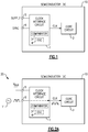
- FIG 1 is a schematic diagram of a semiconductor die 10 according to one embodiment.
- the semiconductor die 10 includes a clock interface circuit 1, a core circuit 2, a supply voltage pin 5 (SUPPLY), and a clock interface pin 6 (SYNC).
- a semiconductor die, such as the semiconductor die 10 of Figure 1 is also referred to herein as a semiconductor chip or integrated circuit (IC).
- the supply voltage pin 5 and the clock interface pin 6 correspond to pins (for instance, bond pads) of the semiconductor die 10. Although depicted as including only two pins, the semiconductor die 10 typically includes additional pins as well as additional circuitry for achieving desired operation or functionality. Such details have been omitted from Figure 1 for clarity.
- the semiconductor die 10 includes the core circuit 2, which has timing controlled by a clock signal CLK provided by the clock interface circuit 1.
- the performance of the core circuit 2 is impacted by a number of operational parameters of the clock signal CLK, including, but not limited to, frequency, phase, and/or noise.
- the core circuit 2 can correspond to a wide variety of circuits.
- examples of circuitry that can included in the core circuit 2 includes data converters, digital circuits, amplifiers, frequency synthesizers, voltage regulators, and/or data communication circuits.
- the clock interface circuits herein can provide a clock signal to a wide variety of types of circuits.
- the desired properties of the clock signal CLK can vary from one application to another. Furthermore, it is desirable for the semiconductor die 10 to be used across a wide range of applications, without needing to custom-design the semiconductor die 10 to have clock signal characteristics suitable for one particular application.
- the semiconductor die 10 includes the clock interface circuit 1, which is coupled to the supply voltage pin 5 and the clock interface pin 6, in this embodiment.
- the clock interface circuit 1 senses an electrical characteristic of the clock interface pin 6, and chooses a clock control mode for controlling the clock signal CLK based on the sensed characteristic.
- the clock interface circuit 1 of Figure 1 includes a comparator 3, which compares an electrical characteristic (for instance, a voltage level) of the clock interface pin 6 to a comparison threshold. Additionally, the result of the comparison is used to set the clock interface circuit 1 in the selected clock control mode.
- the comparison threshold of the comparator 3 is generated based on a voltage level of the supply voltage pin 5.
- the supply voltage pin 5 can correspond to any supply voltage pin, including a positive supply voltage pin, a negative supply voltage pin, or a ground pin.
- the clock interface circuit 1 further includes an oscillator 4, which generates an internal oscillator signal when enabled.
- the clock interface circuit 1 of Figure 1 is operable in two or more clock control modes, including at least a first clock control mode in which the clock interface circuit 1 generates the clock signal CLK based on an input clock signal received on the clock interface pin 6, and a second clock control mode in which the clock interface circuit 1 generates the clock signal CLK based on the oscillator signal from the oscillator 4.
- the selected clock control mode is chosen based on the comparison of the comparator 3.
- the voltage level of the clock interface pin 6 is used to tune an oscillation frequency of the oscillator 4.
- flexibility is further enhanced by providing a mechanism for the clock interface circuit's oscillator 4 to be tuned.
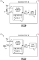
- FIG. 2A is a schematic diagram depicting one example of a first clock control mode 20 of the semiconductor die 10 of Figure 1 . As shown in Figure 2A , a supply voltage V sup has been supplied to the supply voltage pin 5, and an external clock source 11 has provided an input clock signal to clock interface pin 6.
- the clock interface control circuit 1 operates in the first clock control mode in this configuration.
- the input clock signal provided to the clock interface pin 6 is used to generate the clock signal CLK for the core circuit 2.
- the clock signal CLK corresponds to a buffered version of input clock signal, and thus has the same frequency.
- the comparator 3 compares a voltage level of the clock interface pin 6 to a threshold voltage, and sets the selected clock control mode based on a result of the comparison. Additionally, the clock source 11 controls a voltage level of the input clock signal, including both when the input clock signal is at a peak amplitude level and a minimum amplitude level, to be below or above the threshold voltage of the comparator 3 such that the output of the comparator 3 does not change as the input clock signal toggles.
- the clock source 11 sets a voltage level of the clock interface pin 6 to inform the clock interface circuit 1 to operate in the first clock control mode. Additionally, the clock source 11 provides the input clock signal to the clock interface circuit 1, which is used by the clock interface circuit 1 to generate the clock signal CLK for the core circuit 2.
- the frequency of the input clock signal can be changed as needed, and/or stopped and resumed as desired.
- the clock source 11 need not generate the input clock signal to be of fixed frequency.
- the clock source 11 can enable or disable the input clock signal as desired.
- FIG. 2B is a schematic diagram depicting one example of a second clock control mode 30 of the semiconductor die 10 of Figure 1 . As shown in Figure 2B , a supply voltage V sup has been supplied to the supply voltage pin 5, and an external resistor 21 has been connected between the supply voltage pin 5 and the clock interface pin 6.
- the clock interface control circuit 1 operates in the second clock control mode in this configuration.
- an internal oscillator signal from the oscillator 4 is used to generate the clock signal CLK for the core circuit 2.
- a voltage V EXT at the clock interface pin 6 is used to set an oscillation frequency of the internal oscillator signal, and thus the frequency of the clock signal CLK.
- a resistor value corresponding to a desired oscillation frequency of the oscillator 4 can be chosen for connecting between the supply pin 5 and the clock interface pin 6.
- the end-user can instruct the clock interface circuit 1 to use the oscillator 4 to generate the clock signal CLK, with the resistance value used to set V EXT and thus the oscillation frequency of the oscillator 4.
- a wide range of external control circuits can be used to set the voltage level V EXT of the clock interface pin 6.
- the second clock control mode can be set in other ways.
- the DAC 31 provides enhanced flexibility in tuning or adjusting the oscillation frequency of the oscillator 4.
- the DAC 31 can be suitable for applications in which it is desirable to dynamically change the oscillation frequency of the oscillator 4, for instance, in applications in which the operational frequency changes over time and/or in applications in which the oscillation frequency is adjusted to account for variation in operating conditions, such as temperature and/or supply voltage.
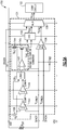
- FIG. 3 is a schematic diagram of a semiconductor die 120 including clock interface circuitry according to another embodiment.
- the semiconductor die 120 includes a clock interface circuit 101, a core circuit 102, a power high supply pin VDD, a power low supply pin VSS, a first clock interface pin SYNCP, and a second clock interface pin SYNCN.
- the clock interface circuit 101 includes a first hysteretic comparator 103, a second hysteretic comparator 104, a digital logic circuit 105, a clock buffer 106, an oscillator 107, a multiplexer 108, and a reference voltage source 109.
- the reference voltage source 109 generates a reference voltage for the first hysteretic comparator 103 and the second hysteretic comparator 104 based on shifting the supply voltage received on the power high supply pin VDD.
- the reference voltage corresponds to V DD - V B , where V DD is the voltage level of the power high supply pin VDD and V B is the voltage of the reference voltage source 109.
- the first hysteretic comparator 103 generates a first comparison signal COMPP based on comparing the voltage level of the first clock interface pin SYNCP to the reference voltage, while the second hysteretic comparator 104 generates a second comparison signal COMPN based on comparing the voltage level of the second clock interface pin SYNCN to the reference voltage.
- the digital logic circuit 105 processes the first comparison signal COMPP and the second comparison signal COMPN to generate an oscillator enable signal OSCEN, which is used to both enable the oscillator 107 and to control selection of the multiplexer 108.
- the clock buffer 106 includes a differential input connected to the first clock interface pin SYNCP and the second clock interface pin SYNCN.
- the clock buffer 106 further includes an output that provides a synchronized clock signal V SYNC to a first signal input of the multiplexer 108.
- the oscillator 107 provides an oscillator signal Vosc to a second signal input of the multiplexer 108.
- the multiplexer 108 outputs a clock signal V CLK to the core circuit 102.
- the first hysteretic comparator 103 and the second hysteretic comparator 104 compare the reference voltage from the reference voltage source 109 to the voltage level of the first clock interface pin SYNCP and the second clock interface pin SYNCN, respectively.
- Using hysteretic comparators provides a number of advantages, such as providing hysteresis to inhibit noise from inadvertently changing the result of the comparisons during operation.
- the digital logic circuit 105 sets the clock interface circuit 101 in either a first clock control mode or a second clock control mode.
- the voltage levels of the first clock interface pin SYNCP and the second clock interface pin SYNC relative to the reference voltage used for comparison determine whether the clock interface circuit 101 operates in the first clock control mode or the second clock control mode.
- the second clock control mode is chosen when the voltage levels of the clock interface pins are both greater than the reference voltage, otherwise the first clock control mode is chosen.
- the oscillator 107 when operating in the first clock control mode, the oscillator 107 is disabled, and the synchronized clock signal V SYNC is selected by the multiplexer 108 to serve as the clock signal V CLK for the core circuit 102. Aside from a delay of the clock buffer 106, the synchronized clock signal V SYNC is synchronized to a differential input clock signal received between the first clock interface pin SYNCP and the second clock interface pin SYNCN.
- Using a pair of differential clock interface pins allows a differential input clock signal to be supplied in the first clock control mode, which provides the advantage of lower clock noise and/or reduced jitter relative to a single-ended configuration.
- the oscillator 107 when operating in the second clock control mode, the oscillator 107 is enabled, and the oscillator signal Vosc is selected by the multiplexer 108 to serve as the clock signal V CLK for the core circuit 102.
- the frequency of the oscillator 107 is not tuned by the voltage level(s) of the clock interface pins.
- FIG. 4 is a schematic diagram of a semiconductor die 130 including clock interface circuitry according to another embodiment.
- the semiconductor die 130 includes a clock interface circuit 121, a core circuit 102, a power high supply pin VDD, a power low supply pin VSS, and a clock interface pin SYNCP.
- the clock interface circuit 121 includes a hysteretic comparator 103, a digital logic circuit 105, a clock buffer 106, an oscillator 107, a multiplexer 108, a first reference voltage source 109, and a second reference voltage source 129.
- the semiconductor die 130 of Figure 4 omits the second clock interface pin SYNCN and the second hysteretic comparator 104. Additionally, the clock interface circuit 121 of Figure 4 includes the second reference voltage source 129 for generating a clock buffer reference voltage for the clock buffer 106.
- the second reference voltage source 129 generates the clock buffer reference voltage based on shifting the supply voltage received on the power low supply pin VSS.
- the clock buffer reference voltage corresponds to V SS + V BN , where Vss is the voltage level of the power low supply pin VSS and V BN is the voltage of the second reference voltage source 129.
- the synchronized clock signal VSYNC corresponds to a buffered version of a single-ended input clock signal received on the clock interface pin VSYNCP.
- the semiconductor die 130 has fewer clock interface pins but is more susceptible to noise in the first clock control mode.
- FIG. 5A is a schematic diagram of a semiconductor die 150 including clock interface circuitry according to another embodiment.
- the semiconductor die 150 includes a clock interface circuit 131, a core circuit 102, a power high supply pin VDD, a power low supply pin VSS, a first clock interface pin SYNCP, and a second clock interface pin SYNCN.
- the clock interface circuit 131 includes a first hysteretic comparator 103, a second hysteretic comparator 104, a digital logic circuit 105, a clock buffer 106, a multiplexer 108, a reference voltage source 109, a voltage-to-current converter 141, an oscillator 142, and a current source I REF .
- the voltage-to-current converter 141 include an amplifier 143, a reference resistor 144 (with resistance R REF ), and a transistor 145.
- the clock interface circuit 131 of Figure 5A further includes the voltage-to-current converter 141 and the current source I REF .
- the current source I REF When operating in the second clock control mode, the current source I REF is enabled and the voltage-to-current converter 141 generates a control current I OSC_Ctrl that changes in relation to the voltage level of the first clock interface pin SYNCP.
- the control current I OSC_Ctrl is used to tune the oscillation frequency of the oscillator 142.
- the voltage level of the first clock interface pin SYNCP is used to tune the frequency of the oscillator 142 and thus the frequency of the clock signal VCLK provided to the core circuit 102.
- flexibility is enhanced by providing a mechanism for oscillator frequency control.
- control current I OSC_Ctrl I REF ⁇ R EXT /R REF , and thus the control current I OSC_Ctrl increases with the external resistor's resistance.
- the voltage level of the first clock interface pin SYNCP is set using an external resistor R EXT .
- R EXT external resistor
- Figure 5B is one example of a graph depicting operation of the semiconductor die 150 of Figure 5A .
- the graph depicts a first time period depicting operation in the first clock control mode with the input clock signal toggling. Additionally, the graph depicts a second time period depicting operation in the first clock control mode with the input clock signal not toggling.
- the frequency of the input clock signal can be changed as needed, and/or the input clock signal can be stopped and resumed as desired.
- the graph further includes a third time period depicting operation in the second clock control mode with a small resistance value R EXT . Furthermore, the graph further includes a fourth time period depicting operation in the second clock control mode with a large resistance value R EXT . As shown in Figure 5B , when operating in the second clock control mode, the frequency of clock interface control circuit's oscillator can be tuned based on a resistance value selected for an external resistor.
- FIG. 6 is a schematic diagram of a semiconductor die 160 including clock interface circuitry according to another embodiment.
- the semiconductor die 160 includes a clock interface circuit 151, a core circuit 102, a power high supply pin VDD, a power low supply pin VSS, a first clock interface pin SYNCP, and a second clock interface pin SYNCN.
- the clock interface circuit 151 includes a first hysteretic comparator 103, a second hysteretic comparator 104, a digital logic circuit 105, a clock buffer 106, a multiplexer 108, a reference voltage source 109, a voltage-to-current converter 141, a current source I REF , an oscillator 152, and an ADC 153.
- the clock interface circuit 151 of Figure 6 is similar to the clock interface circuit 131 of Figure 5A , except that the clock interface circuit 151 further includes an ADC 153 for digitizing the controllable current from the current-to-voltage converter 141. Additionally, the ADC 153 provides a digital tuning signal to the oscillator 152.
- digital tuning of the oscillator 152 is provided.
- Using digital tuning provides a number of advantages, including, but not limited to, flexibility in digitally processing the digital control signal using any desired processing, such as shaping, compensation for variation, and/or other processing.
- FIGS 7A-7D depict various examples of core circuits receiving a clock signal from a clock interface circuit. Although various applications of clock interface circuits are depicted, clock interface circuits can be used to generate a clock signal for a wide variety of core circuits. Accordingly, other implementations are possible.
- FIG 7A is a schematic diagram of another embodiment of a semiconductor die 210.
- the semiconductor die 210 includes a clock interface circuit 191 and a chopper amplifier 192. Pins coupled to the clock interface circuit 191 and components of the clock interface circuit 191 are not depicted in Figure 7A for clarity of the figure. However, the clock interface circuit 191 can be implemented in accordance with any of the embodiments herein.
- the chopper amplifier 192 includes an input chopping circuit 201, an amplification circuit 202, and an output chopping circuit 203 electrically connected along a differential signal path between a pair of input terminals (V IN+ , V IN- ) and a pair of output terminals (V OUT+ , V OUT- ).
- the clock interface circuit 191 generates a clock signal CLK, which is used to control chopping operations of the input chopping circuit 201 and the output chopping circuit 203.
- the input chopping circuit 201 When operating in the first clock control mode, the input chopping circuit 201 can be controlled by an input clock signal that is synchronized with external components (for instance, an ADC that digitizes an output voltage of the chopper amplifier 192), thereby avoiding aliasing. Additionally, when operating in the first clock control mode, the input clock signal can be stopped as desired to provide continuous amplification without chopping, and then resumed when chopping is desired.
- external components for instance, an ADC that digitizes an output voltage of the chopper amplifier 192
- an oscillator of the clock interface circuit 191 when operating in the second clock control mode, generates the clock signal CLK.
- chopping can be controlled using an internal self-clock, which can be tunable to a user-selected frequency by setting a voltage level of a clock interface pin.
- FIG 7B is a schematic diagram of another embodiment of a semiconductor die 220.
- the semiconductor die 220 includes a clock interface circuit 191 and an ADC 212. Pins coupled to the clock interface circuit 191 and components of the clock interface circuit 191 are not depicted in Figure 7B for clarity of the figure.
- the clock interface circuit 191 can be implemented in accordance with any of the embodiments herein.
- the ADC 212 receives an input signal IN and generates a digital output signal DOUT. Timing of data conversion operations of the ADC 212 is controlled by the clock signal CLK from the clock interface circuit 191.
- FIG. 7C is a schematic diagram of another embodiment of a semiconductor die 230.
- the semiconductor die 230 includes a clock interface circuit 191 and a DAC 222. Pins coupled to the clock interface circuit 191 and components of the clock interface circuit 191 are not depicted in Figure 7C for clarity of the figure. However, the clock interface circuit 191 can be implemented in accordance with any of the embodiments herein.
- the DAC 222 receives a digital input signal DIN and generates an output signal OUT. Timing of data conversion operations of the DAC 222 is controlled by the clock signal CLK from the clock interface circuit 191.
- FIG. 7D is a schematic diagram of another embodiment of a semiconductor die 240.
- the semiconductor die 240 includes a clock interface circuit 191 and a switching regulator 232. Pins coupled to the clock interface circuit 191 and components of the clock interface circuit 191 are not depicted in Figure 7D for clarity of the figure. However, the clock interface circuit 191 can be implemented in accordance with any of the embodiments herein.
- the switching regulator 232 generates a regulated voltage V REG based on timing of the clock signal CLK from the clock interface circuit 191.
- switches of the switching regulator 232 can be opened or closed to control regulation.
- the switching regulator 232 can correspond to a buck converter or boost converter having switches used to control a current delivered to an inductor.
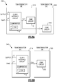
- FIG 8A is a schematic diagram of an electronic system 330 according to another embodiment.
- the electronic system 330 includes a first semiconductor die 318 and a second semiconductor die 320.
- the first semiconductor die 318 is similar to the semiconductor die 10 of Figure 1 , except that the semiconductor die 318 of Figure 8A also outputs the clock signal CLK on a clock output pin. As shown in Figure 8A , the clock signal CLK is provided from the first semiconductor die 318 to a core circuit 302 of the second semiconductor die 320. In certain implementations, the first semiconductor die 318 and the second semiconductor die 320 are co-packaged on a module.
- Figure 8B is a schematic diagram of an electronic system 340 according to another embodiment.
- the electronic system 340 includes a first semiconductor die 319 and a second semiconductor die 320.
- the first semiconductor die 319 of Figure 8B is similar to the first semiconductor die 318 of Figure 8A , except that the semiconductor die 319 of Figure 8B omits the core circuit 2. Thus, the first semiconductor die 319 does not include the core circuit 2, but rather outputs the clock signal CLK on a clock output pin to provide the core circuit 302 of the second semiconductor die 320.
- Devices employing the above described schemes can be implemented into various electronic devices.
- Examples of electronic devices include, but are not limited to, consumer electronic products, electronic test equipment, communication systems, data converters, etc.
Landscapes
- Engineering & Computer Science (AREA)
- Theoretical Computer Science (AREA)
- Physics & Mathematics (AREA)
- General Engineering & Computer Science (AREA)
- General Physics & Mathematics (AREA)
- Nonlinear Science (AREA)
- Semiconductor Integrated Circuits (AREA)
- Dc-Dc Converters (AREA)
Abstract
Description
- Embodiments of the invention relate to electronic systems, and more particularly, to clock interface circuits for integrated circuits (ICs).
- A wide variety of electronic systems operate based on timing of clock signals. For instance, examples of electronic circuitry that operate based on clock signal timing include, but are not limited to, analog-to-digital converters (ADCs), digital-to-analog converters (DACs), data communication links, amplifiers, digital circuits, and/or voltage regulators.
- Apparatus and methods for controlling a clock signal are provided. In certain embodiments, a semiconductor die includes a core circuit and a clock interface circuit that provides a clock signal to the core circuit. The semiconductor die further includes multiple pins or pads, including at least a supply voltage pin and a clock interface pin coupled to the clock interface circuit. The clock interface circuit includes an oscillator for generating an oscillator signal, and a comparator for controlling operation of the clock interface circuit in a selected clock control mode chosen from two or more clock control modes based on comparing an electrical characteristic of the clock interface pin to a comparison threshold. The two or more clock control modes include a first clock control mode in which the clock interface circuit generates the clock signal based on an input clock signal received on the clock interface pin, and a second clock control mode in which the clock interface circuit generates the clock signal based on the oscillator signal. Accordingly, the clock interface circuit provides flexibility in controlling the clock signal provided to the core circuit.
- In one aspect, a semiconductor die with clock control is provided. The semiconductor die includes a plurality of pins including a supply pin and a first clock interface pin. The semiconductor die further includes a clock interface circuit configured to output a clock signal, the clock interface circuit coupled to the supply pin and the first clock interface pin. The clock interface circuit includes an oscillator configured to generate an oscillator signal, and a first comparator configured to control operation of the clock interface circuit in a selected clock control mode chosen from two or more clock control modes based on comparing an electrical characteristic of the first clock interface pin to a comparison threshold. The two or more clock control modes includes a first clock control mode in which the clock interface circuit generates the clock signal based on an input clock signal received on the clock interface pin, and a second clock control mode in which the clock interface circuit generates the clock signal based on the oscillator signal.
- In another aspect, a method of clock control in an electronic system is provided. The method includes controlling timing of a core circuit using a clock signal provided by a clock interface circuit coupled to a supply pin and a first clock interface pin, comparing an electrical characteristic of the first clock interface pin to a comparison threshold using a comparator of the clock interface circuit, and operating the clock interface circuit in a selected clock control mode chosen from two or more clock control modes based on the comparison, including generating the clock signal based on an input clock signal received on the clock interface pin in a first clock control mode, and generating the clock signal using an oscillator of the clock interface circuit in a second clock control mode.
- In another aspect, an electronic system is provided. The electronic system includes a power supply configured to generate a supply voltage, and a first semiconductor die. The first semiconductor die includes a supply pin configured to receive the supply voltage, a clock interface pin, and a clock interface circuit configured to output a clock signal. The clock interface circuit includes an oscillator configured to generate an oscillator signal, and a first comparator configured to control operation of the clock interface circuit in a selected clock control mode chosen from two or more clock control modes based on comparing an electrical characteristic of the first clock interface pin to a comparison threshold. The two or more clock control modes includes a first clock control mode in which the clock interface circuit generates the clock signal based on an input clock signal received on the clock interface pin, and a second clock control mode in which the clock interface circuit generates the clock signal based on the oscillator signal.
-
-
Figure 1 is a schematic diagram of a semiconductor die including clock interface circuitry according to one embodiment. -
Figure 2A is a schematic diagram depicting one example of a first clock control mode of the semiconductor die ofFigure 1 . -
Figure 2B is a schematic diagram depicting one example of a second clock control mode of the semiconductor die ofFigure 1 . -
Figure 2C is a schematic diagram depicting another example of the second clock control mode of the semiconductor die ofFigure 1 . -
Figure 3 is a schematic diagram of a semiconductor die including clock interface circuitry according to another embodiment. -
Figure 4 is a schematic diagram of a semiconductor die including clock interface circuitry according to another embodiment. -
Figure 5A is a schematic diagram of a semiconductor die including clock interface circuitry according to another embodiment. -
Figure 5B is one example of a graph depicting operation of the semiconductor die ofFigure 5A . -
Figure 6 is a schematic diagram of a semiconductor die including clock interface circuitry according to another embodiment. -
Figure 7A is a schematic diagram of another embodiment of a semiconductor die. -
Figure 7B is a schematic diagram of another embodiment of a semiconductor die. -
Figure 7C is a schematic diagram of another embodiment of a semiconductor die. -
Figure 7D is a schematic diagram of another embodiment of a semiconductor die. -
Figure 8A is a schematic diagram of an electronic system according to another embodiment. -
Figure 8B is a schematic diagram of an electronic system according to another embodiment. - The following detailed description of embodiments presents various descriptions of specific embodiments of the invention. However, the invention can be embodied in a multitude of different ways. In this description, reference is made to the drawings where like reference numerals may indicate identical or functionally similar elements. It will be understood that elements illustrated in the figures are not necessarily drawn to scale. Moreover, it will be understood that certain embodiments can include more elements than illustrated in a drawing and/or a subset of the elements illustrated in a drawing. Further, some embodiments can incorporate any suitable combination of features from two or more drawings.
- Apparatus and methods for controlling a clock signal are provided. In certain embodiments, a semiconductor die includes a core circuit and a clock interface circuit that provides a clock signal to the core circuit. The semiconductor die further includes multiple pins or pads, including at least a supply voltage pin and a clock interface pin coupled to the clock interface circuit. The clock interface circuit includes an oscillator for generating an oscillator signal, and a comparator for controlling operation of the clock interface circuit in a selected clock control mode chosen from two or more clock control modes based on comparing an electrical characteristic of the clock interface pin to a comparison threshold. The two or more clock control modes include a first clock control mode in which the clock interface circuit generates the clock signal based on an input clock signal received on the clock interface pin, and a second clock control mode in which the clock interface circuit generates the clock signal based on the oscillator signal.
- Accordingly, the clock interface circuit provides flexibility in controlling the clock signal provided to the core circuit.
- For example, using the first clock control mode, the semiconductor die can be deployed in a first application in which it is desirable for the core circuit to be clocked using an input clock signal provided to the clock interface pin. For instance, the core circuit can communicate with another circuit external to the semiconductor die (for instance, a data converter), and a common clock signal can be used to control timing of both the core circuit and the external circuit to avoid intermodulation-distortion and/or aliasing. When operating in the first clock control mode, the frequency of the input clock signal can be changed as needed, and/or stopped and resumed as desired.
- Furthermore, using the second clock control mode, the semiconductor die can further be deployed in a second application in which the clock interface circuit's oscillator generates the clock signal for the core circuit. For instance, in certain use cases a default oscillation frequency of the oscillator may be suitable for clocking the core circuit, thereby reducing cost by avoiding a need for an external clock source.
- Accordingly, the clock interface circuit provides enhanced flexibility to enable the same semiconductor die to be used in a wide range of applications. Thus, a need to manufacture many different types of semiconductor dies each with a custom clock design is avoided.
- In certain implementations, the comparison threshold of the comparator is generated based on a voltage level of the supply voltage pin. For example, the clock interface circuit can include a bias voltage source that shifts the supply voltage to generate a reference voltage for serving as the comparison threshold.
- Implementing the clock interface circuit in this manner provides a number of advantages, including an ability to operate the clock interface circuit in the second clock control mode by tying the clock interface pin to the supply voltage pin, either directly or through an impedance (for instance, an external resistor).
- In certain implementations, when operating in the second clock control mode, the voltage level of the clock interface pin is used to tune an oscillation frequency of the oscillator. In such implementations, flexibility is further enhanced by providing a mechanism for the clock interface circuit's oscillator to be tuned.
- The voltage level of the clock interface pin can be set to a desired voltage level in a wide variety of ways, such as by connecting a resistor of a particular resistance between the supply voltage pin and the clock interface pin, thereby setting the voltage level of the clock interface pin to a particular voltage level corresponding to the desired oscillation frequency. In another example, a digital-to-analog convert (DAC) or other external control circuit sets the tuning voltage, which can be changed over time to achieve a desired oscillation frequency.
- In certain implementations, the clock interface circuit includes multiple clock interface pins, for instance, a pair of clock interface pins that are implemented differentially. For example, using a pair of differential clock interface pins allows a differential input clock signal to be supplied in the first clock control mode, which provides the advantage of lower clock noise and/or reduced jitter relative to a single-ended configuration.
- In the embodiments described above, the core circuit is integrated on the same semiconductor die as the clock interface circuit. However, other configurations are possible. In another embodiment, the clock interface circuit and the core circuit are on separate semiconductor dies, which can be co-packaged in a module. In yet another embodiment, the core circuit is integrated on-chip with the clock interface circuit, but the clock signal is also provided off-chip for an external component, which can be, for example, a core circuit of another semiconductor die.
-
Figure 1 is a schematic diagram of asemiconductor die 10 according to one embodiment. The semiconductor die 10 includes a clock interface circuit 1, acore circuit 2, a supply voltage pin 5 (SUPPLY), and a clock interface pin 6 (SYNC). A semiconductor die, such as the semiconductor die 10 ofFigure 1 , is also referred to herein as a semiconductor chip or integrated circuit (IC). - The
supply voltage pin 5 and theclock interface pin 6 correspond to pins (for instance, bond pads) of the semiconductor die 10. Although depicted as including only two pins, the semiconductor die 10 typically includes additional pins as well as additional circuitry for achieving desired operation or functionality. Such details have been omitted fromFigure 1 for clarity. - As shown in
Figure 1 , the semiconductor die 10 includes thecore circuit 2, which has timing controlled by a clock signal CLK provided by the clock interface circuit 1. The performance of thecore circuit 2 is impacted by a number of operational parameters of the clock signal CLK, including, but not limited to, frequency, phase, and/or noise. - The
core circuit 2 can correspond to a wide variety of circuits. For instance, examples of circuitry that can included in thecore circuit 2 includes data converters, digital circuits, amplifiers, frequency synthesizers, voltage regulators, and/or data communication circuits. The clock interface circuits herein can provide a clock signal to a wide variety of types of circuits. - The desired properties of the clock signal CLK (such as frequency) can vary from one application to another. Furthermore, it is desirable for the semiconductor die 10 to be used across a wide range of applications, without needing to custom-design the semiconductor die 10 to have clock signal characteristics suitable for one particular application.
- To provide flexibility in controlling the clock signal CLK, the semiconductor die 10 includes the clock interface circuit 1, which is coupled to the
supply voltage pin 5 and theclock interface pin 6, in this embodiment. The clock interface circuit 1 senses an electrical characteristic of theclock interface pin 6, and chooses a clock control mode for controlling the clock signal CLK based on the sensed characteristic. - For example, the clock interface circuit 1 of
Figure 1 includes acomparator 3, which compares an electrical characteristic (for instance, a voltage level) of theclock interface pin 6 to a comparison threshold. Additionally, the result of the comparison is used to set the clock interface circuit 1 in the selected clock control mode. In certain implementations, the comparison threshold of thecomparator 3 is generated based on a voltage level of thesupply voltage pin 5. Thesupply voltage pin 5 can correspond to any supply voltage pin, including a positive supply voltage pin, a negative supply voltage pin, or a ground pin. - With continuing reference to
Figure 1 , the clock interface circuit 1 further includes anoscillator 4, which generates an internal oscillator signal when enabled. - The clock interface circuit 1 of
Figure 1 is operable in two or more clock control modes, including at least a first clock control mode in which the clock interface circuit 1 generates the clock signal CLK based on an input clock signal received on theclock interface pin 6, and a second clock control mode in which the clock interface circuit 1 generates the clock signal CLK based on the oscillator signal from theoscillator 4. The selected clock control mode is chosen based on the comparison of thecomparator 3. - In certain implementations, when operating in the second clock control mode, the voltage level of the
clock interface pin 6 is used to tune an oscillation frequency of theoscillator 4. In such implementations, flexibility is further enhanced by providing a mechanism for the clock interface circuit'soscillator 4 to be tuned. -
Figure 2A is a schematic diagram depicting one example of a firstclock control mode 20 of the semiconductor die 10 ofFigure 1 . As shown inFigure 2A , a supply voltage Vsup has been supplied to thesupply voltage pin 5, and anexternal clock source 11 has provided an input clock signal toclock interface pin 6. - The clock interface control circuit 1 operates in the first clock control mode in this configuration. Thus, the input clock signal provided to the
clock interface pin 6 is used to generate the clock signal CLK for thecore circuit 2. In certain implementations, when operating the first clock control mode, the clock signal CLK corresponds to a buffered version of input clock signal, and thus has the same frequency. - In certain implementations, the
comparator 3 compares a voltage level of theclock interface pin 6 to a threshold voltage, and sets the selected clock control mode based on a result of the comparison. Additionally, theclock source 11 controls a voltage level of the input clock signal, including both when the input clock signal is at a peak amplitude level and a minimum amplitude level, to be below or above the threshold voltage of thecomparator 3 such that the output of thecomparator 3 does not change as the input clock signal toggles. - Thus, the
clock source 11 sets a voltage level of theclock interface pin 6 to inform the clock interface circuit 1 to operate in the first clock control mode. Additionally, theclock source 11 provides the input clock signal to the clock interface circuit 1, which is used by the clock interface circuit 1 to generate the clock signal CLK for thecore circuit 2. - When operating in the first clock control mode, the frequency of the input clock signal can be changed as needed, and/or stopped and resumed as desired. Thus, the
clock source 11 need not generate the input clock signal to be of fixed frequency. Moreover, theclock source 11 can enable or disable the input clock signal as desired. -
Figure 2B is a schematic diagram depicting one example of a secondclock control mode 30 of the semiconductor die 10 ofFigure 1 . As shown inFigure 2B , a supply voltage Vsup has been supplied to thesupply voltage pin 5, and anexternal resistor 21 has been connected between thesupply voltage pin 5 and theclock interface pin 6. - The clock interface control circuit 1 operates in the second clock control mode in this configuration. Thus, an internal oscillator signal from the
oscillator 4 is used to generate the clock signal CLK for thecore circuit 2. - In certain implementations, when operating in the second clock control mode, a voltage VEXT at the
clock interface pin 6 is used to set an oscillation frequency of the internal oscillator signal, and thus the frequency of the clock signal CLK. - In such implementations, a resistor value corresponding to a desired oscillation frequency of the
oscillator 4 can be chosen for connecting between thesupply pin 5 and theclock interface pin 6. Thus, by simply choosing a resistor of a particular resistance, the end-user can instruct the clock interface circuit 1 to use theoscillator 4 to generate the clock signal CLK, with the resistance value used to set VEXT and thus the oscillation frequency of theoscillator 4. -
Figure 2C is a schematic diagram depicting another example of the secondclock control mode 40 of the semiconductor die 10 ofFigure 1 . In comparison to the example ofFigure 2B , aDAC 31 is used to set the voltage level VEXT of theclock interface pin 6 rather than a resistor. - A wide range of external control circuits can be used to set the voltage level VEXT of the
clock interface pin 6. Thus, although examples using a resistor and a DAC have been depicted inFigures 2B and 2C , the second clock control mode can be set in other ways. - In the illustrated embodiment, the
DAC 31 provides enhanced flexibility in tuning or adjusting the oscillation frequency of theoscillator 4. Thus, theDAC 31 can be suitable for applications in which it is desirable to dynamically change the oscillation frequency of theoscillator 4, for instance, in applications in which the operational frequency changes over time and/or in applications in which the oscillation frequency is adjusted to account for variation in operating conditions, such as temperature and/or supply voltage. -
Figure 3 is a schematic diagram of asemiconductor die 120 including clock interface circuitry according to another embodiment. The semiconductor die 120 includes aclock interface circuit 101, acore circuit 102, a power high supply pin VDD, a power low supply pin VSS, a first clock interface pin SYNCP, and a second clock interface pin SYNCN. - In the illustrated embodiment, the
clock interface circuit 101 includes a firsthysteretic comparator 103, a secondhysteretic comparator 104, adigital logic circuit 105, aclock buffer 106, anoscillator 107, amultiplexer 108, and areference voltage source 109. - As shown in
Figure 3 , thereference voltage source 109 generates a reference voltage for the firsthysteretic comparator 103 and the secondhysteretic comparator 104 based on shifting the supply voltage received on the power high supply pin VDD. For example, in certain implementations, the reference voltage corresponds to VDD - VB, where VDD is the voltage level of the power high supply pin VDD and VB is the voltage of thereference voltage source 109. - The first
hysteretic comparator 103 generates a first comparison signal COMPP based on comparing the voltage level of the first clock interface pin SYNCP to the reference voltage, while the secondhysteretic comparator 104 generates a second comparison signal COMPN based on comparing the voltage level of the second clock interface pin SYNCN to the reference voltage. - With continuing reference to
Figure 3 , thedigital logic circuit 105 processes the first comparison signal COMPP and the second comparison signal COMPN to generate an oscillator enable signal OSCEN, which is used to both enable theoscillator 107 and to control selection of themultiplexer 108. - The
clock buffer 106 includes a differential input connected to the first clock interface pin SYNCP and the second clock interface pin SYNCN. Theclock buffer 106 further includes an output that provides a synchronized clock signal VSYNC to a first signal input of themultiplexer 108. When enabled, theoscillator 107 provides an oscillator signal Vosc to a second signal input of themultiplexer 108. Themultiplexer 108 outputs a clock signal VCLK to thecore circuit 102. - In the illustrated embodiment, the first
hysteretic comparator 103 and the secondhysteretic comparator 104 compare the reference voltage from thereference voltage source 109 to the voltage level of the first clock interface pin SYNCP and the second clock interface pin SYNCN, respectively. Using hysteretic comparators provides a number of advantages, such as providing hysteresis to inhibit noise from inadvertently changing the result of the comparisons during operation. - Based on the result of the comparisons, the
digital logic circuit 105 sets theclock interface circuit 101 in either a first clock control mode or a second clock control mode. Thus, the voltage levels of the first clock interface pin SYNCP and the second clock interface pin SYNC relative to the reference voltage used for comparison determine whether theclock interface circuit 101 operates in the first clock control mode or the second clock control mode. In certain implementations, the second clock control mode is chosen when the voltage levels of the clock interface pins are both greater than the reference voltage, otherwise the first clock control mode is chosen. - In the illustrated embodiment, when operating in the first clock control mode, the
oscillator 107 is disabled, and the synchronized clock signal VSYNC is selected by themultiplexer 108 to serve as the clock signal VCLK for thecore circuit 102. Aside from a delay of theclock buffer 106, the synchronized clock signal VSYNC is synchronized to a differential input clock signal received between the first clock interface pin SYNCP and the second clock interface pin SYNCN. Using a pair of differential clock interface pins allows a differential input clock signal to be supplied in the first clock control mode, which provides the advantage of lower clock noise and/or reduced jitter relative to a single-ended configuration. - With continuing reference to
Figure 3 , when operating in the second clock control mode, theoscillator 107 is enabled, and the oscillator signal Vosc is selected by themultiplexer 108 to serve as the clock signal VCLK for thecore circuit 102. In this embodiment, the frequency of theoscillator 107 is not tuned by the voltage level(s) of the clock interface pins. -
Figure 4 is a schematic diagram of asemiconductor die 130 including clock interface circuitry according to another embodiment. The semiconductor die 130 includes aclock interface circuit 121, acore circuit 102, a power high supply pin VDD, a power low supply pin VSS, and a clock interface pin SYNCP. Theclock interface circuit 121 includes ahysteretic comparator 103, adigital logic circuit 105, aclock buffer 106, anoscillator 107, amultiplexer 108, a firstreference voltage source 109, and a secondreference voltage source 129. - In comparison to the semiconductor die 120 of
Figure 3 , the semiconductor die 130 ofFigure 4 omits the second clock interface pin SYNCN and the secondhysteretic comparator 104. Additionally, theclock interface circuit 121 ofFigure 4 includes the secondreference voltage source 129 for generating a clock buffer reference voltage for theclock buffer 106. - As shown in
Figure 4 , the secondreference voltage source 129 generates the clock buffer reference voltage based on shifting the supply voltage received on the power low supply pin VSS. For example, in certain implementations, the clock buffer reference voltage corresponds to VSS + VBN, where Vss is the voltage level of the power low supply pin VSS and VBN is the voltage of the secondreference voltage source 129. - When operating in the first clock control mode, the synchronized clock signal VSYNC corresponds to a buffered version of a single-ended input clock signal received on the clock interface pin VSYNCP. In comparison to the semiconductor die 120 of
Figure 3 , the semiconductor die 130 has fewer clock interface pins but is more susceptible to noise in the first clock control mode. -
Figure 5A is a schematic diagram of asemiconductor die 150 including clock interface circuitry according to another embodiment. The semiconductor die 150 includes aclock interface circuit 131, acore circuit 102, a power high supply pin VDD, a power low supply pin VSS, a first clock interface pin SYNCP, and a second clock interface pin SYNCN. Theclock interface circuit 131 includes a firsthysteretic comparator 103, a secondhysteretic comparator 104, adigital logic circuit 105, aclock buffer 106, amultiplexer 108, areference voltage source 109, a voltage-to-current converter 141, anoscillator 142, and a current source IREF. In the illustrated embodiment, the voltage-to-current converter 141 include anamplifier 143, a reference resistor 144 (with resistance RREF), and atransistor 145. - In comparison to the
clock interface circuit 101 ofFigure 3 , theclock interface circuit 131 ofFigure 5A further includes the voltage-to-current converter 141 and the current source IREF. When operating in the second clock control mode, the current source IREF is enabled and the voltage-to-current converter 141 generates a control current IOSC_Ctrl that changes in relation to the voltage level of the first clock interface pin SYNCP. The control current IOSC_Ctrl is used to tune the oscillation frequency of theoscillator 142. - Thus, when operating in the second clock control mode, the voltage level of the first clock interface pin SYNCP is used to tune the frequency of the
oscillator 142 and thus the frequency of the clock signal VCLK provided to thecore circuit 102. Thus, flexibility is enhanced by providing a mechanism for oscillator frequency control. - For example, one expression for the control current IOSC_Ctrl is IREF ∗REXT/RREF, and thus the control current IOSC_Ctrl increases with the external resistor's resistance.
- In the illustrated embodiment, the voltage level of the first clock interface pin SYNCP is set using an external resistor REXT. However, other implementations of setting of the voltage level of the first clock interface pin SYNCP are possible.
-
Figure 5B is one example of a graph depicting operation of the semiconductor die 150 ofFigure 5A . - The graph depicts a first time period depicting operation in the first clock control mode with the input clock signal toggling. Additionally, the graph depicts a second time period depicting operation in the first clock control mode with the input clock signal not toggling. As shown in
Figure 5B , when operating in the first clock control mode, the frequency of the input clock signal can be changed as needed, and/or the input clock signal can be stopped and resumed as desired. - With continuing reference to
Figure 5B , the graph further includes a third time period depicting operation in the second clock control mode with a small resistance value REXT. Furthermore, the graph further includes a fourth time period depicting operation in the second clock control mode with a large resistance value REXT. As shown inFigure 5B , when operating in the second clock control mode, the frequency of clock interface control circuit's oscillator can be tuned based on a resistance value selected for an external resistor. -
Figure 6 is a schematic diagram of asemiconductor die 160 including clock interface circuitry according to another embodiment. The semiconductor die 160 includes aclock interface circuit 151, acore circuit 102, a power high supply pin VDD, a power low supply pin VSS, a first clock interface pin SYNCP, and a second clock interface pin SYNCN. Theclock interface circuit 151 includes a firsthysteretic comparator 103, a secondhysteretic comparator 104, adigital logic circuit 105, aclock buffer 106, amultiplexer 108, areference voltage source 109, a voltage-to-current converter 141, a current source IREF, anoscillator 152, and anADC 153. - The
clock interface circuit 151 ofFigure 6 is similar to theclock interface circuit 131 ofFigure 5A , except that theclock interface circuit 151 further includes anADC 153 for digitizing the controllable current from the current-to-voltage converter 141. Additionally, theADC 153 provides a digital tuning signal to theoscillator 152. - Accordingly, digital tuning of the
oscillator 152 is provided. Using digital tuning provides a number of advantages, including, but not limited to, flexibility in digitally processing the digital control signal using any desired processing, such as shaping, compensation for variation, and/or other processing. -
Figures 7A-7D depict various examples of core circuits receiving a clock signal from a clock interface circuit. Although various applications of clock interface circuits are depicted, clock interface circuits can be used to generate a clock signal for a wide variety of core circuits. Accordingly, other implementations are possible. -
Figure 7A is a schematic diagram of another embodiment of asemiconductor die 210. The semiconductor die 210 includes aclock interface circuit 191 and achopper amplifier 192. Pins coupled to theclock interface circuit 191 and components of theclock interface circuit 191 are not depicted inFigure 7A for clarity of the figure. However, theclock interface circuit 191 can be implemented in accordance with any of the embodiments herein. - In the illustrated embodiment, the
chopper amplifier 192 includes aninput chopping circuit 201, anamplification circuit 202, and anoutput chopping circuit 203 electrically connected along a differential signal path between a pair of input terminals (VIN+, VIN-) and a pair of output terminals (VOUT+, VOUT-). - As shown in
Figure 7A , theclock interface circuit 191 generates a clock signal CLK, which is used to control chopping operations of theinput chopping circuit 201 and theoutput chopping circuit 203. - When operating in the first clock control mode, the
input chopping circuit 201 can be controlled by an input clock signal that is synchronized with external components (for instance, an ADC that digitizes an output voltage of the chopper amplifier 192), thereby avoiding aliasing. Additionally, when operating in the first clock control mode, the input clock signal can be stopped as desired to provide continuous amplification without chopping, and then resumed when chopping is desired. - Moreover, when operating in the second clock control mode, an oscillator of the
clock interface circuit 191 generates the clock signal CLK. Thus, chopping can be controlled using an internal self-clock, which can be tunable to a user-selected frequency by setting a voltage level of a clock interface pin. -
Figure 7B is a schematic diagram of another embodiment of a semiconductor die 220. The semiconductor die 220 includes aclock interface circuit 191 and anADC 212. Pins coupled to theclock interface circuit 191 and components of theclock interface circuit 191 are not depicted inFigure 7B for clarity of the figure. However, theclock interface circuit 191 can be implemented in accordance with any of the embodiments herein. - In the illustrated embodiment, the
ADC 212 receives an input signal IN and generates a digital output signal DOUT. Timing of data conversion operations of theADC 212 is controlled by the clock signal CLK from theclock interface circuit 191. -
Figure 7C is a schematic diagram of another embodiment of asemiconductor die 230. The semiconductor die 230 includes aclock interface circuit 191 and aDAC 222. Pins coupled to theclock interface circuit 191 and components of theclock interface circuit 191 are not depicted inFigure 7C for clarity of the figure. However, theclock interface circuit 191 can be implemented in accordance with any of the embodiments herein. - In the illustrated embodiment, the
DAC 222 receives a digital input signal DIN and generates an output signal OUT. Timing of data conversion operations of theDAC 222 is controlled by the clock signal CLK from theclock interface circuit 191. -
Figure 7D is a schematic diagram of another embodiment of asemiconductor die 240. The semiconductor die 240 includes aclock interface circuit 191 and aswitching regulator 232. Pins coupled to theclock interface circuit 191 and components of theclock interface circuit 191 are not depicted inFigure 7D for clarity of the figure. However, theclock interface circuit 191 can be implemented in accordance with any of the embodiments herein. - In the illustrated embodiment, the
switching regulator 232 generates a regulated voltage VREG based on timing of the clock signal CLK from theclock interface circuit 191. Thus, switches of theswitching regulator 232 can be opened or closed to control regulation. For example, theswitching regulator 232 can correspond to a buck converter or boost converter having switches used to control a current delivered to an inductor. -
Figure 8A is a schematic diagram of anelectronic system 330 according to another embodiment. Theelectronic system 330 includes a first semiconductor die 318 and a second semiconductor die 320. - The first semiconductor die 318 is similar to the semiconductor die 10 of
Figure 1 , except that the semiconductor die 318 ofFigure 8A also outputs the clock signal CLK on a clock output pin. As shown inFigure 8A , the clock signal CLK is provided from the first semiconductor die 318 to acore circuit 302 of the second semiconductor die 320. In certain implementations, the first semiconductor die 318 and the second semiconductor die 320 are co-packaged on a module. -
Figure 8B is a schematic diagram of anelectronic system 340 according to another embodiment. Theelectronic system 340 includes a first semiconductor die 319 and a second semiconductor die 320. - The first semiconductor die 319 of
Figure 8B is similar to the first semiconductor die 318 ofFigure 8A , except that the semiconductor die 319 ofFigure 8B omits thecore circuit 2. Thus, the first semiconductor die 319 does not include thecore circuit 2, but rather outputs the clock signal CLK on a clock output pin to provide thecore circuit 302 of the second semiconductor die 320. - Devices employing the above described schemes can be implemented into various electronic devices. Examples of electronic devices include, but are not limited to, consumer electronic products, electronic test equipment, communication systems, data converters, etc.
- The foregoing description may refer to elements or features as being "connected" or "coupled" together. As used herein, unless expressly stated otherwise, "connected" means that one element/feature is directly or indirectly connected to another element/feature, and not necessarily mechanically. Likewise, unless expressly stated otherwise, "coupled" means that one element/feature is directly or indirectly coupled to another element/feature, and not necessarily mechanically. Thus, although the various schematics shown in the figures depict example arrangements of elements and components, additional intervening elements, devices, features, or components may be present in an actual embodiment (assuming that the functionality of the depicted circuits is not adversely affected).
- While certain embodiments have been described, these embodiments have been presented by way of example only, and are not intended to limit the scope of the disclosure. Indeed, the novel apparatus, methods, and systems described herein may be embodied in a variety of other forms; furthermore, various omissions, substitutions and changes in the form of the methods and systems described herein may be made without departing from the spirit of the disclosure. For example, while the disclosed embodiments are presented in a given arrangement, alternative embodiments may perform similar functionalities with different components and/or circuit topologies, and some elements may be deleted, moved, added, subdivided, combined, and/or modified. Each of these elements may be implemented in a variety of different ways. Any suitable combination of the elements and acts of the various embodiments described above can be combined to provide further embodiments. Accordingly, the scope of the present invention is defined only by reference to the appended claims.
Claims (15)
- A semiconductor die with clock control, the semiconductor die comprising:a plurality of pins comprising a supply pin and a first clock interface pin; anda clock interface circuit configured to output a clock signal, the clock interface circuit coupled to the supply pin and the first clock interface pin, wherein the clock interface circuit comprises:an oscillator configured to generate an oscillator signal; anda first comparator configured to control operation of the clock interface circuit in a selected clock control mode chosen from two or more clock control modes based on comparing an electrical characteristic of the first clock interface pin to a comparison threshold,wherein the two or more clock control modes includes a first clock control mode in which the clock interface circuit generates the clock signal based on an input clock signal received on the clock interface pin, and a second clock control mode in which the clock interface circuit generates the clock signal based on the oscillator signal.
- The semiconductor die of Claim 0, wherein a voltage level of the first clock interface pin tunes an oscillation frequency of the oscillator in the second clock control mode.
- The semiconductor die of Claim 0, wherein the clock interface circuit further comprises a voltage-to-current converter configured to covert the voltage level of the first clock interface pin to a control current.
- The semiconductor die of Claim 0, wherein the clock interface circuit further comprises:(i) an analog-to-digital converter (ADC) configured to convert the control current into a digital control signal that controls the oscillation frequency of the oscillator; and/or(ii) a current source connected to the first clock interface pin, wherein the current source is disabled in the first clock control mode and enabled in the second clock control mode.
- The semiconductor die of any preceding claim, wherein the plurality of pins further comprises a second clock interface pin, wherein the input clock signal is received differentially between the first clock interface pin and the second clock interface pin in the first clock control mode; and
optionally wherein the clock interface control circuit further comprises a second comparator configured to compare an electrical characteristic of the second clock interface pin to the comparison threshold, and a digital logic circuit configured to receive a first comparison signal from the first comparator and a second comparison signal from the second comparator. - The semiconductor die of any preceding claim, wherein the clock interface circuit further comprises a voltage source configured to generate the comparison threshold based on a voltage level of the supply pin.
- The semiconductor die of any preceding claim, wherein the clock interface circuit further comprises a clock buffer having an input coupled to the first clock interface pin and an output configured to provide a synchronized clock signal, and a multiplexer having a first signal input configured to receive the synchronized clock signal, a second input configured to receive the oscillator signal; and
optionally wherein the clock interface circuit further comprises a digital logic circuit configured to control selection of the multiplexer based on a comparator output signal from the first comparator, wherein an output of the multiplexer controls the clock signal. - The semiconductor die of any preceding claim, further comprising a chopper amplifier having an input chopping circuit and an output chopping circuit controlled by the clock signal.
- A method of clock control in an electronic system, the method comprising:controlling timing of a core circuit using a clock signal provided by a clock interface circuit coupled to a supply pin and a first clock interface pin;comparing an electrical characteristic of the first clock interface pin to a comparison threshold using a comparator of the clock interface circuit; andoperating the clock interface circuit in a selected clock control mode chosen from two or more clock control modes based on the comparison, including generating the clock signal based on an input clock signal received on the clock interface pin in a first clock control mode, and generating the clock signal using an oscillator of the clock interface circuit in a second clock control mode.
- The method of Claim 9, further comprising tuning an oscillation frequency of the oscillator based on a voltage level of the first clock interface pin in the second clock control mode.
- The method of any of claims 9 or 10, wherein the plurality of pins further comprises a second clock interface pin, wherein the method further comprises receiving the input clock signal differentially between the first clock interface pin and the second clock interface pin in the first clock control mode.
- The method of Claim any of claims 9-11, further comprising generating the comparison threshold based on a voltage level of the supply pin.
- An electronic system comprising:a power supply configured to generate a supply voltage; anda first semiconductor die comprising:a supply pin configured to receive the supply voltage;a clock interface pin; anda clock interface circuit configured to output a clock signal, wherein the clock interface circuit comprises an oscillator configured to generate an oscillator signal, and a first comparator configured to control operation of the clock interface circuit in a selected clock control mode chosen from two or more clock control modes based on comparing an electrical characteristic of the first clock interface pin to a comparison threshold,wherein the two or more clock control modes includes a first clock control mode in which the clock interface circuit generates the clock signal based on an input clock signal received on the clock interface pin, and a second clock control mode in which the clock interface circuit generates the clock signal based on the oscillator signal.
- The electronic system of claim 13, further comprising an external resistor connected between the supply pin and the first clock interface pin; and
optionally wherein an oscillation frequency of the oscillator changes based on a resistance of the external resistor. - The electronic system of claim 13 or 14, further comprising:(i) an external clock source configured to provide the clock signal to the first clock interface pin; and/or(ii) a second semiconductor die comprising a core circuit that receives the clock signal.
Applications Claiming Priority (1)
| Application Number | Priority Date | Filing Date | Title |
|---|---|---|---|
| US16/946,142 US11442494B2 (en) | 2020-06-08 | 2020-06-08 | Apparatus and methods for controlling a clock signal |
Publications (2)
| Publication Number | Publication Date |
|---|---|
| EP3923113A1 true EP3923113A1 (en) | 2021-12-15 |
| EP3923113B1 EP3923113B1 (en) | 2025-01-08 |
Family
ID=76355237
Family Applications (1)
| Application Number | Title | Priority Date | Filing Date |
|---|---|---|---|
| EP21178081.2A Active EP3923113B1 (en) | 2020-06-08 | 2021-06-07 | Apparatus and methods for controlling a clock signal |
Country Status (4)
| Country | Link |
|---|---|
| US (1) | US11442494B2 (en) |
| EP (1) | EP3923113B1 (en) |
| JP (1) | JP7592557B2 (en) |
| CN (1) | CN114094995B (en) |
Families Citing this family (2)
| Publication number | Priority date | Publication date | Assignee | Title |
|---|---|---|---|---|
| CN114443372B (en) * | 2021-12-21 | 2024-10-08 | 天津光电通信技术有限公司 | Method for realizing multipath backup homologous clocks |
| US11764728B1 (en) * | 2022-04-14 | 2023-09-19 | Airoha Technology Corp. | Oscillator using chopper circuit for suppressing flicker noise of current sources and associated clock generation method |
Citations (4)
| Publication number | Priority date | Publication date | Assignee | Title |
|---|---|---|---|---|
| US5774701A (en) * | 1995-07-10 | 1998-06-30 | Hitachi, Ltd. | Microprocessor operating at high and low clok frequencies |
| US5991888A (en) * | 1997-09-26 | 1999-11-23 | Advanced Micro Devices, Inc. | Test clock modes |
| US20030098730A1 (en) * | 1999-05-27 | 2003-05-29 | Masayuki Miyazaki | Semiconductor integrated circuit device |
| US20190158034A1 (en) * | 2017-11-20 | 2019-05-23 | Linear Technology Holding Llc | Chopper amplifiers with high pass filter for suppressing chopping ripple |
Family Cites Families (37)
| Publication number | Priority date | Publication date | Assignee | Title |
|---|---|---|---|---|
| IL96808A (en) | 1990-04-18 | 1996-03-31 | Rambus Inc | Integrated circuit i/o using a high performance bus interface |
| JP3476231B2 (en) | 1993-01-29 | 2003-12-10 | 三菱電機エンジニアリング株式会社 | Synchronous semiconductor memory device and semiconductor memory device |
| JP3487309B2 (en) | 1993-06-30 | 2004-01-19 | 株式会社ルネサステクノロジ | Semiconductor integrated circuit device |
| JP3718251B2 (en) | 1994-02-28 | 2005-11-24 | 株式会社ルネサステクノロジ | Data processing device |
| US5805923A (en) | 1995-05-26 | 1998-09-08 | Sony Corporation | Configurable power management system having a clock stabilization filter that can be enabled or bypassed depending upon whether a crystal or can oscillator is used |
| JP3647147B2 (en) * | 1996-06-28 | 2005-05-11 | 富士通株式会社 | Oscillator circuit and PLL circuit using it |
| JPH1174783A (en) | 1997-06-18 | 1999-03-16 | Mitsubishi Electric Corp | Internal clock signal generation circuit and synchronous semiconductor memory device |
| DE19733530C2 (en) * | 1997-08-02 | 2003-10-09 | Philips Intellectual Property | mobile device |
| US6081143A (en) | 1997-09-26 | 2000-06-27 | Sun Microsystems, Inc. | Frequency comparison and generation in an integrated processor |
| JP2000067577A (en) | 1998-06-10 | 2000-03-03 | Mitsubishi Electric Corp | Synchronous semiconductor memory device |
| JP2000011648A (en) | 1998-06-26 | 2000-01-14 | Mitsubishi Electric Corp | Synchronous semiconductor device |
| US6157265A (en) * | 1998-10-30 | 2000-12-05 | Fairchild Semiconductor Corporation | Programmable multi-scheme clocking circuit |
| JP2001076500A (en) | 1999-06-28 | 2001-03-23 | Mitsubishi Electric Corp | Semiconductor storage device |
| US6449728B1 (en) | 1999-08-31 | 2002-09-10 | Motorola, Inc. | Synchronous quad clock domain system having internal and external sample logic units matching internal and external sample signatures to a pattern corresponding to a synchronous multiple ratio |
| US6745338B1 (en) * | 2000-09-12 | 2004-06-01 | Cypress Semiconductor Corp. | System for automatically selecting clock modes based on a state of clock input pin and generating a clock signal with an oscillator thereafter |
| JP3905703B2 (en) * | 2000-11-29 | 2007-04-18 | 株式会社ルネサステクノロジ | Data processor and data processing system |
| JP2003059298A (en) | 2001-08-09 | 2003-02-28 | Mitsubishi Electric Corp | Semiconductor storage device |
| JP3853195B2 (en) * | 2001-10-29 | 2006-12-06 | 株式会社ルネサステクノロジ | Semiconductor device |
| JP3590026B2 (en) * | 2002-01-16 | 2004-11-17 | 株式会社東芝 | Voltage controlled oscillation circuit and semiconductor integrated circuit having the same |
| JP2004259318A (en) | 2003-02-24 | 2004-09-16 | Renesas Technology Corp | Synchronous semiconductor memory device |
| JP2005049970A (en) * | 2003-07-30 | 2005-02-24 | Renesas Technology Corp | Semiconductor integrated circuit |
| KR100629389B1 (en) | 2004-07-20 | 2006-09-29 | 삼성전자주식회사 | Frequency measuring circuit and semiconductor memory device using same |
| JP2006039830A (en) | 2004-07-26 | 2006-02-09 | Renesas Technology Corp | Semiconductor integrated circuit |
| US7332950B2 (en) | 2005-06-14 | 2008-02-19 | Micron Technology, Inc. | DLL measure initialization circuit for high frequency operation |
| US7555667B1 (en) * | 2006-04-07 | 2009-06-30 | Altera Corporation | Programmable logic device integrated circuit with dynamic phase alignment capabilities and shared phase-locked-loop circuitry |
| US20080074205A1 (en) | 2006-09-27 | 2008-03-27 | Microchip Technology Incorporated | Reference Clock Out Feature on a Digital Device Peripheral Function Pin |
| JP4641045B2 (en) * | 2009-08-17 | 2011-03-02 | ルネサスエレクトロニクス株式会社 | Semiconductor integrated circuit and microcomputer |
| US8203357B2 (en) | 2009-08-20 | 2012-06-19 | Analog Devices, Inc. | Opportunistic timing control in mixed-signal system-on-chip designs |
| JP5540740B2 (en) | 2010-02-04 | 2014-07-02 | ソニー株式会社 | Clock generation circuit, semiconductor integrated circuit and test system thereof |
| CN101841229B (en) | 2010-02-10 | 2012-09-19 | Bcd半导体制造有限公司 | A Clock External Synchronization Device for Switching Power Supply |
| US8319567B1 (en) * | 2011-06-10 | 2012-11-27 | Analog Devices, Inc. | Two oscillator synchronization system |
| JP2013030246A (en) | 2011-07-28 | 2013-02-07 | Elpida Memory Inc | Information processing system |
| KR20150090486A (en) | 2014-01-29 | 2015-08-06 | 에스케이하이닉스 주식회사 | Semiconductor test device |
| US9246484B2 (en) * | 2014-03-07 | 2016-01-26 | Analog Devices, Inc. | Apparatus and methods for input bias current reduction |
| US9490824B1 (en) * | 2016-01-19 | 2016-11-08 | Freescale Semiconductor, Inc. | Phase-locked loop with frequency bounding circuit |
| US10637397B2 (en) * | 2017-08-08 | 2020-04-28 | Motorola Solutions, Inc. | Method and apparatus for determining a clock frequency for an electronic processor |
| US10782727B2 (en) * | 2018-11-19 | 2020-09-22 | Texas Instruments Incorporated | Integrated circuits having self-calibrating oscillators, and methods of operating the same |
-
2020
- 2020-06-08 US US16/946,142 patent/US11442494B2/en active Active
-
2021
- 2021-06-07 EP EP21178081.2A patent/EP3923113B1/en active Active
- 2021-06-08 JP JP2021095882A patent/JP7592557B2/en active Active
- 2021-06-08 CN CN202110634776.9A patent/CN114094995B/en active Active
Patent Citations (4)
| Publication number | Priority date | Publication date | Assignee | Title |
|---|---|---|---|---|
| US5774701A (en) * | 1995-07-10 | 1998-06-30 | Hitachi, Ltd. | Microprocessor operating at high and low clok frequencies |
| US5991888A (en) * | 1997-09-26 | 1999-11-23 | Advanced Micro Devices, Inc. | Test clock modes |
| US20030098730A1 (en) * | 1999-05-27 | 2003-05-29 | Masayuki Miyazaki | Semiconductor integrated circuit device |
| US20190158034A1 (en) * | 2017-11-20 | 2019-05-23 | Linear Technology Holding Llc | Chopper amplifiers with high pass filter for suppressing chopping ripple |
Also Published As
| Publication number | Publication date |
|---|---|
| US20210382517A1 (en) | 2021-12-09 |
| EP3923113B1 (en) | 2025-01-08 |
| JP7592557B2 (en) | 2024-12-02 |
| JP2021193567A (en) | 2021-12-23 |
| US11442494B2 (en) | 2022-09-13 |
| CN114094995B (en) | 2025-05-16 |
| CN114094995A (en) | 2022-02-25 |
Similar Documents
| Publication | Publication Date | Title |
|---|---|---|
| US11193961B2 (en) | Current balancing, current sensor, and phase balancing apparatus and method for a voltage regulator | |
| US11581796B2 (en) | Pulse width modulation controllers for hybrid converters | |
| US10199930B2 (en) | Frequency modulation based voltage controller configuration | |
| US7990184B2 (en) | Comparing device having hysteresis characteristics and voltage regulator using the same | |
| US20100060078A1 (en) | Dual Input LDO Regulator With Controlled Transition Between Power Supplies | |
| US20120019324A1 (en) | Amplifier With Improved Input Resistance and Controlled Common Mode | |
| EP3923113B1 (en) | Apparatus and methods for controlling a clock signal | |
| JP2008079274A (en) | Frequency comparator, frequency synthesizer, and associated method | |
| JP7457609B2 (en) | electronic circuit | |
| CN102035544A (en) | Current source, electronic apparatus, and integrated circuit | |
| US20200186085A1 (en) | Relaxation oscillators with delay compensation | |
| CN116507988A (en) | LDO with self-calibration compensation for resonance effects | |
| TWI387359B (en) | Voltage generating apparatus for headphone | |
| US8937569B2 (en) | Analog-to-digital conversion device | |
| KR20000000632A (en) | Comparator having hysteresis | |
| US10558236B2 (en) | Direct digital synthesis systems and methods | |
| US12169417B2 (en) | Power management integrated circuit | |
| US12199625B2 (en) | Oscillation device and PLL circuit | |
| US20100045350A1 (en) | Semiconductor Device and Amplification Device Generating Triangular Wave Synchronized with Clock Signal | |
| JP6292325B1 (en) | Semiconductor integrated circuit, semiconductor system and method | |
| US20080042758A1 (en) | Phase-locked loop | |
| US6452434B1 (en) | Phase shifter circuit | |
| US7643808B2 (en) | Device and method for mixing circuits | |
| US10523231B1 (en) | Dynamic integrator with boosted output impedance of the transconductance | |
| JP2025056841A (en) | Semiconductor integrated circuit device and power supply device |
Legal Events
| Date | Code | Title | Description |
|---|---|---|---|
| PUAI | Public reference made under article 153(3) epc to a published international application that has entered the european phase |
Free format text: ORIGINAL CODE: 0009012 |
|
| STAA | Information on the status of an ep patent application or granted ep patent |
Free format text: STATUS: THE APPLICATION HAS BEEN PUBLISHED |
|
| AK | Designated contracting states |
Kind code of ref document: A1 Designated state(s): AL AT BE BG CH CY CZ DE DK EE ES FI FR GB GR HR HU IE IS IT LI LT LU LV MC MK MT NL NO PL PT RO RS SE SI SK SM TR |
|
| B565 | Issuance of search results under rule 164(2) epc |
Effective date: 20211108 |
|
| STAA | Information on the status of an ep patent application or granted ep patent |
Free format text: STATUS: REQUEST FOR EXAMINATION WAS MADE |
|
| 17P | Request for examination filed |
Effective date: 20220517 |
|
| RBV | Designated contracting states (corrected) |
Designated state(s): AL AT BE BG CH CY CZ DE DK EE ES FI FR GB GR HR HU IE IS IT LI LT LU LV MC MK MT NL NO PL PT RO RS SE SI SK SM TR |
|
| STAA | Information on the status of an ep patent application or granted ep patent |
Free format text: STATUS: EXAMINATION IS IN PROGRESS |
|
| 17Q | First examination report despatched |
Effective date: 20230303 |
|
| GRAP | Despatch of communication of intention to grant a patent |
Free format text: ORIGINAL CODE: EPIDOSNIGR1 |
|
| STAA | Information on the status of an ep patent application or granted ep patent |
Free format text: STATUS: GRANT OF PATENT IS INTENDED |
|
| INTG | Intention to grant announced |
Effective date: 20240731 |
|
| GRAS | Grant fee paid |
Free format text: ORIGINAL CODE: EPIDOSNIGR3 |
|
| GRAA | (expected) grant |
Free format text: ORIGINAL CODE: 0009210 |
|
| STAA | Information on the status of an ep patent application or granted ep patent |
Free format text: STATUS: THE PATENT HAS BEEN GRANTED |
|
| AK | Designated contracting states |
Kind code of ref document: B1 Designated state(s): AL AT BE BG CH CY CZ DE DK EE ES FI FR GB GR HR HU IE IS IT LI LT LU LV MC MK MT NL NO PL PT RO RS SE SI SK SM TR |
|
| REG | Reference to a national code |
Ref country code: GB Ref legal event code: FG4D |
|
| REG | Reference to a national code |
Ref country code: CH Ref legal event code: EP |
|
| REG | Reference to a national code |
Ref country code: DE Ref legal event code: R096 Ref document number: 602021024571 Country of ref document: DE |
|
| REG | Reference to a national code |
Ref country code: IE Ref legal event code: FG4D |
|
| REG | Reference to a national code |
Ref country code: LT Ref legal event code: MG9D |
|
| REG | Reference to a national code |
Ref country code: NL Ref legal event code: MP Effective date: 20250108 |
|
| REG | Reference to a national code |
Ref country code: AT Ref legal event code: MK05 Ref document number: 1758756 Country of ref document: AT Kind code of ref document: T Effective date: 20250108 |
|
| PG25 | Lapsed in a contracting state [announced via postgrant information from national office to epo] |
Ref country code: NL Free format text: LAPSE BECAUSE OF FAILURE TO SUBMIT A TRANSLATION OF THE DESCRIPTION OR TO PAY THE FEE WITHIN THE PRESCRIBED TIME-LIMIT Effective date: 20250108 |
|
| PG25 | Lapsed in a contracting state [announced via postgrant information from national office to epo] |
Ref country code: RS Free format text: LAPSE BECAUSE OF FAILURE TO SUBMIT A TRANSLATION OF THE DESCRIPTION OR TO PAY THE FEE WITHIN THE PRESCRIBED TIME-LIMIT Effective date: 20250408 |
|
| PG25 | Lapsed in a contracting state [announced via postgrant information from national office to epo] |
Ref country code: FI Free format text: LAPSE BECAUSE OF FAILURE TO SUBMIT A TRANSLATION OF THE DESCRIPTION OR TO PAY THE FEE WITHIN THE PRESCRIBED TIME-LIMIT Effective date: 20250108 |
|
| PG25 | Lapsed in a contracting state [announced via postgrant information from national office to epo] |
Ref country code: PL Free format text: LAPSE BECAUSE OF FAILURE TO SUBMIT A TRANSLATION OF THE DESCRIPTION OR TO PAY THE FEE WITHIN THE PRESCRIBED TIME-LIMIT Effective date: 20250108 |
|
| PGFP | Annual fee paid to national office [announced via postgrant information from national office to epo] |
Ref country code: DE Payment date: 20250520 Year of fee payment: 5 |
|
| PG25 | Lapsed in a contracting state [announced via postgrant information from national office to epo] |
Ref country code: ES Free format text: LAPSE BECAUSE OF FAILURE TO SUBMIT A TRANSLATION OF THE DESCRIPTION OR TO PAY THE FEE WITHIN THE PRESCRIBED TIME-LIMIT Effective date: 20250108 |
|
| PG25 | Lapsed in a contracting state [announced via postgrant information from national office to epo] |
Ref country code: NO Free format text: LAPSE BECAUSE OF FAILURE TO SUBMIT A TRANSLATION OF THE DESCRIPTION OR TO PAY THE FEE WITHIN THE PRESCRIBED TIME-LIMIT Effective date: 20250408 Ref country code: IS Free format text: LAPSE BECAUSE OF FAILURE TO SUBMIT A TRANSLATION OF THE DESCRIPTION OR TO PAY THE FEE WITHIN THE PRESCRIBED TIME-LIMIT Effective date: 20250508 |
|
| PG25 | Lapsed in a contracting state [announced via postgrant information from national office to epo] |
Ref country code: HR Free format text: LAPSE BECAUSE OF FAILURE TO SUBMIT A TRANSLATION OF THE DESCRIPTION OR TO PAY THE FEE WITHIN THE PRESCRIBED TIME-LIMIT Effective date: 20250108 |
|
| PG25 | Lapsed in a contracting state [announced via postgrant information from national office to epo] |
Ref country code: LV Free format text: LAPSE BECAUSE OF FAILURE TO SUBMIT A TRANSLATION OF THE DESCRIPTION OR TO PAY THE FEE WITHIN THE PRESCRIBED TIME-LIMIT Effective date: 20250108 Ref country code: PT Free format text: LAPSE BECAUSE OF FAILURE TO SUBMIT A TRANSLATION OF THE DESCRIPTION OR TO PAY THE FEE WITHIN THE PRESCRIBED TIME-LIMIT Effective date: 20250508 |
|
| PG25 | Lapsed in a contracting state [announced via postgrant information from national office to epo] |
Ref country code: BG Free format text: LAPSE BECAUSE OF FAILURE TO SUBMIT A TRANSLATION OF THE DESCRIPTION OR TO PAY THE FEE WITHIN THE PRESCRIBED TIME-LIMIT Effective date: 20250108 Ref country code: GR Free format text: LAPSE BECAUSE OF FAILURE TO SUBMIT A TRANSLATION OF THE DESCRIPTION OR TO PAY THE FEE WITHIN THE PRESCRIBED TIME-LIMIT Effective date: 20250409 |
|
| PG25 | Lapsed in a contracting state [announced via postgrant information from national office to epo] |
Ref country code: AT Free format text: LAPSE BECAUSE OF FAILURE TO SUBMIT A TRANSLATION OF THE DESCRIPTION OR TO PAY THE FEE WITHIN THE PRESCRIBED TIME-LIMIT Effective date: 20250108 |
|
| PG25 | Lapsed in a contracting state [announced via postgrant information from national office to epo] |
Ref country code: SE Free format text: LAPSE BECAUSE OF FAILURE TO SUBMIT A TRANSLATION OF THE DESCRIPTION OR TO PAY THE FEE WITHIN THE PRESCRIBED TIME-LIMIT Effective date: 20250108 |
|
| PG25 | Lapsed in a contracting state [announced via postgrant information from national office to epo] |
Ref country code: SM Free format text: LAPSE BECAUSE OF FAILURE TO SUBMIT A TRANSLATION OF THE DESCRIPTION OR TO PAY THE FEE WITHIN THE PRESCRIBED TIME-LIMIT Effective date: 20250108 |
|
| REG | Reference to a national code |
Ref country code: DE Ref legal event code: R097 Ref document number: 602021024571 Country of ref document: DE |
|
| PG25 | Lapsed in a contracting state [announced via postgrant information from national office to epo] |
Ref country code: DK Free format text: LAPSE BECAUSE OF FAILURE TO SUBMIT A TRANSLATION OF THE DESCRIPTION OR TO PAY THE FEE WITHIN THE PRESCRIBED TIME-LIMIT Effective date: 20250108 |
|
| PG25 | Lapsed in a contracting state [announced via postgrant information from national office to epo] |
Ref country code: CZ Free format text: LAPSE BECAUSE OF FAILURE TO SUBMIT A TRANSLATION OF THE DESCRIPTION OR TO PAY THE FEE WITHIN THE PRESCRIBED TIME-LIMIT Effective date: 20250108 Ref country code: EE Free format text: LAPSE BECAUSE OF FAILURE TO SUBMIT A TRANSLATION OF THE DESCRIPTION OR TO PAY THE FEE WITHIN THE PRESCRIBED TIME-LIMIT Effective date: 20250108 |
|
| PG25 | Lapsed in a contracting state [announced via postgrant information from national office to epo] |
Ref country code: RO Free format text: LAPSE BECAUSE OF FAILURE TO SUBMIT A TRANSLATION OF THE DESCRIPTION OR TO PAY THE FEE WITHIN THE PRESCRIBED TIME-LIMIT Effective date: 20250108 |
|
| PG25 | Lapsed in a contracting state [announced via postgrant information from national office to epo] |
Ref country code: SK Free format text: LAPSE BECAUSE OF FAILURE TO SUBMIT A TRANSLATION OF THE DESCRIPTION OR TO PAY THE FEE WITHIN THE PRESCRIBED TIME-LIMIT Effective date: 20250108 |
|
| PLBE | No opposition filed within time limit |
Free format text: ORIGINAL CODE: 0009261 |
|
| STAA | Information on the status of an ep patent application or granted ep patent |
Free format text: STATUS: NO OPPOSITION FILED WITHIN TIME LIMIT |
|
| REG | Reference to a national code |
Ref country code: CH Ref legal event code: L10 Free format text: ST27 STATUS EVENT CODE: U-0-0-L10-L00 (AS PROVIDED BY THE NATIONAL OFFICE) Effective date: 20251119 |
|
| 26N | No opposition filed |
Effective date: 20251009 |
|
| REG | Reference to a national code |
Ref country code: CH Ref legal event code: H13 Free format text: ST27 STATUS EVENT CODE: U-0-0-H10-H13 (AS PROVIDED BY THE NATIONAL OFFICE) Effective date: 20260127 |
|
| PG25 | Lapsed in a contracting state [announced via postgrant information from national office to epo] |
Ref country code: IT Free format text: LAPSE BECAUSE OF FAILURE TO SUBMIT A TRANSLATION OF THE DESCRIPTION OR TO PAY THE FEE WITHIN THE PRESCRIBED TIME-LIMIT Effective date: 20250108 |
|
| PG25 | Lapsed in a contracting state [announced via postgrant information from national office to epo] |
Ref country code: MC Free format text: LAPSE BECAUSE OF FAILURE TO SUBMIT A TRANSLATION OF THE DESCRIPTION OR TO PAY THE FEE WITHIN THE PRESCRIBED TIME-LIMIT Effective date: 20250108 |
|
| PG25 | Lapsed in a contracting state [announced via postgrant information from national office to epo] |
Ref country code: LU Free format text: LAPSE BECAUSE OF NON-PAYMENT OF DUE FEES Effective date: 20250607 |
|
| GBPC | Gb: european patent ceased through non-payment of renewal fee |
Effective date: 20250607 |
|
| REG | Reference to a national code |
Ref country code: BE Ref legal event code: MM Effective date: 20250630 |
|
| PG25 | Lapsed in a contracting state [announced via postgrant information from national office to epo] |
Ref country code: GB Free format text: LAPSE BECAUSE OF NON-PAYMENT OF DUE FEES Effective date: 20250607 |
|
| PG25 | Lapsed in a contracting state [announced via postgrant information from national office to epo] |
Ref country code: IE Free format text: LAPSE BECAUSE OF NON-PAYMENT OF DUE FEES Effective date: 20250607 |
|
| PG25 | Lapsed in a contracting state [announced via postgrant information from national office to epo] |
Ref country code: BE Free format text: LAPSE BECAUSE OF NON-PAYMENT OF DUE FEES Effective date: 20250630 |
|
| PG25 | Lapsed in a contracting state [announced via postgrant information from national office to epo] |
Ref country code: FR Free format text: LAPSE BECAUSE OF NON-PAYMENT OF DUE FEES Effective date: 20250630 |
|
| PG25 | Lapsed in a contracting state [announced via postgrant information from national office to epo] |
Ref country code: CH Free format text: LAPSE BECAUSE OF NON-PAYMENT OF DUE FEES Effective date: 20250630 |