EP3923058A1 - Head-mounted display device - Google Patents
Head-mounted display device Download PDFInfo
- Publication number
- EP3923058A1 EP3923058A1 EP21172603.9A EP21172603A EP3923058A1 EP 3923058 A1 EP3923058 A1 EP 3923058A1 EP 21172603 A EP21172603 A EP 21172603A EP 3923058 A1 EP3923058 A1 EP 3923058A1
- Authority
- EP
- European Patent Office
- Prior art keywords
- head
- user
- display device
- mounted display
- rear channel
- Prior art date
- Legal status (The legal status is an assumption and is not a legal conclusion. Google has not performed a legal analysis and makes no representation as to the accuracy of the status listed.)
- Granted
Links
Images






Classifications
-
- G—PHYSICS
- G02—OPTICS
- G02B—OPTICAL ELEMENTS, SYSTEMS OR APPARATUS
- G02B27/00—Optical systems or apparatus not provided for by any of the groups G02B1/00 - G02B26/00, G02B30/00
- G02B27/01—Head-up displays
- G02B27/017—Head mounted
- G02B27/0176—Head mounted characterised by mechanical features
-
- H—ELECTRICITY
- H05—ELECTRIC TECHNIQUES NOT OTHERWISE PROVIDED FOR
- H05K—PRINTED CIRCUITS; CASINGS OR CONSTRUCTIONAL DETAILS OF ELECTRIC APPARATUS; MANUFACTURE OF ASSEMBLAGES OF ELECTRICAL COMPONENTS
- H05K5/00—Casings, cabinets or drawers for electric apparatus
- H05K5/0086—Casings, cabinets or drawers for electric apparatus portable, e.g. battery operated apparatus
-
- H—ELECTRICITY
- H05—ELECTRIC TECHNIQUES NOT OTHERWISE PROVIDED FOR
- H05K—PRINTED CIRCUITS; CASINGS OR CONSTRUCTIONAL DETAILS OF ELECTRIC APPARATUS; MANUFACTURE OF ASSEMBLAGES OF ELECTRICAL COMPONENTS
- H05K5/00—Casings, cabinets or drawers for electric apparatus
- H05K5/02—Details
- H05K5/0217—Mechanical details of casings
-
- A—HUMAN NECESSITIES
- A61—MEDICAL OR VETERINARY SCIENCE; HYGIENE
- A61F—FILTERS IMPLANTABLE INTO BLOOD VESSELS; PROSTHESES; DEVICES PROVIDING PATENCY TO, OR PREVENTING COLLAPSING OF, TUBULAR STRUCTURES OF THE BODY, e.g. STENTS; ORTHOPAEDIC, NURSING OR CONTRACEPTIVE DEVICES; FOMENTATION; TREATMENT OR PROTECTION OF EYES OR EARS; BANDAGES, DRESSINGS OR ABSORBENT PADS; FIRST-AID KITS
- A61F9/00—Methods or devices for treatment of the eyes; Devices for putting in contact-lenses; Devices to correct squinting; Apparatus to guide the blind; Protective devices for the eyes, carried on the body or in the hand
- A61F9/02—Goggles
- A61F9/026—Paddings; Cushions; Fittings to the face
-
- A—HUMAN NECESSITIES
- A61—MEDICAL OR VETERINARY SCIENCE; HYGIENE
- A61F—FILTERS IMPLANTABLE INTO BLOOD VESSELS; PROSTHESES; DEVICES PROVIDING PATENCY TO, OR PREVENTING COLLAPSING OF, TUBULAR STRUCTURES OF THE BODY, e.g. STENTS; ORTHOPAEDIC, NURSING OR CONTRACEPTIVE DEVICES; FOMENTATION; TREATMENT OR PROTECTION OF EYES OR EARS; BANDAGES, DRESSINGS OR ABSORBENT PADS; FIRST-AID KITS
- A61F9/00—Methods or devices for treatment of the eyes; Devices for putting in contact-lenses; Devices to correct squinting; Apparatus to guide the blind; Protective devices for the eyes, carried on the body or in the hand
- A61F9/02—Goggles
- A61F9/028—Ventilation means
-
- G—PHYSICS
- G02—OPTICS
- G02C—SPECTACLES; SUNGLASSES OR GOGGLES INSOFAR AS THEY HAVE THE SAME FEATURES AS SPECTACLES; CONTACT LENSES
- G02C11/00—Non-optical adjuncts; Attachment thereof
- G02C11/08—Anti-misting means, e.g. ventilating, heating; Wipers
-
- G—PHYSICS
- G02—OPTICS
- G02C—SPECTACLES; SUNGLASSES OR GOGGLES INSOFAR AS THEY HAVE THE SAME FEATURES AS SPECTACLES; CONTACT LENSES
- G02C3/00—Special supporting arrangements for lens assemblies or monocles
- G02C3/003—Arrangements for fitting and securing to the head in the position of use
Definitions
- the disclosure relates to a display device, and particularly, to a head-mounted display device.
- the front assembly of the head-mounted display device is worn onto the user's face through the wearable assembly, so that the display module of the front assembly can project a display screen toward the user's eyes.
- a cushion may be disposed between the wearable assembly and the user's head.
- the cushion tends to make the user feel stuffy after long-term use.
- the disclosure provides a head-mounted display device, and a cushion thereof has a proactive heat dissipation function.
- a head-mounted display device of the present application includes a front assembly, a wearable assembly, and a cushion module.
- the wearable assembly is connected to the front assembly and is suitable for wearing the front assembly onto a face of a user.
- the cushion module includes a hard member, a soft member, and a fan.
- the hard member is connected to the wearable assembly.
- the soft member is connected to the hard member to contact skin of the user, and has a rear channel.
- the fan communicates with the rear channel.
- the soft member is connected to the hard member to contact the skin of the user, and the fan drives airflow to flow through the rear channel of the soft member to provide a heat dissipation effect.
- a head-mounted display device 10 includes a front assembly 12 and a wearable assembly 14.
- the wearable assembly 14 is connected to the front assembly 12 and is suitable for wearing the front assembly 12 onto a face of a user.
- the front assembly 12 may include an optical system (not shown), a protective housing, and other elements, and may be provided with a display or suitable for being provided with the display.
- the display may be a built-in display or an additional portable display (such as a smart phone, etc.), but the present application is not limited thereto.
- a type of the display may be adjusted according to an application of the head-mounted display device 10 to a virtual reality system, an augmented reality system, or a mixed reality system.
- the optical system includes an optical member, such as a lens, a light guide member, or a prism, used to change an optical path of the display.
- the wearable assembly 14 may include any form of headband, and may also include any element or module used to adjust a length of the headband.
- the head-mounted display device 10 includes at least one of a first cushion module 100, a second cushion module 200, and a third cushion module 300.
- the first cushion module 100 is used to abut against a frontal bone of the user.
- the second cushion module 200 is used to abut against an occipital bone of the user.
- the third cushion module 300 is used to abut against a face of the user, particularly around eye sockets of the user.
- the first cushion module 100 may include a first hard member 110, a first soft member 120, and a first fan 130.
- the first hard member 110 is connected to the wearable assembly 14 (as shown in FIGs. 1A and 1B ).
- the first soft member 120 is connected to the first hard member 110 to contact skin of the user, and has a first rear channel 121.
- the first fan 130 communicates with the first rear channel 121 to introduce external air into the first rear channel 121.
- the first fan 130 is, for example, an axial fan, but not limited thereto.
- a material of the first hard member 110 is, for example, plastic or other materials that are not easily compressed, to provide support.
- the first hard member 110 and a part of the wearable assembly 14 may be integrally formed.
- a material of the first soft member 120 is, for example, rubber, silicone, foam, or other materials that are easily compressed, to provide cushioning.
- the first soft member 120 may have multiple first pillars 122.
- the first pillars 122 may support the head of the user.
- the first rear channel 121 extends between the first pillars 122.
- the first soft member 120 has one or more first rear channel outlets 121a.
- the first rear channel outlets 121a communicate with the first rear channel 121 and are located on a surface of the first soft member 120 that does not contact the skin of the user. Since the airflow from the first fan 130 flows out of the first rear channel outlets 121a through the first rear channel 121 (that is, through the first pillars 122), the user is less likely to feel stuffy in an area where the first soft member 120 contacts the skin.
- the first cushion module 100 may further include a first fabric layer 140.
- the first fabric layer 140 covers the first soft member 120.
- the first fabric layer 140 may adopt a breathable and cool cloth.
- the first fabric layer 140 may cover the first soft member 120 in a detachable manner, to be removed for cleaning.
- the airflow flowing in the first rear channel 121 facilitates evaporation of the sweat absorbed by the first fabric layer 140 so as to lower the temperature. Therefore, the user is less likely to feel stuffy in an area where the first fabric layer 140 contacts the skin.
- the second cushion module 200 may include a second hard member 210, a second soft member 220, and a second fan 230.
- the second hard member 210 is connected to the wearable assembly 14 (as shown in FIGs. 1A and 1B ).
- the second soft member 220 is connected to the second hard member 210 to contact the skin of the user, and has a second rear channel 221.
- the second fan 230 communicates with the second rear channel 221 to introduce the external air into the second rear channel 221.
- the second fan 230 is, for example, an axial fan, but not limited thereto.
- a material of the second hard member 210 is, for example, plastic or other materials that are not easily compressed, to provide support.
- the second hard member 210 and a part of the wearable assembly 14 may be integrally formed.
- a material of the second soft member 220 is, for example, rubber, silicone, foam, or other materials that are easily compressed, to provide cushioning.
- the second soft member 220 may have multiple second pillars 222.
- the second pillars 222 may support the head of the user.
- the second rear channel 221 extends between the second pillars 222.
- the second soft member 220 has one or more second rear channel outlets 221a.
- the second rear channel outlets 221a communicate with the second rear channel 221 and are located on a surface of the second soft member 220 that does not contact the skin of the user.
- the airflow of the second fan 230 flows out of the second rear channel outlets 221a through the second rear channel 221 (that is, through the second pillars 222), the user is less likely to feel stuffy in an area where the second soft member 220 contacts the skin.
- the second cushion module 200 may further include a second fabric layer 240.
- the second fabric layer 240 covers the second soft member 220.
- the second fabric layer 240 may adopt a breathable and cool cloth.
- the second fabric layer 240 may cover the second soft member 220 in a detachable manner, to be removed for cleaning.
- the airflow flowing in the second rear channel 221 facilitates evaporation of the sweat absorbed by the second fabric layer 240 so as to lower the temperature. Therefore, the user is less likely to feel stuffy in an area where the second fabric layer 240 contacts the skin.
- the third cushion module 300 may include a third hard member 310, a third soft member 320, and multiple third fans 330.
- the third hard member 310 is connected to the wearable assembly 14 (as shown in FIGs. 1A and 1B ).
- the third soft member 320 is connected to the third hard member 310 to contact a skin 20 (as shown in FIG. 8 ) of the user, and has a third rear channel 321.
- the third fans 330 communicate with the third rear channel 321 to introduce the external air into the third rear channel 321.
- the third hard member 310 has a front channel 311, and the third fans 330 communicate with the third rear channel 321 through the front channel 311.
- the third hard member 310 may include a front cover 310a and a rear cover 310b, and the front cover 310a and the rear cover 310b are connected to each other to form the front channel 311.
- the third hard member 310 has multiple front channel outlets 311a to communicate the front channel 311 with the third rear channel 321.
- the third fans 330 may be inserted into the front assembly 12 (as shown in FIGs. 1A and 1B ) to inject the external air or the internal air of the front assembly 12 into the third rear channel 321 through the front channel 311. When the internal air of the front assembly 12 is drawn out by the third fan 330, the temperature inside the front assembly 12 may also be lowered.
- the third soft member 320 has one or more third rear channel outlets 321a.
- the third rear channel outlets 321a communicate with the third rear channel 321 and are located on a surface of the third soft member 320 that contacts the skin of the user.
- the third soft member 320 has one or more trenches 321c on the surface of the third soft member 320.
- One or more of the third rear channel outlets 321a are in the corresponding trenches 321c, so that the airflow may flow out from the third rear channel outlets 321a through the trenches 321c.
- the trenches 321c may be regarded as secondary channels.
- the third soft member 320 may surround the eyes of the user from a position between eyebrows of the user and extend to cheeks of the user, to abut around the eye sockets of the user. In more detail, since the airflow flows out through the trenches 321c, the user is less likely to feel stuffy in an area where the third soft member 320 contacts the skin.
- the third fans 330 have multiple air inlets 330a and an air outlet 330b.
- the air inlets 330a respectively communicate with a space enclosed by the front assembly 12 (shown in FIGs. 1A and 1B ) and the face of the user and with an external environment, and the air outlet 330b communicates with the third rear channel 321. Therefore, the third fans 330 may draw out the air in the space enclosed by the front assembly 12 (as shown in FIGs. 1A and 1B ) and the face of the user and mix the air with air drawn in from the external environment, and then inject the air into the third rear channel 321 and discharge the air to the outside from the third rear channel outlets 321a.
- the air inlets 330a may also simultaneously draw in the high-temperature air in the front assembly 12 and the air in the external environment, and inject the air into the third rear channel 321. Therefore, the temperature inside the front assembly 12 may also be lowered. Since the air flows out through the trenches 321c, the user is less likely to feel stuffy in an area where the third soft member 320 contacts the skin.
- the third cushion module 300 may further include a third fabric layer 340 (as shown in FIG. 9 ).
- the third fabric layer 340 covers the third soft member 320.
- the third fabric layer 340 may adopt a breathable and cool cloth.
- the third fabric layer 340 may cover the third soft member 320 in a detachable manner, to be removed for cleaning.
- the airflow flowing out through the trenches 321c facilitates evaporation of the sweat absorbed by the third fabric layer 340 so as to lower the temperature. Therefore, the user is less likely to feel stuffy in an area where the third fabric layer 340 contacts the skin.
- the third hard member 310 (such as the front cover 310a of the third hard member 310) may have one or more lateral airflow outlets 311d, and the lateral airflow outlets 311d communicate with the front channel 311.
- the third soft member 320 may have one or more lateral rear channel outlets 321d, and the lateral rear channel outlets 321d communicate with the third rear channel 321.
- the airflow blown from the lateral airflow outlets 311d and the lateral rear channel outlets 321d may flow through an area, such as the forehead, of the face of the user that is not covered by the third soft member 320, so the user may feel cooler.
- FIG. 11A , 11B , 12A , 12B , and FIG. 13 another embodiment illustrated therein is substantially the same as the embodiment of FIG. 6A , and the differences between the two embodiments are as follows.
- the third fans 330 are located above the eyes of the user, but in this embodiment, the third fans 330 are respectively located corresponding to the two cheeks of the user, and the third hard member 310 has multiple fan covers 310c, which are fixed to the front cover 310a to fix the third fans 330.
- the fan covers 310c may also be integrated into a single member.
- the third soft member 320 has a thickened portion 323, and the thickened portion 323 is distributed along the third rear channel 321. Therefore, when the third soft member 320 is squeezed or worn, the thickened portion 323 ensures that the third rear channel 321 is not interrupted and remains unblocked as much as possible.
- the number of the third rear channels 321 is two, and the number of the thickened portions 323 is two.
- Each of the third rear channels 321 extends from the forehead of the user to the cheeks of the user, and each of the thickened portions 323 is distributed on the outside of the corresponding third rear channel 321.
- the number of the third fans 330 is two, and the third fans 330 respectively communicate to the third rear channels 321.
- the third fans 330 have multiple air inlets 330a and an air outlet 330b.
- the air inlets 330a respectively communicate with the space enclosed by the front assembly 12 (as shown in FIGs. 1A and 1B ) and the face of the user and with the external environment, and the air outlet 330b communicates with the third rear channel 321. Therefore, the third fans 330 may draw out the air in the space enclosed by the front assembly 12 (as shown in FIGs. 1A and 1B ) and the face of the user and mix the air with air drawn in from the external environment, and then inject the air into the third rear channel 321 and discharge the air to the outside from the third rear channel outlets 321a.
- the third cushion module 300 may also include a third fabric layer (not shown).
- the third fabric layer covers the third soft member 320.
- the third fabric layer may adopt a breathable and cool cloth.
- the third fabric layer may cover the third soft member 320 in a detachable manner, to be removed for cleaning.
- the airflow flowing out through the trenches 321c facilitates evaporation of the sweat absorbed by the third fabric layer so as to lower the temperature. Therefore, the user is less likely to feel stuffy in an area where the third fabric layer contacts the skin.
- the soft member of the cushion module of the head-mounted display device is connected to the hard member and used to contact the skin of the user, and the fan drives the airflow to flow through the rear channel of the soft member to provide a heat dissipation effect.
Landscapes
- Physics & Mathematics (AREA)
- Engineering & Computer Science (AREA)
- Microelectronics & Electronic Packaging (AREA)
- General Physics & Mathematics (AREA)
- Optics & Photonics (AREA)
- Devices For Indicating Variable Information By Combining Individual Elements (AREA)
Abstract
Description
- This application claims the priority benefit of
U.S. provisional application serial no. 63/036,451, filed on June 9, 2020 - The disclosure relates to a display device, and particularly, to a head-mounted display device.
- With the development of the technology industry, the forms, functions, and usages of display devices are becoming more and more diversified, and a head-mounted display device that can be directly worn on the user has also been developed accordingly. There are many types of head-mounted display devices. Taking an eye-mask type head-mounted display device as an example, in addition to seeing the 3D image, the users will also see the 3D image changing as the users turn their heads after wearing this type of display device, which can provide the users with a more immersive experience.
- The front assembly of the head-mounted display device is worn onto the user's face through the wearable assembly, so that the display module of the front assembly can project a display screen toward the user's eyes. In order to cushion the pressure exerted by the wearable assembly on the user's head, a cushion may be disposed between the wearable assembly and the user's head. However, the cushion tends to make the user feel stuffy after long-term use.
- The disclosure provides a head-mounted display device, and a cushion thereof has a proactive heat dissipation function.
- A head-mounted display device of the present application includes a front assembly, a wearable assembly, and a cushion module. The wearable assembly is connected to the front assembly and is suitable for wearing the front assembly onto a face of a user. The cushion module includes a hard member, a soft member, and a fan. The hard member is connected to the wearable assembly. The soft member is connected to the hard member to contact skin of the user, and has a rear channel. The fan communicates with the rear channel.
- Base on the above, the soft member is connected to the hard member to contact the skin of the user, and the fan drives airflow to flow through the rear channel of the soft member to provide a heat dissipation effect.
-
-
FIG. 1A is a perspective view of a head-mounted display device according to an embodiment of the invention. -
FIG. 1B is a perspective view of the head-mounted display device ofFIG. 1A from another perspective. -
FIG. 2A is a perspective view of a first cushion module ofFIG. 1A . -
FIG. 2B is a perspective view of the first cushion module ofFIG. 2A from another perspective. -
FIG. 3A is an exploded view of the first cushion module ofFIG. 2A . -
FIG. 3B is an exploded view of the first cushion module ofFIG. 2A from another perspective. -
FIG. 4A is a perspective view of a second cushion module ofFIG. 1A . -
FIG. 4B is a perspective view of the second cushion module ofFIG. 4A from another perspective. -
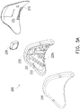
FIG. 5A is an exploded view of the second cushion module ofFIG. 4A . -
FIG. 5B is an exploded view of the second cushion module ofFIG. 4A from another perspective. -
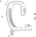
FIG. 6A is a perspective view of a third cushion module ofFIG. 1A . -
FIG. 6B is a perspective view of the third cushion module ofFIG. 6A from another perspective. -
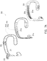
FIG. 7A is an exploded view of the third cushion module ofFIG. 6A . -
FIG. 7B is an exploded view of the third cushion module ofFIG. 6A from another perspective. -
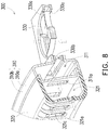
FIG. 8 is a partial cross-sectional view of the third cushion module ofFIG. 6A cut along an outlet of a third rear channel. -
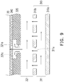
FIG. 9 is a schematic view of an airflow path of the third cushion module ofFIG. 6A . -
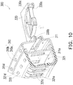
FIG. 10 is a partial cross-sectional view of a third cushion module according to another embodiment of the invention. -
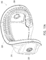
FIG. 11A is a perspective view of a third cushion module according to another embodiment of the invention. -
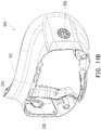
FIG. 11B is a perspective view of the third cushion module ofFIG. 11A from another perspective. -
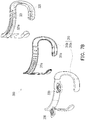
FIG. 12A is an exploded view of the third cushion module ofFIG. 11A . -
FIG. 12B is an exploded view of the third cushion module ofFIG. 11A from another perspective. -
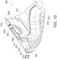
FIG. 13 is a partial cross-sectional view of the third cushion module ofFIG. 11A cut along the outlet of the third rear channel. - Referring to
FIGs. 1A and1B , in this embodiment, a head-mounteddisplay device 10 includes afront assembly 12 and awearable assembly 14. Thewearable assembly 14 is connected to thefront assembly 12 and is suitable for wearing thefront assembly 12 onto a face of a user. - In this embodiment, the
front assembly 12 may include an optical system (not shown), a protective housing, and other elements, and may be provided with a display or suitable for being provided with the display. The display may be a built-in display or an additional portable display (such as a smart phone, etc.), but the present application is not limited thereto. A type of the display may be adjusted according to an application of the head-mounteddisplay device 10 to a virtual reality system, an augmented reality system, or a mixed reality system. The optical system includes an optical member, such as a lens, a light guide member, or a prism, used to change an optical path of the display. In addition, thewearable assembly 14 may include any form of headband, and may also include any element or module used to adjust a length of the headband. - In order to cushion the pressure exerted by the
wearable assembly 14 on a head of the user, the head-mounteddisplay device 10 includes at least one of afirst cushion module 100, asecond cushion module 200, and athird cushion module 300. In this embodiment, thefirst cushion module 100 is used to abut against a frontal bone of the user. Thesecond cushion module 200 is used to abut against an occipital bone of the user. Thethird cushion module 300 is used to abut against a face of the user, particularly around eye sockets of the user. - Referring to
FIGs. 2A ,2B ,3A , and3B , thefirst cushion module 100 may include a firsthard member 110, a firstsoft member 120, and afirst fan 130. The firsthard member 110 is connected to the wearable assembly 14 (as shown inFIGs. 1A and1B ). The firstsoft member 120 is connected to the firsthard member 110 to contact skin of the user, and has a firstrear channel 121. Thefirst fan 130 communicates with the firstrear channel 121 to introduce external air into the firstrear channel 121. Thefirst fan 130 is, for example, an axial fan, but not limited thereto. - In this embodiment, a material of the first
hard member 110 is, for example, plastic or other materials that are not easily compressed, to provide support. The firsthard member 110 and a part of thewearable assembly 14 may be integrally formed. - In this embodiment, a material of the first
soft member 120 is, for example, rubber, silicone, foam, or other materials that are easily compressed, to provide cushioning. The firstsoft member 120 may have multiplefirst pillars 122. Thefirst pillars 122 may support the head of the user. The firstrear channel 121 extends between thefirst pillars 122. The firstsoft member 120 has one or more firstrear channel outlets 121a. The firstrear channel outlets 121a communicate with the firstrear channel 121 and are located on a surface of the firstsoft member 120 that does not contact the skin of the user. Since the airflow from thefirst fan 130 flows out of the firstrear channel outlets 121a through the first rear channel 121 (that is, through the first pillars 122), the user is less likely to feel stuffy in an area where the firstsoft member 120 contacts the skin. - In this embodiment, the
first cushion module 100 may further include afirst fabric layer 140. Thefirst fabric layer 140 covers the firstsoft member 120. Thefirst fabric layer 140 may adopt a breathable and cool cloth. Thefirst fabric layer 140 may cover the firstsoft member 120 in a detachable manner, to be removed for cleaning. In more detail, the airflow flowing in the firstrear channel 121 facilitates evaporation of the sweat absorbed by thefirst fabric layer 140 so as to lower the temperature. Therefore, the user is less likely to feel stuffy in an area where thefirst fabric layer 140 contacts the skin. - Referring to
FIGs. 4A ,4B ,5A , and5B , thesecond cushion module 200 may include a secondhard member 210, a secondsoft member 220, and asecond fan 230. The secondhard member 210 is connected to the wearable assembly 14 (as shown inFIGs. 1A and1B ). The secondsoft member 220 is connected to the secondhard member 210 to contact the skin of the user, and has a secondrear channel 221. Thesecond fan 230 communicates with the secondrear channel 221 to introduce the external air into the secondrear channel 221. Thesecond fan 230 is, for example, an axial fan, but not limited thereto. - In this embodiment, a material of the second
hard member 210 is, for example, plastic or other materials that are not easily compressed, to provide support. The secondhard member 210 and a part of thewearable assembly 14 may be integrally formed. - In this embodiment, a material of the second
soft member 220 is, for example, rubber, silicone, foam, or other materials that are easily compressed, to provide cushioning. The secondsoft member 220 may have multiplesecond pillars 222. Thesecond pillars 222 may support the head of the user. The secondrear channel 221 extends between thesecond pillars 222. The secondsoft member 220 has one or more secondrear channel outlets 221a. The secondrear channel outlets 221a communicate with the secondrear channel 221 and are located on a surface of the secondsoft member 220 that does not contact the skin of the user. Therefore, since the airflow of thesecond fan 230 flows out of the secondrear channel outlets 221a through the second rear channel 221 (that is, through the second pillars 222), the user is less likely to feel stuffy in an area where the secondsoft member 220 contacts the skin. - In this embodiment, the
second cushion module 200 may further include asecond fabric layer 240. Thesecond fabric layer 240 covers the secondsoft member 220. Thesecond fabric layer 240 may adopt a breathable and cool cloth. Thesecond fabric layer 240 may cover the secondsoft member 220 in a detachable manner, to be removed for cleaning. In more detail, the airflow flowing in the secondrear channel 221 facilitates evaporation of the sweat absorbed by thesecond fabric layer 240 so as to lower the temperature. Therefore, the user is less likely to feel stuffy in an area where thesecond fabric layer 240 contacts the skin. - Referring to
FIGs. 6A ,6B ,7A ,7B ,8 , and9 , in this embodiment, thethird cushion module 300 may include a thirdhard member 310, a thirdsoft member 320, and multiplethird fans 330. The thirdhard member 310 is connected to the wearable assembly 14 (as shown inFIGs. 1A and1B ). The thirdsoft member 320 is connected to the thirdhard member 310 to contact a skin 20 (as shown inFIG. 8 ) of the user, and has a thirdrear channel 321. Thethird fans 330 communicate with the thirdrear channel 321 to introduce the external air into the thirdrear channel 321. - In this embodiment, the third
hard member 310 has afront channel 311, and thethird fans 330 communicate with the thirdrear channel 321 through thefront channel 311. The thirdhard member 310 may include afront cover 310a and arear cover 310b, and thefront cover 310a and therear cover 310b are connected to each other to form thefront channel 311. The thirdhard member 310 has multiplefront channel outlets 311a to communicate thefront channel 311 with the thirdrear channel 321. Thethird fans 330 may be inserted into the front assembly 12 (as shown inFIGs. 1A and1B ) to inject the external air or the internal air of thefront assembly 12 into the thirdrear channel 321 through thefront channel 311. When the internal air of thefront assembly 12 is drawn out by thethird fan 330, the temperature inside thefront assembly 12 may also be lowered. - In this embodiment, the third
soft member 320 has one or more thirdrear channel outlets 321a. The thirdrear channel outlets 321a communicate with the thirdrear channel 321 and are located on a surface of the thirdsoft member 320 that contacts the skin of the user. The thirdsoft member 320 has one ormore trenches 321c on the surface of the thirdsoft member 320. One or more of the thirdrear channel outlets 321a are in thecorresponding trenches 321c, so that the airflow may flow out from the thirdrear channel outlets 321a through thetrenches 321c. Thetrenches 321c may be regarded as secondary channels. The thirdsoft member 320 may surround the eyes of the user from a position between eyebrows of the user and extend to cheeks of the user, to abut around the eye sockets of the user. In more detail, since the airflow flows out through thetrenches 321c, the user is less likely to feel stuffy in an area where the thirdsoft member 320 contacts the skin. - In this embodiment, the
third fans 330 havemultiple air inlets 330a and anair outlet 330b. Theair inlets 330a respectively communicate with a space enclosed by the front assembly 12 (shown inFIGs. 1A and1B ) and the face of the user and with an external environment, and theair outlet 330b communicates with the thirdrear channel 321. Therefore, thethird fans 330 may draw out the air in the space enclosed by the front assembly 12 (as shown inFIGs. 1A and1B ) and the face of the user and mix the air with air drawn in from the external environment, and then inject the air into the thirdrear channel 321 and discharge the air to the outside from the thirdrear channel outlets 321a. Therefore, humidity and temperature in the space enclosed by thefront assembly 12 and the face of the user may be further lowered, so that the user is less likely to feel stuffy. Since the air flows out through thetrenches 321c, the user is less likely to feel stuffy in an area where the thirdsoft member 320 contacts the skin. - In another embodiment, the
air inlets 330a may also simultaneously draw in the high-temperature air in thefront assembly 12 and the air in the external environment, and inject the air into the thirdrear channel 321. Therefore, the temperature inside thefront assembly 12 may also be lowered. Since the air flows out through thetrenches 321c, the user is less likely to feel stuffy in an area where the thirdsoft member 320 contacts the skin. - In this embodiment, the
third cushion module 300 may further include a third fabric layer 340 (as shown inFIG. 9 ). Thethird fabric layer 340 covers the thirdsoft member 320. Thethird fabric layer 340 may adopt a breathable and cool cloth. Thethird fabric layer 340 may cover the thirdsoft member 320 in a detachable manner, to be removed for cleaning. In more detail, the airflow flowing out through thetrenches 321c facilitates evaporation of the sweat absorbed by thethird fabric layer 340 so as to lower the temperature. Therefore, the user is less likely to feel stuffy in an area where thethird fabric layer 340 contacts the skin. - Referring to
FIG. 10 , compared with the embodiment ofFIG. 8 , in another embodiment, the third hard member 310 (such as thefront cover 310a of the third hard member 310) may have one or morelateral airflow outlets 311d, and thelateral airflow outlets 311d communicate with thefront channel 311. In addition, the thirdsoft member 320 may have one or more lateralrear channel outlets 321d, and the lateralrear channel outlets 321d communicate with the thirdrear channel 321. The airflow blown from thelateral airflow outlets 311d and the lateralrear channel outlets 321d may flow through an area, such as the forehead, of the face of the user that is not covered by the thirdsoft member 320, so the user may feel cooler. - Referring to
FIGs. 11A ,11B ,12A ,12B , andFIG. 13 , another embodiment illustrated therein is substantially the same as the embodiment ofFIG. 6A , and the differences between the two embodiments are as follows. First, in the embodiment ofFIG. 6A , thethird fans 330 are located above the eyes of the user, but in this embodiment, thethird fans 330 are respectively located corresponding to the two cheeks of the user, and the thirdhard member 310 has multiple fan covers 310c, which are fixed to thefront cover 310a to fix thethird fans 330. In another embodiment, the fan covers 310c may also be integrated into a single member. - In addition, in this embodiment, the third
soft member 320 has a thickenedportion 323, and the thickenedportion 323 is distributed along the thirdrear channel 321. Therefore, when the thirdsoft member 320 is squeezed or worn, the thickenedportion 323 ensures that the thirdrear channel 321 is not interrupted and remains unblocked as much as possible. - In addition, in this embodiment, the number of the third
rear channels 321 is two, and the number of the thickenedportions 323 is two. Each of the thirdrear channels 321 extends from the forehead of the user to the cheeks of the user, and each of the thickenedportions 323 is distributed on the outside of the corresponding thirdrear channel 321. The number of thethird fans 330 is two, and thethird fans 330 respectively communicate to the thirdrear channels 321. - The
third fans 330 havemultiple air inlets 330a and anair outlet 330b. Theair inlets 330a respectively communicate with the space enclosed by the front assembly 12 (as shown inFIGs. 1A and1B ) and the face of the user and with the external environment, and theair outlet 330b communicates with the thirdrear channel 321. Therefore, thethird fans 330 may draw out the air in the space enclosed by the front assembly 12 (as shown inFIGs. 1A and1B ) and the face of the user and mix the air with air drawn in from the external environment, and then inject the air into the thirdrear channel 321 and discharge the air to the outside from the thirdrear channel outlets 321a. Therefore, humidity and temperature in the space enclosed by thefront assembly 12 and the face of the user may be further lowered, so that the user is less likely to feel stuffy. Since the air flows out through thetrenches 321c, the user is less likely to feel stuffy in an area where the thirdsoft member 320 contacts the skin. - In this embodiment, the
third cushion module 300 may also include a third fabric layer (not shown). The third fabric layer covers the thirdsoft member 320. The third fabric layer may adopt a breathable and cool cloth. The third fabric layer may cover the thirdsoft member 320 in a detachable manner, to be removed for cleaning. In more detail, the airflow flowing out through thetrenches 321c facilitates evaporation of the sweat absorbed by the third fabric layer so as to lower the temperature. Therefore, the user is less likely to feel stuffy in an area where the third fabric layer contacts the skin. - Based on the above, the soft member of the cushion module of the head-mounted display device is connected to the hard member and used to contact the skin of the user, and the fan drives the airflow to flow through the rear channel of the soft member to provide a heat dissipation effect.
Claims (15)
- A head-mounted display device, comprising:a front assembly;a wearable assembly, connected to the front assembly, and adapted for wearing the front assembly onto a face of a user; anda cushion module, comprising:a hard member, connected to the wearable assembly;a soft member, connected to the hard member to contact skin of the user, and having a rear channel; anda fan, communicating with the rear channel.
- The head-mounted display device according to claim 1, wherein the hard member has a front channel, and the fan communicates with the rear channel through the front channel.
- The head-mounted display device according to claim 1, wherein the hard member has at least one front channel outlet, and the at least one front channel outlet communicates the front channel with the rear channel.
- The head-mounted display device according to claim 1, wherein the hard member comprises a front cover and a rear cover, and the front cover and the rear cover are connected to each other to form the front channel.
- The head-mounted display device according to claim 1, wherein the soft member has at least one rear channel outlet, and the at least one rear channel outlet communicates with the rear channel and located on a surface of the soft member, which contacts the skin of the user.
- The head-mounted display device according to claim 1, wherein the soft member has at least one trench on a surface of the soft member, and the at least one rear channel outlet is in the at least one trench.
- The head-mounted display device according to claim 1, wherein the soft member surrounds eyes of the user from a position between eyebrows of the user and extends to cheeks of the user.
- The head-mounted display device according to claim 1, wherein the fan has a plurality of air inlets and an air outlet, the air inlets respectively communicate with a space enclosed by the front assembly and the face of the user and with an external environment, and the air outlet communicates with the rear channel.
- The head-mounted display device according to claim 1, wherein the soft member has a thickened portion, and the thickened portion is distributed along the rear channel.
- The head-mounted display device according to claim 9, wherein a number of the rear channels is two, a number of the thickened portions is two, each of the rear channels extends from a forehead of the user to cheeks of the user, and each of the thickened portions is distributed on an outside of the corresponding rear channel.
- The head-mounted display device according to claim 10, wherein a number of the fans is two, and the fans respectively communicate to the rear channels.
- The head-mounted display device according to claim 1, wherein the soft member has a plurality of pillars to abut against a head of the user, and the rear channel extends between the pillars.
- The head-mounted display device according to claim 1, wherein the cushion module further comprises:
a fabric layer, covering the soft member. - The head-mounted display device according to claim 1, wherein the hard member has a front channel, the fan communicates with the rear channel through the front channel, the hard member has at least one lateral airflow outlet, and the at least one lateral airflow outlet communicates with the front channel.
- The head-mounted display device according to claim 1, wherein the soft member has at least one lateral rear channel outlet, and the at least one lateral rear channel outlet communicates with the rear channel.
Applications Claiming Priority (2)
| Application Number | Priority Date | Filing Date | Title |
|---|---|---|---|
| US202063036451P | 2020-06-09 | 2020-06-09 | |
| US17/143,173 US11737218B2 (en) | 2020-06-09 | 2021-01-07 | Head-mounted display device |
Publications (2)
| Publication Number | Publication Date |
|---|---|
| EP3923058A1 true EP3923058A1 (en) | 2021-12-15 |
| EP3923058B1 EP3923058B1 (en) | 2022-12-21 |
Family
ID=75825740
Family Applications (1)
| Application Number | Title | Priority Date | Filing Date |
|---|---|---|---|
| EP21172603.9A Active EP3923058B1 (en) | 2020-06-09 | 2021-05-06 | Head-mounted display device |
Country Status (2)
| Country | Link |
|---|---|
| US (1) | US11737218B2 (en) |
| EP (1) | EP3923058B1 (en) |
Families Citing this family (24)
| Publication number | Priority date | Publication date | Assignee | Title |
|---|---|---|---|---|
| US12138532B2 (en) | 2022-06-20 | 2024-11-12 | Htc Corporation | Head-mounted display device |
| US12422683B2 (en) * | 2022-09-20 | 2025-09-23 | Apple Inc. | Active cooling for head-mounted display |
| US12701212B2 (en) | 2023-05-15 | 2026-08-04 | Apple Inc. | Head mountable display |
| US12597219B2 (en) | 2023-05-15 | 2026-04-07 | Apple Inc. | Head mountable display |
| US12196974B2 (en) | 2023-05-15 | 2025-01-14 | Apple Inc. | Head mountable display |
| US12210169B2 (en) | 2023-05-15 | 2025-01-28 | Apple Inc. | Head mountable display |
| US12238909B2 (en) | 2023-05-15 | 2025-02-25 | Apple Inc. | Head mountable display |
| US12379595B2 (en) | 2023-05-15 | 2025-08-05 | Apple Inc. | Head mountable display |
| US12148332B1 (en) | 2023-05-15 | 2024-11-19 | Apple Inc. | Head mountable display |
| US12289874B2 (en) | 2023-05-15 | 2025-04-29 | Apple Inc. | Head mountable display |
| US12659568B2 (en) | 2023-05-15 | 2026-06-16 | Apple Inc. | Head mountable display |
| US12347051B2 (en) | 2023-05-15 | 2025-07-01 | Apple Inc. | Head mountable display |
| US12169283B2 (en) | 2023-05-15 | 2024-12-17 | Apple Inc. | Head mountable display |
| US12061339B1 (en) | 2023-05-15 | 2024-08-13 | Apple Inc. | Head mountable display |
| US12614483B2 (en) | 2023-05-15 | 2026-04-28 | Apple Inc. | Head mountable display |
| US12645292B2 (en) | 2023-05-15 | 2026-06-02 | Apple Inc. | Head mountable display |
| US20240389287A1 (en) * | 2023-05-15 | 2024-11-21 | Apple Inc. | Head mountable display ventilation |
| US12147598B1 (en) | 2023-05-15 | 2024-11-19 | Apple Inc. | Head mountable display |
| US12554323B2 (en) | 2023-05-15 | 2026-02-17 | Apple Inc. | Head mountable display |
| CN117310991B (en) * | 2023-10-08 | 2024-04-05 | 广州邦士度眼镜有限公司 | Folding multifunctional intelligent glasses |
| US12684106B2 (en) | 2024-01-08 | 2026-07-14 | Meta Platforms Technologies, Llc | Techniques for using floodlight LEDs when imaging sensors have an insufficient level of detail for identifying hand gestures, and mixed-reality systems and methods of using these techniques |
| CN221634295U (en) * | 2024-01-18 | 2024-08-30 | 深圳小宅科技有限公司 | Air conditioning device of VR head-mounted device |
| US20260086602A1 (en) * | 2024-09-20 | 2026-03-26 | Apple Inc. | Electronic device display curtain |
| CN224232046U (en) * | 2025-05-23 | 2026-05-12 | 深圳市优伴智慧科技有限公司 | VR head-mounted device |
Citations (3)
| Publication number | Priority date | Publication date | Assignee | Title |
|---|---|---|---|---|
| FR2944416A1 (en) * | 2009-04-17 | 2010-10-22 | Thales Sa | Helmet for pilot of aircraft e.g. weapon airplane or helicopter, has conduit permitting transmission of air flow from ventilation unit towards evacuation unit, where air flow cools evacuation unit by natural or forced thermal convection |
| WO2014082023A1 (en) * | 2012-11-23 | 2014-05-30 | Greenbaum Eric | Head mounted display |
| US20160255748A1 (en) * | 2015-02-27 | 2016-09-01 | Samsung Electronics Co., Ltd. | Electronic Device Having Heat Radiator and Method for Controlling the Electronic Device |
Family Cites Families (8)
| Publication number | Priority date | Publication date | Assignee | Title |
|---|---|---|---|---|
| US4825488A (en) | 1988-04-13 | 1989-05-02 | Bedford Peter H | Support pad for nonambulatory persons |
| US6409338B1 (en) * | 2000-09-25 | 2002-06-25 | Frank Saleem Jewell | Air-generating audible spectacles device |
| US9980416B2 (en) * | 2016-10-03 | 2018-05-22 | Grail Gear LLC | Electronic headset venting systems and methods |
| GB2559547A (en) * | 2017-02-02 | 2018-08-15 | Sony Interactive Entertainment Europe Ltd | Head-mounted apparatus and systems |
| US10379583B2 (en) | 2017-04-19 | 2019-08-13 | Facebook Technologies, Llc | System for discharging heat out of head-mounted display based on hybrid fan and heat pipe |
| US11042201B2 (en) * | 2018-10-08 | 2021-06-22 | Htc Corporation | Head-mounted display device |
| US11058026B1 (en) * | 2019-04-19 | 2021-07-06 | Apple Inc. | Air deflector for cooling system in a head-mounted device |
| US11860444B2 (en) * | 2020-04-15 | 2024-01-02 | Apple Inc. | Electronic devices with covering structures |
-
2021
- 2021-01-07 US US17/143,173 patent/US11737218B2/en active Active
- 2021-05-06 EP EP21172603.9A patent/EP3923058B1/en active Active
Patent Citations (3)
| Publication number | Priority date | Publication date | Assignee | Title |
|---|---|---|---|---|
| FR2944416A1 (en) * | 2009-04-17 | 2010-10-22 | Thales Sa | Helmet for pilot of aircraft e.g. weapon airplane or helicopter, has conduit permitting transmission of air flow from ventilation unit towards evacuation unit, where air flow cools evacuation unit by natural or forced thermal convection |
| WO2014082023A1 (en) * | 2012-11-23 | 2014-05-30 | Greenbaum Eric | Head mounted display |
| US20160255748A1 (en) * | 2015-02-27 | 2016-09-01 | Samsung Electronics Co., Ltd. | Electronic Device Having Heat Radiator and Method for Controlling the Electronic Device |
Also Published As
| Publication number | Publication date |
|---|---|
| US11737218B2 (en) | 2023-08-22 |
| EP3923058B1 (en) | 2022-12-21 |
| US20210385954A1 (en) | 2021-12-09 |
Similar Documents
| Publication | Publication Date | Title |
|---|---|---|
| US11737218B2 (en) | Head-mounted display device | |
| US10314213B2 (en) | Electronic headset venting systems and methods | |
| US12422683B2 (en) | Active cooling for head-mounted display | |
| US10905186B2 (en) | Head-mounted display device | |
| CN107577048B (en) | Focusing assembly of optical lens | |
| US6409338B1 (en) | Air-generating audible spectacles device | |
| WO2019000556A1 (en) | Head-mounted display apparatus | |
| EP3599770A1 (en) | Headphones | |
| CN206321884U (en) | A kind of facing device for helmet | |
| TW202024850A (en) | Headset display device | |
| CN114706218A (en) | Comfortable VR glasses of built-in massage structure | |
| CN113835226B (en) | Head-mounted display device | |
| CN110865455A (en) | Nose pad structure and headgear using the same | |
| CN210776036U (en) | Head-mounted display and face mask thereof | |
| US20230213768A1 (en) | Light-shielding member and head-mounted display | |
| CN108828775A (en) | One kind can radiate VR spectacle frame | |
| CN217279128U (en) | VR glasses | |
| CN110471184A (en) | A kind of virtual instruction glasses based on VR convenient for wearing | |
| TW202414028A (en) | Head-mounted display | |
| CN117631291A (en) | Electronic devices with sweat relief structures | |
| KR102061425B1 (en) | Head-mounted display Apparatus with enhanced view | |
| US12608058B2 (en) | Air conditioning device of VR head-mounted equipment | |
| CN221225177U (en) | Wear-type VR shows interactive device | |
| US20240100811A1 (en) | Cushion assembly for wearable devices | |
| CN220933275U (en) | VR equipment auxiliary wearing device |
Legal Events
| Date | Code | Title | Description |
|---|---|---|---|
| PUAI | Public reference made under article 153(3) epc to a published international application that has entered the european phase |
Free format text: ORIGINAL CODE: 0009012 |
|
| STAA | Information on the status of an ep patent application or granted ep patent |
Free format text: STATUS: EXAMINATION IS IN PROGRESS |
|
| 17P | Request for examination filed |
Effective date: 20210506 |
|
| AK | Designated contracting states |
Kind code of ref document: A1 Designated state(s): AL AT BE BG CH CY CZ DE DK EE ES FI FR GB GR HR HU IE IS IT LI LT LU LV MC MK MT NL NO PL PT RO RS SE SI SK SM TR |
|
| B565 | Issuance of search results under rule 164(2) epc |
Effective date: 20211029 |
|
| RBV | Designated contracting states (corrected) |
Designated state(s): AL AT BE BG CH CY CZ DE DK EE ES FI FR GB GR HR HU IE IS IT LI LT LU LV MC MK MT NL NO PL PT RO RS SE SI SK SM TR |
|
| GRAP | Despatch of communication of intention to grant a patent |
Free format text: ORIGINAL CODE: EPIDOSNIGR1 |
|
| STAA | Information on the status of an ep patent application or granted ep patent |
Free format text: STATUS: GRANT OF PATENT IS INTENDED |
|
| INTG | Intention to grant announced |
Effective date: 20220921 |
|
| GRAS | Grant fee paid |
Free format text: ORIGINAL CODE: EPIDOSNIGR3 |
|
| GRAA | (expected) grant |
Free format text: ORIGINAL CODE: 0009210 |
|
| STAA | Information on the status of an ep patent application or granted ep patent |
Free format text: STATUS: THE PATENT HAS BEEN GRANTED |
|
| AK | Designated contracting states |
Kind code of ref document: B1 Designated state(s): AL AT BE BG CH CY CZ DE DK EE ES FI FR GB GR HR HU IE IS IT LI LT LU LV MC MK MT NL NO PL PT RO RS SE SI SK SM TR |
|
| REG | Reference to a national code |
Ref country code: GB Ref legal event code: FG4D |
|
| REG | Reference to a national code |
Ref country code: DE Ref legal event code: R096 Ref document number: 602021001026 Country of ref document: DE |
|
| REG | Reference to a national code |
Ref country code: CH Ref legal event code: EP |
|
| REG | Reference to a national code |
Ref country code: AT Ref legal event code: REF Ref document number: 1539399 Country of ref document: AT Kind code of ref document: T Effective date: 20230115 |
|
| REG | Reference to a national code |
Ref country code: IE Ref legal event code: FG4D |
|
| REG | Reference to a national code |
Ref country code: NL Ref legal event code: FP |
|
| REG | Reference to a national code |
Ref country code: LT Ref legal event code: MG9D |
|
| PG25 | Lapsed in a contracting state [announced via postgrant information from national office to epo] |
Ref country code: SE Free format text: LAPSE BECAUSE OF FAILURE TO SUBMIT A TRANSLATION OF THE DESCRIPTION OR TO PAY THE FEE WITHIN THE PRESCRIBED TIME-LIMIT Effective date: 20221221 Ref country code: NO Free format text: LAPSE BECAUSE OF FAILURE TO SUBMIT A TRANSLATION OF THE DESCRIPTION OR TO PAY THE FEE WITHIN THE PRESCRIBED TIME-LIMIT Effective date: 20230321 Ref country code: LT Free format text: LAPSE BECAUSE OF FAILURE TO SUBMIT A TRANSLATION OF THE DESCRIPTION OR TO PAY THE FEE WITHIN THE PRESCRIBED TIME-LIMIT Effective date: 20221221 Ref country code: FI Free format text: LAPSE BECAUSE OF FAILURE TO SUBMIT A TRANSLATION OF THE DESCRIPTION OR TO PAY THE FEE WITHIN THE PRESCRIBED TIME-LIMIT Effective date: 20221221 |
|
| REG | Reference to a national code |
Ref country code: AT Ref legal event code: MK05 Ref document number: 1539399 Country of ref document: AT Kind code of ref document: T Effective date: 20221221 |
|
| PG25 | Lapsed in a contracting state [announced via postgrant information from national office to epo] |
Ref country code: RS Free format text: LAPSE BECAUSE OF FAILURE TO SUBMIT A TRANSLATION OF THE DESCRIPTION OR TO PAY THE FEE WITHIN THE PRESCRIBED TIME-LIMIT Effective date: 20221221 Ref country code: LV Free format text: LAPSE BECAUSE OF FAILURE TO SUBMIT A TRANSLATION OF THE DESCRIPTION OR TO PAY THE FEE WITHIN THE PRESCRIBED TIME-LIMIT Effective date: 20221221 Ref country code: HR Free format text: LAPSE BECAUSE OF FAILURE TO SUBMIT A TRANSLATION OF THE DESCRIPTION OR TO PAY THE FEE WITHIN THE PRESCRIBED TIME-LIMIT Effective date: 20221221 Ref country code: GR Free format text: LAPSE BECAUSE OF FAILURE TO SUBMIT A TRANSLATION OF THE DESCRIPTION OR TO PAY THE FEE WITHIN THE PRESCRIBED TIME-LIMIT Effective date: 20230322 |
|
| P01 | Opt-out of the competence of the unified patent court (upc) registered |
Effective date: 20230602 |
|
| PG25 | Lapsed in a contracting state [announced via postgrant information from national office to epo] |
Ref country code: SM Free format text: LAPSE BECAUSE OF FAILURE TO SUBMIT A TRANSLATION OF THE DESCRIPTION OR TO PAY THE FEE WITHIN THE PRESCRIBED TIME-LIMIT Effective date: 20221221 Ref country code: RO Free format text: LAPSE BECAUSE OF FAILURE TO SUBMIT A TRANSLATION OF THE DESCRIPTION OR TO PAY THE FEE WITHIN THE PRESCRIBED TIME-LIMIT Effective date: 20221221 Ref country code: PT Free format text: LAPSE BECAUSE OF FAILURE TO SUBMIT A TRANSLATION OF THE DESCRIPTION OR TO PAY THE FEE WITHIN THE PRESCRIBED TIME-LIMIT Effective date: 20230421 Ref country code: ES Free format text: LAPSE BECAUSE OF FAILURE TO SUBMIT A TRANSLATION OF THE DESCRIPTION OR TO PAY THE FEE WITHIN THE PRESCRIBED TIME-LIMIT Effective date: 20221221 Ref country code: EE Free format text: LAPSE BECAUSE OF FAILURE TO SUBMIT A TRANSLATION OF THE DESCRIPTION OR TO PAY THE FEE WITHIN THE PRESCRIBED TIME-LIMIT Effective date: 20221221 Ref country code: CZ Free format text: LAPSE BECAUSE OF FAILURE TO SUBMIT A TRANSLATION OF THE DESCRIPTION OR TO PAY THE FEE WITHIN THE PRESCRIBED TIME-LIMIT Effective date: 20221221 Ref country code: AT Free format text: LAPSE BECAUSE OF FAILURE TO SUBMIT A TRANSLATION OF THE DESCRIPTION OR TO PAY THE FEE WITHIN THE PRESCRIBED TIME-LIMIT Effective date: 20221221 |
|
| PG25 | Lapsed in a contracting state [announced via postgrant information from national office to epo] |
Ref country code: SK Free format text: LAPSE BECAUSE OF FAILURE TO SUBMIT A TRANSLATION OF THE DESCRIPTION OR TO PAY THE FEE WITHIN THE PRESCRIBED TIME-LIMIT Effective date: 20221221 Ref country code: PL Free format text: LAPSE BECAUSE OF FAILURE TO SUBMIT A TRANSLATION OF THE DESCRIPTION OR TO PAY THE FEE WITHIN THE PRESCRIBED TIME-LIMIT Effective date: 20221221 Ref country code: IS Free format text: LAPSE BECAUSE OF FAILURE TO SUBMIT A TRANSLATION OF THE DESCRIPTION OR TO PAY THE FEE WITHIN THE PRESCRIBED TIME-LIMIT Effective date: 20230421 Ref country code: AL Free format text: LAPSE BECAUSE OF FAILURE TO SUBMIT A TRANSLATION OF THE DESCRIPTION OR TO PAY THE FEE WITHIN THE PRESCRIBED TIME-LIMIT Effective date: 20221221 |
|
| REG | Reference to a national code |
Ref country code: DE Ref legal event code: R097 Ref document number: 602021001026 Country of ref document: DE |
|
| PLBE | No opposition filed within time limit |
Free format text: ORIGINAL CODE: 0009261 |
|
| STAA | Information on the status of an ep patent application or granted ep patent |
Free format text: STATUS: NO OPPOSITION FILED WITHIN TIME LIMIT |
|
| PG25 | Lapsed in a contracting state [announced via postgrant information from national office to epo] |
Ref country code: DK Free format text: LAPSE BECAUSE OF FAILURE TO SUBMIT A TRANSLATION OF THE DESCRIPTION OR TO PAY THE FEE WITHIN THE PRESCRIBED TIME-LIMIT Effective date: 20221221 |
|
| 26N | No opposition filed |
Effective date: 20230922 |
|
| PG25 | Lapsed in a contracting state [announced via postgrant information from national office to epo] |
Ref country code: MC Free format text: LAPSE BECAUSE OF FAILURE TO SUBMIT A TRANSLATION OF THE DESCRIPTION OR TO PAY THE FEE WITHIN THE PRESCRIBED TIME-LIMIT Effective date: 20221221 |
|
| REG | Reference to a national code |
Ref country code: BE Ref legal event code: MM Effective date: 20230531 |
|
| PG25 | Lapsed in a contracting state [announced via postgrant information from national office to epo] |
Ref country code: SI Free format text: LAPSE BECAUSE OF FAILURE TO SUBMIT A TRANSLATION OF THE DESCRIPTION OR TO PAY THE FEE WITHIN THE PRESCRIBED TIME-LIMIT Effective date: 20221221 Ref country code: MC Free format text: LAPSE BECAUSE OF FAILURE TO SUBMIT A TRANSLATION OF THE DESCRIPTION OR TO PAY THE FEE WITHIN THE PRESCRIBED TIME-LIMIT Effective date: 20221221 Ref country code: LU Free format text: LAPSE BECAUSE OF NON-PAYMENT OF DUE FEES Effective date: 20230506 |
|
| REG | Reference to a national code |
Ref country code: IE Ref legal event code: MM4A |
|
| PG25 | Lapsed in a contracting state [announced via postgrant information from national office to epo] |
Ref country code: IE Free format text: LAPSE BECAUSE OF NON-PAYMENT OF DUE FEES Effective date: 20230506 |
|
| PG25 | Lapsed in a contracting state [announced via postgrant information from national office to epo] |
Ref country code: IE Free format text: LAPSE BECAUSE OF NON-PAYMENT OF DUE FEES Effective date: 20230506 |
|
| PG25 | Lapsed in a contracting state [announced via postgrant information from national office to epo] |
Ref country code: IT Free format text: LAPSE BECAUSE OF FAILURE TO SUBMIT A TRANSLATION OF THE DESCRIPTION OR TO PAY THE FEE WITHIN THE PRESCRIBED TIME-LIMIT Effective date: 20221221 Ref country code: BE Free format text: LAPSE BECAUSE OF NON-PAYMENT OF DUE FEES Effective date: 20230531 |
|
| PG25 | Lapsed in a contracting state [announced via postgrant information from national office to epo] |
Ref country code: BG Free format text: LAPSE BECAUSE OF FAILURE TO SUBMIT A TRANSLATION OF THE DESCRIPTION OR TO PAY THE FEE WITHIN THE PRESCRIBED TIME-LIMIT Effective date: 20221221 |
|
| PG25 | Lapsed in a contracting state [announced via postgrant information from national office to epo] |
Ref country code: BG Free format text: LAPSE BECAUSE OF FAILURE TO SUBMIT A TRANSLATION OF THE DESCRIPTION OR TO PAY THE FEE WITHIN THE PRESCRIBED TIME-LIMIT Effective date: 20221221 |
|
| REG | Reference to a national code |
Ref country code: CH Ref legal event code: PL |
|
| PG25 | Lapsed in a contracting state [announced via postgrant information from national office to epo] |
Ref country code: CH Free format text: LAPSE BECAUSE OF NON-PAYMENT OF DUE FEES Effective date: 20240531 |
|
| PG25 | Lapsed in a contracting state [announced via postgrant information from national office to epo] |
Ref country code: CY Free format text: LAPSE BECAUSE OF FAILURE TO SUBMIT A TRANSLATION OF THE DESCRIPTION OR TO PAY THE FEE WITHIN THE PRESCRIBED TIME-LIMIT; INVALID AB INITIO Effective date: 20210506 |
|
| PG25 | Lapsed in a contracting state [announced via postgrant information from national office to epo] |
Ref country code: HU Free format text: LAPSE BECAUSE OF FAILURE TO SUBMIT A TRANSLATION OF THE DESCRIPTION OR TO PAY THE FEE WITHIN THE PRESCRIBED TIME-LIMIT; INVALID AB INITIO Effective date: 20210506 |
|
| PG25 | Lapsed in a contracting state [announced via postgrant information from national office to epo] |
Ref country code: TR Free format text: LAPSE BECAUSE OF FAILURE TO SUBMIT A TRANSLATION OF THE DESCRIPTION OR TO PAY THE FEE WITHIN THE PRESCRIBED TIME-LIMIT Effective date: 20221221 |
|
| PGFP | Annual fee paid to national office [announced via postgrant information from national office to epo] |
Ref country code: GB Payment date: 20260312 Year of fee payment: 6 |
|
| PGFP | Annual fee paid to national office [announced via postgrant information from national office to epo] |
Ref country code: NL Payment date: 20260317 Year of fee payment: 6 |
|
| PGFP | Annual fee paid to national office [announced via postgrant information from national office to epo] |
Ref country code: FR Payment date: 20260309 Year of fee payment: 6 |
|
| PG25 | Lapsed in a contracting state [announced via postgrant information from national office to epo] |
Ref country code: CH Free format text: THE PATENT HAS BEEN ANNULLED BY A DECISION OF A NATIONAL AUTHORITY Effective date: 20240531 |
|
| PGFP | Annual fee paid to national office [announced via postgrant information from national office to epo] |
Ref country code: DE Payment date: 20260310 Year of fee payment: 6 |
|
| PG25 | Lapsed in a contracting state [announced via postgrant information from national office to epo] |
Ref country code: MT Free format text: LAPSE BECAUSE OF NON-PAYMENT OF DUE FEES Effective date: 20230506 |