EP3923041A1 - Diffuser screen - Google Patents
Diffuser screen Download PDFInfo
- Publication number
- EP3923041A1 EP3923041A1 EP20275122.8A EP20275122A EP3923041A1 EP 3923041 A1 EP3923041 A1 EP 3923041A1 EP 20275122 A EP20275122 A EP 20275122A EP 3923041 A1 EP3923041 A1 EP 3923041A1
- Authority
- EP
- European Patent Office
- Prior art keywords
- face
- waveguides
- diffuser screen
- array
- waveguide
- Prior art date
- Legal status (The legal status is an assumption and is not a legal conclusion. Google has not performed a legal analysis and makes no representation as to the accuracy of the status listed.)
- Pending
Links
- 230000003287 optical effect Effects 0.000 claims abstract description 67
- 239000000758 substrate Substances 0.000 claims description 6
- 239000011521 glass Substances 0.000 claims description 5
- 239000004038 photonic crystal Substances 0.000 claims description 4
- 230000001419 dependent effect Effects 0.000 claims 1
- 230000004807 localization Effects 0.000 abstract description 21
- 238000012360 testing method Methods 0.000 description 38
- 239000000835 fiber Substances 0.000 description 26
- 239000000463 material Substances 0.000 description 6
- 239000003292 glue Substances 0.000 description 5
- 230000007423 decrease Effects 0.000 description 4
- 238000009792 diffusion process Methods 0.000 description 4
- 238000000034 method Methods 0.000 description 4
- 239000007787 solid Substances 0.000 description 3
- 230000008878 coupling Effects 0.000 description 2
- 238000010168 coupling process Methods 0.000 description 2
- 238000005859 coupling reaction Methods 0.000 description 2
- 238000005516 engineering process Methods 0.000 description 2
- NCGICGYLBXGBGN-UHFFFAOYSA-N 3-morpholin-4-yl-1-oxa-3-azonia-2-azanidacyclopent-3-en-5-imine;hydrochloride Chemical compound Cl.[N-]1OC(=N)C=[N+]1N1CCOCC1 NCGICGYLBXGBGN-UHFFFAOYSA-N 0.000 description 1
- 239000004593 Epoxy Substances 0.000 description 1
- 230000001154 acute effect Effects 0.000 description 1
- 230000009286 beneficial effect Effects 0.000 description 1
- 239000011248 coating agent Substances 0.000 description 1
- 238000000576 coating method Methods 0.000 description 1
- 235000012489 doughnuts Nutrition 0.000 description 1
- 230000000694 effects Effects 0.000 description 1
- 238000005286 illumination Methods 0.000 description 1
- 238000003384 imaging method Methods 0.000 description 1
- 238000002955 isolation Methods 0.000 description 1
- 239000013307 optical fiber Substances 0.000 description 1
- 238000005498 polishing Methods 0.000 description 1
- 238000000926 separation method Methods 0.000 description 1
- 239000002210 silicon-based material Substances 0.000 description 1
- 238000005245 sintering Methods 0.000 description 1
- 239000011343 solid material Substances 0.000 description 1
Images





Classifications
-
- G—PHYSICS
- G02—OPTICS
- G02B—OPTICAL ELEMENTS, SYSTEMS OR APPARATUS
- G02B6/00—Light guides; Structural details of arrangements comprising light guides and other optical elements, e.g. couplings
- G02B6/04—Light guides; Structural details of arrangements comprising light guides and other optical elements, e.g. couplings formed by bundles of fibres
- G02B6/06—Light guides; Structural details of arrangements comprising light guides and other optical elements, e.g. couplings formed by bundles of fibres the relative position of the fibres being the same at both ends, e.g. for transporting images
- G02B6/08—Light guides; Structural details of arrangements comprising light guides and other optical elements, e.g. couplings formed by bundles of fibres the relative position of the fibres being the same at both ends, e.g. for transporting images with fibre bundle in form of plate
-
- G—PHYSICS
- G02—OPTICS
- G02B—OPTICAL ELEMENTS, SYSTEMS OR APPARATUS
- G02B5/00—Optical elements other than lenses
- G02B5/02—Diffusing elements; Afocal elements
- G02B5/0205—Diffusing elements; Afocal elements characterised by the diffusing properties
-
- G—PHYSICS
- G02—OPTICS
- G02B—OPTICAL ELEMENTS, SYSTEMS OR APPARATUS
- G02B5/00—Optical elements other than lenses
- G02B5/02—Diffusing elements; Afocal elements
- G02B5/0273—Diffusing elements; Afocal elements characterized by the use
- G02B5/0278—Diffusing elements; Afocal elements characterized by the use used in transmission
Definitions
- Diffuser screens may be used in displays to scatter/diffuse light to more evenly distribute light.
- a fibre faceplate may be used as part of a screen to display an image to a user.
- a fibre faceplate transfers an image from an input face to an output face.
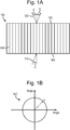
- An example of a fibre faceplate 100 is illustrated in Figure 1A .
- Fibre faceplate 100 comprises a plurality of waveguides 130 forming an optical path between a second face 105 and a first face 104.
- Each waveguide 130 may comprise an optical fibre of a sufficient size to allow at least a single mode of visible light to travel down the fibre without significant attenuation in the fibre by total internal reflection.
- the waveguides are multimode fibres, such that many modes are permitted in the fibres.
- Each waveguide 130 is also substantially similar to each other waveguide and substantially parallel to each other.
- Input light 110 may be input into the diffuser at an angle ⁇ to a normal of the first face 104.
- the input light propagates along an optical axis of the array of waveguides.
- Output light 120 is output in a cone of light about a normal to the second face 105.
- Figure 1B illustrates a projection 140 of the cone onto a plane that is perpendicular to the normal of the second face 105.
- the cone forms a ring of light, such that light input 110 in a straight line in a single direction is output in a cone of angle ⁇ .
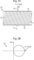
- FIG. 2A illustrates an angled fibre faceplate 200.
- Angled fibre faceplate 200 comprises a plurality of angled waveguides 230 forming an optical path between a first face 104 and a second face 105.
- the plurality of angled waveguides 230 are at an angle ⁇ with respect to a normal to the first face 104 or second face 105.
- Each angled waveguide 230 is also substantially similar to each other waveguide and substantially parallel to each other.
- Input light 110 may be input normal to the surface of the first face 104.
- Output light 120 is output in a cone of angle sin -1 (n sin 2 ⁇ ), where n is the refractive index of the waveguide.
- a consequence of the waveguides 230 not being perpendicular to the surface of the first face 104 is that the cone 120 is shifted relative to the case where the waveguides are perpendicular to the surface of the first face 104. This may allow for a display to be tilted or have an angular offset relative to the fibre face plate rather than directly in front of the second face 105.
- transverse Anderson localization may enable light to be emitted from the fibre in a solid cone, rather than a ring, and substantially independent of wavelength providing diffusion and removing the requirement for a separate diffuser screen. This is beneficial where even illumination may be desired over an appreciable cone angle.
- Transverse Anderson localization is described in " Transverse Anderson localization of light: a tutorial review, Arash Mafi, arXiv: 1505.01109v2 [physics.optics] 4 Jun 2015 ".
- Transverse Anderson localization may cause the absence of diffusion in the axis perpendicular to the optical axis of the waveguides in a system due to the presence of a disordered system.
- the optical axis is defined by the direction of propagation of light in the waveguide. In a conventional fibre waveguide the optical axis is the same as the longitudinal axis and the direction perpendicular is the transverse axis of the fibre waveguide.
- disorder may be added to the system by arranging waveguides having different optical properties such as randomly choosing the waveguide size from a set of different sizes of waveguide (e.g. width), or a set of different refractive indexes.
- the TAL diffuser screen 300 comprises a first face 304 and a second face 305 substantially parallel to the first face 304.
- Input light 310 is input into the TAL diffuser screen 300 via the first face 304, and output light 320 is emitted from second face 305.
- the TAL diffuser screen 300 comprises a plurality of waveguides 330 arranged in an array.
- the plurality of optical waveguides 330 form an optical path between the first face 304 and the second face 305.
- the optical axis of each of the plurality of waveguides 330 are arranged substantially perpendicular to the plane of the first face 304 and/or the first face 305.
- a value of an optical property of each of the waveguides in the array is selected at random from a set of values.
- the set of values may consist of two values, however any number of values may be appropriate.
- the value may be selected from a random continuous distribution of values or from predetermined discrete values.
- each individual waveguide is below the size that would allow a single optical mode to propagate along the waveguide if the waveguide was used in isolation.
- the output light 320 propagates through the TAL diffuser screen 300 without significant attenuation and is emitted in a roughly Gaussian distribution of angles around a direction substantially parallel with the direction of propagation in the waveguides (i.e the optical axis of the waveguides), as shown in Figure 3A and Figure 3B .
- the input angle is still nominally conserved, as with a fibre faceplate 100, however the output ray angles are effectively convolved with a Gaussian profile, to produce the profile as shown in Figure 3B .
- the output is a solid cone, however in some examples the output may be a donut shape depending on the width of the Gaussian profile or cone angle, as if the Gaussian profile is sufficiently wide or the cone angle sufficiently small then the middle may be filled.
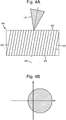
- Figure 4A illustrates an offset TAL diffuser screen 400.
- the arrangement of the offset TAL diffuser screen 400 is similar to the arrangement of the TAL diffuser screen 300 illustrated in Figure 3A , except that the optical axis of each of the plurality of waveguides are arranged at an angle 401 relative to a normal of one of the surfaces of first face 304 and second face 305, and similar features are illustrated with the same reference numeral.
- Input light 310 is input normal to the surface of the first face 304 of the offset diffuser screen 400.
- Light propagates through a plurality of offset waveguides 430 arranged in an array. The light is emitted substantially parallel with the optical axis of the offset waveguides as offset output light 420.
- Offset output light 420 like output light 320, is output with ray angles that are effectively convolved with a Gaussian profile, to produce the profile as shown in Figure 4B .
- the output profile may be a Gaussian distribution, or a Gaussian-like distribution such as a top-hat distribution or a super Gaussian distribution.
- the input cone angle may be ⁇ 3° and the output cone angle may be ⁇ 12°.
- the width of the Gaussian distribution may be increased by coupling two TAL diffuser screens together such that the output of one TAL diffuser screen is the input into another TAL diffuser screen.
- the TAL diffuser screens are similar to those described with relation to Figure 3A . Coupling two diffuser screens together results in a double TAL diffuser screen 500.
- the double TAL diffuser screen 500 is illustrated in Figure 5A .
- Double TAL diffuser screen 500 comprises two parts, a first part 500a and a second part 500b. Each first part 500a and second part 500b may be substantially similar to the TAL diffuser screen 300.
- the waveguides of the first part 500a and the second part 500b are positioned such that the outputs of the waveguides of the first part 500a do not align with the inputs of the waveguides of the second part 500b.
- First part 500a comprises a first face 504, a second face 505 substantially parallel to the first face 504.
- a plurality of waveguides 530a provide an optical path between the first face 504 and the second face 505 in an array.
- the plurality of waveguides may be substantially orthogonal to the first face 504.
- a value of an optical property of each of the waveguides 530a is selected randomly from a set of values.
- the set of values may consist of two values, however any number of values may be appropriate.
- the value may be selected from a random continuous distribution of values or from discrete predefined values or from predetermined discrete values.
- the size of each individual waveguide of the plurality of waveguides 530a is below the size that would allow a single optical mode to propagate along the waveguide.
- Second part 500b is optically coupled to the first part 500a such that the output from second face 505 is input into third face 506, and as stated above the individual inputs and outputs of the waveguides of the first part 500a and the second part 500b do not align.
- Second part 500b comprises third face 506, a fourth face 507 substantially parallel to the third face 506.
- a plurality of waveguides 530b are provide an optical path between the third face 506 and the fourth face 507.
- the waveguides are substantially orthogonal to the third face 506.
- the second face 505 and the third face 506 may be positioned as close to each other as practical depending upon the desired resolution of the image, as the obtainable resolution decreases with increasing separation.
- a value of an optical property of each of the waveguides 530b is selected randomly from a set of values.
- the set of values may consist of two values, however any number of values may be appropriate.
- the value may be selected from a random continuous distribution of values or from predetermined discrete values.
- the size of each individual waveguide of the plurality of waveguides 530b is below the size that would allow a single optical mode to propagate along the waveguide.
- the set of values may be identical for the first part 500a and the second part 500b. However, in some examples the set of values may be different, or the chance of selecting each of the set may be different. In some examples the size of each waveguide of the first part 500a and the second part 500b may be substantially the same, or may be different. The differences may be chosen based on the width of the Gaussian distribution required.
- the output light 520 is output in a Gaussian or Gaussian-like distribution of angles, as illustrated in Figure 5B , centred around a direction substantially parallel with the optical axis of the waveguides.
- the distribution may be a top-hat function or a super Gaussian function. This may be useful for some applications as it may result in a relatively constant luminance over part of the screen.
- the input cone angle may be ⁇ 3° and the output cone angle may be ⁇ 23°.
- the gap between the first part 500a and the second part 500b may be kept as small as practical.
- a constraint on the size of the gap may be the size of the image pixels or minimum desired feature size, as an increase in the size of the gap causes a decrease in the available resolution. As an example, if the pixel size is 4 ⁇ m then the gap should also be less than 4 ⁇ m.
- the gap may be an air gap.
- the gap may be filled with a bonding material, such as glue.
- the gap may be filled with an index-matched material.
- Figure 6 illustrates a straight-angled TAL diffuser screen 600 in accordance with some examples.
- the straight-angled TAL diffuser screen 600 is substantially similar to the double TAL diffuser screen 500, however one of the parts comprises waveguides with optical axes that are not orthogonal to one of the faces.
- the straight-angled TAL diffuser screen 600 comprises a straight part 600a and an angled part 600b. Similar to the double TAL diffuser screen 500 the individual outputs of the waveguides in the straight part 600a do not align with the inputs of the waveguides of the angled part 600b.
- the straight part 600a may be substantially similar to the diffusion 300 screen described in relation to Figure 3 .
- Straight part 600a comprises a first face 604, a second face 605 substantially parallel to the first face 604.
- a plurality of waveguides 630a are arranged in an array and provide an optical path between the first face 604 and the second face 605.
- the optical axis of each waveguide is substantially orthogonal to the first face 604.
- a value of an optical property of each of the waveguides 630a is selected randomly from a set of values.
- the set of values may consist of two values, however any number of values may be appropriate.
- the value may be selected from a random continuous distribution of values or from predetermined discrete values.
- each individual waveguide of the plurality of waveguides 630a is below the size that would conventionally allow a single optical mode to propagate along the waveguide without attenuation.
- Angled part 600b is optically coupled to the straight part 600a such that light that is output from second face 605 is coupled into third face 606, and such that the outputs of the waveguides of the second face 605 do not align with the inputs of the waveguides of the third face 606.
- Angled part 600b comprises a third face 606, a fourth face 607 substantially parallel to the third face 606.
- a plurality of waveguides 630b arranged in an array provide an optical path between the third face 606 and the fourth face 607.
- the plurality of waveguides 630b are arranged such that the optical axis of the waveguides 630b is at an angle 601 relative to a normal of the plane of the third face 606 and/or fourth face 607.
- a value of an optical property of each of the waveguides 630b is selected randomly from a set of values.
- the set of values may consist of two values, however any number of values may be appropriate.
- the value may be selected from a random continuous distribution of values or from predetermined discrete values.
- the size of each individual waveguide of the plurality of waveguides 630b is below the size that would allow a single optical mode to propagate along the waveguide.
- the set of values may be identical for the straight part 600a and the angled part 600b. However, in some examples the set of values may be different, or the chance of selecting each of the set may be different. In some examples the size of each waveguide of the straight part 600a and the angled part 600b may be substantially the same, or may be different. The differences may be chosen based on the width of the Gaussian-like distribution required.
- Light is input into straight-angled TAL diffuser screen 600 as input light 310 to the first face 604 of the straight part 600a.
- Light propagates along the straight part 600a in a similar manner to that described with relation to the TAL diffuser screen 300 of Figure 3A .
- the light then enters the angled part 600b through third face 606 and propagates along the plurality of waveguides 630b.
- the light is then output in a Gaussian or Gaussian-like distribution of angles around a direction that is parallel to the direction of the waveguides 630b.
- the Gaussian-like distribution may be a top hat distribution or a super Gaussian distribution.
- the angle 601 may be an acute angle.
- the angle may be chosen based on the offset of the Gaussian or Gaussian-like distribution that is desired, where a larger angle leads to a larger offset.
- a factor to consider when choosing the angle, similar to fibre faceplates, is that the output cone is changed relative to the optical axis of the waveguides based on an index change from the waveguide to air (or other medium that the light travels through).
- the gap between the straight part 600a and the angled part 600b may be kept as small as practical.
- a constraint on the size of the gap may be the size of the image pixels or minimum desired feature size, as an increase in the size of the gap causes a decrease in the available resolution. As an example, if the pixel size is 4 ⁇ m then the gap should also be less than 4 ⁇ m.
- the gap may be an air gap.
- the gap may be filled with a bonding material, such as glue.
- the gap may be filled with an index-matched material.
- Figure 7A illustrates an angled-straight TAL diffuser screen 700, which is a variation of the arrangements of Figures 5A and 6A .
- Angled-straight TAL diffuser screen 700 comprises an angled part 700a and a straight part 700b. Similar to arrangements of Figures 5A and 6A the outputs of the waveguides of the angled part 700a do not align with the inputs of the waveguides of the straight part 700b.
- Angled part 700a comprises a first face 704 and a second face 705.
- a plurality of waveguides 730a arranged in an array provide an optical path between the first face 704 and the second face 705.
- the plurality of waveguides have an optical axis that is at an angle 701 to a normal of the plane of the first face 704 and/or second face 705.
- a value of an optical property of each of the waveguides 730a is selected randomly from a set of values.
- the set of values may consist of two values, however any number of values may be appropriate.
- the value may be selected from a random continuous distribution of values or from predetermined discrete values.
- each individual waveguide of the plurality of waveguides 730a is below the size that would allow a single optical mode to propagate along the waveguide.
- Straight part 700b comprises a third face 706 and a third face 707.
- a plurality of waveguides 730b are located in an optical path between the third face 706 and the fourth face 707.
- the plurality of waveguides 730b are substantially orthogonal to the third face 706 and/or fourth face 707.
- a value of an optical property of each of the waveguides 730b is selected randomly from a set of values.
- the set of values may consist of two values, however any number of values may be appropriate.
- the value may be selected from a random continuous distribution of values or from predetermined discrete values.
- each individual waveguide of the plurality of waveguides 730b is below the size that would allow a single optical mode to propagate along the waveguide.
- Straight part 700b is optically coupled to angled part 700a, such that light may propagate between the angled part 700a and the straight part 700b.
- Light is input as input light 310 into angled part 700a via the first face 704.
- the light propagates along the plurality of waveguides 730a and output into the straight part 700b.
- the light propagates through angled part 700a in a similar manner to that of offset diffuser screen 400 described with relation to Figure 4 .
- the light is output with in a range of angles, the range having a Gaussian profile, around a direction parallel with the optical axis of the waveguides 730a.
- the output light is then input into straight part 700b.
- the straight part 700b also behaves like the TAL diffuser screen 300 described in relation to Figure 3 .
- the width of the Gaussian or Gaussian-like profile may be increased.
- the example profile is illustrated in Figure 7B , which shows that the profile is symmetrical with no offset, in contrast with the arrangement of Figure 6A .
- the Gaussian-like profile may comprise a top hat distribution or a super Gaussian distribution.
- the gap between the angled part 700a and the straight part 700b may be kept as small as practical.
- a constraint on the size of the gap may be the size of the image pixels or minimum desired feature size, as an increase in the size of the gap causes a decrease in the available resolution. As an example, if the pixel size is 4 ⁇ m then the gap should also be less than 4 ⁇ m.
- the gap may be an air gap.
- the gap may be filled with a bonding material, such as glue.
- the gap may be filled with an index-matched material.
- Figures 3-7 show TAL diffuser screens with a plurality of waveguides substantially parallel to each other and substantially straight, i.e. the optical axis is substantially parallel.
- the waveguides may have an optical axis that is substantially parallel to their nearest neighbours, but not parallel to every waveguide in the TAL diffuser screen.
- the waveguides are also not required to be straight or substantially straight.
- a first waveguide may be perpendicular to the first face, and the angle relative to a normal of the first face may increase with distance from the first waveguide.
- the angle may stay constant in one dimension in the plane of the first face, or may vary in two dimensions in the plane of the first face. In some examples the angle may also vary in the dimension along the waveguide, such that the waveguides are curved.
- the waveguides may have the same curvature, or the curvature may vary by waveguide.
- Figure 8 illustrates a variable offset TAL diffuser screen 800 where not all the waveguides are parallel to each other.
- a result of such a structure is that the cone angle offset varies with position, such that there is substantially no offset in the centre 801 of the variable offset TAL diffuser screen 800 and an increasing offset outside of the centre 801.
- Figures 3-7 show the input light as a single straight ray.
- the input light may be input in a range of angles, for example ⁇ 3°.
- the light input may be input as an image over a finite area of the TAL diffuser screen, i.e. a supposition of single rays.
- the output would be a supposition of cones, conserving or increasing the size of the image that is output compared to the input image.
- FIGS 5-7 illustrate 2 TAL diffuser screens being stacked, however, any number of screens in any arrangement may be stacked, depending upon the required characteristics.
- the TAL diffuser screen may be bonded to a glass substrate.
- the faces of the TAL diffuser screens are shown as being substantially straight, however in some examples the at least one of the faces may be curved.
- the array of waveguides described in relation to Figures 3A-7B may comprise a photonic crystal structure, such that each waveguide comprises a hole in a lattice structure.
- the holes may be filled with air.
- the holes may be filled with a solid material, such as a plastic or silicon based material.
- the overall thickness of the diffuser screen according to some examples, such as those described in reference to Figures 3-8 may depend upon the specific application and size of waveguide, where are larger waveguide may require a thicker screen.
- the diffuser screen thickness may be between 0.25 mm and 1.5 mm. In some examples the diffuser screen thickness may be between 0.5 mm and 1 mm.
- Figure 9 illustrates a method to fabricate a TAL fibre diffuser screen according to some examples. The method is indicated with reference sign 900.
- the method begins at start 910.
- a waveguide is chosen at random from a set of waveguides 920.
- the set of waveguides comprises a first subset comprising a plurality of waveguides having a first value of an optical property and a second subset comprising a plurality of waveguides having a second value of the optical property, the first value and second value being different. There may any number of subsets each comprising a different value of the optical property.
- Selection of the waveguides is repeated n times 930 in total, such that there are n waveguides chosen, each waveguide having a value of the optical property that is one of a predetermined number of values.
- the waveguides are then bonded or fused together 840. In some examples this may comprise sintering and drawing out the waveguides. Some of the waveguides will melt, and some will stay complete, further adding to the randomness of the screen.
- the optical faces of the diffuser screens are prepared 850. In some examples this may comprise polishing the faces such that they are optically smooth.
- the output or input faces of the waveguides may be at least substantially curved as appropriate for the optics to which it is attached. By using non-flat surfaces field flatness of imaging optics may be cured or mitigated.
- a diffuser screen utilising transverse Anderson localization was fabricated, the diffuser screen herein referred to as the test screen.
- the test screen comprised two 24 mm diameter, 0.5 mm thick, Nanoguide faceplates, manufactured by Incom, 294 Southbridge Road, Charlton, MA 01507.
- the faceplates were bonded together using EPO-TEK 301-LP glue, EPO-TEK 301-LP is a glue made by Epoxy Technology, Inc., 14 Fortune Drive, Billerica, MA 01821.
- the bonded Nanoguide screens were bonded to a 1 mm thick glass substrate, the glass substrate comprising an anti-reflection coating on one side.
- Both Incom Nanoguide screens comprised waveguides having an optical axis perpendicular to the substrate surface.
- the final diameter of the test screen was less than 25 mm.
- test screen was compared to a reference screen, which was a high resolution screen used on helmet mounted displays based on diffractive technology similar to that described with relation to Figures 1 and 2 and a separate diffuser.
- Figures 10A-10C illustrate comparisons of cone angles for the test screen and reference screen for red, green and blue light.
- Figure 10A illustrates the cone angle for green light of both the test and reference screen.
- Figure 9B illustrates the cone angle for red light of both the test and reference screen.
- Figure 9C illustrates the cone angle for blue light of both the test and reference screen.
- test screen is either similar to the conventional screen (red and green light) or better (blue light) but without any of the peaks and troughs.
- test diffuser screen gives an approximately Gaussian profile with a very similar linewidth for each colour.
- the intensities are different as each light source used in the testing has a different input power, and therefore the measured output power is different.
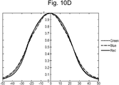
- Figure 10D illustrates a plot of cone angles for green, blue and red light against normalised power for the test screen. This demonstrates that the profiles are indeed very similar. As the RGB cone angles are virtually identical there should be no varying colour balance issues across the field of view or eyebox.
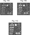
- Figure 11A shows a resolution test of the reference screen for green light.
- Figure 10B shows a resolution test for the test screen using green light.
- Figure 10C shows a resolution test for the test screen for red light.
- the resolution ranges from 6,6 to 7,1 over the area of the reference screen. However, for the same colour in Figure 11B the resolution ranges from 7,4 to 7,6 over the area of the test screen. For the test screen using red light, the resolution is 7,3. Overall, for the diffuser screen using transverse Anderson localization the resolution is better than 181 cy/mm for the green and blue light, and 161 cy/mm for red light.
- a 5 mm x 5 mm second test screen was fabricated using a Nanoguide faceplate.
- the waveguides of the screen were substantially perpendicular to the face of the screen, and the faceplate was substantially flat (i.e. substantially similar to Figure 3A ).
- the second test screen was compared to a standard screen used in many HUD applications (second reference screen) comprising a fibre faceplate and a separate diffusion screen. Green light was input at a ⁇ 3° input angle to both the second test screen and second reference screen.
- Figure 12A shows the variation intensity across various cone angles for the second reference screen and Figure 12B shows the cone angle masked for an application of a HUD.
- Figure 12C shows the variation intensity across various cone angles for the second test screen and Figure 12D shows the cone angle masked for an application of a HUD.
- Figures 12B and 12D indicate the position of the cone angle plots in Figures 12E and 12F.
- Figure 12E shows the horizontal cone angle plotted against intensity
- Figure 11F shows the vertical cone angle plotted against intensity.
- the second test screen is approximately 20% brighter at centre of used cone.
- the second test screen also was demonstrated to have a 128 cy/mm resolution using a USAF pattern projected through the second test screen. This is in comparison with the second reference screen which has a resolution of 57 cy/mm.
- the granularity of the second test screen and second reference screen were measured by analysing a high resolution image of an evenly illuminated screen.
- Figure 13A shows the granularity of a 0.2 mm x 0.2 mm section of the image displayed by the reference screen.
- Figure 13B shows the granularity of a 0.2 mm x 0.2 mm section of the image displayed by the test screen.
- Figure 13C shows a plot of the rate of change of greyscale standard deviation against image pixel size for the second reference screen and the second test screen.
- the image pixel size is changed by re-scaling the image resolution to that indicated on the horizontal axis of Figure 13C .
- the first point on the graph is at 3 ⁇ m, i.e. the start image resolution pixel size was 3 ⁇ m.
- the last point is at 23 ⁇ m so the end picture resolution pixel size was increased to 23 ⁇ m.
Landscapes
- Physics & Mathematics (AREA)
- General Physics & Mathematics (AREA)
- Optics & Photonics (AREA)
- Overhead Projectors And Projection Screens (AREA)
Abstract
A diffuser screen for visible light utilizing transverse Anderson localization is disclosed. The diffuser screen comprises a first part comprising: a first face and second face substantially parallel to each other, a first array of a plurality of waveguides forming an optical path between the first face and the second face. A value of an optical property of each of the plurality of waveguides is selected randomly from a set of values of the optical property. The first array of a plurality of waveguides is arranged such that each of the plurality of waveguides has an optical axis that is substantially parallel to its nearest neighbour. Substantially all the waveguides of the first array are sized below a size that would allow a single mode of visible light to propagate along each waveguide
Description
- Diffuser screens may be used in displays to scatter/diffuse light to more evenly distribute light.
-
-
Figure 1A is an illustration of a fibre faceplate. -
Figure 1B illustrates an output cone angle from the fibre faceplate. -
Figure 2A is an illustration of an angled fibre faceplate. -
Figure 2B illustrates an output cone angle from an angled fibre faceplate. -
Figure 3A illustrates a transverse Anderson localisation diffuser screen in accordance with some examples. -
Figure 3B illustrates an output cone angle from a transverse Anderson localisation angled diffuser screen. -
Figure 4A illustrates an angled transverse Anderson localisation diffuser screen in accordance with some examples. -
Figure 4B illustrates an output cone angle from an angled transverse Anderson localisation angled diffuser screen. -
Figure 5A illustrates a double transverse Anderson localisation diffuser screen in accordance with some examples. -
Figure 5B illustrates an output cone angle from a double transverse Anderson localisation angled diffuser screen. -
Figure 6A illustrates a straight-angled transverse Anderson localisation diffuser screen in accordance with some examples. -
Figure 6B illustrates an output cone angle from a straight-angled transverse Anderson localisation angled diffuser screen. -
Figure 7A illustrates an angled-straight transverse Anderson localisation diffuser screen in accordance with some examples. -
Figure 7B illustrates an output cone angle from an angled-straight transverse Anderson localisation angled diffuser screen. -
Figure 8 illustrates a variable offset transverse Anderson localisation diffuser screen according to some examples. -
Figure 9 illustrates a method to fabricate a transverse Anderson localisation fibre diffuser screen according to some examples. -
Figures 10A-10C illustrate power against angle of emission for green, red and blue light for both a reference and test screen. -
Figure 10D illustrates a plot of cone angles for green, blue and red light against normalised power for a test screen. -
Figure 11A shows a resolution test of the reference screen for green light. -
Figure 11B shows a resolution test for the test screen using green light. -
Figure 11C shows a resolution test for the test screen for red light. -
Figure 12A shows the variation intensity across various cone angles for the second reference screen. -
Figure 12B shows the cone angle masked for an application of a head up display. -
Figure 12C shows the variation intensity across various cone angles for the second test screen. -
Figure 12D shows the cone angle masked for an application of a head mounted display. -
Figures 13A-C illustrate the granularity of the second test and second reference screen. - In some applications, such as a head up display, a fibre faceplate may be used as part of a screen to display an image to a user. A fibre faceplate transfers an image from an input face to an output face. An example of a
fibre faceplate 100 is illustrated inFigure 1A .Fibre faceplate 100 comprises a plurality ofwaveguides 130 forming an optical path between asecond face 105 and afirst face 104. Eachwaveguide 130 may comprise an optical fibre of a sufficient size to allow at least a single mode of visible light to travel down the fibre without significant attenuation in the fibre by total internal reflection. In most examples the waveguides are multimode fibres, such that many modes are permitted in the fibres. Eachwaveguide 130 is also substantially similar to each other waveguide and substantially parallel to each other. -
Input light 110 may be input into the diffuser at an angle α to a normal of thefirst face 104. The input light propagates along an optical axis of the array of waveguides.Output light 120 is output in a cone of light about a normal to thesecond face 105. -
Figure 1B illustrates aprojection 140 of the cone onto a plane that is perpendicular to the normal of thesecond face 105. As can be seen inFigure 1B , the cone forms a ring of light, such thatlight input 110 in a straight line in a single direction is output in a cone of angle α. -
Figure 2A illustrates anangled fibre faceplate 200.Angled fibre faceplate 200 comprises a plurality ofangled waveguides 230 forming an optical path between afirst face 104 and asecond face 105. The plurality ofangled waveguides 230 are at an angle β with respect to a normal to thefirst face 104 orsecond face 105. Eachangled waveguide 230 is also substantially similar to each other waveguide and substantially parallel to each other. -
Input light 110 may be input normal to the surface of thefirst face 104.Output light 120 is output in a cone of angle sin-1 (n sin 2β), where n is the refractive index of the waveguide. - As illustrated by
Figure 2B , a consequence of thewaveguides 230 not being perpendicular to the surface of thefirst face 104 is that thecone 120 is shifted relative to the case where the waveguides are perpendicular to the surface of thefirst face 104. This may allow for a display to be tilted or have an angular offset relative to the fibre face plate rather than directly in front of thesecond face 105. - However, in both examples of
Figures 1A and2A light is emitted in a cone around a central axis. In some situations it may be desirable to have the light emitted in a solid cone, rather than a ring. If a fibre faceplate is used then a separate diffuser may be used to diffuse the image over the entire cone angle. Otherwise the image displayed to the user would be patchy, as a consequence of the light being emitted in a cone of light is that not all parts of the screen would be illuminated or would be illuminated non-uniformly. This also may reduce the quality of the image displayed to the user or extra elements may be required to mitigate this effect. - In this disclosure it has been identified that a fibre face plate screen utilising transverse Anderson localization may enable light to be emitted from the fibre in a solid cone, rather than a ring, and substantially independent of wavelength providing diffusion and removing the requirement for a separate diffuser screen. This is beneficial where even illumination may be desired over an appreciable cone angle. Transverse Anderson localization is described in "Transverse Anderson localization of light: a tutorial review, Arash Mafi, arXiv: 1505.01109v2 [physics.optics] 4 Jun 2015".
- The use of a fibre faceplate utilising transverse Anderson localization may lead to a more uniform image and allow a user to see a higher quality image without the use of a separate fibre face plate. Transverse Anderson localization may cause the absence of diffusion in the axis perpendicular to the optical axis of the waveguides in a system due to the presence of a disordered system. The optical axis is defined by the direction of propagation of light in the waveguide. In a conventional fibre waveguide the optical axis is the same as the longitudinal axis and the direction perpendicular is the transverse axis of the fibre waveguide.
- In the example of a fibre faceplate, disorder may be added to the system by arranging waveguides having different optical properties such as randomly choosing the waveguide size from a set of different sizes of waveguide (e.g. width), or a set of different refractive indexes.
- An example of a transverse Anderson localization (TAL)
diffuser screen 300 according to some examples is illustrated inFigure 3A . TheTAL diffuser screen 300 comprises afirst face 304 and asecond face 305 substantially parallel to thefirst face 304.Input light 310 is input into theTAL diffuser screen 300 via thefirst face 304, andoutput light 320 is emitted fromsecond face 305. - The
TAL diffuser screen 300 comprises a plurality ofwaveguides 330 arranged in an array. The plurality ofoptical waveguides 330 form an optical path between thefirst face 304 and thesecond face 305. The optical axis of each of the plurality ofwaveguides 330 are arranged substantially perpendicular to the plane of thefirst face 304 and/or thefirst face 305. A value of an optical property of each of the waveguides in the array is selected at random from a set of values. In some examples the set of values may consist of two values, however any number of values may be appropriate. In some examples the value may be selected from a random continuous distribution of values or from predetermined discrete values. - The size of each individual waveguide is below the size that would allow a single optical mode to propagate along the waveguide if the waveguide was used in isolation. However, due to the structure of the
TAL diffuser screen 300 and the disorder added by randomly choosing an optical property of each waveguide, theoutput light 320 propagates through theTAL diffuser screen 300 without significant attenuation and is emitted in a roughly Gaussian distribution of angles around a direction substantially parallel with the direction of propagation in the waveguides (i.e the optical axis of the waveguides), as shown inFigure 3A and Figure 3B . - The input angle is still nominally conserved, as with a
fibre faceplate 100, however the output ray angles are effectively convolved with a Gaussian profile, to produce the profile as shown inFigure 3B . As can be seen fromFigure 3B the output is a solid cone, however in some examples the output may be a donut shape depending on the width of the Gaussian profile or cone angle, as if the Gaussian profile is sufficiently wide or the cone angle sufficiently small then the middle may be filled. -
Figure 4A illustrates an offsetTAL diffuser screen 400. The arrangement of the offsetTAL diffuser screen 400 is similar to the arrangement of theTAL diffuser screen 300 illustrated inFigure 3A , except that the optical axis of each of the plurality of waveguides are arranged at anangle 401 relative to a normal of one of the surfaces offirst face 304 andsecond face 305, and similar features are illustrated with the same reference numeral. -
Input light 310 is input normal to the surface of thefirst face 304 of the offsetdiffuser screen 400. Light propagates through a plurality of offsetwaveguides 430 arranged in an array. The light is emitted substantially parallel with the optical axis of the offset waveguides as offsetoutput light 420. Offsetoutput light 420, likeoutput light 320, is output with ray angles that are effectively convolved with a Gaussian profile, to produce the profile as shown inFigure 4B . the output profile may be a Gaussian distribution, or a Gaussian-like distribution such as a top-hat distribution or a super Gaussian distribution. - In some examples the input cone angle may be ±3° and the output cone angle may be ±12°.
- The width of the Gaussian distribution may be increased by coupling two TAL diffuser screens together such that the output of one TAL diffuser screen is the input into another TAL diffuser screen. The TAL diffuser screens are similar to those described with relation to
Figure 3A . Coupling two diffuser screens together results in a doubleTAL diffuser screen 500. The doubleTAL diffuser screen 500 is illustrated inFigure 5A . - Double
TAL diffuser screen 500 comprises two parts, afirst part 500a and asecond part 500b. Eachfirst part 500a andsecond part 500b may be substantially similar to theTAL diffuser screen 300. The waveguides of thefirst part 500a and thesecond part 500b are positioned such that the outputs of the waveguides of thefirst part 500a do not align with the inputs of the waveguides of thesecond part 500b. -
First part 500a comprises afirst face 504, asecond face 505 substantially parallel to thefirst face 504. A plurality ofwaveguides 530a provide an optical path between thefirst face 504 and thesecond face 505 in an array. The plurality of waveguides may be substantially orthogonal to thefirst face 504. - A value of an optical property of each of the
waveguides 530a is selected randomly from a set of values. In some examples the set of values may consist of two values, however any number of values may be appropriate. In some examples the value may be selected from a random continuous distribution of values or from discrete predefined values or from predetermined discrete values. The size of each individual waveguide of the plurality ofwaveguides 530a is below the size that would allow a single optical mode to propagate along the waveguide. -
Second part 500b is optically coupled to thefirst part 500a such that the output fromsecond face 505 is input intothird face 506, and as stated above the individual inputs and outputs of the waveguides of thefirst part 500a and thesecond part 500b do not align.Second part 500b comprisesthird face 506, afourth face 507 substantially parallel to thethird face 506. A plurality ofwaveguides 530b are provide an optical path between thethird face 506 and thefourth face 507. The waveguides are substantially orthogonal to thethird face 506. Thesecond face 505 and thethird face 506 may be positioned as close to each other as practical depending upon the desired resolution of the image, as the obtainable resolution decreases with increasing separation. - A value of an optical property of each of the
waveguides 530b is selected randomly from a set of values. In some examples the set of values may consist of two values, however any number of values may be appropriate. In some examples the value may be selected from a random continuous distribution of values or from predetermined discrete values. The size of each individual waveguide of the plurality ofwaveguides 530b is below the size that would allow a single optical mode to propagate along the waveguide. - In some examples the set of values may be identical for the
first part 500a and thesecond part 500b. However, in some examples the set of values may be different, or the chance of selecting each of the set may be different. In some examples the size of each waveguide of thefirst part 500a and thesecond part 500b may be substantially the same, or may be different. The differences may be chosen based on the width of the Gaussian distribution required. - The
output light 520 is output in a Gaussian or Gaussian-like distribution of angles, as illustrated inFigure 5B , centred around a direction substantially parallel with the optical axis of the waveguides. In some examples the distribution may be a top-hat function or a super Gaussian function. This may be useful for some applications as it may result in a relatively constant luminance over part of the screen. - In some examples the input cone angle may be ±3° and the output cone angle may be ±23°.
- The gap between the
first part 500a and thesecond part 500b may be kept as small as practical. A constraint on the size of the gap may be the size of the image pixels or minimum desired feature size, as an increase in the size of the gap causes a decrease in the available resolution. As an example, if the pixel size is 4 µm then the gap should also be less than 4 µm. - In some examples the gap may be an air gap. In some examples the gap may be filled with a bonding material, such as glue. In some examples the gap may be filled with an index-matched material.
-
Figure 6 illustrates a straight-angled TAL diffuser screen 600 in accordance with some examples. The straight-angled TAL diffuser screen 600 is substantially similar to the doubleTAL diffuser screen 500, however one of the parts comprises waveguides with optical axes that are not orthogonal to one of the faces. - The straight-angled TAL diffuser screen 600 comprises a
straight part 600a and anangled part 600b. Similar to the doubleTAL diffuser screen 500 the individual outputs of the waveguides in thestraight part 600a do not align with the inputs of the waveguides of theangled part 600b. Thestraight part 600a may be substantially similar to thediffusion 300 screen described in relation toFigure 3 . -
Straight part 600a comprises afirst face 604, asecond face 605 substantially parallel to thefirst face 604. A plurality ofwaveguides 630a are arranged in an array and provide an optical path between thefirst face 604 and thesecond face 605. The optical axis of each waveguide is substantially orthogonal to thefirst face 604. - A value of an optical property of each of the
waveguides 630a is selected randomly from a set of values. In some examples the set of values may consist of two values, however any number of values may be appropriate. In some examples the value may be selected from a random continuous distribution of values or from predetermined discrete values. - The size of each individual waveguide of the plurality of
waveguides 630a is below the size that would conventionally allow a single optical mode to propagate along the waveguide without attenuation. -
Angled part 600b is optically coupled to thestraight part 600a such that light that is output fromsecond face 605 is coupled intothird face 606, and such that the outputs of the waveguides of thesecond face 605 do not align with the inputs of the waveguides of thethird face 606.Angled part 600b comprises athird face 606, afourth face 607 substantially parallel to thethird face 606. A plurality ofwaveguides 630b arranged in an array provide an optical path between thethird face 606 and thefourth face 607. The plurality ofwaveguides 630b are arranged such that the optical axis of thewaveguides 630b is at anangle 601 relative to a normal of the plane of thethird face 606 and/orfourth face 607. - A value of an optical property of each of the
waveguides 630b is selected randomly from a set of values. In some examples the set of values may consist of two values, however any number of values may be appropriate. In some examples the value may be selected from a random continuous distribution of values or from predetermined discrete values. The size of each individual waveguide of the plurality ofwaveguides 630b is below the size that would allow a single optical mode to propagate along the waveguide. - In some examples the set of values may be identical for the
straight part 600a and theangled part 600b. However, in some examples the set of values may be different, or the chance of selecting each of the set may be different. In some examples the size of each waveguide of thestraight part 600a and theangled part 600b may be substantially the same, or may be different. The differences may be chosen based on the width of the Gaussian-like distribution required. - Light is input into straight-angled TAL diffuser screen 600 as input light 310 to the
first face 604 of thestraight part 600a. Light propagates along thestraight part 600a in a similar manner to that described with relation to theTAL diffuser screen 300 ofFigure 3A . The light then enters theangled part 600b throughthird face 606 and propagates along the plurality ofwaveguides 630b. The light is then output in a Gaussian or Gaussian-like distribution of angles around a direction that is parallel to the direction of thewaveguides 630b. The Gaussian-like distribution may be a top hat distribution or a super Gaussian distribution. - The
angle 601 may be an acute angle. The angle may be chosen based on the offset of the Gaussian or Gaussian-like distribution that is desired, where a larger angle leads to a larger offset. A factor to consider when choosing the angle, similar to fibre faceplates, is that the output cone is changed relative to the optical axis of the waveguides based on an index change from the waveguide to air (or other medium that the light travels through). - The gap between the
straight part 600a and theangled part 600b may be kept as small as practical. A constraint on the size of the gap may be the size of the image pixels or minimum desired feature size, as an increase in the size of the gap causes a decrease in the available resolution. As an example, if the pixel size is 4 µm then the gap should also be less than 4 µm. - In some examples the gap may be an air gap. In some examples the gap may be filled with a bonding material, such as glue. In some examples the gap may be filled with an index-matched material.
-
Figure 7A illustrates an angled-straightTAL diffuser screen 700, which is a variation of the arrangements ofFigures 5A and6A . Angled-straightTAL diffuser screen 700 comprises anangled part 700a and astraight part 700b. Similar to arrangements ofFigures 5A and6A the outputs of the waveguides of theangled part 700a do not align with the inputs of the waveguides of thestraight part 700b.Angled part 700a comprises afirst face 704 and asecond face 705. A plurality ofwaveguides 730a arranged in an array provide an optical path between thefirst face 704 and thesecond face 705. The plurality of waveguides have an optical axis that is at anangle 701 to a normal of the plane of thefirst face 704 and/orsecond face 705. - A value of an optical property of each of the
waveguides 730a is selected randomly from a set of values. In some examples the set of values may consist of two values, however any number of values may be appropriate. In some examples the value may be selected from a random continuous distribution of values or from predetermined discrete values. - The size of each individual waveguide of the plurality of
waveguides 730a is below the size that would allow a single optical mode to propagate along the waveguide. -
Straight part 700b comprises athird face 706 and athird face 707. A plurality ofwaveguides 730b are located in an optical path between thethird face 706 and thefourth face 707. The plurality ofwaveguides 730b are substantially orthogonal to thethird face 706 and/orfourth face 707. - A value of an optical property of each of the
waveguides 730b is selected randomly from a set of values. In some examples the set of values may consist of two values, however any number of values may be appropriate. In some examples the value may be selected from a random continuous distribution of values or from predetermined discrete values. - The size of each individual waveguide of the plurality of
waveguides 730b is below the size that would allow a single optical mode to propagate along the waveguide. -
Straight part 700b is optically coupled toangled part 700a, such that light may propagate between theangled part 700a and thestraight part 700b. Light is input as input light 310 intoangled part 700a via thefirst face 704. The light propagates along the plurality ofwaveguides 730a and output into thestraight part 700b. The light propagates throughangled part 700a in a similar manner to that of offsetdiffuser screen 400 described with relation toFigure 4 . The light is output with in a range of angles, the range having a Gaussian profile, around a direction parallel with the optical axis of thewaveguides 730a. - The output light is then input into
straight part 700b. As the input light intostraight part 700b is not at 90° to the surface the light is spread through the plurality ofwaveguides 730b which further increases the width of theoutput light 720 from the fourth face. Thestraight part 700b also behaves like theTAL diffuser screen 300 described in relation toFigure 3 . - By increasing the
angle 701 of the plurality ofwaveguides 730a the width of the Gaussian or Gaussian-like profile may be increased. The example profile is illustrated inFigure 7B , which shows that the profile is symmetrical with no offset, in contrast with the arrangement ofFigure 6A . The Gaussian-like profile may comprise a top hat distribution or a super Gaussian distribution. - The gap between the
angled part 700a and thestraight part 700b may be kept as small as practical. A constraint on the size of the gap may be the size of the image pixels or minimum desired feature size, as an increase in the size of the gap causes a decrease in the available resolution. As an example, if the pixel size is 4 µm then the gap should also be less than 4 µm. - In some examples the gap may be an air gap. In some examples the gap may be filled with a bonding material, such as glue. In some examples the gap may be filled with an index-matched material.
-
Figures 3-7 show TAL diffuser screens with a plurality of waveguides substantially parallel to each other and substantially straight, i.e. the optical axis is substantially parallel. However, the waveguides may have an optical axis that is substantially parallel to their nearest neighbours, but not parallel to every waveguide in the TAL diffuser screen. The waveguides are also not required to be straight or substantially straight. For example a first waveguide may be perpendicular to the first face, and the angle relative to a normal of the first face may increase with distance from the first waveguide. The angle may stay constant in one dimension in the plane of the first face, or may vary in two dimensions in the plane of the first face. In some examples the angle may also vary in the dimension along the waveguide, such that the waveguides are curved. The waveguides may have the same curvature, or the curvature may vary by waveguide. - An example is illustrated by
Figure 8. Figure 8 illustrates a variable offsetTAL diffuser screen 800 where not all the waveguides are parallel to each other. A result of such a structure is that the cone angle offset varies with position, such that there is substantially no offset in thecentre 801 of the variable offsetTAL diffuser screen 800 and an increasing offset outside of thecentre 801. -
Figures 3-7 show the input light as a single straight ray. However, the input light may be input in a range of angles, for example ± 3°. Furthermore, the light input may be input as an image over a finite area of the TAL diffuser screen, i.e. a supposition of single rays. The output would be a supposition of cones, conserving or increasing the size of the image that is output compared to the input image. -
Figures 5-7 illustrate 2 TAL diffuser screens being stacked, however, any number of screens in any arrangement may be stacked, depending upon the required characteristics. - In some examples the TAL diffuser screen may be bonded to a glass substrate.
- The faces of the TAL diffuser screens are shown as being substantially straight, however in some examples the at least one of the faces may be curved.
- The array of waveguides described in relation to
Figures 3A-7B may comprise a photonic crystal structure, such that each waveguide comprises a hole in a lattice structure. In some examples the holes may be filled with air. In some examples the holes may be filled with a solid material, such as a plastic or silicon based material. - The overall thickness of the diffuser screen according to some examples, such as those described in reference to
Figures 3-8 may depend upon the specific application and size of waveguide, where are larger waveguide may require a thicker screen. In some examples the diffuser screen thickness may be between 0.25 mm and 1.5 mm. In some examples the diffuser screen thickness may be between 0.5 mm and 1 mm. -
Figure 9 illustrates a method to fabricate a TAL fibre diffuser screen according to some examples. The method is indicated withreference sign 900. - The method begins at
start 910. A waveguide is chosen at random from a set ofwaveguides 920. The set of waveguides comprises a first subset comprising a plurality of waveguides having a first value of an optical property and a second subset comprising a plurality of waveguides having a second value of the optical property, the first value and second value being different. There may any number of subsets each comprising a different value of the optical property. Selection of the waveguides is repeatedn times 930 in total, such that there are n waveguides chosen, each waveguide having a value of the optical property that is one of a predetermined number of values. - The waveguides are then bonded or fused together 840. In some examples this may comprise sintering and drawing out the waveguides. Some of the waveguides will melt, and some will stay complete, further adding to the randomness of the screen.
- The optical faces of the diffuser screens are prepared 850. In some examples this may comprise polishing the faces such that they are optically smooth.
- In some examples the output or input faces of the waveguides may be at least substantially curved as appropriate for the optics to which it is attached. By using non-flat surfaces field flatness of imaging optics may be cured or mitigated.
- A diffuser screen utilising transverse Anderson localization was fabricated, the diffuser screen herein referred to as the test screen. The test screen comprised two 24 mm diameter, 0.5 mm thick, Nanoguide faceplates, manufactured by Incom, 294 Southbridge Road, Charlton, MA 01507. The faceplates were bonded together using EPO-TEK 301-LP glue, EPO-TEK 301-LP is a glue made by Epoxy Technology, Inc., 14 Fortune Drive, Billerica, MA 01821. The bonded Nanoguide screens were bonded to a 1 mm thick glass substrate, the glass substrate comprising an anti-reflection coating on one side. Both Incom Nanoguide screens comprised waveguides having an optical axis perpendicular to the substrate surface. The final diameter of the test screen was less than 25 mm.
- The test screen was compared to a reference screen, which was a high resolution screen used on helmet mounted displays based on diffractive technology similar to that described with relation to
Figures 1 and2 and a separate diffuser. -
Figures 10A-10C illustrate comparisons of cone angles for the test screen and reference screen for red, green and blue light. -
Figure 10A illustrates the cone angle for green light of both the test and reference screen. Figure 9B illustrates the cone angle for red light of both the test and reference screen. Figure 9C illustrates the cone angle for blue light of both the test and reference screen. - The test screen is either similar to the conventional screen (red and green light) or better (blue light) but without any of the peaks and troughs.
- As can be seen from
Figures 10A-10C the test diffuser screen gives an approximately Gaussian profile with a very similar linewidth for each colour. The intensities are different as each light source used in the testing has a different input power, and therefore the measured output power is different. -
Figure 10D illustrates a plot of cone angles for green, blue and red light against normalised power for the test screen. This demonstrates that the profiles are indeed very similar. As the RGB cone angles are virtually identical there should be no varying colour balance issues across the field of view or eyebox. -
Figure 11A shows a resolution test of the reference screen for green light.Figure 10B shows a resolution test for the test screen using green light.Figure 10C shows a resolution test for the test screen for red light. - As can be seen from
Figure 11A , the resolution ranges from 6,6 to 7,1 over the area of the reference screen. However, for the same colour inFigure 11B the resolution ranges from 7,4 to 7,6 over the area of the test screen. For the test screen using red light, the resolution is 7,3. Overall, for the diffuser screen using transverse Anderson localization the resolution is better than 181 cy/mm for the green and blue light, and 161 cy/mm for red light. - A 5 mm x 5 mm second test screen was fabricated using a Nanoguide faceplate. The waveguides of the screen were substantially perpendicular to the face of the screen, and the faceplate was substantially flat (i.e. substantially similar to
Figure 3A ). The second test screen was compared to a standard screen used in many HUD applications (second reference screen) comprising a fibre faceplate and a separate diffusion screen. Green light was input at a ± 3° input angle to both the second test screen and second reference screen. -
Figure 12A shows the variation intensity across various cone angles for the second reference screen andFigure 12B shows the cone angle masked for an application of a HUD. -
Figure 12C shows the variation intensity across various cone angles for the second test screen andFigure 12D shows the cone angle masked for an application of a HUD. - The dashed lines in
Figures 12B and 12D indicate the position of the cone angle plots inFigures 12E and 12F. Figure 12E shows the horizontal cone angle plotted against intensity Figure 11F shows the vertical cone angle plotted against intensity. As can be seen from the figures, the second test screen is approximately 20% brighter at centre of used cone. - The second test screen also was demonstrated to have a 128 cy/mm resolution using a USAF pattern projected through the second test screen. This is in comparison with the second reference screen which has a resolution of 57 cy/mm.
- The granularity of the second test screen and second reference screen were measured by analysing a high resolution image of an evenly illuminated screen.
-
Figure 13A shows the granularity of a 0.2 mm x 0.2 mm section of the image displayed by the reference screen.Figure 13B shows the granularity of a 0.2 mm x 0.2 mm section of the image displayed by the test screen. -
Figure 13C shows a plot of the rate of change of greyscale standard deviation against image pixel size for the second reference screen and the second test screen. The image pixel size is changed by re-scaling the image resolution to that indicated on the horizontal axis ofFigure 13C . The first point on the graph is at 3 µm, i.e. the start image resolution pixel size was 3 µm. The last point is at 23 µm so the end picture resolution pixel size was increased to 23 µm.
Claims (15)
- A diffuser screen for visible light comprising:a first part comprising:a first face and second face substantially parallel to each other,a first array of a plurality of waveguides forming an optical path between the first face and the second face, wherein a value of an optical property of each of the plurality of waveguides is selected randomly from a set of values of the optical property;whereinthe first array of a plurality of waveguides is arranged such that each of the plurality of waveguides has an optical axis that is substantially parallel to it's nearest neighbour; andsubstantially all the waveguides of the first array are sized below a size that would allow a single mode of visible light to propagate along each waveguide.
- The diffuser screen according to claim 1 wherein each waveguide of the first array are arranged such that the optical axes of each waveguide of the first array are substantially parallel to each other.
- The diffuser screen according to claim 1 or 2, further comprising:
a second part comprising:
a third face and a fourth face substantially parallel to the first face,a second array of a plurality of waveguides forming an optical path between the third face and the fourth face, wherein a value of an optical property of each of the plurality of waveguides is selected randomly from a set of values of the optical property;whereinthe second array of a plurality of waveguides is arranged such that each of the plurality of waveguides of the second array has an optical axis that is substantially parallel to it's nearest neighbour;the first device and second device are coupled together to allow light to propagate between the second face and the third face; andsubstantially all the waveguides of the second array are sized below a size that would allow a single mode of visible light to propagate along each waveguide. - The diffuser screen according to claim 3, wherein each waveguide of the second array are arranged such that the optical axes of each waveguide of the second array are substantially parallel to each other.
- The diffuser screen according to any preceding claim wherein the optical property comprises a diameter of the waveguide, and/or refractive index of the waveguide.
- The diffuser screen according to any preceding claim wherein at least one of the first array and second array of waveguides comprises a photonic crystal structure.
- The diffuser screen according to claim 6, wherein the photonic crystal structure comprises a photonic crystal structure of holes.
- The diffuser screen according to any preceding claim, wherein the diffuser screen is bonded to a glass substrate
- The diffuser screen according to claim 8, wherein the glass substrate thickness is 1 mm.
- The diffuser screen according to any of claims 2-9, wherein an angle between the overall optical axis of the first array and the overall optical axis of the second array is between 0° and 45°.
- The diffuser screen according to claim 10, wherein the angle is substantially 10°.
- The diffuser screen according to any preceding claim, wherein the diameter of each waveguide is less than 4 µm.
- The diffuser screen according to any preceding claim, wherein the optical property is chosen from a discrete number of values, preferably two values.
- The diffuser screen according to any preceding claim, wherein at least one of the first face and second face are at least partially curved.
- The diffuser screen according to claim 3 or any claim dependent upon claim 3, wherein at least one of the third face and fourth face are at least partially curved.
Priority Applications (5)
| Application Number | Priority Date | Filing Date | Title |
|---|---|---|---|
| EP21732111.6A EP4162307A1 (en) | 2020-06-08 | 2021-06-04 | Diffuser screen |
| US18/001,104 US12287497B2 (en) | 2020-06-08 | 2021-06-04 | Diffuser screen |
| GB2108041.1A GB2597364B (en) | 2020-06-08 | 2021-06-04 | Diffuser screen |
| JP2022575806A JP2023528948A (en) | 2020-06-08 | 2021-06-04 | diffusion screen |
| PCT/GB2021/051390 WO2021250379A1 (en) | 2020-06-08 | 2021-06-04 | Diffuser screen |
Applications Claiming Priority (1)
| Application Number | Priority Date | Filing Date | Title |
|---|---|---|---|
| GBGB2008578.3A GB202008578D0 (en) | 2020-06-08 | 2020-06-08 | Diffuser screen |
Publications (1)
| Publication Number | Publication Date |
|---|---|
| EP3923041A1 true EP3923041A1 (en) | 2021-12-15 |
Family
ID=71616084
Family Applications (1)
| Application Number | Title | Priority Date | Filing Date |
|---|---|---|---|
| EP20275122.8A Pending EP3923041A1 (en) | 2020-06-08 | 2020-07-20 | Diffuser screen |
Country Status (2)
| Country | Link |
|---|---|
| EP (1) | EP3923041A1 (en) |
| GB (1) | GB202008578D0 (en) |
Citations (1)
| Publication number | Priority date | Publication date | Assignee | Title |
|---|---|---|---|---|
| WO2019112629A1 (en) * | 2017-08-15 | 2019-06-13 | The Trustees Of Columbia University In The City Of New York | Devices and methods for radiative cooling |
-
2020
- 2020-06-08 GB GBGB2008578.3A patent/GB202008578D0/en not_active Ceased
- 2020-07-20 EP EP20275122.8A patent/EP3923041A1/en active Pending
Patent Citations (1)
| Publication number | Priority date | Publication date | Assignee | Title |
|---|---|---|---|---|
| WO2019112629A1 (en) * | 2017-08-15 | 2019-06-13 | The Trustees Of Columbia University In The City Of New York | Devices and methods for radiative cooling |
Non-Patent Citations (3)
| Title |
|---|
| ARASH MAFI, TRANSVERSE ANDERSON LOCALIZATION OF LIGHT: A TUTORIAL REVIEW, 4 June 2015 (2015-06-04) |
| KARBASI SALMAN ET AL: "Image transport using Anderson localized modes in disordered optical fibers", PROCEEDINGS OF SPIE, IEEE, US, vol. 8992, 8 March 2014 (2014-03-08), pages 89920J-1 - 89920J-9, XP060036064, ISBN: 978-1-62841-730-2, DOI: 10.1117/12.2039623 * |
| MAFI ARASH ET AL: "Disordered Anderson Localization Optical Fibers for Image Transport-A Review", JOURNAL OF LIGHTWAVE TECHNOLOGY, IEEE, USA, vol. 37, no. 22, 15 November 2019 (2019-11-15), pages 5652 - 5659, XP011757776, ISSN: 0733-8724, [retrieved on 20191114], DOI: 10.1109/JLT.2019.2916020 * |
Also Published As
| Publication number | Publication date |
|---|---|
| GB202008578D0 (en) | 2020-07-22 |
Similar Documents
| Publication | Publication Date | Title |
|---|---|---|
| CA3055533C (en) | Unilateral backlight, multiview display, and method employing slanted diffraction gratings | |
| TWI728289B (en) | Mode-switchable backlight, display, and method | |
| CA3007486C (en) | Multibeam element-based backlight and display using same | |
| CA3021958C (en) | Diffractive multibeam element-based backlighting | |
| US7773849B2 (en) | Device and method for optical resizing and backlighting | |
| TWI572955B (en) | Unidirectional grating-based backlighting employing an angularly selective reflective layer | |
| US10989962B2 (en) | Multibeam element-based backlight with microlens and display using same | |
| US11415728B2 (en) | System and method for holographic displays | |
| US8870383B2 (en) | Incoherence device and optical apparatus using same | |
| CN113574447A (en) | Mode switchable backlight, privacy display and method employing an array of emitters | |
| CN108369300A (en) | Imaging using multiple different narrow-band light with correspondingly different emission peaks | |
| KR102773619B1 (en) | Head-mounted display with narrow-angle backlight | |
| EP4045846A1 (en) | Privacy-mode backlight, privacy display, and method | |
| US10948772B2 (en) | Multiview backlight, multiview display and method employing offset multibeam elements | |
| JP7446404B2 (en) | Multi-view backlight, display, and method with multi-beam elements in a light guide | |
| CN101762959B (en) | Laser projection device and method of manufacturing laser projection device | |
| US12287497B2 (en) | Diffuser screen | |
| EP3370111A1 (en) | Optical assembly and liquid crystal display device using optical assembly | |
| KR20210145853A (en) | Light source with binary emission pattern, multiview backlight and method | |
| TW202227752A (en) | Self-aligning backlight reflector | |
| HK40070584A (en) | Collimated backlight, electronic display, and method employing an absorption collimator | |
| HK40022347A (en) | Multibeam element-based backlight with microlens and display using same | |
| HK40011704A (en) | Unilateral backlight, multiview display, and method employing slanted diffraction gratings |
Legal Events
| Date | Code | Title | Description |
|---|---|---|---|
| PUAI | Public reference made under article 153(3) epc to a published international application that has entered the european phase |
Free format text: ORIGINAL CODE: 0009012 |
|
| STAA | Information on the status of an ep patent application or granted ep patent |
Free format text: STATUS: THE APPLICATION HAS BEEN PUBLISHED |
|
| AK | Designated contracting states |
Kind code of ref document: A1 Designated state(s): AL AT BE BG CH CY CZ DE DK EE ES FI FR GB GR HR HU IE IS IT LI LT LU LV MC MK MT NL NO PL PT RO RS SE SI SK SM TR |
|
| B565 | Issuance of search results under rule 164(2) epc |
Effective date: 20210122 |