EP3922989A1 - Liquid chromatograph mass spectrometer - Google Patents
Liquid chromatograph mass spectrometer Download PDFInfo
- Publication number
- EP3922989A1 EP3922989A1 EP20752632.8A EP20752632A EP3922989A1 EP 3922989 A1 EP3922989 A1 EP 3922989A1 EP 20752632 A EP20752632 A EP 20752632A EP 3922989 A1 EP3922989 A1 EP 3922989A1
- Authority
- EP
- European Patent Office
- Prior art keywords
- standard sample
- liquid chromatograph
- mass spectrometer
- sample container
- column
- Prior art date
- Legal status (The legal status is an assumption and is not a legal conclusion. Google has not performed a legal analysis and makes no representation as to the accuracy of the status listed.)
- Granted
Links
Images






Classifications
-
- G—PHYSICS
- G01—MEASURING; TESTING
- G01N—INVESTIGATING OR ANALYSING MATERIALS BY DETERMINING THEIR CHEMICAL OR PHYSICAL PROPERTIES
- G01N30/00—Investigating or analysing materials by separation into components using adsorption, absorption or similar phenomena or using ion-exchange, e.g. chromatography or field flow fractionation
- G01N30/02—Column chromatography
- G01N30/62—Detectors specially adapted therefor
- G01N30/72—Mass spectrometers
- G01N30/7233—Mass spectrometers interfaced to liquid or supercritical fluid chromatograph
-
- G—PHYSICS
- G01—MEASURING; TESTING
- G01N—INVESTIGATING OR ANALYSING MATERIALS BY DETERMINING THEIR CHEMICAL OR PHYSICAL PROPERTIES
- G01N30/00—Investigating or analysing materials by separation into components using adsorption, absorption or similar phenomena or using ion-exchange, e.g. chromatography or field flow fractionation
- G01N30/02—Column chromatography
- G01N30/26—Conditioning of the fluid carrier; Flow patterns
- G01N30/38—Flow patterns
-
- G—PHYSICS
- G01—MEASURING; TESTING
- G01N—INVESTIGATING OR ANALYSING MATERIALS BY DETERMINING THEIR CHEMICAL OR PHYSICAL PROPERTIES
- G01N30/00—Investigating or analysing materials by separation into components using adsorption, absorption or similar phenomena or using ion-exchange, e.g. chromatography or field flow fractionation
- G01N30/02—Column chromatography
- G01N30/62—Detectors specially adapted therefor
-
- G—PHYSICS
- G01—MEASURING; TESTING
- G01N—INVESTIGATING OR ANALYSING MATERIALS BY DETERMINING THEIR CHEMICAL OR PHYSICAL PROPERTIES
- G01N30/00—Investigating or analysing materials by separation into components using adsorption, absorption or similar phenomena or using ion-exchange, e.g. chromatography or field flow fractionation
- G01N30/02—Column chromatography
- G01N2030/022—Column chromatography characterised by the kind of separation mechanism
- G01N2030/027—Liquid chromatography
-
- G—PHYSICS
- G01—MEASURING; TESTING
- G01N—INVESTIGATING OR ANALYSING MATERIALS BY DETERMINING THEIR CHEMICAL OR PHYSICAL PROPERTIES
- G01N30/00—Investigating or analysing materials by separation into components using adsorption, absorption or similar phenomena or using ion-exchange, e.g. chromatography or field flow fractionation
- G01N30/02—Column chromatography
- G01N30/26—Conditioning of the fluid carrier; Flow patterns
- G01N30/28—Control of physical parameters of the fluid carrier
- G01N30/32—Control of physical parameters of the fluid carrier of pressure or speed
- G01N2030/326—Control of physical parameters of the fluid carrier of pressure or speed pumps
-
- G—PHYSICS
- G01—MEASURING; TESTING
- G01N—INVESTIGATING OR ANALYSING MATERIALS BY DETERMINING THEIR CHEMICAL OR PHYSICAL PROPERTIES
- G01N30/00—Investigating or analysing materials by separation into components using adsorption, absorption or similar phenomena or using ion-exchange, e.g. chromatography or field flow fractionation
- G01N30/02—Column chromatography
- G01N30/62—Detectors specially adapted therefor
- G01N2030/621—Detectors specially adapted therefor signal-to-noise ratio
- G01N2030/625—Detectors specially adapted therefor signal-to-noise ratio by measuring reference material, e.g. carrier without sample
-
- G—PHYSICS
- G01—MEASURING; TESTING
- G01N—INVESTIGATING OR ANALYSING MATERIALS BY DETERMINING THEIR CHEMICAL OR PHYSICAL PROPERTIES
- G01N30/00—Investigating or analysing materials by separation into components using adsorption, absorption or similar phenomena or using ion-exchange, e.g. chromatography or field flow fractionation
- G01N30/02—Column chromatography
- G01N30/62—Detectors specially adapted therefor
- G01N2030/626—Detectors specially adapted therefor calibration, baseline
-
- G—PHYSICS
- G01—MEASURING; TESTING
- G01N—INVESTIGATING OR ANALYSING MATERIALS BY DETERMINING THEIR CHEMICAL OR PHYSICAL PROPERTIES
- G01N30/00—Investigating or analysing materials by separation into components using adsorption, absorption or similar phenomena or using ion-exchange, e.g. chromatography or field flow fractionation
- G01N30/02—Column chromatography
- G01N30/26—Conditioning of the fluid carrier; Flow patterns
- G01N30/38—Flow patterns
- G01N30/46—Flow patterns using more than one column
Definitions
- the present invention relates to a liquid chromatograph mass spectrometer.
- a mass spectrometer is an analyzer that separates ions according to a mass-to-charge ratio by electrical and magnetic action and measures an abundance thereof.
- There are various separation methods such as a quadrupole type, a time-of-flight type, an ion trap type, or the like, and in any one of the methods, main purpose of using the analyzer is to perform qualitative analysis of a sample containing an unknown component or quantitative analysis of a sample with unknown concentration.
- a mass spectrum is acquired, in which a horizontal axis represents a mass-to-charge ratio and a vertical axis represents an ion intensity.
- a mass number of an unknown sample and a structure thereof are inferred from a pattern of an ion peak in the mass spectrum.
- the quantitative analysis is performed, the ion intensity at the mass-to-charge ratio specific to a substance to be quantified is measured for several minutes. By performing this measurement, a mass chromatogram in which a horizontal axis represents time and a vertical axis represents an ion intensity is acquired. Concentration of the unknown sample is calculated by obtaining a ratio of an area of a chromatogram of the unknown sample to an area of a chromatogram of a sample with known concentration.
- the mass spectrometer is often used in association with a chromatograph.
- the chromatograph is a device that separates a component in a mixture by using intensity of chemical or physical interaction.
- Examples of the chromatograph include a gas chromatograph in which a mobile phase is a gas, a liquid chromatograph in which the mobile phase is a liquid, or the like.
- Accuracy of the qualitative analysis and the quantitative analysis is improved by separating an impurity component from a sample with the chromatograph and then performing analysis on the sample with the mass spectrometer.
- an ion signal appears in a peak shape in the chromatogram of an analysis result of the mass spectrometer.
- an important point for maintaining the measurement accuracy is a peak location of the ion signal in a horizontal axis direction in the mass spectrum.
- the peak location of the ion signal is determined by values of electrical and magnetic forces applied to the mass spectrometer.
- the values of these forces are susceptible to an influence of a change in temperature and humidity around a device. Therefore, the peak location of the ion signal changes depending on the change in the temperature and humidity therearound, which results in a difference from a true mass-to-charge ratio.
- the qualitative analysis cannot identify what a sample to be measured is.
- the quantitative analysis there is a problem that a peak of an ion signal of a substance to be measured in the chromatogram cannot be seen.
- mass calibration In order to perform the mass calibration accurately, it is required to measure the ion signal of the standard sample for a certain period of time in a state where a sufficient amount of signals are maintained.
- JP-A-2009-31201 (PTL 1) 1 is a literature relating to such a mass calibration method.
- an internal standard sample including the known mass number is mixed with a mobile phase solvent by using a liquid chromatograph feed pump.
- the internal standard sample is introduced into the mass spectrometer continuously or at a predetermined interval according to a pulse.
- the mass spectrum derived from the internal standard sample can be referred to, and the mass calibration of the mass spectrum of a target component can be performed by an internal standard method.
- WO 2016/103388 (PTL 2) describes that the mass calibration is performed by continuously adding a predetermined amount of a standard substance, the exact mass-to-charge ratio value of which is known and which is clearly not contained in a target sample, to eluate.
- the method described in JP-A-2009-31201 has a problem that, for example, the liquid chromatograph feed pump and a column become dirty and clogged by the standard sample such that the life of the column becomes shortened.
- the method described in WO 2016/103388 (PTL 2) requires a unit for continuously adding the standard sample. In order to implement this unit, it is required to provide a new mechanism for controlling a continuous operation, such as a liquid feed pump which is different from the liquid feed pump of the mobile phase solvent of the liquid chromatograph. Therefore, there is a problem that introduction cost of a device is increased by an amount of a newly added unit.
- the present invention has been made in consideration of the above-described problems, and an object thereof is to provide a liquid chromatograph mass spectrometer that prevents contamination of a pump and a column and that can perform mass calibration without adding a complicated mechanism.
- a liquid chromatograph mass spectrometer includes: a liquid chromatograph including a liquid feed pump configured to feed a mobile phase solvent; a mass spectrometer configured to analyze a mass of a sample; and a standard sample container configured to be connected in series with the liquid chromatograph and the mass spectrometer in a flow path that connects the liquid chromatograph and the mass spectrometer, and configured to house a standard sample for mass calibration.
- a liquid chromatograph mass spectrometer that prevents contamination of a pump and a column caused by a standard sample and that can perform mass calibration without adding a complicated mechanism because the mass calibration can be performed by using a pump for feeding a mobile phase solvent of a liquid chromatograph.
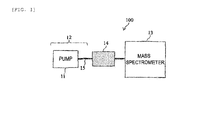
- a configuration example of a liquid chromatograph mass spectrometer according to a first embodiment will be described with reference to a schematic diagram of FIG. 1 .
- a liquid chromatograph mass spectrometer 100 is roughly formed of a liquid chromatograph 12 including a liquid feed pump 11 for feeding a mobile phase solvent 24, a mass spectrometer 13, a standard sample container 14, and a pipe 15.
- the liquid chromatograph 12 includes a column or the like in addition to the liquid feed pump 11.
- the mass spectrometer 13 performs mass spectrometry of each component according to a component separated and introduced by the column by chromatography.
- the pipe 15 allows the liquid chromatograph 12 and the mass spectrometer 13 to be connected to each other, and conveys a separated component of a measurement target sample from the liquid chromatograph 12 to the mass spectrometer 13.
- the standard sample container 14 is provided in the middle of a path of the pipe 15, and is disposed so as to be connectable in series with the liquid chromatograph 12 and the mass spectrometer 13.
- the standard sample container 14 is a container in which a standard sample solution for mass calibration is filled.
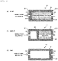
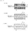
- FIG. 2(a) shows an initial state of the standard sample container 14
- FIGS. 2 (b) and 2 (c) show how a standard sample solution 23 stored inside the standard sample container 14 is pushed out.
- the standard sample container 14 is roughly formed of a case 21 and a partition plate 22.
- the case 21 has, for example, a tubular shape (for example, a cylindrical shape) in which a flow path direction is a longitudinal direction, and includes an injection hole H1 in a first wall surface 211 at one end thereof and a discharge hole H2 in a second wall surface 212 at the other end thereof.
- the partition plate 22 partitions the inside of the case 21 having the cylindrical shape in a direction intersecting a flow path, and is further disposed so as to be movable in the flow path direction (a direction connecting the injection hole H1 and the discharge hole H2).
- the standard sample solution 23 is filled between the partition plate 22 and the second wall surface 212, and the mobile phase solvent 24 is injected into a location between the first wall surface 211 and the partition plate 22.
- the mobile phase solvent 24 is introduced from the injection hole H1 and the partition plate 22 is pushed, whereby the standard sample solution 23 is discharged from the discharge hole H2.
- a shape of the injection hole H1 and the discharge hole H2 can be, for example, about 1/16 inch in diameter, and can be formed in a shape to which a pipe tube and a screw of the liquid chromatograph can be connected.
- the partition plate 22 is designed to move the inside of the case 21 in a direction from the injection hole H1 to the discharge hole H2 when a pressure of several tens of MPa is applied.
- the standard sample solution 23 is a substance obtained in a manner that a substance in which a plurality of mass numbers of ion peaks appear, such as polypropylene glycol, cesium iodide, or the like, is dissolved in water and an organic solvent such as methanol/acetonitrile or the like.
- the mobile phase solvent 24 is water or the organic solvent such as methanol/acetonitrile or the like.
- a connector 35 as shown in a cross-sectional view of FIG. 3 is attached to the injection hole H1 and the discharge hole H2 of the standard sample container 14.
- the connector 35 includes a seal plug 31, a joint 32, a screw 33, and a tube 34.
- the tube 34 is attached to the injection hole H1 or the discharge hole H2, and one end on a side of the seal plug 31 of the joint 32 is connected to the above-described pipe 15.
- the joint 32 is a cylindrical hollow member, and includes a hollow portion H3 along an axial direction of a cylinder.
- a screw hole is formed in an inner wall on one end side of the joint 32, and the seal plug 31 is screwed thereinto.
- a similar screw hole is formed in an inner wall on the other end side of the joint 32, and the screw 33 is screwed thereinto.
- the above-described pipe 15 is connected to one end of the joint 32 after the seal plug 31 is removed. Therefore, an inner diameter of one end of the joint 32 is configured to match an outer diameter of the pipe 15.
- the screw 33 includes a through hole H4 along a central axis thereof, and the tube 34 is inserted into the through hole H4.
- the connector 35 can be connected to the standard sample container 14. In this manner, the standard sample container 14 can be connected to the pipe 15 by using the screw hole of the joint 32.
- the seal plug 31 is connected to one end of the joint 32.
- the standard sample container 14 can be sealed with the seal plug 31 in a state where the inside of the standard sample container 14 is filled with the standard sample solution 23.
- the standard sample solution is left in an opened state, or it is required to repeatedly open and close a lid of a sample container after opening the lid thereof once such that the standard sample solution easily deteriorates.
- the standard sample container 14 and the connector 35 of the first embodiment are used, the standard sample solution in a single-use amount can be sealed and stored, such that the deterioration in the standard sample solution can be prevented.
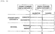
- the standard sample container 14 is connected to the pipe 15 (time t1).
- the discharge hole H2 is connected to the mass spectrometer 13 via the connector 35
- the injection hole H1 is connected to the liquid feed pump 11 via the connector 35.
- the partition plate 22 moves to a side of the injection hole H1 as shown in FIG. 2(a) , and an internal space between the partition plate 22 and the discharge hole H2 is filled with the standard sample solution 23.
- the standard sample solution 23 is pushed out of the discharge hole H2 and reaches the mass spectrometer 13 (refer to FIG. 2(b) ).
- FIG. 4 while the standard sample container 14 is connected and the standard sample solution 23 is pushed out by action of the liquid feed pump 11, an ion signal of the standard sample solution 23 is detected with a constant intensity in the mass spectrometer 13.
- the mass calibration can be performed by correcting a horizontal axis of a mass spectrum based on a peak location of the ion signal of the standard sample solution 23 in a mass spectrum measurement result.
- the standard sample container 14 is removed from the pipe 15 (time t2 in FIG. 4 ), and for example, the liquid feed pump 11 and the mass spectrometer 13 are directly connected to each other by the pipe 15.
- the mobile phase solvent 24 is fed again from the liquid feed pump 11 in this state, the standard sample solution 23 remaining in a flow path from the liquid feed pump 11 to the mass spectrometer 13 can be cleaned.
- the standard sample solution does not pass through the liquid feed pump 11 of the liquid chromatograph 12. Therefore, it is possible to prevent the liquid feed pump 11 from being contaminated by the standard sample solution.
- liquid feed pump 11 of the liquid chromatograph 12 Since the liquid feed pump 11 of the liquid chromatograph 12 is used, the number of liquid feed pumps required to be operated as the liquid chromatograph mass spectrometer can be minimized.
- FIG. 5 is a schematic diagram illustrating a configuration example of the liquid chromatograph mass spectrometer according to the second embodiment.
- the liquid chromatograph 12 includes a column mounting portion 52 for mounting a column.
- the same members as those of the first embodiment will be denoted by the same reference signs as those of FIG. 1 , and duplicated description thereof will be omitted below.
- the column mounting portion 52 is configured to be capable of selectively mounting a column 51 which is used when liquid chromatograph mass spectrometry (LC/MS) is performed, and the standard sample container 14 which is used when the mass calibration is performed.
- the column 51 and the standard sample container 14 which are mounted on the column mounting portion 52 can be connected in series between the liquid feed pump 11 and the mass spectrometer 13 via the pipe 15, when the column 51 and the standard sample container 14 are respectively used.
- a volume of the case 21 of the standard sample container 14 is the same as a volume of the column 51 or a volume that can be housed in the column mounting portion 52.
- the column mounting portion 52 is usually kept at 40 to 70°C.
- the case 21 may use a heat insulating material. By using the heat insulating material, it is possible to prevent the standard sample solution 23 in the standard sample container 14 from deteriorating by heat.
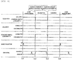
- FIG. 6 shows, as an example, a procedure in which the liquid chromatograph mass spectrometry (LC/MS), the mass calibration of the mass spectrometer 13, and the cleaning of the flow path are performed in order.
- LC/MS liquid chromatograph mass spectrometry
- the column 51 When the liquid chromatograph mass spectrometry (LC/MS) is performed, the column 51 is connected to the column mounting portion 52 (time t11 in FIG. 6 ). The column 51 is connected to the flow path from the liquid chromatograph 12 to the mass spectrometer 13 via the pipe 15. When the column 51 is connected thereto, several to several tens of ⁇ L of a sample to be analyzed is injected by a pump (not shown) and adsorbed in the column 51. Next, an appropriate mobile phase solvent is fed toward the column by the liquid feed pump 11. Accordingly, the sample to be analyzed is eluted from the column 51 and sent out to the mass spectrometer 13.
- a pump not shown
- an ion signal of a measurement substance in the sample appearing in the chromatogram appears in a peak shape having a width of several seconds at any timing between time t11 and t12.
- the mass calibration continuously starts.
- the column 51 is removed from the column mounting portion 52, and the standard sample container 14 is connected thereto instead.
- a state of the ion signal at the time of the mass calibration, a processing method, and a state of the cross-sectional view of the standard sample container 14 are the same as those of the first embodiment.
- the partition plate 22 When the partition plate 22 completely moves from the side of the injection hole H1 to the side of the discharge hole H2 inside the case 21, the ion signal does not appear in the mass spectrometer 13, such that the operation of the liquid feed pump 11 stops, and the liquid feed of the mobile phase solvent is completed. As described above, the mass calibration is completed.
- the process continuously proceeds to a flow path cleaning step.
- the standard sample container 14 connected to the column mounting portion 52 is removed, and the column 51 is connected thereto instead.
- the mobile phase solvent 24 is fed again from the liquid feed pump 11 in this state, the standard sample solution remaining in the flow path from the column mounting portion 52 to the mass spectrometer 13 can be cleaned.
- the sample is injected again and the liquid chromatograph mass spectrometry (LC/MS) is restarted in the same manner as described above.
- LC/MS liquid chromatograph mass spectrometry
- the column 51 is mounted on the column mounting portion 52 when the liquid chromatograph mass spectrometry (LC/MS) is performed, and when the mass calibration is performed, the standard sample container 14 is mounted on the column mounting portion 52 instead of the column 51. Therefore, according to the device of the second embodiment, in addition to obtaining an effect described in the first embodiment, it is possible to prevent the column 51 for the liquid chromatograph mass spectrometry from being contaminated by the standard sample solution. It is also possible to eliminate a possibility that the column 51 is clogged such that the life of the column 51 is shortened.
- LC/MS liquid chromatograph mass spectrometry
- An overall configuration of the device of the third embodiment may be the same as the overall configuration of the device of the second embodiment ( FIG. 5 ). However, in the third embodiment, a structure of the standard sample container 14 is different from that of the second embodiment.
- FIG. 7 is a schematic diagram illustrating the structure of the standard sample container 14 according to the third embodiment.
- (a) shows a state in which the standard sample container 14 does not start to be used
- (b) shows a state indicating a middle stage in which the standard sample container 14 is being used
- (c) shows a state indicating a stage in which the use of the standard sample container 14 is completed.
- this standard sample container 14 is formed of the case 21 and a tube 71 extending inside the case 21, for example, in a spiral shape.
- the standard sample solution 23 is injected into the tube 71 at a stage before the mass calibration is performed.
- a diameter (a thickness) of the tube 71 is designed so that the standard sample solution 23 is not mixed with other solutions due to diffusion.
- a material of the tube 71 is selected so as to withstand several tens of MPa of pressure generated when the liquid feed is performed by the liquid chromatograph.
- characteristics of the tube 71 are an inner diameter of 0.25 to 1.00 mm, a length of 10 to 100 cm, and a PEEK tube as a material, and the tube 71 can be selected so that an inside thereof can be filled with tens to hundreds of ⁇ L of the standard sample solution 23.
- the tube 71 is formed in the spiral shape in order to be able to store the standard sample solution 23 in the amount required for performing the mass calibration.
- a spiral is drawn so as to draw a large number of loops centered on a direction intersecting the flow path (a direction perpendicular to a paper surface), and the spiral shape is not limited to that shown in FIG. 7 .
- a direction of the loop may be centered on a direction parallel to the flow path (a direction of the paper surface).
- Disposition itself of the spiral shape of the tube 71 is also an example, and is not limited to the spiral shape.
- the tube 71 may have at least one folded portion in the case 21, such as a shape in which the tube 71 is disposed in a zigzag shape or the like.
- the tube 71 is connected between the injection hole H1 and the discharge hole H2.
- the tube 71 is pulled out from the injection hole H1 and the discharge hole H2 and connected to the pipe 15.
- the same connector 35 as that of the first embodiment may be disposed in the injection hole H1 and the discharge hole H2, and the tube 71 and the pipe 15 may be connected to each other via the connector 35.
- the connector 35 is not provided by allowing the tube 71 to have an appropriate cross-sectional diameter and to be formed in the spiral shape, leakage of the standard sample solution 23 to an outside of the tube 71 is prevented.
- the standard sample container 14 of the third embodiment is different from that of the first embodiment in that the partition plate 22 is not provided, and the standard sample solution 23 in the tube 71 receives direct pressure from the mobile phase solvent injected from one end of the tube 71 and is discharged from the other end thereof.
- the shape of the standard sample container 14 is substantially symmetrical, which is different from that of the first embodiment. Therefore, in the third embodiment, the structure of FIG. 7 may be reversed, the discharge hole H2 may be connected to a side of the liquid chromatograph 12, and the injection hole H1 may be connected to a side of the mass spectrometer 13. As will be described later, the cleaning of the flow path can also be performed while the standard sample container 14 is still connected to the flow path.
- FIG. 8 shows, as an example, a procedure in which the liquid chromatograph mass spectrometry (LC/MS), the mass calibration of the mass spectrometer 13, the cleaning of the flow path, and a Flow Injection Analysis (FIA) method are performed in order.
- LC/MS liquid chromatograph mass spectrometry
- FIA Flow Injection Analysis
- liquid chromatograph mass spectrometry LC/MS
- the mass calibration to be performed next is also performed by allowing the standard sample container 14 to be connected to the column mounting portion 52, in the same manner as that of the second embodiment.
- the connection method is also the same as that of the second embodiment.
- the standard sample container 14 is connected to the column mounting portion 52 and connected to the pipe 15, and then the mobile phase solvent 24 is fed from the liquid feed pump 11 toward the standard sample container 14.
- the mobile phase solvent 24 pushes the standard sample solution 23 in the tube 71 out toward the discharge hole H2, and the standard sample solution 23 flows toward the mass spectrometer 13.
- the mass spectrometer 13 can observe the ion signal of the standard sample solution for about 10 minutes (time t22 to t23) with a stable intensity.
- a measurement result of the standard sample solution 23 is displayed as a mass spectrum on a display device (not shown) of the mass spectrometer 13, and the mass calibration can be performed by correcting the horizontal axis of the mass spectrum based on this ion peak location.
- the process proceeds to the flow path cleaning step in the same manner as that of the second embodiment.
- the cleaning step can be performed by using the tube 71 as the flow path.
- the second embodiment is different from the third embodiment in that after the mass calibration is completed, the standard sample container 14 is replaced with the column 51 and the cleaning step is performed.
- the standard sample container 14 of the third embodiment is different from the standard sample container 14 of the first embodiment in that the partition plate 22 is not provided, and even after the standard sample solution 23 is discharged, the flow path of the tube 71 is open, and an inside of the tube 71 is filled with the mobile phase solution. Therefore, the cleaning of the flow path can be performed by continuously using the standard sample container 14 without replacing the standard sample container 14 with the column 51.
- any sample can be continuously analyzed by the Flow Injection Analysis (FIA) method using the tube 71 of the standard sample container 14.
- the FIA method is a method for performing the liquid chromatograph mass spectrometry without performing component separation by the column 51. Since the measurement can be performed quickly without using the column 51, a parameter of the measurement of the liquid chromatograph mass spectrometry can be optimized.
- the tube 71 of the standard sample container 14 can be continuously used as the flow path to be cleaned after the mass calibration is completed, a deterioration level of the column 51 can be reduced as compared with the above-described embodiment in which the cleaning is performed through the column 51.
- An overall configuration of the device of the fourth embodiment may be the same as the overall configuration of the device of the second embodiment ( FIG. 5 ). However, a structure of the standard sample container 14 of the fourth embodiment is different from that of the second embodiment.
- FIG. 9 is a schematic diagram illustrating the structure of the standard sample container 14 according to the fourth embodiment.
- the standard sample container 14 is formed of the case 21 and a filler 41 that is filled in the case 21 and can absorb the standard sample solution 23.
- the filler 41 is filled in a cavity of the case 21.
- the injection hole H1 and the discharge hole H2 provided at opposite ends of the case 21 can be configured to be connectable to the same connector ( FIG. 3 ) as that of the above-described embodiment.
- a material of the filler 41 may be the same as that of a filler to be filled in the column 51, such as silica gel or the like.
- the standard sample container 14 in the fourth embodiment is dedicated to the mass calibration, and is a container different from the column 51 to be used for the liquid chromatograph mass spectrometry.
- FIG. 10 shows, as an example, a procedure in which the liquid chromatograph mass spectrometry (LC/MS), the mass calibration of the mass spectrometer 13, and the cleaning of the flow path are performed in order.
- LC/MS liquid chromatograph mass spectrometry
- the mass calibration, and the cleaning of the flow path a connection state of the column 51 and the standard sample container 14 to the column mounting portion 52, and a sample injection operation are the same as those of the third embodiment. Therefore, duplicate description thereof will be omitted below.
- the ion signal obtained during the mass calibration is different from that of the third embodiment, and becomes a chromatogram with a peak shape such as a mountain having a wide width.
- the standard sample container 14 includes the filler 41 at the inside thereof, and the standard sample solution 23 is housed at the inside of the standard sample container 14 in a form of being absorbed by the filler 41. Since the filler 41 has high absorbency, the standard sample solution 23 of contents does not leak even in a state where the seal plug 31 of the connector 35 is loose. Therefore, the work of connecting the standard sample container 14 to the column mounting portion 52 becomes easier than that of the above-described embodiments.
- FIG. 11 is a schematic diagram illustrating a structure of the liquid chromatograph mass spectrometer according to the fifth embodiment.
- the column mounting portion 52 is configured to be capable of mounting the column 51 for the liquid chromatograph mass spectrometry and the standard sample container 14 for the mass calibration in parallel to each other at the same time.
- a valve 111a is provided between the liquid feed pump 11 and the column mounting portion 52 so that the column 51 and the standard sample container 14 can be selectively used.
- a valve 111b is provided between the column mounting portion 52 and the mass spectrometer 13. The column 51 and the standard sample container 14 are connected in parallel between the valve 111a and the valve 111b. A solution flowing through the column 51 or the standard sample container 14 is introduced into the mass spectrometer 13 via the valve 111b.
- the valves 111a and 111b are configured to selectively connect either one of the column 51 and the standard sample container 14 to the flow path.
- a plurality of columns 51 and a plurality of standard sample containers 14 may be connected to one column mounting portion 52.
- FIG. 12 shows, as an example, a procedure in which the liquid chromatograph mass spectrometry (LC/MS), the mass calibration of the mass spectrometer 13, the cleaning of the flow path, and the Flow Injection Analysis (FIA) method are performed in order.
- LC/MS liquid chromatograph mass spectrometry
- FIA Flow Injection Analysis
- the mass calibration (time t42 to t43) to be performed next is also performed by connecting the standard sample container 14 to the column mounting portion 52, in the same manner as that of the second embodiment.
- the column 51 is in a state of being always connected (mounted on) to the column mounting portion 52 even when the mass calibration is performed.
- the standard sample container 14 is also in a state of being always connected to the column mounting portion 52 when the column 51 is used.
- the new standard sample container 14 filled with the standard sample is replaced with the old standard sample container 14 that is already used.
- both the column 51 and the standard sample container 14 are always mounted on the column mounting portion 52, and only one of the column 51 and the standard sample container 14 is selectively connected to the valves 111a and 111b. Since the cleaning and the operation in the FIA are almost the same as those of the third embodiment, duplicate description thereof will be omitted.
- the column mounting portion 52 can be maintained in a state where the column 51 and the standard sample container 14 are provided in parallel to each other and are simultaneously mounted on the column mounting portion 52. Since the column 51 can be left connected to the column mounting portion 52, the column 51 can always be maintained in a warm state in the column mounting portion 52.
- FIG. 13 is a schematic diagram illustrating a structure of the liquid chromatograph mass spectrometer according to the sixth embodiment.
- the column mounting unit 52 is configured to be capable of mounting the column for the liquid chromatograph mass spectrometry and the standard sample container for the mass calibration in parallel at the same time.
- a plurality of standard sample containers 14a and 14b can be mounted on one column mounting portion 52.
- the standard sample containers 14a and 14b are containers for storing standard samples having different properties from each other.
- the standard sample container 14a can store a low molecular weight sample
- the standard sample container 14b can store a high molecular weight sample.
- the standard sample containers 14a and 14b are selected according to the properties of the samples that are routinely targets to be analyzed in the liquid chromatograph mass spectrometry. For example, when the low molecular weight sample is routinely used as a target for the liquid chromatograph mass spectrometry, basically, the mass calibration is performed by using a low molecular weight standard sample solution in the standard sample container 14a.
- the mass calibration using a high molecular weight standard sample solution in the standard sample container 14b is performed when the high molecular weight sample whose use frequency is low is used as a target for the liquid chromatograph mass spectrometry. Accordingly, in the sixth embodiment, two types of standard sample solutions stored in the standard sample containers 14a and 14b can be used appropriately according to the properties of the sample to be subjected to the liquid chromatograph mass spectrometry. Accordingly, the process of the mass calibration can be completed in a shorter time than when the mass calibration is performed in all the molecular weight regions. Cost can also be reduced as compared with the standard sample solution covering all molecular weights.
- the present invention is not limited to the above-described embodiments, and includes various modifications.
- the embodiments are described in detail in order to describe the present invention in an easy-to-understand manner, and are not necessarily limited to the one including all the configurations described above.
- a part of the configuration of one embodiment can be replaced by a configuration of another embodiment, and the configuration of another embodiment can be added to the configuration of one embodiment. It is possible to add, delete, and replace another configuration with respect to a part of the configuration of each embodiment.
Landscapes
- Physics & Mathematics (AREA)
- Health & Medical Sciences (AREA)
- Life Sciences & Earth Sciences (AREA)
- Chemical & Material Sciences (AREA)
- Analytical Chemistry (AREA)
- Biochemistry (AREA)
- General Health & Medical Sciences (AREA)
- General Physics & Mathematics (AREA)
- Immunology (AREA)
- Pathology (AREA)
- Other Investigation Or Analysis Of Materials By Electrical Means (AREA)
Abstract
Description
- The present invention relates to a liquid chromatograph mass spectrometer.
- A mass spectrometer is an analyzer that separates ions according to a mass-to-charge ratio by electrical and magnetic action and measures an abundance thereof. There are various separation methods such as a quadrupole type, a time-of-flight type, an ion trap type, or the like, and in any one of the methods, main purpose of using the analyzer is to perform qualitative analysis of a sample containing an unknown component or quantitative analysis of a sample with unknown concentration.
- When the qualitative analysis is performed, a mass spectrum is acquired, in which a horizontal axis represents a mass-to-charge ratio and a vertical axis represents an ion intensity. A mass number of an unknown sample and a structure thereof are inferred from a pattern of an ion peak in the mass spectrum. When the quantitative analysis is performed, the ion intensity at the mass-to-charge ratio specific to a substance to be quantified is measured for several minutes. By performing this measurement, a mass chromatogram in which a horizontal axis represents time and a vertical axis represents an ion intensity is acquired. Concentration of the unknown sample is calculated by obtaining a ratio of an area of a chromatogram of the unknown sample to an area of a chromatogram of a sample with known concentration.
- The mass spectrometer is often used in association with a chromatograph. The chromatograph is a device that separates a component in a mixture by using intensity of chemical or physical interaction. Examples of the chromatograph include a gas chromatograph in which a mobile phase is a gas, a liquid chromatograph in which the mobile phase is a liquid, or the like. Accuracy of the qualitative analysis and the quantitative analysis is improved by separating an impurity component from a sample with the chromatograph and then performing analysis on the sample with the mass spectrometer. When the chromatogram is used, an ion signal appears in a peak shape in the chromatogram of an analysis result of the mass spectrometer.
- Here, in any one of the qualitative analysis and quantitative analysis, an important point for maintaining the measurement accuracy is a peak location of the ion signal in a horizontal axis direction in the mass spectrum. The peak location of the ion signal is determined by values of electrical and magnetic forces applied to the mass spectrometer. The values of these forces are susceptible to an influence of a change in temperature and humidity around a device. Therefore, the peak location of the ion signal changes depending on the change in the temperature and humidity therearound, which results in a difference from a true mass-to-charge ratio. When the difference therefrom is significantly large, the qualitative analysis cannot identify what a sample to be measured is. In the quantitative analysis, there is a problem that a peak of an ion signal of a substance to be measured in the chromatogram cannot be seen.
- For the reasons described above, normally, before the mass spectrometer is used, a standard sample including the known mass number is measured to obtain the mass spectrum, and the horizontal axis of the mass spectrum is corrected based on the peak location of the ion signal. This operation is referred to as mass calibration or mass correction. In order to perform the mass calibration accurately, it is required to measure the ion signal of the standard sample for a certain period of time in a state where a sufficient amount of signals are maintained.
-
JP-A-2009-31201 -
WO 2016/103388 (PTL 2) describes that the mass calibration is performed by continuously adding a predetermined amount of a standard substance, the exact mass-to-charge ratio value of which is known and which is clearly not contained in a target sample, to eluate. - The method described in
JP-A-2009-31201 WO 2016/103388 (PTL 2) requires a unit for continuously adding the standard sample. In order to implement this unit, it is required to provide a new mechanism for controlling a continuous operation, such as a liquid feed pump which is different from the liquid feed pump of the mobile phase solvent of the liquid chromatograph. Therefore, there is a problem that introduction cost of a device is increased by an amount of a newly added unit. -
- PTL 1:
JP-A-2009-31201 - PTL 2:
WO 2016/103388 - The present invention has been made in consideration of the above-described problems, and an object thereof is to provide a liquid chromatograph mass spectrometer that prevents contamination of a pump and a column and that can perform mass calibration without adding a complicated mechanism.
- In order to solve the above-described problems, a liquid chromatograph mass spectrometer according to the present invention includes: a liquid chromatograph including a liquid feed pump configured to feed a mobile phase solvent; a mass spectrometer configured to analyze a mass of a sample; and a standard sample container configured to be connected in series with the liquid chromatograph and the mass spectrometer in a flow path that connects the liquid chromatograph and the mass spectrometer, and configured to house a standard sample for mass calibration.
- According to the present invention, it is possible to provide a liquid chromatograph mass spectrometer that prevents contamination of a pump and a column caused by a standard sample and that can perform mass calibration without adding a complicated mechanism because the mass calibration can be performed by using a pump for feeding a mobile phase solvent of a liquid chromatograph.
-
- [
FIG. 1] FIG. 1 is a schematic diagram illustrating a configuration example of a liquid chromatograph mass spectrometer according to a first embodiment. - [
FIG. 2] FIG. 2 is a cross-sectional view illustrating an example of a configuration and operation of astandard sample container 14. - [
FIG. 3] FIG. 3 is a cross-sectional view showing an example of a structure of aconnector 35 attached to an injection hole H1 and a discharge hole H2 of thestandard sample container 14. - [
FIG. 4] FIG. 4 is a timing chart illustrating an operation relating to mass calibration in the liquid chromatograph mass spectrometer ofFIG. 1 . - [
FIG. 5] FIG. 5 is a schematic diagram illustrating a configuration example of a liquid chromatograph mass spectrometer according to a second embodiment. - [
FIG. 6] FIG. 6 is a timing chart illustrating operations of liquid chromatograph mass spectrometry, mass calibration, and flow path cleaning in a liquid chromatograph mass spectrometer ofFIG. 5 . - [
FIG. 7] FIG. 7 is a schematic diagram showing a structure of astandard sample container 14 according to a third embodiment. - [
FIG. 8] FIG. 8 is a timing chart illustrating liquid chromatograph mass spectrometry, mass calibration, flow path cleaning, and FIA operations in a liquid chromatograph mass spectrometer ofFIG. 7 . - [
FIG. 9] FIG. 9 is a schematic diagram showing a structure of astandard sample container 14 according to a fourth embodiment. - [
FIG. 10] FIG. 10 is a timing chart illustrating operations of liquid chromatograph mass spectrometry, mass calibration, and flow path cleaning in a liquid chromatograph mass spectrometer ofFIG. 9 . - [
FIG. 11] FIG. 11 is a schematic diagram illustrating a configuration example of a liquid chromatograph mass spectrometer according to a fifth embodiment. - [
FIG. 12] FIG. 12 is a timing chart illustrating an operation of a liquid chromatograph mass spectrometer ofFIG. 11 . - [
FIG. 13] FIG. 13 is a schematic diagram illustrating a configuration example of a liquid chromatograph mass spectrometer according to a sixth embodiment. - Hereinafter, embodiments will be described with reference to the accompanying drawings. In the accompanying drawings, a functionally identical element may be represented by the same number or a corresponding number. While the accompanying drawings show embodiments and implementation examples based on a principle of the present disclosure, the drawings are provided for understanding of the present disclosure and are by no means used for limited interpretation of the present disclosure. Description of this specification is only a typical example, and does not limit the scope of the claims of the present disclosure or an application example thereof in any sense.
- The embodiment is sufficiently described in detail for those skilled in the art to implement the present disclosure, and it is required to understand that other implementations and forms are can be performed, and that it is possible to change a configuration and structure and to replace various elements without departing from the scope and spirit of a technical idea of the present disclosure. Therefore, the following description should not be construed as being limited thereto.
- A configuration example of a liquid chromatograph mass spectrometer according to a first embodiment will be described with reference to a schematic diagram of
FIG. 1 . A liquidchromatograph mass spectrometer 100 is roughly formed of aliquid chromatograph 12 including aliquid feed pump 11 for feeding a mobile phase solvent 24, amass spectrometer 13, astandard sample container 14, and apipe 15. - Although not shown in
FIG. 1 , theliquid chromatograph 12 includes a column or the like in addition to theliquid feed pump 11. Themass spectrometer 13 performs mass spectrometry of each component according to a component separated and introduced by the column by chromatography. - The
pipe 15 allows theliquid chromatograph 12 and themass spectrometer 13 to be connected to each other, and conveys a separated component of a measurement target sample from theliquid chromatograph 12 to themass spectrometer 13. Thestandard sample container 14 is provided in the middle of a path of thepipe 15, and is disposed so as to be connectable in series with theliquid chromatograph 12 and themass spectrometer 13. Thestandard sample container 14 is a container in which a standard sample solution for mass calibration is filled. - An example of a configuration of the
standard sample container 14 will be described together with an operation thereof with reference to a cross-sectional view ofFIG. 2. FIG. 2(a) shows an initial state of thestandard sample container 14, andFIGS. 2 (b) and 2 (c) show how astandard sample solution 23 stored inside thestandard sample container 14 is pushed out. - As an example, the
standard sample container 14 is roughly formed of acase 21 and apartition plate 22. Thecase 21 has, for example, a tubular shape (for example, a cylindrical shape) in which a flow path direction is a longitudinal direction, and includes an injection hole H1 in afirst wall surface 211 at one end thereof and a discharge hole H2 in asecond wall surface 212 at the other end thereof. Thepartition plate 22 partitions the inside of thecase 21 having the cylindrical shape in a direction intersecting a flow path, and is further disposed so as to be movable in the flow path direction (a direction connecting the injection hole H1 and the discharge hole H2). That is, in thestandard sample container 14, thestandard sample solution 23 is filled between thepartition plate 22 and thesecond wall surface 212, and the mobile phase solvent 24 is injected into a location between thefirst wall surface 211 and thepartition plate 22. As shown inFIGS. 2(b) and 2(c) , the mobile phase solvent 24 is introduced from the injection hole H1 and thepartition plate 22 is pushed, whereby thestandard sample solution 23 is discharged from the discharge hole H2. A shape of the injection hole H1 and the discharge hole H2 can be, for example, about 1/16 inch in diameter, and can be formed in a shape to which a pipe tube and a screw of the liquid chromatograph can be connected. - The
partition plate 22 is designed to move the inside of thecase 21 in a direction from the injection hole H1 to the discharge hole H2 when a pressure of several tens of MPa is applied. For example, it is desirable that thestandard sample solution 23 is a substance obtained in a manner that a substance in which a plurality of mass numbers of ion peaks appear, such as polypropylene glycol, cesium iodide, or the like, is dissolved in water and an organic solvent such as methanol/acetonitrile or the like. On the other hand, it is desirable that the mobile phase solvent 24 is water or the organic solvent such as methanol/acetonitrile or the like. - For example, a
connector 35 as shown in a cross-sectional view ofFIG. 3 is attached to the injection hole H1 and the discharge hole H2 of thestandard sample container 14. Theconnector 35 includes aseal plug 31, a joint 32, ascrew 33, and atube 34. Thetube 34 is attached to the injection hole H1 or the discharge hole H2, and one end on a side of theseal plug 31 of the joint 32 is connected to the above-describedpipe 15. - The joint 32 is a cylindrical hollow member, and includes a hollow portion H3 along an axial direction of a cylinder. A screw hole is formed in an inner wall on one end side of the joint 32, and the
seal plug 31 is screwed thereinto. A similar screw hole is formed in an inner wall on the other end side of the joint 32, and thescrew 33 is screwed thereinto. The above-describedpipe 15 is connected to one end of the joint 32 after theseal plug 31 is removed. Therefore, an inner diameter of one end of the joint 32 is configured to match an outer diameter of thepipe 15. - The
screw 33 includes a through hole H4 along a central axis thereof, and thetube 34 is inserted into the through hole H4. When thescrew 33 into which thetube 34 is inserted is connected to the joint 32 and thetube 34 is further fixed to the injection hole H1, theconnector 35 can be connected to thestandard sample container 14. In this manner, thestandard sample container 14 can be connected to thepipe 15 by using the screw hole of the joint 32. - When the
standard sample container 14 is carried, theseal plug 31 is connected to one end of the joint 32. Thestandard sample container 14 can be sealed with theseal plug 31 in a state where the inside of thestandard sample container 14 is filled with thestandard sample solution 23. In related art, the standard sample solution is left in an opened state, or it is required to repeatedly open and close a lid of a sample container after opening the lid thereof once such that the standard sample solution easily deteriorates. On the other hand, when thestandard sample container 14 and theconnector 35 of the first embodiment are used, the standard sample solution in a single-use amount can be sealed and stored, such that the deterioration in the standard sample solution can be prevented. - Next, with reference to a timing chart of
FIG. 4 , an operation related to the mass calibration in the liquid chromatograph mass spectrometer ofFIG. 1 will be described. In the device ofFIG. 1 , when the mass calibration is started, thestandard sample container 14 is connected to the pipe 15 (time t1). When thestandard sample container 14 is connected thereto, the discharge hole H2 is connected to themass spectrometer 13 via theconnector 35, and the injection hole H1 is connected to theliquid feed pump 11 via theconnector 35. In thestandard sample container 14 at the start of the mass calibration, thepartition plate 22 moves to a side of the injection hole H1 as shown inFIG. 2(a) , and an internal space between thepartition plate 22 and the discharge hole H2 is filled with thestandard sample solution 23. - After the
standard sample container 14 is connected to theliquid feed pump 11 and themass spectrometer 13 via thepipe 15, liquid feed of the mobile phase solvent 24 from the liquid feed pump 11 starts. Since a pressure at the time of the liquid feed of the mobile phase solvent 24 is several tens of MPa, thepartition plate 22 of thestandard sample container 14 moves in thecase 21 with the liquid feed thereof. - As the
partition plate 22 moves, thestandard sample solution 23 is pushed out of the discharge hole H2 and reaches the mass spectrometer 13 (refer toFIG. 2(b) ). As shown inFIG. 4 , while thestandard sample container 14 is connected and thestandard sample solution 23 is pushed out by action of theliquid feed pump 11, an ion signal of thestandard sample solution 23 is detected with a constant intensity in themass spectrometer 13. The mass calibration can be performed by correcting a horizontal axis of a mass spectrum based on a peak location of the ion signal of thestandard sample solution 23 in a mass spectrum measurement result. - As shown in
FIG. 2(c) , when thepartition plate 22 reaches the other end of thecase 21, the ion signal of thestandard sample solution 23 is not observed in themass spectrometer 13. At this time, thecase 21 is in a state of being filled with themobile phase solvent 24. When the ion signal of thestandard sample solution 23 is not observed in themass spectrometer 13, theliquid feed pump 11 is stopped and the liquid feed of the mobile phase solvent 24 is stopped. - After that, the
standard sample container 14 is removed from the pipe 15 (time t2 inFIG. 4 ), and for example, theliquid feed pump 11 and themass spectrometer 13 are directly connected to each other by thepipe 15. When the mobile phase solvent 24 is fed again from theliquid feed pump 11 in this state, thestandard sample solution 23 remaining in a flow path from theliquid feed pump 11 to themass spectrometer 13 can be cleaned. - As described above, according to the configuration of the liquid chromatograph mass spectrometer of the first embodiment, as described in
JP-A-2009-31201 liquid feed pump 11 of theliquid chromatograph 12. Therefore, it is possible to prevent the liquid feed pump 11 from being contaminated by the standard sample solution. - Since the
liquid feed pump 11 of theliquid chromatograph 12 is used, the number of liquid feed pumps required to be operated as the liquid chromatograph mass spectrometer can be minimized. - Next, a liquid chromatograph mass spectrometer according to a second embodiment will be described with reference to
FIGS. 5 and6 .FIG. 5 is a schematic diagram illustrating a configuration example of the liquid chromatograph mass spectrometer according to the second embodiment. In the liquid chromatograph mass spectrometer of the second embodiment, theliquid chromatograph 12 includes acolumn mounting portion 52 for mounting a column. InFIG. 5 , the same members as those of the first embodiment will be denoted by the same reference signs as those ofFIG. 1 , and duplicated description thereof will be omitted below. - The
column mounting portion 52 is configured to be capable of selectively mounting acolumn 51 which is used when liquid chromatograph mass spectrometry (LC/MS) is performed, and thestandard sample container 14 which is used when the mass calibration is performed. Thecolumn 51 and thestandard sample container 14 which are mounted on thecolumn mounting portion 52 can be connected in series between theliquid feed pump 11 and themass spectrometer 13 via thepipe 15, when thecolumn 51 and thestandard sample container 14 are respectively used. - As the
standard sample container 14, the one shown inFIG. 2 can be adopted as an example. However, a volume of thecase 21 of thestandard sample container 14 is the same as a volume of thecolumn 51 or a volume that can be housed in thecolumn mounting portion 52. Thecolumn mounting portion 52 is usually kept at 40 to 70°C. In order to cope with such an environment, thecase 21 may use a heat insulating material. By using the heat insulating material, it is possible to prevent thestandard sample solution 23 in thestandard sample container 14 from deteriorating by heat. - Next, an operation of the liquid chromatograph mass spectrometer of
FIG. 5 will be described with reference to a timing chart ofFIG. 6. FIG. 6 shows, as an example, a procedure in which the liquid chromatograph mass spectrometry (LC/MS), the mass calibration of themass spectrometer 13, and the cleaning of the flow path are performed in order. - When the liquid chromatograph mass spectrometry (LC/MS) is performed, the
column 51 is connected to the column mounting portion 52 (time t11 inFIG. 6 ). Thecolumn 51 is connected to the flow path from theliquid chromatograph 12 to themass spectrometer 13 via thepipe 15. When thecolumn 51 is connected thereto, several to several tens of µL of a sample to be analyzed is injected by a pump (not shown) and adsorbed in thecolumn 51. Next, an appropriate mobile phase solvent is fed toward the column by theliquid feed pump 11. Accordingly, the sample to be analyzed is eluted from thecolumn 51 and sent out to themass spectrometer 13. - When the mass spectrometry is performed on the sample to be analyzed sent out therefrom with the
mass spectrometer 13, for example, an ion signal of a measurement substance in the sample appearing in the chromatogram appears in a peak shape having a width of several seconds at any timing between time t11 and t12. - When the liquid chromatograph mass spectrometry is completed, the mass calibration continuously starts. In this case, the
column 51 is removed from thecolumn mounting portion 52, and thestandard sample container 14 is connected thereto instead. A state of the ion signal at the time of the mass calibration, a processing method, and a state of the cross-sectional view of thestandard sample container 14 are the same as those of the first embodiment. - When the
partition plate 22 completely moves from the side of the injection hole H1 to the side of the discharge hole H2 inside thecase 21, the ion signal does not appear in themass spectrometer 13, such that the operation of theliquid feed pump 11 stops, and the liquid feed of the mobile phase solvent is completed. As described above, the mass calibration is completed. - When the mass calibration is completed, the process continuously proceeds to a flow path cleaning step. When the ion signal is not observed and the operation of the
liquid feed pump 11 is stopped, continuously, thestandard sample container 14 connected to thecolumn mounting portion 52 is removed, and thecolumn 51 is connected thereto instead. When the mobile phase solvent 24 is fed again from theliquid feed pump 11 in this state, the standard sample solution remaining in the flow path from thecolumn mounting portion 52 to themass spectrometer 13 can be cleaned. After cleaning the flow path, the sample is injected again and the liquid chromatograph mass spectrometry (LC/MS) is restarted in the same manner as described above. - As described above, in the device of the second embodiment, the
column 51 is mounted on thecolumn mounting portion 52 when the liquid chromatograph mass spectrometry (LC/MS) is performed, and when the mass calibration is performed, thestandard sample container 14 is mounted on thecolumn mounting portion 52 instead of thecolumn 51. Therefore, according to the device of the second embodiment, in addition to obtaining an effect described in the first embodiment, it is possible to prevent thecolumn 51 for the liquid chromatograph mass spectrometry from being contaminated by the standard sample solution. It is also possible to eliminate a possibility that thecolumn 51 is clogged such that the life of thecolumn 51 is shortened. - Next, a liquid chromatograph mass spectrometer according to a third embodiment will be described with reference to
FIGS. 7 and8 . An overall configuration of the device of the third embodiment may be the same as the overall configuration of the device of the second embodiment (FIG. 5 ). However, in the third embodiment, a structure of thestandard sample container 14 is different from that of the second embodiment. -
FIG. 7 is a schematic diagram illustrating the structure of thestandard sample container 14 according to the third embodiment. InFIG. 7, (a) shows a state in which thestandard sample container 14 does not start to be used, (b) shows a state indicating a middle stage in which thestandard sample container 14 is being used, and (c) shows a state indicating a stage in which the use of thestandard sample container 14 is completed. - As an example, this
standard sample container 14 is formed of thecase 21 and atube 71 extending inside thecase 21, for example, in a spiral shape. Thestandard sample solution 23 is injected into thetube 71 at a stage before the mass calibration is performed. A diameter (a thickness) of thetube 71 is designed so that thestandard sample solution 23 is not mixed with other solutions due to diffusion. A material of thetube 71 is selected so as to withstand several tens of MPa of pressure generated when the liquid feed is performed by the liquid chromatograph. As an example, characteristics of thetube 71 are an inner diameter of 0.25 to 1.00 mm, a length of 10 to 100 cm, and a PEEK tube as a material, and thetube 71 can be selected so that an inside thereof can be filled with tens to hundreds of µL of thestandard sample solution 23. - The
tube 71 is formed in the spiral shape in order to be able to store thestandard sample solution 23 in the amount required for performing the mass calibration. InFIG. 7 , a spiral is drawn so as to draw a large number of loops centered on a direction intersecting the flow path (a direction perpendicular to a paper surface), and the spiral shape is not limited to that shown inFIG. 7 . For example, a direction of the loop may be centered on a direction parallel to the flow path (a direction of the paper surface). Disposition itself of the spiral shape of thetube 71 is also an example, and is not limited to the spiral shape. For example, instead of having the spiral shape, thetube 71 may have at least one folded portion in thecase 21, such as a shape in which thetube 71 is disposed in a zigzag shape or the like. - The
tube 71 is connected between the injection hole H1 and the discharge hole H2. Thetube 71 is pulled out from the injection hole H1 and the discharge hole H2 and connected to thepipe 15. Thesame connector 35 as that of the first embodiment may be disposed in the injection hole H1 and the discharge hole H2, and thetube 71 and thepipe 15 may be connected to each other via theconnector 35. However, even though theconnector 35 is not provided by allowing thetube 71 to have an appropriate cross-sectional diameter and to be formed in the spiral shape, leakage of thestandard sample solution 23 to an outside of thetube 71 is prevented. - The
standard sample container 14 of the third embodiment is different from that of the first embodiment in that thepartition plate 22 is not provided, and thestandard sample solution 23 in thetube 71 receives direct pressure from the mobile phase solvent injected from one end of thetube 71 and is discharged from the other end thereof. The shape of thestandard sample container 14 is substantially symmetrical, which is different from that of the first embodiment. Therefore, in the third embodiment, the structure ofFIG. 7 may be reversed, the discharge hole H2 may be connected to a side of theliquid chromatograph 12, and the injection hole H1 may be connected to a side of themass spectrometer 13. As will be described later, the cleaning of the flow path can also be performed while thestandard sample container 14 is still connected to the flow path. - Next, an operation of the liquid chromatograph mass spectrometer of
FIG. 7 will be described with reference to a timing chart ofFIG. 8. FIG. 8 shows, as an example, a procedure in which the liquid chromatograph mass spectrometry (LC/MS), the mass calibration of themass spectrometer 13, the cleaning of the flow path, and a Flow Injection Analysis (FIA) method are performed in order. - Since the liquid chromatograph mass spectrometry (LC/MS) can be performed in almost the same manner as that of the second embodiment (
FIG. 6 ), duplicate description thereof will be omitted. The mass calibration to be performed next is also performed by allowing thestandard sample container 14 to be connected to thecolumn mounting portion 52, in the same manner as that of the second embodiment. The connection method is also the same as that of the second embodiment. - When the mass calibration is performed, the
standard sample container 14 is connected to thecolumn mounting portion 52 and connected to thepipe 15, and then the mobile phase solvent 24 is fed from theliquid feed pump 11 toward thestandard sample container 14. Next, as shown inFIG. 7(b) , the mobile phase solvent 24 pushes thestandard sample solution 23 in thetube 71 out toward the discharge hole H2, and thestandard sample solution 23 flows toward themass spectrometer 13. - On the assumption that a flow rate is several to several tens of µL / min, the
mass spectrometer 13 can observe the ion signal of the standard sample solution for about 10 minutes (time t22 to t23) with a stable intensity. A measurement result of thestandard sample solution 23 is displayed as a mass spectrum on a display device (not shown) of themass spectrometer 13, and the mass calibration can be performed by correcting the horizontal axis of the mass spectrum based on this ion peak location. - When the mass calibration is completed, the process proceeds to the flow path cleaning step in the same manner as that of the second embodiment. However, in the third embodiment, after the mass calibration is completed, in a state where the
standard sample container 14 is still mounted on thecolumn mounting portion 52, the cleaning step can be performed by using thetube 71 as the flow path. In this point, the second embodiment is different from the third embodiment in that after the mass calibration is completed, thestandard sample container 14 is replaced with thecolumn 51 and the cleaning step is performed. Thestandard sample container 14 of the third embodiment is different from thestandard sample container 14 of the first embodiment in that thepartition plate 22 is not provided, and even after thestandard sample solution 23 is discharged, the flow path of thetube 71 is open, and an inside of thetube 71 is filled with the mobile phase solution. Therefore, the cleaning of the flow path can be performed by continuously using thestandard sample container 14 without replacing thestandard sample container 14 with thecolumn 51. - When the cleaning step is completed, any sample can be continuously analyzed by the Flow Injection Analysis (FIA) method using the
tube 71 of thestandard sample container 14. The FIA method is a method for performing the liquid chromatograph mass spectrometry without performing component separation by thecolumn 51. Since the measurement can be performed quickly without using thecolumn 51, a parameter of the measurement of the liquid chromatograph mass spectrometry can be optimized. - In the analysis by the FIA method, in a state where the
standard sample container 14 is connected to thecolumn mounting portion 52, several to several tens of µL of any sample is injected while the appropriate mobile phase solvent is fed from theliquid feed pump 11. Since the sample to be analyzed is slightly diffused until the sample to be analyzed reaches themass spectrometer 13, a peak width of the ion signal in the chromatogram is slightly wider than that of a case where the sample to be analyzed passes through thecolumn 51. After the analysis by the FIA method is completed, thestandard sample container 14 is removed from thecolumn mounting portion 52, thecolumn 51 is connected thereto instead, and the liquid chromatograph mass spectrometry is performed again. - As described above, according to the
standard sample container 14 of the third embodiment, since thetube 71 of thestandard sample container 14 can be continuously used as the flow path to be cleaned after the mass calibration is completed, a deterioration level of thecolumn 51 can be reduced as compared with the above-described embodiment in which the cleaning is performed through thecolumn 51. - Next, a liquid chromatograph mass spectrometer according to a fourth embodiment will be described with reference to
FIGS. 9 and10 . An overall configuration of the device of the fourth embodiment may be the same as the overall configuration of the device of the second embodiment (FIG. 5 ). However, a structure of thestandard sample container 14 of the fourth embodiment is different from that of the second embodiment. -
FIG. 9 is a schematic diagram illustrating the structure of thestandard sample container 14 according to the fourth embodiment. Thestandard sample container 14 is formed of thecase 21 and afiller 41 that is filled in thecase 21 and can absorb thestandard sample solution 23. Thefiller 41 is filled in a cavity of thecase 21. The injection hole H1 and the discharge hole H2 provided at opposite ends of thecase 21 can be configured to be connectable to the same connector (FIG. 3 ) as that of the above-described embodiment. - A material of the
filler 41 may be the same as that of a filler to be filled in thecolumn 51, such as silica gel or the like. However, thestandard sample container 14 in the fourth embodiment is dedicated to the mass calibration, and is a container different from thecolumn 51 to be used for the liquid chromatograph mass spectrometry. - Next, an operation of the liquid chromatograph mass spectrometer of
FIG. 9 will be described with reference to a timing chart ofFIG. 10. FIG. 10 shows, as an example, a procedure in which the liquid chromatograph mass spectrometry (LC/MS), the mass calibration of themass spectrometer 13, and the cleaning of the flow path are performed in order. During the liquid chromatograph mass spectrometry (LC/MS), the mass calibration, and the cleaning of the flow path, a connection state of thecolumn 51 and thestandard sample container 14 to thecolumn mounting portion 52, and a sample injection operation are the same as those of the third embodiment. Therefore, duplicate description thereof will be omitted below. However, the ion signal obtained during the mass calibration is different from that of the third embodiment, and becomes a chromatogram with a peak shape such as a mountain having a wide width. - In the fourth embodiment, the
standard sample container 14 includes thefiller 41 at the inside thereof, and thestandard sample solution 23 is housed at the inside of thestandard sample container 14 in a form of being absorbed by thefiller 41. Since thefiller 41 has high absorbency, thestandard sample solution 23 of contents does not leak even in a state where theseal plug 31 of theconnector 35 is loose. Therefore, the work of connecting thestandard sample container 14 to thecolumn mounting portion 52 becomes easier than that of the above-described embodiments. - Continuously, a liquid chromatograph mass spectrometer according to a fifth embodiment will be described with reference to
FIGS. 11 and12 .FIG. 11 is a schematic diagram illustrating a structure of the liquid chromatograph mass spectrometer according to the fifth embodiment. In the device of the fifth embodiment, thecolumn mounting portion 52 is configured to be capable of mounting thecolumn 51 for the liquid chromatograph mass spectrometry and thestandard sample container 14 for the mass calibration in parallel to each other at the same time. - A
valve 111a is provided between theliquid feed pump 11 and thecolumn mounting portion 52 so that thecolumn 51 and thestandard sample container 14 can be selectively used. Avalve 111b is provided between thecolumn mounting portion 52 and themass spectrometer 13. Thecolumn 51 and thestandard sample container 14 are connected in parallel between thevalve 111a and thevalve 111b. A solution flowing through thecolumn 51 or thestandard sample container 14 is introduced into themass spectrometer 13 via thevalve 111b. Thevalves column 51 and thestandard sample container 14 to the flow path. A plurality ofcolumns 51 and a plurality ofstandard sample containers 14 may be connected to onecolumn mounting portion 52. - Next, an operation of the liquid chromatograph mass spectrometer of
FIG. 11 will be described with reference to a timing chart ofFIG. 12. FIG. 12 shows, as an example, a procedure in which the liquid chromatograph mass spectrometry (LC/MS), the mass calibration of themass spectrometer 13, the cleaning of the flow path, and the Flow Injection Analysis (FIA) method are performed in order. - Since the liquid chromatograph mass spectrometry (time t41 to t42 in
FIG. 12 ) can be performed in almost the same manner as that of the second embodiment (FIG. 6 ), duplicate description thereof will be omitted. The mass calibration (time t42 to t43) to be performed next is also performed by connecting thestandard sample container 14 to thecolumn mounting portion 52, in the same manner as that of the second embodiment. However, in an operation example ofFIG. 12 , thecolumn 51 is in a state of being always connected (mounted on) to thecolumn mounting portion 52 even when the mass calibration is performed. Thestandard sample container 14 is also in a state of being always connected to thecolumn mounting portion 52 when thecolumn 51 is used. However, when the mass calibration starts (for example, time t42), the newstandard sample container 14 filled with the standard sample is replaced with the oldstandard sample container 14 that is already used. As described above, both thecolumn 51 and thestandard sample container 14 are always mounted on thecolumn mounting portion 52, and only one of thecolumn 51 and thestandard sample container 14 is selectively connected to thevalves - As described above, in the fifth embodiment, the
column mounting portion 52 can be maintained in a state where thecolumn 51 and thestandard sample container 14 are provided in parallel to each other and are simultaneously mounted on thecolumn mounting portion 52. Since thecolumn 51 can be left connected to thecolumn mounting portion 52, thecolumn 51 can always be maintained in a warm state in thecolumn mounting portion 52. - Continuously, a liquid chromatograph mass spectrometer according to a sixth embodiment will be described with reference to
FIG. 13. FIG. 13 is a schematic diagram illustrating a structure of the liquid chromatograph mass spectrometer according to the sixth embodiment. In the device of the sixth embodiment, in the same manner as that of the fifth embodiment, thecolumn mounting unit 52 is configured to be capable of mounting the column for the liquid chromatograph mass spectrometry and the standard sample container for the mass calibration in parallel at the same time. In the sixth embodiment, a plurality ofstandard sample containers column mounting portion 52. - The
standard sample containers standard sample container 14a can store a low molecular weight sample, and thestandard sample container 14b can store a high molecular weight sample. Thestandard sample containers standard sample container 14a. The mass calibration using a high molecular weight standard sample solution in thestandard sample container 14b is performed when the high molecular weight sample whose use frequency is low is used as a target for the liquid chromatograph mass spectrometry. Accordingly, in the sixth embodiment, two types of standard sample solutions stored in thestandard sample containers - The present invention is not limited to the above-described embodiments, and includes various modifications. For example, the embodiments are described in detail in order to describe the present invention in an easy-to-understand manner, and are not necessarily limited to the one including all the configurations described above. A part of the configuration of one embodiment can be replaced by a configuration of another embodiment, and the configuration of another embodiment can be added to the configuration of one embodiment. It is possible to add, delete, and replace another configuration with respect to a part of the configuration of each embodiment.
-
- 11
- liquid feed pump
- 12
- liquid chromatograph
- 13
- mass spectrometer
- 14
- standard sample container
- 15
- pipe
- 21
- case
- 22
- partition plate
- 23
- standard sample solution
- 24
- mobile phase solvent
- 31
- seal plug
- 32
- joint
- 33
- screw
- 34
- tube
- 35
- connector
- 41
- filler
- 51
- column
- 52
- column mounting portion
- 71
- tube
- 111
- valve
Claims (8)
- A liquid chromatograph mass spectrometer, comprising:a liquid chromatograph including a liquid feed pump configured to feed a mobile phase solvent;a mass spectrometer configured to analyze a mass of a sample; anda standard sample container configured to be connected in series with the liquid chromatograph and the mass spectrometer in a flow path that connects the liquid chromatograph and the mass spectrometer, and configured to house a standard sample for mass calibration.
- The liquid chromatograph mass spectrometer according to claim 1, wherein
the standard sample container includes:a cylindrical case that includes an injection hole at a first end and a discharge hole at a second end and that has a flow path direction as a longitudinal direction, anda partition plate configured to be movable along an inner wall of the case and partitioning an inside of the case, and wherein
the partition plate is configured to be movable in a direction of the discharge hole due to movement of a mobile phase solution from the injection hole. - The liquid chromatograph mass spectrometer according to claim 1, wherein
the standard sample container includes:a case that includes an injection hole at a first end and a discharge hole at a second end, anda tube connected between the injection hole and the discharge hole in the case and including at least one folded portion in the case. - The liquid chromatograph mass spectrometer according to claim 3, wherein
the tube is arranged in a spiral shape in the case. - The liquid chromatograph mass spectrometer according to claim 1, wherein
the standard sample container includes:a case that includes an injection hole at a first end and a discharge hole at a second end, anda filler filled in the case and capable of absorbing standard sample solution. - The liquid chromatograph mass spectrometer according to claim 1, further comprising:
a column mounting portion configured to be capable of mounting the standard sample container. - The liquid chromatograph mass spectrometer according to claim 6, whereinthe column mounting portion is configured to be capable of mounting the standard sample container and a column used for liquid chromatograph mass spectrometry in parallel, and whereinthe liquid chromatograph mass spectrometer further includes a valve configured to selectively connect the standard sample container or the column to a flow path.
- The liquid chromatograph mass spectrometer according to claim 6 or 7, wherein
the column mounting portion is configured to be capable of mounting a plurality of standard sample containers that respectively house standard sample solutions having different properties.
Applications Claiming Priority (2)
| Application Number | Priority Date | Filing Date | Title |
|---|---|---|---|
| JP2019018250 | 2019-02-04 | ||
| PCT/JP2020/004067 WO2020162438A1 (en) | 2019-02-04 | 2020-02-04 | Liquid chromatograph mass spectrometer |
Publications (3)
| Publication Number | Publication Date |
|---|---|
| EP3922989A1 true EP3922989A1 (en) | 2021-12-15 |
| EP3922989A4 EP3922989A4 (en) | 2022-10-26 |
| EP3922989B1 EP3922989B1 (en) | 2024-11-20 |
Family
ID=71947766
Family Applications (1)
| Application Number | Title | Priority Date | Filing Date |
|---|---|---|---|
| EP20752632.8A Active EP3922989B1 (en) | 2019-02-04 | 2020-02-04 | Liquid chromatograph mass spectrometer |
Country Status (5)
| Country | Link |
|---|---|
| US (1) | US11635413B2 (en) |
| EP (1) | EP3922989B1 (en) |
| JP (1) | JP7297799B2 (en) |
| CN (1) | CN113383232B (en) |
| WO (1) | WO2020162438A1 (en) |
Families Citing this family (2)
| Publication number | Priority date | Publication date | Assignee | Title |
|---|---|---|---|---|
| US12669484B2 (en) * | 2022-12-12 | 2026-06-30 | Thermo Finnigan Llc | Lock mass correction during chromatography void time |
| CN116672916B (en) * | 2023-07-28 | 2023-11-17 | 北京凯莱谱生物科技有限公司 | Chromatograph with mixed wave reduction device and detection method thereof |
Family Cites Families (28)
| Publication number | Priority date | Publication date | Assignee | Title |
|---|---|---|---|---|
| JP3203054B2 (en) * | 1992-07-30 | 2001-08-27 | 株式会社日立製作所 | Liquid chromatograph mass spectrometer |
| JP3087548B2 (en) * | 1993-12-09 | 2000-09-11 | 株式会社日立製作所 | Liquid chromatograph coupled mass spectrometer |
| US5585070A (en) * | 1994-04-29 | 1996-12-17 | Phoenix International Life Sciences Inc. | Method for extraction, extraction cartridge and automated extraction processing system |
| JP3235775B2 (en) * | 1996-07-09 | 2001-12-04 | 株式会社日立製作所 | Liquid chromatograph direct mass spectrometry method and apparatus |
| US5703360A (en) | 1996-08-30 | 1997-12-30 | Hewlett-Packard Company | Automated calibrant system for use in a liquid separation/mass spectrometry apparatus |
| US6502448B1 (en) * | 1999-09-07 | 2003-01-07 | Edward Rapkin | Chromatography detection system and method |
| US6526811B2 (en) * | 2000-02-23 | 2003-03-04 | Jmic, Inc. | Analytical apparatus for measurement of low concentration constituent, method of measurement and calibration using the same |
| JP3725826B2 (en) * | 2002-01-21 | 2005-12-14 | 株式会社日立ハイテクノロジーズ | Exhaust gas measuring device and its standard sample generator |
| JP4306491B2 (en) * | 2004-02-27 | 2009-08-05 | 株式会社島津製作所 | Liquid chromatograph |
| JP4577280B2 (en) | 2006-07-05 | 2010-11-10 | 株式会社島津製作所 | Liquid chromatograph mass spectrometer |
| JP4966780B2 (en) | 2007-07-30 | 2012-07-04 | 株式会社日立ハイテクノロジーズ | Analysis method using liquid chromatograph / mass spectrometer |
| ES2436744T3 (en) * | 2007-08-24 | 2014-01-07 | Emd Millipore Corporation | System to derive a liquid chromatography eluent |
| KR101018789B1 (en) * | 2009-02-25 | 2011-03-03 | 한국원자력연구원 | Batch Gas Chromatography Measurement Device by Quantitative Injection of Negative Pressure Gas Sample with High Vacuum Multiple Gas Sample Introduction |
| WO2012058515A2 (en) * | 2010-10-29 | 2012-05-03 | Thermo Finnigan Llc | Modular multiple-column chromatography cartridge |
| US20150072360A1 (en) * | 2011-12-14 | 2015-03-12 | The Johns Hopkins University | Biomarkers of pulmonary hypertension |
| WO2014068786A1 (en) | 2012-11-05 | 2014-05-08 | 株式会社島津製作所 | Chromatographic analyzing device |
| JP2015075355A (en) * | 2013-10-07 | 2015-04-20 | 株式会社島津製作所 | Chromatograph mass analyzer |
| JP6156662B2 (en) * | 2013-10-28 | 2017-07-05 | 株式会社島津製作所 | Multi-quantitative analysis method using chromatograph |
| EP3092483B1 (en) * | 2014-01-10 | 2019-07-31 | Purehoney Technologies, Inc. | Mass-spectrometer systems and methods |
| EP3160609B1 (en) * | 2014-06-25 | 2019-08-14 | Purehoney Technologies, Inc. | Automated sample fractionation prior to mass spectrometric analysis |
| WO2016002045A1 (en) * | 2014-07-03 | 2016-01-07 | 株式会社島津製作所 | Mass spectrometer |
| JP6380555B2 (en) | 2014-12-25 | 2018-08-29 | 株式会社島津製作所 | Analysis equipment |
| CN104931609B (en) * | 2015-05-28 | 2017-03-01 | 浙江省中医药研究院 | Device associated with a kind of hollow fiber membrane liquid-phase micro extraction liquid chromatograph and its polysaccharide component on-line quantitative analysis method |
| WO2017094178A1 (en) * | 2015-12-04 | 2017-06-08 | 株式会社島津製作所 | Liquid sample analysis system |
| KR101795885B1 (en) * | 2015-12-22 | 2017-11-10 | 연세대학교 산학협력단 | High speed on-line lipid extraction device, system and method for extracting and analyzing lipid from biological sample using the device |
| JP6533749B2 (en) * | 2016-01-20 | 2019-06-19 | 日本電子株式会社 | Mass spectrometer and mass spectrometry method |
| WO2018003011A1 (en) * | 2016-06-28 | 2018-01-04 | 株式会社島津製作所 | Analysis device |
| JP7156154B2 (en) * | 2019-04-18 | 2022-10-19 | 株式会社島津製作所 | Medium processing system and medium processing method |
-
2020
- 2020-02-04 WO PCT/JP2020/004067 patent/WO2020162438A1/en not_active Ceased
- 2020-02-04 US US17/424,526 patent/US11635413B2/en active Active
- 2020-02-04 JP JP2020571207A patent/JP7297799B2/en active Active
- 2020-02-04 EP EP20752632.8A patent/EP3922989B1/en active Active
- 2020-02-04 CN CN202080012274.6A patent/CN113383232B/en active Active
Also Published As
| Publication number | Publication date |
|---|---|
| WO2020162438A1 (en) | 2020-08-13 |
| JPWO2020162438A1 (en) | 2020-08-13 |
| JP7297799B2 (en) | 2023-06-26 |
| EP3922989A4 (en) | 2022-10-26 |
| US20220074901A1 (en) | 2022-03-10 |
| CN113383232B (en) | 2023-09-19 |
| EP3922989B1 (en) | 2024-11-20 |
| US11635413B2 (en) | 2023-04-25 |
| CN113383232A (en) | 2021-09-10 |
Similar Documents
| Publication | Publication Date | Title |
|---|---|---|
| Beccaria et al. | Current developments in LC-MS for pharmaceutical analysis | |
| US10309928B2 (en) | Apparatus and method for ion mobility spectrometry and sample introduction | |
| US10317362B2 (en) | Analysis of isomers in TIMS-Q-q-tof mass spectrometers | |
| US8829430B2 (en) | Pulsed mass calibration in time-of-flight mass spectrometry | |
| US11635413B2 (en) | Liquid chromatograph mass spectrometer | |
| Noga et al. | A practical guide to nano‐LC troubleshooting | |
| US20080237458A1 (en) | Automated mass spectral identification | |
| US7260978B2 (en) | Gas chromatography/mass spectrometry system | |
| EP3370062B1 (en) | Gas chromatograph and sample injection method | |
| GB2575726A (en) | Bench-top time of flight mass spectrometer | |
| US20200340957A1 (en) | Analysis Device | |
| CN112601958B (en) | quality correction | |
| US9299545B2 (en) | Systems and methods for calibrating mass spectrometers | |
| US7189965B2 (en) | Storage device for molecular detector | |
| Ramsey et al. | Direct aqueous supercritical fluid extraction coupled on-line with liquid chromatography–tandem mass spectrometry for the analysis of polyether ionophore antibiotics in water | |
| US11047828B2 (en) | Method for controlling the mass filter in a hybrid IMS/MS system | |
| Han et al. | Integration of a liquid-phase ion trap with a miniature mass spectrometer | |
| WO2017149794A1 (en) | Chromatograph device | |
| CN110243958A (en) | A method for analyzing components of complex geological samples | |
| MacAskill et al. | Recent Advances in Water Analysis with Gas Chromatograph Mass Spectrometers | |
| US20190333750A1 (en) | Mass spectrometer and program for mass spectrometer | |
| Stokes et al. | Modification of a gas chromatography/atmospheric pressure chemical ionisation time‐of‐flight mass spectrometer as an alternative to automated atmospheric pressure solids analysis probe | |
| Prajapat et al. | BIOANALYTICAL METHOD DEVELOPMENT AND VALIDATION FOR ESTIMATION OF PRIMIDONE IN K3EDTA HUMAN PLASMA BY USING LC-MS/MS | |
| MacAskill et al. | 44th International Conference on Environmental Systems ICES-2014-316 13-17 July 2014, Tucson, Arizona Recent Advances in Water Analysis with Gas Chromatograph Mass Spectrometers | |
| Huang et al. | Determination of polar pesticides in grapes using a compact ion chromatography system coupled with tandem mass spectrometry |
Legal Events
| Date | Code | Title | Description |
|---|---|---|---|
| STAA | Information on the status of an ep patent application or granted ep patent |
Free format text: STATUS: THE INTERNATIONAL PUBLICATION HAS BEEN MADE |
|
| PUAI | Public reference made under article 153(3) epc to a published international application that has entered the european phase |
Free format text: ORIGINAL CODE: 0009012 |
|
| STAA | Information on the status of an ep patent application or granted ep patent |
Free format text: STATUS: REQUEST FOR EXAMINATION WAS MADE |
|
| 17P | Request for examination filed |
Effective date: 20210906 |
|
| AK | Designated contracting states |
Kind code of ref document: A1 Designated state(s): AL AT BE BG CH CY CZ DE DK EE ES FI FR GB GR HR HU IE IS IT LI LT LU LV MC MK MT NL NO PL PT RO RS SE SI SK SM TR |
|
| DAV | Request for validation of the european patent (deleted) | ||
| DAX | Request for extension of the european patent (deleted) | ||
| A4 | Supplementary search report drawn up and despatched |
Effective date: 20220928 |
|
| RIC1 | Information provided on ipc code assigned before grant |
Ipc: G01N 30/46 20060101ALN20220922BHEP Ipc: G01N 30/72 20060101ALI20220922BHEP Ipc: G01N 30/62 20060101AFI20220922BHEP |
|
| REG | Reference to a national code |
Ref country code: DE Ref legal event code: R079 Ref document number: 602020041690 Country of ref document: DE Free format text: PREVIOUS MAIN CLASS: G01N0030020000 Ipc: G01N0030620000 |
|
| GRAP | Despatch of communication of intention to grant a patent |
Free format text: ORIGINAL CODE: EPIDOSNIGR1 |
|
| STAA | Information on the status of an ep patent application or granted ep patent |
Free format text: STATUS: GRANT OF PATENT IS INTENDED |
|
| RIC1 | Information provided on ipc code assigned before grant |
Ipc: G01N 30/46 20060101ALN20240701BHEP Ipc: G01N 30/72 20060101ALI20240701BHEP Ipc: G01N 30/62 20060101AFI20240701BHEP |
|
| RIC1 | Information provided on ipc code assigned before grant |
Ipc: G01N 30/46 20060101ALN20240712BHEP Ipc: G01N 30/72 20060101ALI20240712BHEP Ipc: G01N 30/62 20060101AFI20240712BHEP |
|
| INTG | Intention to grant announced |
Effective date: 20240724 |
|
| GRAS | Grant fee paid |
Free format text: ORIGINAL CODE: EPIDOSNIGR3 |
|
| GRAA | (expected) grant |
Free format text: ORIGINAL CODE: 0009210 |
|
| STAA | Information on the status of an ep patent application or granted ep patent |
Free format text: STATUS: THE PATENT HAS BEEN GRANTED |
|
| AK | Designated contracting states |
Kind code of ref document: B1 Designated state(s): AL AT BE BG CH CY CZ DE DK EE ES FI FR GB GR HR HU IE IS IT LI LT LU LV MC MK MT NL NO PL PT RO RS SE SI SK SM TR |
|
| REG | Reference to a national code |
Ref country code: GB Ref legal event code: FG4D |
|
| REG | Reference to a national code |
Ref country code: CH Ref legal event code: EP |
|
| REG | Reference to a national code |
Ref country code: DE Ref legal event code: R096 Ref document number: 602020041690 Country of ref document: DE |
|
| REG | Reference to a national code |
Ref country code: IE Ref legal event code: FG4D |
|
| REG | Reference to a national code |
Ref country code: LT Ref legal event code: MG9D |
|
| REG | Reference to a national code |
Ref country code: NL Ref legal event code: MP Effective date: 20241120 |
|
| PG25 | Lapsed in a contracting state [announced via postgrant information from national office to epo] |
Ref country code: HR Free format text: LAPSE BECAUSE OF FAILURE TO SUBMIT A TRANSLATION OF THE DESCRIPTION OR TO PAY THE FEE WITHIN THE PRESCRIBED TIME-LIMIT Effective date: 20241120 Ref country code: IS Free format text: LAPSE BECAUSE OF FAILURE TO SUBMIT A TRANSLATION OF THE DESCRIPTION OR TO PAY THE FEE WITHIN THE PRESCRIBED TIME-LIMIT Effective date: 20250320 Ref country code: PT Free format text: LAPSE BECAUSE OF FAILURE TO SUBMIT A TRANSLATION OF THE DESCRIPTION OR TO PAY THE FEE WITHIN THE PRESCRIBED TIME-LIMIT Effective date: 20250320 |
|
| PG25 | Lapsed in a contracting state [announced via postgrant information from national office to epo] |
Ref country code: FI Free format text: LAPSE BECAUSE OF FAILURE TO SUBMIT A TRANSLATION OF THE DESCRIPTION OR TO PAY THE FEE WITHIN THE PRESCRIBED TIME-LIMIT Effective date: 20241120 Ref country code: NL Free format text: LAPSE BECAUSE OF FAILURE TO SUBMIT A TRANSLATION OF THE DESCRIPTION OR TO PAY THE FEE WITHIN THE PRESCRIBED TIME-LIMIT Effective date: 20241120 |
|
| REG | Reference to a national code |
Ref country code: AT Ref legal event code: MK05 Ref document number: 1744002 Country of ref document: AT Kind code of ref document: T Effective date: 20241120 |
|
| PG25 | Lapsed in a contracting state [announced via postgrant information from national office to epo] |
Ref country code: BG Free format text: LAPSE BECAUSE OF FAILURE TO SUBMIT A TRANSLATION OF THE DESCRIPTION OR TO PAY THE FEE WITHIN THE PRESCRIBED TIME-LIMIT Effective date: 20241120 |
|
| PG25 | Lapsed in a contracting state [announced via postgrant information from national office to epo] |
Ref country code: ES Free format text: LAPSE BECAUSE OF FAILURE TO SUBMIT A TRANSLATION OF THE DESCRIPTION OR TO PAY THE FEE WITHIN THE PRESCRIBED TIME-LIMIT Effective date: 20241120 |
|
| PG25 | Lapsed in a contracting state [announced via postgrant information from national office to epo] |
Ref country code: NO Free format text: LAPSE BECAUSE OF FAILURE TO SUBMIT A TRANSLATION OF THE DESCRIPTION OR TO PAY THE FEE WITHIN THE PRESCRIBED TIME-LIMIT Effective date: 20250220 |
|
| PG25 | Lapsed in a contracting state [announced via postgrant information from national office to epo] |
Ref country code: LV Free format text: LAPSE BECAUSE OF FAILURE TO SUBMIT A TRANSLATION OF THE DESCRIPTION OR TO PAY THE FEE WITHIN THE PRESCRIBED TIME-LIMIT Effective date: 20241120 Ref country code: GR Free format text: LAPSE BECAUSE OF FAILURE TO SUBMIT A TRANSLATION OF THE DESCRIPTION OR TO PAY THE FEE WITHIN THE PRESCRIBED TIME-LIMIT Effective date: 20250221 Ref country code: AT Free format text: LAPSE BECAUSE OF FAILURE TO SUBMIT A TRANSLATION OF THE DESCRIPTION OR TO PAY THE FEE WITHIN THE PRESCRIBED TIME-LIMIT Effective date: 20241120 |
|
| PG25 | Lapsed in a contracting state [announced via postgrant information from national office to epo] |
Ref country code: PL Free format text: LAPSE BECAUSE OF FAILURE TO SUBMIT A TRANSLATION OF THE DESCRIPTION OR TO PAY THE FEE WITHIN THE PRESCRIBED TIME-LIMIT Effective date: 20241120 |
|
| PG25 | Lapsed in a contracting state [announced via postgrant information from national office to epo] |
Ref country code: RS Free format text: LAPSE BECAUSE OF FAILURE TO SUBMIT A TRANSLATION OF THE DESCRIPTION OR TO PAY THE FEE WITHIN THE PRESCRIBED TIME-LIMIT Effective date: 20250220 |
|
| PG25 | Lapsed in a contracting state [announced via postgrant information from national office to epo] |
Ref country code: SM Free format text: LAPSE BECAUSE OF FAILURE TO SUBMIT A TRANSLATION OF THE DESCRIPTION OR TO PAY THE FEE WITHIN THE PRESCRIBED TIME-LIMIT Effective date: 20241120 |
|
| PG25 | Lapsed in a contracting state [announced via postgrant information from national office to epo] |
Ref country code: DK Free format text: LAPSE BECAUSE OF FAILURE TO SUBMIT A TRANSLATION OF THE DESCRIPTION OR TO PAY THE FEE WITHIN THE PRESCRIBED TIME-LIMIT Effective date: 20241120 |
|
| PG25 | Lapsed in a contracting state [announced via postgrant information from national office to epo] |
Ref country code: EE Free format text: LAPSE BECAUSE OF FAILURE TO SUBMIT A TRANSLATION OF THE DESCRIPTION OR TO PAY THE FEE WITHIN THE PRESCRIBED TIME-LIMIT Effective date: 20241120 |
|
| PG25 | Lapsed in a contracting state [announced via postgrant information from national office to epo] |
Ref country code: RO Free format text: LAPSE BECAUSE OF FAILURE TO SUBMIT A TRANSLATION OF THE DESCRIPTION OR TO PAY THE FEE WITHIN THE PRESCRIBED TIME-LIMIT Effective date: 20241120 |
|
| PG25 | Lapsed in a contracting state [announced via postgrant information from national office to epo] |
Ref country code: SK Free format text: LAPSE BECAUSE OF FAILURE TO SUBMIT A TRANSLATION OF THE DESCRIPTION OR TO PAY THE FEE WITHIN THE PRESCRIBED TIME-LIMIT Effective date: 20241120 |
|
| PG25 | Lapsed in a contracting state [announced via postgrant information from national office to epo] |
Ref country code: CZ Free format text: LAPSE BECAUSE OF FAILURE TO SUBMIT A TRANSLATION OF THE DESCRIPTION OR TO PAY THE FEE WITHIN THE PRESCRIBED TIME-LIMIT Effective date: 20241120 |
|
| PG25 | Lapsed in a contracting state [announced via postgrant information from national office to epo] |
Ref country code: IT Free format text: LAPSE BECAUSE OF FAILURE TO SUBMIT A TRANSLATION OF THE DESCRIPTION OR TO PAY THE FEE WITHIN THE PRESCRIBED TIME-LIMIT Effective date: 20241120 |
|
| REG | Reference to a national code |
Ref country code: DE Ref legal event code: R097 Ref document number: 602020041690 Country of ref document: DE |
|
| PG25 | Lapsed in a contracting state [announced via postgrant information from national office to epo] |
Ref country code: SE Free format text: LAPSE BECAUSE OF FAILURE TO SUBMIT A TRANSLATION OF THE DESCRIPTION OR TO PAY THE FEE WITHIN THE PRESCRIBED TIME-LIMIT Effective date: 20241120 |
|
| PG25 | Lapsed in a contracting state [announced via postgrant information from national office to epo] |
Ref country code: MC Free format text: LAPSE BECAUSE OF FAILURE TO SUBMIT A TRANSLATION OF THE DESCRIPTION OR TO PAY THE FEE WITHIN THE PRESCRIBED TIME-LIMIT Effective date: 20241120 |
|
| PLBE | No opposition filed within time limit |
Free format text: ORIGINAL CODE: 0009261 |
|
| STAA | Information on the status of an ep patent application or granted ep patent |
Free format text: STATUS: NO OPPOSITION FILED WITHIN TIME LIMIT |
|
| REG | Reference to a national code |
Ref country code: CH Ref legal event code: PL |
|
| PG25 | Lapsed in a contracting state [announced via postgrant information from national office to epo] |
Ref country code: LU Free format text: LAPSE BECAUSE OF NON-PAYMENT OF DUE FEES Effective date: 20250204 |
|
| PG25 | Lapsed in a contracting state [announced via postgrant information from national office to epo] |
Ref country code: CH Free format text: LAPSE BECAUSE OF NON-PAYMENT OF DUE FEES Effective date: 20250228 |
|
| 26N | No opposition filed |
Effective date: 20250821 |
|
| REG | Reference to a national code |
Ref country code: BE Ref legal event code: MM Effective date: 20250228 |
|
| PG25 | Lapsed in a contracting state [announced via postgrant information from national office to epo] |
Ref country code: FR Free format text: LAPSE BECAUSE OF NON-PAYMENT OF DUE FEES Effective date: 20250228 |
|
| PG25 | Lapsed in a contracting state [announced via postgrant information from national office to epo] |
Ref country code: BE Free format text: LAPSE BECAUSE OF NON-PAYMENT OF DUE FEES Effective date: 20250228 |
|
| PG25 | Lapsed in a contracting state [announced via postgrant information from national office to epo] |
Ref country code: IE Free format text: LAPSE BECAUSE OF NON-PAYMENT OF DUE FEES Effective date: 20250204 |
|
| PGFP | Annual fee paid to national office [announced via postgrant information from national office to epo] |
Ref country code: GB Payment date: 20260219 Year of fee payment: 7 |
|
| PGFP | Annual fee paid to national office [announced via postgrant information from national office to epo] |
Ref country code: DE Payment date: 20260228 Year of fee payment: 7 |
|
| PG25 | Lapsed in a contracting state [announced via postgrant information from national office to epo] |
Ref country code: CY Free format text: LAPSE BECAUSE OF FAILURE TO SUBMIT A TRANSLATION OF THE DESCRIPTION OR TO PAY THE FEE WITHIN THE PRESCRIBED TIME-LIMIT Effective date: 20241120 |
|
| PG25 | Lapsed in a contracting state [announced via postgrant information from national office to epo] |
Ref country code: TR Free format text: LAPSE BECAUSE OF FAILURE TO SUBMIT A TRANSLATION OF THE DESCRIPTION OR TO PAY THE FEE WITHIN THE PRESCRIBED TIME-LIMIT Effective date: 20241120 |
|
| PG25 | Lapsed in a contracting state [announced via postgrant information from national office to epo] |
Ref country code: LT Free format text: LAPSE BECAUSE OF FAILURE TO SUBMIT A TRANSLATION OF THE DESCRIPTION OR TO PAY THE FEE WITHIN THE PRESCRIBED TIME-LIMIT Effective date: 20241120 |