EP3922970B1 - Temperature detector for induction heating system - Google Patents
Temperature detector for induction heating system Download PDFInfo
- Publication number
- EP3922970B1 EP3922970B1 EP21178646.2A EP21178646A EP3922970B1 EP 3922970 B1 EP3922970 B1 EP 3922970B1 EP 21178646 A EP21178646 A EP 21178646A EP 3922970 B1 EP3922970 B1 EP 3922970B1
- Authority
- EP
- European Patent Office
- Prior art keywords
- housing
- grommet
- extends
- temperature detector
- resting surface
- Prior art date
- Legal status (The legal status is an assumption and is not a legal conclusion. Google has not performed a legal analysis and makes no representation as to the accuracy of the status listed.)
- Active
Links
Images




Classifications
-
- G—PHYSICS
- G01—MEASURING; TESTING
- G01K—MEASURING TEMPERATURE; MEASURING QUANTITY OF HEAT; THERMALLY-SENSITIVE ELEMENTS NOT OTHERWISE PROVIDED FOR
- G01K13/00—Thermometers specially adapted for specific purposes
-
- H—ELECTRICITY
- H05—ELECTRIC TECHNIQUES NOT OTHERWISE PROVIDED FOR
- H05B—ELECTRIC HEATING; ELECTRIC LIGHT SOURCES NOT OTHERWISE PROVIDED FOR; CIRCUIT ARRANGEMENTS FOR ELECTRIC LIGHT SOURCES, IN GENERAL
- H05B6/00—Heating by electric, magnetic or electromagnetic fields
- H05B6/02—Induction heating
- H05B6/10—Induction heating apparatus, other than furnaces, for specific applications
- H05B6/12—Cooking devices
- H05B6/1209—Cooking devices induction cooking plates or the like and devices to be used in combination with them
-
- G—PHYSICS
- G01—MEASURING; TESTING
- G01K—MEASURING TEMPERATURE; MEASURING QUANTITY OF HEAT; THERMALLY-SENSITIVE ELEMENTS NOT OTHERWISE PROVIDED FOR
- G01K1/00—Details of thermometers not specially adapted for particular types of thermometer
- G01K1/08—Protective devices, e.g. casings
-
- G—PHYSICS
- G01—MEASURING; TESTING
- G01K—MEASURING TEMPERATURE; MEASURING QUANTITY OF HEAT; THERMALLY-SENSITIVE ELEMENTS NOT OTHERWISE PROVIDED FOR
- G01K1/00—Details of thermometers not specially adapted for particular types of thermometer
- G01K1/14—Supports; Fastening devices; Arrangements for mounting thermometers in particular locations
- G01K1/143—Supports; Fastening devices; Arrangements for mounting thermometers in particular locations for measuring surface temperatures
-
- G—PHYSICS
- G01—MEASURING; TESTING
- G01K—MEASURING TEMPERATURE; MEASURING QUANTITY OF HEAT; THERMALLY-SENSITIVE ELEMENTS NOT OTHERWISE PROVIDED FOR
- G01K2207/00—Application of thermometers in household appliances
- G01K2207/02—Application of thermometers in household appliances for measuring food temperature
- G01K2207/06—Application of thermometers in household appliances for measuring food temperature for preparation purposes
-
- H—ELECTRICITY
- H05—ELECTRIC TECHNIQUES NOT OTHERWISE PROVIDED FOR
- H05B—ELECTRIC HEATING; ELECTRIC LIGHT SOURCES NOT OTHERWISE PROVIDED FOR; CIRCUIT ARRANGEMENTS FOR ELECTRIC LIGHT SOURCES, IN GENERAL
- H05B2213/00—Aspects relating both to resistive heating and to induction heating, covered by H05B3/00 and H05B6/00
- H05B2213/07—Heating plates with temperature control means
Definitions
- the subject disclosure relates to induction heaters that are configured to receive pans of food products or liquids to be heated within the pan.
- Induction heaters often include temperature detectors that measure the temperature of a pan that is disposed within the induction heater with the measured temperature used to control the operation of the induction coil via feedback control. Often the temperature detectors deform permanently or elastically with use which decreases the life of the temperature detector. Temperature detectors also frequently receive spillage from the contents that are disposed within the pan (liquid or solids) that degrade the surfaces of the temperature detector, which often requires replacement or maintenance or recalibration of the temperature detector.
- the subject disclosure is directed to a temperature detector that is configured to maintain good contact with a pan disposed thereon for accurate temperature detection and therefore efficient operation. The disclosed temperature detector is also designed to withstand spillage for long operation between required maintenance or replacement.
- US2017/142780 describes an induction cooker which has a temperature sensor mount that includes a reciprocity sensor holder and a flexible diaphragm.
- An aspect of the invention provides a system as set out in claim 1.
- the embodiment includes a temperature detector.
- the temperature detector includes an RTD and associated wiring, a first housing that receives the RTD, and a grommet disposed around the first housing.
- the temperature detector further comprises a cylindrical second housing that supports and receives a portion of the first housing therewith and through a first end of the second housing.
- the grommet includes an arcuate portion that is biased in a direction upwardly from the resting surface, the arcuate portion comprises a central opening through which the first housing extends, wherein the central opening defines a inner circular surface that is disposed between the first and second housings.
- an induction heating system comprises an induction coil, a resting surface, and a temperature detector disposed upon the resting surface such that a pan that is disposed upon the resting surface contacts the temperature detector;
- the temperature detector comprises an RTD and associated wiring, a first housing that receives the RTD, and a grommet disposed around the first housing, the temperature detector further comprises a cylindrical second housing that supports and receives a portion of the first housing therewith and through a first end of the second housing, wherein the grommet includes an arcuate portion that is biased in a direction upwardly from the resting surface, the arcuate portion comprises a central opening through which the first housing extends, wherein the central opening defines an inner circular surface that is disposed between the first and second housings.
- the system may further comprise an end cap that extends into the second housing through a second end of the second housing, wherein the end cap contacts the inner surface of the second housing.
- the inner surface of the second housing may be threaded along at least a portion of its length, and wherein the first housing and the second make a threaded connection, and wherein the end cap makes a threaded connection with the second housing.
- the associated wiring of the RTD may extend through the first housing, the central opening in the grommet, and the second housing.
- the grommet may further comprise a ledge and a cantilevered portion, wherein the arcuate portion extends from the cantilevered portion, the arcuate portion defines the central opening.
- the portion of the resting surface may be disposed between the cantilevered portion and the ledge.
- the grommet may be circular and the ledge, cantilevered portion, and the arcuate portion may each extend around the circumference of the grommet.
- the system may further comprise a support disk that is disposed below the ledge, the support disk includes a center portion with an aperture though which the second housing extends, the center portion an inverse conical portion with a side wall that extends downwardly toward the aperture, wherein the inverse conical portion is disposed below the arcuate portion of the grommet.
- the arcuate portion of the grommet may be urged downwardly when a pan is positioned upon the first housing, and wherein the first housing and the second housing are also urged downwardly.
- the arcuate portion of the grommet may contact the center portion of the support disk when urged downwardly when the pan is positioned upon the first housing.
- the second housing and first housing may be urged upwardly by a spring disposed below the second housing and wherein the first and second housings are urged downwardly against the upward urging force of the spring when a pan is disposed upon the first housing.
- the first housing may be aluminum.
- the grommet may be an elastomeric material.
- the resting surface may be circular and may include a center aperture through which the temperature detector extends, further comprising a side wall that contacts an outer circumferential sidewall of the resting surface and extends above a top surface of the resting surface.
- the temperature detector may comprise a plurality of temperature detectors, wherein the resting surface is rectangular and includes a plurality of spaced apertures through each of the plurality of temperature detectors extend, further comprising a side wall that contacts and outer surface of the resting surface and extends above a top surface of the resting surface.
- An aspect provides a temperature detector, comprising: an RTD and associated wiring, a first housing that receives the RTD, and a grommet disposed around the first housing, the temperature detector further comprises a cylindrical second housing that supports and receives a portion of the first housing therewith and through a first end of the second housing, wherein the grommet includes an arcuate portion that is biased in a direction upwardly from the resting surface, the arcuate portion comprises a central opening through which the first housing extends, wherein the central opening defines a inner circular surface that is disposed between the first and second housings.
- the system may further comprise an end cap that extends into the second housing through a second end of the second housing, wherein the end cap contacts the inner surface of the second housing.
- the inner surface of the second housing may be threaded along at least a portion of its length, and wherein the first housing and the second make a threaded connection, and wherein the end cap makes a threaded connection with the second housing.
- the associated wiring from the RTD may extend through the first housing, the central opening in the grommet, and the second housing.
- the grommet may comprise a ledge, a cantilevered portion, and an arcuate portion, wherein the arcuate portion extends from the cantilevered portion, the arcuate portion defines the central opening.
- the grommet may be circular and the ledge, cantilevered portion, and the arcuate portion each extend around the circumference of the circular grommet.
- the system may further comprise a support disk, that is disposed below the ledge, the support disk includes a center portion with an aperture though which the second housing extends, the center portion an inverse conical portion with a side wall that extends downwardly toward the aperture, wherein the inverse conical portion is disposed below the arcuate portion of the grommet.
- the first housing may be aluminum.
- the grommet may be an elastomeric material. The arcuate portion of the grommet may be urged downwardly when a pan is positioned upon the first housing, and wherein the first housing and the second housing are also urged downwardly.
- the induction heating device includes a housing 24, a side wall 30, a resting surface 20, an induction coil 3000, and a temperature detector 100 that is disposed upon the resting surface 20 and positioned such that the temperature detector 100 is contacted by a bottom surface 1020 of a pan 1010 when the pan is positioned within the heating device.
- This specification depicts two different shaped heating devices, a circular device ( FIG. 1 ) that includes a single temperature detector 100 disposed at the center of the resting surface 20, and a rectangular device 2010 ( FIG. 1a ) that includes three temperature detectors 100 that are disposed at different positions upon the resting surface 2020, such as along a center line and consistently spaced from each other.
- induction heating devices with different shapes, sizes, and number of temperature detectors 100 can be provided.
- the induction heating device 10 may be disposed within an aperture in a counter 1000 ( FIG. 6 ) in a restaurant, banquet facility, or kitchen, other location where food is to be maintained heated for serving or cooking. In other embodiments, the induction heating device 10 may be disposed within in a housing.
- the induction coil 3000 may be disposed below the resting surface 20 and in some embodiments the induction coil 3000 may also be disposed within the side wall 30 of the device 10 so that the magnetic fields generated by the induction coils 3000 are directed simultaneously to different portions of the pan 1010 for faster heating of the pan 1010 (and therefore the contents of the pan) and also for more uniform heating of the contents of the pan.
- the induction coil 3000 is operated to create a magnetic field that induces an eddy current in the pan 1010 when disposed thereon, as is known in the art.
- the temperature detector 100 may include a RTD 129 (resistance temperature detector) or it may be another form of temperature detector known in the art, which is configured to measure temperature and provide a signal to a controller 4000 for feedback control purposes regarding operation of the induction coil 3000. While RTDs are specifically discussed herein for the sake of brevity, the use of the term "RTD" when describing its use within the temperature detector applies to other temperature detection devices that are known in the art.
- the induction heating device 10 may include an input and display where the user can monitor the temperature of the device as well as input a desired temperature for the device. The input and display may communicate with the controller 400 and also include timers, information regarding the contents of the pan within the device.
- the input and display may be provided with the device, and also may communicate with a remote input display upon an app on a phone or tablet, a computer, and the like via a cellular signal, Wi-Fi, Bluetooth or via other known communication manners, which may operate via conventional or proprietary internet of things protocols.
- the controller 4000 may additionally or alternatively communicate with a POS system and/or a restaurant network, automated recipe system, inventory system, or other databases or systems found within restaurant or other facility.
- the temperature detector 100 may include a support 180 that supports a plurality of components thereon.
- the support 180 may be fixed to the resting surface 20, such as with a plurality of fasteners.
- the support 180 may be disposed below the resting surface 20, i.e. below the bottom surface 20b of the resting surface, which is opposite from the upper surface 20a that the pan rests upon.
- the support 180 includes a central pocket 182 and an outer resting surface 188.
- the central pocket 182 receives the second housing 150 and a portion of the central portion 162 of the support disk 150 ( FIG. 5 ).
- the central pocket 182 includes a cylindrical portion 183 and a bottom wall 184.
- the bottom wall 184 has an aperture through which the wire 109 of the RTD (discussed below) extends.
- the bottom wall 184 may also receive a spring 190 thereupon that extends between the end cap 170 (when provided, otherwise the second housing 150) and applies an upward biasing force upon the second housing 150 (when provided through the end cap 170) that is transferred to the first housing 120 and the grommet 140 to urge the first housing 120 and grommet 140 upwardly with respect to the resting surface 20 and the support disk 160, so that the temperature detector normally extends above the support disk 160 as depicted in FIGs. 6 and 6a .
- the outer resting surface 188 of the support 180 is a flat surface that extends outwardly from the central pocket 182.
- the outer resting surface extends parallel and below the resting surface 20 and may be fixed to the resting surface 20 with a plurality of fasteners that extend through a one or preferably multiple apertures in the outer resting surface 188 (and also extend through aligned holes in the outer support portion 168 of the support disk 160 and the ledge 148 of the grommet 140 (each discussed below)).
- the temperature detector 100 further includes a first housing 120, a grommet 140 and a second housing 150. In some embodiments, the temperature detector 100 further includes an end cap 170 that is connectable to the second housing 160, as discussed below.
- the temperature detector may further include a support disk 160.
- the first housing 120 is best understood with reference to FIGs. 5 , 6a , 7a , and 8 .
- the first housing 120 receives and supports the RTD 129.
- the first housing 120 includes a top surface 122 that with a central portion 127 that faces upward and includes a ledge portion 126 that extends outwardly from a body portion 124.
- the ledge portion 126 may be curved downwardly from the central portion and may have an outer circumferential portion 126b that extends in a downward direction.
- the first housing 120 may be established wherein the top to bottom cross-section of the first housing (i.e. a cross-section that extends through the longitudinal axis 2 of the first housing 120 ( FIG. 8 )) is the same around the entire circumference of the first housing, other than the threads 124a that extend along the body portion 124 and from the outer surface of the body portion 124 in embodiments that include threads 124a.
- the RTD 129 may be disposed within a cavity 125 formed within the body portion and below the top surface and fixed in contact with an inner surface of the top surface 122, such that the RTD 129 receives conduction heat transfer that extends through the top surface 122.
- the cavity 125 may be filled with a material, such as an epoxy or other material to prevent foreign material from entering the cavity 125 and interfering with the operation of the RTD.
- the material that fills the cavity 125 may have a relatively low thermal conductivity (such as a thermal conductivity that is much lower than the thermal conductivity of the material, such as aluminum, that forms the top surface 122 of the first housing 120) such that environmental heat, such as heat from the induction coils does not substantially communicate with the RTD during operation such that the output of the RTD is closely related to the heat flowing through the top surface 122 to the RTD 129 from the pan and not from other heat sources.
- the first housing 120 is connected and extends within the second housing 150.
- the second housing 150 may include a ledge 153 at a top end thereof that has a diameter greater than an outer diameter of the body 152. Similar to the first housing, the second housing 150 may be established such that a top to bottom cross-section of the second housing 150 (that extends through the longitudinal axis 2 of the second housing) is the same around the entire circumference of the second housing 150, other than the inner threads within the 155 through the second housing.
- the second housing 150 includes top and bottom holes and an inner cavity/lumen that extends therethrough, which may be threaded. The body 124 of the first housing 120 through the top hole and threadably engages the second housing to fix the two components to each other.
- the ledge 153 of the second housing includes a horizontal surface 153a and an upstanding surface 153b that is disposed at the edge portion of the ledge 153.
- the upstanding surface 153b of the second housing is aligned with the downwardly extending circumferential portion 126b, which receives a portion of the grommet 140 therebetween. As shown in FIG.
- a void is formed inboard of the alignment between the upstanding surface 153b and the downwardly extending circumferential portion 126b that receives an inner circular surface of the grommet 140 therein, which has a height that is greater than a space between the upstanding surface 153b and the downwardly extending circumferential portion 126b to securely retain the grommet 140 with respect to the first and second housings 120, 150.
- An end cap 170 may be provided, which has a ledge portion 172 and a body portion 174, with the ledge portion 172 having a larger outer diameter than the body portion 174.
- the end cap may have a cavity that extends through the end cap, through which the wire 109 (when provided) extends (which also extends through the cavity in the second housing 150.
- the body portion 174 may be threaded and the body portion may extend within a hole at the bottom of the second housing and threadably connect with the second housing 150 such that the ledge portion 172 contacts the bottom end of the second housing 150 when assembled.
- the outer diameter of the ledge portion 172 of the end cap 170 may be larger than the outer diameter of the body 154 of the second housing, such that an inner flange of the support disk 160 rests upon the ledge portion 172 when the temperature detector is assembled as shown in FIG. 5 .
- the first housing 120, the grommet 140, the second housing 150, and the end cap 170 may be aligned along the same longitudinal axis 2 and may be connectable to each other via the threaded connections discussed above, with the grommet 140 disposed between the ledges of the first and second housing, and in some embodiments with the portion of the grommet 140 extending between the ledges being locally compressed by the first and second housings 120, 140.
- the support disk 160 is best shown in FIGs. 5 , 6a , 7a , 9 , and 9a.
- the support disk 160 includes a center portion 162 with an aperture therethrough (through which the second housing 150 extends), and an outer support portion 168.
- the outer support portion 168 defines the outer portion of the support disk and is flat and when assembled rests upon the outer resting surface 188 of the support 180.
- the center portion 162 includes an outer cylindrical portion 163 that extends upwardly from the outer resting portion 168 and an inverse conical portion 164 that extends downwardly toward a central aperture.
- the inverse conical portion includes an upper facing surface that has a straight cross-section ( FIG. 5 ), and is projected about its central longitudinal axis (2) a full 360 degrees, to establish the inverse of a cone around center portion 162.
- the center portion 162 may define a curved surface (along the entire surface or a portion of the surface) that extends downwardly toward the central aperture which may also extend a full 360 degrees around the central longitudinal axis (2).
- the top surface 165 of the center portion is disposed at a similar (or the same) height as the top surface 20a of the resting surface 20, which allows the arcuate portion 142 of the grommet 140 to be compressed such the grommet does not extend above the ledge 147 of the grommet when the grommet 140 and first housing 120 are urged downwardly by a pan resting thereon ( FIG. 7a ).
- the center portion 162 forms a central aperture, that is defined by an inner flange 166 that extends within the pocket 182 of the support 180 and in some embodiments contacts the end cap 170.
- the second housing extends within the inner flange 166 of the center portion, which supports the second housing 150.
- the grommet 140 is best shown in FIGs. 5 , 6a , 7a , and 8 .
- the grommet may be made from an elastomeric material, such as rubber or elastomeric polymers.
- the grommet 140 includes an arcuate portion 142 that defines a central opening, a cantilevered portion 147, and a ledge 147.
- the ledge 148 extends generally parallel to the cantilevered portion 147, with a space disposed therebetween. As shown in FIG. 5 , the resting surface 20 extends within the space, such that the cantilevered portion 147 rests upon the top surface 20a of the resting surface 20 and the bottom surface 20b rests upon the ledge 148.
- the arcuate portion 142 is biased upwardly by the spring 190 (via the second housing 150) such that it normally extends to an elevation above the top surface 20a of the resting portion 20.
- the curvature of the grommet 140 may also contribute to the upward biasing force upon the first housing 120.
- the arcuate portion 142 extends from the ledge 147 in a cantilevered manner toward the center aperture.
- a portion of the arcuate portion 142 of the grommet 140 is disposed between the upstanding surface 153b of the second housing 150 and the downwardly extending circumferential portion 126b of the first housing 120, such that a downward force applied to the first housing 120 (by the pan being disposed thereon) causes the grommet 140 to be urged downwardly, which elastically deforms the grommet such that its arcuate portion 142 extends below the ledge 147 is the first housing 120 is forced downward.
- Downward motion of the first housing 120 similar causes downward motion of the second housing 150 (and the end cap 170 when provided) against the biasing force of the spring 190. As the arcuate portion is deformed it approaches and may contact the center portion 162 of the support disk 160.
- the operation of the temperature detector 100 is best understood.
- the arcuate portion 142 of the 140 and the first housing 120 normally extend above the top surface 20a of the resting surface 20 and above the ledge 147 of the grommet 140.
- FIGs. 7 and 7a when a pan 1010 is positioned upon the first housing 120 and grommet 140 are pushed downward by the force/weight of the pan 1010, which ensures that the top surface 122 of the first housing 120 makes good contact with the bottom surface of the pan 1010, which ensures that the RTD receives a heat flux through the top surface 122 that is representative of the heat of the pan 1010.
- the biasing force of the spring 190 urges the first housing 120 and the grommet 140 (and the second housing 150, which is fixed to the first housing 120) upward to return to the orientation of FIGs. 6 and 6a .
- a temperature detector configured to be disposed in an aperture in a resting surface of an induction heating system.
- the temperature detector comprises an RTD and associated wiring, a first housing that receives the RTD, and a grommet disposed around the first housing.
- the grommet includes an arcuate portion.
- the arcuate portion may be arranged to engage with the resting surface when, in use, the temperature detector is disposed in the aperture in the resting surface.
- the arcuate portion may surround the temperature detector to provide an outwardly extending flange, which may be annular, for example circularly annular.
- This grommet may be configured to allow movement of the temperature detector upward and/or downward relative to the resting surface, for example resilient movement. This may allow the temperature detector to be depressed into the resting surface, for example by a pan being positioned on the resting surface for heating. When it is depressed in this way, the arcuate portion may be biased in a direction upwardly from the resting surface.
- This temperature detector further comprises a cylindrical second housing that supports and receives a portion of the first housing therewith and through a first end of the second housing, comprises a central opening through which the first housing extends, wherein the central opening defines a inner circular surface that is disposed between the first and second housings.
Landscapes
- Physics & Mathematics (AREA)
- General Physics & Mathematics (AREA)
- Electromagnetism (AREA)
- Cookers (AREA)
- Induction Heating Cooking Devices (AREA)
Description
- The subject disclosure relates to induction heaters that are configured to receive pans of food products or liquids to be heated within the pan. Induction heaters often include temperature detectors that measure the temperature of a pan that is disposed within the induction heater with the measured temperature used to control the operation of the induction coil via feedback control. Often the temperature detectors deform permanently or elastically with use which decreases the life of the temperature detector. Temperature detectors also frequently receive spillage from the contents that are disposed within the pan (liquid or solids) that degrade the surfaces of the temperature detector, which often requires replacement or maintenance or recalibration of the temperature detector. The subject disclosure is directed to a temperature detector that is configured to maintain good contact with a pan disposed thereon for accurate temperature detection and therefore efficient operation. The disclosed temperature detector is also designed to withstand spillage for long operation between required maintenance or replacement.
US2017/142780 describes an induction cooker which has a temperature sensor mount that includes a reciprocity sensor holder and a flexible diaphragm. - An aspect of the invention provides a system as set out in claim 1.
- Another representative embodiment of the disclosure is provided. The embodiment includes a temperature detector. The temperature detector includes an RTD and associated wiring, a first housing that receives the RTD, and a grommet disposed around the first housing. The temperature detector further comprises a cylindrical second housing that supports and receives a portion of the first housing therewith and through a first end of the second housing. The grommet includes an arcuate portion that is biased in a direction upwardly from the resting surface, the arcuate portion comprises a central opening through which the first housing extends, wherein the central opening defines a inner circular surface that is disposed between the first and second housings.
- In an aspect there is provided a system to warm contents in a pan, comprising: an induction heating system comprises an induction coil, a resting surface, and a temperature detector disposed upon the resting surface such that a pan that is disposed upon the resting surface contacts the temperature detector; the temperature detector comprises an RTD and associated wiring, a first housing that receives the RTD, and a grommet disposed around the first housing, the temperature detector further comprises a cylindrical second housing that supports and receives a portion of the first housing therewith and through a first end of the second housing, wherein the grommet includes an arcuate portion that is biased in a direction upwardly from the resting surface, the arcuate portion comprises a central opening through which the first housing extends, wherein the central opening defines an inner circular surface that is disposed between the first and second housings.
- The system may further comprise an end cap that extends into the second housing through a second end of the second housing, wherein the end cap contacts the inner surface of the second housing.
The inner surface of the second housing may be threaded along at least a portion of its length, and wherein the first housing and the second make a threaded connection, and wherein the end cap makes a threaded connection with the second housing. - The associated wiring of the RTD may extend through the first housing, the central opening in the grommet, and the second housing. The grommet may further comprise a ledge and a cantilevered portion, wherein the arcuate portion extends from the cantilevered portion, the arcuate portion defines the central opening.
- The portion of the resting surface may be disposed between the cantilevered portion and the ledge. The grommet may be circular and the ledge, cantilevered portion, and the arcuate portion may each extend around the circumference of the grommet.
- The system may further comprise a support disk that is disposed below the ledge, the support disk includes a center portion with an aperture though which the second housing extends, the center portion an inverse conical portion with a side wall that extends downwardly toward the aperture, wherein the inverse conical portion is disposed below the arcuate portion of the grommet.
- The arcuate portion of the grommet may be urged downwardly when a pan is positioned upon the first housing, and wherein the first housing and the second housing are also urged downwardly.
- The arcuate portion of the grommet may contact the center portion of the support disk when urged downwardly when the pan is positioned upon the first housing. The second housing and first housing may be urged upwardly by a spring disposed below the second housing and wherein the first and second housings are urged downwardly against the upward urging force of the spring when a pan is disposed upon the first housing.
- The first housing may be aluminum. The grommet may be an elastomeric material.
- The resting surface may be circular and may include a center aperture through which the temperature detector extends, further comprising a side wall that contacts an outer circumferential sidewall of the resting surface and extends above a top surface of the resting surface.
- The temperature detector may comprise a plurality of temperature detectors, wherein the resting surface is rectangular and includes a plurality of spaced apertures through each of the plurality of temperature detectors extend, further comprising a side wall that contacts and outer surface of the resting surface and extends above a top surface of the resting surface.
- An aspect provides a temperature detector, comprising: an RTD and associated wiring, a first housing that receives the RTD, and a grommet disposed around the first housing, the temperature detector further comprises a cylindrical second housing that supports and receives a portion of the first housing therewith and through a first end of the second housing, wherein the grommet includes an arcuate portion that is biased in a direction upwardly from the resting surface, the arcuate portion comprises a central opening through which the first housing extends, wherein the central opening defines a inner circular surface that is disposed between the first and second housings.
- The system may further comprise an end cap that extends into the second housing through a second end of the second housing, wherein the end cap contacts the inner surface of the second housing.
- The inner surface of the second housing may be threaded along at least a portion of its length, and wherein the first housing and the second make a threaded connection, and wherein the end cap makes a threaded connection with the second housing.
- The associated wiring from the RTD may extend through the first housing, the central opening in the grommet, and the second housing. The grommet may comprise a ledge, a cantilevered portion, and an arcuate portion, wherein the arcuate portion extends from the cantilevered portion, the arcuate portion defines the central opening.
- The grommet may be circular and the ledge, cantilevered portion, and the arcuate portion each extend around the circumference of the circular grommet.
- The system may further comprise a support disk, that is disposed below the ledge, the support disk includes a center portion with an aperture though which the second housing extends, the center portion an inverse conical portion with a side wall that extends downwardly toward the aperture, wherein the inverse conical portion is disposed below the arcuate portion of the grommet.
- The first housing may be aluminum. The grommet may be an elastomeric material. The arcuate portion of the grommet may be urged downwardly when a pan is positioned upon the first housing, and wherein the first housing and the second housing are also urged downwardly.
- Advantages of the present disclosure will become more apparent to those skilled in the art from the following description of the preferred embodiments of the disclosure that have been shown and described by way of illustration. As will be realized, the disclosed subject matter is capable of other and different embodiments, and its details are capable of modification in various respects. Accordingly, the drawings and description are to be regarded as illustrative in nature and not as restrictive.
-
-
FIG. 1 is a perspective view of an induction heater that includes a temperature detector, wherein the induction heater has a round profile. -
FIG. 1a is a perspective view of another induction heater that has a plurality of temperature detectors, wherein the induction heater has a rectangular profile. -
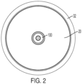
FIG. 2 is a top view of the induction heater ofFIG. 1 . -
FIG. 3 is a top perspective view of the resting surface and temperature detector of the induction heater ofFIG. 1 . -
FIG. 4 is a bottom perspective view of the resting surface and temperature detector of the induction heater ofFIG. 1 . -
FIG 5 . is a perspective cross-sectional view of the induction heater ofFIG. 1 . -
FIG. 6 is a side cross-sectional view of the induction heater ofFIG. 1 with a pan approaching the resting surface and temperature detector. -
FIG. 6a is a detail view of detail A ofFIG. 6 . -
FIG. 7 is the view ofFIG. 6 with the pan resting upon the temperature detector. -
FIG. 7a is a detail view of detail B ofFIG. 7 . -
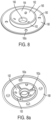
FIG. 8 is a top perspective view of the support disk of the temperature detector of the heaters ofFIGs. 1 and 1a . -
FIG. 8a is a bottom perspective view of the support disk ofFIG. 8 . -
FIG. 9 is a side cross-sectional view of the induction heater ofFIG. 1a , which includes a plurality of temperature detectors of the induction heater ofFIG. 1 . - Turning now to
FIGs. 1-9 , aninduction heating device 10 is provided. The induction heating device includes ahousing 24, aside wall 30, a restingsurface 20, aninduction coil 3000, and atemperature detector 100 that is disposed upon the restingsurface 20 and positioned such that thetemperature detector 100 is contacted by a bottom surface 1020 of apan 1010 when the pan is positioned within the heating device. This specification depicts two different shaped heating devices, a circular device (FIG. 1 ) that includes asingle temperature detector 100 disposed at the center of the restingsurface 20, and a rectangular device 2010 (FIG. 1a ) that includes threetemperature detectors 100 that are disposed at different positions upon theresting surface 2020, such as along a center line and consistently spaced from each other. As one of ordinary skill in the art will readily comprehend with reference to this disclosure and figures, induction heating devices with different shapes, sizes, and number oftemperature detectors 100 can be provided. - While this disclosure is drafted to specifically describe
devices 10 that are configured to hold cooked or heated food (or to heat food), this device may also be appropriate or modified to hold other non-food liquids or solids, such as chemicals, epoxies or glues that need to be maintained at a temperature above room temperature for a period of time. - In some embodiments, the
induction heating device 10 may be disposed within an aperture in a counter 1000 (FIG. 6 ) in a restaurant, banquet facility, or kitchen, other location where food is to be maintained heated for serving or cooking. In other embodiments, theinduction heating device 10 may be disposed within in a housing. - In some embodiments, the
induction coil 3000 may be disposed below the restingsurface 20 and in some embodiments theinduction coil 3000 may also be disposed within theside wall 30 of thedevice 10 so that the magnetic fields generated by theinduction coils 3000 are directed simultaneously to different portions of thepan 1010 for faster heating of the pan 1010 (and therefore the contents of the pan) and also for more uniform heating of the contents of the pan. Theinduction coil 3000 is operated to create a magnetic field that induces an eddy current in thepan 1010 when disposed thereon, as is known in the art. - The
temperature detector 100 may include a RTD 129 (resistance temperature detector) or it may be another form of temperature detector known in the art, which is configured to measure temperature and provide a signal to acontroller 4000 for feedback control purposes regarding operation of theinduction coil 3000. While RTDs are specifically discussed herein for the sake of brevity, the use of the term "RTD" when describing its use within the temperature detector applies to other temperature detection devices that are known in the art. Theinduction heating device 10 may include an input and display where the user can monitor the temperature of the device as well as input a desired temperature for the device. The input and display may communicate with the controller 400 and also include timers, information regarding the contents of the pan within the device. The input and display may be provided with the device, and also may communicate with a remote input display upon an app on a phone or tablet, a computer, and the like via a cellular signal, Wi-Fi, Bluetooth or via other known communication manners, which may operate via conventional or proprietary internet of things protocols. Thecontroller 4000 may additionally or alternatively communicate with a POS system and/or a restaurant network, automated recipe system, inventory system, or other databases or systems found within restaurant or other facility. - The
temperature detector 100 may include asupport 180 that supports a plurality of components thereon. In some embodiments, thesupport 180 may be fixed to the restingsurface 20, such as with a plurality of fasteners. Thesupport 180 may be disposed below the restingsurface 20, i.e. below thebottom surface 20b of the resting surface, which is opposite from theupper surface 20a that the pan rests upon. Thesupport 180 includes acentral pocket 182 and anouter resting surface 188. Thecentral pocket 182 receives thesecond housing 150 and a portion of thecentral portion 162 of the support disk 150 (FIG. 5 ). Thecentral pocket 182 includes acylindrical portion 183 and abottom wall 184. Thebottom wall 184 has an aperture through which thewire 109 of the RTD (discussed below) extends. Thebottom wall 184 may also receive aspring 190 thereupon that extends between the end cap 170 (when provided, otherwise the second housing 150) and applies an upward biasing force upon the second housing 150 (when provided through the end cap 170) that is transferred to thefirst housing 120 and thegrommet 140 to urge thefirst housing 120 andgrommet 140 upwardly with respect to the restingsurface 20 and thesupport disk 160, so that the temperature detector normally extends above thesupport disk 160 as depicted inFIGs. 6 and 6a . - The
outer resting surface 188 of thesupport 180 is a flat surface that extends outwardly from thecentral pocket 182. The outer resting surface extends parallel and below the restingsurface 20 and may be fixed to the restingsurface 20 with a plurality of fasteners that extend through a one or preferably multiple apertures in the outer resting surface 188 (and also extend through aligned holes in theouter support portion 168 of thesupport disk 160 and theledge 148 of the grommet 140 (each discussed below)). - The
temperature detector 100 further includes afirst housing 120, agrommet 140 and asecond housing 150. In some embodiments, thetemperature detector 100 further includes anend cap 170 that is connectable to thesecond housing 160, as discussed below. The temperature detector may further include asupport disk 160. - The
first housing 120 is best understood with reference toFIGs. 5 ,6a ,7a , and8 . Thefirst housing 120 receives and supports theRTD 129. In some embodiments, thefirst housing 120 includes atop surface 122 that with acentral portion 127 that faces upward and includes aledge portion 126 that extends outwardly from abody portion 124. Theledge portion 126 may be curved downwardly from the central portion and may have an outer circumferential portion 126b that extends in a downward direction. - The
first housing 120 may be established wherein the top to bottom cross-section of the first housing (i.e. a cross-section that extends through the longitudinal axis 2 of the first housing 120 (FIG. 8 )) is the same around the entire circumference of the first housing, other than the threads 124a that extend along thebody portion 124 and from the outer surface of thebody portion 124 in embodiments that include threads 124a. TheRTD 129 may be disposed within acavity 125 formed within the body portion and below the top surface and fixed in contact with an inner surface of thetop surface 122, such that theRTD 129 receives conduction heat transfer that extends through thetop surface 122. - The
RTD 129 may include awire 109 that extends through acavity 125 that extend within thebody portion 124 and out the bottom surface of thefirst housing 120. Thewire 109 may extend through the cavities through thesecond housing 150 and the cavity and hole in theend cap 170. Thewire 109 may further extend through a hole in thesupport 180 and ultimately be connected to acontroller 4000. In other embodiments, theRTD 129 may communicate with thecontroller 4000 wirelessly, such as via Wi-Fi, Bluetooth or via other known means of wireless communication. - The
controller 4000 receives a signal from theRTD 129 and uses feedback control to control the operation of the induction coils to control the temperature of the pan and ultimately the food within the pan as is well known in the art. - In some embodiments, the
cavity 125 may be filled with a material, such as an epoxy or other material to prevent foreign material from entering thecavity 125 and interfering with the operation of the RTD. The material that fills thecavity 125 may have a relatively low thermal conductivity (such as a thermal conductivity that is much lower than the thermal conductivity of the material, such as aluminum, that forms thetop surface 122 of the first housing 120) such that environmental heat, such as heat from the induction coils does not substantially communicate with the RTD during operation such that the output of the RTD is closely related to the heat flowing through thetop surface 122 to theRTD 129 from the pan and not from other heat sources. - The
first housing 120 is connected and extends within thesecond housing 150. Thesecond housing 150 may include aledge 153 at a top end thereof that has a diameter greater than an outer diameter of thebody 152. Similar to the first housing, thesecond housing 150 may be established such that a top to bottom cross-section of the second housing 150 (that extends through the longitudinal axis 2 of the second housing) is the same around the entire circumference of thesecond housing 150, other than the inner threads within the 155 through the second housing. Thesecond housing 150 includes top and bottom holes and an inner cavity/lumen that extends therethrough, which may be threaded. Thebody 124 of thefirst housing 120 through the top hole and threadably engages the second housing to fix the two components to each other. - In some embodiments, the
ledge 153 of the second housing includes a horizontal surface 153a and an upstanding surface 153b that is disposed at the edge portion of theledge 153. As best understood with reference toFIG. 5 , when thefirst housing 120 is connected to thesecond housing 150, the upstanding surface 153b of the second housing is aligned with the downwardly extending circumferential portion 126b, which receives a portion of thegrommet 140 therebetween. As shown inFIG. 5 , a void is formed inboard of the alignment between the upstanding surface 153b and the downwardly extending circumferential portion 126b that receives an inner circular surface of thegrommet 140 therein, which has a height that is greater than a space between the upstanding surface 153b and the downwardly extending circumferential portion 126b to securely retain thegrommet 140 with respect to the first andsecond housings - An
end cap 170 may be provided, which has aledge portion 172 and abody portion 174, with theledge portion 172 having a larger outer diameter than thebody portion 174. The end cap may have a cavity that extends through the end cap, through which the wire 109 (when provided) extends (which also extends through the cavity in thesecond housing 150. Thebody portion 174 may be threaded and the body portion may extend within a hole at the bottom of the second housing and threadably connect with thesecond housing 150 such that theledge portion 172 contacts the bottom end of thesecond housing 150 when assembled. In some embodiments, the outer diameter of theledge portion 172 of theend cap 170 may be larger than the outer diameter of the body 154 of the second housing, such that an inner flange of thesupport disk 160 rests upon theledge portion 172 when the temperature detector is assembled as shown inFIG. 5 . - As shown in
FIG. 8 , thefirst housing 120, thegrommet 140, thesecond housing 150, and theend cap 170 may be aligned along the same longitudinal axis 2 and may be connectable to each other via the threaded connections discussed above, with thegrommet 140 disposed between the ledges of the first and second housing, and in some embodiments with the portion of thegrommet 140 extending between the ledges being locally compressed by the first andsecond housings - The
support disk 160 is best shown inFIGs. 5 ,6a ,7a ,9 , and 9a. Thesupport disk 160 includes acenter portion 162 with an aperture therethrough (through which thesecond housing 150 extends), and anouter support portion 168. - The
outer support portion 168 defines the outer portion of the support disk and is flat and when assembled rests upon theouter resting surface 188 of thesupport 180. - The
center portion 162 includes an outercylindrical portion 163 that extends upwardly from theouter resting portion 168 and an inverseconical portion 164 that extends downwardly toward a central aperture. The inverse conical portion includes an upper facing surface that has a straight cross-section (FIG. 5 ), and is projected about its central longitudinal axis (2) a full 360 degrees, to establish the inverse of a cone aroundcenter portion 162. In other embodiments, thecenter portion 162 may define a curved surface (along the entire surface or a portion of the surface) that extends downwardly toward the central aperture which may also extend a full 360 degrees around the central longitudinal axis (2). - In some embodiments, the
top surface 165 of the center portion is disposed at a similar (or the same) height as thetop surface 20a of the restingsurface 20, which allows thearcuate portion 142 of thegrommet 140 to be compressed such the grommet does not extend above theledge 147 of the grommet when thegrommet 140 andfirst housing 120 are urged downwardly by a pan resting thereon (FIG. 7a ). - In some embodiments, the
center portion 162 forms a central aperture, that is defined by aninner flange 166 that extends within thepocket 182 of thesupport 180 and in some embodiments contacts theend cap 170. As shown inFIG. 5 , the second housing extends within theinner flange 166 of the center portion, which supports thesecond housing 150. - The
grommet 140 is best shown inFIGs. 5 ,6a ,7a , and8 . The grommet may be made from an elastomeric material, such as rubber or elastomeric polymers. Thegrommet 140 includes anarcuate portion 142 that defines a central opening, a cantileveredportion 147, and aledge 147. Theledge 148 extends generally parallel to the cantileveredportion 147, with a space disposed therebetween. As shown inFIG. 5 , the restingsurface 20 extends within the space, such that the cantileveredportion 147 rests upon thetop surface 20a of the restingsurface 20 and thebottom surface 20b rests upon theledge 148. - The
arcuate portion 142 is biased upwardly by the spring 190 (via the second housing 150) such that it normally extends to an elevation above thetop surface 20a of the restingportion 20. In some embodiments, the curvature of thegrommet 140 may also contribute to the upward biasing force upon thefirst housing 120. Thearcuate portion 142 extends from theledge 147 in a cantilevered manner toward the center aperture. As discussed above a portion of thearcuate portion 142 of thegrommet 140 is disposed between the upstanding surface 153b of thesecond housing 150 and the downwardly extending circumferential portion 126b of thefirst housing 120, such that a downward force applied to the first housing 120 (by the pan being disposed thereon) causes thegrommet 140 to be urged downwardly, which elastically deforms the grommet such that itsarcuate portion 142 extends below theledge 147 is thefirst housing 120 is forced downward. Downward motion of thefirst housing 120 similar causes downward motion of the second housing 150 (and theend cap 170 when provided) against the biasing force of thespring 190. As the arcuate portion is deformed it approaches and may contact thecenter portion 162 of thesupport disk 160. - Turning now to
FIGs. 6-7a , the operation of thetemperature detector 100 is best understood. As shown inFIGs. 6 and 6a , thearcuate portion 142 of the 140 and thefirst housing 120 normally extend above thetop surface 20a of the restingsurface 20 and above theledge 147 of thegrommet 140. As shown inFIGs. 7 and 7a , when apan 1010 is positioned upon thefirst housing 120 andgrommet 140 are pushed downward by the force/weight of thepan 1010, which ensures that thetop surface 122 of thefirst housing 120 makes good contact with the bottom surface of thepan 1010, which ensures that the RTD receives a heat flux through thetop surface 122 that is representative of the heat of thepan 1010. When thepan 1010 is removed, the biasing force of thespring 190 urges thefirst housing 120 and the grommet 140 (and thesecond housing 150, which is fixed to the first housing 120) upward to return to the orientation ofFIGs. 6 and 6a . - While the preferred embodiments of the disclosed have been described, it should be understood that the invention is not so limited and modifications may be made without departing from the disclosure. The scope of the disclosure is defined by the appended claims, and all devices that come within the meaning of the claims, either literally or by equivalence, are intended to be embraced therein.
- Described herein is a temperature detector configured to be disposed in an aperture in a resting surface of an induction heating system. The temperature detector comprises an RTD and associated wiring, a first housing that receives the RTD, and a grommet disposed around the first housing. The grommet includes an arcuate portion. The arcuate portion may be arranged to engage with the resting surface when, in use, the temperature detector is disposed in the aperture in the resting surface. The arcuate portion may surround the temperature detector to provide an outwardly extending flange, which may be annular, for example circularly annular.
- This grommet may be configured to allow movement of the temperature detector upward and/or downward relative to the resting surface, for example resilient movement. This may allow the temperature detector to be depressed into the resting surface, for example by a pan being positioned on the resting surface for heating. When it is depressed in this way, the arcuate portion may be biased in a direction upwardly from the resting surface. This temperature detector further comprises a cylindrical second housing that supports and receives a portion of the first housing therewith and through a first end of the second housing, comprises a central opening through which the first housing extends, wherein the central opening defines a inner circular surface that is disposed between the first and second housings.
Claims (13)
- A system comprising a temperature detector (100) and an induction heating system, the induction heating system comprising a resting surface (20) wherein a pan (1010) is to be disposed for heating by the induction heating system on the resting surface (20), for example wherein the temperature detector (100) is disposed upon the resting surface (20) such that the pan disposed for heating on the resting surface (20) contacts the temperature detector (100), for example wherein the induction heating system comprises an induction coil (3000),
the temperature detector (100) is configured to be disposed in an aperture in the resting surface of the induction heating system, the temperature detector comprising:an RTD (129) and associated wiring (109), a first housing (120) that receives the RTD (129), and a grommet (140) disposed around the first housing (120),the temperature detector (100) further comprises a cylindrical second housing (150) that supports and receives a portion of the first housing (120) therewith and through a first end of the second housing (150),wherein the grommet (140) includes an arcuate portion (142) arranged such that when, in use, the temperature detector (100) is disposed in the aperture in the resting surface (20) the arcuate portion (142) engages with the resting surface (20), wherein the arcuate portion (142) is biased in a direction upwardly from the resting surface (20), the arcuate portion (142) comprises a central opening through which the first housing (120) extends, wherein the central opening defines a inner circular surface that is disposed between the first and second housings (120, 150),the grommet (140) further comprises a ledge (148) and a cantilevered portion (147) wherein the arcuate portion (142) extends from the cantilevered portion (147), and the arcuate portion (142) defines the central opening, wherein the ledge (148) extends generally parallel to the cantilevered portion (147) with a space disposed therebetween, wherein the resting surface extends within the space such that the cantilevered portion (147) rests upon a top surface (20a) of the resting surface 20 and the bottom surface (20b) rests upon the ledge (148). - The system of claim 1, further comprising an end cap (170) that extends into the second housing (150) through a second end of the second housing (150), wherein the end cap (170) contacts the inner surface of the second housing (150).
- The system of claim 2, wherein the inner surface of the second housing (150) is threaded along at least a portion of its length, and wherein the first housing (120) and the second housing (150) make a threaded connection, and wherein the end cap (170) makes a threaded connection with the second housing (150).
- The system of any one of the preceding claims wherein the associated wiring (109) from the RTD (129) extends through the first housing (120), the central opening in the grommet (140), and the second housing (150).
- The system of any preceding claim, wherein the grommet (140) is circular and the ledge (148), cantilevered portion (147), and the arcuate portion (142) each extend around the circumference of the circular grommet (140).
- The system of any preceding claim further comprising a support disk (160) that is disposed below the ledge (148), the support disk (160) includes a center portion with an aperture though which the second housing (150) extends, the center portion of the support disk (160) has an inverse conical portion (164) with a side wall that extends downwardly toward the aperture, wherein the inverse conical portion (164) is disposed below the arcuate portion (142) of the grommet (140).
- The system of claim 6, wherein the first housing (120) is aluminium and/or the grommet (140) is an elastomeric material.
- The system of any preceding claim, wherein the resting surface (20) is circular and includes a center aperture through which the temperature detector (100) extends, further comprising a side wall that contacts an outer circumferential sidewall of the resting surface (20) and extends above a top surface of the resting surface (20).
- The system of any preceding claim, wherein the temperature detector (100) comprises a plurality of temperature detectors (100), wherein the resting surface (20) is rectangular and includes a plurality of spaced apertures and each of the plurality of temperature detectors (100) extends through a respective corresponding one of the plurality of spaced apertures, the temperature detector (100) optionally further comprising a side wall that contacts and outer surface of the resting surface (20) and extends above a top surface of the resting surface (20).
- The system of any preceding claim wherein the grommet (140) further comprises a ledge (148) and a cantilevered portion (147), wherein the arcuate portion (142) extends from the cantilevered portion (147), the arcuate portion (142) defines the central opening, and wherein a portion of the resting surface (20) is disposed between the cantilevered portion (147) and the ledge (148).
- The system of claim 10 wherein the arcuate portion (142) of the grommet (140) is configured so that when the grommet (140) is urged downwardly the first housing (120) and the second housing (150) are also urged downwardly, for example when a pan (1010) is positioned upon the first housing (120).
- The system of claim 11 wherein the temperature detector (100) comprises a support disk (160) that is disposed below the ledge (148), the support disk (160) includes a center portion with an aperture though which the second housing (150) extends, the center portion an inverse conical portion (164) with a side wall that extends downwardly toward the aperture, wherein the inverse conical portion (164) is disposed below the arcuate portion (142) of the grommet (140) wherein the arcuate portion (142) of the grommet (140) contacts the center portion of the support disk (160) when urged downwardly when the pan is positioned upon the first housing (120).
- The system of claim 11, wherein the second housing (150) and first housing (120) are urged upwardly by a spring (190) disposed below the second housing (150) and wherein the first and second housings (150) are urged downwardly against the upward urging force of the spring (190) when a pan (1010) is disposed upon the first housing (120).
Applications Claiming Priority (1)
| Application Number | Priority Date | Filing Date | Title |
|---|---|---|---|
| US202063036727P | 2020-06-09 | 2020-06-09 |
Publications (3)
| Publication Number | Publication Date |
|---|---|
| EP3922970A1 EP3922970A1 (en) | 2021-12-15 |
| EP3922970B1 true EP3922970B1 (en) | 2024-08-07 |
| EP3922970C0 EP3922970C0 (en) | 2024-08-07 |
Family
ID=76374945
Family Applications (1)
| Application Number | Title | Priority Date | Filing Date |
|---|---|---|---|
| EP21178646.2A Active EP3922970B1 (en) | 2020-06-09 | 2021-06-09 | Temperature detector for induction heating system |
Country Status (3)
| Country | Link |
|---|---|
| US (1) | US20210385915A1 (en) |
| EP (1) | EP3922970B1 (en) |
| ES (1) | ES2993336T3 (en) |
Families Citing this family (1)
| Publication number | Priority date | Publication date | Assignee | Title |
|---|---|---|---|---|
| US20230301311A1 (en) * | 2022-03-25 | 2023-09-28 | Haier Us Appliance Solutions, Inc. | Bakeware assembly with temperature probe adapter |
Family Cites Families (8)
| Publication number | Priority date | Publication date | Assignee | Title |
|---|---|---|---|---|
| US3051813A (en) * | 1960-08-24 | 1962-08-28 | Gen Electric | Temperature control systems |
| GB2115550B (en) * | 1982-02-22 | 1985-06-26 | Walton Eng Co Ltd | Improvements relating to housings for sensing elements |
| AU2015281781B2 (en) * | 2014-06-23 | 2021-02-25 | Breville Pty Limited | Multi cooker |
| US10426292B2 (en) * | 2016-04-28 | 2019-10-01 | The Vollrath Company, L.L.C. | Temperature regulation device |
| US20190357319A1 (en) * | 2018-05-18 | 2019-11-21 | Hatco Corporation | Sensor system for temperature-regulating appliance |
| CN112312809A (en) * | 2018-06-29 | 2021-02-02 | 布瑞威利私人有限公司 | Temperature monitoring and control systems for kitchen installations |
| CN208671084U (en) * | 2018-08-16 | 2019-03-29 | 佛山市顺德区美的电热电器制造有限公司 | Temperature sensor and heating instrument assemblies |
| US11627643B2 (en) * | 2019-03-12 | 2023-04-11 | Bonbowl, LLC | Induction cooktop system |
-
2021
- 2021-06-08 US US17/341,878 patent/US20210385915A1/en active Pending
- 2021-06-09 ES ES21178646T patent/ES2993336T3/en active Active
- 2021-06-09 EP EP21178646.2A patent/EP3922970B1/en active Active
Also Published As
| Publication number | Publication date |
|---|---|
| EP3922970A1 (en) | 2021-12-15 |
| US20210385915A1 (en) | 2021-12-09 |
| EP3922970C0 (en) | 2024-08-07 |
| ES2993336T3 (en) | 2024-12-27 |
Similar Documents
| Publication | Publication Date | Title |
|---|---|---|
| US11022321B1 (en) | Cooking appliance accessory and method of use | |
| RU2689410C2 (en) | Multi cooktop | |
| US20160316968A1 (en) | Cooking Container Provided with a Temperature Sensor and Means for Identifying a Cooking Area | |
| US20170245673A1 (en) | Circulator apparatus | |
| EP3922970A1 (en) | Temperature detector for induction heating system | |
| CN110613311A (en) | Cooking utensil and outer pot | |
| US10827565B2 (en) | Induction cooktop system with a temperature sensor | |
| US20180299135A1 (en) | Cooking appliance and knob assembly | |
| US3303327A (en) | Electrical heater having a snap-in base plate | |
| US7326885B2 (en) | Hot plate with stainless steel top | |
| CN113116188A (en) | Kitchen appliance with a weighing device | |
| CN212234118U (en) | Cooking utensil | |
| JP2014216246A (en) | Electromagnetic cooker | |
| US20080210100A1 (en) | Electric Cooking Appliance Comprising a Removable Bowl | |
| JP7007360B2 (en) | Induction heaters and dispensers | |
| CN209235709U (en) | Induction Pots and Induction Cookware | |
| CN209153163U (en) | Cooking utensil | |
| CN218606133U (en) | Food container | |
| CN211212583U (en) | cookware | |
| CN214048478U (en) | Coil disc subassembly and have its cooking utensil | |
| CN209404432U (en) | cooking utensils | |
| CN210842662U (en) | Cooking utensil | |
| CN110754913B (en) | Cooking utensil | |
| CN210121059U (en) | Cooking utensil | |
| CN216090039U (en) | Cooking utensil and pot body thereof |
Legal Events
| Date | Code | Title | Description |
|---|---|---|---|
| PUAI | Public reference made under article 153(3) epc to a published international application that has entered the european phase |
Free format text: ORIGINAL CODE: 0009012 |
|
| STAA | Information on the status of an ep patent application or granted ep patent |
Free format text: STATUS: THE APPLICATION HAS BEEN PUBLISHED |
|
| AK | Designated contracting states |
Kind code of ref document: A1 Designated state(s): AL AT BE BG CH CY CZ DE DK EE ES FI FR GB GR HR HU IE IS IT LI LT LU LV MC MK MT NL NO PL PT RO RS SE SI SK SM TR |
|
| B565 | Issuance of search results under rule 164(2) epc |
Effective date: 20211112 |
|
| STAA | Information on the status of an ep patent application or granted ep patent |
Free format text: STATUS: REQUEST FOR EXAMINATION WAS MADE |
|
| 17P | Request for examination filed |
Effective date: 20220615 |
|
| RBV | Designated contracting states (corrected) |
Designated state(s): AL AT BE BG CH CY CZ DE DK EE ES FI FR GB GR HR HU IE IS IT LI LT LU LV MC MK MT NL NO PL PT RO RS SE SI SK SM TR |
|
| P01 | Opt-out of the competence of the unified patent court (upc) registered |
Effective date: 20230526 |
|
| GRAP | Despatch of communication of intention to grant a patent |
Free format text: ORIGINAL CODE: EPIDOSNIGR1 |
|
| STAA | Information on the status of an ep patent application or granted ep patent |
Free format text: STATUS: GRANT OF PATENT IS INTENDED |
|
| INTG | Intention to grant announced |
Effective date: 20240123 |
|
| GRAS | Grant fee paid |
Free format text: ORIGINAL CODE: EPIDOSNIGR3 |
|
| GRAA | (expected) grant |
Free format text: ORIGINAL CODE: 0009210 |
|
| STAA | Information on the status of an ep patent application or granted ep patent |
Free format text: STATUS: THE PATENT HAS BEEN GRANTED |
|
| AK | Designated contracting states |
Kind code of ref document: B1 Designated state(s): AL AT BE BG CH CY CZ DE DK EE ES FI FR GB GR HR HU IE IS IT LI LT LU LV MC MK MT NL NO PL PT RO RS SE SI SK SM TR |
|
| REG | Reference to a national code |
Ref country code: GB Ref legal event code: FG4D |
|
| REG | Reference to a national code |
Ref country code: CH Ref legal event code: EP |
|
| REG | Reference to a national code |
Ref country code: IE Ref legal event code: FG4D |
|
| REG | Reference to a national code |
Ref country code: DE Ref legal event code: R096 Ref document number: 602021016691 Country of ref document: DE |
|
| U01 | Request for unitary effect filed |
Effective date: 20240906 |
|
| P04 | Withdrawal of opt-out of the competence of the unified patent court (upc) registered |
Free format text: CASE NUMBER: APP_52277/2024 Effective date: 20240917 |
|
| U07 | Unitary effect registered |
Designated state(s): AT BE BG DE DK EE FI FR IT LT LU LV MT NL PT RO SE SI Effective date: 20240920 |
|
| REG | Reference to a national code |
Ref country code: ES Ref legal event code: FG2A Ref document number: 2993336 Country of ref document: ES Kind code of ref document: T3 Effective date: 20241227 |
|
| P05 | Withdrawal of opt-out of the competence of the unified patent court (upc) changed |
Free format text: CASE NUMBER: APP_52277/2024 Effective date: 20240920 |
|
| PG25 | Lapsed in a contracting state [announced via postgrant information from national office to epo] |
Ref country code: NO Free format text: LAPSE BECAUSE OF FAILURE TO SUBMIT A TRANSLATION OF THE DESCRIPTION OR TO PAY THE FEE WITHIN THE PRESCRIBED TIME-LIMIT Effective date: 20241107 |
|
| PG25 | Lapsed in a contracting state [announced via postgrant information from national office to epo] |
Ref country code: PL Free format text: LAPSE BECAUSE OF FAILURE TO SUBMIT A TRANSLATION OF THE DESCRIPTION OR TO PAY THE FEE WITHIN THE PRESCRIBED TIME-LIMIT Effective date: 20240807 Ref country code: GR Free format text: LAPSE BECAUSE OF FAILURE TO SUBMIT A TRANSLATION OF THE DESCRIPTION OR TO PAY THE FEE WITHIN THE PRESCRIBED TIME-LIMIT Effective date: 20241108 |
|
| PG25 | Lapsed in a contracting state [announced via postgrant information from national office to epo] |
Ref country code: IS Free format text: LAPSE BECAUSE OF FAILURE TO SUBMIT A TRANSLATION OF THE DESCRIPTION OR TO PAY THE FEE WITHIN THE PRESCRIBED TIME-LIMIT Effective date: 20241207 |
|
| PG25 | Lapsed in a contracting state [announced via postgrant information from national office to epo] |
Ref country code: HR Free format text: LAPSE BECAUSE OF FAILURE TO SUBMIT A TRANSLATION OF THE DESCRIPTION OR TO PAY THE FEE WITHIN THE PRESCRIBED TIME-LIMIT Effective date: 20240807 |
|
| PG25 | Lapsed in a contracting state [announced via postgrant information from national office to epo] |
Ref country code: RS Free format text: LAPSE BECAUSE OF FAILURE TO SUBMIT A TRANSLATION OF THE DESCRIPTION OR TO PAY THE FEE WITHIN THE PRESCRIBED TIME-LIMIT Effective date: 20241107 |
|
| PG25 | Lapsed in a contracting state [announced via postgrant information from national office to epo] |
Ref country code: RS Free format text: LAPSE BECAUSE OF FAILURE TO SUBMIT A TRANSLATION OF THE DESCRIPTION OR TO PAY THE FEE WITHIN THE PRESCRIBED TIME-LIMIT Effective date: 20241107 Ref country code: PL Free format text: LAPSE BECAUSE OF FAILURE TO SUBMIT A TRANSLATION OF THE DESCRIPTION OR TO PAY THE FEE WITHIN THE PRESCRIBED TIME-LIMIT Effective date: 20240807 Ref country code: NO Free format text: LAPSE BECAUSE OF FAILURE TO SUBMIT A TRANSLATION OF THE DESCRIPTION OR TO PAY THE FEE WITHIN THE PRESCRIBED TIME-LIMIT Effective date: 20241107 Ref country code: IS Free format text: LAPSE BECAUSE OF FAILURE TO SUBMIT A TRANSLATION OF THE DESCRIPTION OR TO PAY THE FEE WITHIN THE PRESCRIBED TIME-LIMIT Effective date: 20241207 Ref country code: HR Free format text: LAPSE BECAUSE OF FAILURE TO SUBMIT A TRANSLATION OF THE DESCRIPTION OR TO PAY THE FEE WITHIN THE PRESCRIBED TIME-LIMIT Effective date: 20240807 Ref country code: GR Free format text: LAPSE BECAUSE OF FAILURE TO SUBMIT A TRANSLATION OF THE DESCRIPTION OR TO PAY THE FEE WITHIN THE PRESCRIBED TIME-LIMIT Effective date: 20241108 |
|
| PG25 | Lapsed in a contracting state [announced via postgrant information from national office to epo] |
Ref country code: SM Free format text: LAPSE BECAUSE OF FAILURE TO SUBMIT A TRANSLATION OF THE DESCRIPTION OR TO PAY THE FEE WITHIN THE PRESCRIBED TIME-LIMIT Effective date: 20240807 |
|
| PG25 | Lapsed in a contracting state [announced via postgrant information from national office to epo] |
Ref country code: CZ Free format text: LAPSE BECAUSE OF FAILURE TO SUBMIT A TRANSLATION OF THE DESCRIPTION OR TO PAY THE FEE WITHIN THE PRESCRIBED TIME-LIMIT Effective date: 20240807 |
|
| PG25 | Lapsed in a contracting state [announced via postgrant information from national office to epo] |
Ref country code: SK Free format text: LAPSE BECAUSE OF FAILURE TO SUBMIT A TRANSLATION OF THE DESCRIPTION OR TO PAY THE FEE WITHIN THE PRESCRIBED TIME-LIMIT Effective date: 20240807 |
|
| PLBE | No opposition filed within time limit |
Free format text: ORIGINAL CODE: 0009261 |
|
| STAA | Information on the status of an ep patent application or granted ep patent |
Free format text: STATUS: NO OPPOSITION FILED WITHIN TIME LIMIT |
|
| PGFP | Annual fee paid to national office [announced via postgrant information from national office to epo] |
Ref country code: GB Payment date: 20250627 Year of fee payment: 5 |
|
| 26N | No opposition filed |
Effective date: 20250508 |
|
| U20 | Renewal fee for the european patent with unitary effect paid |
Year of fee payment: 5 Effective date: 20250628 |
|
| PGFP | Annual fee paid to national office [announced via postgrant information from national office to epo] |
Ref country code: ES Payment date: 20250701 Year of fee payment: 5 |
|
| REG | Reference to a national code |
Ref country code: CH Ref legal event code: H13 Free format text: ST27 STATUS EVENT CODE: U-0-0-H10-H13 (AS PROVIDED BY THE NATIONAL OFFICE) Effective date: 20260127 |
|
| PG25 | Lapsed in a contracting state [announced via postgrant information from national office to epo] |
Ref country code: MC Free format text: LAPSE BECAUSE OF FAILURE TO SUBMIT A TRANSLATION OF THE DESCRIPTION OR TO PAY THE FEE WITHIN THE PRESCRIBED TIME-LIMIT Effective date: 20240807 |
|
| PG25 | Lapsed in a contracting state [announced via postgrant information from national office to epo] |
Ref country code: IE Free format text: LAPSE BECAUSE OF NON-PAYMENT OF DUE FEES Effective date: 20250609 |
|
| PG25 | Lapsed in a contracting state [announced via postgrant information from national office to epo] |
Ref country code: CH Free format text: LAPSE BECAUSE OF NON-PAYMENT OF DUE FEES Effective date: 20250630 |