EP3922954A1 - System and method for determining angular position in rotating machines - Google Patents
System and method for determining angular position in rotating machines Download PDFInfo
- Publication number
- EP3922954A1 EP3922954A1 EP21175542.6A EP21175542A EP3922954A1 EP 3922954 A1 EP3922954 A1 EP 3922954A1 EP 21175542 A EP21175542 A EP 21175542A EP 3922954 A1 EP3922954 A1 EP 3922954A1
- Authority
- EP
- European Patent Office
- Prior art keywords
- track
- sensor
- output
- printed circuit
- circuit card
- Prior art date
- Legal status (The legal status is an assumption and is not a legal conclusion. Google has not performed a legal analysis and makes no representation as to the accuracy of the status listed.)
- Granted
Links
Images



Classifications
-
- G—PHYSICS
- G01—MEASURING; TESTING
- G01D—MEASURING NOT SPECIALLY ADAPTED FOR A SPECIFIC VARIABLE; ARRANGEMENTS FOR MEASURING TWO OR MORE VARIABLES NOT COVERED IN A SINGLE OTHER SUBCLASS; TARIFF METERING APPARATUS; MEASURING OR TESTING NOT OTHERWISE PROVIDED FOR
- G01D5/00—Mechanical means for transferring the output of a sensing member; Means for converting the output of a sensing member to another variable where the form or nature of the sensing member does not constrain the means for converting; Transducers not specially adapted for a specific variable
- G01D5/12—Mechanical means for transferring the output of a sensing member; Means for converting the output of a sensing member to another variable where the form or nature of the sensing member does not constrain the means for converting; Transducers not specially adapted for a specific variable using electric or magnetic means
- G01D5/244—Mechanical means for transferring the output of a sensing member; Means for converting the output of a sensing member to another variable where the form or nature of the sensing member does not constrain the means for converting; Transducers not specially adapted for a specific variable using electric or magnetic means influencing characteristics of pulses or pulse trains; generating pulses or pulse trains
- G01D5/245—Mechanical means for transferring the output of a sensing member; Means for converting the output of a sensing member to another variable where the form or nature of the sensing member does not constrain the means for converting; Transducers not specially adapted for a specific variable using electric or magnetic means influencing characteristics of pulses or pulse trains; generating pulses or pulse trains using a variable number of pulses in a train
- G01D5/2451—Incremental encoders
-
- G—PHYSICS
- G01—MEASURING; TESTING
- G01D—MEASURING NOT SPECIALLY ADAPTED FOR A SPECIFIC VARIABLE; ARRANGEMENTS FOR MEASURING TWO OR MORE VARIABLES NOT COVERED IN A SINGLE OTHER SUBCLASS; TARIFF METERING APPARATUS; MEASURING OR TESTING NOT OTHERWISE PROVIDED FOR
- G01D5/00—Mechanical means for transferring the output of a sensing member; Means for converting the output of a sensing member to another variable where the form or nature of the sensing member does not constrain the means for converting; Transducers not specially adapted for a specific variable
- G01D5/12—Mechanical means for transferring the output of a sensing member; Means for converting the output of a sensing member to another variable where the form or nature of the sensing member does not constrain the means for converting; Transducers not specially adapted for a specific variable using electric or magnetic means
- G01D5/244—Mechanical means for transferring the output of a sensing member; Means for converting the output of a sensing member to another variable where the form or nature of the sensing member does not constrain the means for converting; Transducers not specially adapted for a specific variable using electric or magnetic means influencing characteristics of pulses or pulse trains; generating pulses or pulse trains
- G01D5/245—Mechanical means for transferring the output of a sensing member; Means for converting the output of a sensing member to another variable where the form or nature of the sensing member does not constrain the means for converting; Transducers not specially adapted for a specific variable using electric or magnetic means influencing characteristics of pulses or pulse trains; generating pulses or pulse trains using a variable number of pulses in a train
- G01D5/2454—Encoders incorporating incremental and absolute signals
-
- G—PHYSICS
- G01—MEASURING; TESTING
- G01D—MEASURING NOT SPECIALLY ADAPTED FOR A SPECIFIC VARIABLE; ARRANGEMENTS FOR MEASURING TWO OR MORE VARIABLES NOT COVERED IN A SINGLE OTHER SUBCLASS; TARIFF METERING APPARATUS; MEASURING OR TESTING NOT OTHERWISE PROVIDED FOR
- G01D5/00—Mechanical means for transferring the output of a sensing member; Means for converting the output of a sensing member to another variable where the form or nature of the sensing member does not constrain the means for converting; Transducers not specially adapted for a specific variable
- G01D5/12—Mechanical means for transferring the output of a sensing member; Means for converting the output of a sensing member to another variable where the form or nature of the sensing member does not constrain the means for converting; Transducers not specially adapted for a specific variable using electric or magnetic means
- G01D5/14—Mechanical means for transferring the output of a sensing member; Means for converting the output of a sensing member to another variable where the form or nature of the sensing member does not constrain the means for converting; Transducers not specially adapted for a specific variable using electric or magnetic means influencing the magnitude of a current or voltage
- G01D5/142—Mechanical means for transferring the output of a sensing member; Means for converting the output of a sensing member to another variable where the form or nature of the sensing member does not constrain the means for converting; Transducers not specially adapted for a specific variable using electric or magnetic means influencing the magnitude of a current or voltage using Hall-effect devices
- G01D5/145—Mechanical means for transferring the output of a sensing member; Means for converting the output of a sensing member to another variable where the form or nature of the sensing member does not constrain the means for converting; Transducers not specially adapted for a specific variable using electric or magnetic means influencing the magnitude of a current or voltage using Hall-effect devices influenced by the relative movement between the Hall device and magnetic fields
-
- G—PHYSICS
- G01—MEASURING; TESTING
- G01D—MEASURING NOT SPECIALLY ADAPTED FOR A SPECIFIC VARIABLE; ARRANGEMENTS FOR MEASURING TWO OR MORE VARIABLES NOT COVERED IN A SINGLE OTHER SUBCLASS; TARIFF METERING APPARATUS; MEASURING OR TESTING NOT OTHERWISE PROVIDED FOR
- G01D2205/00—Indexing scheme relating to details of means for transferring or converting the output of a sensing member
- G01D2205/70—Position sensors comprising a moving target with particular shapes, e.g. of soft magnetic targets
- G01D2205/77—Specific profiles
-
- G—PHYSICS
- G01—MEASURING; TESTING
- G01D—MEASURING NOT SPECIALLY ADAPTED FOR A SPECIFIC VARIABLE; ARRANGEMENTS FOR MEASURING TWO OR MORE VARIABLES NOT COVERED IN A SINGLE OTHER SUBCLASS; TARIFF METERING APPARATUS; MEASURING OR TESTING NOT OTHERWISE PROVIDED FOR
- G01D2205/00—Indexing scheme relating to details of means for transferring or converting the output of a sensing member
- G01D2205/70—Position sensors comprising a moving target with particular shapes, e.g. of soft magnetic targets
- G01D2205/77—Specific profiles
- G01D2205/773—Spiral profiles
-
- G—PHYSICS
- G01—MEASURING; TESTING
- G01D—MEASURING NOT SPECIALLY ADAPTED FOR A SPECIFIC VARIABLE; ARRANGEMENTS FOR MEASURING TWO OR MORE VARIABLES NOT COVERED IN A SINGLE OTHER SUBCLASS; TARIFF METERING APPARATUS; MEASURING OR TESTING NOT OTHERWISE PROVIDED FOR
- G01D5/00—Mechanical means for transferring the output of a sensing member; Means for converting the output of a sensing member to another variable where the form or nature of the sensing member does not constrain the means for converting; Transducers not specially adapted for a specific variable
- G01D5/12—Mechanical means for transferring the output of a sensing member; Means for converting the output of a sensing member to another variable where the form or nature of the sensing member does not constrain the means for converting; Transducers not specially adapted for a specific variable using electric or magnetic means
- G01D5/14—Mechanical means for transferring the output of a sensing member; Means for converting the output of a sensing member to another variable where the form or nature of the sensing member does not constrain the means for converting; Transducers not specially adapted for a specific variable using electric or magnetic means influencing the magnitude of a current or voltage
- G01D5/142—Mechanical means for transferring the output of a sensing member; Means for converting the output of a sensing member to another variable where the form or nature of the sensing member does not constrain the means for converting; Transducers not specially adapted for a specific variable using electric or magnetic means influencing the magnitude of a current or voltage using Hall-effect devices
- G01D5/147—Mechanical means for transferring the output of a sensing member; Means for converting the output of a sensing member to another variable where the form or nature of the sensing member does not constrain the means for converting; Transducers not specially adapted for a specific variable using electric or magnetic means influencing the magnitude of a current or voltage using Hall-effect devices influenced by the movement of a third element, the position of Hall device and the source of magnetic field being fixed in respect to each other
Definitions
- the present invention generally relates to determining angular position in rotating machines, and more particularly relates to determining absolute angular position using a device having features with a periodicity that generates a desired output for control purposes.
- angular position may be used to derive speed.
- electronically commutated motors may rely on a determination of angular position of the rotor to provide information to commutate the motor.
- Typical DC motor commutation may rely on some form of hall sensor or optical position encoder to provide the position information. In a number of applications these options may be relatively costly and may be complicated to implement.
- a gear toothed wheel has been used in combination with a gear tooth sensor.
- This alternative is relatively straight-forward to implement and generally has a relatively low cost.
- Output from this type of sensor corresponds with the number of gear teeth passing in front of it.
- the sensor's output may increase and when the gear tooth or magnetic pole moves away from the sensor, the output may decrease. This repeats at every tooth resulting in a sinusoidal output.
- These sensors are generally designed to work with certain defined gear tooth pitches. In applications that require a large number of gear teeth, the size of the resulting gear often requires redesign of the motor and as a result, implementing this alternative may become impractical.
- a machine with a rotor has a repeating sequence of segments that are arranged in a track.
- the track is disposed at a diameter around a shaft of the rotor and rotates about an axis with the rotor.
- a sensor is positioned to face the track and is fixed relative to the stator.
- the track and the sensor may be disposed in a common plane and face each other. The sensor generates an output that is decoupled from the diameter of the track and is related to the repeating sequence of segments.
- a method for determining angular position includes arranging a repeating sequence of segments in a track disposed at a diameter around a shaft.
- a sensor is positioned facing the track so that the track and the sensor rotate relative to each other about an axis.
- the track and the sensor are mounted to face each other.
- the sensor generates an output that is decoupled from the diameter of the track and is related to the repeating sequence of segments
- a system for determining angular position of an electrical machine includes a rotor with a shaft and a track having a repeating sequence of segments arranged around the shaft at a diameter of the track.
- the rotor rotates about an axis.
- a printed circuit board assembly does not move relative to a stator, encircles the shaft, and includes driver electronics of the electrical machine.
- the printed circuit board assembly includes a sensor facing the track, with the sensor and track facing each other, which may be in directions that are parallel to the axis. The sensor generates an output that is decoupled from the diameter of the track and is related to the repeating sequence of segments.
- an output such as a sine and cosine waveform pair is desirable, such as to indicate the angular position of a rotating machine.
- a sine and cosine output pair provides a unique indication of any angular position of the machine.
- An annular track includes a feature shaped to produce the desired output and is carried with a part of the machine, such as around the shaft of the rotor. At least one sensor is carried with another part of the machine, such as its stator, and is positioned to generate a signal responsive to the moving track.
- the track has a feature that repeats in intervals at a periodicity.
- the diameter of the track is decoupled from the output because the desired periodicity may be produced at any of various sized diameters around the shaft by changing the shape of the track's feature.
- the sensor(s) may be disposed on a common printed circuit board with other control components such as the drive electronics for the machine. In embodiments, this enables generating a signal for commutation where the shape of the track may be altered to match various desired numbers of pole pairs, without a need to change the diameter and packaging space needed.
- the machine 20 generally includes a pair of relatively rotatable components/bodies in the form of a rotor 22 and a stator 24 in this embodiment.
- the rotor 22 and the stator 24 are carried in a housing 26.
- the rotor 22 includes a shaft 28 supported in the housing 26 by bearing assemblies 30, 32 to rotate about an axis 33 of rotation.
- a ring 34 is carried by the rotor 22 to move therewith and includes a track 36. In other embodiments, the ring 34 may be formed as a disk or other shape to carry the track 36.
- the track 36 is generally annular in shape, surrounds the shaft 28, may be continuous or stepped, and includes a feature in the form of a shaped, repeating pattern to produce a desired output.
- the stator 24 may be fixed to the housing 26 along with a printed circuit board assembly (PCBA) 38, or in some embodiments may move relative thereto.
- the PCBA 38 includes a printed circuit board 39 and electronic elements 40 for control purposes, which in the current embodiment includes circuit components of the motor drive electronics 41 for the machine 20.
- the PCBA 38 also carries at least one sensor 46 positioned adjacent to and facing the track 36 to produce a signal in response to relative movement of the track 36.
- the track 36 is part of a disk 44 that is fixed to the shaft 28.
- a pair of sensors 46, 48 are disposed on the printed circuit board 39 adjacent the track 36.
- the sensors 46, 48 have tangential spacing to create concurrent sine and cosine outputs in response to relative movement of the track 36.
- the sensors 46, 48 are magneto-resistive sensors in the form of chips mounted to the printed circuit board 39 as part of the PCBA 38. In other embodiments another type of sensor, such as an inductive may be used.
- a pair of bias magnets 50, 52 are disposed in openings 54, 56 respectively in the printed circuit board 39.
- the magnets 50, 52 may be bonded to the surface 58 of the printed circuit board 39 opposite the surface 59 to which the sensors 46, 48 are mounted.
- the magnet 50 is aligned with the sensor 46 and the magnet 52 is aligned with the sensor 48.
- the magnets 50, 52 provide biasing by generating static magnetic fields and the sensors 46, 48 detect magnetic field variations as the track 36 moves past their surfaces 47, 49.
- the output from the sensors 46, 48 corresponds with ferromagnetic features of the track 36 passing near them.
- the features are configured to generate sinusoidal outputs as a sine and cosine pair from the sensors 46, 48.
- the output may be converted to angle steps to identify the angular position of the rotor 22.
- FIG. 4 An embodiment of the disk 44 is illustrated in FIG. 4 and includes the track 36 configured with a ferrous spiral design.
- the track 36 includes a number of identical spiral shaped ridges 60 near its outer perimeter 62 and an opening 64 at its center to receive the shaft 28.
- the track 36 is centered on a diameter 66.
- a maximum of output from the respective sensor 46, 48 corresponds with the ridge 60 passing by.
- the sinusoidal output is accomplished due to the curvature of the ridges 60 and the height variation.
- a total of sixteen ridges 60 are included, which corresponds to providing an output for thirty-two poles (sixteen pole pairs) of the machine 20 for use in commutation.
- the amplitude of the output may be varied by varying the height of the ridges 60 relative to the grooves 65 between the ridges 60.
- Each ridge 60 - groove 65 pair forms a segment of the track 36 that repeats around its circumference.
- the diameter 66 of the track 36 may be changed to fit available packaging space and the same output may be generated such as by changing the curvature of the ridges 60. Accordingly, the diameter 66 of the track 36 is decoupled from the output so that the same output may be obtained by various diameters 66.
- an embodiment of the disk 44 includes the track 36 configured a a negative groove 68 formed into the disk 44 near its outer perimeter 70.
- An opening 72 at the center of the disk 44 is provided for receiving the shaft 28.
- the groove 68 may be formed concurrently with the disk 44 of a ferro-magnetic material, such as by casting or additive manufacturing, or may be machined in.
- the groove 68 has a sinusoidal shape with a number of repeating segments 74 in a sequence.
- the segment 74 repeats at intervals 360-degrees around the shaft 28 with a periodicity.
- the number of individual segments 74 and their amplitude is selected based on the desired output so that the periodicity of the track 36 coincides with that of the desired output.
- the amplitude of the output may be varied by varying the height 75 of the track 36, which corresponds to the variation of one-half the segment 74.
- FIG. 6 illustrates an embodiment of the disk 44 with the track 36 configured as a positive ridge 76 projecting from the surface 78.
- the ridge 76 may be formed concurrently with the disk 44 of a ferro-magnetic material, or may be added as a separate piece. When the ridge 76 is added, the remainder of the disk 44 may be formed of a nonmagnetic material. When embodied as a separate piece, the ridge 76 may be adhered, bonded, fastened, fused or otherwise attached to the surface 78.
- the ridge 76 has a sinusoidal shape composed of a repeating sequence of segments 80 and is configured to generate a sinusoidal response from the sensors 46, 48. The number of individual segments 80 and their amplitude is selected to produce the desired output. The amplitude of the output may be varied by varying the height 79 of the ridge 76 between an outermost point 81 and an innermost point 83.
- the track 36 may be non-continuous or stepped around the perimeter 82 of the disk 44.
- the track 36 is a series of spaced steps in the form of ferro-magnetic elements (balls) 84 embedded in the disk 44.
- the elements 84 are positioned in a sinusoidal-like trail of the track 36 so that one element 84 results in a high output from the respective sensor 46, 48 and the next element 84 results in a low output from the respective sensor 46, 48. The result is a sinusoidal output from the sensor 46, 48 as the track 36 rotates.
- the elements 84 may be made of a ferromagnetic material and the disk 44 may be made of a nonmagnetic material.
- the elements 84 are secured in holes 86 bored in the disk 44. In other embodiments, the elements 84 may be secured to the surface of the disk 44.
- the number of individual elements 84 and the height 88 of their positioning is selected based on the desired output. In some embodiments, such as when an on-off pulsed output is desired, the elements 84 may be spaced apart in a circular track 36 so that when an element passes a sensor 46, 48 a pulse is generated and when the sensor 46, 48 is disposed between elements 84 no pulse is generated.
- the amplitude of the output may be varied by varying the height 88 of the trail between an outer element 84 and an adjacent inner element 84.
- a process 100 for determining angular position is depicted in FIG. 8 .
- the process begins 102 and the parameters of the output are determined 104.
- the nature of the output such as whether it will be sinusoidal, pulsed or otherwise is determined 104.
- the period of the output is determined 104.
- sixteen ridges 60, segments 74, 80 or thirty-two elements 84 are employed and are distributed 360 degrees around the disk 44. This generates sixteen cycles per rotation.
- the machine 20 as an aspect of the track 36, contains a plurality of features whose periodicity exactly coincides with the periodicity of features on at least one of the relatively rotating bodies (16 segments coinciding with motor magnetic pole pairs of 16 being one example).
- the diameter of the track is decoupled from the output because the desired periodicity may be produced at any of various sized diameters around the shaft by changing the shape of the track's feature.
- the amplitude of the output needed is determined 104. The amplitude is varied by varying the height 75, 79, 88 of the track 36, or the height of the ridges 60. Height is a distance between the part of the track 36 that generates the high point of the output and the part of the track that generates the low output.
- the illustrated designs of FIGS. 4-7 desirably create a large amplitude, well-shaped sinusoidal wave, with a minimum of extraneous electrical noise.
- the shape of the track is selected 106.
- Factors determining the selected shape include preferred manufacturing process, the nature of the output, and the amplitude of the output. For example, for a sinusoidal output, any of the tracks 36 as illustrated in FIGS. 4-7 may be selected 106.
- the number of sensors needed is determined 108. For example, when sine and cosine inputs are needed by the applicable use of commutation, two sensors 46, 48 are used and are spaced tangentially to provide sine and cosine outputs. When only one output is needed, one sensor 46 or 48 may be used.
- the disk 44 is then fabricated 110 and the track 36 is incorporated 112 into the disk 44.
- the disk 44 of FIG. 4 may be cast of a ferromagnetic material and the grooves 65 may be machined to form the spiral ridges 60.
- the disk 44 may be cast with the groove 68 formed as part of the casting.
- the disk 44 with the ridge 76 may be formed, such as by additive manufacturing, or the ridge 76 may be secured to the disk 44 after its formation.
- the disk 44 may be formed or machined and the holes 86 may be incorporated or bored, after which the elements 84 may be inserted.
- the machine 20 is assembled 114 with the disk 44 secured 116 relative to the shaft 28.
- the sensors 46, 48 are assembled 118 on the printed circuit board 39 and the magnets 50, 52 are added to the printed circuit board 39 opposite the sensors 46, 48 with the sensors 46, 48 and the magnets 50, 52 being part of the PCBA 38.
- the PCBA 38 includes the motor drive electronics 41 for the machine 20.
- the PCBA 38 is assembled 120 in the machine 20 encircling the shaft 28 so that the track 36 faces and is disposed adjacent the sensors 46, 48. Both the track 36 and the sensors 46, 48 face (each other) in directions that are parallel to the axis of rotation 33 in this embodiment, which provides improved packaging.
- the track 36 and the sensors 46, 48 may be oriented differently.
- the machine 20 is operated 122 with the rotor 22 rotating relative to the stator 24. As the track 36 passes the sensors 46, 48 sine and cosine outputs are generated 124 and the process 100 ends 126. In a number of embodiments, an output of up to 400mV peak to peak may be generated.
- usable electrical outputs such as sine and cosine waveforms are generated in a machine using a track and at least one sensor.
- the sensor(s) may be mounted on the same printed circuit board 39 as the driver electronics for the machine. Movement of the track varies a magnetic field generated by bias magnets for sensing by the sensors.
- the sensors are disposed in the same plane as the printed circuit board for the driver electronics and the ring rotates with the machine's shaft and the track faces the sensors.
- the generated output may be used to determine absolute angular position from which angular speed may be derived for a number of uses including for motor commutation.
- the diameter of the track may vary and the desired output is tailored by the features of the track.
Landscapes
- Physics & Mathematics (AREA)
- General Physics & Mathematics (AREA)
Abstract
Description
- The present invention generally relates to determining angular position in rotating machines, and more particularly relates to determining absolute angular position using a device having features with a periodicity that generates a desired output for control purposes.
- Various types of rotating machines are used in applications where position information is needed for control purposes such as to control motion. For example, angular position may be used to derive speed. Also as an example, electronically commutated motors may rely on a determination of angular position of the rotor to provide information to commutate the motor. Typical DC motor commutation may rely on some form of hall sensor or optical position encoder to provide the position information. In a number of applications these options may be relatively costly and may be complicated to implement.
- In some applications a gear toothed wheel has been used in combination with a gear tooth sensor. This alternative is relatively straight-forward to implement and generally has a relatively low cost. Output from this type of sensor corresponds with the number of gear teeth passing in front of it. When a gear tooth aligns with the sensor, the sensor's output may increase and when the gear tooth or magnetic pole moves away from the sensor, the output may decrease. This repeats at every tooth resulting in a sinusoidal output. These sensors are generally designed to work with certain defined gear tooth pitches. In applications that require a large number of gear teeth, the size of the resulting gear often requires redesign of the motor and as a result, implementing this alternative may become impractical.
- Accordingly, it is desirable to provide alternative systems and methods for determining angular position between two or more relatively rotating bodies, including in applications with limited packaging space. Furthermore, other desirable features and characteristics of the present invention will become apparent from the subsequent detailed description of the invention and the appended claims, taken in conjunction with the accompanying drawings and this background of the invention.
- This summary is provided to describe select concepts in a simplified form that are further described in the Detailed Description. This summary is not intended to identify key or essential features of the claimed subject matter, nor is it intended to be used as an aid in determining the scope of the claimed subject matter.
- Systems and methods are provided for determining angular position in rotating machines. In a number of embodiments, a machine with a rotor has a repeating sequence of segments that are arranged in a track. The track is disposed at a diameter around a shaft of the rotor and rotates about an axis with the rotor. A sensor is positioned to face the track and is fixed relative to the stator. The track and the sensor may be disposed in a common plane and face each other. The sensor generates an output that is decoupled from the diameter of the track and is related to the repeating sequence of segments.
- In a number of additional embodiments, a method for determining angular position includes arranging a repeating sequence of segments in a track disposed at a diameter around a shaft. A sensor is positioned facing the track so that the track and the sensor rotate relative to each other about an axis. The track and the sensor are mounted to face each other. The sensor generates an output that is decoupled from the diameter of the track and is related to the repeating sequence of segments
- In other embodiments, a system for determining angular position of an electrical machine includes a rotor with a shaft and a track having a repeating sequence of segments arranged around the shaft at a diameter of the track. The rotor rotates about an axis. A printed circuit board assembly does not move relative to a stator, encircles the shaft, and includes driver electronics of the electrical machine. The printed circuit board assembly includes a sensor facing the track, with the sensor and track facing each other, which may be in directions that are parallel to the axis. The sensor generates an output that is decoupled from the diameter of the track and is related to the repeating sequence of segments.
- The present invention will hereinafter be described in conjunction with the following drawing figures, wherein like numerals denote like elements, and wherein:
-
FIG. 1 is a fragmentary, perspective, sectioned illustration of a rotating machine in the form of a motor, according to an exemplary embodiment; -
FIG. 2 is a fragmentary, perspective, sectioned illustration of part of the rotating machine ofFIG. 1 , according to an exemplary embodiment; -
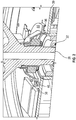
FIG. 3 is a fragmentary, perspective, sectioned illustration of part of the rotating machine ofFIG. 1 showing a ferromagnetic ring and sensor arrangement, according to an exemplary embodiment; -
FIG. 4 is an illustration of a disk with a spiral-type track for use with the rotating machine ofFIG. 1 , according to an exemplary embodiment; -
FIG. 5 is an illustration of a disk with a grooved track for use with the rotating machine ofFIG. 1 , according to an exemplary embodiment; -
FIG. 6 is an illustration of a disk with a ridged track for use with the rotating machine ofFIG. 1 , according to an exemplary embodiment; -
FIG. 7 is an illustration of a disk with an embedded ball track for use with the rotating machine ofFIG. 1 , according to an exemplary embodiment; and -
FIG. 8 is a flowchart of a method of determining angular position, according to an exemplary embodiment. - The following detailed description is merely exemplary in nature and is not intended to limit the invention or the application and uses of the invention. As used herein, the word "exemplary" means "serving as an example, instance, or illustration." Thus, any embodiment described herein as "exemplary" is not necessarily to be construed as preferred or advantageous over other embodiments. All of the embodiments described herein are exemplary embodiments provided to enable persons skilled in the art to make or use the invention and not to limit the scope of the invention which is defined by the claims. Furthermore, there is no intention to be bound by any expressed or implied theory presented in the preceding technical field, background, brief summary, or the following detailed description.
- In a number of embodiments as described herein, an output such as a sine and cosine waveform pair is desirable, such as to indicate the angular position of a rotating machine. A sine and cosine output pair provides a unique indication of any angular position of the machine. An annular track includes a feature shaped to produce the desired output and is carried with a part of the machine, such as around the shaft of the rotor. At least one sensor is carried with another part of the machine, such as its stator, and is positioned to generate a signal responsive to the moving track. The track has a feature that repeats in intervals at a periodicity. The diameter of the track is decoupled from the output because the desired periodicity may be produced at any of various sized diameters around the shaft by changing the shape of the track's feature. In a number of embodiments, the sensor(s) may be disposed on a common printed circuit board with other control components such as the drive electronics for the machine. In embodiments, this enables generating a signal for commutation where the shape of the track may be altered to match various desired numbers of pole pairs, without a need to change the diameter and packaging space needed.
- Referring to
FIG. 1 , an embodiment is illustrated aselectrical machine 20 in the form of a brushless DC motor. Themachine 20 generally includes a pair of relatively rotatable components/bodies in the form of arotor 22 and astator 24 in this embodiment. Therotor 22 and thestator 24 are carried in ahousing 26. Therotor 22 includes ashaft 28 supported in thehousing 26 bybearing assemblies ring 34 is carried by therotor 22 to move therewith and includes atrack 36. In other embodiments, thering 34 may be formed as a disk or other shape to carry thetrack 36. Thetrack 36 is generally annular in shape, surrounds theshaft 28, may be continuous or stepped, and includes a feature in the form of a shaped, repeating pattern to produce a desired output. Thestator 24 may be fixed to thehousing 26 along with a printed circuit board assembly (PCBA) 38, or in some embodiments may move relative thereto. ThePCBA 38 includes a printedcircuit board 39 andelectronic elements 40 for control purposes, which in the current embodiment includes circuit components of themotor drive electronics 41 for themachine 20. ThePCBA 38 also carries at least onesensor 46 positioned adjacent to and facing thetrack 36 to produce a signal in response to relative movement of thetrack 36. - As shown in
FIG. 2 , thetrack 36 is part of adisk 44 that is fixed to theshaft 28. A pair ofsensors circuit board 39 adjacent thetrack 36. Thesensors track 36. In the current embodiment, thesensors circuit board 39 as part of thePCBA 38. In other embodiments another type of sensor, such as an inductive may be used. - As shown in
FIG. 3 , a pair ofbias magnets openings circuit board 39. In a number of embodiments, themagnets surface 58 of the printedcircuit board 39 opposite thesurface 59 to which thesensors magnet 50 is aligned with thesensor 46 and themagnet 52 is aligned with thesensor 48. Themagnets sensors track 36 moves past theirsurfaces sensors track 36 passing near them. In the current embodiment, the features are configured to generate sinusoidal outputs as a sine and cosine pair from thesensors rotor 22. - An embodiment of the
disk 44 is illustrated inFIG. 4 and includes thetrack 36 configured with a ferrous spiral design. Thetrack 36 includes a number of identical spiral shapedridges 60 near itsouter perimeter 62 and anopening 64 at its center to receive theshaft 28. Thetrack 36 is centered on adiameter 66. As aridge 60 passes one of thesensors respective sensor ridge 60 passing by. When aridge 60 moves to a position in front of thesensor ridge 60 moves away, the output ramps down. The cycle repeats at everyridge 60 resulting in a sinusoidal output. The sinusoidal output is accomplished due to the curvature of theridges 60 and the height variation. In this embodiment, a total of sixteenridges 60 are included, which corresponds to providing an output for thirty-two poles (sixteen pole pairs) of themachine 20 for use in commutation. The amplitude of the output may be varied by varying the height of theridges 60 relative to thegrooves 65 between theridges 60. Each ridge 60 -groove 65 pair forms a segment of thetrack 36 that repeats around its circumference. Thediameter 66 of thetrack 36 may be changed to fit available packaging space and the same output may be generated such as by changing the curvature of theridges 60. Accordingly, thediameter 66 of thetrack 36 is decoupled from the output so that the same output may be obtained byvarious diameters 66. - As illustrated in
FIG. 5 , an embodiment of thedisk 44 includes thetrack 36 configured a anegative groove 68 formed into thedisk 44 near itsouter perimeter 70. Anopening 72 at the center of thedisk 44 is provided for receiving theshaft 28. Thegroove 68 may be formed concurrently with thedisk 44 of a ferro-magnetic material, such as by casting or additive manufacturing, or may be machined in. Thegroove 68 has a sinusoidal shape with a number of repeatingsegments 74 in a sequence. Thesegment 74 repeats at intervals 360-degrees around theshaft 28 with a periodicity. The number ofindividual segments 74 and their amplitude is selected based on the desired output so that the periodicity of thetrack 36 coincides with that of the desired output. The amplitude of the output may be varied by varying theheight 75 of thetrack 36, which corresponds to the variation of one-half thesegment 74. -
FIG. 6 illustrates an embodiment of thedisk 44 with thetrack 36 configured as apositive ridge 76 projecting from thesurface 78. Theridge 76 may be formed concurrently with thedisk 44 of a ferro-magnetic material, or may be added as a separate piece. When theridge 76 is added, the remainder of thedisk 44 may be formed of a nonmagnetic material. When embodied as a separate piece, theridge 76 may be adhered, bonded, fastened, fused or otherwise attached to thesurface 78. In this embodiment, theridge 76 has a sinusoidal shape composed of a repeating sequence ofsegments 80 and is configured to generate a sinusoidal response from thesensors individual segments 80 and their amplitude is selected to produce the desired output. The amplitude of the output may be varied by varying theheight 79 of theridge 76 between anoutermost point 81 and aninnermost point 83. - As illustrated in
FIG. 7 , thetrack 36 may be non-continuous or stepped around theperimeter 82 of thedisk 44. In this embodiment, thetrack 36 is a series of spaced steps in the form of ferro-magnetic elements (balls) 84 embedded in thedisk 44. Theelements 84 are positioned in a sinusoidal-like trail of thetrack 36 so that oneelement 84 results in a high output from therespective sensor next element 84 results in a low output from therespective sensor sensor track 36 rotates. Theelements 84 may be made of a ferromagnetic material and thedisk 44 may be made of a nonmagnetic material. In this embodiment, theelements 84 are secured inholes 86 bored in thedisk 44. In other embodiments, theelements 84 may be secured to the surface of thedisk 44. The number ofindividual elements 84 and theheight 88 of their positioning is selected based on the desired output. In some embodiments, such as when an on-off pulsed output is desired, theelements 84 may be spaced apart in acircular track 36 so that when an element passes asensor 46, 48 a pulse is generated and when thesensor elements 84 no pulse is generated. The amplitude of the output may be varied by varying theheight 88 of the trail between anouter element 84 and an adjacentinner element 84. - A
process 100 for determining angular position is depicted inFIG. 8 . The process begins 102 and the parameters of the output are determined 104. For example, the nature of the output such as whether it will be sinusoidal, pulsed or otherwise is determined 104. In addition, the period of the output is determined 104. As an example, for purposes of commutating a motor with thirty-two poles, sixteenridges 60,segments elements 84 are employed and are distributed 360 degrees around thedisk 44. This generates sixteen cycles per rotation. So, themachine 20, as an aspect of thetrack 36, contains a plurality of features whose periodicity exactly coincides with the periodicity of features on at least one of the relatively rotating bodies (16 segments coinciding with motor magnetic pole pairs of 16 being one example). This means the diameter of the track is decoupled from the output because the desired periodicity may be produced at any of various sized diameters around the shaft by changing the shape of the track's feature. In addition, the amplitude of the output needed is determined 104. The amplitude is varied by varying theheight track 36, or the height of theridges 60. Height is a distance between the part of thetrack 36 that generates the high point of the output and the part of the track that generates the low output. The illustrated designs ofFIGS. 4-7 desirably create a large amplitude, well-shaped sinusoidal wave, with a minimum of extraneous electrical noise. - Continuing with the
process 100, the shape of the track is selected 106. Factors determining the selected shape include preferred manufacturing process, the nature of the output, and the amplitude of the output. For example, for a sinusoidal output, any of thetracks 36 as illustrated inFIGS. 4-7 may be selected 106. The number of sensors needed is determined 108. For example, when sine and cosine inputs are needed by the applicable use of commutation, twosensors sensor - The
disk 44 is then fabricated 110 and thetrack 36 is incorporated 112 into thedisk 44. For example, thedisk 44 ofFIG. 4 may be cast of a ferromagnetic material and thegrooves 65 may be machined to form thespiral ridges 60. In the embodiment ofFIG. 5 , thedisk 44 may be cast with thegroove 68 formed as part of the casting. For the embodiment ofFIG, 6 , thedisk 44 with theridge 76 may be formed, such as by additive manufacturing, or theridge 76 may be secured to thedisk 44 after its formation. With regard to the embodiment ofFIG. 7 , thedisk 44 may be formed or machined and theholes 86 may be incorporated or bored, after which theelements 84 may be inserted. - The
machine 20 is assembled 114 with thedisk 44 secured 116 relative to theshaft 28. Thesensors circuit board 39 and themagnets circuit board 39 opposite thesensors sensors magnets PCBA 38. In the current embodiment, thePCBA 38 includes themotor drive electronics 41 for themachine 20. ThePCBA 38 is assembled 120 in themachine 20 encircling theshaft 28 so that thetrack 36 faces and is disposed adjacent thesensors track 36 and thesensors track 36 and thesensors machine 20 is operated 122 with therotor 22 rotating relative to thestator 24. As thetrack 36 passes thesensors process 100 ends 126. In a number of embodiments, an output of up to 400mV peak to peak may be generated. - Through the examples described herein, usable electrical outputs such as sine and cosine waveforms are generated in a machine using a track and at least one sensor. The sensor(s) may be mounted on the same printed
circuit board 39 as the driver electronics for the machine. Movement of the track varies a magnetic field generated by bias magnets for sensing by the sensors. The sensors are disposed in the same plane as the printed circuit board for the driver electronics and the ring rotates with the machine's shaft and the track faces the sensors. The generated output may be used to determine absolute angular position from which angular speed may be derived for a number of uses including for motor commutation. The diameter of the track may vary and the desired output is tailored by the features of the track. - While at least one exemplary embodiment has been presented in the foregoing detailed description, it should be appreciated that a vast number of variations exist. It should also be appreciated that the exemplary embodiment or exemplary embodiments are only examples, and are not intended to limit the scope, applicability, or configuration of the invention in any way. Rather, the foregoing detailed description will provide those skilled in the art with a convenient road map for implementing an exemplary embodiment of the invention. It being understood that various changes may be made in the function and arrangement of elements described in an exemplary embodiment without departing from the scope of the invention as set forth in the appended claims.
Claims (15)
- A system for determining angular position comprising:a first body including a shaft and a track having a repeating sequence of segments arranged around the shaft at a diameter of the track; anda second body, including a sensor facing the track, wherein the first and second bodies rotate relative to each other about an axis,wherein the track and the sensor face each other; andwherein the sensors are configured to generate an output that is decoupled from the diameter of the track and is related to the repeating sequence of segments.
- The system of claim 1, wherein the first body is a rotor of an electrical machine and the second body is a printed circuit card assembly fixed relative to a stator of the electrical machine, wherein the printed circuit card assembly includes the drive electronics for the electrical machine.
- The system of claim 2, wherein the printed circuit card assembly encircles the shaft.
- The system of claim 2, comprising a magnet on an opposite side of the printed circuit card assembly from the sensor.
- The system of claim 4, wherein the sensor is configured to generate a sinusoidal output as a result of the repeating sequence of segments varying a magnetic field generated by the magnets.
- The system of claim 2, wherein the sensor is disposed on the printed circuit card assembly and the track is annular in shape and is configured so that the sensor generates a sinusoidal output.
- The system of claim 1, comprising a second sensor facing the track, wherein the sensors generate the output as sine and cosine waveforms.
- The system of claim 1, wherein the track has a height and wherein the output has an amplitude related to the height.
- The system of claim 1, comprising a printed circuit card assembly carrying the sensor; and a magnet on an opposite side of the printed circuit card assembly from the sensor, wherein the sensor is configured to sense a variation in the magnetic field causes by rotation of the track.
- The system of claim 1, wherein the first body is a rotor of an electrical machine having a number of pole pairs, and wherein the repeating sequence of segments comprise the number, so that the sensor generates the output to commutate the electrical machine.
- A method for determining angular position comprising:arranging a repeating sequence of segments in a track disposed at a diameter around a shaft of a first body;positioning a sensor on a second body, the sensor facing the track;configuring the first and second bodies to rotate relative to each other about an axis;mounting the track and the sensor to face each other; andgenerating, by the sensor, an output that is decoupled from the diameter of the track and is related to the repeating sequence of segments.
- The method of claim 11, comprising:configuring the first body as a rotor of an electrical machine;configuring the second body as a printed circuit card assembly that is fixed relative to a stator of the electrical machine; andincluding, in the printed circuit card assembly, drive electronics for the electrical machine.
- The method of claim 12, comprising encircling the shaft with the printed circuit card assembly.
- The method of claim 12, comprising positioning a magnet on an opposite side of the printed circuit card assembly from the sensor.
- The method of claim 14, comprising:varying a magnetic field generated by the magnets by movement of the repeating sequence of segments; andgenerating, by the sensor, a sinusoidal output as a result of the repeating sequence of segments passing across the sensor.
Applications Claiming Priority (1)
| Application Number | Priority Date | Filing Date | Title |
|---|---|---|---|
| US16/899,258 US11519757B2 (en) | 2020-06-11 | 2020-06-11 | System and method for determining angular position in rotating machines |
Publications (2)
| Publication Number | Publication Date |
|---|---|
| EP3922954A1 true EP3922954A1 (en) | 2021-12-15 |
| EP3922954B1 EP3922954B1 (en) | 2026-02-11 |
Family
ID=76076270
Family Applications (1)
| Application Number | Title | Priority Date | Filing Date |
|---|---|---|---|
| EP21175542.6A Active EP3922954B1 (en) | 2020-06-11 | 2021-05-24 | System for determining angular position in rotating machines and use of such system |
Country Status (2)
| Country | Link |
|---|---|
| US (1) | US11519757B2 (en) |
| EP (1) | EP3922954B1 (en) |
Citations (6)
| Publication number | Priority date | Publication date | Assignee | Title |
|---|---|---|---|---|
| US6522130B1 (en) * | 1998-07-20 | 2003-02-18 | Uqm Technologies, Inc. | Accurate rotor position sensor and method using magnet and sensors mounted adjacent to the magnet and motor |
| US20100308808A1 (en) * | 2007-11-20 | 2010-12-09 | Sumida Corporation | Rotation angle detecting sensor |
| US20170292855A1 (en) * | 2016-04-07 | 2017-10-12 | John Kaste | Multipole Magnet for Use With A Pitched Magnetic Sensor |
| US20180356254A1 (en) * | 2015-05-13 | 2018-12-13 | Schaeffler Technologies AG & Co. KG | Sensor arrangement comprising an angle sensor and rolling bearing arrangement comprising sensor arrangement |
| US20190265073A1 (en) * | 2016-09-13 | 2019-08-29 | Ntn-Snr Roulements | System for determining at least one rotation parameter of a rotating member |
| US20200166376A1 (en) * | 2017-07-13 | 2020-05-28 | Azoteq (Pty) Ltd | Inductive sensing user interface devices |
Family Cites Families (37)
| Publication number | Priority date | Publication date | Assignee | Title |
|---|---|---|---|---|
| JPS5613244B2 (en) * | 1974-07-31 | 1981-03-27 | ||
| FR2384174A1 (en) | 1977-03-15 | 1978-10-13 | Aerospatiale | INERTIA WHEEL |
| US4475068A (en) | 1980-03-03 | 1984-10-02 | Brailsford Harrison D | Brushless direct current motor with magnetically operated commutating switch means |
| JPS62105012A (en) * | 1985-10-31 | 1987-05-15 | Ebara Res Co Ltd | Bearing device with rotation detector |
| US4732353A (en) | 1985-11-07 | 1988-03-22 | The United States Of America As Represented By The Administrator Of The National Aeronautics And Space Administration | Three axis attitude control system |
| US5625239A (en) | 1992-06-03 | 1997-04-29 | Trw Inc. | Method and apparatus for sensing relative position between two relatively rotatable members using concentric rings |
| JPH07337076A (en) | 1994-06-07 | 1995-12-22 | Matsushita Electric Ind Co Ltd | 3-phase brushless servomotor |
| US5623409A (en) | 1994-10-31 | 1997-04-22 | Trw Inc. | Method and apparatus for non-linear damping of an electric assist steering system for vehicle yaw rate control |
| US5675250A (en) * | 1995-04-28 | 1997-10-07 | Caterpillar Inc. | Angular position sensor having no physical electrical contact between a rotating portion and a stationary portion of the sensor |
| US5731645A (en) | 1996-02-05 | 1998-03-24 | Magnetic Bearing Technologies, Inc. | Integrated motor/generator/flywheel utilizing a solid steel rotor |
| JP3726418B2 (en) * | 1997-04-18 | 2005-12-14 | 株式会社デンソー | Rotation detector |
| JP2000134977A (en) | 1998-10-29 | 2000-05-12 | Alps Electric Co Ltd | Driving device for polyphase motor |
| US6313624B1 (en) * | 1998-11-27 | 2001-11-06 | The United States Of America As Represented By The Administrator Of The National Aeronautics And Space Administration | Position sensor with integrated signal-conditioning electronics on a printed wiring board |
| US6211794B1 (en) * | 2000-04-06 | 2001-04-03 | Borgwarner | Analog rotary position sensor |
| DE10219807C1 (en) * | 2002-05-02 | 2003-07-17 | Bruss Dichtungstechnik | Angular rotation of machine part measuring device, has magnets of sinusoidally-varying thickness around circumference |
| FR2845212B1 (en) | 2002-09-27 | 2005-03-18 | Roulements Soc Nouvelle | DEVICE FOR CONTROLLING AN ELECTRONICALLY SWITCHED MOTOR USING A POSITION SIGNAL |
| US6911817B2 (en) * | 2002-12-23 | 2005-06-28 | American Electronics Components, Inc. | Wheel-speed sensor |
| US6679457B1 (en) | 2003-01-13 | 2004-01-20 | Honeywell International Inc. | Reaction wheel system with vernier control rotor |
| DE10309027A1 (en) * | 2003-03-01 | 2004-09-16 | Micro-Hybrid Electronic Gmbh | Absolute angle measuring device, has two rings with Archemedes spirals scanned by sensors on radius, with additional sensors lying outside radius |
| DE10354604B4 (en) | 2003-11-21 | 2016-10-13 | Gesellschaft für Aufladetechnik und Spindelbau mbH | Infinitely variable, magnetodynamic transmission |
| JP4158858B2 (en) | 2003-12-04 | 2008-10-01 | 多摩川精機株式会社 | Rotation angle detector |
| WO2007012419A2 (en) | 2005-07-26 | 2007-02-01 | Ebm-Papst St. Georgen Gmbh & Co. Kg | Absolute encoder and method for generating an absolute value for an angle of rotation |
| JP2007285774A (en) * | 2006-04-13 | 2007-11-01 | Toyota Motor Corp | Magnetic resolver and manufacturing method thereof |
| US20080099626A1 (en) | 2006-10-27 | 2008-05-01 | Goodrich Corporation | Reconfigurable reaction wheel for spacecraft |
| DE102008008377B3 (en) * | 2008-02-09 | 2009-09-24 | Harmonic Drive Ag | Material measure for use in i.e. angle measuring system, has carrier body provided for structure, where structure and carrier body are formed by common component such as injection molding part or plastic part |
| US8193748B2 (en) | 2008-10-10 | 2012-06-05 | Smi Holdings, Inc. | Integrated brushless DC motor and controller |
| JP5716954B2 (en) * | 2011-01-17 | 2015-05-13 | 株式会社ジェイテクト | Rotation angle detector |
| DE102011005066B4 (en) | 2011-03-03 | 2024-08-08 | Robert Bosch Gmbh | Sensor arrangement |
| JP5764373B2 (en) | 2011-04-15 | 2015-08-19 | 株式会社一宮電機 | Variable reluctance resolver |
| US8918236B2 (en) | 2011-06-24 | 2014-12-23 | Honeywell International Inc. | Methods and systems for adjusting attitude using reaction wheels |
| GB2506698A (en) * | 2012-10-02 | 2014-04-09 | Mark Anthony Howard | Detector to measure the relative position of bodies |
| CZ2013163A3 (en) | 2013-03-05 | 2014-04-30 | Lesikar, A.S. | Speed sensor |
| WO2017046953A1 (en) | 2015-09-18 | 2017-03-23 | 三菱電機株式会社 | Permanent magnet synchronous motor, permanent magnet synchronous motor manufacturing method, and air conditioner |
| EP3163256B1 (en) * | 2015-10-26 | 2019-12-04 | TE Connectivity Germany GmbH | Magnetic angle sensor comprising two concentric rings of coprime magnetic spiral portions |
| JP6546565B2 (en) | 2016-06-02 | 2019-07-17 | 日本電産サンキョー株式会社 | Linear motion rotation detector, linear motion rotation detector unit and linear motion rotation drive device |
| DE102017204415A1 (en) | 2017-03-16 | 2018-09-20 | Robert Bosch Gmbh | EC motor with an annular sensor magnet |
| EP4194816A1 (en) | 2018-03-14 | 2023-06-14 | Honeywell International Inc. | Off-axis magnetic angular sensor using a magnetic sensing probe and multi-pole magnet array |
-
2020
- 2020-06-11 US US16/899,258 patent/US11519757B2/en active Active
-
2021
- 2021-05-24 EP EP21175542.6A patent/EP3922954B1/en active Active
Patent Citations (6)
| Publication number | Priority date | Publication date | Assignee | Title |
|---|---|---|---|---|
| US6522130B1 (en) * | 1998-07-20 | 2003-02-18 | Uqm Technologies, Inc. | Accurate rotor position sensor and method using magnet and sensors mounted adjacent to the magnet and motor |
| US20100308808A1 (en) * | 2007-11-20 | 2010-12-09 | Sumida Corporation | Rotation angle detecting sensor |
| US20180356254A1 (en) * | 2015-05-13 | 2018-12-13 | Schaeffler Technologies AG & Co. KG | Sensor arrangement comprising an angle sensor and rolling bearing arrangement comprising sensor arrangement |
| US20170292855A1 (en) * | 2016-04-07 | 2017-10-12 | John Kaste | Multipole Magnet for Use With A Pitched Magnetic Sensor |
| US20190265073A1 (en) * | 2016-09-13 | 2019-08-29 | Ntn-Snr Roulements | System for determining at least one rotation parameter of a rotating member |
| US20200166376A1 (en) * | 2017-07-13 | 2020-05-28 | Azoteq (Pty) Ltd | Inductive sensing user interface devices |
Also Published As
| Publication number | Publication date |
|---|---|
| US20210389162A1 (en) | 2021-12-16 |
| EP3922954B1 (en) | 2026-02-11 |
| US11519757B2 (en) | 2022-12-06 |
Similar Documents
| Publication | Publication Date | Title |
|---|---|---|
| EP1099092B1 (en) | Brushless electric motor with two perpendicular Hall transducers | |
| KR101127196B1 (en) | Axil air-gap electronic motor | |
| KR102477526B1 (en) | Magnet ring with jitter pole | |
| KR102769489B1 (en) | Magnetic sensor system for motor control | |
| US10594235B2 (en) | Axial flux motor with built-in optical encoder | |
| US10340773B2 (en) | Brushless motor having an outer rotor and an annular separation plate between the drive magnet and the position detection magnet | |
| CN102654385B (en) | Sensor arrangement | |
| JPH11248486A (en) | Pickup of rotating shaft position and speed | |
| JPH08136558A (en) | Rotation speed detector | |
| JP4352189B2 (en) | Magnetic encoder and motor with magnetic encoder | |
| KR20240018467A (en) | motion detector | |
| EP3922954B1 (en) | System for determining angular position in rotating machines and use of such system | |
| US20020175678A1 (en) | Arrangement for determining the position of a motion sensor element | |
| JP2018048870A (en) | Rotation angle detector | |
| US6603304B2 (en) | Index position detector for spindle motor and motor apparatus including the same | |
| JPS6028760A (en) | Reversible brushless motor without position detector with magnetic encoder | |
| JP2006010366A (en) | Rotation detecting apparatus | |
| JP2012021840A (en) | Sensor target and rotation angle detecting apparatus | |
| JP2005127378A (en) | Bearing with absolute encoder | |
| JPS60170456A (en) | Brushless motor having frequency generator | |
| JPH0737323A (en) | Index signal generator | |
| KR20000008532U (en) | Wheel speed sensor | |
| MXPA01000770A (en) | Accurate rotor position sensor, method using magnet ring and linear output hall effect sensors | |
| HK40019926A (en) | Axial flux motor with built-in optical encoder | |
| JPH02206351A (en) | Brushless motor provided with frequency generator |
Legal Events
| Date | Code | Title | Description |
|---|---|---|---|
| PUAI | Public reference made under article 153(3) epc to a published international application that has entered the european phase |
Free format text: ORIGINAL CODE: 0009012 |
|
| STAA | Information on the status of an ep patent application or granted ep patent |
Free format text: STATUS: THE APPLICATION HAS BEEN PUBLISHED |
|
| AK | Designated contracting states |
Kind code of ref document: A1 Designated state(s): AL AT BE BG CH CY CZ DE DK EE ES FI FR GB GR HR HU IE IS IT LI LT LU LV MC MK MT NL NO PL PT RO RS SE SI SK SM TR |
|
| B565 | Issuance of search results under rule 164(2) epc |
Effective date: 20211012 |
|
| RAP3 | Party data changed (applicant data changed or rights of an application transferred) |
Owner name: HONEYWELL INTERNATIONAL INC. |
|
| STAA | Information on the status of an ep patent application or granted ep patent |
Free format text: STATUS: REQUEST FOR EXAMINATION WAS MADE |
|
| 17P | Request for examination filed |
Effective date: 20220610 |
|
| RBV | Designated contracting states (corrected) |
Designated state(s): AL AT BE BG CH CY CZ DE DK EE ES FI FR GB GR HR HU IE IS IT LI LT LU LV MC MK MT NL NO PL PT RO RS SE SI SK SM TR |
|
| STAA | Information on the status of an ep patent application or granted ep patent |
Free format text: STATUS: EXAMINATION IS IN PROGRESS |
|
| 17Q | First examination report despatched |
Effective date: 20230208 |
|
| P01 | Opt-out of the competence of the unified patent court (upc) registered |
Effective date: 20230421 |
|
| GRAP | Despatch of communication of intention to grant a patent |
Free format text: ORIGINAL CODE: EPIDOSNIGR1 |
|
| STAA | Information on the status of an ep patent application or granted ep patent |
Free format text: STATUS: GRANT OF PATENT IS INTENDED |
|
| INTG | Intention to grant announced |
Effective date: 20250911 |
|
| GRAS | Grant fee paid |
Free format text: ORIGINAL CODE: EPIDOSNIGR3 |
|
| GRAA | (expected) grant |
Free format text: ORIGINAL CODE: 0009210 |
|
| STAA | Information on the status of an ep patent application or granted ep patent |
Free format text: STATUS: THE PATENT HAS BEEN GRANTED |
|
| AK | Designated contracting states |
Kind code of ref document: B1 Designated state(s): AL AT BE BG CH CY CZ DE DK EE ES FI FR GB GR HR HU IE IS IT LI LT LU LV MC MK MT NL NO PL PT RO RS SE SI SK SM TR |
|
| REG | Reference to a national code |
Ref country code: CH Ref legal event code: F10 Free format text: ST27 STATUS EVENT CODE: U-0-0-F10-F00 (AS PROVIDED BY THE NATIONAL OFFICE) Effective date: 20260211 Ref country code: GB Ref legal event code: FG4D |
|
| REG | Reference to a national code |
Ref country code: DE Ref legal event code: R096 Ref document number: 602021047597 Country of ref document: DE |
|
| REG | Reference to a national code |
Ref country code: IE Ref legal event code: FG4D |
|
| REG | Reference to a national code |
Ref country code: NL Ref legal event code: MP Effective date: 20260211 |
|
| PG25 | Lapsed in a contracting state [announced via postgrant information from national office to epo] |
Ref country code: RS Free format text: LAPSE BECAUSE OF FAILURE TO SUBMIT A TRANSLATION OF THE DESCRIPTION OR TO PAY THE FEE WITHIN THE PRESCRIBED TIME-LIMIT Effective date: 20260511 |
|
| PG25 | Lapsed in a contracting state [announced via postgrant information from national office to epo] |
Ref country code: ES Free format text: LAPSE BECAUSE OF FAILURE TO SUBMIT A TRANSLATION OF THE DESCRIPTION OR TO PAY THE FEE WITHIN THE PRESCRIBED TIME-LIMIT Effective date: 20260211 |
|
| PG25 | Lapsed in a contracting state [announced via postgrant information from national office to epo] |
Ref country code: PL Free format text: LAPSE BECAUSE OF FAILURE TO SUBMIT A TRANSLATION OF THE DESCRIPTION OR TO PAY THE FEE WITHIN THE PRESCRIBED TIME-LIMIT Effective date: 20260211 |
|
| PGFP | Annual fee paid to national office [announced via postgrant information from national office to epo] |
Ref country code: GB Payment date: 20260525 Year of fee payment: 6 |
|
| PG25 | Lapsed in a contracting state [announced via postgrant information from national office to epo] |
Ref country code: GR Free format text: LAPSE BECAUSE OF FAILURE TO SUBMIT A TRANSLATION OF THE DESCRIPTION OR TO PAY THE FEE WITHIN THE PRESCRIBED TIME-LIMIT Effective date: 20260512 |
|
| REG | Reference to a national code |
Ref country code: LT Ref legal event code: MG9D |
|
| PG25 | Lapsed in a contracting state [announced via postgrant information from national office to epo] |
Ref country code: LT Free format text: LAPSE BECAUSE OF FAILURE TO SUBMIT A TRANSLATION OF THE DESCRIPTION OR TO PAY THE FEE WITHIN THE PRESCRIBED TIME-LIMIT Effective date: 20260211 |
|
| PGFP | Annual fee paid to national office [announced via postgrant information from national office to epo] |
Ref country code: DE Payment date: 20260522 Year of fee payment: 6 |
|
| PG25 | Lapsed in a contracting state [announced via postgrant information from national office to epo] |
Ref country code: NO Free format text: LAPSE BECAUSE OF FAILURE TO SUBMIT A TRANSLATION OF THE DESCRIPTION OR TO PAY THE FEE WITHIN THE PRESCRIBED TIME-LIMIT Effective date: 20260511 |
|
| PG25 | Lapsed in a contracting state [announced via postgrant information from national office to epo] |
Ref country code: FI Free format text: LAPSE BECAUSE OF FAILURE TO SUBMIT A TRANSLATION OF THE DESCRIPTION OR TO PAY THE FEE WITHIN THE PRESCRIBED TIME-LIMIT Effective date: 20260211 Ref country code: SE Free format text: LAPSE BECAUSE OF FAILURE TO SUBMIT A TRANSLATION OF THE DESCRIPTION OR TO PAY THE FEE WITHIN THE PRESCRIBED TIME-LIMIT Effective date: 20260211 Ref country code: AT Free format text: LAPSE BECAUSE OF FAILURE TO SUBMIT A TRANSLATION OF THE DESCRIPTION OR TO PAY THE FEE WITHIN THE PRESCRIBED TIME-LIMIT Effective date: 20260211 |
|
| REG | Reference to a national code |
Ref country code: AT Ref legal event code: MK05 Ref document number: 1885986 Country of ref document: AT Kind code of ref document: T Effective date: 20260211 |
|
| PG25 | Lapsed in a contracting state [announced via postgrant information from national office to epo] |
Ref country code: HR Free format text: LAPSE BECAUSE OF FAILURE TO SUBMIT A TRANSLATION OF THE DESCRIPTION OR TO PAY THE FEE WITHIN THE PRESCRIBED TIME-LIMIT Effective date: 20260211 |
|
| PG25 | Lapsed in a contracting state [announced via postgrant information from national office to epo] |
Ref country code: IS Free format text: LAPSE BECAUSE OF FAILURE TO SUBMIT A TRANSLATION OF THE DESCRIPTION OR TO PAY THE FEE WITHIN THE PRESCRIBED TIME-LIMIT Effective date: 20260611 Ref country code: PT Free format text: LAPSE BECAUSE OF FAILURE TO SUBMIT A TRANSLATION OF THE DESCRIPTION OR TO PAY THE FEE WITHIN THE PRESCRIBED TIME-LIMIT Effective date: 20260611 |
|
| PG25 | Lapsed in a contracting state [announced via postgrant information from national office to epo] |
Ref country code: NL Free format text: LAPSE BECAUSE OF FAILURE TO SUBMIT A TRANSLATION OF THE DESCRIPTION OR TO PAY THE FEE WITHIN THE PRESCRIBED TIME-LIMIT Effective date: 20260211 |
|
| PGFP | Annual fee paid to national office [announced via postgrant information from national office to epo] |
Ref country code: FR Payment date: 20260521 Year of fee payment: 6 |
|
| PG25 | Lapsed in a contracting state [announced via postgrant information from national office to epo] |
Ref country code: LV Free format text: LAPSE BECAUSE OF FAILURE TO SUBMIT A TRANSLATION OF THE DESCRIPTION OR TO PAY THE FEE WITHIN THE PRESCRIBED TIME-LIMIT Effective date: 20260211 |
|
| PG25 | Lapsed in a contracting state [announced via postgrant information from national office to epo] |
Ref country code: BG Free format text: LAPSE BECAUSE OF FAILURE TO SUBMIT A TRANSLATION OF THE DESCRIPTION OR TO PAY THE FEE WITHIN THE PRESCRIBED TIME-LIMIT Effective date: 20260211 |