EP3922889A1 - Flow path switch valve - Google Patents
Flow path switch valve Download PDFInfo
- Publication number
- EP3922889A1 EP3922889A1 EP19914596.2A EP19914596A EP3922889A1 EP 3922889 A1 EP3922889 A1 EP 3922889A1 EP 19914596 A EP19914596 A EP 19914596A EP 3922889 A1 EP3922889 A1 EP 3922889A1
- Authority
- EP
- European Patent Office
- Prior art keywords
- valve
- flow channel
- valve member
- opening
- valve shaft
- Prior art date
- Legal status (The legal status is an assumption and is not a legal conclusion. Google has not performed a legal analysis and makes no representation as to the accuracy of the status listed.)
- Granted
Links
Images



Classifications
-
- F—MECHANICAL ENGINEERING; LIGHTING; HEATING; WEAPONS; BLASTING
- F16—ENGINEERING ELEMENTS AND UNITS; GENERAL MEASURES FOR PRODUCING AND MAINTAINING EFFECTIVE FUNCTIONING OF MACHINES OR INSTALLATIONS; THERMAL INSULATION IN GENERAL
- F16K—VALVES; TAPS; COCKS; ACTUATING-FLOATS; DEVICES FOR VENTING OR AERATING
- F16K11/00—Multiple-way valves, e.g. mixing valves; Pipe fittings incorporating such valves
- F16K11/02—Multiple-way valves, e.g. mixing valves; Pipe fittings incorporating such valves with all movable sealing faces moving as one unit
- F16K11/08—Multiple-way valves, e.g. mixing valves; Pipe fittings incorporating such valves with all movable sealing faces moving as one unit comprising only taps or cocks
- F16K11/087—Multiple-way valves, e.g. mixing valves; Pipe fittings incorporating such valves with all movable sealing faces moving as one unit comprising only taps or cocks with spherical plug
- F16K11/0873—Multiple-way valves, e.g. mixing valves; Pipe fittings incorporating such valves with all movable sealing faces moving as one unit comprising only taps or cocks with spherical plug the plug being only rotatable around one spindle
-
- F—MECHANICAL ENGINEERING; LIGHTING; HEATING; WEAPONS; BLASTING
- F16—ENGINEERING ELEMENTS AND UNITS; GENERAL MEASURES FOR PRODUCING AND MAINTAINING EFFECTIVE FUNCTIONING OF MACHINES OR INSTALLATIONS; THERMAL INSULATION IN GENERAL
- F16K—VALVES; TAPS; COCKS; ACTUATING-FLOATS; DEVICES FOR VENTING OR AERATING
- F16K5/00—Plug valves; Taps or cocks comprising only cut-off apparatus having at least one of the sealing faces shaped as a more or less complete surface of a solid of revolution, the opening and closing movement being predominantly rotary
- F16K5/06—Plug valves; Taps or cocks comprising only cut-off apparatus having at least one of the sealing faces shaped as a more or less complete surface of a solid of revolution, the opening and closing movement being predominantly rotary with plugs having spherical surfaces; Packings therefor
- F16K5/0647—Spindles or actuating means
Definitions
- the round columnar portion 51 has a stopper portion 53 on its lower end portion.
- the stopper portion 53 has an annular shape and extends outward in the radial direction.
- the outer diameter of the stopper portion 53 is larger than the inner diameter of the bearing portion 45.
- the valve member 20 has a relatively simple structure and can be easily manufactured.
Landscapes
- Engineering & Computer Science (AREA)
- General Engineering & Computer Science (AREA)
- Mechanical Engineering (AREA)
- Taps Or Cocks (AREA)
- Multiple-Way Valves (AREA)
Abstract
Description
- The present invention relates to a flow channel switching valve that switches between connections of flow channels by rotating a valve member.
- An example of an existing flow channel switching valve is disclosed in
Patent Literature 1. The flow channel switching valve includes a valve body that has a valve chamber, a valve member that is disposed in the valve chamber, a valve shaft that is connected to the valve member, and a rotational driving section that includes, for example, a drive gear and a motor that rotationally drives the valve member via the valve shaft. - The valve member of the flow channel switching valve has a hexagonal vertical through hole. The valve shaft having a hexagonal cross-section is inserted into an upper portion of the vertical through hole. As a result, the valve member is connected to the valve shaft. Rotation of the valve shaft makes the valve member rotating. In addition, the valve member has a circular transverse hole that is selectively communicated with two outflow ports formed in the valve body.
- Patent Literature 1:
Japanese Unexamined Patent Application Publication No. 2018-115690 - However, in the valve member of the flow channel switching valve described above, since a corner portion of the hexagonal vertical through hole is disposed in a beam part between the vertical through hole and the transverse hole, the beam part has a thinner shape. Thus, in manufacturing the valve member by injection molding, resin flows may meet in the beam part. This may generate a weld line and decrease the rigidity of the beam part.
- In view of this, it is an object of the present invention to provide a flow channel switching valve that can effectively suppress decreasing the rigidity of a beam part of a valve member.
- To achieve the object described above, a flow channel switching valve of the present invention includes a valve body that has a valve chamber and flow channels in communication with the valve chamber, a valve member that is rotatably installed in the valve chamber and that switches between connections of the flow channels depending on a rotational position of the valve member, a valve shaft that is mounted in the valve member along a rotational axis of the valve member, and a driving section that rotates the valve member via the valve shaft. The valve member has a transverse hole in communication with a switching flow channel formed in the valve member, and a vertical hole in which the valve shaft is inserted. When viewed in the direction of the rotational axis, the vertical hole has an outward convex corner portion, and the corner portion is shifted from a beam part between the transverse hole and the vertical hole.
- In the present invention, the vertical hole is preferably in communication with the switching flow channel.
- In the present invention, the vertical hole preferably has a polygonal shape.
- In the present invention, when viewed in the direction of the rotational axis, the transverse hole is preferably formed such that a center line of the transverse hole is perpendicular to a side portion of the polygonal shape.
- In the present invention, the vertical hole preferably has a polygonal shape with corner portions in multiples of three or four.
- In the present invention, the vertical hole preferably has a quadrangular shape.
- In the present invention, the vertical hole preferably has a triangular shape.
- In the present invention, the valve member is preferably resin-molded in a spherical shape and has a gate mark only on an outer surface of a wall portion that faces the vertical hole.
- According to the present invention, the valve member in which the valve shaft is mounted has the transverse hole in communication with the switching flow channel formed in the valve member, and the vertical hole in which the valve shaft is inserted. When viewed in the direction of the rotational axis of the valve member, the vertical hole has the outward convex corner portion, and the corner portion is shifted from the beam part between the transverse hole and the vertical hole. In this way, it is possible to avoid the beam part of the valve member having a thinner shape and effectively suppress decreasing the rigidity of the beam part of the valve member. Due to the vertical hole in which the valve shaft is inserted has a polygonal shape such as a triangular shape, a quadrangular shape, a hexagonal shape, or an octagonal shape, the valve member has a relatively simple structure and can be easily manufactured.
-
- [
Fig. 1] Fig. 1 is a perspective view containing a cross-section of a flow channel switching valve according to an embodiment of the present invention. - [
Fig. 2] Fig. 2 is a cross-sectional view taken along line A-A inFig. 1 . - [
Fig. 3] Fig. 3 is a perspective view of a ball valve member and a valve shaft that the flow channel switching valve inFig. 1 includes. - [
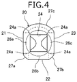
Fig. 4] Fig. 4 is a plan view of the ball valve member. - [
Fig. 5] Figs. 5 are plan views illustrating modifications of the ball valve member. - A flow channel switching valve according to an embodiment of the present invention will now be described with reference to
Fig. 1 to Figs. 5 . -
Fig. 1 is a perspective view containing a cross-section of the flow channel switching valve according to the embodiment of the present invention.Fig. 2 is a cross-sectional view taken along line A-A inFig. 1 .Fig. 3 is a perspective view of a ball valve member and a valve shaft of the flow channel switching valve inFig. 1 .Fig. 4 is a plan view of the ball valve member that the flow channel switching valve according to the present embodiment includes.Figs. 5(a) to 5(e) are plan views illustrating modifications of the ball valve member. In the following description, the terms "upper, lower, left, and right" are used to represent relative positional relationships of components in the figures and do not represent absolute positional relationships. In the figures, an X-axis direction represents a left-and-right direction, a Y-axis direction represents a front-and-rear direction (a front-back direction), and a Z-axis direction represents an up- and-down direction. An X-axis, a Y-axis, a Z-axis are perpendicular to each other. A direction along a rotational axis of the valve member (a direction of a rotational axis) represents a vertical direction, and a direction perpendicular to the rotational axis represents a transverse direction. - As illustrated in
Fig. 1 andFig. 2 , a flowchannel switching valve 1 according to the present embodiment includes avalve body 10, aball valve member 20,seat members 30, sealingmembers 31, adriving section 40, and avalve shaft 50. The flowchannel switching valve 1 further includes apotentiometer shaft 60 corresponding to a rotational angle output shaft, apotentiometer base 70 corresponding to a base body, and apotentiometer 80 corresponding to a rotational angle detection portion. - The
valve body 10 is composed of synthetic resin and has a substantially cubic box shape. Afirst flow channel 11 that has a substantially L-shape is formed on a leftside wall portion 10a of thevalve body 10. Asecond flow channel 12 that is linear is formed on afront wall portion 10b of thevalve body 10. Athird flow channel 13 that is plane-symmetrical with thefirst flow channel 11 and that has a substantially L-shape is formed on a rightside wall portion 10c of thevalve body 10. An opening 11a of thefirst flow channel 11, an opening 12a of thesecond flow channel 12, and an opening 13a of thethird flow channel 13 are directed in the same direction (the front direction). Thefirst flow channel 11, thesecond flow channel 12, and thethird flow channel 13 are in communication with avalve chamber 14 that is formed in thevalve body 10. Two flow channels or four or more flow channels in communication with thevalve chamber 14 may be formed. - The
ball valve member 20 is composed of, for example, a material such as synthetic resin and has a hollow ball-like shape (a spherical shape). Theball valve member 20 is rotatably supported by theseat members 30 described later and is installed in thevalve chamber 14. Theball valve member 20 has afirst opening 21 that is a transverse hole opened toward the left-hand direction, a second opening 22 that is a transverse hole opened toward the front direction, and a third opening 23 that is a transverse hole opened toward the right-hand direction when theball valve member 20 is located at a rotational position illustrated inFig. 2 . Aswitching flow channel 25 is formed in theball valve member 20. Theswitching flow channel 25 has a substantially T-shape in a plan view and that connects thefirst opening 21, the second opening 22, and the third opening 23 to each other. In other words, the first opening 21, the second opening 22, and the third opening 23 are connected to theswitching flow channel 25. For example, theball valve member 20 may have only thefirst opening 21 and thesecond opening 22. Theball valve member 20 may have theswitching flow channel 25 that has a substantially L-shape in a plan view and that connects thefirst opening 21 and thesecond opening 22 to each other when theball valve member 20 is located at the rotational position illustrated inFig. 2 . In the present embodiment, theball valve member 20 is used as the valve member, but a columnar valve member may be used. - The switching
flow channel 25 switches between the connections among thefirst flow channel 11, thesecond flow channel 12, and thethird flow channel 13 depending on the rotational position of theball valve member 20. Specifically, the switchingflow channel 25 connects thefirst flow channel 11, thesecond flow channel 12, and thethird flow channel 13 to each other when theball valve member 20 is located at the rotational position illustrated inFig. 2 . The switchingflow channel 25 connects thefirst flow channel 11 and thesecond flow channel 12 to each other when theball valve member 20 is located at the rotational position at which theball valve member 20 is rotated 90 degrees clockwise in a plan view from the rotational position illustrated inFig. 2 . The switchingflow channel 25 connects thesecond flow channel 12 and thethird flow channel 13 to each other when theball valve member 20 is located at the rotational position at which theball valve member 20 is rotated 90 degrees counterclockwise in a plan view from the rotational position illustrated inFig. 2 . - A valve
shaft insertion hole 24 is formed in an upper portion of theball valve member 20. A valveshaft insertion hole 24 is a vertical hole in which thevalve shaft 50 described later is inserted. The valveshaft insertion hole 24 is in communication with theswitching flow channel 25. The valveshaft insertion hole 24 is inserted thevalve shaft 50 therein. The valveshaft insertion hole 24 is formed such that rotation of thevalve shaft 50 makes theball valve 20 rotating about an axis L corresponding to a rotational axis. Specifically, the valveshaft insertion hole 24 has the same shape as a cross-sectional shape (a transverse cross-sectional shape) in the direction perpendicular to the axial direction of theprism portion 52 of thevalve shaft 50. In the present embodiment, when viewed in the direction along the axis L (the direction of the rotational axis), the valveshaft insertion hole 24 has a square shape as illustrated inFig. 4 . - The valve
shaft insertion hole 24 has a square shape and has four outwardconvex corner portions 24a. Each of the fourcorner portions 24a is shifted from abeam part 26a between thefirst opening 21 and the valveshaft insertion hole 24, abeam part 26b between thesecond opening 22 and the valveshaft insertion hole 24, and abeam part 26c between thethird opening 23 and the valveshaft insertion hole 24. In other words, each of the fourcorner portions 24a of the valveshaft insertion hole 24 is disposed facing aperipheral wall part 27a between thefirst opening 21 and thesecond opening 22, aperipheral wall part 27b between thesecond opening 22 and thethird opening 23, or aperipheral wall part 27c between thethird opening 23 and thefirst opening 21. The valveshaft insertion hole 24 faces abottom wall part 28 corresponding to a lower wall part of theball valve member 20, in the direction along the axis L. -
Figs. 5(a) to 5(c) illustrate the modifications that can be employed in place of the valveshaft insertion hole 24.Fig. 5(a) illustrates a valveshaft insertion hole 24A formed by curving each side of a square shape inward.Fig. 5(b) illustrates a valveshaft insertion hole 24B having a cross shape.Fig. 5(c) illustrates a valve shaft insertion hole 24C having an octagonal shape. In the valve shaft insertion holes 24A, 24B, and 24C, each of thecorner portions 24a is also shifted from thebeam parts shaft insertion hole 24 in the present embodiment. That is, each of thecorner portions 24a is disposed facing theperipheral wall parts - In addition,
Figs. 5(d) and 5(e) illustrateball valve members first opening 21 and thesecond opening 22. Thefirst opening 21 and thesecond opening 22 are two transverse holes and are formed about the axis L.Fig. 5(d) illustrates the modification with a valveshaft insertion hole 24D having a triangular shape.Fig. 5(e) illustrates the modification with a valveshaft insertion hole 24E having a hexagonal shape. In the valveshaft insertion holes corner portions 24a is also shifted from thebeam parts shaft insertion hole 24 in the present embodiment. That is, each of thecorner portions 24a is disposed facing theperipheral wall parts ball valve members valve body 10 is disposed to correspond to thefirst opening 21 and thesecond opening 22 illustrated inFigs 5(d) and 5(e) . The dashed lines inFigs. 4 and5(a) to 5(e) show the cross-sectional shapes of the flow channels including the transverse holes in each of the valve members. - In any of ball valve members illustrated in
Figs 5 , each of thecorner portions 24a of the valve shaft insertion hole is also shifted from thebeam parts corner portions 24a is disposed facing theperipheral wall parts first opening 21, thesecond opening 22, and thethird opening 23 is perpendicular to the side portion of the quadrangular shape in the valveshaft insertion hole 24. Thefirst opening 21, thesecond opening 22, and thethird opening 23 are the transverse holes. - The
seat members 30 are composed of, for example, synthetic resin such as polytetrafluoroethylene (PTFE) and have an annular shape. Theseat members 30 are paired with each other and are installed in thevalve chamber 14 so as to face each other in an interval in the X-axis direction. Theseat members 30 that theball valve member 20 is disposed therebetween rotatably support theball valve member 20 in thevalve chamber 14. - The sealing
members 31 are, for example, O-rings composed of an elastic material such as a rubber material, one of which is disposed between one of theseat members 30 and the leftside wall portion 10a of thevalve body 10 in a compressed state, and the other of which is disposed between theother seat member 30 and the rightside wall portion 10c of thevalve body 10 in the compressed state. In the present embodiment, the sealingmembers 31 are fitted inannular grooves 30a that theseat members 30 have and partly project from theannular grooves 30a. The sealingmembers 31 seal a space between thevalve body 10 and theball valve member 20 together with theseat members 30. The flow channel switching valve may have a structure omitting the sealingmembers 31 and employingseat members 30 that are composed of an elastic material such as a rubber material and that have the function of the sealing members instead. - The driving
section 40 includes a driving mechanism, alower case 43, and an upper case that is not illustrated. The driving mechanism includes a combination of a motor, not illustrated, and a speed reducer that includes agear 41. Thelower case 43 is composed of resin and in which the driving mechanism is installed. The upper case is mounted on thelower case 43 by a screw fastening structure, a snap-fit structure, or other mounting structure. The drivingsection 40 rotates theball valve member 20 about the axis L via thevalve shaft 50 described later. - The
lower case 43 includes acylindrical bearing portion 45 that is integrated with the center of abottom wall 43a. Thevalve shaft 50 is disposed in the bearingportion 45, and the bearingportion 45 rotatably supports thevalve shaft 50. An innerperipheral wall portion 43b has a substantially square tube shape and is formed at thebottom wall 43a of thelower case 43. The innerperipheral wall portion 43b is combined with an upper end portion of thevalve body 10 and is joined to each other (by ultrasonic welding in the present embodiment). Thelower case 43 and thevalve body 10 may be assembled to each other, for example, in a screw fastening structure. - The
valve shaft 50 is composed of synthetic resin, has a columnar shape that linearly extends overall, and includes around columnar portion 51 and aprism portion 52. Theprism portion 52 is coaxially connected to the lower end of theround columnar portion 51. Thevalve shaft 50 extends along the axis L. - The
round columnar portion 51 has astopper portion 53 on its lower end portion. Thestopper portion 53 has an annular shape and extends outward in the radial direction. The outer diameter of thestopper portion 53 is larger than the inner diameter of the bearingportion 45. - In addition, a groove is formed on the lower end portion of the
round columnar portion 51 over the entire circumference. The groove is disposed at a position above thestopper portion 53. An O-ring 54 is composed of, for example, a rubber material and has an annular shape. The O-ring 54 is fitted in the groove. Theround columnar portion 51 is disposed in the bearingportion 45 and is rotatably supported by the bearingportion 45. The outer diameter of theround columnar portion 51 is slightly smaller than the inner diameter of the bearingportion 45, and the O-ring 54 seals a gap between thevalve shaft 50 and the bearingportion 45 when theround columnar portion 51 is inserted in the bearingportion 45. This prevents a fluid in thevalve chamber 14 from leaking to its outside. - The
gear 41 that the driving mechanism of the drivingsection 40 includes is mounted on an upper end portion of theround columnar portion 51 by press-fitting. Aplanar surface 51a that inhibits the press-fittedgear 41 from slipping is disposed on the upper end portion of theround columnar portion 51. Thegear 41 may be mounted on thevalve shaft 50 by a method other than press-fitting. - The
prism portion 52 has a columnar shape of which the transverse cross-sectional shape is a square shape. Theprism portion 52 is inserted in the valveshaft insertion hole 24 of theball valve member 20 and is consequently mounted in theball valve member 20 along the axis L. As a result, the axis L of theball valve member 20 serves as the rotational axis of thevalve shaft 50. Rotation of thegear 41 makes thevalve shaft 50 rotating about the axis L. The valveshaft insertion hole 24 has the same regular hexagonal shape as the transverse cross-sectional shape of theprism portion 52. For this reason, the valveshaft insertion hole 24 and theprism portion 52 fit together, and rotation of thevalve shaft 50 makes theball valve member 20 rotating about the axis L. The outer diameter of theprism portion 52 is smaller than the outer diameter of thestopper portion 53. - A mounting
hole 55 that has a substantially round columnar shape along the axis L is formed at the center of anend surface 51b of theround columnar portion 51 that faces upward. Apotentiometer shaft 60 described later is press-fitted in the mountinghole 55. - The
potentiometer shaft 60 is composed of, for example, metal such as stainless steel or brass, or synthetic resin such as polyphenylene sulfide (PPS). Thepotentiometer shaft 60 is formed separately from thevalve shaft 50. Thepotentiometer shaft 60 is press-fitted in the mountinghole 55 of thevalve shaft 50 and is coaxially secured to and mounted in thevalve shaft 50. Thepotentiometer shaft 60 has afitting shaft portion 61 with D-shape in its upper end. Thefitting shaft portion 61 is fitted arotor 81 of thepotentiometer 80 described later. - The
potentiometer base 70 is composed of synthetic resin and includes a basemain body portion 71 and ameter mounting portion 72, integrally formed with each other. The basemain body portion 71 has a substantially flat plate shape and is secured to a boss (not illustrated) that protrudes upward from thebottom wall 43a of thelower case 43 by using screws 78. Themeter mounting portion 72 has a substantially disk shape and thepotentiometer 80 described later is mounted in the center of themeter mounting portion 72. - The
potentiometer 80 is a rotational angle sensor for detecting a rotational angle. Thepotentiometer 80 includes therotor 81 that has a disk shape and a metermain body portion 82 corresponding to a signal output portion that rotatably supports therotor 81 and that outputs a signal (voltage) depending on the rotational angle of therotor 81. A fitting hole that has a D-shape in a plan view is formed at the center of therotor 81. Thefitting shaft portion 61 of thepotentiometer shaft 60 extends through the fitting hole and is fitted in the fitting hole. Rotation of thefitting shaft portion 61 makes therotor 81 rotating. Consequently, thepotentiometer 80 detects the rotational angle of the potentiometer shaft 60 (that is, thevalve shaft 50 and the ball valve member 20) about the axis L. - In the flow
channel switching valve 1, the rotation of the motor of the drivingsection 40 is transmitted to thevalve shaft 50 via thegear 41, and thevalve shaft 50 is rotated about the axis L. Rotation of thevalve shaft 50 makes theball valve member 20 rotating about the axis L and locating at each rotational position. This achieves connections of the flow channels depending on the rotational position of theball valve member 20. Thepotentiometer shaft 60 is rotated about the axis L together with thevalve shaft 50, and thepotentiometer 80 outputs the signal depending on the rotational angle of thepotentiometer shaft 60. The rotational position of theball valve member 20 can be monitored based on the signal that is outputted from thepotentiometer 80. - In the flow
channel switching valve 1 according to the present embodiment described above, theball valve member 20 in which thevalve shaft 50 is mounted has thefirst opening 21, thesecond opening 22, thethird opening 23, and the valveshaft insertion hole 24. Thefirst opening 21, thesecond opening 22, and thethird opening 23 are the transverse holes in communication with theswitching flow channel 25 formed in theball valve member 20. The valveshaft insertion hole 24 is the vertical hole in which thevalve shaft 50 is inserted. The valveshaft insertion hole 24 has the outwardconvex corner portions 24a, and thecorner portions 24a are shifted from thebeam part 26a between thefirst opening 21 and the valveshaft insertion hole 24, thebeam part 26b between thesecond opening 22 and the valveshaft insertion hole 24, and thebeam part 26c between thethird opening 23 and the valveshaft insertion hole 24. In this way, it is possible to avoid thebeam parts valve member 20 having a thinner shape and effectively suppress decreasing the rigidity of thebeam parts valve member 20. Due to the valveshaft insertion hole 24 has a quadrangular shape, thevalve member 20 has a relatively simple structure and can be easily manufactured. - The
ball valve member 20 is molded by injecting molten resin into a cavity of a mold (that is, resin molding). In the mold, a gate (a resin inlet) for injecting resin into the cavity is formed at a point corresponding to the outer surface of thebottom wall part 28 facing the valveshaft insertion hole 24 that is a vertical hole. In particular, the gate is preferably formed at or near the area where the axis line L passes through on the outer surface of thebottom wall part 28. As a result, an unevenness (a gate mark), which is a trace of the gate, is formed only on the outer surface of thebottom wall part 28. It is possible to avoid gate mark formation on thebeam parts peripheral wall parts ball valve member 20, which are in contact with theseat members 30. This prevents the gate mark from coming into contact with theseat members 30, thereby improving sealing performance and allowing theball valve member 20 to slide smoothly. - The embodiment of the present invention is described above. However, the embodiment is one example, and the present invention is not limited to the embodiment. An embodiment obtained by appropriately adding, removing, or modifying components according to the embodiment described above by a person skilled in the art, and an embodiment obtained by appropriately combining features of the embodiment are included in the scope of the present invention without departing from the spirit of the present invention.
- In the embodiment described above, although an example employing the ball valve member as the valve member has been described, the present invention is not limited to the structure employing the ball valve member. For example, the flow
channel switching valve 1 may employ a cylindrical valve member having the valve shaft insertion hole 24 (the vertical hole) described above instead of the ball valve member. Each of the corner portions of the valve shaft insertion hole 24 (the vertical hole) may have a C-chamfering shape or an R-chamfering shape. - 1 ··· flow channel switching valve, 10 ··· valve body, 10a ··· left side wall portion, 10b ··· front wall portion, 10c ··· right side wall portion, 11 ··· first flow channel, 12 ··· second flow channel, 13 ··· third flow channel, 11a, 12a, 13a ··· opening, 14 ··· valve chamber, 20 ··· ball valve member, 21 ··· first opening, 22 ··· second opening, 23 ··· third opening, 24 ··· valve shaft insertion hole, 25 ··· switching flow channel, 26a, 26b, 26c ··· beam part, 27a, 27b, 27c ··· peripheral wall part, 30 ··· seat member, 30a ··· annular groove, 31 ··· sealing member, 40 ··· driving section, 41 ··· gear, 43 ··· lower case, 43a ··· bottom wall, 43b ··· inner peripheral wall portion, 45 ··· bearing portion, 50 ··· valve shaft, 51 ··· round columnar portion, 51a ··· planar surface, 51b ··· end surface, 52 ··· prism portion, 53 ··· stopper portion, 54 ··· O-ring, 55 ··· mounting hole, 60 ··· potentiometer shaft, 61 ··· fitting shaft portion, 70 ··· potentiometer base, 71 ··· base main body portion, 72 ··· meter mounting portion, 80 ··· potentiometer, 81 ··· rotor, 82 ··· meter main body portion
Claims (8)
- A flow channel switching valve comprising:a valve body that has a valve chamber and flow channels in communication with the valve chamber;a valve member that is rotatably installed in the valve chamber and that switches between connections of the flow channels depending on a rotational position of the valve member;a valve shaft that is mounted in the valve member along a rotational axis of the valve member; anda driving section that rotates the valve member via the valve shaft,wherein the valve member has a transverse hole in communication with a switching flow channel formed in the valve member, and a vertical hole in which the valve shaft is inserted,wherein when viewed in the direction of the rotational axis, the vertical hole has an outward convex corner portion, and the corner portion is shifted from a beam part between the transverse hole and the vertical hole.
- The flow channel switching valve according to Claim 1, wherein the vertical hole is in communication with the switching flow channel.
- The flow channel switching valve according to Claim 1 or Claim 2, wherein the vertical hole has a polygonal shape.
- The flow channel switching valve according to Claim 3, wherein when viewed in the direction of the rotational axis, the transverse hole is formed such that a center line of the transverse hole is perpendicular to a side portion of the polygonal shape.
- The flow channel switching valve according to Claim 3 or Claim 4, wherein the vertical hole has a polygonal shape with corner portions in multiples of three or four.
- The flow channel switching valve according to Claim 5, wherein the vertical hole has a quadrangular shape.
- The flow channel switching valve according to Claim 5, wherein the vertical hole has a triangular shape.
- The flow channel switching valve to any one of Claim 1 to Claim 7, wherein the valve member is resin-molded in a spherical shape and has a gate mark only on an outer surface of a wall portion that faces the vertical hole.
Applications Claiming Priority (2)
| Application Number | Priority Date | Filing Date | Title |
|---|---|---|---|
| JP2019019063A JP7058418B2 (en) | 2019-02-05 | 2019-02-05 | Flow switching valve |
| PCT/JP2019/050052 WO2020162061A1 (en) | 2019-02-05 | 2019-12-20 | Flow path switch valve |
Publications (3)
| Publication Number | Publication Date |
|---|---|
| EP3922889A1 true EP3922889A1 (en) | 2021-12-15 |
| EP3922889A4 EP3922889A4 (en) | 2022-11-02 |
| EP3922889B1 EP3922889B1 (en) | 2024-10-23 |
Family
ID=71948178
Family Applications (1)
| Application Number | Title | Priority Date | Filing Date |
|---|---|---|---|
| EP19914596.2A Active EP3922889B1 (en) | 2019-02-05 | 2019-12-20 | Flow path switch valve |
Country Status (4)
| Country | Link |
|---|---|
| EP (1) | EP3922889B1 (en) |
| JP (1) | JP7058418B2 (en) |
| CN (1) | CN113348318B (en) |
| WO (1) | WO2020162061A1 (en) |
Cited By (1)
| Publication number | Priority date | Publication date | Assignee | Title |
|---|---|---|---|---|
| WO2024200974A1 (en) * | 2023-03-28 | 2024-10-03 | Bontaz Centre | Assembly of a hydraulic distributor without a valve body with its actuator |
Family Cites Families (12)
| Publication number | Priority date | Publication date | Assignee | Title |
|---|---|---|---|---|
| US4175580A (en) * | 1977-11-21 | 1979-11-27 | Kalbfleisch Adolphe W | Bottom entry positive acting ball valve |
| JPH03157571A (en) * | 1989-11-15 | 1991-07-05 | Maezawa Kiyuusou Kogyo Kk | Ball stop cock |
| US6367774B1 (en) * | 2000-04-19 | 2002-04-09 | Flowserve Corporation | Element having ceramic insert and high-strength element-to-shaft connection for use in a valve |
| CN2682258Y (en) * | 2003-10-31 | 2005-03-02 | 韩国Aoc株式会社 | Three-way switching valve having seal plate |
| CN105422918A (en) * | 2015-12-11 | 2016-03-23 | 大丰超威机械有限公司 | Electric three-way ball valve resistant to high temperature |
| JP6559100B2 (en) * | 2016-07-26 | 2019-08-14 | 株式会社鷺宮製作所 | Valve body, switching valve, valve body manufacturing method, and refrigeration cycle system |
| US11073216B2 (en) * | 2017-01-17 | 2021-07-27 | Fujikoki Corporation | Flow channel switching valve and method for assembling the same |
| JP6719775B2 (en) * | 2017-01-17 | 2020-07-08 | 株式会社不二工機 | Flow path switching valve and assembling method thereof |
| WO2018230644A1 (en) * | 2017-06-14 | 2018-12-20 | 株式会社デンソー | Valve device and method for manufacturing valve |
| CN207762322U (en) * | 2017-08-29 | 2018-08-24 | 马瑞程 | Water recycles valve under a kind of washbowl vegetable sink |
| CN112005036B (en) * | 2018-05-28 | 2022-06-03 | 株式会社不二工机 | Flow path switching valve and method of manufacturing the same |
| JP6951706B2 (en) * | 2018-07-17 | 2021-10-20 | 株式会社不二工機 | Flow path switching valve and its assembly method |
-
2019
- 2019-02-05 JP JP2019019063A patent/JP7058418B2/en active Active
- 2019-12-20 EP EP19914596.2A patent/EP3922889B1/en active Active
- 2019-12-20 CN CN201980084987.0A patent/CN113348318B/en active Active
- 2019-12-20 WO PCT/JP2019/050052 patent/WO2020162061A1/en not_active Ceased
Cited By (2)
| Publication number | Priority date | Publication date | Assignee | Title |
|---|---|---|---|---|
| WO2024200974A1 (en) * | 2023-03-28 | 2024-10-03 | Bontaz Centre | Assembly of a hydraulic distributor without a valve body with its actuator |
| FR3147344A1 (en) * | 2023-03-28 | 2024-10-04 | Bontaz Centre | ASSEMBLY OF A HYDRAULIC DISTRIBUTOR WITHOUT VALVE BODY WITH ITS ACTUATOR |
Also Published As
| Publication number | Publication date |
|---|---|
| JP2020125821A (en) | 2020-08-20 |
| EP3922889A4 (en) | 2022-11-02 |
| JP7058418B2 (en) | 2022-04-22 |
| EP3922889B1 (en) | 2024-10-23 |
| CN113348318B (en) | 2023-07-21 |
| CN113348318A (en) | 2021-09-03 |
| WO2020162061A1 (en) | 2020-08-13 |
Similar Documents
| Publication | Publication Date | Title |
|---|---|---|
| US11448333B2 (en) | Valve device and method for assembling the same | |
| CN104704273B (en) | Refrigerant Valve Assembly | |
| US11909298B2 (en) | Housing of an electric machine having an optimized sealing ring | |
| US20190136989A1 (en) | Flow path switching valve | |
| CN111828687A (en) | a control valve | |
| US12222047B2 (en) | Rotary valve with encoder on rotor | |
| EP3922889B1 (en) | Flow path switch valve | |
| EP3892900B1 (en) | Flow passage switching valve and method for assembling same | |
| WO2019235159A1 (en) | Flow passage switching valve | |
| CN112888887A (en) | Flow path switching valve | |
| EP4001718B1 (en) | Flow path switching valve | |
| EP3825587B1 (en) | Flow passage switching valve and assembly method therefor | |
| US11754195B2 (en) | Flow channel switching valve | |
| JP7345928B2 (en) | flow path switching valve | |
| HK1046717A1 (en) | Magnet pump impeller supporting structure | |
| JP7824674B2 (en) | Flow path switching valve | |
| EP4467851A1 (en) | Flow path switch valve | |
| CN118805049A (en) | Flow path switching valve | |
| KR20240038436A (en) | Valve actuator for vehicle | |
| JP2000304136A (en) | Functional parts for water passing | |
| KR20190000645A (en) | Motor for Electric Brake System of Vehicle |
Legal Events
| Date | Code | Title | Description |
|---|---|---|---|
| STAA | Information on the status of an ep patent application or granted ep patent |
Free format text: STATUS: THE INTERNATIONAL PUBLICATION HAS BEEN MADE |
|
| PUAI | Public reference made under article 153(3) epc to a published international application that has entered the european phase |
Free format text: ORIGINAL CODE: 0009012 |
|
| STAA | Information on the status of an ep patent application or granted ep patent |
Free format text: STATUS: REQUEST FOR EXAMINATION WAS MADE |
|
| 17P | Request for examination filed |
Effective date: 20210823 |
|
| AK | Designated contracting states |
Kind code of ref document: A1 Designated state(s): AL AT BE BG CH CY CZ DE DK EE ES FI FR GB GR HR HU IE IS IT LI LT LU LV MC MK MT NL NO PL PT RO RS SE SI SK SM TR |
|
| DAV | Request for validation of the european patent (deleted) | ||
| DAX | Request for extension of the european patent (deleted) | ||
| A4 | Supplementary search report drawn up and despatched |
Effective date: 20221006 |
|
| RIC1 | Information provided on ipc code assigned before grant |
Ipc: F16K 5/06 20060101AFI20220929BHEP |
|
| GRAP | Despatch of communication of intention to grant a patent |
Free format text: ORIGINAL CODE: EPIDOSNIGR1 |
|
| STAA | Information on the status of an ep patent application or granted ep patent |
Free format text: STATUS: GRANT OF PATENT IS INTENDED |
|
| INTG | Intention to grant announced |
Effective date: 20240612 |
|
| GRAS | Grant fee paid |
Free format text: ORIGINAL CODE: EPIDOSNIGR3 |
|
| GRAA | (expected) grant |
Free format text: ORIGINAL CODE: 0009210 |
|
| STAA | Information on the status of an ep patent application or granted ep patent |
Free format text: STATUS: THE PATENT HAS BEEN GRANTED |
|
| AK | Designated contracting states |
Kind code of ref document: B1 Designated state(s): AL AT BE BG CH CY CZ DE DK EE ES FI FR GB GR HR HU IE IS IT LI LT LU LV MC MK MT NL NO PL PT RO RS SE SI SK SM TR |
|
| REG | Reference to a national code |
Ref country code: GB Ref legal event code: FG4D |
|
| REG | Reference to a national code |
Ref country code: CH Ref legal event code: EP |
|
| REG | Reference to a national code |
Ref country code: DE Ref legal event code: R096 Ref document number: 602019060966 Country of ref document: DE |
|
| REG | Reference to a national code |
Ref country code: IE Ref legal event code: FG4D |
|
| REG | Reference to a national code |
Ref country code: LT Ref legal event code: MG9D |
|
| REG | Reference to a national code |
Ref country code: NL Ref legal event code: MP Effective date: 20241023 |
|
| REG | Reference to a national code |
Ref country code: AT Ref legal event code: MK05 Ref document number: 1735077 Country of ref document: AT Kind code of ref document: T Effective date: 20241023 |
|
| PG25 | Lapsed in a contracting state [announced via postgrant information from national office to epo] |
Ref country code: NL Free format text: LAPSE BECAUSE OF FAILURE TO SUBMIT A TRANSLATION OF THE DESCRIPTION OR TO PAY THE FEE WITHIN THE PRESCRIBED TIME-LIMIT Effective date: 20241023 |
|
| PG25 | Lapsed in a contracting state [announced via postgrant information from national office to epo] |
Ref country code: NL Free format text: LAPSE BECAUSE OF FAILURE TO SUBMIT A TRANSLATION OF THE DESCRIPTION OR TO PAY THE FEE WITHIN THE PRESCRIBED TIME-LIMIT Effective date: 20241023 |
|
| PG25 | Lapsed in a contracting state [announced via postgrant information from national office to epo] |
Ref country code: HR Free format text: LAPSE BECAUSE OF FAILURE TO SUBMIT A TRANSLATION OF THE DESCRIPTION OR TO PAY THE FEE WITHIN THE PRESCRIBED TIME-LIMIT Effective date: 20241023 Ref country code: IS Free format text: LAPSE BECAUSE OF FAILURE TO SUBMIT A TRANSLATION OF THE DESCRIPTION OR TO PAY THE FEE WITHIN THE PRESCRIBED TIME-LIMIT Effective date: 20250223 Ref country code: PT Free format text: LAPSE BECAUSE OF FAILURE TO SUBMIT A TRANSLATION OF THE DESCRIPTION OR TO PAY THE FEE WITHIN THE PRESCRIBED TIME-LIMIT Effective date: 20250224 |
|
| PG25 | Lapsed in a contracting state [announced via postgrant information from national office to epo] |
Ref country code: FI Free format text: LAPSE BECAUSE OF FAILURE TO SUBMIT A TRANSLATION OF THE DESCRIPTION OR TO PAY THE FEE WITHIN THE PRESCRIBED TIME-LIMIT Effective date: 20241023 |
|
| PG25 | Lapsed in a contracting state [announced via postgrant information from national office to epo] |
Ref country code: BG Free format text: LAPSE BECAUSE OF FAILURE TO SUBMIT A TRANSLATION OF THE DESCRIPTION OR TO PAY THE FEE WITHIN THE PRESCRIBED TIME-LIMIT Effective date: 20241023 |
|
| PG25 | Lapsed in a contracting state [announced via postgrant information from national office to epo] |
Ref country code: ES Free format text: LAPSE BECAUSE OF FAILURE TO SUBMIT A TRANSLATION OF THE DESCRIPTION OR TO PAY THE FEE WITHIN THE PRESCRIBED TIME-LIMIT Effective date: 20241023 |
|
| PG25 | Lapsed in a contracting state [announced via postgrant information from national office to epo] |
Ref country code: NO Free format text: LAPSE BECAUSE OF FAILURE TO SUBMIT A TRANSLATION OF THE DESCRIPTION OR TO PAY THE FEE WITHIN THE PRESCRIBED TIME-LIMIT Effective date: 20250123 |
|
| PG25 | Lapsed in a contracting state [announced via postgrant information from national office to epo] |
Ref country code: AT Free format text: LAPSE BECAUSE OF FAILURE TO SUBMIT A TRANSLATION OF THE DESCRIPTION OR TO PAY THE FEE WITHIN THE PRESCRIBED TIME-LIMIT Effective date: 20241023 Ref country code: GR Free format text: LAPSE BECAUSE OF FAILURE TO SUBMIT A TRANSLATION OF THE DESCRIPTION OR TO PAY THE FEE WITHIN THE PRESCRIBED TIME-LIMIT Effective date: 20250124 Ref country code: LV Free format text: LAPSE BECAUSE OF FAILURE TO SUBMIT A TRANSLATION OF THE DESCRIPTION OR TO PAY THE FEE WITHIN THE PRESCRIBED TIME-LIMIT Effective date: 20241023 |
|
| PG25 | Lapsed in a contracting state [announced via postgrant information from national office to epo] |
Ref country code: PL Free format text: LAPSE BECAUSE OF FAILURE TO SUBMIT A TRANSLATION OF THE DESCRIPTION OR TO PAY THE FEE WITHIN THE PRESCRIBED TIME-LIMIT Effective date: 20241023 |
|
| PG25 | Lapsed in a contracting state [announced via postgrant information from national office to epo] |
Ref country code: RS Free format text: LAPSE BECAUSE OF FAILURE TO SUBMIT A TRANSLATION OF THE DESCRIPTION OR TO PAY THE FEE WITHIN THE PRESCRIBED TIME-LIMIT Effective date: 20250123 |
|
| PG25 | Lapsed in a contracting state [announced via postgrant information from national office to epo] |
Ref country code: SM Free format text: LAPSE BECAUSE OF FAILURE TO SUBMIT A TRANSLATION OF THE DESCRIPTION OR TO PAY THE FEE WITHIN THE PRESCRIBED TIME-LIMIT Effective date: 20241023 |
|
| PG25 | Lapsed in a contracting state [announced via postgrant information from national office to epo] |
Ref country code: MC Free format text: LAPSE BECAUSE OF FAILURE TO SUBMIT A TRANSLATION OF THE DESCRIPTION OR TO PAY THE FEE WITHIN THE PRESCRIBED TIME-LIMIT Effective date: 20241023 |
|
| PG25 | Lapsed in a contracting state [announced via postgrant information from national office to epo] |
Ref country code: DK Free format text: LAPSE BECAUSE OF FAILURE TO SUBMIT A TRANSLATION OF THE DESCRIPTION OR TO PAY THE FEE WITHIN THE PRESCRIBED TIME-LIMIT Effective date: 20241023 |
|
| PG25 | Lapsed in a contracting state [announced via postgrant information from national office to epo] |
Ref country code: EE Free format text: LAPSE BECAUSE OF FAILURE TO SUBMIT A TRANSLATION OF THE DESCRIPTION OR TO PAY THE FEE WITHIN THE PRESCRIBED TIME-LIMIT Effective date: 20241023 |
|
| PG25 | Lapsed in a contracting state [announced via postgrant information from national office to epo] |
Ref country code: RO Free format text: LAPSE BECAUSE OF FAILURE TO SUBMIT A TRANSLATION OF THE DESCRIPTION OR TO PAY THE FEE WITHIN THE PRESCRIBED TIME-LIMIT Effective date: 20241023 |
|
| REG | Reference to a national code |
Ref country code: DE Ref legal event code: R097 Ref document number: 602019060966 Country of ref document: DE |
|
| PG25 | Lapsed in a contracting state [announced via postgrant information from national office to epo] |
Ref country code: SK Free format text: LAPSE BECAUSE OF FAILURE TO SUBMIT A TRANSLATION OF THE DESCRIPTION OR TO PAY THE FEE WITHIN THE PRESCRIBED TIME-LIMIT Effective date: 20241023 |
|
| PG25 | Lapsed in a contracting state [announced via postgrant information from national office to epo] |
Ref country code: CZ Free format text: LAPSE BECAUSE OF FAILURE TO SUBMIT A TRANSLATION OF THE DESCRIPTION OR TO PAY THE FEE WITHIN THE PRESCRIBED TIME-LIMIT Effective date: 20241023 |
|
| PG25 | Lapsed in a contracting state [announced via postgrant information from national office to epo] |
Ref country code: IT Free format text: LAPSE BECAUSE OF FAILURE TO SUBMIT A TRANSLATION OF THE DESCRIPTION OR TO PAY THE FEE WITHIN THE PRESCRIBED TIME-LIMIT Effective date: 20241023 |
|
| REG | Reference to a national code |
Ref country code: CH Ref legal event code: PL |
|
| PG25 | Lapsed in a contracting state [announced via postgrant information from national office to epo] |
Ref country code: LU Free format text: LAPSE BECAUSE OF NON-PAYMENT OF DUE FEES Effective date: 20241220 |
|
| PLBE | No opposition filed within time limit |
Free format text: ORIGINAL CODE: 0009261 |
|
| STAA | Information on the status of an ep patent application or granted ep patent |
Free format text: STATUS: NO OPPOSITION FILED WITHIN TIME LIMIT |
|
| PG25 | Lapsed in a contracting state [announced via postgrant information from national office to epo] |
Ref country code: SE Free format text: LAPSE BECAUSE OF FAILURE TO SUBMIT A TRANSLATION OF THE DESCRIPTION OR TO PAY THE FEE WITHIN THE PRESCRIBED TIME-LIMIT Effective date: 20241023 |
|
| GBPC | Gb: european patent ceased through non-payment of renewal fee |
Effective date: 20250123 |
|
| 26N | No opposition filed |
Effective date: 20250724 |
|
| REG | Reference to a national code |
Ref country code: BE Ref legal event code: MM Effective date: 20241231 |
|
| PG25 | Lapsed in a contracting state [announced via postgrant information from national office to epo] |
Ref country code: BE Free format text: LAPSE BECAUSE OF NON-PAYMENT OF DUE FEES Effective date: 20241231 Ref country code: GB Free format text: LAPSE BECAUSE OF NON-PAYMENT OF DUE FEES Effective date: 20250123 |
|
| PG25 | Lapsed in a contracting state [announced via postgrant information from national office to epo] |
Ref country code: FR Free format text: LAPSE BECAUSE OF NON-PAYMENT OF DUE FEES Effective date: 20241223 |
|
| PG25 | Lapsed in a contracting state [announced via postgrant information from national office to epo] |
Ref country code: CH Free format text: LAPSE BECAUSE OF NON-PAYMENT OF DUE FEES Effective date: 20241231 |
|
| PG25 | Lapsed in a contracting state [announced via postgrant information from national office to epo] |
Ref country code: IE Free format text: LAPSE BECAUSE OF NON-PAYMENT OF DUE FEES Effective date: 20241220 |
|
| PGFP | Annual fee paid to national office [announced via postgrant information from national office to epo] |
Ref country code: DE Payment date: 20251028 Year of fee payment: 7 |
|
| PG25 | Lapsed in a contracting state [announced via postgrant information from national office to epo] |
Ref country code: CY Free format text: LAPSE BECAUSE OF FAILURE TO SUBMIT A TRANSLATION OF THE DESCRIPTION OR TO PAY THE FEE WITHIN THE PRESCRIBED TIME-LIMIT Effective date: 20241023 |