EP3922860A1 - Centrifugal air blower and air conditioner using same - Google Patents
Centrifugal air blower and air conditioner using same Download PDFInfo
- Publication number
- EP3922860A1 EP3922860A1 EP19914580.6A EP19914580A EP3922860A1 EP 3922860 A1 EP3922860 A1 EP 3922860A1 EP 19914580 A EP19914580 A EP 19914580A EP 3922860 A1 EP3922860 A1 EP 3922860A1
- Authority
- EP
- European Patent Office
- Prior art keywords
- rim
- cross
- backing plate
- blades
- centrifugal fan
- Prior art date
- Legal status (The legal status is an assumption and is not a legal conclusion. Google has not performed a legal analysis and makes no representation as to the accuracy of the status listed.)
- Granted
Links
Images


Classifications
-
- F—MECHANICAL ENGINEERING; LIGHTING; HEATING; WEAPONS; BLASTING
- F04—POSITIVE - DISPLACEMENT MACHINES FOR LIQUIDS; PUMPS FOR LIQUIDS OR ELASTIC FLUIDS
- F04D—NON-POSITIVE-DISPLACEMENT PUMPS
- F04D29/00—Details, component parts, or accessories
- F04D29/26—Rotors specially for elastic fluids
- F04D29/28—Rotors specially for elastic fluids for centrifugal or helico-centrifugal pumps for radial-flow or helico-centrifugal pumps
- F04D29/281—Rotors specially for elastic fluids for centrifugal or helico-centrifugal pumps for radial-flow or helico-centrifugal pumps for fans or blowers
-
- F—MECHANICAL ENGINEERING; LIGHTING; HEATING; WEAPONS; BLASTING
- F04—POSITIVE - DISPLACEMENT MACHINES FOR LIQUIDS; PUMPS FOR LIQUIDS OR ELASTIC FLUIDS
- F04D—NON-POSITIVE-DISPLACEMENT PUMPS
- F04D29/00—Details, component parts, or accessories
- F04D29/26—Rotors specially for elastic fluids
- F04D29/28—Rotors specially for elastic fluids for centrifugal or helico-centrifugal pumps for radial-flow or helico-centrifugal pumps
- F04D29/30—Vanes
-
- F—MECHANICAL ENGINEERING; LIGHTING; HEATING; WEAPONS; BLASTING
- F05—INDEXING SCHEMES RELATING TO ENGINES OR PUMPS IN VARIOUS SUBCLASSES OF CLASSES F01-F04
- F05D—INDEXING SCHEME FOR ASPECTS RELATING TO NON-POSITIVE-DISPLACEMENT MACHINES OR ENGINES, GAS-TURBINES OR JET-PROPULSION PLANTS
- F05D2240/00—Components
- F05D2240/20—Rotors
- F05D2240/30—Characteristics of rotor blades, i.e. of any element transforming dynamic fluid energy to or from rotational energy and being attached to a rotor
- F05D2240/301—Cross-sectional characteristics
-
- F—MECHANICAL ENGINEERING; LIGHTING; HEATING; WEAPONS; BLASTING
- F05—INDEXING SCHEMES RELATING TO ENGINES OR PUMPS IN VARIOUS SUBCLASSES OF CLASSES F01-F04
- F05D—INDEXING SCHEME FOR ASPECTS RELATING TO NON-POSITIVE-DISPLACEMENT MACHINES OR ENGINES, GAS-TURBINES OR JET-PROPULSION PLANTS
- F05D2240/00—Components
- F05D2240/20—Rotors
- F05D2240/30—Characteristics of rotor blades, i.e. of any element transforming dynamic fluid energy to or from rotational energy and being attached to a rotor
- F05D2240/303—Characteristics of rotor blades, i.e. of any element transforming dynamic fluid energy to or from rotational energy and being attached to a rotor related to the leading edge of a rotor blade
Definitions
- the present disclosure relates to a centrifugal fan that changes the direction of flow of air sucked from a rim in a direction along a virtual rotation axis to a radial direction and blows the air radially and an air-conditioning apparatus including the centrifugal fan.
- a developed centrifugal fan is configured such that an outside diameter defined by blades at a position closer to a backing plate than to the midpoint of a distance between the backing plate and a rim in a direction along a virtual rotation axis in an air outlet of the centrifugal fan is smaller than an outside diameter defined by the blades at a position closer to the rim than to the midpoint of the distance (refer to Patent Literature 1, for example).
- Patent Literature 1 Japanese Unexamined Patent Application Publication No. 2015-212547
- Atypical centrifugal fan incudes a backing plate having a boss connected to a rotating shaft of a motor, a rim functioning as a suction guide wall, and a plurality of blades arranged between the backing plate and the rim, and has a structure in which air is sucked in a direction along the rotating shaft, the direction of flow of the air is changed to the radial direction, and the air is blown radially out of the fan.
- centrifugal fan While the centrifugal fan is driven, an air flow tends to be located closer to the backing plate than to the midpoint of a distance between the backing plate and the rim in the direction along the rotating shaft in an air outlet of the centrifugal fan, causing a pressure loss due to a high-velocity air flow in a region adjacent to the backing plate. This tends to lead to lower fan efficiency.
- the centrifugal fan has the property that the above-described tendency is notably observed when the centrifugal fan is installed in an air passage with a low air flow resistance.
- an air flow in the centrifugal fan does not tend to be located closer to the rim than to the midpoint of the distance between the backing plate and the rim in the direction along the rotating shaft in the air outlet of the centrifugal fan. Therefore, the amount of work by parts of the blades that are adjacent to the rim is smaller than that adjacent to the backing plate.
- an outside diameter defined by the blades at a position closer to the rim than to the midpoint of the distance between the backing plate and the rim in a direction along the virtual rotation axis in the air outlet of the centrifugal fan is larger than an outside diameter defined by the blades at a position closer to the backing plate than to the midpoint of the distance between the backing plate and the rim in the direction along the virtual rotation axis in the air outlet.
- the present disclosure is intended to solve the above-described problem and aims to provide a centrifugal fan with a uniform distribution of velocity of air to be blown and an air-conditioning apparatus including the centrifugal fan.
- An embodiment of the present disclosure provides a centrifugal fan including: a backing plate to be rotated, a ring-shaped rim facing the backing plate, and a plurality of blades arranged to surround a virtual rotation axis of the backing plate, the plurality of blades being arranged between the backing plate and the rim and each having an inner edge and an outer edge, wherein a blade chord distance has a maximum at one of first cross-sections that is located closer to the rim than to a middle cross-section where the first cross-sections are cross-sections of each of the plurality of blades in planes parallel to the backing plate, the blade chord distance is a linear distance between the inner edge and the outer edge of each of the plurality of blades in each of the first cross-sections, and the middle cross-section is one of the first cross-sections that has an intersection of the outer edge with a plane perpendicular to the virtual rotation axis, the plane being at a middle of an axial opening dimension of an air outlet defined between a peripher
- the blade chord distance has a maximum at one of the first cross-sections that is located closer to the rim than to the middle cross-section, which is one of the first cross-sections that has an intersection of the outer edge with a plane perpendicular to the virtual rotation axis, the plane being at the middle of the axial opening dimension of the air outlet in a direction along the virtual rotation axis.
- an air flow tends to be located closer to a backing plate than to a rim.
- the blade chord distance at a cross-section adjacent to the rim is larger than that at a cross-section adjacent to the backing plate, thus making the area of parts of the blades that are adjacent to the rim larger than the area of parts of the blades that are adjacent to the backing plate. This results in an increase in air flow velocity in a region adjacent to the rim, leading to a uniform distribution of velocity of air to be blown from the fan.
- a centrifugal fan 100 and an air-conditioning apparatus 200 will be described below with reference to the drawings.
- components designated by the same reference signs in the following drawings are the same components or equivalents. This note applies to the entire description herein.
- terms representing directions, such as “upper”, “lower”, “rightward”, “leftward”, “front”, and “rear”, will be used as appropriate. These terms are used herein only for the purpose of convenience of description and are not intended to restrict the location and orientation of the apparatus or part.
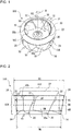
- Fig. 1 is a perspective view of a centrifugal fan 100 according to Embodiment 1 of the present disclosure.
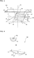
- Fig. 2 is a side view of the centrifugal fan 100 according to Embodiment 1 of the present disclosure.
- a fundamental structure of the centrifugal fan 100 will be described with reference to Figs. 1 and 2 .
- the centrifugal fan 100 is rotated by, for example, a motor (not illustrated), and is configured to force air to be sent radially outward by using a centrifugal force produced by rotation.
- the centrifugal fan 100 includes a backing plate 10, which is a rotating part, a substantially ring-shaped rim 20 facing the backing plate 10, and a plurality of blades 30 arranged between the backing plate 10 and the rim 20.
- the backing plate 10 is a rotating part that rotates about a virtual rotation axis RS.
- the backing plate 10 is circular as viewed in projection along the virtual rotation axis RS of the centrifugal fan 100.
- a radially inner portion of the backing plate 10 has a substantially conical shape, or protrudes like a mountain toward the rim 20.
- the backing plate 10 has a sloping surface that slopes from the center toward the periphery in a direction away from an air inlet 102, which will be described later.
- the backing plate 10 includes a boss 12 at the center of the backing plate 10, or the top of the mountain-like portion.
- the boss 12 is part to which a rotating shaft of the motor (not illustrated) is secured.
- the boss 12 is connected to the rotating shaft of the motor.
- the backing plate 10 is rotated about the virtual rotation axis RS by driving the motor (not illustrated).
- the virtual rotation axis RS is the virtual rotation axis of the centrifugal fan 100 as well as the virtual rotation axis of the backing plate 10.
- the backing plate 10 is a rotating part including the boss 12.
- the shape of the backing plate 10 is not limited to a substantially conical shape that is circular as viewed in projection along the virtual rotation axis RS and protrudes like a mountain.
- the backing plate 10 may have any other shape.
- the backing plate 10 may be disc-shaped or may be substantially flat and polygonal as viewed in projection along the virtual rotation axis RS.
- the backing plate 10 may be shaped such that the radially inner portion of the backing plate 10 protrudes like a mountain and a radially outer portion of the backing plate 10, or annular peripheral part of the radially inner protruding portion, is substantially flat.
- the rim 20 faces the backing plate 10.
- the rim 20 is a ring having a substantially arc-shaped section and functions as a suction guide wall.
- the rim 20 is a shroud.
- the rim 20 is ring-shaped as viewed in projection along the virtual rotation axis RS of the centrifugal fan 100.
- the rim 20 protrudes inwardly from its radially outer edge to have a mountain-like shape.
- the air inlet 102 is located at the center of the rim 20. More specifically, the rim 20 has an inner circumferential edge or end 22, which defines the air inlet 102 of the centrifugal fan 100, and has a radially inwardly curved surface such that the diameter increases from the air inlet 102 toward the backing plate 10.
- the rim 20 has an outside diameter OS, which is larger than an outside diameter OM of the backing plate 10.
- the configuration of the centrifugal fan 100 is not limited to the above-described configuration in which the outside diameter OS of the rim 20 is larger than the outside diameter OM of the backing plate 10.
- the outside diameter OS of the rim 20 may be equal to the outside diameter OM of the backing plate 10 or may be smaller than the outside diameter OM of the backing plate 10.
- the rim 20 connects the blades 30 to maintain the positional relationship of leading edges of the blades 30 and enhance the strengths of the blades 30.
- the backing plate 10 is disposed at a distance from the rim 20 in a direction along the virtual rotation axis RS.
- the centrifugal fan 100 has an air outlet 104 defined between the rim periphery 24 of the rim 20 and a backing-plate periphery 14 of the backing plate 10 such that the air outlet 104 is located between the rim periphery 24 and the backing-plate periphery 14.
- the rim periphery 24 is a radially outer end of the rim 20 and constitutes the outer circumferential edge of the rim 20.
- the backing-plate periphery 14 is a radially outer end of the backing plate 10 and constitutes an outer circumferential edge of the backing plate 10.
- the air outlet 104 is an opening through which air sucked into the centrifugal fan 100 through the air inlet 102 is discharged by rotation of the centrifugal fan 100.
- the blades 30 rotate together with the backing plate 10 during rotation of the backing plate 10 and create a current of air flowing from the center of the backing plate 10 to the periphery thereof.
- the blades 30 are arranged between the backing plate 10 and the rim 20.
- One end of each of the blades 30 in the direction along the virtual rotation axis RS of the centrifugal fan 100 is joined to the backing plate 10.
- the other end thereof is joined to the rim 20.
- the blades 30 are arranged on a circumference about the virtual rotation axis RS and are regularly spaced apart from each other along the circumference of the backing plate 10.
- the blades 30 extend rearward in a rotation direction R in which the backing plate 10 rotates.
- Each of the blades 30 has an inner edge 31 and an outer edge 32 such that the inner edge 31 is located closer to the virtual rotation axis RS than the outer edge 32.
- the inner edge 31 is a leading edge of the blade 30.
- the outer edge 32 is a trailing edge of the blade 30.
- Each of the inner edges 31 of the blades 30 is located at a predetermined distance from the virtual rotation axis RS.
- Each of the outer edges 32 is located in proximity to the backing-plate periphery 14 and the rim periphery 24.
- a virtual extension of a chord that is a straight line connecting the inner edge 31 and the outer edge 32 of each blade 30 extends so as not to pass through the virtual rotation axis RS.
- the inner edge 31 is located forward of a virtual radial line connecting the virtual rotation axis RS and the outer edge 32 in the rotation direction R.
- a blade outer surface 30a is a surface of the blade remote from the virtual rotation axis RS.
- the distance of the blade outer surface 30a from the virtual rotation axis RS increases toward the trailing edge in the rotation direction R.
- a blade inner surface 30b is a surface of the blade adjacent to the virtual rotation axis RS.
- the distance of the blade inner surface 30b from the virtual rotation axis RS increases toward the trailing edge in the rotation direction R such that a predetermined distance is kept between the blade inner surface 30b and the blade outer surface 30a.
- the blade 30 has a thickness, which corresponds to the predetermined distance, gradually decreasing from the middle of the blade 30 toward the inner edge 31 and the outer edge 32.
- the blade 30 has a cross-section in a plane perpendicular to the virtual rotation axis RS and the cross-section resembles that of a typical wing.
- a blade outside diameter OW of the centrifugal fan 100 in a region AS between the rim 20 and a middle HB of an axial opening dimension of the air outlet 104 in the direction along the virtual rotation axis RS is larger than the blade outside diameter OW at the middle HB. Furthermore, the blade outside diameter OW of the centrifugal fan 100 in a region AM between the backing plate 10 and the middle HB of the axial opening dimension of the air outlet 104 in the direction along the virtual rotation axis RS is smaller than the blade outside diameter OW at the middle HB.
- the centrifugal fan 100 has a maximum blade outside diameter OW at a position closer to the rim 20 than to the middle HB of the axial opening dimension of the air outlet 104 in the direction along the virtual rotation axis RS, and has a minimum blade outside diameter OW at a position closer to the backing plate 10 than to the middle HB of the axial opening dimension of the air outlet 104 in the direction along the virtual rotation axis RS.
- the axial opening dimension of the air outlet 104 in the direction along the virtual rotation axis RS is a distance between the backing-plate periphery 14 of the backing plate 10 and the rim periphery 24 of the rim 20 in the direction along the virtual rotation axis RS.
- the blade outside diameter OW is a diameter of a portion including the blades 30 of the centrifugal fan 100.
- the blade outside diameter OW is a diameter of a rotation circle defined by the outer edges 32 of the blades 30 during rotation of the centrifugal fan 100 while the centrifugal fan 100 is operated.
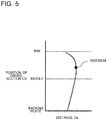
- Fig. 3 is a schematic diagram illustrating the backing plate 10, the rim 20, and one blade 30 of the centrifugal fan 100 in Fig. 2 as viewed from the side.
- Fig. 4 is a schematic diagram illustrating a cross-section CS of the blade 30 in a plane parallel to the backing plate 10 of the centrifugal fan 100 according to Embodiment 1 of the present disclosure as viewed in the direction along the virtual rotation axis RS.
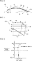
- Fig. 5 is a graph illustrating the relationship between a blade chord distance Da between the inner edge 31 and the outer edge 32 of the blade 30 at a cross-section parallel to the backing plate 10 of the centrifugal fan 100 according to Embodiment 1 of the present disclosure and the position of a cross-section CS of the blade 30.
- Fig. 3 illustrates only one blade 30 of the blades 30 and depiction of the other blades 30 is omitted to reveal the geometry of the blade 30.
- Cross-sections CS of the blade 30 in planes parallel to the backing plate 10 are defined as first cross-sections of the blade 30.
- the blade chord distance Da is defined as a linear distance between the inner edge 31 and the outer edge 32 of each of the blades 30, arranged to surround the virtual rotation axis RS of the backing plate 10, in each of the cross-sections CS of each of the blades 30 in planes parallel to the backing plate 10. Since the backing plate 10 of the centrifugal fan 100 according to Embodiment 1 of the present disclosure is substantially conical, a plane parallel to the backing plate 10 is a substantially conical plane. In Fig. 3 , broken lines illustrate the positions of cross-sections CS of the blade 30 in planes parallel to the backing plate 10.
- a cross-section CS having an intersection of the outer edge 32 with a plane F, which is perpendicular to the virtual rotation axis RS and is at the middle HB of the axial opening dimension of the air outlet 104 in the direction along the virtual rotation axis RS, is defined as a middle cross-section MS.
- the blade chord distance Da has a maximum at one of the cross-sections CS that is located closer to the rim 20 than to the middle cross-section MS.
- the blade chord distance Da between the inner edge 31 and the outer edge 32 of each blade 30 increases from the backing plate 10 toward the rim 20, reaches a maximum at a position closer to the rim 20 than to the middle HB between the backing plate 10 and the rim 20, and then decreases toward the rim 20.
- the blades 30 secured to the backing plate 10 circumferentially move about the virtual rotation axis RS.
- the rotation of the backing plate 10 in the rotation direction R causes air outside the centrifugal fan 100 to be sucked into a space defined by the backing plate 10, the rim 20, and the blades 30 through the air inlet 102.
- the blades 30 rotate together with the backing plate 10, causing the air sucked into the space defined by the backing plate 10 and the blade 30 to pass through spaces between the adjacent blades 30 and be sent outward in a radial direction of the backing plate 10.
- the blade chord distance Da has a maximum at one of the cross-sections CS that is located closer to the rim 20 than to the middle cross-section MS.
- an air flow tends to be located closer to a backing plate than to a rim.
- the blade chord distance Da of each blade 30 at a cross-section adjacent to the rim 20 is larger than that at a cross-section adjacent to the backing plate 10 such that the area of blade part adjacent to the rim 20 is larger than the area of blade part adjacent to the backing plate 10, resulting in an increase in air flow velocity in a region adjacent to the rim 20. This leads to a uniform distribution of velocity of air to be blown from the fan.
- the outside diameter defined by the blades 30 at a position adjacent to the rim 20 is larger than that at a position adjacent to the backing plate 10, thus increasing the amount of work by parts of the blades 30 that are adjacent to the rim 20.
- the uniform distribution of velocity of air to be blown from the centrifugal fan 100 results in a reduction in pressure loss in a high-velocity air flow region caused by an uneven air flow, leading to improved fan efficiency.
- the blade chord distance Da between the inner edge 31 and the outer edge 32 of each blade 30 increases from the backing plate 10 toward the rim 20, reaches a maximum at a position closer to the rim 20 than to the middle HB between the backing plate 10 and the rim 20, and then decreases toward the rim 20.
- a reduction in blade chord distance Da in a region in proximity to the rim 20 can reduce or eliminate noise that arises from a collision between turbulent air flows caused by a wake downstream of a bell mouth connected to the rim 20 and a leakage flow of air entering a gap between the bell mouth and the rim 20.
- Fig. 6 is a cross-sectional view of a blade 30 in a plane perpendicular to the virtual rotation axis RS of a centrifugal fan 100 according to Embodiment 2 of the present disclosure.
- Fig. 7 is a side schematic diagram of the centrifugal fan 100 according to Embodiment 2 of the present disclosure.
- Fig. 8 is a graph illustrating the relationship between an inlet angle ⁇ of the blade 30 of the centrifugal fan 100 according to Embodiment 2 of the present disclosure and the position of a cross-section CR.
- Fig. 9 is a cross-sectional view of the blade 30 in a plane perpendicular to the virtual rotation axis RS of the centrifugal fan 100 at a position Pb in Figs.
- Fig. 10 is a cross-sectional view of the blade 30 in a plane perpendicular to the virtual rotation axis RS of the centrifugal fan 100 at a position Pc in Figs. 7 and 8 .
- Fig. 11 is a cross-sectional view of the blade 30 in a plane perpendicular to the virtual rotation axis RS of the centrifugal fan 100 at a position Pd in Figs. 7 and 8 .
- the same components and parts as those in the centrifugal fan 100 in Figs. 1 to 5 are designated by the same reference signs and a description of these components and parts is omitted.
- the centrifugal fan 100 according to Embodiment 2 is obtained by further determining details of the geometry of each blade 30 in the centrifugal fan 100 according to Embodiment 1. The following description will focus on the geometry of each blade 30 of the centrifugal fan 100 according to Embodiment 2 of the present disclosure.
- the blade 30 of the centrifugal fan 100 according to Embodiment 2 will be described with reference to Figs. 6 to 11 .
- the inlet angle ⁇ of the blade 30 is defined as an angle formed by a center line CL of the blade 30 and a tangent TL1 to a virtual circle C1, which has a center at the virtual rotation axis RS and intersects a leading edge 35 of the blade 30, at the leading edge 35.
- the cross-sections CR of each of the blades 30 in planes perpendicular to the virtual rotation axis RS of the backing plate 10 are defined as second cross-sections of the blade 30. As illustrated in Figs.
- the inlet angle ⁇ of each blade 30 has a minimum at one of the cross-sections CR that is located closer to the rim 20 than a middle Pm of the leading edge 35 of the blade 30 between the backing plate 10 and the rim 20. More specifically, as represented by an inlet angle ⁇ 1 at the position Pb and an inlet angle ⁇ 2 at the position Pc, the inlet angle ⁇ of the blade 30 decreases from the backing plate 10 toward the rim 20 and reaches a minimum at a position closer to the rim 20 than the middle Pm between the backing plate 10 and the rim 20.
- the inlet angle ⁇ of the blade 30 increases from the position Pc with the inlet angle ⁇ 2, which is a minimum, toward the rim 20.
- the middle Pm of the leading edge 35 between the backing plate 10 and the rim 20 is the middle of a dimension along the leading edge 35 between the backing plate 10 and the rim 20.
- the inlet angle ⁇ of each blade 30 has a minimum at one of the cross-sections CR that is located closer to the rim 20 than the middle Pm of the leading edge 35 of the blade 30 between the backing plate 10 and the rim 20.
- a reduction in inlet angle ⁇ at a position closer to the rim 20 than the middle Pm reduces air flow separation at the leading edge 35 of the blade 30, resulting in an increase in air flow velocity in a region adjacent to the rim 20. This leads to a more uniform distribution of velocity of air to be blown from the fan.
- the inlet angle ⁇ of each blade 30 increases from the position Pc with the inlet angle ⁇ 2, which is a minimum, toward the rim 20.
- a leakage flow of air entering a gap between a rim 20 and a bell mouth connected to the rim 20 is likely to occur in proximity to the rim 20.
- Such a leakage air flow which includes a component rotating in the rotation direction R of the centrifugal fan 100, enters the centrifugal fan.
- an increase in inlet angle ⁇ at a position in proximity to the rim 20 can reduce or eliminate a pressure loss caused by air flow separation at the leading edge 35 of each blade 30.
- Fig. 12 is a cross-sectional view of a blade 30 in a plane perpendicular to the virtual rotation axis RS of a centrifugal fan 100 according to Embodiment 3 of the present disclosure.
- Fig. 13 is a graph illustrating the relationship between a camber height H of the blade 30 of the centrifugal fan 100 according to Embodiment 3 of the present disclosure and the position of a cross-section CR.
- the same components and parts as those in the centrifugal fans 100 in Figs. 1 to 11 are designated by the same reference signs and a description of these components and parts is omitted.
- the centrifugal fan 100 according to Embodiment 3 is obtained by further determining details of the geometry of each blade 30 in the centrifugal fan 100 according to Embodiment 1 or Embodiment 2. The following description will focus on the geometry of each blade 30 of the centrifugal fan 100 according to Embodiment 3 of the present disclosure. The geometry of the blade 30 of the centrifugal fan 100 according to Embodiment 3 will be described with reference to Figs. 12 and 13 .
- the camber height H is defined as a perpendicular distance from the center line CL of each blade 30 to a straight line SL connecting the leading edge 35 and a trailing edge 36 of the blade 30 in each cross-section CR of the blade 30 in a plane perpendicular to the virtual rotation axis RS.
- the camber height H is zero at the leading edge 35 of the blade 30 and the trailing edge 36 of the blade 30.
- the cross-section CR of the blade 30 includes an outer curve having a large curvature and an inner curve having a small curvature or a straight line.
- a maximum camber height H is located closer to the trailing edge 36 than a midpoint CM of a linear distance between the leading edge 35 and the trailing edge 36.
- the term “outer” refers to being adjacent to the trailing edge 36 and the term “inner” refers to being adjacent to the leading edge 35.
- the camber height H of each blade 30 has a maximum at one of the cross-sections CR that is located closer to the rim 20 than to the middle Pm of the leading edge 35 of the blade 30 between the backing plate 10 and the rim 20.
- the maximum camber height Ha of the entire blade 30 is located closer to the rim 20 than to the middle Pm between the backing plate 10 and the rim 20.
- the camber height H of the blade 30 increases from the backing plate 10 toward the rim 20 and reaches a maximum at a position closer to the rim 20 than to the middle Pm between the backing plate 10 and the rim 20. Then, the camber height H of the blade 30 decreases from the position of the cross-section CR with the maximum camber height toward the rim 20.
- the camber height H of each blade 30 of the centrifugal fan 100 has a maximum at one of the cross-sections CR that is located closer to the rim 20 than to the middle Pm between the backing plate 10 and the rim 20.
- the camber height H at a position closer to the rim 20 than to the middle Pm between the backing plate 10 and the rim 20 is larger than that at the middle Pm, thus increasing the amount of work by parts of the blades that are adjacent to the rim 20. This results in an increase in air flow velocity in a region adjacent to the rim 20, leading to a more uniform distribution of velocity of air to be blown from the fan.
- the camber height H of each blade 30 in the centrifugal fan 100 according to Embodiment 3 of the present disclosure decreases from the position of the cross-section CR with the maximum camber height toward the rim 20.
- a region in proximity to the rim 20 of the centrifugal fan 100 according to Embodiment 3 of the present disclosure tends to experience air flow separation because the blade chord distance Da between the inner edge 31 and the outer edge 32 of each blade 30 decreases in this region.
- a reduction in camber height H can reduce air flow separation.
- Fig. 14 is a cross-sectional view of a blade 30 in a plane perpendicular to the virtual rotation axis RS of a centrifugal fan 100 according to Embodiment 4 of the present disclosure.
- Fig. 15 is a side schematic diagram of the centrifugal fan 100 according to Embodiment 4 of the present disclosure.
- Fig. 16 is a graph illustrating the relationship between an outlet angle ⁇ of the blade 30 of the centrifugal fan 100 according to Embodiment 4 of the present disclosure and the position of a cross-section CR.
- Fig. 17 is a cross-sectional view of the blade 30 in a plane perpendicular to the virtual rotation axis RS of the centrifugal fan 100 at a position Pe in Figs.
- Fig. 18 is a cross-sectional view of the blade 30 in a plane perpendicular to the virtual rotation axis RS of the centrifugal fan 100 at a position Pf in Figs. 15 and 16 .
- Fig. 19 is a cross-sectional view of the blade 30 in a plane perpendicular to the virtual rotation axis RS of the centrifugal fan 100 at a position Pg in Figs. 15 and 16 .
- the same components and parts as those in the centrifugal fans 100 in Figs. 1 to 13 are designated by the same reference signs and a description of these components and parts is omitted.
- the centrifugal fan 100 according to Embodiment 4 is obtained by further determining details of the geometry of each blade 30 in the centrifugal fan 100 according to Embodiment 1. The following description will focus on the geometry of each blade 30 of the centrifugal fan 100 according to Embodiment 4 of the present disclosure.
- the blade 30 of the centrifugal fan 100 according to Embodiment 4 will be described with reference to Figs. 14 to 19 .
- the outlet angle ⁇ of the blade 30 is defined as an angle formed by the center line CL of the blade 30 and a tangent TL2 to a virtual circle C2, which has a center at the virtual rotation axis RS and intersects the trailing edge 36 of the blade 30, at the trailing edge 36.
- the outlet angle ⁇ of the blade 30 increases from the backing plate 10 toward the rim 20 as represented by an outlet angle ⁇ 1 at the position Pe, an outlet angle ⁇ 2 at the position Pf, and an outlet angle ⁇ 3 at the position Pg.
- the outlet angle ⁇ of each blade 30 at one of the cross-sections CR that is located closer to the rim 20 than to the middle Pf of the trailing edge 36 of the blade 30 between the backing plate 10 and the rim 20 is larger than the outlet angle ⁇ thereof at one of the cross-sections CR that is located closer to the backing plate 10 than to the middle Pf.
- the middle Pf of the trailing edge 36 between the backing plate 10 and the rim 20 is the middle of a dimension along the trailing edge 36 between the backing plate 10 and the rim 20.
- the outlet angle ⁇ of each blade 30 increases from the backing plate 10 toward the rim 20.
- the outlet angle ⁇ at a position adjacent to the rim 20 is larger than that at a position adjacent to the backing plate 10, thus increasing the amount of work by parts of the blades 30 that are adjacent to the rim 20. This results in an increase in air flow velocity in a region adjacent to the rim 20, leading to a more uniform distribution of velocity of air to be blown from the fan.
- the outside diameter defined by the blades at a position adjacent to the rim 20 is larger than that at a position adjacent to the backing plate 10, resulting in an increase in air flow in a region adjacent to the rim 20. Therefore, air flow separation from the blade surfaces can be reduced even though the outlet angle ⁇ increases toward the rim 20.
- Fig. 20 is a sectional view of the air-conditioning apparatus 200, which includes the centrifugal fan 100, according to Embodiment 5 of the present disclosure.
- the air-conditioning apparatus 200 is of a floor-standing type.
- the type of air-conditioning apparatus 200 is not limited to the floor-standing type.
- the air-conditioning apparatus 200 may be of any other type, such as a ceiling concealed type.
- the air-conditioning apparatus 200 includes a casing 210, which constitutes a shell of the air-conditioning apparatus 200, a heat exchanger 220 disposed in the casing 210, and the centrifugal fan 100 disposed in the casing 210 and configured to create a current of air passing through the heat exchanger 220.
- the casing 210 has a rectangular cuboid shape.
- the shape of the casing 210 is not limited to a rectangular cuboid shape.
- the casing 210 may have any other shape, such as a cylindrical shape, a rectangular columnar shape, a conical shape, a shape with multiple corners, or a shape with multiple curved surfaces.
- the casing 210 has an upper surface 211 having an air inlet 212.
- the casing 210 has a lower surface 213 having an air outlet 214.
- the air inlet 212 is an opening through which air is sucked into the casing 210 from the outside by operation of the centrifugal fan 100.
- the air outlet 214 is an opening though which air is discharged from the casing 210 to the outside by operation of the centrifugal fan 100.
- the positions of the air inlet 212 and the air outlet 214 are not limited to those in the above-described configuration.
- the air inlet 212 and the air outlet 214 may be located in the same surface.
- either one of the air inlet 212 and the air outlet 214 may be located in one side.
- the casing 210 contains the centrifugal fan 100 and the heat exchanger 220.
- An internal space of the casing 210 is divided into a space S11 containing the heat exchanger 220 and a space S12 containing the centrifugal fan 100 by a partition 215.
- the casing 210 contains electric equipment 250 for control of the air-conditioning apparatus 200.
- the centrifugal fan 100 creates a current of air such that the air is sucked into the casing 210 through the air inlet 212 of the casing 210 and is then blown to an air-conditioned space through the air outlet 214 of the casing 210.
- the centrifugal fan 100 has a bell mouth 230.
- the bell mouth 230 is disposed between the partition 215 and the centrifugal fan 100.
- the centrifugal fan 100 is connected to a motor 240.
- the motor 240 is supported by a motor support 241 secured to the lower surface 213 of the casing 210.
- the motor 240 includes an output shaft 242.
- the boss 12 of the centrifugal fan 100 is attached to the output shaft 242 of the motor 240.
- the number of centrifugal fans 100 in the casing 210 is not limited to one. Multiple centrifugal fans may be arranged in the casing.
- the heat exchanger 220 is disposed upstream of the centrifugal fan 100 in an air flow direction in which the air current created by the centrifugal fan 100 flows in the casing 210.
- the heat exchanger 220 adjusts the temperature of air that is sucked into the casing 210 through the air inlet 212 of the casing 210 and is then blown to the air-conditioned space through the air outlet 214.
- the heat exchanger 220 having a known structure can be used.
- a removable filter 221 is disposed upstream of the heat exchanger 220 in the air flow direction in which the air current created by the centrifugal fan 100 flows in the casing 210.
- the filter 221 removes dust from air that is to pass through the heat exchanger 220.
- a drain pan 222 to collect condensate water is disposed under the heat exchanger 220.
- the air-conditioning apparatus 200 includes any one of the centrifugal fans 100 according to Embodiments 1 to 4. Such a configuration can provide a uniform distribution of velocity of air to be blown, leading to improved fan efficiency. Furthermore, this configuration, in which any one of the centrifugal fans 100 according to Embodiments 1 to 4 is included, can reduce or eliminate noise that arises from a collision between turbulent air flows caused by a wake downstream of the bell mouth and a leakage flow of air entering the gap between the bell mouth and the rim 20.
Landscapes
- Engineering & Computer Science (AREA)
- Mechanical Engineering (AREA)
- General Engineering & Computer Science (AREA)
- Structures Of Non-Positive Displacement Pumps (AREA)
Abstract
Description
- The present disclosure relates to a centrifugal fan that changes the direction of flow of air sucked from a rim in a direction along a virtual rotation axis to a radial direction and blows the air radially and an air-conditioning apparatus including the centrifugal fan.
- A developed centrifugal fan is configured such that an outside diameter defined by blades at a position closer to a backing plate than to the midpoint of a distance between the backing plate and a rim in a direction along a virtual rotation axis in an air outlet of the centrifugal fan is smaller than an outside diameter defined by the blades at a position closer to the rim than to the midpoint of the distance (refer to Patent Literature 1, for example).
- Patent Literature 1:
Japanese Unexamined Patent Application Publication No. 2015-212547 - Atypical centrifugal fan incudes a backing plate having a boss connected to a rotating shaft of a motor, a rim functioning as a suction guide wall, and a plurality of blades arranged between the backing plate and the rim, and has a structure in which air is sucked in a direction along the rotating shaft, the direction of flow of the air is changed to the radial direction, and the air is blown radially out of the fan. While the centrifugal fan is driven, an air flow tends to be located closer to the backing plate than to the midpoint of a distance between the backing plate and the rim in the direction along the rotating shaft in an air outlet of the centrifugal fan, causing a pressure loss due to a high-velocity air flow in a region adjacent to the backing plate. This tends to lead to lower fan efficiency. The centrifugal fan has the property that the above-described tendency is notably observed when the centrifugal fan is installed in an air passage with a low air flow resistance. Furthermore, an air flow in the centrifugal fan does not tend to be located closer to the rim than to the midpoint of the distance between the backing plate and the rim in the direction along the rotating shaft in the air outlet of the centrifugal fan. Therefore, the amount of work by parts of the blades that are adjacent to the rim is smaller than that adjacent to the backing plate. For the centrifugal fan disclosed in Patent Literature 1, an outside diameter defined by the blades at a position closer to the rim than to the midpoint of the distance between the backing plate and the rim in a direction along the virtual rotation axis in the air outlet of the centrifugal fan is larger than an outside diameter defined by the blades at a position closer to the backing plate than to the midpoint of the distance between the backing plate and the rim in the direction along the virtual rotation axis in the air outlet. This allows for a relative increase in the amount of work by parts of the blades that are adjacent to the rim. However, this increase is not enough to provide a uniform distribution of velocity of air to be blown from the fan.
- The present disclosure is intended to solve the above-described problem and aims to provide a centrifugal fan with a uniform distribution of velocity of air to be blown and an air-conditioning apparatus including the centrifugal fan.
- An embodiment of the present disclosure provides a centrifugal fan including: a backing plate to be rotated, a ring-shaped rim facing the backing plate, and a plurality of blades arranged to surround a virtual rotation axis of the backing plate, the plurality of blades being arranged between the backing plate and the rim and each having an inner edge and an outer edge, wherein a blade chord distance has a maximum at one of first cross-sections that is located closer to the rim than to a middle cross-section where the first cross-sections are cross-sections of each of the plurality of blades in planes parallel to the backing plate, the blade chord distance is a linear distance between the inner edge and the outer edge of each of the plurality of blades in each of the first cross-sections, and the middle cross-section is one of the first cross-sections that has an intersection of the outer edge with a plane perpendicular to the virtual rotation axis, the plane being at a middle of an axial opening dimension of an air outlet defined between a periphery of the rim and a periphery of the backing plate, the axial opening dimension being defined as a dimension along the virtual rotation axis.
- In the centrifugal fan according to the embodiment of the present disclosure, the blade chord distance has a maximum at one of the first cross-sections that is located closer to the rim than to the middle cross-section, which is one of the first cross-sections that has an intersection of the outer edge with a plane perpendicular to the virtual rotation axis, the plane being at the middle of the axial opening dimension of the air outlet in a direction along the virtual rotation axis. In a typical centrifugal fan, an air flow tends to be located closer to a backing plate than to a rim. In contrast, in the centrifugal fan according to the embodiment of the present disclosure, the blade chord distance at a cross-section adjacent to the rim is larger than that at a cross-section adjacent to the backing plate, thus making the area of parts of the blades that are adjacent to the rim larger than the area of parts of the blades that are adjacent to the backing plate. This results in an increase in air flow velocity in a region adjacent to the rim, leading to a uniform distribution of velocity of air to be blown from the fan.
-
- [
Fig. 1] Fig. 1 is a perspective view of a centrifugal fan according to Embodiment 1 of the present disclosure. - [
Fig. 2] Fig. 2 is a side view of the centrifugal fan according to Embodiment 1 of the present disclosure. - [
Fig. 3] Fig. 3 is a schematic diagram illustrating a backing plate, a rim, and one blade of the centrifugal fan inFig. 2 as viewed from the side. - [
Fig. 4] Fig. 4 is a schematic diagram illustrating a cross-section of the blade in a plane parallel to the backing plate of the centrifugal fan according to Embodiment 1 of the present disclosure as viewed in a direction along a virtual rotation axis. - [
Fig. 5] Fig. 5 is a graph illustrating the relationship between a blade chord distance between an inner edge and an outer edge of the blade at a cross-section parallel to the backing plate of the centrifugal fan according to Embodiment 1 of the present disclosure and the position of a cross-section of the blade. - [
Fig. 6] Fig. 6 is a cross-sectional view of a blade in a plane perpendicular to the virtual rotation axis of a centrifugal fan according to Embodiment 2 of the present disclosure. - [
Fig. 7] Fig. 7 is a side schematic diagram of the centrifugal fan according to Embodiment 2 of the present disclosure. - [
Fig. 8] Fig. 8 is a graph illustrating the relationship between an inlet angle of the blade of the centrifugal fan according to Embodiment 2 of the present disclosure and the position of a cross-section CR. - [
Fig. 9] Fig. 9 is a cross-sectional view of the blade in a plane perpendicular to the virtual rotation axis of the centrifugal fan at a position Pb inFigs. 7 and 8 . - [
Fig. 10] Fig. 10 is a cross-sectional view of the blade in a plane perpendicular to the virtual rotation axis of the centrifugal fan at a position Pc inFigs. 7 and 8 . - [
Fig. 11] Fig. 11 is a cross-sectional view of the blade in a plane perpendicular to the virtual rotation axis of the centrifugal fan at a position Pd inFigs. 7 and 8 . - [
Fig. 12] Fig. 12 is a cross-sectional view of a blade in a plane perpendicular to the virtual rotation axis of a centrifugal fan according toEmbodiment 3 of the present disclosure. - [
Fig. 13] Fig. 13 is a graph illustrating the relationship between a camber height of the blade in the centrifugal fan according toEmbodiment 3 of the present disclosure and the position of a cross-section CR. - [
Fig. 14] Fig. 14 is a cross-sectional view of a blade in a plane perpendicular to the virtual rotation axis of a centrifugal fan according to Embodiment 4 of the present disclosure. - [
Fig. 15] Fig. 15 is a side schematic diagram of the centrifugal fan according to Embodiment 4 of the present disclosure. - [
Fig. 16] Fig. 16 is a graph illustrating the relationship between an outlet angle of the blade in the centrifugal fan according to Embodiment 4 of the present disclosure and the position of a cross-section CR. - [
Fig. 17] Fig. 17 is a cross-sectional view of the blade in a plane perpendicular to the virtual rotation axis of the centrifugal fan at a position Pe inFigs. 15 and 16 . - [
Fig. 18] Fig. 18 is a cross-sectional view of the blade in a plane perpendicular to the virtual rotation axis of the centrifugal fan at a position Pf inFigs. 15 and 16 . - [
Fig. 19] Fig. 19 is a cross-sectional view of the blade in a plane perpendicular to the virtual rotation axis of the centrifugal fan at a position Pg inFigs. 15 and 16 . - [
Fig. 20] Fig. 20 is a sectional view of an air-conditioning apparatus, which includes any of the above centrifugal fans, according to Embodiment 5 of the present disclosure. - A
centrifugal fan 100 and an air-conditioning apparatus 200 according to embodiments of the present disclosure will be described below with reference to the drawings. Note that the relationship between the sizes of components in the following drawings includingFig. 1 may differ from that between the actual sizes of the components. Furthermore, note that components designated by the same reference signs in the following drawings are the same components or equivalents. This note applies to the entire description herein. For the sake of clarity, terms representing directions, such as "upper", "lower", "rightward", "leftward", "front", and "rear", will be used as appropriate. These terms are used herein only for the purpose of convenience of description and are not intended to restrict the location and orientation of the apparatus or part. -
Fig. 1 is a perspective view of acentrifugal fan 100 according to Embodiment 1 of the present disclosure.Fig. 2 is a side view of thecentrifugal fan 100 according to Embodiment 1 of the present disclosure. A fundamental structure of thecentrifugal fan 100 will be described with reference toFigs. 1 and 2 . Thecentrifugal fan 100 is rotated by, for example, a motor (not illustrated), and is configured to force air to be sent radially outward by using a centrifugal force produced by rotation. Thecentrifugal fan 100 includes abacking plate 10, which is a rotating part, a substantially ring-shaped rim 20 facing thebacking plate 10, and a plurality ofblades 30 arranged between thebacking plate 10 and therim 20. - The
backing plate 10 is a rotating part that rotates about a virtual rotation axis RS. Thebacking plate 10 is circular as viewed in projection along the virtual rotation axis RS of thecentrifugal fan 100. A radially inner portion of thebacking plate 10 has a substantially conical shape, or protrudes like a mountain toward therim 20. In other words, thebacking plate 10 has a sloping surface that slopes from the center toward the periphery in a direction away from anair inlet 102, which will be described later. Thebacking plate 10 includes aboss 12 at the center of thebacking plate 10, or the top of the mountain-like portion. Theboss 12 is part to which a rotating shaft of the motor (not illustrated) is secured. Theboss 12 is connected to the rotating shaft of the motor. Thebacking plate 10 is rotated about the virtual rotation axis RS by driving the motor (not illustrated). The virtual rotation axis RS is the virtual rotation axis of thecentrifugal fan 100 as well as the virtual rotation axis of thebacking plate 10. - It is only required that the
backing plate 10 is a rotating part including theboss 12. The shape of thebacking plate 10 is not limited to a substantially conical shape that is circular as viewed in projection along the virtual rotation axis RS and protrudes like a mountain. Thebacking plate 10 may have any other shape. For example, thebacking plate 10 may be disc-shaped or may be substantially flat and polygonal as viewed in projection along the virtual rotation axis RS. Furthermore, thebacking plate 10 may be shaped such that the radially inner portion of thebacking plate 10 protrudes like a mountain and a radially outer portion of thebacking plate 10, or annular peripheral part of the radially inner protruding portion, is substantially flat. - The
rim 20 faces thebacking plate 10. Therim 20 is a ring having a substantially arc-shaped section and functions as a suction guide wall. Therim 20 is a shroud. Therim 20 is ring-shaped as viewed in projection along the virtual rotation axis RS of thecentrifugal fan 100. Therim 20 protrudes inwardly from its radially outer edge to have a mountain-like shape. Theair inlet 102 is located at the center of therim 20. More specifically, therim 20 has an inner circumferential edge or end 22, which defines theair inlet 102 of thecentrifugal fan 100, and has a radially inwardly curved surface such that the diameter increases from theair inlet 102 toward thebacking plate 10. Arim periphery 24, which constitutes an outer circumferential edge of the ring-shapedrim 20, has a larger diameter than any other portion of therim 20 and is located closest to thebacking plate 10. Therim 20 has an outside diameter OS, which is larger than an outside diameter OM of thebacking plate 10. The configuration of thecentrifugal fan 100 is not limited to the above-described configuration in which the outside diameter OS of therim 20 is larger than the outside diameter OM of thebacking plate 10. The outside diameter OS of therim 20 may be equal to the outside diameter OM of thebacking plate 10 or may be smaller than the outside diameter OM of thebacking plate 10. Therim 20 connects theblades 30 to maintain the positional relationship of leading edges of theblades 30 and enhance the strengths of theblades 30. - The
backing plate 10 is disposed at a distance from therim 20 in a direction along the virtual rotation axis RS. Thecentrifugal fan 100 has anair outlet 104 defined between therim periphery 24 of therim 20 and a backing-plate periphery 14 of thebacking plate 10 such that theair outlet 104 is located between therim periphery 24 and the backing-plate periphery 14. Therim periphery 24 is a radially outer end of therim 20 and constitutes the outer circumferential edge of therim 20. The backing-plate periphery 14 is a radially outer end of thebacking plate 10 and constitutes an outer circumferential edge of thebacking plate 10. Theair outlet 104 is an opening through which air sucked into thecentrifugal fan 100 through theair inlet 102 is discharged by rotation of thecentrifugal fan 100. - The
blades 30 rotate together with thebacking plate 10 during rotation of thebacking plate 10 and create a current of air flowing from the center of thebacking plate 10 to the periphery thereof. Theblades 30 are arranged between thebacking plate 10 and therim 20. One end of each of theblades 30 in the direction along the virtual rotation axis RS of thecentrifugal fan 100 is joined to thebacking plate 10. The other end thereof is joined to therim 20. Theblades 30 are arranged on a circumference about the virtual rotation axis RS and are regularly spaced apart from each other along the circumference of thebacking plate 10. Theblades 30 extend rearward in a rotation direction R in which thebacking plate 10 rotates. - Each of the
blades 30 has aninner edge 31 and anouter edge 32 such that theinner edge 31 is located closer to the virtual rotation axis RS than theouter edge 32. Theinner edge 31 is a leading edge of theblade 30. Theouter edge 32 is a trailing edge of theblade 30. Each of theinner edges 31 of theblades 30 is located at a predetermined distance from the virtual rotation axis RS. Each of theouter edges 32 is located in proximity to the backing-plate periphery 14 and therim periphery 24. A virtual extension of a chord that is a straight line connecting theinner edge 31 and theouter edge 32 of eachblade 30 extends so as not to pass through the virtual rotation axis RS. In other words, theinner edge 31 is located forward of a virtual radial line connecting the virtual rotation axis RS and theouter edge 32 in the rotation direction R. - A blade
outer surface 30a is a surface of the blade remote from the virtual rotation axis RS. The distance of the bladeouter surface 30a from the virtual rotation axis RS increases toward the trailing edge in the rotation direction R. A bladeinner surface 30b is a surface of the blade adjacent to the virtual rotation axis RS. Similarly, the distance of the bladeinner surface 30b from the virtual rotation axis RS increases toward the trailing edge in the rotation direction R such that a predetermined distance is kept between the bladeinner surface 30b and the bladeouter surface 30a. Theblade 30 has a thickness, which corresponds to the predetermined distance, gradually decreasing from the middle of theblade 30 toward theinner edge 31 and theouter edge 32. In other words, theblade 30 has a cross-section in a plane perpendicular to the virtual rotation axis RS and the cross-section resembles that of a typical wing. - As illustrated in
Fig. 2 , a blade outside diameter OW of thecentrifugal fan 100 in a region AS between therim 20 and a middle HB of an axial opening dimension of theair outlet 104 in the direction along the virtual rotation axis RS is larger than the blade outside diameter OW at the middle HB. Furthermore, the blade outside diameter OW of thecentrifugal fan 100 in a region AM between thebacking plate 10 and the middle HB of the axial opening dimension of theair outlet 104 in the direction along the virtual rotation axis RS is smaller than the blade outside diameter OW at the middle HB. Thecentrifugal fan 100 has a maximum blade outside diameter OW at a position closer to therim 20 than to the middle HB of the axial opening dimension of theair outlet 104 in the direction along the virtual rotation axis RS, and has a minimum blade outside diameter OW at a position closer to thebacking plate 10 than to the middle HB of the axial opening dimension of theair outlet 104 in the direction along the virtual rotation axis RS. The axial opening dimension of theair outlet 104 in the direction along the virtual rotation axis RS is a distance between the backing-plate periphery 14 of thebacking plate 10 and therim periphery 24 of therim 20 in the direction along the virtual rotation axis RS. The blade outside diameter OW is a diameter of a portion including theblades 30 of thecentrifugal fan 100. In other words, the blade outside diameter OW is a diameter of a rotation circle defined by theouter edges 32 of theblades 30 during rotation of thecentrifugal fan 100 while thecentrifugal fan 100 is operated. -
Fig. 3 is a schematic diagram illustrating thebacking plate 10, therim 20, and oneblade 30 of thecentrifugal fan 100 inFig. 2 as viewed from the side.Fig. 4 is a schematic diagram illustrating a cross-section CS of theblade 30 in a plane parallel to thebacking plate 10 of thecentrifugal fan 100 according to Embodiment 1 of the present disclosure as viewed in the direction along the virtual rotation axis RS.Fig. 5 is a graph illustrating the relationship between a blade chord distance Da between theinner edge 31 and theouter edge 32 of theblade 30 at a cross-section parallel to thebacking plate 10 of thecentrifugal fan 100 according to Embodiment 1 of the present disclosure and the position of a cross-section CS of theblade 30. The geometry of theblade 30 will be further described with reference toFigs. 3 to 5 .Fig. 3 illustrates only oneblade 30 of theblades 30 and depiction of theother blades 30 is omitted to reveal the geometry of theblade 30. Cross-sections CS of theblade 30 in planes parallel to thebacking plate 10 are defined as first cross-sections of theblade 30. - As illustrated in
Figs. 3 and 4 , the blade chord distance Da is defined as a linear distance between theinner edge 31 and theouter edge 32 of each of theblades 30, arranged to surround the virtual rotation axis RS of thebacking plate 10, in each of the cross-sections CS of each of theblades 30 in planes parallel to thebacking plate 10. Since thebacking plate 10 of thecentrifugal fan 100 according to Embodiment 1 of the present disclosure is substantially conical, a plane parallel to thebacking plate 10 is a substantially conical plane. InFig. 3 , broken lines illustrate the positions of cross-sections CS of theblade 30 in planes parallel to thebacking plate 10. Furthermore, a cross-section CS having an intersection of theouter edge 32 with a plane F, which is perpendicular to the virtual rotation axis RS and is at the middle HB of the axial opening dimension of theair outlet 104 in the direction along the virtual rotation axis RS, is defined as a middle cross-section MS. In thecentrifugal fan 100, the blade chord distance Da has a maximum at one of the cross-sections CS that is located closer to therim 20 than to the middle cross-section MS. In thecentrifugal fan 100, the blade chord distance Da between theinner edge 31 and theouter edge 32 of eachblade 30 increases from thebacking plate 10 toward therim 20, reaches a maximum at a position closer to therim 20 than to the middle HB between thebacking plate 10 and therim 20, and then decreases toward therim 20. - When the
backing plate 10 of thecentrifugal fan 100 is rotated by rotation of the motor connected to theboss 12, theblades 30 secured to thebacking plate 10 circumferentially move about the virtual rotation axis RS. The rotation of thebacking plate 10 in the rotation direction R causes air outside thecentrifugal fan 100 to be sucked into a space defined by thebacking plate 10, therim 20, and theblades 30 through theair inlet 102. In thecentrifugal fan 100, theblades 30 rotate together with thebacking plate 10, causing the air sucked into the space defined by thebacking plate 10 and theblade 30 to pass through spaces between theadjacent blades 30 and be sent outward in a radial direction of thebacking plate 10. - In the
centrifugal fan 100, the blade chord distance Da has a maximum at one of the cross-sections CS that is located closer to therim 20 than to the middle cross-section MS. In a typical centrifugal fan, an air flow tends to be located closer to a backing plate than to a rim. In contrast, in thecentrifugal fan 100, the blade chord distance Da of eachblade 30 at a cross-section adjacent to therim 20 is larger than that at a cross-section adjacent to thebacking plate 10 such that the area of blade part adjacent to therim 20 is larger than the area of blade part adjacent to thebacking plate 10, resulting in an increase in air flow velocity in a region adjacent to therim 20. This leads to a uniform distribution of velocity of air to be blown from the fan. In addition, the outside diameter defined by theblades 30 at a position adjacent to therim 20 is larger than that at a position adjacent to thebacking plate 10, thus increasing the amount of work by parts of theblades 30 that are adjacent to therim 20. This results in an increase in air flow velocity, leading to a more uniform distribution of velocity of air to be blown from the fan. The uniform distribution of velocity of air to be blown from thecentrifugal fan 100 results in a reduction in pressure loss in a high-velocity air flow region caused by an uneven air flow, leading to improved fan efficiency. - Additionally, in the
centrifugal fan 100, the blade chord distance Da between theinner edge 31 and theouter edge 32 of eachblade 30 increases from thebacking plate 10 toward therim 20, reaches a maximum at a position closer to therim 20 than to the middle HB between thebacking plate 10 and therim 20, and then decreases toward therim 20. In thecentrifugal fan 100, a reduction in blade chord distance Da in a region in proximity to therim 20 can reduce or eliminate noise that arises from a collision between turbulent air flows caused by a wake downstream of a bell mouth connected to therim 20 and a leakage flow of air entering a gap between the bell mouth and therim 20. -
Fig. 6 is a cross-sectional view of ablade 30 in a plane perpendicular to the virtual rotation axis RS of acentrifugal fan 100 according to Embodiment 2 of the present disclosure.Fig. 7 is a side schematic diagram of thecentrifugal fan 100 according to Embodiment 2 of the present disclosure.Fig. 8 is a graph illustrating the relationship between an inlet angle α of theblade 30 of thecentrifugal fan 100 according to Embodiment 2 of the present disclosure and the position of a cross-section CR.Fig. 9 is a cross-sectional view of theblade 30 in a plane perpendicular to the virtual rotation axis RS of thecentrifugal fan 100 at a position Pb inFigs. 7 and 8 .Fig. 10 is a cross-sectional view of theblade 30 in a plane perpendicular to the virtual rotation axis RS of thecentrifugal fan 100 at a position Pc inFigs. 7 and 8 .Fig. 11 is a cross-sectional view of theblade 30 in a plane perpendicular to the virtual rotation axis RS of thecentrifugal fan 100 at a position Pd inFigs. 7 and 8 . The same components and parts as those in thecentrifugal fan 100 inFigs. 1 to 5 are designated by the same reference signs and a description of these components and parts is omitted. Thecentrifugal fan 100 according to Embodiment 2 is obtained by further determining details of the geometry of eachblade 30 in thecentrifugal fan 100 according to Embodiment 1. The following description will focus on the geometry of eachblade 30 of thecentrifugal fan 100 according to Embodiment 2 of the present disclosure. Theblade 30 of thecentrifugal fan 100 according to Embodiment 2 will be described with reference toFigs. 6 to 11 . - As illustrated in
Fig. 6 , in each cross-section CR of each of theblades 30 in a plane perpendicular to the virtual rotation axis RS of thebacking plate 10, the inlet angle α of theblade 30 is defined as an angle formed by a center line CL of theblade 30 and a tangent TL1 to a virtual circle C1, which has a center at the virtual rotation axis RS and intersects aleading edge 35 of theblade 30, at theleading edge 35. The cross-sections CR of each of theblades 30 in planes perpendicular to the virtual rotation axis RS of thebacking plate 10 are defined as second cross-sections of theblade 30. As illustrated inFigs. 7 to 11 , the inlet angle α of eachblade 30 has a minimum at one of the cross-sections CR that is located closer to therim 20 than a middle Pm of the leadingedge 35 of theblade 30 between thebacking plate 10 and therim 20. More specifically, as represented by an inlet angle α1 at the position Pb and an inlet angle α2 at the position Pc, the inlet angle α of theblade 30 decreases from thebacking plate 10 toward therim 20 and reaches a minimum at a position closer to therim 20 than the middle Pm between thebacking plate 10 and therim 20. As represented by the inlet angle α2 at the position Pc and an inlet angle α3 at the position Pd, the inlet angle α of theblade 30 increases from the position Pc with the inlet angle α2, which is a minimum, toward therim 20. The middle Pm of the leadingedge 35 between thebacking plate 10 and therim 20 is the middle of a dimension along the leadingedge 35 between thebacking plate 10 and therim 20. - In the
centrifugal fan 100 according to Embodiment 2 of the present disclosure, the inlet angle α of eachblade 30 has a minimum at one of the cross-sections CR that is located closer to therim 20 than the middle Pm of the leadingedge 35 of theblade 30 between thebacking plate 10 and therim 20. In thecentrifugal fan 100, a reduction in inlet angle α at a position closer to therim 20 than the middle Pm reduces air flow separation at theleading edge 35 of theblade 30, resulting in an increase in air flow velocity in a region adjacent to therim 20. This leads to a more uniform distribution of velocity of air to be blown from the fan. - Furthermore, in the
centrifugal fan 100 according to Embodiment 2 of the present disclosure, the inlet angle α of eachblade 30 increases from the position Pc with the inlet angle α2, which is a minimum, toward therim 20. In a typical centrifugal fan, a leakage flow of air entering a gap between arim 20 and a bell mouth connected to therim 20 is likely to occur in proximity to therim 20. Such a leakage air flow, which includes a component rotating in the rotation direction R of thecentrifugal fan 100, enters the centrifugal fan. In thecentrifugal fan 100, therefore, an increase in inlet angle α at a position in proximity to therim 20 can reduce or eliminate a pressure loss caused by air flow separation at theleading edge 35 of eachblade 30. -
Fig. 12 is a cross-sectional view of ablade 30 in a plane perpendicular to the virtual rotation axis RS of acentrifugal fan 100 according toEmbodiment 3 of the present disclosure.Fig. 13 is a graph illustrating the relationship between a camber height H of theblade 30 of thecentrifugal fan 100 according toEmbodiment 3 of the present disclosure and the position of a cross-section CR. The same components and parts as those in thecentrifugal fans 100 inFigs. 1 to 11 are designated by the same reference signs and a description of these components and parts is omitted. Thecentrifugal fan 100 according toEmbodiment 3 is obtained by further determining details of the geometry of eachblade 30 in thecentrifugal fan 100 according to Embodiment 1 or Embodiment 2. The following description will focus on the geometry of eachblade 30 of thecentrifugal fan 100 according toEmbodiment 3 of the present disclosure. The geometry of theblade 30 of thecentrifugal fan 100 according toEmbodiment 3 will be described with reference toFigs. 12 and 13 . - As illustrated in
Fig. 12 , the camber height H is defined as a perpendicular distance from the center line CL of eachblade 30 to a straight line SL connecting the leadingedge 35 and a trailingedge 36 of theblade 30 in each cross-section CR of theblade 30 in a plane perpendicular to the virtual rotation axis RS. The camber height H is zero at theleading edge 35 of theblade 30 and the trailingedge 36 of theblade 30. As illustrated inFig. 12 , the cross-section CR of theblade 30 includes an outer curve having a large curvature and an inner curve having a small curvature or a straight line. A maximum camber height H, or maximum camber height Ha, is located closer to the trailingedge 36 than a midpoint CM of a linear distance between theleading edge 35 and the trailingedge 36. For the cross-section CR of theblade 30, the term "outer" refers to being adjacent to the trailingedge 36 and the term "inner" refers to being adjacent to the leadingedge 35. - As illustrated in
Fig. 13 , the camber height H of eachblade 30 has a maximum at one of the cross-sections CR that is located closer to therim 20 than to the middle Pm of the leadingedge 35 of theblade 30 between thebacking plate 10 and therim 20. In other words, the maximum camber height Ha of theentire blade 30 is located closer to therim 20 than to the middle Pm between thebacking plate 10 and therim 20. More specifically, the camber height H of theblade 30 increases from thebacking plate 10 toward therim 20 and reaches a maximum at a position closer to therim 20 than to the middle Pm between thebacking plate 10 and therim 20. Then, the camber height H of theblade 30 decreases from the position of the cross-section CR with the maximum camber height toward therim 20. - The camber height H of each
blade 30 of thecentrifugal fan 100 according toEmbodiment 3 of the present disclosure has a maximum at one of the cross-sections CR that is located closer to therim 20 than to the middle Pm between thebacking plate 10 and therim 20. In thecentrifugal fan 100, the camber height H at a position closer to therim 20 than to the middle Pm between thebacking plate 10 and therim 20 is larger than that at the middle Pm, thus increasing the amount of work by parts of the blades that are adjacent to therim 20. This results in an increase in air flow velocity in a region adjacent to therim 20, leading to a more uniform distribution of velocity of air to be blown from the fan. - In addition, the camber height H of each
blade 30 in thecentrifugal fan 100 according toEmbodiment 3 of the present disclosure decreases from the position of the cross-section CR with the maximum camber height toward therim 20. A region in proximity to therim 20 of thecentrifugal fan 100 according toEmbodiment 3 of the present disclosure tends to experience air flow separation because the blade chord distance Da between theinner edge 31 and theouter edge 32 of eachblade 30 decreases in this region. In thecentrifugal fan 100 according toEmbodiment 3 of the present disclosure, a reduction in camber height H can reduce air flow separation. -
Fig. 14 is a cross-sectional view of ablade 30 in a plane perpendicular to the virtual rotation axis RS of acentrifugal fan 100 according to Embodiment 4 of the present disclosure.Fig. 15 is a side schematic diagram of thecentrifugal fan 100 according to Embodiment 4 of the present disclosure.Fig. 16 is a graph illustrating the relationship between an outlet angle β of theblade 30 of thecentrifugal fan 100 according to Embodiment 4 of the present disclosure and the position of a cross-section CR.Fig. 17 is a cross-sectional view of theblade 30 in a plane perpendicular to the virtual rotation axis RS of thecentrifugal fan 100 at a position Pe inFigs. 15 and 16 .Fig. 18 is a cross-sectional view of theblade 30 in a plane perpendicular to the virtual rotation axis RS of thecentrifugal fan 100 at a position Pf inFigs. 15 and 16 .Fig. 19 is a cross-sectional view of theblade 30 in a plane perpendicular to the virtual rotation axis RS of thecentrifugal fan 100 at a position Pg inFigs. 15 and 16 . The same components and parts as those in thecentrifugal fans 100 inFigs. 1 to 13 are designated by the same reference signs and a description of these components and parts is omitted. Thecentrifugal fan 100 according to Embodiment 4 is obtained by further determining details of the geometry of eachblade 30 in thecentrifugal fan 100 according to Embodiment 1. The following description will focus on the geometry of eachblade 30 of thecentrifugal fan 100 according to Embodiment 4 of the present disclosure. Theblade 30 of thecentrifugal fan 100 according to Embodiment 4 will be described with reference toFigs. 14 to 19 . - In each cross-section CR of each of the
blades 30 in a plane perpendicular to the virtual rotation axis RS of thebacking plate 10, the outlet angle β of theblade 30 is defined as an angle formed by the center line CL of theblade 30 and a tangent TL2 to a virtual circle C2, which has a center at the virtual rotation axis RS and intersects the trailingedge 36 of theblade 30, at the trailingedge 36. As illustrated inFig. 15 , the outlet angle β of theblade 30 increases from thebacking plate 10 toward therim 20 as represented by an outlet angle β1 at the position Pe, an outlet angle β2 at the position Pf, and an outlet angle β3 at the position Pg. In other words, the outlet angle β of eachblade 30 at one of the cross-sections CR that is located closer to therim 20 than to the middle Pf of the trailingedge 36 of theblade 30 between thebacking plate 10 and therim 20 is larger than the outlet angle β thereof at one of the cross-sections CR that is located closer to thebacking plate 10 than to the middle Pf. The middle Pf of the trailingedge 36 between thebacking plate 10 and therim 20 is the middle of a dimension along the trailingedge 36 between thebacking plate 10 and therim 20. - In the
centrifugal fan 100 according to Embodiment 4 of the present disclosure, the outlet angle β of eachblade 30 increases from thebacking plate 10 toward therim 20. In thecentrifugal fan 100 according to Embodiment 4 of the present disclosure, the outlet angle β at a position adjacent to therim 20 is larger than that at a position adjacent to thebacking plate 10, thus increasing the amount of work by parts of theblades 30 that are adjacent to therim 20. This results in an increase in air flow velocity in a region adjacent to therim 20, leading to a more uniform distribution of velocity of air to be blown from the fan. Additionally, in thecentrifugal fan 100, the outside diameter defined by the blades at a position adjacent to therim 20 is larger than that at a position adjacent to thebacking plate 10, resulting in an increase in air flow in a region adjacent to therim 20. Therefore, air flow separation from the blade surfaces can be reduced even though the outlet angle β increases toward therim 20. -
Fig. 20 is a sectional view of the air-conditioning apparatus 200, which includes thecentrifugal fan 100, according to Embodiment 5 of the present disclosure. The air-conditioning apparatus 200 is of a floor-standing type. The type of air-conditioning apparatus 200 is not limited to the floor-standing type. The air-conditioning apparatus 200 may be of any other type, such as a ceiling concealed type. The air-conditioning apparatus 200 includes acasing 210, which constitutes a shell of the air-conditioning apparatus 200, aheat exchanger 220 disposed in thecasing 210, and thecentrifugal fan 100 disposed in thecasing 210 and configured to create a current of air passing through theheat exchanger 220. - The
casing 210 has a rectangular cuboid shape. The shape of thecasing 210 is not limited to a rectangular cuboid shape. Thecasing 210 may have any other shape, such as a cylindrical shape, a rectangular columnar shape, a conical shape, a shape with multiple corners, or a shape with multiple curved surfaces. Thecasing 210 has anupper surface 211 having anair inlet 212. Thecasing 210 has alower surface 213 having anair outlet 214. Theair inlet 212 is an opening through which air is sucked into thecasing 210 from the outside by operation of thecentrifugal fan 100. Theair outlet 214 is an opening though which air is discharged from thecasing 210 to the outside by operation of thecentrifugal fan 100. The positions of theair inlet 212 and theair outlet 214 are not limited to those in the above-described configuration. For example, theair inlet 212 and theair outlet 214 may be located in the same surface. Alternatively, either one of theair inlet 212 and theair outlet 214 may be located in one side. Thecasing 210 contains thecentrifugal fan 100 and theheat exchanger 220. An internal space of thecasing 210 is divided into a space S11 containing theheat exchanger 220 and a space S12 containing thecentrifugal fan 100 by apartition 215. Thecasing 210 containselectric equipment 250 for control of the air-conditioning apparatus 200. - The
centrifugal fan 100 creates a current of air such that the air is sucked into thecasing 210 through theair inlet 212 of thecasing 210 and is then blown to an air-conditioned space through theair outlet 214 of thecasing 210. Thecentrifugal fan 100 has abell mouth 230. Thebell mouth 230 is disposed between thepartition 215 and thecentrifugal fan 100. Thecentrifugal fan 100 is connected to amotor 240. Themotor 240 is supported by amotor support 241 secured to thelower surface 213 of thecasing 210. Themotor 240 includes anoutput shaft 242. Theboss 12 of thecentrifugal fan 100 is attached to theoutput shaft 242 of themotor 240. The number ofcentrifugal fans 100 in thecasing 210 is not limited to one. Multiple centrifugal fans may be arranged in the casing. - The
heat exchanger 220 is disposed upstream of thecentrifugal fan 100 in an air flow direction in which the air current created by thecentrifugal fan 100 flows in thecasing 210. Theheat exchanger 220 adjusts the temperature of air that is sucked into thecasing 210 through theair inlet 212 of thecasing 210 and is then blown to the air-conditioned space through theair outlet 214. Theheat exchanger 220 having a known structure can be used. Aremovable filter 221 is disposed upstream of theheat exchanger 220 in the air flow direction in which the air current created by thecentrifugal fan 100 flows in thecasing 210. Thefilter 221 removes dust from air that is to pass through theheat exchanger 220. Adrain pan 222 to collect condensate water is disposed under theheat exchanger 220. - When the
blades 30 of thecentrifugal fan 100 rotate together with thebacking plate 10, air in the air-conditioned space is sucked into thecasing 210 through theair inlet 212 of thecasing 210. The air sucked into thecasing 210 passes through thefilter 221 and then passes through theheat exchanger 220. While passing through theheat exchanger 220, the air exchanges heat with refrigerant flowing in theheat exchanger 220, so that the temperature and humidity of the air are adjusted. The air leaving theheat exchanger 220 is guided by thebell mouth 230 and is then sucked into thecentrifugal fan 100. The air sucked into thecentrifugal fan 100 passes through the spaces between theblades 30 and is then blown outward in the radial direction of thebacking plate 10. The air blown from thecentrifugal fan 100 is discharged into the air-conditioned space through theair outlet 214 in thelower surface 213 of thecasing 210. - The air-
conditioning apparatus 200 includes any one of thecentrifugal fans 100 according to Embodiments 1 to 4. Such a configuration can provide a uniform distribution of velocity of air to be blown, leading to improved fan efficiency. Furthermore, this configuration, in which any one of thecentrifugal fans 100 according to Embodiments 1 to 4 is included, can reduce or eliminate noise that arises from a collision between turbulent air flows caused by a wake downstream of the bell mouth and a leakage flow of air entering the gap between the bell mouth and therim 20. - The configurations illustrated in the aforementioned embodiments are examples describing the present disclosure, and can be combined with another known technique or can be partly omitted or modified without departing from the spirit and scope of the present disclosure.
- 10: backing plate, 12: boss, 14: backing-plate periphery, 20: rim, 22: end, 24: rim periphery, 30: blade, 30a: blade outer surface, 30b: blade inner surface, 31: inner edge, 32: outer edge, 35: leading edge, 36: trailing edge, 100: centrifugal fan, 102: air inlet, 104: air outlet, 200: air-conditioning apparatus, 210: casing, 211: upper surface, 212: air inlet, 213: lower surface, 214: air outlet, 215: partition, 220: heat exchanger, 221: filter, 222: drain pan, 230: bell mouth, 240: motor, 241: motor support, 242: output shaft, 250: electric equipment
Claims (10)
- A centrifugal fan comprising:a backing plate to be rotated,a ring-shaped rim facing the backing plate, anda plurality of blades arranged to surround a virtual rotation axis of the backing plate, the plurality of blades being arranged between the backing plate and the rim and each having an inner edge and an outer edge,whereina blade chord distance has a maximum at one of first cross-sections that is located closer to the rim than to a middle cross-sectionwherethe first cross-sections are cross-sections of each of the plurality of blades in planes parallel to the backing plate,the blade chord distance is a linear distance between the inner edge and the outer edge of each of the plurality of blades in each of the first cross-sections, andthe middle cross-section is one of the first cross-sections that has an intersection of the outer edge with a plane perpendicular to the virtual rotation axis, the plane being at a middle of an axial opening dimension of an air outlet defined between a periphery of the rim and a periphery of the backing plate, the axial opening dimension being defined as a dimension along the virtual rotation axis.
- The centrifugal fan of claim 1, wherein the blade chord distance increases from the backing plate toward the rim, reaches a maximum at a position closer to the rim than to the middle cross-section between the backing plate and the rim, and then decreases toward the rim.
- The centrifugal fan of claim 1 or 2,whereinan inlet angle of each of the plurality of blades has a minimum at one of second cross-sections that is located closer to the rim than a middle of a leading edge of each of the plurality of blades between the backing plate and the rimwherethe second cross-sections are cross-sections of each of the plurality of blades in planes perpendicular to the virtual rotation axis.
- The centrifugal fan of claim 3, wherein the inlet angle increases from a position of the second cross-section with the minimum inlet angle toward the rim.
- The centrifugal fan of claim 1 or 2,whereina camber height has a maximum at one of second cross-sections that is located closer to the rim than to a middle of a leading edge of each of the plurality of blades between the backing plate and the rimwherethe second cross-sections are cross-sections of each of the plurality of blades in planes perpendicular to the virtual rotation axis, andthe camber height is a perpendicular distance from a center line of each of the plurality of blades to a straight line connecting the leading edge and a trailing edge of each of the plurality of blades in each of the second cross-sections.
- The centrifugal fan of claim 3 or 4,whereina camber height has a maximum at one of the second cross-sections that is located closer to the rim than to the middle of the leading edge of each of the plurality of blades between the backing plate and the rimwherethe camber height is a perpendicular distance from a center line of each of the plurality of blades to a straight line connecting the leading edge and a trailing edge of each of the plurality of blades in each of the second cross-sections.
- The centrifugal fan of claim 5 or 6, wherein the camber height decreases from a position of the second cross-section with the maximum camber height toward the rim.
- The centrifugal fan of claim 1 or 2,whereinan outlet angle of each of the plurality of blades at one of second cross-sections that is located closer to the rim than a middle of a trailing edge of each of the plurality of blades between the backing plate and the rim is larger than the outlet angle at one of the second cross-sections that is located closer to the backing plate than the middle of the trailing edgewherethe second cross-sections are cross-sections of each of the plurality of blades in planes perpendicular to the virtual rotation axis.
- The centrifugal fan of any one of claims 3 to 7,
wherein an outlet angle of each of the plurality of blades at one of the second cross-sections that is located closer to the rim than a middle of a trailing edge of each of the plurality of blades between the backing plate and the rim is larger than the outlet angle at one of the second cross-sections that is located closer to the backing plate than the middle of the trailing edge. - An air-conditioning apparatus comprising:the centrifugal fan of any one of claims 1 to 9, anda heat exchanger.
Applications Claiming Priority (1)
| Application Number | Priority Date | Filing Date | Title |
|---|---|---|---|
| PCT/JP2019/004355 WO2020161850A1 (en) | 2019-02-07 | 2019-02-07 | Centrifugal air blower and air conditioner using same |
Publications (3)
| Publication Number | Publication Date |
|---|---|
| EP3922860A1 true EP3922860A1 (en) | 2021-12-15 |
| EP3922860A4 EP3922860A4 (en) | 2022-02-16 |
| EP3922860B1 EP3922860B1 (en) | 2025-12-10 |
Family
ID=71948121
Family Applications (1)
| Application Number | Title | Priority Date | Filing Date |
|---|---|---|---|
| EP19914580.6A Active EP3922860B1 (en) | 2019-02-07 | 2019-02-07 | Centrifugal air blower and air conditioner using same |
Country Status (4)
| Country | Link |
|---|---|
| EP (1) | EP3922860B1 (en) |
| JP (1) | JP7003301B2 (en) |
| CN (1) | CN113439163A (en) |
| WO (1) | WO2020161850A1 (en) |
Families Citing this family (3)
| Publication number | Priority date | Publication date | Assignee | Title |
|---|---|---|---|---|
| CN111878455B (en) * | 2020-09-17 | 2024-11-12 | 珠海格力电器股份有限公司 | Centrifugal impeller, centrifugal fan and refrigeration equipment |
| CN115405560A (en) * | 2022-08-15 | 2022-11-29 | 卧龙电气驱动集团股份有限公司 | Centrifugal impeller and fan |
| WO2025088698A1 (en) * | 2023-10-24 | 2025-05-01 | 三菱電機株式会社 | Centrifugal blower and air-conditioning device comprising same |
Family Cites Families (11)
| Publication number | Priority date | Publication date | Assignee | Title |
|---|---|---|---|---|
| JP3260544B2 (en) * | 1994-04-06 | 2002-02-25 | 松下精工株式会社 | Multi-wing fan |
| JP2000146214A (en) * | 1998-11-02 | 2000-05-26 | Matsushita Refrig Co Ltd | Air conditioner |
| EP2275689A1 (en) * | 2008-05-14 | 2011-01-19 | Daikin Industries, Ltd. | Centrifugal fan |
| JP5473497B2 (en) * | 2009-09-03 | 2014-04-16 | 三菱重工業株式会社 | Multiblade centrifugal fan and air conditioner using the same |
| JP2013060916A (en) * | 2011-09-14 | 2013-04-04 | Sanyo Electric Co Ltd | Centrifugal fan, and air conditioner using the same |
| JP2014029149A (en) * | 2012-06-26 | 2014-02-13 | Denso Corp | Centrifugal multi-blade fan |
| CN103174672B (en) * | 2013-04-02 | 2016-01-13 | 宁波朗迪叶轮机械有限公司 | BI oblique flow wind pushing impeller |
| US10036400B2 (en) * | 2014-05-02 | 2018-07-31 | Regal Beloit America, Inc. | Centrifugal fan assembly and methods of assembling the same |
| DE102014006756A1 (en) * | 2014-05-05 | 2015-11-05 | Ziehl-Abegg Se | Impeller for diagonal or centrifugal fans, injection molding tool for producing such an impeller and device with such an impeller |
| WO2017060987A1 (en) * | 2015-10-07 | 2017-04-13 | 三菱電機株式会社 | Blower and air conditioning device provided with same |
| JP2017078386A (en) * | 2015-10-22 | 2017-04-27 | パナソニックIpマネジメント株式会社 | Centrifugal fan |
-
2019
- 2019-02-07 CN CN201980090355.5A patent/CN113439163A/en active Pending
- 2019-02-07 JP JP2020570283A patent/JP7003301B2/en not_active Expired - Fee Related
- 2019-02-07 EP EP19914580.6A patent/EP3922860B1/en active Active
- 2019-02-07 WO PCT/JP2019/004355 patent/WO2020161850A1/en not_active Ceased
Also Published As
| Publication number | Publication date |
|---|---|
| EP3922860A4 (en) | 2022-02-16 |
| JP7003301B2 (en) | 2022-01-20 |
| WO2020161850A1 (en) | 2020-08-13 |
| JPWO2020161850A1 (en) | 2021-09-30 |
| EP3922860B1 (en) | 2025-12-10 |
| CN113439163A (en) | 2021-09-24 |
Similar Documents
| Publication | Publication Date | Title |
|---|---|---|
| EP2910793B1 (en) | Turbo fan and air conditioner | |
| JP6129431B1 (en) | Blower and air conditioner equipped with this blower | |
| CN107532609B (en) | Diagonal or radial fans with guides | |
| CN102644625B (en) | The turbofan of air-conditioning system | |
| EP2698543B1 (en) | Centrifugal fan and air conditioner | |
| EP3922860B1 (en) | Centrifugal air blower and air conditioner using same | |
| TW201200738A (en) | Electric blower and electric vacuum cleaner with the same | |
| US20210381513A1 (en) | Centrifugal fan and air-conditioning apparatus | |
| CN112840128A (en) | Diagonal flow fan with optimized diagonal flow impeller | |
| CN110914553B (en) | Impeller, blower and air conditioner | |
| JP4946396B2 (en) | Centrifugal blower | |
| EP4400777A1 (en) | Ceiling-embedded air conditioner | |
| JP2701604B2 (en) | Air conditioner | |
| US20170175764A1 (en) | Centrifugal blower | |
| TWI794779B (en) | air conditioner | |
| JP5260579B2 (en) | Electric blower and vacuum cleaner equipped with it | |
| US11953020B2 (en) | Turbofan | |
| JP6044165B2 (en) | Multi-blade fan and air conditioner indoor unit including the same | |
| WO2021172360A1 (en) | Centrifugal compressor | |
| JP7798154B1 (en) | Centrifugal fan and air conditioner equipped with same | |
| JP6038320B2 (en) | Multi-blade blower | |
| US20240026896A1 (en) | Centrifugal air-sending device and air-conditioning apparatus | |
| WO2025150119A1 (en) | Centrifugal fan and air conditioner | |
| JPH11294383A (en) | Centrifugal impeller and blower using the same | |
| JP6038321B2 (en) | Multi-blade blower |
Legal Events
| Date | Code | Title | Description |
|---|---|---|---|
| STAA | Information on the status of an ep patent application or granted ep patent |
Free format text: STATUS: THE INTERNATIONAL PUBLICATION HAS BEEN MADE |
|
| PUAI | Public reference made under article 153(3) epc to a published international application that has entered the european phase |
Free format text: ORIGINAL CODE: 0009012 |
|
| STAA | Information on the status of an ep patent application or granted ep patent |
Free format text: STATUS: REQUEST FOR EXAMINATION WAS MADE |
|
| 17P | Request for examination filed |
Effective date: 20210715 |
|
| AK | Designated contracting states |
Kind code of ref document: A1 Designated state(s): AL AT BE BG CH CY CZ DE DK EE ES FI FR GB GR HR HU IE IS IT LI LT LU LV MC MK MT NL NO PL PT RO RS SE SI SK SM TR |
|
| A4 | Supplementary search report drawn up and despatched |
Effective date: 20220114 |
|
| RIC1 | Information provided on ipc code assigned before grant |
Ipc: F04D 29/28 20060101ALI20220110BHEP Ipc: F04D 29/66 20060101ALI20220110BHEP Ipc: F04D 29/30 20060101AFI20220110BHEP |
|
| DAV | Request for validation of the european patent (deleted) | ||
| DAX | Request for extension of the european patent (deleted) | ||
| STAA | Information on the status of an ep patent application or granted ep patent |
Free format text: STATUS: EXAMINATION IS IN PROGRESS |
|
| 17Q | First examination report despatched |
Effective date: 20231115 |
|
| GRAP | Despatch of communication of intention to grant a patent |
Free format text: ORIGINAL CODE: EPIDOSNIGR1 |
|
| STAA | Information on the status of an ep patent application or granted ep patent |
Free format text: STATUS: GRANT OF PATENT IS INTENDED |
|
| INTG | Intention to grant announced |
Effective date: 20250702 |
|
| GRAS | Grant fee paid |
Free format text: ORIGINAL CODE: EPIDOSNIGR3 |
|
| GRAA | (expected) grant |
Free format text: ORIGINAL CODE: 0009210 |
|
| STAA | Information on the status of an ep patent application or granted ep patent |
Free format text: STATUS: THE PATENT HAS BEEN GRANTED |
|
| AK | Designated contracting states |
Kind code of ref document: B1 Designated state(s): AL AT BE BG CH CY CZ DE DK EE ES FI FR GB GR HR HU IE IS IT LI LT LU LV MC MK MT NL NO PL PT RO RS SE SI SK SM TR |
|
| REG | Reference to a national code |
Ref country code: CH Ref legal event code: F10 Free format text: ST27 STATUS EVENT CODE: U-0-0-F10-F00 (AS PROVIDED BY THE NATIONAL OFFICE) Effective date: 20251210 Ref country code: GB Ref legal event code: FG4D |
|
| REG | Reference to a national code |
Ref country code: DE Ref legal event code: R096 Ref document number: 602019079179 Country of ref document: DE |
|
| REG | Reference to a national code |
Ref country code: IE Ref legal event code: FG4D |
|
| PG25 | Lapsed in a contracting state [announced via postgrant information from national office to epo] |
Ref country code: ES Free format text: LAPSE BECAUSE OF FAILURE TO SUBMIT A TRANSLATION OF THE DESCRIPTION OR TO PAY THE FEE WITHIN THE PRESCRIBED TIME-LIMIT Effective date: 20251210 |
|
| REG | Reference to a national code |
Ref country code: LT Ref legal event code: MG9D |
|
| PG25 | Lapsed in a contracting state [announced via postgrant information from national office to epo] |
Ref country code: NO Free format text: LAPSE BECAUSE OF FAILURE TO SUBMIT A TRANSLATION OF THE DESCRIPTION OR TO PAY THE FEE WITHIN THE PRESCRIBED TIME-LIMIT Effective date: 20260310 |
|
| PGFP | Annual fee paid to national office [announced via postgrant information from national office to epo] |
Ref country code: DE Payment date: 20260121 Year of fee payment: 8 |
|
| PG25 | Lapsed in a contracting state [announced via postgrant information from national office to epo] |
Ref country code: FI Free format text: LAPSE BECAUSE OF FAILURE TO SUBMIT A TRANSLATION OF THE DESCRIPTION OR TO PAY THE FEE WITHIN THE PRESCRIBED TIME-LIMIT Effective date: 20251210 Ref country code: HR Free format text: LAPSE BECAUSE OF FAILURE TO SUBMIT A TRANSLATION OF THE DESCRIPTION OR TO PAY THE FEE WITHIN THE PRESCRIBED TIME-LIMIT Effective date: 20251210 |
|
| REG | Reference to a national code |
Ref country code: NL Ref legal event code: MP Effective date: 20251210 |
|
| PG25 | Lapsed in a contracting state [announced via postgrant information from national office to epo] |
Ref country code: RS Free format text: LAPSE BECAUSE OF FAILURE TO SUBMIT A TRANSLATION OF THE DESCRIPTION OR TO PAY THE FEE WITHIN THE PRESCRIBED TIME-LIMIT Effective date: 20260310 |
|
| PG25 | Lapsed in a contracting state [announced via postgrant information from national office to epo] |
Ref country code: LV Free format text: LAPSE BECAUSE OF FAILURE TO SUBMIT A TRANSLATION OF THE DESCRIPTION OR TO PAY THE FEE WITHIN THE PRESCRIBED TIME-LIMIT Effective date: 20251210 |