EP3922856A1 - Motor, pump and household appliance - Google Patents
Motor, pump and household appliance Download PDFInfo
- Publication number
- EP3922856A1 EP3922856A1 EP21174327.3A EP21174327A EP3922856A1 EP 3922856 A1 EP3922856 A1 EP 3922856A1 EP 21174327 A EP21174327 A EP 21174327A EP 3922856 A1 EP3922856 A1 EP 3922856A1
- Authority
- EP
- European Patent Office
- Prior art keywords
- connector
- motor
- pump
- another element
- joint portion
- Prior art date
- Legal status (The legal status is an assumption and is not a legal conclusion. Google has not performed a legal analysis and makes no representation as to the accuracy of the status listed.)
- Granted
Links
Images




Classifications
-
- F—MECHANICAL ENGINEERING; LIGHTING; HEATING; WEAPONS; BLASTING
- F04—POSITIVE - DISPLACEMENT MACHINES FOR LIQUIDS; PUMPS FOR LIQUIDS OR ELASTIC FLUIDS
- F04D—NON-POSITIVE-DISPLACEMENT PUMPS
- F04D13/00—Pumping installations or systems
- F04D13/02—Units comprising pumps and their driving means
- F04D13/06—Units comprising pumps and their driving means the pump being electrically driven
-
- F—MECHANICAL ENGINEERING; LIGHTING; HEATING; WEAPONS; BLASTING
- F04—POSITIVE - DISPLACEMENT MACHINES FOR LIQUIDS; PUMPS FOR LIQUIDS OR ELASTIC FLUIDS
- F04D—NON-POSITIVE-DISPLACEMENT PUMPS
- F04D29/00—Details, component parts, or accessories
- F04D29/40—Casings; Connections of working fluid
- F04D29/42—Casings; Connections of working fluid for radial or helico-centrifugal pumps
- F04D29/426—Casings; Connections of working fluid for radial or helico-centrifugal pumps especially adapted for liquid pumps
-
- F—MECHANICAL ENGINEERING; LIGHTING; HEATING; WEAPONS; BLASTING
- F04—POSITIVE - DISPLACEMENT MACHINES FOR LIQUIDS; PUMPS FOR LIQUIDS OR ELASTIC FLUIDS
- F04D—NON-POSITIVE-DISPLACEMENT PUMPS
- F04D29/00—Details, component parts, or accessories
- F04D29/60—Mounting; Assembling; Disassembling
- F04D29/62—Mounting; Assembling; Disassembling of radial or helico-centrifugal pumps
- F04D29/628—Mounting; Assembling; Disassembling of radial or helico-centrifugal pumps especially adapted for liquid pumps
-
- F—MECHANICAL ENGINEERING; LIGHTING; HEATING; WEAPONS; BLASTING
- F05—INDEXING SCHEMES RELATING TO ENGINES OR PUMPS IN VARIOUS SUBCLASSES OF CLASSES F01-F04
- F05D—INDEXING SCHEME FOR ASPECTS RELATING TO NON-POSITIVE-DISPLACEMENT MACHINES OR ENGINES, GAS-TURBINES OR JET-PROPULSION PLANTS
- F05D2260/00—Function
- F05D2260/30—Retaining components in desired mutual position
-
- F—MECHANICAL ENGINEERING; LIGHTING; HEATING; WEAPONS; BLASTING
- F05—INDEXING SCHEMES RELATING TO ENGINES OR PUMPS IN VARIOUS SUBCLASSES OF CLASSES F01-F04
- F05D—INDEXING SCHEME FOR ASPECTS RELATING TO NON-POSITIVE-DISPLACEMENT MACHINES OR ENGINES, GAS-TURBINES OR JET-PROPULSION PLANTS
- F05D2260/00—Function
- F05D2260/30—Retaining components in desired mutual position
- F05D2260/33—Retaining components in desired mutual position with a bayonet coupling
Definitions
- the present utility model relates to a motor, a pump, and a household appliance.
- An objective of the present utility model is to provide an improved motor, pump, and household appliance.
- an aspect of embodiments of the present utility model relates to a motor, including: a machine body; and a casing, including a housing accommodating the machine body inside, and a first connector and a second connector extending outward from the housing, where flexibility of the first connector is greater than that of the second connector.
- the first connector and the second connector can be configured to bond the motor to another element, such as a pump case, for use.
- the first connector may alleviate most, if not all, of the displacement between the motor and the another element, and the second connector absorbs the remaining displacement, if any, to reduce or eliminate a possibility that the motor separates from the another element because the first connector and the second connector are broken and out of service separately, simultaneously, or totally, so that the motor has a prolonged service life and improved performance.
- the casing includes a shoulder
- the first connector and the second connector respectively include a first joint portion and a second joint portion
- a first distance of the first joint portion relative to the shoulder is less than a second distance of the second joint portion relative to the shoulder.
- the second connector absorbs the remaining displacement, if any, to reduce or eliminate a possibility that the motor separates from the another element because the first connector and the second connector are broken and out of service separately, simultaneously, or totally, so that the motor has a prolonged service life and improved performance.
- first joint portion and the second joint portion are separately disposed opposite to the shoulder.
- first joint portion and the second joint portion can be configured to bond the motor to another element, such as a pump case, for use.
- a first height of the first connector is greater than a second height of the second connector.
- the flexibility of the first connector can be greater than that of the second connector.
- the first connector and the second connector respectively include a first middle portion and a second middle portion alternating with the housing, and the first height and the second height are respectively a height of the first middle portion and a height of the second middle portion.
- the flexibility of the first middle portion of the first connector can be greater than that of the second middle portion of the second connector.
- the second connector includes a reinforcing rib.
- the second connector has relatively high strength, thereby reducing or eliminating a possibility that the second connector is damaged or broken.
- Another aspect of the embodiments of the present utility model relates to a pump, including the motor described above.
- the first connector and the second connector can be configured to bond the motor to another element, such as a pump case, for use.
- the first connector may alleviate most, if not all, of the displacement between the motor and the another element, and the second connector absorbs the remaining displacement, if any, to reduce or eliminate a possibility that the motor separates from the another element because the first connector and the second connector are broken and out of service separately, simultaneously, or totally, so that the motor and the pump have prolonged service lives and improved performance.
- the pump includes a pump case, where the pump case includes an engagement portion bonded to the first connector.
- the pump case and the motor can be bonded to each other reliably and firmly.
- the engagement portion is spaced apart from the second connector.
- the second connector can be bonded to the engagement portion, to absorb the remaining displacement, if any, between the motor and the pump case.
- the first connector includes a limiting portion
- the engagement portion includes a step portion engaged with the limiting portion
- Engagement between the limiting portion and the step portion may be beneficial to mutual positioning when the pump case is bonded to the motor.
- the engagement portion is located between the first connector and the housing.
- the first connector and the housing can position the engagement portion between the first connector and the housing.
- Still another aspect of the embodiments of the present utility model relates to a household appliance, including the pump described above.
- the first connector and the second connector can be configured to bond the motor to another element, such as a pump case, for use.
- the first connector may alleviate most, if not all, of the displacement between the motor and the another element, and the second connector absorbs the remaining displacement, if any, to reduce or eliminate a possibility that the motor separates from the another element because the first connector and the second connector are broken and out of service separately, simultaneously, or totally, so that the motor, the pump, and the household appliance have prolonged service lives and improved performance.
- Still another aspect of the embodiments of the present utility model relates to a household appliance, including the motor described above.
- the first connector and the second connector can be configured to bond the motor to another element, such as a pump case, for use.
- the first connector may alleviate most, if not all, of the displacement between the motor and the another element, and the second connector absorbs the remaining displacement, if any, to reduce or eliminate a possibility that the motor separates from the another element because the first connector and the second connector are broken and out of service separately, simultaneously, or totally, so that the motor and the household appliance are prolonged service lives and improved performance.
- the household appliance is a dishwasher or a washing machine.
- the first connector and the second connector can be configured to bond the motor to another element, such as a pump case, for use.
- the first connector may alleviate most, if not all, of the displacement between the motor and the another element, and the second connector absorbs the remaining displacement, if any, to reduce or eliminate a possibility that the motor separates from the another element because the first connector and the second connector are broken and out of service separately, simultaneously, or totally, so that the motor and the dishwasher or the washing machine have prolonged service lives and improved performance.
- FIG. 1 is a schematic perspective view of a motor according to an embodiment of the present utility model.
- a motor 10 including: a machine body 12; and a casing 14, including a housing 16 accommodating the machine body 12 inside, and a first connector 18 and a second connector 20 extending outward from the housing 16, where flexibility of the first connector 18 is greater than that of the second connector 20.
- the first connector 18 and the second connector 20 can be configured to bond the motor 10 to another element, such as a pump case, for use.
- the first connector 18 may alleviate most, if not all, of the displacement between the motor 10 and the another element, and the second connector absorbs 20 the remaining displacement, if any, to reduce or eliminate a possibility that the motor 10 separates from the another element because the first connector 18 and the second connector 20 are broken and out of service separately, simultaneously, or totally, so that the motor 10 has a prolonged service life and improved performance.
- the motor 10 may be configured to receive electric energy, output kinetic energy, and provide power by using the machine body 12.
- the casing 14 may support and protect the machine body 12.
- the first connector 18 can alleviate a relatively large displacement between the motor 10 and the another element without being broken and out of service. If the displacement between the motor 10 and the another element reaches or exceeds an upper limit of a range of the first connector 18 can bear, the second connector 20 may absorb the extra displacement, to prevent the first connector 18 from being broken and out of service. Even the first connector 18 is broken and out of service, the second connector 20 can still maintain the bonding between the motor 10 and the another element, so that a possibility that the motor 10 separates from the another element is reduced or eliminated, the motor 10 has a prolonged service life and improved performance.
- inner and outer in this specification may be used relative to a center of the motor 10.
- the one close to the center of the motor 10 is an inner one
- the one far away from the center of the motor 10 is an outer one.
- FIG. 2 is a schematic partial enlarged view of the motor in FIG. 1 .
- the casing 14 includes a shoulder 22, the first connector 18 and the second connector 20 respectively include a first joint portion 24 and a second joint portion 26, and a first distance D1 of the first joint portion 24 relative to the shoulder 22 is less than a second distance D2 of the second joint portion 26 relative to the shoulder 22.
- the second connector 20 absorbs the remaining displacement, if any, to reduce or eliminate a possibility that the motor 10 separates from the another element because the first connector 18 and the second connector 20 are broken and out of service separately, simultaneously, or totally, so that the motor 10 has a prolonged service life and improved performance.
- the first joint portion 24 and the second joint portion 26 may be bonded to the another element respectively.
- the first joint portion 24 may be bonded to the another element first, and after the first connector 18 is deformed, the second joint portion 26 is then bonded to the another element, to implement segmented bonding, thereby reducing or eliminating a fracture or failure risk.
- first joint portion 24 and the second joint portion 26 are separately disposed opposite to the shoulder 22.
- first joint portion 24 and the second joint portion 26 can be configured to bond the motor 10 to another element, such as a pump case, for use.
- the first joint portion 24 and the second joint portion 26 may be a tail end of the first connector 18 and a tail end of the second connector 20 respectively.
- the first connector 18 and the second connector 20 may be hook-shaped respectively, and the first joint portion 24 and the second joint portion 26 may respectively be hook portions extending parallel to the shoulder 22.
- the first distance D1 and the second distance D2 may be a distance of the first joint portion 24 and a distance of the second joint portion 26 to the shoulder 22 respectively in a direction parallel to an axial direction of the motor 10.
- the housing 16 may be substantially cylindrical and include a main body portion 17, a head portion 19 located above the main body portion 17 and of which a size is smaller than that of the main body portion 17, and the shoulder 22 connecting the main body portion 17 and the head portion 19.
- the first distance D1 and the second distance D2 may respectively be a distance between a lower surface of the first joint portion 24 and an upper surface of the shoulder 22 opposite thereto and a distance between the second joint portion 26 and the upper surface of the shoulder 22 opposite thereto.
- “upper” and “lower” in this specification are used relative to a direction shown in the accompanying drawing.
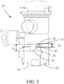
- FIG. 3 is a schematic perspective view of a pump including the motor in FIG. 1 .
- a first height H1 of the first connector 18 is greater than a second height H2 of the second connector 20.
- the flexibility of the first connector 18 can be greater than that of the second connector 20.
- the first connector 18 and the second connector 20 respectively include a first middle portion 28 and a second middle portion 30 alternating with the housing 16, and the first height H1 and the second height H2 are respectively a height of the first middle portion 28 and a height of the second middle portion 30.
- the flexibility of the first middle portion 28 of the first connector 18 can be greater than that of the second middle portion 30 of the second connector 20.
- the first middle portion 28 and the second middle portion 30 may extend along a direction parallel to the axial direction of the motor 10, and the first height H1 and the second height H2 may be a height of the first middle portion 28 and a height of the second middle portion 30 along the direction parallel to the axial direction of the motor 10.
- the first connector 18 and the second connector 20 may respectively include a first extending portion 25 ( FIG. 1 ) and a second extending portion 27 ( FIG. 1 ) radially extending outward from the housing 16, the first middle portion 28 and the second middle portion 30 extending upward from the first extending portion 25 and the second extending portion 27, and the first joint portion 24 and the second joint portion 26 radially extending inward from the first middle portion 28 and the second middle portion 30. Due to the existence of the first extending portion 25 and the second extending portion 27, the first middle portion 28 and the second middle portion 30 alternate with the housing 16.
- the first extending portion 25 may be located below the shoulder 22.
- the first joint portion 24 and the second joint portion 26 may be located above the shoulder 22.
- the second connector 20 includes a reinforcing rib 32.
- the second connector 20 has relatively high strength, thereby reducing or eliminating a possibility that the second connector 20 is damaged or broken.
- Another aspect of the embodiments of the present utility model relates to a pump 50, including the motor 10 described above.
- the first connector 18 and the second connector 20 can be configured to bond the motor 10 to another element, such as a pump case, for use.
- the first connector 18 may alleviate most, if not all, of the displacement between the motor 10 and the another element, and the second connector absorbs 20 the remaining displacement, if any, to reduce or eliminate a possibility that the motor 10 separates from the another element because the first connector 18 and the second connector 20 are broken and out of service separately, simultaneously, or totally, so that the motor 10 and the pump 50 have prolonged service lives and improved performance.
- the pump 50 may be configured to process fluids such as water (not shown in the figure).
- the motor 10 may help to provide power for the fluids such as water.
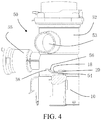
- FIG. 4 is a schematic partial cross-sectional view of the pump in FIG. 3 .
- the pump 50 includes a pump case 52, where the pump case 52 includes an engagement portion 54 bonded to the first connector 18.
- the pump case 52 and the motor 10 can be bonded to each other reliably and firmly.
- the motor 10 may help the fluids, such as water, to flow from an inlet 53 of the pump case 52 to an outlet 55.
- the engagement portion 54 is spaced apart from the second connector 20.
- the second connector 20 can be then bonded to the engagement portion 54, to absorb the remaining displacement between the motor 10 and the pump case 52.
- the pump case 52 includes a liquid such as water
- the liquid may be frozen and expand, causing the pump case 52 and the motor 10 to move toward directions of separating from each other.
- the first connector 18 may maintain sufficient elasticity while maintaining specific resistance during the movement, and after a specific distance at which no fracture may occur is moved, the second connector 20 is engaged with the pump case 52, to absorb expansion displacement of the liquid within an elastic deformation distance range of the second connector 20, so that in a solidification and expansion process of the liquid, the pump case 52 and the motor 10 maintain a reliable connection, to ensure normal working of the pump 50.
- the first connector 18 includes a limiting portion 56
- the engagement portion 54 includes a step portion 58 engaged with the limiting portion 56.
- Engagement between the limiting portion 56 and the step portion 58 may be beneficial to mutual positioning when the pump case 52 is bonded to the motor 10.
- the step portion 58 may help to prevent the limiting portion 56 from moving, for example, to the left and the bottom in FIG. 4 , to further prevent the motor 10 from moving, for example, to the left and the bottom in FIG. 4 relative to the pump case 52.
- FIG. 5 is a schematic partial enlarged cross-sectional view of the pump in FIG. 3 .
- the engagement portion 54 is located between the first connector 18 and the housing 16.
- the first connector 18 and the housing 16 can position the engagement portion 54 between the first connector and the housing.
- the engagement portion 54 may be a flange radially outward from at a lower part of the pump case 52.
- the lower part of the pump case 52 abuts between the head portion 19 and the first connector 18 and between the head portion 19 and the second connector 20, which may help to prevent the pump case 52 and the motor 10 from moving relative to each other in a left-right direction shown in FIG. 5 or in a radial direction of the housing 16.
- the engagement portion 54 extends into a space among the first connector 18, the second connector 20, and the shoulder 22, and abuts against the shoulder 22 and the first joint portion 24, which may help to prevent the pump case 52 and the motor 10 from moving relative to each other in an up-down direction shown in FIG. 5 or in an axial direction of the housing 16.
- sealing ring 53 between the head portion 19 and the pump case 52, to improve the sealing between the motor 10 and the pump case 52.
- FIG. 6 is a schematic partial cross-sectional view of a household appliance including the pump in FIG. 3 .
- another aspect of the embodiments of the present utility model relates to a household appliance 100, including the pump 50 described above.
- the first connector 18 and the second connector 20 can be configured to bond the motor 10 to another element, such as a pump case, for use.
- the first connector 18 may alleviate most, if not all, of the displacement between the motor 10 and the another element, and the second connector absorbs 20 the remaining displacement, if any, to reduce or eliminate a possibility that the motor 10 separates from the another element because the first connector 18 and the second connector 20 are broken and out of service separately, simultaneously, or totally, so that the motor 10, the pump 50, and the household appliance 100 have prolonged service lives and improved performance.
- Still another aspect of the embodiments of the present utility model relates to a household appliance 100, including the motor 10 described above.
- the first connector 18 and the second connector 20 can be configured to bond the motor 10 to another element, such as a pump case, for use.
- the first connector 18 may alleviate most, if not all, of the displacement between the motor 10 and the another element, and the second connector absorbs 20 the remaining displacement, if any, to reduce or eliminate a possibility that the motor 10 separates from the another element because the first connector 18 and the second connector 20 are broken and out of service separately, simultaneously, or totally, so that the motor 10 and the household appliance 100 have prolonged service lives and improved performance.
- the household appliance 100 is a dishwasher or a washing machine.
- the first connector 18 and the second connector 20 can be configured to bond the motor 10 to another element, such as a pump case, for use.
- the first connector 18 may alleviate most, if not all, of the displacement between the motor 10 and the another element, and the second connector absorbs 20 the remaining displacement, if any, to reduce or eliminate a possibility that the motor 10 separates from the another element because the first connector 18 and the second connector 20 are broken and out of service separately, simultaneously, or totally, so that the motor 10 and the dishwasher or the washing machine have prolonged service lives and improved performance.
- the household appliance 100 may include a cavity 102, a base 104 supporting the cavity 102, and a trough 106 installed in the cavity 102.
- the cavity 102 may receive an item (not shown in the figure) that needs to be washed.
- the pump 50 may be a fluid discharge pump of the household appliance 100, be installed in the trough 106, and discharge fluids after washing in the cavity 102 through an inlet 108 of the trough 106 to an outlet 110 of the trough 106, to discharge the fluids out of the household appliance 100.
Landscapes
- Engineering & Computer Science (AREA)
- Mechanical Engineering (AREA)
- General Engineering & Computer Science (AREA)
- Structures Of Non-Positive Displacement Pumps (AREA)
- Connection Of Motors, Electrical Generators, Mechanical Devices, And The Like (AREA)
Abstract
Description
- The present utility model relates to a motor, a pump, and a household appliance.
- Existing motors are generally used in combination with another element such as a pump case. However, in processes such as transportation, storage, and use, the motor may separate from the another element, which affects performance and a service life of the motor. Consequently, a pump or a household appliance, such as a washing machine or a dishwasher, including the motor is unsatisfactory.
- An objective of the present utility model is to provide an improved motor, pump, and household appliance.
- For the foregoing objective, an aspect of embodiments of the present utility model relates to a motor, including: a machine body; and a casing, including a housing accommodating the machine body inside, and a first connector and a second connector extending outward from the housing, where flexibility of the first connector is greater than that of the second connector.
- In this way, the first connector and the second connector can be configured to bond the motor to another element, such as a pump case, for use. In processes such as transportation, storage, and use, if the motor has a tendency to separate from the another element, the first connector may alleviate most, if not all, of the displacement between the motor and the another element, and the second connector absorbs the remaining displacement, if any, to reduce or eliminate a possibility that the motor separates from the another element because the first connector and the second connector are broken and out of service separately, simultaneously, or totally, so that the motor has a prolonged service life and improved performance.
- Optionally, the casing includes a shoulder, the first connector and the second connector respectively include a first joint portion and a second joint portion, and a first distance of the first joint portion relative to the shoulder is less than a second distance of the second joint portion relative to the shoulder.
- In this way, after the first connector may alleviate most, if not all, of the displacement between the motor and the another element, the second connector absorbs the remaining displacement, if any, to reduce or eliminate a possibility that the motor separates from the another element because the first connector and the second connector are broken and out of service separately, simultaneously, or totally, so that the motor has a prolonged service life and improved performance.
- Optionally, the first joint portion and the second joint portion are separately disposed opposite to the shoulder.
- In this way, the first joint portion and the second joint portion can be configured to bond the motor to another element, such as a pump case, for use.
- Optionally, a first height of the first connector is greater than a second height of the second connector.
- In this way, the flexibility of the first connector can be greater than that of the second connector.
- Optionally, the first connector and the second connector respectively include a first middle portion and a second middle portion alternating with the housing, and the first height and the second height are respectively a height of the first middle portion and a height of the second middle portion.
- In this way, the flexibility of the first middle portion of the first connector can be greater than that of the second middle portion of the second connector.
- Optionally, the second connector includes a reinforcing rib.
- In this way, the second connector has relatively high strength, thereby reducing or eliminating a possibility that the second connector is damaged or broken.
- Another aspect of the embodiments of the present utility model relates to a pump, including the motor described above.
- In this way, the first connector and the second connector can be configured to bond the motor to another element, such as a pump case, for use. In processes such as transportation, storage, and use, if the motor has a tendency to separate from the another element, the first connector may alleviate most, if not all, of the displacement between the motor and the another element, and the second connector absorbs the remaining displacement, if any, to reduce or eliminate a possibility that the motor separates from the another element because the first connector and the second connector are broken and out of service separately, simultaneously, or totally, so that the motor and the pump have prolonged service lives and improved performance.
- Optionally, the pump includes a pump case, where the pump case includes an engagement portion bonded to the first connector.
- In this way, the pump case and the motor can be bonded to each other reliably and firmly.
- Optionally, the engagement portion is spaced apart from the second connector.
- In this way, after the first connector is deformed to some extent, the second connector can be bonded to the engagement portion, to absorb the remaining displacement, if any, between the motor and the pump case.
- Optionally, the first connector includes a limiting portion, and the engagement portion includes a step portion engaged with the limiting portion.
- Engagement between the limiting portion and the step portion may be beneficial to mutual positioning when the pump case is bonded to the motor.
- Optionally, the engagement portion is located between the first connector and the housing.
- In this way, the first connector and the housing can position the engagement portion between the first connector and the housing.
- Still another aspect of the embodiments of the present utility model relates to a household appliance, including the pump described above.
- In this way, the first connector and the second connector can be configured to bond the motor to another element, such as a pump case, for use. In processes such as transportation, storage, and use, if the motor has a tendency to separate from the another element, the first connector may alleviate most, if not all, of the displacement between the motor and the another element, and the second connector absorbs the remaining displacement, if any, to reduce or eliminate a possibility that the motor separates from the another element because the first connector and the second connector are broken and out of service separately, simultaneously, or totally, so that the motor, the pump, and the household appliance have prolonged service lives and improved performance.
- Still another aspect of the embodiments of the present utility model relates to a household appliance, including the motor described above.
- In this way, the first connector and the second connector can be configured to bond the motor to another element, such as a pump case, for use. In processes such as transportation, storage, and use, if the motor has a tendency to separate from the another element, the first connector may alleviate most, if not all, of the displacement between the motor and the another element, and the second connector absorbs the remaining displacement, if any, to reduce or eliminate a possibility that the motor separates from the another element because the first connector and the second connector are broken and out of service separately, simultaneously, or totally, so that the motor and the household appliance are prolonged service lives and improved performance.
- Optionally, the household appliance is a dishwasher or a washing machine.
- In this way, the first connector and the second connector can be configured to bond the motor to another element, such as a pump case, for use. In processes such as transportation, storage, and use, if the motor has a tendency to separate from the another element, the first connector may alleviate most, if not all, of the displacement between the motor and the another element, and the second connector absorbs the remaining displacement, if any, to reduce or eliminate a possibility that the motor separates from the another element because the first connector and the second connector are broken and out of service separately, simultaneously, or totally, so that the motor and the dishwasher or the washing machine have prolonged service lives and improved performance.
- If technical conditions permit, the subject matter claimed by any independent claim in this application can be combined with a single subject matter or a combination of a plurality of subject matters claimed by any dependent claims to form a novel subject matter.
- The present utility model is further described below with reference to the accompanying drawings. Same or similar reference numerals are used in the figures to denote same or similar elements in different embodiments, and descriptions of the same or similar elements in different embodiments, as well as descriptions of elements, features, and effects in the related art may also be omitted.
-
-
FIG. 1 is a schematic perspective view of a motor according to an embodiment of the present utility model; -
FIG. 2 is a schematic partial enlarged view of the motor inFIG. 1 ; -
FIG. 3 is a schematic perspective view of a pump including the motor inFIG. 1 ; -
FIG. 4 is a schematic partial cross-sectional view of the pump inFIG. 3 ; -
FIG. 5 is a schematic partial enlarged cross-sectional view of the pump inFIG. 3 ; and -
FIG. 6 is a schematic partial cross-sectional view of a household appliance including the pump inFIG. 3 . -
FIG. 1 is a schematic perspective view of a motor according to an embodiment of the present utility model. As shown inFIG. 1 , an aspect of the embodiments of the present utility model relates to amotor 10, including: amachine body 12; and acasing 14, including ahousing 16 accommodating themachine body 12 inside, and afirst connector 18 and asecond connector 20 extending outward from thehousing 16, where flexibility of thefirst connector 18 is greater than that of thesecond connector 20. - In this way, the
first connector 18 and thesecond connector 20 can be configured to bond themotor 10 to another element, such as a pump case, for use. In processes such as transportation, storage, and use, if themotor 10 has a tendency to separate from the another element, thefirst connector 18 may alleviate most, if not all, of the displacement between themotor 10 and the another element, and the second connector absorbs 20 the remaining displacement, if any, to reduce or eliminate a possibility that themotor 10 separates from the another element because thefirst connector 18 and thesecond connector 20 are broken and out of service separately, simultaneously, or totally, so that themotor 10 has a prolonged service life and improved performance. - The
motor 10 may be configured to receive electric energy, output kinetic energy, and provide power by using themachine body 12. Thecasing 14 may support and protect themachine body 12. - In processes such as transportation, storage, and use, if the
motor 10 has a tendency to separate from the another element, since thefirst connector 18 has relatively large flexibility, the first connector can alleviate a relatively large displacement between themotor 10 and the another element without being broken and out of service. If the displacement between themotor 10 and the another element reaches or exceeds an upper limit of a range of thefirst connector 18 can bear, thesecond connector 20 may absorb the extra displacement, to prevent thefirst connector 18 from being broken and out of service. Even thefirst connector 18 is broken and out of service, thesecond connector 20 can still maintain the bonding between themotor 10 and the another element, so that a possibility that themotor 10 separates from the another element is reduced or eliminated, themotor 10 has a prolonged service life and improved performance. - Unless otherwise specified, "inner" and "outer" in this specification may be used relative to a center of the
motor 10. For example, when two are compared, the one close to the center of themotor 10 is an inner one, and the one far away from the center of themotor 10 is an outer one. -
FIG. 2 is a schematic partial enlarged view of the motor inFIG. 1 . Referring toFIG. 2 , optionally, thecasing 14 includes ashoulder 22, thefirst connector 18 and thesecond connector 20 respectively include afirst joint portion 24 and asecond joint portion 26, and a first distance D1 of the firstjoint portion 24 relative to theshoulder 22 is less than a second distance D2 of thesecond joint portion 26 relative to theshoulder 22. - In this way, after the
first connector 18 may alleviate most, if not all, of the displacement between themotor 10 and the another element, thesecond connector 20 absorbs the remaining displacement, if any, to reduce or eliminate a possibility that themotor 10 separates from the another element because thefirst connector 18 and thesecond connector 20 are broken and out of service separately, simultaneously, or totally, so that themotor 10 has a prolonged service life and improved performance. - The first
joint portion 24 and the secondjoint portion 26 may be bonded to the another element respectively. The firstjoint portion 24 may be bonded to the another element first, and after thefirst connector 18 is deformed, the secondjoint portion 26 is then bonded to the another element, to implement segmented bonding, thereby reducing or eliminating a fracture or failure risk. - Optionally, the first
joint portion 24 and the secondjoint portion 26 are separately disposed opposite to theshoulder 22. - In this way, the first
joint portion 24 and the secondjoint portion 26 can be configured to bond themotor 10 to another element, such as a pump case, for use. - The first
joint portion 24 and the secondjoint portion 26 may be a tail end of thefirst connector 18 and a tail end of thesecond connector 20 respectively. Thefirst connector 18 and thesecond connector 20 may be hook-shaped respectively, and the firstjoint portion 24 and the secondjoint portion 26 may respectively be hook portions extending parallel to theshoulder 22. The first distance D1 and the second distance D2 may be a distance of the firstjoint portion 24 and a distance of the secondjoint portion 26 to theshoulder 22 respectively in a direction parallel to an axial direction of themotor 10. - The
housing 16 may be substantially cylindrical and include amain body portion 17, ahead portion 19 located above themain body portion 17 and of which a size is smaller than that of themain body portion 17, and theshoulder 22 connecting themain body portion 17 and thehead portion 19. The first distance D1 and the second distance D2 may respectively be a distance between a lower surface of the firstjoint portion 24 and an upper surface of theshoulder 22 opposite thereto and a distance between the secondjoint portion 26 and the upper surface of theshoulder 22 opposite thereto. Unless otherwise explicitly indicated, "upper" and "lower" in this specification are used relative to a direction shown in the accompanying drawing. -
FIG. 3 is a schematic perspective view of a pump including the motor inFIG. 1 . As shown inFIG. 3 , optionally, a first height H1 of thefirst connector 18 is greater than a second height H2 of thesecond connector 20. - In this way, the flexibility of the
first connector 18 can be greater than that of thesecond connector 20. - Optionally, the
first connector 18 and thesecond connector 20 respectively include a firstmiddle portion 28 and a secondmiddle portion 30 alternating with thehousing 16, and the first height H1 and the second height H2 are respectively a height of the firstmiddle portion 28 and a height of the secondmiddle portion 30. - In this way, the flexibility of the first
middle portion 28 of thefirst connector 18 can be greater than that of the secondmiddle portion 30 of thesecond connector 20. - The first
middle portion 28 and the secondmiddle portion 30 may extend along a direction parallel to the axial direction of themotor 10, and the first height H1 and the second height H2 may be a height of the firstmiddle portion 28 and a height of the secondmiddle portion 30 along the direction parallel to the axial direction of themotor 10. - The
first connector 18 and thesecond connector 20 may respectively include a first extending portion 25 (FIG. 1 ) and a second extending portion 27 (FIG. 1 ) radially extending outward from thehousing 16, the firstmiddle portion 28 and the secondmiddle portion 30 extending upward from the first extendingportion 25 and the second extendingportion 27, and the firstjoint portion 24 and the secondjoint portion 26 radially extending inward from the firstmiddle portion 28 and the secondmiddle portion 30. Due to the existence of the first extendingportion 25 and the second extendingportion 27, the firstmiddle portion 28 and the secondmiddle portion 30 alternate with thehousing 16. The first extendingportion 25 may be located below theshoulder 22. The firstjoint portion 24 and the secondjoint portion 26 may be located above theshoulder 22. - Optionally, the
second connector 20 includes a reinforcingrib 32. - In this way, the
second connector 20 has relatively high strength, thereby reducing or eliminating a possibility that thesecond connector 20 is damaged or broken. - Another aspect of the embodiments of the present utility model relates to a
pump 50, including themotor 10 described above. - In this way, the
first connector 18 and thesecond connector 20 can be configured to bond themotor 10 to another element, such as a pump case, for use. In processes such as transportation, storage, and use, if themotor 10 has a tendency to separate from the another element, thefirst connector 18 may alleviate most, if not all, of the displacement between themotor 10 and the another element, and the second connector absorbs 20 the remaining displacement, if any, to reduce or eliminate a possibility that themotor 10 separates from the another element because thefirst connector 18 and thesecond connector 20 are broken and out of service separately, simultaneously, or totally, so that themotor 10 and thepump 50 have prolonged service lives and improved performance. - The
pump 50 may be configured to process fluids such as water (not shown in the figure). Themotor 10 may help to provide power for the fluids such as water. -
FIG. 4 is a schematic partial cross-sectional view of the pump inFIG. 3 . Referring toFIG. 4 , optionally, thepump 50 includes apump case 52, where thepump case 52 includes anengagement portion 54 bonded to thefirst connector 18. - In this way, the
pump case 52 and themotor 10 can be bonded to each other reliably and firmly. - The
motor 10 may help the fluids, such as water, to flow from aninlet 53 of thepump case 52 to anoutlet 55. - Optionally, the
engagement portion 54 is spaced apart from thesecond connector 20. - In this way, after the
first connector 18 first bonded to theengagement portion 54 is deformed to some extent, thesecond connector 20 can be then bonded to theengagement portion 54, to absorb the remaining displacement between themotor 10 and thepump case 52. - In some embodiments, for example, in a case that a temperature is lower than 0 degree, if the
pump case 52 includes a liquid such as water, the liquid may be frozen and expand, causing thepump case 52 and themotor 10 to move toward directions of separating from each other. Thefirst connector 18 may maintain sufficient elasticity while maintaining specific resistance during the movement, and after a specific distance at which no fracture may occur is moved, thesecond connector 20 is engaged with thepump case 52, to absorb expansion displacement of the liquid within an elastic deformation distance range of thesecond connector 20, so that in a solidification and expansion process of the liquid, thepump case 52 and themotor 10 maintain a reliable connection, to ensure normal working of thepump 50. - Optionally, the
first connector 18 includes a limitingportion 56, and theengagement portion 54 includes astep portion 58 engaged with the limitingportion 56. - Engagement between the limiting
portion 56 and thestep portion 58 may be beneficial to mutual positioning when thepump case 52 is bonded to themotor 10. Thestep portion 58 may help to prevent the limitingportion 56 from moving, for example, to the left and the bottom inFIG. 4 , to further prevent themotor 10 from moving, for example, to the left and the bottom inFIG. 4 relative to thepump case 52. -
FIG. 5 is a schematic partial enlarged cross-sectional view of the pump inFIG. 3 . As shown inFIG. 5 , optionally, theengagement portion 54 is located between thefirst connector 18 and thehousing 16. - In this way, the
first connector 18 and thehousing 16 can position theengagement portion 54 between the first connector and the housing. - The
engagement portion 54 may be a flange radially outward from at a lower part of thepump case 52. When thepump case 52 is bonded to themotor 10, the lower part of thepump case 52 abuts between thehead portion 19 and thefirst connector 18 and between thehead portion 19 and thesecond connector 20, which may help to prevent thepump case 52 and themotor 10 from moving relative to each other in a left-right direction shown inFIG. 5 or in a radial direction of thehousing 16. Theengagement portion 54 extends into a space among thefirst connector 18, thesecond connector 20, and theshoulder 22, and abuts against theshoulder 22 and the firstjoint portion 24, which may help to prevent thepump case 52 and themotor 10 from moving relative to each other in an up-down direction shown inFIG. 5 or in an axial direction of thehousing 16. - There may be a sealing
ring 53 between thehead portion 19 and thepump case 52, to improve the sealing between themotor 10 and thepump case 52. -
FIG. 6 is a schematic partial cross-sectional view of a household appliance including the pump inFIG. 3 . Referring toFIG. 6 , another aspect of the embodiments of the present utility model relates to ahousehold appliance 100, including thepump 50 described above. - In this way, the
first connector 18 and thesecond connector 20 can be configured to bond themotor 10 to another element, such as a pump case, for use. In processes such as transportation, storage, and use, if themotor 10 has a tendency to separate from the another element, thefirst connector 18 may alleviate most, if not all, of the displacement between themotor 10 and the another element, and the second connector absorbs 20 the remaining displacement, if any, to reduce or eliminate a possibility that themotor 10 separates from the another element because thefirst connector 18 and thesecond connector 20 are broken and out of service separately, simultaneously, or totally, so that themotor 10, thepump 50, and thehousehold appliance 100 have prolonged service lives and improved performance. - Still another aspect of the embodiments of the present utility model relates to a
household appliance 100, including themotor 10 described above. - In this way, the
first connector 18 and thesecond connector 20 can be configured to bond themotor 10 to another element, such as a pump case, for use. In processes such as transportation, storage, and use, if themotor 10 has a tendency to separate from the another element, thefirst connector 18 may alleviate most, if not all, of the displacement between themotor 10 and the another element, and the second connector absorbs 20 the remaining displacement, if any, to reduce or eliminate a possibility that themotor 10 separates from the another element because thefirst connector 18 and thesecond connector 20 are broken and out of service separately, simultaneously, or totally, so that themotor 10 and thehousehold appliance 100 have prolonged service lives and improved performance. - Optionally, the
household appliance 100 is a dishwasher or a washing machine. - In this way, the
first connector 18 and thesecond connector 20 can be configured to bond themotor 10 to another element, such as a pump case, for use. In processes such as transportation, storage, and use, if themotor 10 has a tendency to separate from the another element, thefirst connector 18 may alleviate most, if not all, of the displacement between themotor 10 and the another element, and the second connector absorbs 20 the remaining displacement, if any, to reduce or eliminate a possibility that themotor 10 separates from the another element because thefirst connector 18 and thesecond connector 20 are broken and out of service separately, simultaneously, or totally, so that themotor 10 and the dishwasher or the washing machine have prolonged service lives and improved performance. - Referring to
FIG. 6 , thehousehold appliance 100 may include acavity 102, abase 104 supporting thecavity 102, and atrough 106 installed in thecavity 102. Thecavity 102 may receive an item (not shown in the figure) that needs to be washed. - The
pump 50 may be a fluid discharge pump of thehousehold appliance 100, be installed in thetrough 106, and discharge fluids after washing in thecavity 102 through aninlet 108 of thetrough 106 to anoutlet 110 of thetrough 106, to discharge the fluids out of thehousehold appliance 100. - The various specific implementations described above and shown in the accompanying drawings are only used to illustrate the present utility model, but are not all of the present utility model. Any variation made by a person of ordinary skill in the art to the present utility model within the scope of the basic technical concept of the present utility model shall fall within the protection scope of the present utility model.
Claims (13)
Applications Claiming Priority (1)
| Application Number | Priority Date | Filing Date | Title |
|---|---|---|---|
| CN202021062556.0U CN212784960U (en) | 2020-06-11 | 2020-06-11 | Motors, pumps and household appliances |
Publications (2)
| Publication Number | Publication Date |
|---|---|
| EP3922856A1 true EP3922856A1 (en) | 2021-12-15 |
| EP3922856B1 EP3922856B1 (en) | 2024-04-24 |
Family
ID=75071493
Family Applications (1)
| Application Number | Title | Priority Date | Filing Date |
|---|---|---|---|
| EP21174327.3A Active EP3922856B1 (en) | 2020-06-11 | 2021-05-18 | Motor, pump and household appliance |
Country Status (3)
| Country | Link |
|---|---|
| EP (1) | EP3922856B1 (en) |
| CN (1) | CN212784960U (en) |
| PL (1) | PL3922856T3 (en) |
Citations (5)
| Publication number | Priority date | Publication date | Assignee | Title |
|---|---|---|---|---|
| KR100819921B1 (en) * | 2007-12-14 | 2008-04-08 | 주식회사 청석 | Motor pump with cap coupled by interlocking ribs |
| DE202009003756U1 (en) * | 2008-03-17 | 2009-06-25 | Coprecitec, S.L. | Drain pump that can be used in a household electrical appliance |
| US20140234141A1 (en) * | 2011-02-10 | 2014-08-21 | Hideo Hoshi | Pump configuration |
| CN205064297U (en) * | 2015-10-17 | 2016-03-02 | 中山市富迪电器有限公司 | New water-cooled drainage pump |
| US20160169232A1 (en) * | 2014-12-11 | 2016-06-16 | Johnson Electric S.A. | Pump And Cleaning Apparatus |
-
2020
- 2020-06-11 CN CN202021062556.0U patent/CN212784960U/en active Active
-
2021
- 2021-05-18 PL PL21174327.3T patent/PL3922856T3/en unknown
- 2021-05-18 EP EP21174327.3A patent/EP3922856B1/en active Active
Patent Citations (5)
| Publication number | Priority date | Publication date | Assignee | Title |
|---|---|---|---|---|
| KR100819921B1 (en) * | 2007-12-14 | 2008-04-08 | 주식회사 청석 | Motor pump with cap coupled by interlocking ribs |
| DE202009003756U1 (en) * | 2008-03-17 | 2009-06-25 | Coprecitec, S.L. | Drain pump that can be used in a household electrical appliance |
| US20140234141A1 (en) * | 2011-02-10 | 2014-08-21 | Hideo Hoshi | Pump configuration |
| US20160169232A1 (en) * | 2014-12-11 | 2016-06-16 | Johnson Electric S.A. | Pump And Cleaning Apparatus |
| CN205064297U (en) * | 2015-10-17 | 2016-03-02 | 中山市富迪电器有限公司 | New water-cooled drainage pump |
Also Published As
| Publication number | Publication date |
|---|---|
| CN212784960U (en) | 2021-03-23 |
| PL3922856T3 (en) | 2024-07-22 |
| EP3922856B1 (en) | 2024-04-24 |
Similar Documents
| Publication | Publication Date | Title |
|---|---|---|
| EP3922856B1 (en) | Motor, pump and household appliance | |
| CN208448253U (en) | A kind of Single Degree of Freedom Magnetic suspension centrifugal impeller for reducing thrombus and occurring | |
| CN203867917U (en) | Motor for circulating pump of dish-washing machine and circulating pump of dish-washing machine | |
| KR101345228B1 (en) | United pump for heater | |
| CN103423167B (en) | A kind of positive displacement pump and assembly method thereof | |
| CN217999967U (en) | Heating pump and contain its domestic appliance | |
| CN210183109U (en) | Compressor and air conditioner | |
| CN204572400U (en) | Pump head component and there is its micro pump | |
| CN208749672U (en) | Pump | |
| CN212928296U (en) | Multistage sealing ring structure of canned motor pump | |
| CN221033143U (en) | Worm type water pump | |
| CN215521287U (en) | Multi-stage pump with novel structure | |
| CN205420827U (en) | Rotary drum washing machine's barrel head | |
| CN212055057U (en) | Air pump assembly and cleaning machine | |
| US3825373A (en) | Dishwasher assembly | |
| CN212690463U (en) | Integrated into one piece's high strength water pump shell | |
| CN209621706U (en) | Impeller seals mechanism and centrifugal pump | |
| CN211525089U (en) | Resistance to compression type vertical centrifugal pump | |
| CN215333425U (en) | Water ring vacuum pump | |
| EP4534841A1 (en) | Compressor and sealing member | |
| CN216842355U (en) | Impeller assembly for water pump | |
| CN109222824B (en) | A dishwasher | |
| JP6776150B2 (en) | underwater pump | |
| CN203430845U (en) | Core-pulling type vertical diagonal flow pump | |
| CN215820844U (en) | Heating device and pump with same |
Legal Events
| Date | Code | Title | Description |
|---|---|---|---|
| PUAI | Public reference made under article 153(3) epc to a published international application that has entered the european phase |
Free format text: ORIGINAL CODE: 0009012 |
|
| STAA | Information on the status of an ep patent application or granted ep patent |
Free format text: STATUS: THE APPLICATION HAS BEEN PUBLISHED |
|
| AK | Designated contracting states |
Kind code of ref document: A1 Designated state(s): AL AT BE BG CH CY CZ DE DK EE ES FI FR GB GR HR HU IE IS IT LI LT LU LV MC MK MT NL NO PL PT RO RS SE SI SK SM TR |
|
| B565 | Issuance of search results under rule 164(2) epc |
Effective date: 20211104 |
|
| STAA | Information on the status of an ep patent application or granted ep patent |
Free format text: STATUS: REQUEST FOR EXAMINATION WAS MADE |
|
| 17P | Request for examination filed |
Effective date: 20220615 |
|
| RBV | Designated contracting states (corrected) |
Designated state(s): AL AT BE BG CH CY CZ DE DK EE ES FI FR GB GR HR HU IE IS IT LI LT LU LV MC MK MT NL NO PL PT RO RS SE SI SK SM TR |
|
| GRAP | Despatch of communication of intention to grant a patent |
Free format text: ORIGINAL CODE: EPIDOSNIGR1 |
|
| STAA | Information on the status of an ep patent application or granted ep patent |
Free format text: STATUS: GRANT OF PATENT IS INTENDED |
|
| INTG | Intention to grant announced |
Effective date: 20231215 |
|
| GRAS | Grant fee paid |
Free format text: ORIGINAL CODE: EPIDOSNIGR3 |
|
| GRAA | (expected) grant |
Free format text: ORIGINAL CODE: 0009210 |
|
| STAA | Information on the status of an ep patent application or granted ep patent |
Free format text: STATUS: THE PATENT HAS BEEN GRANTED |
|
| AK | Designated contracting states |
Kind code of ref document: B1 Designated state(s): AL AT BE BG CH CY CZ DE DK EE ES FI FR GB GR HR HU IE IS IT LI LT LU LV MC MK MT NL NO PL PT RO RS SE SI SK SM TR |
|
| REG | Reference to a national code |
Ref country code: GB Ref legal event code: FG4D |
|
| REG | Reference to a national code |
Ref country code: CH Ref legal event code: EP |
|
| REG | Reference to a national code |
Ref country code: DE Ref legal event code: R096 Ref document number: 602021012134 Country of ref document: DE |
|
| REG | Reference to a national code |
Ref country code: IE Ref legal event code: FG4D |
|
| REG | Reference to a national code |
Ref country code: LT Ref legal event code: MG9D |
|
| REG | Reference to a national code |
Ref country code: NL Ref legal event code: MP Effective date: 20240424 |
|
| REG | Reference to a national code |
Ref country code: AT Ref legal event code: MK05 Ref document number: 1679878 Country of ref document: AT Kind code of ref document: T Effective date: 20240424 |
|
| PG25 | Lapsed in a contracting state [announced via postgrant information from national office to epo] |
Ref country code: NL Free format text: LAPSE BECAUSE OF FAILURE TO SUBMIT A TRANSLATION OF THE DESCRIPTION OR TO PAY THE FEE WITHIN THE PRESCRIBED TIME-LIMIT Effective date: 20240424 |
|
| PG25 | Lapsed in a contracting state [announced via postgrant information from national office to epo] |
Ref country code: NL Free format text: LAPSE BECAUSE OF FAILURE TO SUBMIT A TRANSLATION OF THE DESCRIPTION OR TO PAY THE FEE WITHIN THE PRESCRIBED TIME-LIMIT Effective date: 20240424 |
|
| PG25 | Lapsed in a contracting state [announced via postgrant information from national office to epo] |
Ref country code: IS Free format text: LAPSE BECAUSE OF FAILURE TO SUBMIT A TRANSLATION OF THE DESCRIPTION OR TO PAY THE FEE WITHIN THE PRESCRIBED TIME-LIMIT Effective date: 20240824 |
|
| PG25 | Lapsed in a contracting state [announced via postgrant information from national office to epo] |
Ref country code: BG Free format text: LAPSE BECAUSE OF FAILURE TO SUBMIT A TRANSLATION OF THE DESCRIPTION OR TO PAY THE FEE WITHIN THE PRESCRIBED TIME-LIMIT Effective date: 20240424 |
|
| PG25 | Lapsed in a contracting state [announced via postgrant information from national office to epo] |
Ref country code: HR Free format text: LAPSE BECAUSE OF FAILURE TO SUBMIT A TRANSLATION OF THE DESCRIPTION OR TO PAY THE FEE WITHIN THE PRESCRIBED TIME-LIMIT Effective date: 20240424 Ref country code: FI Free format text: LAPSE BECAUSE OF FAILURE TO SUBMIT A TRANSLATION OF THE DESCRIPTION OR TO PAY THE FEE WITHIN THE PRESCRIBED TIME-LIMIT Effective date: 20240424 |
|
| PG25 | Lapsed in a contracting state [announced via postgrant information from national office to epo] |
Ref country code: GR Free format text: LAPSE BECAUSE OF FAILURE TO SUBMIT A TRANSLATION OF THE DESCRIPTION OR TO PAY THE FEE WITHIN THE PRESCRIBED TIME-LIMIT Effective date: 20240725 |
|
| PG25 | Lapsed in a contracting state [announced via postgrant information from national office to epo] |
Ref country code: PT Free format text: LAPSE BECAUSE OF FAILURE TO SUBMIT A TRANSLATION OF THE DESCRIPTION OR TO PAY THE FEE WITHIN THE PRESCRIBED TIME-LIMIT Effective date: 20240826 |
|
| PG25 | Lapsed in a contracting state [announced via postgrant information from national office to epo] |
Ref country code: ES Free format text: LAPSE BECAUSE OF FAILURE TO SUBMIT A TRANSLATION OF THE DESCRIPTION OR TO PAY THE FEE WITHIN THE PRESCRIBED TIME-LIMIT Effective date: 20240424 |
|
| PG25 | Lapsed in a contracting state [announced via postgrant information from national office to epo] |
Ref country code: AT Free format text: LAPSE BECAUSE OF FAILURE TO SUBMIT A TRANSLATION OF THE DESCRIPTION OR TO PAY THE FEE WITHIN THE PRESCRIBED TIME-LIMIT Effective date: 20240424 |
|
| PG25 | Lapsed in a contracting state [announced via postgrant information from national office to epo] |
Ref country code: LV Free format text: LAPSE BECAUSE OF FAILURE TO SUBMIT A TRANSLATION OF THE DESCRIPTION OR TO PAY THE FEE WITHIN THE PRESCRIBED TIME-LIMIT Effective date: 20240424 |
|
| PG25 | Lapsed in a contracting state [announced via postgrant information from national office to epo] |
Ref country code: PT Free format text: LAPSE BECAUSE OF FAILURE TO SUBMIT A TRANSLATION OF THE DESCRIPTION OR TO PAY THE FEE WITHIN THE PRESCRIBED TIME-LIMIT Effective date: 20240826 Ref country code: NO Free format text: LAPSE BECAUSE OF FAILURE TO SUBMIT A TRANSLATION OF THE DESCRIPTION OR TO PAY THE FEE WITHIN THE PRESCRIBED TIME-LIMIT Effective date: 20240724 Ref country code: LV Free format text: LAPSE BECAUSE OF FAILURE TO SUBMIT A TRANSLATION OF THE DESCRIPTION OR TO PAY THE FEE WITHIN THE PRESCRIBED TIME-LIMIT Effective date: 20240424 Ref country code: IS Free format text: LAPSE BECAUSE OF FAILURE TO SUBMIT A TRANSLATION OF THE DESCRIPTION OR TO PAY THE FEE WITHIN THE PRESCRIBED TIME-LIMIT Effective date: 20240824 Ref country code: HR Free format text: LAPSE BECAUSE OF FAILURE TO SUBMIT A TRANSLATION OF THE DESCRIPTION OR TO PAY THE FEE WITHIN THE PRESCRIBED TIME-LIMIT Effective date: 20240424 Ref country code: GR Free format text: LAPSE BECAUSE OF FAILURE TO SUBMIT A TRANSLATION OF THE DESCRIPTION OR TO PAY THE FEE WITHIN THE PRESCRIBED TIME-LIMIT Effective date: 20240725 Ref country code: FI Free format text: LAPSE BECAUSE OF FAILURE TO SUBMIT A TRANSLATION OF THE DESCRIPTION OR TO PAY THE FEE WITHIN THE PRESCRIBED TIME-LIMIT Effective date: 20240424 Ref country code: ES Free format text: LAPSE BECAUSE OF FAILURE TO SUBMIT A TRANSLATION OF THE DESCRIPTION OR TO PAY THE FEE WITHIN THE PRESCRIBED TIME-LIMIT Effective date: 20240424 Ref country code: BG Free format text: LAPSE BECAUSE OF FAILURE TO SUBMIT A TRANSLATION OF THE DESCRIPTION OR TO PAY THE FEE WITHIN THE PRESCRIBED TIME-LIMIT Effective date: 20240424 Ref country code: AT Free format text: LAPSE BECAUSE OF FAILURE TO SUBMIT A TRANSLATION OF THE DESCRIPTION OR TO PAY THE FEE WITHIN THE PRESCRIBED TIME-LIMIT Effective date: 20240424 Ref country code: RS Free format text: LAPSE BECAUSE OF FAILURE TO SUBMIT A TRANSLATION OF THE DESCRIPTION OR TO PAY THE FEE WITHIN THE PRESCRIBED TIME-LIMIT Effective date: 20240724 |
|
| REG | Reference to a national code |
Ref country code: CH Ref legal event code: PL |
|
| PG25 | Lapsed in a contracting state [announced via postgrant information from national office to epo] |
Ref country code: DK Free format text: LAPSE BECAUSE OF FAILURE TO SUBMIT A TRANSLATION OF THE DESCRIPTION OR TO PAY THE FEE WITHIN THE PRESCRIBED TIME-LIMIT Effective date: 20240424 |
|
| PG25 | Lapsed in a contracting state [announced via postgrant information from national office to epo] |
Ref country code: LU Free format text: LAPSE BECAUSE OF NON-PAYMENT OF DUE FEES Effective date: 20240518 |
|
| PG25 | Lapsed in a contracting state [announced via postgrant information from national office to epo] |
Ref country code: EE Free format text: LAPSE BECAUSE OF FAILURE TO SUBMIT A TRANSLATION OF THE DESCRIPTION OR TO PAY THE FEE WITHIN THE PRESCRIBED TIME-LIMIT Effective date: 20240424 |
|
| PG25 | Lapsed in a contracting state [announced via postgrant information from national office to epo] |
Ref country code: CZ Free format text: LAPSE BECAUSE OF FAILURE TO SUBMIT A TRANSLATION OF THE DESCRIPTION OR TO PAY THE FEE WITHIN THE PRESCRIBED TIME-LIMIT Effective date: 20240424 |
|
| PG25 | Lapsed in a contracting state [announced via postgrant information from national office to epo] |
Ref country code: SK Free format text: LAPSE BECAUSE OF FAILURE TO SUBMIT A TRANSLATION OF THE DESCRIPTION OR TO PAY THE FEE WITHIN THE PRESCRIBED TIME-LIMIT Effective date: 20240424 Ref country code: RO Free format text: LAPSE BECAUSE OF FAILURE TO SUBMIT A TRANSLATION OF THE DESCRIPTION OR TO PAY THE FEE WITHIN THE PRESCRIBED TIME-LIMIT Effective date: 20240424 |
|
| REG | Reference to a national code |
Ref country code: DE Ref legal event code: R097 Ref document number: 602021012134 Country of ref document: DE |
|
| PG25 | Lapsed in a contracting state [announced via postgrant information from national office to epo] |
Ref country code: SM Free format text: LAPSE BECAUSE OF FAILURE TO SUBMIT A TRANSLATION OF THE DESCRIPTION OR TO PAY THE FEE WITHIN THE PRESCRIBED TIME-LIMIT Effective date: 20240424 |
|
| PG25 | Lapsed in a contracting state [announced via postgrant information from national office to epo] |
Ref country code: SM Free format text: LAPSE BECAUSE OF FAILURE TO SUBMIT A TRANSLATION OF THE DESCRIPTION OR TO PAY THE FEE WITHIN THE PRESCRIBED TIME-LIMIT Effective date: 20240424 Ref country code: SK Free format text: LAPSE BECAUSE OF FAILURE TO SUBMIT A TRANSLATION OF THE DESCRIPTION OR TO PAY THE FEE WITHIN THE PRESCRIBED TIME-LIMIT Effective date: 20240424 Ref country code: RO Free format text: LAPSE BECAUSE OF FAILURE TO SUBMIT A TRANSLATION OF THE DESCRIPTION OR TO PAY THE FEE WITHIN THE PRESCRIBED TIME-LIMIT Effective date: 20240424 Ref country code: LU Free format text: LAPSE BECAUSE OF NON-PAYMENT OF DUE FEES Effective date: 20240518 Ref country code: EE Free format text: LAPSE BECAUSE OF FAILURE TO SUBMIT A TRANSLATION OF THE DESCRIPTION OR TO PAY THE FEE WITHIN THE PRESCRIBED TIME-LIMIT Effective date: 20240424 Ref country code: DK Free format text: LAPSE BECAUSE OF FAILURE TO SUBMIT A TRANSLATION OF THE DESCRIPTION OR TO PAY THE FEE WITHIN THE PRESCRIBED TIME-LIMIT Effective date: 20240424 Ref country code: CZ Free format text: LAPSE BECAUSE OF FAILURE TO SUBMIT A TRANSLATION OF THE DESCRIPTION OR TO PAY THE FEE WITHIN THE PRESCRIBED TIME-LIMIT Effective date: 20240424 Ref country code: CH Free format text: LAPSE BECAUSE OF NON-PAYMENT OF DUE FEES Effective date: 20240531 Ref country code: MC Free format text: LAPSE BECAUSE OF FAILURE TO SUBMIT A TRANSLATION OF THE DESCRIPTION OR TO PAY THE FEE WITHIN THE PRESCRIBED TIME-LIMIT Effective date: 20240424 |
|
| REG | Reference to a national code |
Ref country code: BE Ref legal event code: MM Effective date: 20240531 |
|
| PLBE | No opposition filed within time limit |
Free format text: ORIGINAL CODE: 0009261 |
|
| STAA | Information on the status of an ep patent application or granted ep patent |
Free format text: STATUS: NO OPPOSITION FILED WITHIN TIME LIMIT |
|
| 26N | No opposition filed |
Effective date: 20250127 |
|
| PG25 | Lapsed in a contracting state [announced via postgrant information from national office to epo] |
Ref country code: IE Free format text: LAPSE BECAUSE OF NON-PAYMENT OF DUE FEES Effective date: 20240518 |
|
| PG25 | Lapsed in a contracting state [announced via postgrant information from national office to epo] |
Ref country code: SI Free format text: LAPSE BECAUSE OF FAILURE TO SUBMIT A TRANSLATION OF THE DESCRIPTION OR TO PAY THE FEE WITHIN THE PRESCRIBED TIME-LIMIT Effective date: 20240424 Ref country code: BE Free format text: LAPSE BECAUSE OF NON-PAYMENT OF DUE FEES Effective date: 20240531 |
|
| PGFP | Annual fee paid to national office [announced via postgrant information from national office to epo] |
Ref country code: DE Payment date: 20250531 Year of fee payment: 5 Ref country code: PL Payment date: 20250430 Year of fee payment: 5 |
|
| PGFP | Annual fee paid to national office [announced via postgrant information from national office to epo] |
Ref country code: GB Payment date: 20250522 Year of fee payment: 5 |
|
| PGFP | Annual fee paid to national office [announced via postgrant information from national office to epo] |
Ref country code: FR Payment date: 20250523 Year of fee payment: 5 |
|
| PG25 | Lapsed in a contracting state [announced via postgrant information from national office to epo] |
Ref country code: CY Free format text: LAPSE BECAUSE OF FAILURE TO SUBMIT A TRANSLATION OF THE DESCRIPTION OR TO PAY THE FEE WITHIN THE PRESCRIBED TIME-LIMIT; INVALID AB INITIO Effective date: 20210518 |
|
| PG25 | Lapsed in a contracting state [announced via postgrant information from national office to epo] |
Ref country code: HU Free format text: LAPSE BECAUSE OF FAILURE TO SUBMIT A TRANSLATION OF THE DESCRIPTION OR TO PAY THE FEE WITHIN THE PRESCRIBED TIME-LIMIT; INVALID AB INITIO Effective date: 20210518 |
|
| PG25 | Lapsed in a contracting state [announced via postgrant information from national office to epo] |
Ref country code: SE Free format text: LAPSE BECAUSE OF FAILURE TO SUBMIT A TRANSLATION OF THE DESCRIPTION OR TO PAY THE FEE WITHIN THE PRESCRIBED TIME-LIMIT Effective date: 20240424 |
|
| PG25 | Lapsed in a contracting state [announced via postgrant information from national office to epo] |
Ref country code: IT Free format text: LAPSE BECAUSE OF NON-PAYMENT OF DUE FEES Effective date: 20240518 |
|
| PG25 | Lapsed in a contracting state [announced via postgrant information from national office to epo] |
Ref country code: IT Free format text: LAPSE BECAUSE OF NON-PAYMENT OF DUE FEES Effective date: 20240518 |
|
| PGFP | Annual fee paid to national office [announced via postgrant information from national office to epo] |
Ref country code: IT Payment date: 20250530 Year of fee payment: 5 |
|
| PGRI | Patent reinstated in contracting state [announced from national office to epo] |
Ref country code: IT Effective date: 20240531 |