EP3922781A1 - A panel system with an installation profile having one or more border sections, and a method of adapting such a panel system - Google Patents
A panel system with an installation profile having one or more border sections, and a method of adapting such a panel system Download PDFInfo
- Publication number
- EP3922781A1 EP3922781A1 EP21179122.3A EP21179122A EP3922781A1 EP 3922781 A1 EP3922781 A1 EP 3922781A1 EP 21179122 A EP21179122 A EP 21179122A EP 3922781 A1 EP3922781 A1 EP 3922781A1
- Authority
- EP
- European Patent Office
- Prior art keywords
- panel
- profile
- hinge
- panel system
- flange
- Prior art date
- Legal status (The legal status is an assumption and is not a legal conclusion. Google has not performed a legal analysis and makes no representation as to the accuracy of the status listed.)
- Granted
Links
Images







Classifications
-
- E—FIXED CONSTRUCTIONS
- E04—BUILDING
- E04B—GENERAL BUILDING CONSTRUCTIONS; WALLS, e.g. PARTITIONS; ROOFS; FLOORS; CEILINGS; INSULATION OR OTHER PROTECTION OF BUILDINGS
- E04B7/00—Roofs; Roof construction with regard to insulation
- E04B7/02—Roofs; Roof construction with regard to insulation with plane sloping surfaces, e.g. saddle roofs
-
- E—FIXED CONSTRUCTIONS
- E04—BUILDING
- E04B—GENERAL BUILDING CONSTRUCTIONS; WALLS, e.g. PARTITIONS; ROOFS; FLOORS; CEILINGS; INSULATION OR OTHER PROTECTION OF BUILDINGS
- E04B7/00—Roofs; Roof construction with regard to insulation
- E04B7/16—Roof structures with movable roof parts
- E04B7/163—Roof structures with movable roof parts characterised by a pivoting movement of the movable roof parts
-
- E—FIXED CONSTRUCTIONS
- E04—BUILDING
- E04D—ROOF COVERINGS; SKY-LIGHTS; GUTTERS; ROOF-WORKING TOOLS
- E04D3/00—Roof covering by making use of flat or curved slabs or stiff sheets
- E04D3/36—Connecting; Fastening
- E04D3/366—Connecting; Fastening by closing the space between the slabs or sheets by gutters, bulges, or bridging elements, e.g. strips
-
- E—FIXED CONSTRUCTIONS
- E04—BUILDING
- E04B—GENERAL BUILDING CONSTRUCTIONS; WALLS, e.g. PARTITIONS; ROOFS; FLOORS; CEILINGS; INSULATION OR OTHER PROTECTION OF BUILDINGS
- E04B7/00—Roofs; Roof construction with regard to insulation
- E04B7/02—Roofs; Roof construction with regard to insulation with plane sloping surfaces, e.g. saddle roofs
- E04B7/06—Constructions of roof intersections or hipped ends
-
- E—FIXED CONSTRUCTIONS
- E04—BUILDING
- E04B—GENERAL BUILDING CONSTRUCTIONS; WALLS, e.g. PARTITIONS; ROOFS; FLOORS; CEILINGS; INSULATION OR OTHER PROTECTION OF BUILDINGS
- E04B7/00—Roofs; Roof construction with regard to insulation
- E04B7/20—Roofs consisting of self-supporting slabs, e.g. able to be loaded
-
- E—FIXED CONSTRUCTIONS
- E04—BUILDING
- E04B—GENERAL BUILDING CONSTRUCTIONS; WALLS, e.g. PARTITIONS; ROOFS; FLOORS; CEILINGS; INSULATION OR OTHER PROTECTION OF BUILDINGS
- E04B7/00—Roofs; Roof construction with regard to insulation
- E04B7/20—Roofs consisting of self-supporting slabs, e.g. able to be loaded
- E04B7/22—Roofs consisting of self-supporting slabs, e.g. able to be loaded the slabs having insulating properties, e.g. laminated with layers of insulating material
-
- E—FIXED CONSTRUCTIONS
- E04—BUILDING
- E04D—ROOF COVERINGS; SKY-LIGHTS; GUTTERS; ROOF-WORKING TOOLS
- E04D13/00—Special arrangements or devices in connection with roof coverings; Protection against birds; Roof drainage ; Sky-lights
- E04D13/03—Sky-lights; Domes; Ventilating sky-lights
-
- E—FIXED CONSTRUCTIONS
- E04—BUILDING
- E04D—ROOF COVERINGS; SKY-LIGHTS; GUTTERS; ROOF-WORKING TOOLS
- E04D13/00—Special arrangements or devices in connection with roof coverings; Protection against birds; Roof drainage ; Sky-lights
- E04D13/03—Sky-lights; Domes; Ventilating sky-lights
- E04D13/032—Supports or connecting means for sky-lights of vaulted shape
-
- E—FIXED CONSTRUCTIONS
- E04—BUILDING
- E04D—ROOF COVERINGS; SKY-LIGHTS; GUTTERS; ROOF-WORKING TOOLS
- E04D13/00—Special arrangements or devices in connection with roof coverings; Protection against birds; Roof drainage ; Sky-lights
- E04D13/03—Sky-lights; Domes; Ventilating sky-lights
- E04D13/033—Sky-lights; Domes; Ventilating sky-lights provided with means for controlling the light-transmission or the heat-reflection, (e.g. shields, reflectors, cleaning devices)
-
- E—FIXED CONSTRUCTIONS
- E04—BUILDING
- E04D—ROOF COVERINGS; SKY-LIGHTS; GUTTERS; ROOF-WORKING TOOLS
- E04D13/00—Special arrangements or devices in connection with roof coverings; Protection against birds; Roof drainage ; Sky-lights
- E04D13/03—Sky-lights; Domes; Ventilating sky-lights
- E04D13/035—Sky-lights; Domes; Ventilating sky-lights characterised by having movable parts
- E04D13/0351—Sky-lights; Domes; Ventilating sky-lights characterised by having movable parts the parts pivoting about a fixed axis
- E04D13/0354—Sky-lights; Domes; Ventilating sky-lights characterised by having movable parts the parts pivoting about a fixed axis the parts being flat
-
- E—FIXED CONSTRUCTIONS
- E04—BUILDING
- E04D—ROOF COVERINGS; SKY-LIGHTS; GUTTERS; ROOF-WORKING TOOLS
- E04D3/00—Roof covering by making use of flat or curved slabs or stiff sheets
-
- E—FIXED CONSTRUCTIONS
- E04—BUILDING
- E04D—ROOF COVERINGS; SKY-LIGHTS; GUTTERS; ROOF-WORKING TOOLS
- E04D3/00—Roof covering by making use of flat or curved slabs or stiff sheets
- E04D3/02—Roof covering by making use of flat or curved slabs or stiff sheets of plane slabs, slates, or sheets, or in which the cross-section is unimportant
- E04D3/06—Roof covering by making use of flat or curved slabs or stiff sheets of plane slabs, slates, or sheets, or in which the cross-section is unimportant of glass or other translucent material; Fixing means therefor
-
- E—FIXED CONSTRUCTIONS
- E04—BUILDING
- E04D—ROOF COVERINGS; SKY-LIGHTS; GUTTERS; ROOF-WORKING TOOLS
- E04D3/00—Roof covering by making use of flat or curved slabs or stiff sheets
- E04D3/02—Roof covering by making use of flat or curved slabs or stiff sheets of plane slabs, slates, or sheets, or in which the cross-section is unimportant
- E04D3/06—Roof covering by making use of flat or curved slabs or stiff sheets of plane slabs, slates, or sheets, or in which the cross-section is unimportant of glass or other translucent material; Fixing means therefor
- E04D3/08—Roof covering by making use of flat or curved slabs or stiff sheets of plane slabs, slates, or sheets, or in which the cross-section is unimportant of glass or other translucent material; Fixing means therefor with metal glazing bars
-
- E—FIXED CONSTRUCTIONS
- E04—BUILDING
- E04D—ROOF COVERINGS; SKY-LIGHTS; GUTTERS; ROOF-WORKING TOOLS
- E04D3/00—Roof covering by making use of flat or curved slabs or stiff sheets
- E04D3/36—Connecting; Fastening
-
- E—FIXED CONSTRUCTIONS
- E04—BUILDING
- E04D—ROOF COVERINGS; SKY-LIGHTS; GUTTERS; ROOF-WORKING TOOLS
- E04D3/00—Roof covering by making use of flat or curved slabs or stiff sheets
- E04D3/36—Connecting; Fastening
- E04D3/3607—Connecting; Fastening the fastening means comprising spacer means adapted to the shape of the profiled roof covering
-
- H—ELECTRICITY
- H02—GENERATION; CONVERSION OR DISTRIBUTION OF ELECTRIC POWER
- H02S—GENERATION OF ELECTRIC POWER BY CONVERSION OF INFRARED RADIATION, VISIBLE LIGHT OR ULTRAVIOLET LIGHT, e.g. USING PHOTOVOLTAIC [PV] MODULES
- H02S20/00—Supporting structures for PV modules
- H02S20/20—Supporting structures directly fixed to an immovable object
- H02S20/22—Supporting structures directly fixed to an immovable object specially adapted for buildings
- H02S20/26—Building materials integrated with PV modules, e.g. façade elements
-
- E—FIXED CONSTRUCTIONS
- E04—BUILDING
- E04D—ROOF COVERINGS; SKY-LIGHTS; GUTTERS; ROOF-WORKING TOOLS
- E04D3/00—Roof covering by making use of flat or curved slabs or stiff sheets
- E04D3/02—Roof covering by making use of flat or curved slabs or stiff sheets of plane slabs, slates, or sheets, or in which the cross-section is unimportant
- E04D3/06—Roof covering by making use of flat or curved slabs or stiff sheets of plane slabs, slates, or sheets, or in which the cross-section is unimportant of glass or other translucent material; Fixing means therefor
- E04D3/08—Roof covering by making use of flat or curved slabs or stiff sheets of plane slabs, slates, or sheets, or in which the cross-section is unimportant of glass or other translucent material; Fixing means therefor with metal glazing bars
- E04D2003/0868—Mutual connections and details of glazing bars
- E04D2003/0875—Mutual connections and details of glazing bars on the ridge of the roof or on intersecting roof parts
-
- Y—GENERAL TAGGING OF NEW TECHNOLOGICAL DEVELOPMENTS; GENERAL TAGGING OF CROSS-SECTIONAL TECHNOLOGIES SPANNING OVER SEVERAL SECTIONS OF THE IPC; TECHNICAL SUBJECTS COVERED BY FORMER USPC CROSS-REFERENCE ART COLLECTIONS [XRACs] AND DIGESTS
- Y02—TECHNOLOGIES OR APPLICATIONS FOR MITIGATION OR ADAPTATION AGAINST CLIMATE CHANGE
- Y02B—CLIMATE CHANGE MITIGATION TECHNOLOGIES RELATED TO BUILDINGS, e.g. HOUSING, HOUSE APPLIANCES OR RELATED END-USER APPLICATIONS
- Y02B10/00—Integration of renewable energy sources in buildings
- Y02B10/10—Photovoltaic [PV]
-
- Y—GENERAL TAGGING OF NEW TECHNOLOGICAL DEVELOPMENTS; GENERAL TAGGING OF CROSS-SECTIONAL TECHNOLOGIES SPANNING OVER SEVERAL SECTIONS OF THE IPC; TECHNICAL SUBJECTS COVERED BY FORMER USPC CROSS-REFERENCE ART COLLECTIONS [XRACs] AND DIGESTS
- Y02—TECHNOLOGIES OR APPLICATIONS FOR MITIGATION OR ADAPTATION AGAINST CLIMATE CHANGE
- Y02E—REDUCTION OF GREENHOUSE GAS [GHG] EMISSIONS, RELATED TO ENERGY GENERATION, TRANSMISSION OR DISTRIBUTION
- Y02E10/00—Energy generation through renewable energy sources
- Y02E10/50—Photovoltaic [PV] energy
Definitions
- the present invention relates to a panel system comprising a number of fixed panels and a number of openable panels, each fixed panel and each openable panel comprising a frame structure composed of a set of profile elements encasing a panelling element, said frame structure including one top profile element configured to be connected to a supporting structure by means of a mounting and hinge assembly of said panel system.
- the invention furthermore relates to a method of adapting such a panel system.
- Panel fillets comprising fixed or openable panels arranged in pitched or flat roofs may be provided in a number of varieties and often include complicated structures in order to allow opening of the sash and to fulfil other functions, such as ventilation, waterproofing and thermal insulation, while permitting cleaning of the outside of the pane from inside the building.
- the varieties include roof windows of the pivoting type, the hinge axis being either located at the centre or displaced from the centre of the window, and top-hung roof windows that pivot for cleaning by means of an intermediate frame. Furthermore, water and other precipitation may enter into the window structure and penetrate under the panel system. Heat losses may also occur between the different components of the panel system structure.
- a panel system of the kind mentioned in the introduction which is furthermore characterised in that the mounting and hinge assembly comprises an installation profile with a main body having a first, interior end and a second, exterior end, and that at least one border section is provided in connection with at least one of the first, interior end and the second, exterior end of the main body.
- the installation profile is easy to connect to a supporting structure. Dividing the installation profile into the main body and the border section or border sections entails that a uniform main body may be utilised in a number of various installation profiles, whereas each border section may be tailored to the specific field of application of the panel system.
- the border section or border section may be formed integral with the main body but may also constitute a separate part.
- the material of the installation profile may in principle be chosen in accordance with the specific requirements.
- the installation profile comprises an extruded profile of a metallic material.
- At least one of the border sections of the installation profile is exchangeable for an extension element of a thermal insulation material. This makes it possible to adapt the installation profile to the intended installation configuration and environment. Thus, in panel systems intended to be installed in a warm climate, the entire installation profile may remain intact, whereas in panel systems to be installed in colder climates, the border section or border sections may be exchanged to improve the overall thermal insulating properties of the panel system.
- the installation profile is provided with a top leg at the second, exterior end of the main body, the top leg extending away from the top profile element of each fixed panel and each openable panel, and wherein the top leg includes engagement means for engagement with a top extension element.
- the top extension element comprises two snap fit legs for engagement with the top leg of the installation profile and a top extension element recess. Snap connections, whether providing a positive, form-fitting engagement or a non-positive, force-fitting engagement, are easily handled and reliable.
- a method of adapting such a panel system comprises the steps of:
- FIG. 1 embodiments of a panel system 3 will be described in further detail.
- the panel system 3 can for instance be designed to form part of a panel fillet or another major panel surface which in the shown embodiment constitutes at least one part of a glass roof.
- the panel system 3 comprises a number of fixed panels 1 and one or more openable panels 2.
- Each fixed panel 1 and each openable panel 2 comprises usually an orthogonal, or square, frame structure forming an essentially rectangular frame structure composed of a set of profile elements.
- four profile elements are provided, namely a top profile element 11, two side profile elements 12, 13 and a bottom profile element 14 of the fixed panel 1 and correspondingly a top profile element 21, two side profile elements 22 and a bottom profile element 24 for the openable panel 2.
- the openable panel 2 is at its top element 21 hingedly connected to a supporting structure in a manner to be described in further detail below.
- the panel system 3 may, at most, comprise as many openable panels 2 as fixed panels 1 or may comprise fewer openable panels 2 than fixed panels 1. It is also possible to configure the panel systems 3 with only fixed panels 1.
- Each fixed panel 1 and each openable panel 2 comprises a panelling element 5.
- the panelling element 5 comprises an insulating glazing unit, or IGU.
- the panelling element 5 may comprise or be replaced by any of a photovoltaic element e.g. solar cells, a blinded element, an IGU with built-in shading e.g. venetian blind, a panelling element filled with aerogel and/or a combination of these.
- a photovoltaic element e.g. solar cells
- a blinded element e.g. an IGU with built-in shading e.g. venetian blind
- a panelling element filled with aerogel e.g. venetian blind
- the panels 1, 2 of the panel system 3 can be used for many other different geometrical constructions and thus have another shape than the shown rectangle, e.g. a triangular or another polygonal shape.
- the hinged connection can further be provided at the bottom element or one of its side elements.
- the panels 1, 2 can be used for construction of various installation configurations, comprising e.g. double pitch rooflights, single pitch rooflights, stepped rooflights, and pyramids.
- the principles of the structure of the profile elements will now be described with reference to a first embodiment. It is noted that the structure of the described profile element could in principle apply to any one of the top profile element 11, the two side profile elements 12, 13 and the bottom profile element 14 of the fixed panel 1, and of the top profile element 21, the two side profile elements 22, 23 and the bottom profile element 24 for the openable panel 2.
- top profile element 11 will be made with reference to the cross-sectional view shown in Fig. 2 of the fixed panel 1 and a second fixed panel 100, positioned oppositely to the fixed panel 1.
- the fixed panel 1 and the second fixed panel 100 may form part of a panel system 3 as shown in Fig. 1 , in a first installation configuration, i.e. each comprising neighbouring panels which may be openable panels, as the openable panel 2, or further fixed panels, to form a double pitch rooflight comprising two rows of panels connected at the top portion of the panel system 3, e.g. forming a ridge.
- the panel system 3 is self-supporting since opposing panels abut each other to form a stable construction.
- a drainage assembly 4 is indicated in Fig. 2 , the structure of which will be described in more detail further on.
- the panel system 3 is mounted to a supporting structure, which may in principle be constituted by any suitable means designed in accordance with the desired installation configuration.
- opposing panels support each other at the top profile elements 11, 21 of the respective panels 1, 2 as mentioned in the above.
- each panel 1, 2 is connected to a supporting structure by means of a mounting and hinge assembly including an installation profile 8 to be described in further detail below.
- Fig. 3 the bottom portion of the panel system 3 is shown in connection with a supporting structure in the form of a vertical wall 6, which corresponds to the first configuration shown in Fig. 1 and in Fig. 2 .
- Fig. 3 the bottom profile element 14 of the fixed panel 1 is thus shown.
- FIG. 4 An alternative, second installation configuration is shown in Fig. 4 , in which the bottom portion of the panel system 3 is built into a supporting structure in the form of a roof surface 6'. Correspondingly, the top portion of this other panel system is shown in Fig. 5 , also with the roof surface 6'.
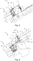
- the top profile element 11 of the fixed panel 1 is connected to the roof surface 6' by means of the mounting and hinge assembly including the installation profile 8 which is fastened to a fitting 63'.
- a top end flashing 7' is shown in Fig. 5 .
- the panel system 3 comprises two panels installed in extension of each other in the direction of inclination of a pitched surface of the panel system.
- the first openable panel 2 is shown in a stepped configuration relative to a second openable panel 200.
- the top profile element 21 of the first openable panel 2, and a bottom profile element 224 of the second openable panel 200 are connected to a supporting structure comprising a beam 6".
- the second openable panel 200 can be opened by mechanical means such as an actuator 60.
- the actuator 60 can be a chain actuator, a spindle actuator, a locking actuator, or a louvre actuator and may be powered by a DC motor.
- the openable panels 2, 200 can also be opened and closed by manual means such as an operating handle, or winding gear.
- the openable panels 2, 200 may be actuated by electromechanical means such as a switch, remote control, or at least one sensor measuring e.g. pollution, the temperature, or an air component such as humidity, or CO 2 , on the interior and/or the exterior of the openable panels 2, 200.
- the actuator 60 is connected to a cross-bar 61, placed beneath the openable panel 200 for transferring force onto the openable panel 200 to be lifted.
- the cross-bar 61 extends between the two side profile elements (not shown, corresponding to side profile elements 22, 23 of the openable panel 2) of the second openable panel 200 and acts as a yoke distributing the load from the actuator 60 and operating element such as a chain (not shown).
- the actuator 60 is connected to the beam 6" providing the supporting structure to withstand the thrust from the actuator 60.
- the beam 66" also constitutes the supporting structure of the top portion of the first openable panel 2, as the top profile element 21 is connected to a fitting 63" by means of the mounting and hinge assembly including the installation profile 8.
- the installation configuration at the top portion of the second openable panel 200 may for instance be formed as in Fig. 2 or Fig. 5 .
- the bottom portion of the first openable panel 2 may for instance be formed as in Fig. 3 or Fig. 4 .
- outer, inner etc. should be interpreted in the following manner: The outer direction points away from the interior of the building, while the inner direction points towards the interior of the building.
- interior and exterior are used hereafter to define whether an element is positioned inside or outside a structure, respectively, including directions towards the inside and the outside, respectively.
- a fourth installation configuration is shown, in which the lefthand side portion of the panel system 3 is shown connected to a supporting structure comprising roof surface 6'.
- a mounting bracket 62 is shown, connecting the side profile element 12 of the fixed panel 1 to the roof surface 6'.
- a cover at the side in the form of a side cover 33 is provided.
- the profile elements 21, 22, 23, 24 of the openable panel 2 are constructed in substantially the same way as the profile elements 11, 12, 13, 14 of the fixed panel 1.
- the general design of the profile elements is the same for the top, bottom and side profile elements of both fixed and openable panels, whereas the choice of material composition and design of the workable material can be varied from profile element to profile element as the side profile elements in a rectangular structure will, however, be designed in a mutually alike way.
- the panelling element 5 is here formed by a two-layer IGU (insulating glazing unit) 15 comprising an interior pane sheet 17 facing downwards towards an interior of a building in the shown installed position of the panel system and an exposed exterior pane sheet 16 facing in the opposite direction towards the exterior.
- each profile element here with reference to side profile element 22 of the openable panel 2
- the profile member 10 comprises a cover portion 18 and a support portion 19.
- the cover portion 18 comprises an abutment surface 181 to abut on an exterior side of the exterior pane sheet 16.
- the abutment surface 181 is provided with indentations 183.
- the support portion 19 comprises an abutment surface 191 to abut on an interior side of the interior pane sheet 17.
- the abutments surface 191 is provided with indentations 193.
- the support portion 19 furthermore comprises a hollow 194.
- the indentations 183, 193 increases the surface area of the respective abutment surface 181, 191 and as such improve the contact between a respective sealing strip 313, 314 in contact with the panelling element 5. It is preferable that the sealing strips 313, 314 has structural properties, i.e. that the contribute to the strength of the fixed panel 1 and openable panel 2.
- the pointed end 182 of the cover portion 18 functions as a drip cap and guides water onto the panelling element 5, here the two-layer IGU 15 and three-layer IGU 15', respectively.
- the side profile element 22 further comprises an insulating member 20, which comprises a thermal insulation material to reduce heat losses through the openable panel 2.
- the openable panel in an open position results in large heat losses, which are reduced through the profile element itself.
- the insulating member 20 is connected to the profile member 10, between the cover portion 18 and the support portion 19, and is positioned such that an edge of the IGU 15 is at least partially covered by the insulating member 20.
- the insulating member 20 comprises polyurethane foam (PUR), which in addition to insulating thermally, also prevents condensation. PUR avoids the formation of condensation in the insulating member 20, on the interior surfaces of the profile elements and/or on the surfaces of the IGU 15.
- the insulation material may be a material which has a lower thermal conductivity compared to its environment, whereby the insulation material reduces heat transfer between the surroundings of the insulation material. The provision of the insulating member comprising insulation material may thus significantly or substantially reduce heat transfer through the panel to or from the environment of the panel system.
- Typical insulation materials used in building construction and/or for manufacturing skylights, roof windows or panels are fiberglass, mineral wool, cellulose, natural fibres, foamed or expanded plastic polymers, polystyrene, such as expanded polystyrene (EPS), polyisocyanurate, polyurethane, vermiculite and perlite, urea-formaldehyde foam, cementitious foam and phenolic foam.
- polystyrene such as expanded polystyrene (EPS), polyisocyanurate, polyurethane, vermiculite and perlite, urea-formaldehyde foam, cementitious foam and phenolic foam.
- EPS expanded polystyrene
- a plurality of gasket tracks 30 are provided for reception of gaskets 311, 312 for sealing an edge portion of the IGU 15. Further tracks are provided as well, as will be described in more detail in the below Fig. 9 showing a second embodiment of the panel system 3 and to Figs 10 to 15 describing the drainage assembly 4 in more detail.
- profile elements 11, 12, 13, 14 and 21, 22, 23, 24 can be designed integrally and comprise other materials, e. g. wood.
- a connecting element 50 is present at an interior transition between the opposing fixed panel 1 and fixed panel 100.
- Fig. 9 shows a second embodiment of the panel system 3, in a view corresponding to Fig. 8 of the first embodiment.
- the panel system 3 of the second embodiment also comprises one or more fixed panels and one or more openable panels, of which neighbouring fixed panel 1 and openable panel 2 are shown.
- the panelling element 5 comprises a three-layer IGU 15', with three glass pane sheets, such that the three-layer IGU 15' further comprises an intermediate pane sheet 16a in addition to the exterior pane sheet 16 and the interior pane sheet 17.
- the insulating member 20 is an elongated element, comprising projections 20a at both ends.
- the insulating member 20 has a thickness T, extending in an axial direction A, which is parallel to a plane of the surfaces of the IGU 15, namely the exterior pane sheet 16 and interior pane sheet 17.
- the insulating member 20 has a height H extending in a longitudinal direction L of the insulating member 20.
- the longitudinal direction L is perpendicular to the axial direction A and to the roof surface.
- the thickness of the insulating member is approximately 20% of the height H of the insulating member 20 in the first embodiment shown in Fig. 8 and approximately 12% in the second embodiment shown in Fig. 9 .
- the height H to length L ratio may be in the range 0.05 to 0.3, typically 0.1 to 0.2.
- a total height Ht of the profile elements of the panel system 3 is indicated in Fig. 9 .
- the profile member 10 has standard dimensions, which are the same in the first and in the second embodiments, and also throughout all profile elements 11, 12, 13, 14, 21, 22, 23, 24 in the set of profile elements of each of the fixed panel 1 and the openable panel 2.
- the height H of the insulating member 20 thus defines the total height Ht of the profile element dependent on the panelling element 5. That is, the three-layer IGU 15' of the second embodiment shown in Fig. 9 requires a taller insulating member 20, i.e. having a larger height H, than the two-layer IGU 15 of the first embodiment shown in Fig. 8 .
- other dimensions of the insulating member 20 are chosen in dependence herewith.
- the profile member 10 of the profile element 22 comprises tracks 35 to safely receive and hold the insulating member 20 in the projections 20a.
- the tracks 35 are dovetail-formed.
- a glazing bead is formed in conjunction with the gasket 312.
- the projections 20a of the insulating member 20 are formed with a T-shape.
- the projections 20a of the profile element 22 and the tracks 35 act as a tongue and groove mechanism.
- the tracks 35 are placed in the cover portion 18 and the support portion 19, respectively, of the profile member 10 of the profile element 22.
- the gap between the neighbouring side profile elements 13 and 22 is about 4 mm in the first embodiment of Fig. 8 and about 6 mm in the second embodiment of Fig. 9 .
- the width of the side profile elements 13 and 22 in the axial direction of the panel system 3, from one visible edge of the IGU 15 and 15', respectively, to the other is about 50 mm in the first embodiment of Fig. 8 and about 52 mm in the second embodiment of Fig. 9 .
- the total height Ht of the side profile elements 13 and 22 is about 74 mm in the first embodiment of Fig. 8 , and the total height Ht is about 98 mm in the second embodiment of Fig. 9 .
- each profile element here side profile element 22, is provided with a side profile track 79a and a wall profile track 79b for reception of a drainage list profile 37.
- the side profile track 79a and the wall profile track 79b are located in the support portion 19.
- the drainage list 37 is fastened to the fixed panel 1 such that the neighbouring openable panel 2 may open.
- the drainage profile 37 has at least one projecting part configured for projecting into the interspace 51 in a mounted condition as will be described in the following.
- the drainage list profile 37 shown in a cross-sectional view further carries an internal sealant strip, which has a secondary sealing lip 42 and which in a U-shaped portion 49 delimits a drain trench 45 the function of which will described below.
- the secondary sealing lip 42 extends along the width of the drain trench 45 forming projections to abut to a lower part of the profile element 22.
- the drainage list profile 37 further comprises a primary mounting sealing lip 39, which is leg shaped extending in the longitudinal direction L and is inserted into the side profile track 79a.
- the U-shaped portion 49 of the drainage list profile 37 includes a first sealing lip 38 and a second mounting sealing lip 40, which is inserted into the wall profile track 79b.
- the drainage list profile 37 further comprises a base part 41 which acts as a bottom flashing and comprises two rounded projections 43 that are shaped as semi-circles.
- the base part 41 comprises at least two plate sections, which extend away from the projecting part.
- the base part 41 is covered by a design list 53 as shown in Fig. 8 and 9 , which is a strip that is bent in its two ends so that it may cover the entire base part 41.
- the design list 53 has an overall slight curvature.
- the rounded projections 43 provide for support, clearance to the base part 41 and pre-biasing of the design list 53 to avoid formation of wrinkles of the design list 53.
- the top profile element 11, 21 of each panel 1, 2 is connected to a supporting structure by means of a mounting and hinge assembly including an installation profile 9 to be described in further detail below.
- a connecting element 50' is present at an interior transition between the opposing fixed panel 1 and fixed panel 100.
- the drainage assembly 4 has an outer sealing plane and an inner sealing plane as will be described in further detail below.
- an outer top gasket 36 is located at the upper part of two neighbouring panels 1, 2 as shown in Figs 8-9 .
- the outer top gasket 36 is positioned inside an interspace 51 between the neighbouring panels 1, 2.
- the outer top gasket 36 has at least one projecting part configured for projecting into the interspace 51 in a mounted condition as will be described in the following.
- the outer top gasket 36 comprises a plate portion 67 and a leg portion 68.
- the leg portion 68 forms an angle with the plate portion 67.
- the leg portion 68 comprises two leg projections 69, which are substantially parallel to each other in an undeformed state of the gasket and form a positive angle with the leg portion 68.
- the leg portion 68 further comprises a hook-like projection 76 to be received in a top gasket track 78 on a wall surface 77 of the side profile element 22, which faces towards the interspace 51 in the mounted state.
- the leg portion 68 has a slightly arrow shaped peak 68a which has a function as a dripping nose making a controlled delivery of water droplets to the under lying trench 45.
- Said top gasket track 78 is best seen in Fig. 10 in the wall surface 77.
- the plate portion 67 overlaps the exterior surface of two neighbouring side profile elements 22, 13 and covers a top part of the interspace 51 between the side profile element 22 and a neighbouring element, here side profile element 13, thereby defining an outer sealing plane of the drainage assembly 4.
- the leg portion 68 abuts on the wall surface 77 of the side profile element 22.
- the leg projections 69 are adjacent to an inner surface of an opposite side profile element 13 of a neighbouring fixed panel 1, such that the leg projections 69 block water from passing down through the interspace 51.
- the interspace 51 together with the leg projections 69 thus constitute a second drain trench 65.
- the outer top gasket 36 extends over the entire length of the panels 1, 2, such that the outer sealing plane is kept unbroken over the entire length down to and by the outer side of the panel system 3, and at its end preferably projects out onto an adjacent bottom drainage list profile (not shown).
- An outer top gasket 36 and a drainage list profile 37 corresponding to those described above is also provided at the side edges of the panel system 3 as seen in Fig. 7 , where they delimit an interspace between the side profile element 12 and an auxiliary rafter 58 provide at the end of the panel system. Any water from the outside which passes over the surface of the side profile element 12 and past the outer top gasket 36, drips down into the drain trench 45 in the U-shaped portion 49 of the drainage list profile 37. The drain trench 45 thus prevents that water penetrates further in the structure past the drainage list profile 37 as also described above.
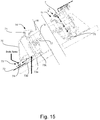
- the surface water is led, as appears from Fig. 15 , out on the roof surface and further to a not-shown roof gutter system via a cover shield 70, which is connected to the bottom profile element 14 by means of a sealant strip 71.
- the cover shield 70 may for example be made from aluminium.
- an external sealant strip 73 serving as a bottom flashing gasket is provided.
- the external sealant strip 73 also acts as a sill gasket.
- the water which reaches the drainage list profile 37 is led in the drain trench 45 along the length of U-shaped portion 49 as described in connection with Fig. 8 , and as this extends over essentially the entire panel system 3 in the direction of the roof pitch, the water can be diverted at the end of the panel system 3, as shown in Fig. 15 . Then, the water can be diverted further out past the external sealant strip 73 placed under the bottom profile element 14 via drain holes 74 the external sealant strip 73, which are mutually distanced in the axial direction A.
- the inner sealing plane is thus defined by at least three gaskets, here provided on the drainage list profile 37 and the external sealant strip 73 arranged so that two of them abut on a lower part of two side profile elements 12, 13, 22, 23 and one is positioned under the bottom profile element 14, 24 when seen in a direction from the exterior towards the interior.
- the external sealant strip 73 comprises a projecting, split flange portion 73b, a base portion 73a and a support member 73c.
- the base portion 73a is a flat strip that is adjacent to the roof structure and is usually placed onto a supporting structure for e.g. roof tiles, the panel system 3 and/or flashing elements.
- the support member 73c is a sealing member that supports the lower part of the bottom profile element 14, while it blocks any condensation or other water coming from the interior side.
- the support member 73c is shaped as a semicircle and comprises an elastic material.
- the split flange portion 73b is connected to a bottom flashing 72, which is further connected to the roof surface.
- the bottom flashing 72 acts as a flashing element, covering a barrier sheet (not shown), so that humidity does not penetrate into the roof structure.
- top profile element 11 A similar configuration is found on the top profile element 11.
- the top flashing is connected to the upper part of the top profile element 11.
- the water is diverted out at the end of the system through an inner gasket 75.
- the inner gasket 75 is positioned at the upper end of the drain trench 45 when seen in the direction of the slope of the panel system 3 and is connected to the top profile element 11.
- the gaskets 34, 36, 37, 75 may comprise ethylene-propylene diene monomer (EDPM) gasket known for its good resistance to water, sun and outdoor weather conditions.
- EDPM ethylene-propylene diene monomer
- Each gasket is preferably made in one, for example by extrusion, but it is also possible to interconnect or co-extrude two or more gasket to form one of the gaskets described above, for example if different parts of a gasket is to be made from different materials.
- the sealant strip 71 acts as a drain element. Water led along the second drain trench 65 and the drain trench 45 is led down to the end of the superimposed panel system and onto the external sealant strip 73.
- the profile element 14 is adjacent to an insulation foam member 70a, which is attached to the cover shield 70.
- the profile element 14 is mounted onto the roof via roof mounting brackets (not shown).
- the water is diverted via a top flashing gasket 34.
- the top profile element 21 abuts the inner gasket 75, which is connected to a bottom extension element 97 of the installation profile 9.
- the bottom extension element 97 will be described in detail further below.
- the top flashing gasket 34 which is better seen in Fig 13 , comprises a first leg 52 extending towards the interior. The first leg 52 is placed in a track 78 in the cover portion 18 for making a sealing connection between the first leg 52 and the cover portion 18. The track may alternatively be a recess, perforation or the like.
- a second leg 54 of the top flashing gasket 34 extends away from the panel, parallel to the major surfaces of IGU 15, underneath a top flashing 7.
- the top flashing 7 is situated above the installation profile 8.
- the top flashing 7 may extend from the top of the panels 1, 2, from a roof surface, or as seen in Fig. 6 , from an upper panel towards a lower panel.
- the top flashing 7 has a bend on the middle of about 120 degrees.
- the top flashing 7 may cover two installed fixed panels 1, 100 in the roof.
- the top flashing 7 is provided for protecting the components of the panel system 3 positioned beneath it by guiding precipitation onto the panels 1, 2, 100, 200 of the panel system 3.
- a third leg 31 of the top flashing gasket 34 extends towards the openable panel 2 to cover the components below.
- the top flashing gasket 34 under the top flashing 7, has a bend 29 extending in a direction away from the interior for avoiding accumulation of water e.g. under the top flashing 7 or for avoiding water entering the components below.
- the structure of the mounting and hinge assemblies of the panel systems of the first embodiment and of the second embodiment are different, however.
- the installation profile 8 of the fixed panel 1 of the panel system 3 of the first embodiment comprises a main body 80. At a first, interior end of the main body 80, a bottom leg 82 is provided to extend towards the top profile element 11 of the fixed panel 1. From the bottom leg 82, engagement means are provided for connection to a bottom extension element.
- the engagement means comprise two interior legs 89 extending towards the interior and configured to be connected to the bottom extension element in the form of a bottom insulating profile 48 as shown.
- the two interior legs 89 are connected to the bottom insulating profile 48 through a hook-like portion 84 terminating at the most interior end of each interior leg 89.
- the bottom insulating profile 48 comprises two exterior legs 489 forming the counterpart engagement means to the interior legs 89 of the installation profile.
- the bottom insulating profile 48 comprises a gasket engagement flange 481 for the inner gasket 75.
- a top leg 81 extends away from the fixed panel 1, in the installation configuration shown in Fig. 2 towards the ridge of the panel system 3.
- the top leg 81 is parallel to the top flashing 7.
- the top leg 81 has a flashing engagement portion 85 for connecting with the top flashing gasket 34 and the top flashing 7. The connection between the top flashing 7, the top flashing gasket 34 and the flashing engagement portion 85 takes place by means of fastener 46.
- the main body 80 is provided with a hook-shaped leg 83 extending towards the top profile element 11 of the fixed panel 1.
- the hook-shaped leg 83 of the installation profile 8 constitutes a first hinge part of the mounting and hinge assembly.
- the hook-shaped leg 83 is configured to be connected to a hook-shaped element 32 connected to the top profile element 11 of the fixed panel 1, such that the hook-shaped element 32 constitutes a second hinge part of the mounting and hinge assembly.
- the hook-shaped leg 83 and the hook-shaped element 32 together form a hinge which is the same irrespectively of the panel is openable or fixed.
- the hook-shaped element 32 comprises a base part 32a with a hook portion 32b.
- the base part 32a has a first end 32c connected to the top profile element 11 and a second opposite end 32d facing a wall 88a of the installation profile 8.
- the hinge clearance Hc is approximately 13% of the total height Ht of the profile element in the embodiment shown in Fig. 2 .
- the hinge clearance Hc to total height Ht of the profile element ratio may be in the range 0.05 to 0.3, typically 0.1 to 0.2.
- the hook-shaped leg 83 forms a curve towards the interior and terminates in an end facing the exterior, while the hook-shaped element 32 forms a curve towards the exterior and terminates in an end facing the interior.
- the fixed panel 1, and any openable panel 2 of the panel system 3 is installed by placing the panel perpendicular to the plane of the roof surface and engaging the hook-shaped element 32 with the hook-shaped leg 83 on the installation profile 8 of the mounting and hinge assembly, and rotating the panel into place to a closed position of the fixed panel 1 or the openable panel 2.
- the attachment of the hook-shaped element 32 to the hook-shaped leg 83 is thus without the use of fasteners such as bolts and can only be detached by reversing the process of mounting i.e. by rotating the panel into a position perpendicular to the roof surface.
- the fixed panel 1 remains in the closed position, while the openable panel 2 is connected to suitable operator means.
- a second side of the main body 80 faces the opposite of the first side.
- the second side is configured for connecting the installation profile 8 to a supporting structure, for instance a roof surface as in the installation configuration of Fig. 5 , a beam as in the installation configuration of Fig. 6 , or here, to the second fixed panel 100.
- the connection to the second fixed panel 100 is provided by means of a support element 44.
- the installation profile 8 is connected to the support element 44 by means of a bolt 86 received in an enlarged portion 87 of the main body 80 of the installation profile 8 and introduced into a flange portion 44a of the support element 44.
- the first end 32c of the hook-shaped element 32 may be standing on the upper surface 87a of the enlarged portion 87 during attachment or detachment of a fixed panel 1 or an openable panel 2.
- the second fixed panel 100 is a mirrored version of the first fixed panel 1 forming an obtuse angle with the fixed panel 1 as shown in Fig. 2 .
- the installation profile 8 of the fixed panel 1 of the panel system 3 of Fig. 2 has a hollow 88.
- installation profile 8 has been made with reference to fixed panel 1, the structure of the mounting arrangement is the same for openable panel 2. This means that one and the same installation profile 8 may be provided to extend in an axial direction A of the panel system 3, throughout one or more panels of the panel system 3, including one or more fixed panels 1 and one or more openable panels 2.
- the length of the installation profile 8 depends on the installation configuration and also of the dimensions including weight of the panels. Typical maximum lengths of the installation profile 8 are 3 to 6 m.
- Fig. 16 depicts the mounting and hinge assembly including the installation profile 9 of the openable panel 2 of the second embodiment of the panel system 3, i.e. in which the panelling element 5 of Fig. 1 comprises a three-layer IGU 15'.
- the installation profile 9 of the fixed panel 1 and the openable panel 2 of the panel system 3 of the second embodiment comprises similar features.
- the installation profile 9 extends in the axial direction A of the panel system 3. As in the first embodiment, the length of the installation profile 9 depends on the installation configuration of the dimensions including weight of the panels. Typical lengths range between the width of a single panel up to a maximum length of about 3 to 6 m.
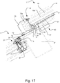
- the mounting and hinge assembly including the installation profile 9 of the panel system 3 of the second embodiment is used in various installation configurations, including a stepped configuration as shown in Fig. 17 , and also including various support structures as described for the first embodiment.
- the relationship between the installation profile 9 and the support structure in the installation configuration of Fig. 16 is shown in more detail in Fig. 18 .
- the installation profile 9 comprises a main body 90 provided with recesses for receiving means for connection and/or fastening to a support structure including neighbouring elements and to the fixed panel 1 and the openable panel 2 of the panel system 3.
- the top leg 91 of the installation profile 9 is positioned towards the second, exterior end of the main body 90 and a bottom leg 92 is positioned towards the first, interior end of the main body 90.
- a first side of the main body 90 of the installation profile 9, facing the openable panel 2 comprises two panel facing recesses 93.
- the exterior panel facing recess of the two panel facing recesses 93 is fastened with a fastener to a hinge 25 to be described in further detail below and the interior recess is left unused.
- a second side of the main body 90 of the installation profile 9, facing the opposite, comprises an accommodation recess 95 configured to receive a support element leg 44b extending from the support element 44.
- the support element leg 44b forms an oblique angle relative to a major surface of the support element 44 such that the support element 44b hooks into the accommodation recess 95.
- the support element 44 is connected to the exterior side of the installation profile recess via fasteners 96 which may be in the form of bolts.
- the bottom leg 92 extends towards the top profile element 21, parallel to the major surfaces of the IGU 15'.
- the geometry of installation profile 9 facing the openable panel 2 is for making space for the hinge 25. Possibly, also other elements of the openable panel 2 may be accommodated at the side facing the openable panel 2.
- the side of the installation profile 9 facing the openable panel 2 is configured for abutting a hinge profile flange 28 of said hinge 25 and an exterior surface of the bottom leg 92 is for abutting a profile flange leg 281 of said hinge 25.
- the bottom leg 92 comprises an interior leg 99 extending towards the interior and substantially parallel with the main body 90 of the installation profile 9.
- the interior leg 99 comprises a hook-like portion 94 for connecting to the bottom extension element 97.
- a cut-out 92a for receiving a mating end of the bottom extension element 97.
- the bottom extension element 97 includes exterior legs 979 and a gasket engagement flange 971.
- a top extension element 98 is connected to the top leg 91.
- the top extension element 98 comprises two snap fit legs 981 for connecting to the top leg 91.
- the top extension element 98 comprises a top extension element recess 982 for receiving the top flashing gasket 34 and fastener 43. As seen in Fig. 16 , such fastener 43 is for entering from the exterior through the top flashing 7, through the top flashing gasket 34, the top extension element 98 and into and through the installation profile 9, to secure a tight and sealed installation of the installation profile 9 and top flashing 7 in the roof opening.
- the hinge 25 is positioned between the openable panel 2 and the installation profile 9 for allowing the openable panel 2 to be rotated, around an axis of the hinge 25, between a closed position and an open position.
- fixed panels 1 as well as openable panels 2 of the panel system 3 in the second embodiment comprises such a hinge 25 regardless of the panel being openable or fixed.
- the hinge 25 also serves as a connection element between the installation profile 9 and the top profile element 11, 21 of each of the fixed panel 1 and openable panel 2.
- the hinge 25 comprises a hinge journal part 26 designed as a bush or barrel mounting 26a meant for reception of a hinge pin 26b, said hinge pin 26b can form part of the openable panel, whereby the hinge pin defines a hinge axis, whereabout the openable panel structure may be rotated.
- the openable panel 2 may be rotated up to 100 degrees outwards from the closed position.
- the hinge 25 has a hinge panel flange 27 connected to the openable panel 2.
- the hinge panel flange 27 is an elongated element, with a first flat side facing the top profile element 21 and a second side with a cut-out.
- the hinge panel flange 27 has means for fasteners (such as screws, not shown in detail) for being connected to the top profile element 21.
- the hinge 25 has the hinge panel flange 28 for connecting with the installation profile 9.
- the hinge profile flange 28 is substantially a mirrored version of the hinge panel flange 27 and comprises means for being fastened to the installation profile 9.
- the hinge panel flange 27 and the hinge profile flange 28 face each other in a closed position of the openable panel 2 and are aligned such that the most interior surface of the flanges 27, 28 are substantially flush in the plane of the IGU 15'.
- the hinge panel flange 27 has a panel flange leg 271 extending substantially perpendicular to a major surface of the hinge panel flange 27 towards the hinge profile flange 28.
- the hinge profile flange 28 has the profile flange leg 281 extending substantially perpendicular to a major surface of the hinge profile flange 28 towards the hinge panel flange 27.
- the profile flange leg 281 is a mirrored version of the panel flange leg 271 and the two legs face each other in a closed position of the panel.
- the legs are cuboid or plate-shaped with a chamber on an outer edge. The legs are at the most interior edge of the flanges 27, 28.
- the panel flange leg 271 is in proximity to the bottom leg 92 of the installation profile 9, extending in the plane of the IGU 15' beneath the hinge 25.
- An edge 272 of the panel flange leg 271 and an edge 282 of the profile flange leg 281 may be in abutment, in the closed position.
- the abutment between the edges 272, 282 can act as means for stopping the hinge 25 from over closing, which would damage the inner gasket 75 connected to the bottom extension element 97, when the openable panel 2 is rotated from an open position to a closed position.
- the edges 272, 282 can act as means for stopping, by the edge 272 of the panel flange leg 271 coming into contact with the edge 282 of the profile flange leg 281, as the panel is rotated towards the closed position, and thus, cause the movement of the panel to stop through friction and/or by increasing the resistance of the closing panel.
- This may protect the hinge 25 from damage, wear less on the hinge, and/or ensure a long-lasting hinge. Further, it may reduce the force needed for moving the hinge 25 from a closed position to an open position, and/or allow for more variance in the components of the hinge 25.
- the resistance may also provide the openable panel 2 with a soft close by decelerating the rotating window before reaching the closed position e.g. if at least one of the edges 272, 282 is made of a soft material such as silicone or rubber.
- the openable panel 2 comprises a shading 55 on the interior side of the interior pane 17.
- the shading 55 has a first compressed state and a second extended state wherein it can shade for light from the outside and in or the opposite way.
- the shading 55 may also be able to have a third state between the first compressed state and the second extended state.
- the shading 55 is provided with a shading bracket 56 for attaching the shading 55 to the support portion 19 of the top profile element 21.
- the shading bracket 56 is provided with a connecting element 59 with a first end for connecting with the support portion 19 and a second end providing a flat surface for connecting with the shading bracket 56.
- the shading bracket 56 and the shading 55 are connected to the top profile element 21.
- the shading 55 may also be attached to a fixed panel 1.
- the shading 55 in an installed position, is above an interior profile element plane 57 closest to the interior, in the direction of the inclined roof structure.
- the compact shading 55 being above the most interior profile element plane 57 provides an almost hidden shade, that only overlaps a small portion of the IGU 15', in the compressed state, and thus, allows more light to flow in through the IGU 15'.
- the compact shading 55 allows easier packaging, easier installation, and other extension parts or to the like to abut the interior profile element plane 57 without influencing the function of the shade.
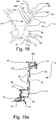
- the installation profile 9 is shown with top extension element 98 and bottom extension element 97 as separate elements connected to the main body 90 of the installation profile 9 as shown in Fig. 19a .
- top extension element 98 and bottom extension element 97 are border sections in connection with the main body 90.
- Such border sections can for instance be integral with the main body 90, such that the entire installation profile is able to be extruded of a metallic material or another material with the necessary properties such as pultruded fiberglass encapsulated in PUR, epoxy or a combination of these.
- the position of such integral border sections 970 and 980 in installation profile 9' is shown in Fig. 19b .
- the border sections 970 and/or 980 is/are cut off, for instance by milling, leaving the main body 90 in place, with a similar configuration as in Fig. 19a , including engagement means.
- a bottom extension element and/or a top extension element of suitable thermal insulation properties is/are connected to the main body 90 of the installation profile 9' via the engagement means. While such a bottom extension element or top extension element of improved thermal insulation properties are not shown in Fig. 19b , they correspond to the bottom extension element 97 and the top extension element 98 of Fig. 19a and thus perform similar functions as the counterparts of Fig. 19a .
- the panel system 3 is adapted, for instance to particular climate regions, by the following steps:
- a method of manufacturing a panel of the panel system 3 as described in the above will be described. It is noted that the fixed panel 1 and the openable panel 2 are manufactured substantially in the same way.
- the method of manufacturing a panel is carried out by the following fundamental steps:
- the profile element is manufactured by extrusion of a rigid material.
- the material is metallic, typically aluminium, profile.
- one large aluminium extrusion is used, i.e. step (i) of forming the profile member 10 comprises extruding an intermediate profile length comprising a bridging portion 18a connecting the support portion 19 with the cover portion 18 to form a generally U-shaped cavity delimited by the support portion 19, the bridging portion 18a and the cover portion 18 as shown in Fig. 20 .
- the generally U-shaped cavity in the middle is filled with a liquid plastic material, typically a liquid thermoset material, most commonly polyurethane (PUR), although molten free flowing thermoplastic materials such as hot melt adhesives may also be used.
- a liquid plastic material typically a liquid thermoset material, most commonly polyurethane (PUR), although molten free flowing thermoplastic materials such as hot melt adhesives may also be used.
- the aluminium bottom of the U-shape is removed, as by milling or sawing (de-bridging), to yield the desired structural composite aluminium thermal barrier frame.
- a thermal bridge is created in the middle of the profile.
- the bridging portion 18a is de-bridged in an additional substep subsequent to step (iii) to attain the condition shown in Fig. 22 .
- the profile element can further be produced in other ways and of other materials, e. g. by roll forming of a steel plate strip or pultrusion of a carbon fibre reinforced fibre glass profile.
- the insulating member 20 substantially comprises PUR.
- the composition of the PUR in a preferred embodiment is component A Sika Force 7744 L03 DGR (polyol) and component B Sika Force 7010 (isocyanate).
- Additional indentations or holes are adapted for letting the PUR flow into in order to fixate the PUR to the aluminium profile avoiding any movements of the insulating PUR in relation to the aluminium profile.
- the indentations are made to the bottom and/or top profile cavity projections using a cutter.
- holes may be drilled in the top and/or bottom of profile cavity wall.
- a T-slot cutter may also be used to cut indentations in the top and bottom cavity projections. This method is especially attractive since, once filled and de-bridged, the composite profile looks standard without any potential cosmetic objections as there would be with the previous concepts.
- the profile length attained in step (iii) may for instance have a length exceeding the length of at least one profile element of said set of profile elements 11, 12, 13, 14, 21, 22, 23, 24 of step (iv) by a factor of at least 2.
- One suitable length is about 6 m, which is advantageous from a manufacturing, storage and economical point of view.
- step (iv) of forming said set of profile elements 11, 12, 13, 14, 21, 22, 23, 24 may carried out from a single profile length. Typically, however, more than one profile length is required.
- a number of panels 1, 2 are built in side by side. Adjacent to one openable panel 2, a wind deflector 64 is installed.
- the wind deflector 64 is formed as an element with two triangular opposing sides 641, a rectangular top 642 and a rectangular bottom end side 643, such that the upper end is substantially smaller than the lower end when seen in the direction of inclination of the panels.
- the wind deflector does not extend all the way to the top of the panel system, but it could be the case.
- the wind deflector 64 redirects wind blowing across the exterior surface of the panel system 3 near the openable panel 2 and changes the flow pattern, such that an outward flow of air and gases from the interior may escape, thus allowing the openable panel 2 of the panel system 3 to function as a smoke exit.
- the wind deflector is further provided with flanges 644, 645, 646 at the bottom end.
- One flange 644 projects from the upper edge of the bottom end side 643 and serves wind deflection purposes.
- the second flange 645 projects over a bottom flashing 72 and may serve draining purposes as well as wind deflection purposes.
- the third flange 646 projects over the cover shield 70 of the nearest panel 2 and may contribute to positioning the wind deflector in relation to the panel system.
- a side cover 33 covering the end of the panel system 3 and projecting over an upstand 6 of roof structure on which the panel system is mounted.
- FIG. 25 At the lower portion of the panel system 3 shown in Fig. 25 , the fixed panel 1 at the end of the row is shown.
- a mounting bracket 62' is present to connect the fixed panel 1 to the supporting structure 6' at the bottom profile element 14.
- One or more corresponding mounting brackets may be present at other positions along the length of the bottom profile element 14.
- the side cover 33 is installed as indicated.
- the bottom flashing 72 is now connected to the bottom profile element 14 of the fixed panel 1.
- Fig. 26 shows the installation of a cover shield 70 as the one in Fig. 17 .
- the cover shield will cover the mounting brackets 62, when it has been installed.
- the cover shield is made from sheet metal and provided with end caps 701, which close off the ends.
- Such end caps may be provided on all cover shields, i.e. at each panel of the panel system, or only at the ends of the panel system, in which case a continuous space extending over the entire width of the panel system may be present underneath the cover shields. This space may be used to accommodate wires, ventilation ducts or the like.
Landscapes
- Engineering & Computer Science (AREA)
- Architecture (AREA)
- Civil Engineering (AREA)
- Structural Engineering (AREA)
- Physics & Mathematics (AREA)
- Electromagnetism (AREA)
- Mechanical Engineering (AREA)
- Building Environments (AREA)
- Roof Covering Using Slabs Or Stiff Sheets (AREA)
Abstract
Description
- The present invention relates to a panel system comprising a number of fixed panels and a number of openable panels, each fixed panel and each openable panel comprising a frame structure composed of a set of profile elements encasing a panelling element, said frame structure including one top profile element configured to be connected to a supporting structure by means of a mounting and hinge assembly of said panel system. The invention furthermore relates to a method of adapting such a panel system.
- Panel fillets comprising fixed or openable panels arranged in pitched or flat roofs may be provided in a number of varieties and often include complicated structures in order to allow opening of the sash and to fulfil other functions, such as ventilation, waterproofing and thermal insulation, while permitting cleaning of the outside of the pane from inside the building. The varieties include roof windows of the pivoting type, the hinge axis being either located at the centre or displaced from the centre of the window, and top-hung roof windows that pivot for cleaning by means of an intermediate frame. Furthermore, water and other precipitation may enter into the window structure and penetrate under the panel system. Heat losses may also occur between the different components of the panel system structure.
- A panel system of the kind mentioned in the introduction is devised in Applicant's published international applications
WO 00/65171 A1 WO 00/65172 A1 WO 00/65173 A1 - While these solutions have proven to function well over the years, rooms for improvement exist in terms of flexibility in the design of the components and configuration of the panel system.
- With this background, it is therefore an object of the invention to provide a panel system, which is cost-effective to manufacture and in use.
- In a first aspect, this and further objects are achieved with a panel system of the kind mentioned in the introduction which is furthermore characterised in that the mounting and hinge assembly comprises an installation profile with a main body having a first, interior end and a second, exterior end, and that at least one border section is provided in connection with at least one of the first, interior end and the second, exterior end of the main body.
- Providing an installation profile, a facilitated installation has been attained. The installation profile is easy to connect to a supporting structure. Dividing the installation profile into the main body and the border section or border sections entails that a uniform main body may be utilised in a number of various installation profiles, whereas each border section may be tailored to the specific field of application of the panel system.
- In order to obtain improved flexibility, the border section or border section may be formed integral with the main body but may also constitute a separate part.
- The material of the installation profile may in principle be chosen in accordance with the specific requirements. In a presently preferred embodiment, the installation profile comprises an extruded profile of a metallic material.
- In a presently preferred embodiment, at least one of the border sections of the installation profile is exchangeable for an extension element of a thermal insulation material. This makes it possible to adapt the installation profile to the intended installation configuration and environment. Thus, in panel systems intended to be installed in a warm climate, the entire installation profile may remain intact, whereas in panel systems to be installed in colder climates, the border section or border sections may be exchanged to improve the overall thermal insulating properties of the panel system.
- In an advantageous development of this preferred embodiment, forming a mechanically simple and reliable solution, the installation profile is provided with a top leg at the second, exterior end of the main body, the top leg extending away from the top profile element of each fixed panel and each openable panel, and wherein the top leg includes engagement means for engagement with a top extension element.
- Advantageously, the top extension element comprises two snap fit legs for engagement with the top leg of the installation profile and a top extension element recess. Snap connections, whether providing a positive, form-fitting engagement or a non-positive, force-fitting engagement, are easily handled and reliable.
- In a second aspect, a method of adapting such a panel system is devised. This method comprises the steps of:
- selecting desired thermal insulation properties of the panel system,
- providing at least one extension element with suitable thermal insulation properties,
- cutting off at least one border section from the main body, and
- engaging the at least one extension element with the main body of the installation profile.
- This makes it possible to adapt the installation profile in accordance with the desired properties.
- Any advantages applying to the first aspect apply also to the second aspect and vice versa.
- Further details and advantages will appear from the appended claims and the subsequent description and drawings.
- The invention will be described in more detail below by means of non-limiting examples of embodiments and with reference to the schematic drawings, in which
-
Fig. 1 shows a general schematic perspective view a panel system according to the invention; -
Fig. 2 is a sectional view of a top portion of a first embodiment of the panel system, with a two-layer insulating glazing unit (IGU), in a pitched configuration; -
Fig. 3 is a sectional view of a bottom portion of an embodiment of the panel system, with a two-layer IGU, and with a vertical wall as substructure; -
Fig. 4 is a sectional view of a bottom portion of an embodiment of the panel system, with a two-layer IGU, and built into a roof surface as substructure; -
Fig. 5 is a sectional view of a top portion of an embodiment of the panel system, with a two-layer IGU, and built into a roof surface as substructure; -
Fig. 6 is a sectional view of a transition portion of an embodiment of the panel system including two stepped panels, each with a two-layer IGU, and with a beam as substructure; -
Fig. 7 is a sectional view of a side portion of an embodiment of the panel system, with a two-layer IGU, and built into a roof surface as substructure; -
Fig. 8 is a sectional view of two neighbouring panels in an embodiment of the panel system, each with a two-layer IGU; -
Fig. 9 is a sectional view of two neighbouring panels in an alternative embodiment of the panel system, each with a three-layer IGU; -
Fig. 10 a sectional view of a profile element of a panel in an embodiment of the panel system according to the invention; -
Figs 11 to 14 are sectional views of details in an embodiment of the panel system according to the invention; -
Fig. 15 is a sectional view of bottom and top portions of a panel in an embodiment of the panel system according to the invention, indicating the flow of water or other precipitation; -
Fig. 16 is a view corresponding toFig. 2 , but with a three-layer insulating glazing unit (IGU); -
Fig. 17 is a view corresponding toFig. 6 , but with a three-layer insulating glazing unit (IGU) and with a shading; -
Fig. 18 is a partial view, on a larger scale, of the details ofFig. 16 ; -
Fig. 19a is a schematic sectional view of an alternative embodiment of an installation profile; -
Fig. 19b is a schematic sectional view of a further alternative embodiment of an installation profile; -
Figs 20 to 23 are schematic sectional side views of steps during manufacture of a panel of a panel system in an embodiment of the invention; -
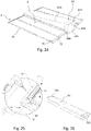
Fig. 24 is a perspective partial view of an embodiment of the panel system according to the invention; -
Fig. 25 is a partial perspective view of a lower portion of a panel of a panel system in an embodiment of the invention; and -
Fig. 26 is an exploded partial perspective view of a lower portion of a panel of a panel system in an embodiment of the invention. - Referring initially to
Fig. 1 , embodiments of apanel system 3 will be described in further detail. - The
panel system 3 can for instance be designed to form part of a panel fillet or another major panel surface which in the shown embodiment constitutes at least one part of a glass roof. - The
panel system 3 comprises a number offixed panels 1 and one or moreopenable panels 2. Eachfixed panel 1 and eachopenable panel 2 comprises usually an orthogonal, or square, frame structure forming an essentially rectangular frame structure composed of a set of profile elements. In the embodiments shown, four profile elements are provided, namely atop profile element 11, twoside profile elements bottom profile element 14 of thefixed panel 1 and correspondingly atop profile element 21, twoside profile elements 22 and abottom profile element 24 for theopenable panel 2. Theopenable panel 2 is at itstop element 21 hingedly connected to a supporting structure in a manner to be described in further detail below. - The
panel system 3 may, at most, comprise as manyopenable panels 2 as fixedpanels 1 or may comprise feweropenable panels 2 than fixedpanels 1. It is also possible to configure thepanel systems 3 with only fixedpanels 1. - Each fixed
panel 1 and eachopenable panel 2 comprises apanelling element 5. In the embodiments shown, thepanelling element 5 comprises an insulating glazing unit, or IGU. - In alternative embodiments, the
panelling element 5 may comprise or be replaced by any of a photovoltaic element e.g. solar cells, a blinded element, an IGU with built-in shading e.g. venetian blind, a panelling element filled with aerogel and/or a combination of these. - The
panels panel system 3 can be used for many other different geometrical constructions and thus have another shape than the shown rectangle, e.g. a triangular or another polygonal shape. The hinged connection can further be provided at the bottom element or one of its side elements. Thepanels - The principles of the structure of the profile elements will now be described with reference to a first embodiment. It is noted that the structure of the described profile element could in principle apply to any one of the
top profile element 11, the twoside profile elements bottom profile element 14 of the fixedpanel 1, and of thetop profile element 21, the twoside profile elements bottom profile element 24 for theopenable panel 2. - The description of the
top profile element 11 will be made with reference to the cross-sectional view shown inFig. 2 of the fixedpanel 1 and a second fixedpanel 100, positioned oppositely to the fixedpanel 1. The fixedpanel 1 and the second fixedpanel 100 may form part of apanel system 3 as shown inFig. 1 , in a first installation configuration, i.e. each comprising neighbouring panels which may be openable panels, as theopenable panel 2, or further fixed panels, to form a double pitch rooflight comprising two rows of panels connected at the top portion of thepanel system 3, e.g. forming a ridge. In this installation configuration, thepanel system 3 is self-supporting since opposing panels abut each other to form a stable construction. - Furthermore, a
drainage assembly 4 is indicated inFig. 2 , the structure of which will be described in more detail further on. - The
panel system 3 is mounted to a supporting structure, which may in principle be constituted by any suitable means designed in accordance with the desired installation configuration. - In the installation configuration shown in
Fig. 1 , and also inFig. 2 , opposing panels support each other at thetop profile elements respective panels - In general, the
top profile element panel installation profile 8 to be described in further detail below. - In
Fig. 3 , the bottom portion of thepanel system 3 is shown in connection with a supporting structure in the form of avertical wall 6, which corresponds to the first configuration shown inFig. 1 and inFig. 2 . InFig. 3 , thebottom profile element 14 of the fixedpanel 1 is thus shown. - In the below description of alternative installation configurations, reference to the panel system will be made by
reference numeral 3, and the components of thepanel system 3 will be referred to as in the above, first installation configuration for reasons of simplicity. - An alternative, second installation configuration is shown in
Fig. 4 , in which the bottom portion of thepanel system 3 is built into a supporting structure in the form of a roof surface 6'. Correspondingly, the top portion of this other panel system is shown inFig. 5 , also with the roof surface 6'. Thetop profile element 11 of the fixedpanel 1 is connected to the roof surface 6' by means of the mounting and hinge assembly including theinstallation profile 8 which is fastened to a fitting 63'. A top end flashing 7' is shown inFig. 5 . - In a further alternative, third installation configuration shown in
Fig. 6 , thepanel system 3 comprises two panels installed in extension of each other in the direction of inclination of a pitched surface of the panel system. Here, the firstopenable panel 2 is shown in a stepped configuration relative to a secondopenable panel 200. Thetop profile element 21 of the firstopenable panel 2, and abottom profile element 224 of the secondopenable panel 200 are connected to a supporting structure comprising abeam 6". - Also indicated in
Fig. 6 is that the secondopenable panel 200 can be opened by mechanical means such as anactuator 60. Theactuator 60 can be a chain actuator, a spindle actuator, a locking actuator, or a louvre actuator and may be powered by a DC motor. Theopenable panels openable panels openable panels actuator 60 is connected to a cross-bar 61, placed beneath theopenable panel 200 for transferring force onto theopenable panel 200 to be lifted. The cross-bar 61 extends between the two side profile elements (not shown, corresponding toside profile elements openable panel 200 and acts as a yoke distributing the load from theactuator 60 and operating element such as a chain (not shown). Theactuator 60 is connected to thebeam 6" providing the supporting structure to withstand the thrust from theactuator 60. - The beam 66" also constitutes the supporting structure of the top portion of the first
openable panel 2, as thetop profile element 21 is connected to a fitting 63" by means of the mounting and hinge assembly including theinstallation profile 8. - The installation configuration at the top portion of the second
openable panel 200 may for instance be formed as inFig. 2 orFig. 5 . The bottom portion of the firstopenable panel 2 may for instance be formed as inFig. 3 or Fig. 4 . - It is noted that terms such as outer, inner etc. should be interpreted in the following manner: The outer direction points away from the interior of the building, while the inner direction points towards the interior of the building. The terms interior and exterior are used hereafter to define whether an element is positioned inside or outside a structure, respectively, including directions towards the inside and the outside, respectively.
- In
Fig. 7 , a fourth installation configuration is shown, in which the lefthand side portion of thepanel system 3 is shown connected to a supporting structure comprising roof surface 6'. A mountingbracket 62 is shown, connecting theside profile element 12 of the fixedpanel 1 to the roof surface 6'. Furthermore, a cover at the side in the form of aside cover 33 is provided. - In the embodiments shown, and as appears from
Figs. 2 to 8 , theprofile elements openable panel 2 are constructed in substantially the same way as theprofile elements panel 1. Correspondingly, it applies that the general design of the profile elements is the same for the top, bottom and side profile elements of both fixed and openable panels, whereas the choice of material composition and design of the workable material can be varied from profile element to profile element as the side profile elements in a rectangular structure will, however, be designed in a mutually alike way. Thepanelling element 5 is here formed by a two-layer IGU (insulating glazing unit) 15 comprising aninterior pane sheet 17 facing downwards towards an interior of a building in the shown installed position of the panel system and an exposedexterior pane sheet 16 facing in the opposite direction towards the exterior. As shown most clearly inFig. 10 , each profile element, here with reference toside profile element 22 of theopenable panel 2, comprises, in the shown embodiment, aprofile member 10 of extruded aluminium or another rigid material such as pultruded fibreglass encapsulated in PUR or epoxy. In turn, theprofile member 10 comprises acover portion 18 and asupport portion 19. Thecover portion 18 comprises anabutment surface 181 to abut on an exterior side of theexterior pane sheet 16. Towards apointed end 182 of theabutment surface 181, theabutment surface 181 is provided withindentations 183. Thesupport portion 19 comprises anabutment surface 191 to abut on an interior side of theinterior pane sheet 17. Towards anend 192, the abutments surface 191 is provided withindentations 193. Thesupport portion 19 furthermore comprises a hollow 194. Theindentations respective abutment surface respective sealing strip panelling element 5. It is preferable that the sealing strips 313, 314 has structural properties, i.e. that the contribute to the strength of the fixedpanel 1 andopenable panel 2. - The
pointed end 182 of thecover portion 18 functions as a drip cap and guides water onto thepanelling element 5, here the two-layer IGU 15 and three-layer IGU 15', respectively. - The
side profile element 22 further comprises an insulatingmember 20, which comprises a thermal insulation material to reduce heat losses through theopenable panel 2. The openable panel in an open position results in large heat losses, which are reduced through the profile element itself. The insulatingmember 20 is connected to theprofile member 10, between thecover portion 18 and thesupport portion 19, and is positioned such that an edge of theIGU 15 is at least partially covered by the insulatingmember 20. - The insulating
member 20 comprises polyurethane foam (PUR), which in addition to insulating thermally, also prevents condensation. PUR avoids the formation of condensation in the insulatingmember 20, on the interior surfaces of the profile elements and/or on the surfaces of theIGU 15. The insulation material may be a material which has a lower thermal conductivity compared to its environment, whereby the insulation material reduces heat transfer between the surroundings of the insulation material. The provision of the insulating member comprising insulation material may thus significantly or substantially reduce heat transfer through the panel to or from the environment of the panel system. - Other typical insulation materials used in building construction and/or for manufacturing skylights, roof windows or panels are fiberglass, mineral wool, cellulose, natural fibres, foamed or expanded plastic polymers, polystyrene, such as expanded polystyrene (EPS), polyisocyanurate, polyurethane, vermiculite and perlite, urea-formaldehyde foam, cementitious foam and phenolic foam.
- In the
side profile element 22, a plurality of gasket tracks 30 are provided for reception ofgaskets IGU 15. Further tracks are provided as well, as will be described in more detail in the belowFig. 9 showing a second embodiment of thepanel system 3 and toFigs 10 to 15 describing thedrainage assembly 4 in more detail. - It is to be understood that the
profile elements - Finally, a connecting
element 50 is present at an interior transition between the opposing fixedpanel 1 and fixedpanel 100. -
Fig. 9 shows a second embodiment of thepanel system 3, in a view corresponding toFig. 8 of the first embodiment. Thepanel system 3 of the second embodiment also comprises one or more fixed panels and one or more openable panels, of which neighbouring fixedpanel 1 andopenable panel 2 are shown. In this second embodiment, thepanelling element 5 comprises a three-layer IGU 15', with three glass pane sheets, such that the three-layer IGU 15' further comprises anintermediate pane sheet 16a in addition to theexterior pane sheet 16 and theinterior pane sheet 17. - As shown in
Figs 8 and 9 , the insulatingmember 20 is an elongated element, comprisingprojections 20a at both ends. The insulatingmember 20 has a thickness T, extending in an axial direction A, which is parallel to a plane of the surfaces of theIGU 15, namely theexterior pane sheet 16 andinterior pane sheet 17. The insulatingmember 20 has a height H extending in a longitudinal direction L of the insulatingmember 20. The longitudinal direction L is perpendicular to the axial direction A and to the roof surface. The thickness of the insulating member is approximately 20% of the height H of the insulatingmember 20 in the first embodiment shown inFig. 8 and approximately 12% in the second embodiment shown inFig. 9 . In general, the height H to length L ratio may be in the range 0.05 to 0.3, typically 0.1 to 0.2. - A total height Ht of the profile elements of the
panel system 3 is indicated inFig. 9 . ComparingFig. 9 withFig. 8 , it is seen that theprofile member 10 has standard dimensions, which are the same in the first and in the second embodiments, and also throughout allprofile elements panel 1 and theopenable panel 2. The height H of the insulatingmember 20 thus defines the total height Ht of the profile element dependent on thepanelling element 5. That is, the three-layer IGU 15' of the second embodiment shown inFig. 9 requires a taller insulatingmember 20, i.e. having a larger height H, than the two-layer IGU 15 of the first embodiment shown inFig. 8 . Correspondingly, in case anotherpanelling element 5 of alternative dimensions is chosen, other dimensions of the insulatingmember 20 are chosen in dependence herewith. - As also shown more clearly in the below
Fig. 10 , theprofile member 10 of theprofile element 22 comprisestracks 35 to safely receive and hold the insulatingmember 20 in theprojections 20a. Thetracks 35 are dovetail-formed. A glazing bead is formed in conjunction with thegasket 312. Theprojections 20a of the insulatingmember 20 are formed with a T-shape. Theprojections 20a of theprofile element 22 and thetracks 35 act as a tongue and groove mechanism. In the embodiment shown, thetracks 35 are placed in thecover portion 18 and thesupport portion 19, respectively, of theprofile member 10 of theprofile element 22. - The gap between the neighbouring
side profile elements Fig. 8 and about 6 mm in the second embodiment ofFig. 9 . The width of theside profile elements panel system 3, from one visible edge of theIGU 15 and 15', respectively, to the other is about 50 mm in the first embodiment ofFig. 8 and about 52 mm in the second embodiment ofFig. 9 . The total height Ht of theside profile elements Fig. 8 , and the total height Ht is about 98 mm in the second embodiment ofFig. 9 . - Also shown in
Fig. 10 , each profile element, hereside profile element 22, is provided with aside profile track 79a and awall profile track 79b for reception of adrainage list profile 37. In the embodiments shown, with a two-part profile member 10 of each profile element, theside profile track 79a and thewall profile track 79b are located in thesupport portion 19. Above and adjacent to theprofile track 79b there is asmall dripping nose 19a designed in a way to securely make a controlled delivery of water droplets to the under lyingtrench 45. Thedrainage list 37 is fastened to the fixedpanel 1 such that the neighbouringopenable panel 2 may open. Thedrainage profile 37 has at least one projecting part configured for projecting into theinterspace 51 in a mounted condition as will be described in the following. - As shown in
Fig. 12 , thedrainage list profile 37 shown in a cross-sectional view further carries an internal sealant strip, which has asecondary sealing lip 42 and which in aU-shaped portion 49 delimits adrain trench 45 the function of which will described below. Thesecondary sealing lip 42 extends along the width of thedrain trench 45 forming projections to abut to a lower part of theprofile element 22. Thedrainage list profile 37 further comprises a primarymounting sealing lip 39, which is leg shaped extending in the longitudinal direction L and is inserted into theside profile track 79a. TheU-shaped portion 49 of thedrainage list profile 37 includes afirst sealing lip 38 and a secondmounting sealing lip 40, which is inserted into thewall profile track 79b. Thedrainage list profile 37 further comprises abase part 41 which acts as a bottom flashing and comprises tworounded projections 43 that are shaped as semi-circles. Thebase part 41 comprises at least two plate sections, which extend away from the projecting part. In the mounted state thebase part 41 is covered by adesign list 53 as shown inFig. 8 and 9 , which is a strip that is bent in its two ends so that it may cover theentire base part 41. Thedesign list 53 has an overall slight curvature. Therounded projections 43 provide for support, clearance to thebase part 41 and pre-biasing of thedesign list 53 to avoid formation of wrinkles of thedesign list 53. - In general, also in the second embodiment of the
panel system 3, thetop profile element panel installation profile 9 to be described in further detail below. - Finally, a connecting element 50' is present at an interior transition between the opposing fixed
panel 1 and fixedpanel 100. - In the following, the drainage of water from the panel system will be described, mainly with reference to the first and second embodiments shown in
Figs 2 to 8 and9 , respectively, and toFigs 10 to 16 . - As the
panel system 3 is mounted in a pitched roof, surface water stemming from rain, snow or other precipitation is usually transported towards the bottom profile elements. The major part of this surface water will, of course, run over thepanels system 3, but a smaller part may enter into the space between adjacentside profile elements drain trench 45 formed by thedrainage list profile 37 as seen inFig. 8 . Thedrainage assembly 4 has an outer sealing plane and an inner sealing plane as will be described in further detail below. - To reduce the amount of water entering the space between adjacent
side profile elements top gasket 36 is located at the upper part of twoneighbouring panels Figs 8-9 . The outertop gasket 36 is positioned inside aninterspace 51 between the neighbouringpanels top gasket 36 has at least one projecting part configured for projecting into theinterspace 51 in a mounted condition as will be described in the following. - As seen in
Fig. 11 , the outertop gasket 36 comprises aplate portion 67 and aleg portion 68. Theleg portion 68 forms an angle with theplate portion 67. Theleg portion 68 comprises twoleg projections 69, which are substantially parallel to each other in an undeformed state of the gasket and form a positive angle with theleg portion 68. Theleg portion 68 further comprises a hook-like projection 76 to be received in atop gasket track 78 on awall surface 77 of theside profile element 22, which faces towards theinterspace 51 in the mounted state. Opposite theplate portion 67 theleg portion 68 has a slightly arrow shapedpeak 68a which has a function as a dripping nose making a controlled delivery of water droplets to the under lyingtrench 45. Saidtop gasket track 78 is best seen inFig. 10 in thewall surface 77. - In the mounted state of the outer
top gasket 36 theplate portion 67 overlaps the exterior surface of two neighbouringside profile elements interspace 51 between theside profile element 22 and a neighbouring element, hereside profile element 13, thereby defining an outer sealing plane of thedrainage assembly 4. Theleg portion 68 abuts on thewall surface 77 of theside profile element 22. Theleg projections 69 are adjacent to an inner surface of an oppositeside profile element 13 of a neighbouring fixedpanel 1, such that theleg projections 69 block water from passing down through theinterspace 51. Theinterspace 51 together with theleg projections 69 thus constitute asecond drain trench 65. - The outer
top gasket 36 extends over the entire length of thepanels panel system 3, and at its end preferably projects out onto an adjacent bottom drainage list profile (not shown). - Water that may penetrate past the outer
top gasket 36, either because anopenable panel 2 is open during periods with precipitation, or due to leaks in the outertop gasket 36 or condensation water or bilge water. - An outer
top gasket 36 and adrainage list profile 37 corresponding to those described above is also provided at the side edges of thepanel system 3 as seen inFig. 7 , where they delimit an interspace between theside profile element 12 and anauxiliary rafter 58 provide at the end of the panel system. Any water from the outside which passes over the surface of theside profile element 12 and past the outertop gasket 36, drips down into thedrain trench 45 in theU-shaped portion 49 of thedrainage list profile 37. Thedrain trench 45 thus prevents that water penetrates further in the structure past thedrainage list profile 37 as also described above. - At the bottom end of the
panel system 3, the surface water is led, as appears fromFig. 15 , out on the roof surface and further to a not-shown roof gutter system via acover shield 70, which is connected to thebottom profile element 14 by means of asealant strip 71. Thecover shield 70 may for example be made from aluminium. On the interior side anexternal sealant strip 73 serving as a bottom flashing gasket is provided. Theexternal sealant strip 73 also acts as a sill gasket. - The water which reaches the
drainage list profile 37 is led in thedrain trench 45 along the length ofU-shaped portion 49 as described in connection withFig. 8 , and as this extends over essentially theentire panel system 3 in the direction of the roof pitch, the water can be diverted at the end of thepanel system 3, as shown inFig. 15 . Then, the water can be diverted further out past theexternal sealant strip 73 placed under thebottom profile element 14 via drain holes 74 theexternal sealant strip 73, which are mutually distanced in the axial direction A. - The inner sealing plane is thus defined by at least three gaskets, here provided on the
drainage list profile 37 and theexternal sealant strip 73 arranged so that two of them abut on a lower part of twoside profile elements bottom profile element - As is better seen in
Fig. 14 theexternal sealant strip 73 comprises a projecting, splitflange portion 73b, abase portion 73a and asupport member 73c. Thebase portion 73a is a flat strip that is adjacent to the roof structure and is usually placed onto a supporting structure for e.g. roof tiles, thepanel system 3 and/or flashing elements. Thesupport member 73c is a sealing member that supports the lower part of thebottom profile element 14, while it blocks any condensation or other water coming from the interior side. Thesupport member 73c is shaped as a semicircle and comprises an elastic material. Thesplit flange portion 73b is connected to a bottom flashing 72, which is further connected to the roof surface. The bottom flashing 72 acts as a flashing element, covering a barrier sheet (not shown), so that humidity does not penetrate into the roof structure. - A similar configuration is found on the
top profile element 11. The top flashing is connected to the upper part of thetop profile element 11. The water is diverted out at the end of the system through aninner gasket 75. Theinner gasket 75 is positioned at the upper end of thedrain trench 45 when seen in the direction of the slope of thepanel system 3 and is connected to thetop profile element 11. - The
gaskets - At joints between superimposed panels, such as the fixed
panel 1 and theopenable panel 2 inFig 17 , thesealant strip 71 acts as a drain element. Water led along thesecond drain trench 65 and thedrain trench 45 is led down to the end of the superimposed panel system and onto theexternal sealant strip 73. - In the fixed
panel 1 ofFig. 17 , theprofile element 14 is adjacent to aninsulation foam member 70a, which is attached to thecover shield 70. Theprofile element 14 is mounted onto the roof via roof mounting brackets (not shown). - At the
top profile element 21 of theopenable panel 2 inFig. 17 and at thetop profile element 11 inFig. 15 , the water is diverted via atop flashing gasket 34. At the interior side of theprofile element 21, thetop profile element 21 abuts theinner gasket 75, which is connected to abottom extension element 97 of theinstallation profile 9. Thebottom extension element 97 will be described in detail further below. - A first end of the
top flashing gasket 34 exposed to the exterior overlaps acover portion 18 of thetop profile element top flashing gasket 34 towards theIGU 15 as may be seen inFig. 15 as well as in another embodiment inFig. 16 . Thetop flashing gasket 34, which is better seen inFig 13 , comprises afirst leg 52 extending towards the interior. Thefirst leg 52 is placed in atrack 78 in thecover portion 18 for making a sealing connection between thefirst leg 52 and thecover portion 18. The track may alternatively be a recess, perforation or the like. Asecond leg 54 of thetop flashing gasket 34 extends away from the panel, parallel to the major surfaces ofIGU 15, underneath atop flashing 7. - The
top flashing 7 is situated above theinstallation profile 8. Thetop flashing 7 may extend from the top of thepanels Fig. 6 , from an upper panel towards a lower panel. InFig. 2 , thetop flashing 7 has a bend on the middle of about 120 degrees. As seen inFig. 2 , thetop flashing 7 may cover two installedfixed panels top flashing 7 is provided for protecting the components of thepanel system 3 positioned beneath it by guiding precipitation onto thepanels panel system 3. - A
fastener 46 entering through thetop flashing 7, through the second leg of thetop flashing gasket 34 and through atop leg installation profile top flashing gasket 34 to themain body installation profile Fig. 16 , athird leg 31 of thetop flashing gasket 34 extends towards theopenable panel 2 to cover the components below. - Referring to
Figs 16-17 as well as the detailed view ofFig. 11 , thetop flashing gasket 34, under thetop flashing 7, has abend 29 extending in a direction away from the interior for avoiding accumulation of water e.g. under thetop flashing 7 or for avoiding water entering the components below. - The principles of the mounting of a
panel panel system 3 in a supporting structure will now be described with particular reference toFig. 2 showing the first embodiment, and toFig. 16 showing the second embodiment. - It is noted that the principles of mounting are the same for the fixed
panel 1 and theopenable panel 2 in thepanel system 3 in eachrespective panel system 3. The connection of thetop profile element panel 1 and theopenable panel 2 to the supporting structure is carried out by means of a mounting and hinge assembly as mentioned in the above and which will be described in further detail below. - The structure of the mounting and hinge assemblies of the panel systems of the first embodiment and of the second embodiment are different, however.
- Referring initially to
Fig. 2 , description of the mounting and hinge assembly of the first embodiment of thepanel system 3 will be made with reference to the fixedpanel 1. - The
installation profile 8 of the fixedpanel 1 of thepanel system 3 of the first embodiment comprises amain body 80. At a first, interior end of themain body 80, abottom leg 82 is provided to extend towards thetop profile element 11 of the fixedpanel 1. From thebottom leg 82, engagement means are provided for connection to a bottom extension element. In the embodiment shown, the engagement means comprise twointerior legs 89 extending towards the interior and configured to be connected to the bottom extension element in the form of a bottom insulatingprofile 48 as shown. The twointerior legs 89 are connected to the bottom insulatingprofile 48 through a hook-like portion 84 terminating at the most interior end of eachinterior leg 89. To that purpose, thebottom insulating profile 48 comprises twoexterior legs 489 forming the counterpart engagement means to theinterior legs 89 of the installation profile. Finally, thebottom insulating profile 48 comprises agasket engagement flange 481 for theinner gasket 75. - At a second, exterior end of the main body 80 a
top leg 81 extends away from the fixedpanel 1, in the installation configuration shown inFig. 2 towards the ridge of thepanel system 3. Thetop leg 81 is parallel to thetop flashing 7. Thetop leg 81 has a flashingengagement portion 85 for connecting with thetop flashing gasket 34 and thetop flashing 7. The connection between thetop flashing 7, thetop flashing gasket 34 and the flashingengagement portion 85 takes place by means offastener 46. - At the second, exterior end of the
main body 80, on a first side of themain body 80 facing towards thetop profile element 11, themain body 80 is provided with a hook-shapedleg 83 extending towards thetop profile element 11 of the fixedpanel 1. The hook-shapedleg 83 of theinstallation profile 8 constitutes a first hinge part of the mounting and hinge assembly. The hook-shapedleg 83 is configured to be connected to a hook-shapedelement 32 connected to thetop profile element 11 of the fixedpanel 1, such that the hook-shapedelement 32 constitutes a second hinge part of the mounting and hinge assembly. The hook-shapedleg 83 and the hook-shapedelement 32 together form a hinge which is the same irrespectively of the panel is openable or fixed. The hook-shapedelement 32 comprises abase part 32a with ahook portion 32b. Thebase part 32a has afirst end 32c connected to thetop profile element 11 and a secondopposite end 32d facing awall 88a of theinstallation profile 8. There is a hinge clearance He, in the direction of inclination, between thesecond end 32d and thewall 88a for safe attachment between the hook-shapedleg 83 and thehook portion 32b, such that the openable panel cannot accidentally detach during opening. The hinge clearance Hc is approximately 13% of the total height Ht of the profile element in the embodiment shown inFig. 2 . In general, the hinge clearance Hc to total height Ht of the profile element ratio may be in the range 0.05 to 0.3, typically 0.1 to 0.2. - It is noted that in the embodiment shown, the hook-shaped
leg 83 forms a curve towards the interior and terminates in an end facing the exterior, while the hook-shapedelement 32 forms a curve towards the exterior and terminates in an end facing the interior. In this way, the fixedpanel 1, and anyopenable panel 2 of thepanel system 3, is installed by placing the panel perpendicular to the plane of the roof surface and engaging the hook-shapedelement 32 with the hook-shapedleg 83 on theinstallation profile 8 of the mounting and hinge assembly, and rotating the panel into place to a closed position of the fixedpanel 1 or theopenable panel 2. The attachment of the hook-shapedelement 32 to the hook-shapedleg 83 is thus without the use of fasteners such as bolts and can only be detached by reversing the process of mounting i.e. by rotating the panel into a position perpendicular to the roof surface. After attaching the hook-shapedelement 32 to the hook-shapedleg 83, the fixedpanel 1 remains in the closed position, while theopenable panel 2 is connected to suitable operator means. - A second side of the
main body 80 faces the opposite of the first side. The second side is configured for connecting theinstallation profile 8 to a supporting structure, for instance a roof surface as in the installation configuration ofFig. 5 , a beam as in the installation configuration ofFig. 6 , or here, to the second fixedpanel 100. The connection to the second fixedpanel 100 is provided by means of asupport element 44. Theinstallation profile 8 is connected to thesupport element 44 by means of abolt 86 received in anenlarged portion 87 of themain body 80 of theinstallation profile 8 and introduced into aflange portion 44a of thesupport element 44. Thefirst end 32c of the hook-shapedelement 32 may be standing on theupper surface 87a of theenlarged portion 87 during attachment or detachment of a fixedpanel 1 or anopenable panel 2. - The second fixed
panel 100 is a mirrored version of the first fixedpanel 1 forming an obtuse angle with the fixedpanel 1 as shown inFig. 2 . - Finally, the
installation profile 8 of the fixedpanel 1 of thepanel system 3 ofFig. 2 has a hollow 88. - Although the description of the
installation profile 8 has been made with reference to fixedpanel 1, the structure of the mounting arrangement is the same foropenable panel 2. This means that one and thesame installation profile 8 may be provided to extend in an axial direction A of thepanel system 3, throughout one or more panels of thepanel system 3, including one or morefixed panels 1 and one or moreopenable panels 2. The length of theinstallation profile 8 depends on the installation configuration and also of the dimensions including weight of the panels. Typical maximum lengths of theinstallation profile 8 are 3 to 6 m. - Turning now initially to
Fig. 16 , corresponding toFig. 2 showing the first embodiment,Fig. 16 depicts the mounting and hinge assembly including theinstallation profile 9 of theopenable panel 2 of the second embodiment of thepanel system 3, i.e. in which thepanelling element 5 ofFig. 1 comprises a three-layer IGU 15'. Theinstallation profile 9 of the fixedpanel 1 and theopenable panel 2 of thepanel system 3 of the second embodiment comprises similar features. - The
installation profile 9 extends in the axial direction A of thepanel system 3. As in the first embodiment, the length of theinstallation profile 9 depends on the installation configuration of the dimensions including weight of the panels. Typical lengths range between the width of a single panel up to a maximum length of about 3 to 6 m. - The mounting and hinge assembly including the
installation profile 9 of thepanel system 3 of the second embodiment is used in various installation configurations, including a stepped configuration as shown inFig. 17 , and also including various support structures as described for the first embodiment. The relationship between theinstallation profile 9 and the support structure in the installation configuration ofFig. 16 is shown in more detail inFig. 18 . - The
installation profile 9 comprises amain body 90 provided with recesses for receiving means for connection and/or fastening to a support structure including neighbouring elements and to the fixedpanel 1 and theopenable panel 2 of thepanel system 3. Thetop leg 91 of theinstallation profile 9 is positioned towards the second, exterior end of themain body 90 and abottom leg 92 is positioned towards the first, interior end of themain body 90. - As seen most clearly in
Fig. 18 , a first side of themain body 90 of theinstallation profile 9, facing theopenable panel 2, comprises two panel facing recesses 93. In the installation configuration shown inFig. 16 , the exterior panel facing recess of the two panel facing recesses 93 is fastened with a fastener to ahinge 25 to be described in further detail below and the interior recess is left unused. - Also shown in
Figs 16 and18 , a second side of themain body 90 of theinstallation profile 9, facing the opposite, comprises anaccommodation recess 95 configured to receive asupport element leg 44b extending from thesupport element 44. Thesupport element leg 44b forms an oblique angle relative to a major surface of thesupport element 44 such that thesupport element 44b hooks into theaccommodation recess 95. InFig. 16 , thesupport element 44 is connected to the exterior side of the installation profile recess viafasteners 96 which may be in the form of bolts. - Furthermore, it is shown how the
bottom leg 92 extends towards thetop profile element 21, parallel to the major surfaces of the IGU 15'. The geometry ofinstallation profile 9 facing theopenable panel 2 is for making space for thehinge 25. Possibly, also other elements of theopenable panel 2 may be accommodated at the side facing theopenable panel 2. - The side of the
installation profile 9 facing theopenable panel 2 is configured for abutting ahinge profile flange 28 of saidhinge 25 and an exterior surface of thebottom leg 92 is for abutting aprofile flange leg 281 of saidhinge 25. Thebottom leg 92 comprises aninterior leg 99 extending towards the interior and substantially parallel with themain body 90 of theinstallation profile 9. Theinterior leg 99 comprises a hook-like portion 94 for connecting to thebottom extension element 97. At the transition between thebottom leg 92 and themain body 90 of theinstallation profile 9, a cut-out 92a for receiving a mating end of thebottom extension element 97. Thebottom extension element 97 includesexterior legs 979 and agasket engagement flange 971. - At the exterior end of the
installation profile 9, atop extension element 98 is connected to thetop leg 91. On an interior facing side of thetop extension element 98 abutting thetop leg 91 of theinstallation profile 9, thetop extension element 98 comprises two snapfit legs 981 for connecting to thetop leg 91. On an exterior facing side of thetop extension element 98, thetop extension element 98 comprises a topextension element recess 982 for receiving thetop flashing gasket 34 andfastener 43. As seen inFig. 16 ,such fastener 43 is for entering from the exterior through thetop flashing 7, through thetop flashing gasket 34, thetop extension element 98 and into and through theinstallation profile 9, to secure a tight and sealed installation of theinstallation profile 9 andtop flashing 7 in the roof opening. - Referring again to
Fig. 16 , thehinge 25 is positioned between theopenable panel 2 and theinstallation profile 9 for allowing theopenable panel 2 to be rotated, around an axis of thehinge 25, between a closed position and an open position. - It is noted that fixed
panels 1 as well asopenable panels 2 of thepanel system 3 in the second embodiment comprises such ahinge 25 regardless of the panel being openable or fixed. Thehinge 25 also serves as a connection element between theinstallation profile 9 and thetop profile element panel 1 andopenable panel 2. - The
hinge 25 comprises ahinge journal part 26 designed as a bush or barrel mounting 26a meant for reception of ahinge pin 26b, saidhinge pin 26b can form part of the openable panel, whereby the hinge pin defines a hinge axis, whereabout the openable panel structure may be rotated. Theopenable panel 2 may be rotated up to 100 degrees outwards from the closed position. - The
hinge 25 has ahinge panel flange 27 connected to theopenable panel 2. Thehinge panel flange 27 is an elongated element, with a first flat side facing thetop profile element 21 and a second side with a cut-out. Thehinge panel flange 27 has means for fasteners (such as screws, not shown in detail) for being connected to thetop profile element 21. Further, thehinge 25 has thehinge panel flange 28 for connecting with theinstallation profile 9. Thehinge profile flange 28 is substantially a mirrored version of thehinge panel flange 27 and comprises means for being fastened to theinstallation profile 9. Thehinge panel flange 27 and thehinge profile flange 28 face each other in a closed position of theopenable panel 2 and are aligned such that the most interior surface of theflanges - The
hinge panel flange 27 has apanel flange leg 271 extending substantially perpendicular to a major surface of thehinge panel flange 27 towards thehinge profile flange 28. Likewise, thehinge profile flange 28 has theprofile flange leg 281 extending substantially perpendicular to a major surface of thehinge profile flange 28 towards thehinge panel flange 27. Theprofile flange leg 281 is a mirrored version of thepanel flange leg 271 and the two legs face each other in a closed position of the panel. The legs are cuboid or plate-shaped with a chamber on an outer edge. The legs are at the most interior edge of theflanges - The
panel flange leg 271 is in proximity to thebottom leg 92 of theinstallation profile 9, extending in the plane of the IGU 15' beneath thehinge 25. Anedge 272 of thepanel flange leg 271 and anedge 282 of theprofile flange leg 281 may be in abutment, in the closed position. The abutment between theedges hinge 25 from over closing, which would damage theinner gasket 75 connected to thebottom extension element 97, when theopenable panel 2 is rotated from an open position to a closed position. Theedges edge 272 of thepanel flange leg 271 coming into contact with theedge 282 of theprofile flange leg 281, as the panel is rotated towards the closed position, and thus, cause the movement of the panel to stop through friction and/or by increasing the resistance of the closing panel. This may protect thehinge 25 from damage, wear less on the hinge, and/or ensure a long-lasting hinge. Further, it may reduce the force needed for moving thehinge 25 from a closed position to an open position, and/or allow for more variance in the components of thehinge 25. The resistance may also provide theopenable panel 2 with a soft close by decelerating the rotating window before reaching the closed position e.g. if at least one of theedges - Referring particularly to
Fig. 17 , theopenable panel 2 comprises ashading 55 on the interior side of theinterior pane 17. Theshading 55 has a first compressed state and a second extended state wherein it can shade for light from the outside and in or the opposite way. Theshading 55 may also be able to have a third state between the first compressed state and the second extended state. Theshading 55 is provided with ashading bracket 56 for attaching theshading 55 to thesupport portion 19 of thetop profile element 21. Theshading bracket 56 is provided with a connectingelement 59 with a first end for connecting with thesupport portion 19 and a second end providing a flat surface for connecting with theshading bracket 56. Theshading bracket 56 and theshading 55 are connected to thetop profile element 21. Theshading 55 may also be attached to a fixedpanel 1. Theshading 55, in an installed position, is above an interiorprofile element plane 57 closest to the interior, in the direction of the inclined roof structure. Thecompact shading 55 being above the most interiorprofile element plane 57 provides an almost hidden shade, that only overlaps a small portion of the IGU 15', in the compressed state, and thus, allows more light to flow in through the IGU 15'. Thecompact shading 55 allows easier packaging, easier installation, and other extension parts or to the like to abut the interiorprofile element plane 57 without influencing the function of the shade. - In the above-described
Fig. 18 , theinstallation profile 9 is shown withtop extension element 98 andbottom extension element 97 as separate elements connected to themain body 90 of theinstallation profile 9 as shown inFig. 19a . - However, in an alternative embodiment it is also possible to provide the geometry of the
top extension element 98 andbottom extension element 97 as border sections in connection with themain body 90. Such border sections can for instance be integral with themain body 90, such that the entire installation profile is able to be extruded of a metallic material or another material with the necessary properties such as pultruded fiberglass encapsulated in PUR, epoxy or a combination of these. The position of suchintegral border sections Fig. 19b . - While such metallic material has good strength properties, the thermal performance is not necessarily satisfying. In some climates, increased insulation is desirable. By forming the border sections exchangeable for an extension element of a thermal insulation material, the insulating properties of the installation profile 9' and thus of the entire fixed
panel 1 oropenable panel 2 is improved. - In the embodiment of
Fig. 19b , it is thus possible to utilise the installation profile 9' in the configuration indicated, i.e. where theborder sections bottom extension element 97 andtop extension element 98 as described in the above, i.e. for receivinggaskets - In case it is desirable to improve the thermal insulation properties of the installation profile 9', the
border sections 970 and/or 980 is/are cut off, for instance by milling, leaving themain body 90 in place, with a similar configuration as inFig. 19a , including engagement means. Following the cutting off, a bottom extension element and/or a top extension element of suitable thermal insulation properties is/are connected to themain body 90 of the installation profile 9' via the engagement means. While such a bottom extension element or top extension element of improved thermal insulation properties are not shown inFig. 19b , they correspond to thebottom extension element 97 and thetop extension element 98 ofFig. 19a and thus perform similar functions as the counterparts ofFig. 19a . - Although not shown, a configuration of the
installation profile 7 of the first embodiment with an integral border section to be possibly exchanged forbottom extension element 48 is conceivable as well. - In practice, the
panel system 3 is adapted, for instance to particular climate regions, by the following steps: - selecting desired thermal insulation properties of the
panel system 3, - providing at least one
extension element - cutting off at least one border section from the
main body 90, and - engaging the at least one
extension element main body 90 of the installation profile. - Referring now to
Figs 20 to 23 , a method of manufacturing a panel of thepanel system 3 as described in the above will be described. It is noted that the fixedpanel 1 and theopenable panel 2 are manufactured substantially in the same way. - The method of manufacturing a panel is carried out by the following fundamental steps:
- (i) forming a
profile member 10 of a rigid material, - (ii) forming an insulating
member 20 of a thermal insulation material, - (iii) connecting the
profile member 10 with the insulatingmember 20 to provide at least one profile length, - (iv) forming a set of
profile elements - (v) providing a
panelling element 5; 15; 15', and - (vi) connecting the set of
profile elements panelling element 5; 15; 15' to form a finalisedpanel - The profile element is manufactured by extrusion of a rigid material. In the embodiment described, the material is metallic, typically aluminium, profile. According to this method, one large aluminium extrusion is used, i.e. step (i) of forming the
profile member 10 comprises extruding an intermediate profile length comprising a bridgingportion 18a connecting thesupport portion 19 with thecover portion 18 to form a generally U-shaped cavity delimited by thesupport portion 19, the bridgingportion 18a and thecover portion 18 as shown inFig. 20 . - The generally U-shaped cavity in the middle is filled with a liquid plastic material, typically a liquid thermoset material, most commonly polyurethane (PUR), although molten free flowing thermoplastic materials such as hot melt adhesives may also be used. Thus, steps (ii) and (iii) of forming the insulating
member 20 and connecting theprofile member 10 with the insulatingmember 20 is carried out in a single operation by moulding the thermal insulation material into the U-shaped cavity delimited by thesupport portion 19, the bridgingportion 18a and thecover portion 18. This is shown inFig. 21 . - After the liquid plastic material has solidified, usually bonding to the aluminium, the aluminium bottom of the U-shape is removed, as by milling or sawing (de-bridging), to yield the desired structural composite aluminium thermal barrier frame. In this way, a thermal bridge is created in the middle of the profile. Thus, the bridging
portion 18a is de-bridged in an additional substep subsequent to step (iii) to attain the condition shown inFig. 22 . - It is also possible to use two separate aluminium profiles with the poured process by appropriate jigging and sealing the cavity bottom to eliminate the de-bridging operation. In either case, fewer operations are required to produce the finished thermal barrier profile than in the first process.
- Alternatively, the profile element can further be produced in other ways and of other materials, e. g. by roll forming of a steel plate strip or pultrusion of a carbon fibre reinforced fibre glass profile.
- According to this method, the insulating
member 20 substantially comprises PUR. The composition of the PUR in a preferred embodiment is component A Sika Force 7744 L03 DGR (polyol) and component B Sika Force 7010 (isocyanate). - Additional indentations or holes are adapted for letting the PUR flow into in order to fixate the PUR to the aluminium profile avoiding any movements of the insulating PUR in relation to the aluminium profile.
- The indentations are made to the bottom and/or top profile cavity projections using a cutter. Alternatively, holes may be drilled in the top and/or bottom of profile cavity wall.
- A T-slot cutter may also be used to cut indentations in the top and bottom cavity projections. This method is especially attractive since, once filled and de-bridged, the composite profile looks standard without any potential cosmetic objections as there would be with the previous concepts.
- The profile length attained in step (iii) may for instance have a length exceeding the length of at least one profile element of said set of
profile elements profile elements - In the embodiment of the
panel system 3 shown inFig. 24 , a number ofpanels openable panel 2, awind deflector 64 is installed. Thewind deflector 64 is formed as an element with two triangular opposing sides 641, arectangular top 642 and a rectangularbottom end side 643, such that the upper end is substantially smaller than the lower end when seen in the direction of inclination of the panels. In this embodiment the wind deflector does not extend all the way to the top of the panel system, but it could be the case. Thewind deflector 64 redirects wind blowing across the exterior surface of thepanel system 3 near theopenable panel 2 and changes the flow pattern, such that an outward flow of air and gases from the interior may escape, thus allowing theopenable panel 2 of thepanel system 3 to function as a smoke exit. - In this embodiment the wind deflector is further provided with
flanges flange 644 projects from the upper edge of thebottom end side 643 and serves wind deflection purposes. Thesecond flange 645 projects over a bottom flashing 72 and may serve draining purposes as well as wind deflection purposes. Thethird flange 646 projects over thecover shield 70 of thenearest panel 2 and may contribute to positioning the wind deflector in relation to the panel system. - Also visible in
Fig. 24 is aside cover 33 covering the end of thepanel system 3 and projecting over anupstand 6 of roof structure on which the panel system is mounted. - At the lower portion of the
panel system 3 shown inFig. 25 , the fixedpanel 1 at the end of the row is shown. A mounting bracket 62' is present to connect the fixedpanel 1 to the supporting structure 6' at thebottom profile element 14. One or more corresponding mounting brackets may be present at other positions along the length of thebottom profile element 14. The side cover 33 is installed as indicated. The bottom flashing 72 is now connected to thebottom profile element 14 of the fixedpanel 1. -
Fig. 26 shows the installation of acover shield 70 as the one inFig. 17 . As may be seen, the cover shield will cover the mountingbrackets 62, when it has been installed. In this embodiment, the cover shield is made from sheet metal and provided withend caps 701, which close off the ends. Such end caps may be provided on all cover shields, i.e. at each panel of the panel system, or only at the ends of the panel system, in which case a continuous space extending over the entire width of the panel system may be present underneath the cover shields. This space may be used to accommodate wires, ventilation ducts or the like. - The invention is not limited to the above described embodiments, and the drainage and sealing system can, of course, also be used for other types of structures than the shown
panel system 3. -
- 1
- fixed panel (first)
- 11
- top profile element
- 12
- side profile element
- 13
- side profile element
- 14
- bottom profile element
- 100
- fixed panel (second)
- 111
- top profile element
- 2
- openable panel (first)
- 21
- top profile element
- 22
- side profile element
- 23
- side profile element
- 24
- bottom profile element
- 200
- openable panel (second)
- 224
- bottom profile element
- 3
- panel system
- 4
- drainage assembly
- 5
- panelling element
- 6
- supporting structure (vertical wall)
- 6'
- supporting structure (roof surface)
- 6"
- supporting structure (beam)
- 7
- top flashing
- 7'
- top end flashing
- 8
- installation profile (first embodiment)
- 80
- main body
- 81
- top leg
- 82
- bottom leg
- 83
- hook-shaped leg
- 84
- hook-like portion of
interior leg 89 - 85
- flashing engagement portion
- 86
- fastener / bolt
- 87
- enlarged portion
- 87a
- upper surface
- 88
- hollow
- 88a
- wall
- 89
- interior legs
- 9
- installation profile (second embodiment)
- 9'
- installation profile (alternative embodiment,
Fig. 19b ) - 90
- main body
- 91
- top leg
- 92
- bottom leg
- 92a
- cut-out
- 93
- panel facing recesses
- 94
- hook-like portion of
interior leg 99 - 95
- accommodation recess
- 96
- fastener / bolt
- 97
- bottom extension element (second embodiment)
- 970
- border section
- 971
- gasket engagement flange
- 979
- exterior legs
- 98
- top extension element
- 980
- border section
- 981
- snap fit legs
- 982
- top extension element recess
- 99
- interior leg
- 10
- profile member
- 18
- cover portion
- 181
- abutment surface
- 182
- pointed end
- 183
- indentations
- 18a
- bridging portion
- 19
- support portion
- 191
- abutment surface
- 192
- pointed end
- 193
- indentations
- 194
- hollow
- 19a
- dripping nose
- 15
- two-layer IGU
- 15'
- three-layer IGU
- 16
- exterior pane sheet
- 16a
- intermediate pane sheet
- 17
- interior pane sheet
- 20
- insulating member
- 20a
- projections
- 25
- hinge
- 26
- hinge journal part
- 26a
- barrel mounting
- 26b
- hinge pin
- 27
- hinge panel flange
- 271
- panel flange leg
- 272
- edge (of panel flange leg)
- 28
- hinge profile flange
- 281
- profile flange leg
- 282
- edge (of panel flange leg)
- 29
- gasket bend
- 30
- gasket tracks
- 31
- third leg of top flashing gasket
- 311
- gasket
- 312
- gasket
- 313
- sealing strip
- 314
- sealing strip
- 32
- hook-shaped element
- 32a
- base part
- 32b
- hook portion
- 32c
- first end
- 32d
- second end
- 33
- side cover
- 34
- top flashing gasket
- 35
- tracks (for
projections 20a) - 36
- outer top gasket
- 37
- drainage list profile
- 38
- first sealing lip
- 39
- primary mounting sealing lip
- 40
- second mounting sealing lip
- 41
- base part of drainage list
- 42
- secondary sealing lip
- 43
- rounded projections
- 44
- support element
- 44a
- flange portion of support element
- 44b
- support element leg
- 45
- drain trench
- 46
- fastener
- 48
- bottom extension element / insulating profile (first embodiment)
- 481
- gasket engagement flange
- 489
- exterior legs
- 49
- U-shaped portion
- 50
- connecting element (first embodiment)
- 50'
- connecting element (second embodiment)
- 51
- interspace
- 52
- first leg of top gasket
- 53
- design list
- 54
- second leg of top gasket
- 55
- shading
- 56
- shading bracket
- 57
- interior profile element plane
- 58
- auxiliary rafter
- 59
- connecting element
- 60
- actuator
- 61
- cross-bar
- 62
- mounting bracket (side profile element)
- 62'
- mounting bracket (bottom profile element)
- 63'
- fitting
- 63"
- fitting
- 64
- wind deflector
641 triangular opposing sides
642 rectangular top
643 rectangular bottom end side
644 flange
645 flange
646 flange - 65
- second drain trench
- 66"
- beam
- 67
- plate portion
- 68
- leg portion
68a arrow shaped peak - 69
- leg projections
- 70
- cover shield
- 70a
- insulation foam member
- 701
- end cap
- 71
- sealant strip
- 72
- bottom flashing
- 73
- external sealant strip
- 73a
- base portion
- 73b
- flange portion
- 73c
- support member
- 74
- drain holes
- 75
- inner gasket
- 76
- hook-like projection
- 77
- wall surface of profile element
- 78
- top gasket track
- 79a
- side profile track
- 79b
- wall profile track
- L
- longitudinal direction
- A
- axial direction
- H
- height
- T
- thickness
- Ht
- total height
- Hc
- hinge clearance
Claims (20)
- A panel system (3) comprising a number of fixed panels (1) and a number of openable panels (2), each fixed panel (1) and each openable panel (2) comprising a frame structure composed of a set of profile elements (11, 12, 13, 14, 21, 22, 23, 24) encasing a panelling element (5; 15; 15'), said frame structure including one top profile element (11, 21) configured to be connected to a supporting structure by means of a mounting and hinge assembly of said panel system,
characterised in that the mounting and hinge assembly comprises an installation profile (9; 9') with a main body (90) having a first, interior end and a second, exterior end, and that at least one border section is provided in connection with at least one of the first, interior end and the second, exterior end of the main body (90). - A panel system (3) according to claim 1, wherein the at least one border section is integral with the main body (90).
- A panel system (3) according to claim 1 or 2, wherein the installation profile (9; 9') comprises an extruded profile of a metallic material.
- A panel system (3) according to claim 3, wherein at least one of the border sections of the installation profile (9; 9') is exchangeable for an extension element (97, 98) of a thermal insulation material.
- A panel system (3) according to claim 4, wherein the installation profile (9; 9') is provided with a top leg (91) at the second, exterior end of the main body (90), the top leg (91) extending away from the top profile element (11, 21) of each fixed panel (1) and each openable panel (2), and wherein the top leg (91) includes engagement means for engagement with a top extension element (98).
- A panel system (3) according to claim 5, wherein the top extension element (98) comprises two snap fit legs (981) for engagement with the top leg (91) of the installation profile and a top extension element recess (982).
- A panel system (3) according to claim 4, 5 or 6, wherein the installation profile (9; 9') is provided with a bottom leg (92) at the first, interior end of the main body (90), the bottom leg (92) extending towards the top profile element (11, 21) of each fixed panel (1) and each openable panel (2), and wherein the bottom leg (92) includes engagement means for engagement with a bottom extension element (97).
- A panel system (3) according to claim 7, wherein the engagement means comprise two interior legs (99) extending towards the interior, terminating in a respective hook-like portion (94) at the most interior end of each interior leg (99).
- A panel system (3) according to claim 8, wherein the bottom extension element (97) comprises exterior legs (979) and a gasket engagement flange (971).
- A panel system (3) according to claim 1, wherein the mounting and hinge assembly comprises a hinge (25) configured as a connection element between the installation profile (9; 9') and the top profile element (11, 21) of each fixed panel (1) and each openable panel (2).
- A panel system (3) according to claim 10, wherein the hinge (25) comprises a hinge profile flange (28) configured to be connected to the installation profile (9; 9') and a hinge panel flange (27) configured to be connected to the top profile element (11, 21) of each fixed panel (1) and each openable panel (2).
- A panel system (3) according to claim 11, wherein the hinge (25) comprises a hinge journal part (26) connected to the hinge profile flange (28) and the hinge panel flange (27), and wherein the hinge journal part (26) comprises a barrel mounting (26a) configured to receive a hinge pin (26b).
- A panel system (3) according to claim 11 or 12, wherein the hinge panel flange (27) and the hinge profile flange (28) is each an elongated element, with a first flat side facing the top profile element (11, 21) and the installation profile (9; 9'), respectively, and a second side with a cut-out.
- A panel system according to claim 13, wherein the hinge panel flange (27) has a panel flange leg (271) extending perpendicular to a major surface of the hinge panel flange (27) towards the hinge profile flange (28), said panel flange leg (271) terminating in an edge (272), and wherein the hinge profile flange (28) has a profile flange leg (281) extending perpendicular to a major surface of the hinge profile flange (28) towards the hinge panel flange (27), said profile flange leg (281) terminating in an edge (282), the edge (272) of the panel flange leg (271) being in contact with the edge (282) of the profile flange leg (281) in the closed position of the openable panel (2) of the panel system (3).
- A panel system (3) according to claim 1, wherein the main body (90) of the installation profile (9; 9') is provided with a plurality of recesses for connection to the support structure and to each fixed panel (1) and each openable panel (2).
- A panel system (3) according to claim 15, wherein the main body (90) of the installation profile (9; 9') comprises at least one panel facing recess (93) for receiving at least one fastener (96).
- A panel system (3) according to claim 15 or 16, wherein the mounting and hinge arrangement comprises a support element (44) having at least one flange portion (44a).
- A panel system (3) according to claim 17, wherein the flange portion (44a) of the support element (44) is connected to the main body (90) of the installation profile (9; 9'), wherein the main body (90) of the installation profile (9; 9') comprises an accommodation recess (95), and wherein the support element (44) comprises a support element leg (44b) configured to hook into the accommodation recess (95).
- A panel system (3) according to claim 18, wherein the panel system comprises two opposing panels (1, 100) and the support element (44) has two flange portions (44a) and two support element legs (44b) connected to the installation profile (8) of the respective top profile element (11, 111).
- A method of adapting a panel system (3) according to any one of claims 1 to 19, comprising the steps of:selecting desired thermal insulation properties of the panel system (3),providing at least one extension element (97, 98) with suitable thermal insulation properties,cutting off at least one border section from the main body (90), andengaging the at least one extension element (97, 98) with the main body (90) of the installation profile.
Applications Claiming Priority (1)
| Application Number | Priority Date | Filing Date | Title |
|---|---|---|---|
| DKPA202070382A DK180752B1 (en) | 2020-06-12 | 2020-06-12 | A panel system with an installation profile having one or more border sections, and a method of adapting such a panel system |
Publications (2)
| Publication Number | Publication Date |
|---|---|
| EP3922781A1 true EP3922781A1 (en) | 2021-12-15 |
| EP3922781B1 EP3922781B1 (en) | 2024-06-26 |
Family
ID=76444256
Family Applications (1)
| Application Number | Title | Priority Date | Filing Date |
|---|---|---|---|
| EP21179122.3A Active EP3922781B1 (en) | 2020-06-12 | 2021-06-11 | A panel system with an installation profile having one or more border sections, and a method of adapting such a panel system |
Country Status (4)
| Country | Link |
|---|---|
| EP (1) | EP3922781B1 (en) |
| CN (1) | CN113802750A (en) |
| DK (1) | DK180752B1 (en) |
| PL (1) | PL3922781T3 (en) |
Cited By (2)
| Publication number | Priority date | Publication date | Assignee | Title |
|---|---|---|---|---|
| CN116480080A (en) * | 2023-03-29 | 2023-07-25 | 南通克莱克空气处理设备有限公司 | A modular installation waterproof structure for factory buildings |
| EP4491968A1 (en) * | 2023-07-10 | 2025-01-15 | Ubbink B.V. | Assembly for placement on the ridge of a roof |
Families Citing this family (1)
| Publication number | Priority date | Publication date | Assignee | Title |
|---|---|---|---|---|
| BE1030690B1 (en) * | 2022-07-05 | 2024-02-05 | Helios Trading Nv | VENTILABLE CONSTRUCTION THAT ENCLOSES AN OUTDOOR SPACE |
Citations (4)
| Publication number | Priority date | Publication date | Assignee | Title |
|---|---|---|---|---|
| GB2204627A (en) * | 1987-05-14 | 1988-11-16 | Frederick Sage Company Limited | A rooflight |
| WO2000065171A1 (en) | 1999-04-23 | 2000-11-02 | Vkr Holding A/S | A mounting and hinge fitting for a panel and a panel system comprising such fittings |
| WO2000065173A1 (en) | 1999-04-23 | 2000-11-02 | Vkr Holding A/S | A drainage and sealing system and a panel system comprising such a system |
| WO2000065172A1 (en) | 1999-04-23 | 2000-11-02 | Vkr Holding A/S | A panel system |
Family Cites Families (5)
| Publication number | Priority date | Publication date | Assignee | Title |
|---|---|---|---|---|
| FR2649438B1 (en) * | 1989-07-07 | 1995-08-11 | Pinet Sa | DOUBLE JOINT HINGE |
| CN101481977A (en) * | 2008-01-09 | 2009-07-15 | 王广武 | Replaceable heat-insulating composite section bar |
| CN101481978A (en) * | 2008-01-09 | 2009-07-15 | 王广武 | Replaceable heat-insulating composite door and window |
| CN201915496U (en) * | 2011-01-07 | 2011-08-03 | 赵宝永 | Sunlight room |
| CN103132860A (en) * | 2013-03-19 | 2013-06-05 | 广州澳普利发门窗系统有限公司 | Energy-saving type framework with bilateral heat insulation bridge cutoff structure |
-
2020
- 2020-06-12 DK DKPA202070382A patent/DK180752B1/en not_active IP Right Cessation
- 2020-07-01 CN CN202010625069.9A patent/CN113802750A/en active Pending
-
2021
- 2021-06-11 PL PL21179122.3T patent/PL3922781T3/en unknown
- 2021-06-11 EP EP21179122.3A patent/EP3922781B1/en active Active
Patent Citations (4)
| Publication number | Priority date | Publication date | Assignee | Title |
|---|---|---|---|---|
| GB2204627A (en) * | 1987-05-14 | 1988-11-16 | Frederick Sage Company Limited | A rooflight |
| WO2000065171A1 (en) | 1999-04-23 | 2000-11-02 | Vkr Holding A/S | A mounting and hinge fitting for a panel and a panel system comprising such fittings |
| WO2000065173A1 (en) | 1999-04-23 | 2000-11-02 | Vkr Holding A/S | A drainage and sealing system and a panel system comprising such a system |
| WO2000065172A1 (en) | 1999-04-23 | 2000-11-02 | Vkr Holding A/S | A panel system |
Cited By (2)
| Publication number | Priority date | Publication date | Assignee | Title |
|---|---|---|---|---|
| CN116480080A (en) * | 2023-03-29 | 2023-07-25 | 南通克莱克空气处理设备有限公司 | A modular installation waterproof structure for factory buildings |
| EP4491968A1 (en) * | 2023-07-10 | 2025-01-15 | Ubbink B.V. | Assembly for placement on the ridge of a roof |
Also Published As
| Publication number | Publication date |
|---|---|
| CN113802750A (en) | 2021-12-17 |
| PL3922781T3 (en) | 2024-10-28 |
| DK180752B1 (en) | 2022-02-14 |
| EP3922781B1 (en) | 2024-06-26 |
| DK202070382A1 (en) | 2022-01-21 |
Similar Documents
| Publication | Publication Date | Title |
|---|---|---|
| EP3922781B1 (en) | A panel system with an installation profile having one or more border sections, and a method of adapting such a panel system | |
| US10947731B2 (en) | Supporting a load on a roof | |
| US4776141A (en) | Skylights | |
| EP3342972B1 (en) | A window having a sash and an improved connection to the hinge | |
| US20100162643A1 (en) | Curbless multiple skylight and smoke vent system | |
| EP4100591A1 (en) | A skylight window | |
| WO2012041325A1 (en) | Skylight | |
| CZ297229B6 (en) | Glazing support systems | |
| US20080034677A1 (en) | Rooflight | |
| GB2204627A (en) | A rooflight | |
| CN214785206U (en) | Sealing washer and panel system | |
| CN213979603U (en) | Panel system with drainage assembly | |
| CN213626242U (en) | Panel system | |
| PL236144B1 (en) | System for inbuilding of a window in the roof | |
| CN113802781A (en) | Panel system with mounting and hinge assemblies with mounting profiles and hinges | |
| CN113802749A (en) | Panels for use in panel systems including multiple panels and methods of making the same | |
| CN113802779A (en) | Panel system comprising a panel with a profile element surrounding a panel element | |
| EP2843150B1 (en) | Window frame with fitting for roof window | |
| CZ289770B6 (en) | Roof dormer | |
| US20250376890A1 (en) | Fenestration panels and systems | |
| EP3985192A1 (en) | A roof window having a casement openable to the exterior to a position parallel to the plane of the roof | |
| AU2023216872A1 (en) | Closure framing system | |
| CZ35236U1 (en) | A roof window having a sash that opens to the exterior to a position parallel to the plane of the roof |
Legal Events
| Date | Code | Title | Description |
|---|---|---|---|
| PUAI | Public reference made under article 153(3) epc to a published international application that has entered the european phase |
Free format text: ORIGINAL CODE: 0009012 |
|
| STAA | Information on the status of an ep patent application or granted ep patent |
Free format text: STATUS: THE APPLICATION HAS BEEN PUBLISHED |
|
| AK | Designated contracting states |
Kind code of ref document: A1 Designated state(s): AL AT BE BG CH CY CZ DE DK EE ES FI FR GB GR HR HU IE IS IT LI LT LU LV MC MK MT NL NO PL PT RO RS SE SI SK SM TR |
|
| B565 | Issuance of search results under rule 164(2) epc |
Effective date: 20211027 |
|
| STAA | Information on the status of an ep patent application or granted ep patent |
Free format text: STATUS: REQUEST FOR EXAMINATION WAS MADE |
|
| 17P | Request for examination filed |
Effective date: 20220615 |
|
| RBV | Designated contracting states (corrected) |
Designated state(s): AL AT BE BG CH CY CZ DE DK EE ES FI FR GB GR HR HU IE IS IT LI LT LU LV MC MK MT NL NO PL PT RO RS SE SI SK SM TR |
|
| GRAP | Despatch of communication of intention to grant a patent |
Free format text: ORIGINAL CODE: EPIDOSNIGR1 |
|
| STAA | Information on the status of an ep patent application or granted ep patent |
Free format text: STATUS: GRANT OF PATENT IS INTENDED |
|
| INTG | Intention to grant announced |
Effective date: 20240228 |
|
| GRAS | Grant fee paid |
Free format text: ORIGINAL CODE: EPIDOSNIGR3 |
|
| GRAA | (expected) grant |
Free format text: ORIGINAL CODE: 0009210 |
|
| STAA | Information on the status of an ep patent application or granted ep patent |
Free format text: STATUS: THE PATENT HAS BEEN GRANTED |
|
| AK | Designated contracting states |
Kind code of ref document: B1 Designated state(s): AL AT BE BG CH CY CZ DE DK EE ES FI FR GB GR HR HU IE IS IT LI LT LU LV MC MK MT NL NO PL PT RO RS SE SI SK SM TR |
|
| REG | Reference to a national code |
Ref country code: GB Ref legal event code: FG4D |
|
| REG | Reference to a national code |
Ref country code: CH Ref legal event code: EP |
|
| REG | Reference to a national code |
Ref country code: DE Ref legal event code: R096 Ref document number: 602021014717 Country of ref document: DE |
|
| REG | Reference to a national code |
Ref country code: SE Ref legal event code: TRGR |
|
| REG | Reference to a national code |
Ref country code: NL Ref legal event code: FP |
|
| PG25 | Lapsed in a contracting state [announced via postgrant information from national office to epo] |
Ref country code: BG Free format text: LAPSE BECAUSE OF FAILURE TO SUBMIT A TRANSLATION OF THE DESCRIPTION OR TO PAY THE FEE WITHIN THE PRESCRIBED TIME-LIMIT Effective date: 20240626 |
|
| PG25 | Lapsed in a contracting state [announced via postgrant information from national office to epo] |
Ref country code: FI Free format text: LAPSE BECAUSE OF FAILURE TO SUBMIT A TRANSLATION OF THE DESCRIPTION OR TO PAY THE FEE WITHIN THE PRESCRIBED TIME-LIMIT Effective date: 20240626 Ref country code: HR Free format text: LAPSE BECAUSE OF FAILURE TO SUBMIT A TRANSLATION OF THE DESCRIPTION OR TO PAY THE FEE WITHIN THE PRESCRIBED TIME-LIMIT Effective date: 20240626 |
|
| REG | Reference to a national code |
Ref country code: LT Ref legal event code: MG9D |
|
| PG25 | Lapsed in a contracting state [announced via postgrant information from national office to epo] |
Ref country code: GR Free format text: LAPSE BECAUSE OF FAILURE TO SUBMIT A TRANSLATION OF THE DESCRIPTION OR TO PAY THE FEE WITHIN THE PRESCRIBED TIME-LIMIT Effective date: 20240927 |
|
| PG25 | Lapsed in a contracting state [announced via postgrant information from national office to epo] |
Ref country code: LV Free format text: LAPSE BECAUSE OF FAILURE TO SUBMIT A TRANSLATION OF THE DESCRIPTION OR TO PAY THE FEE WITHIN THE PRESCRIBED TIME-LIMIT Effective date: 20240626 |
|
| PG25 | Lapsed in a contracting state [announced via postgrant information from national office to epo] |
Ref country code: NO Free format text: LAPSE BECAUSE OF FAILURE TO SUBMIT A TRANSLATION OF THE DESCRIPTION OR TO PAY THE FEE WITHIN THE PRESCRIBED TIME-LIMIT Effective date: 20240926 Ref country code: LV Free format text: LAPSE BECAUSE OF FAILURE TO SUBMIT A TRANSLATION OF THE DESCRIPTION OR TO PAY THE FEE WITHIN THE PRESCRIBED TIME-LIMIT Effective date: 20240626 Ref country code: HR Free format text: LAPSE BECAUSE OF FAILURE TO SUBMIT A TRANSLATION OF THE DESCRIPTION OR TO PAY THE FEE WITHIN THE PRESCRIBED TIME-LIMIT Effective date: 20240626 Ref country code: GR Free format text: LAPSE BECAUSE OF FAILURE TO SUBMIT A TRANSLATION OF THE DESCRIPTION OR TO PAY THE FEE WITHIN THE PRESCRIBED TIME-LIMIT Effective date: 20240927 Ref country code: FI Free format text: LAPSE BECAUSE OF FAILURE TO SUBMIT A TRANSLATION OF THE DESCRIPTION OR TO PAY THE FEE WITHIN THE PRESCRIBED TIME-LIMIT Effective date: 20240626 Ref country code: BG Free format text: LAPSE BECAUSE OF FAILURE TO SUBMIT A TRANSLATION OF THE DESCRIPTION OR TO PAY THE FEE WITHIN THE PRESCRIBED TIME-LIMIT Effective date: 20240626 Ref country code: RS Free format text: LAPSE BECAUSE OF FAILURE TO SUBMIT A TRANSLATION OF THE DESCRIPTION OR TO PAY THE FEE WITHIN THE PRESCRIBED TIME-LIMIT Effective date: 20240926 |
|
| REG | Reference to a national code |
Ref country code: AT Ref legal event code: MK05 Ref document number: 1697824 Country of ref document: AT Kind code of ref document: T Effective date: 20240626 |
|
| PG25 | Lapsed in a contracting state [announced via postgrant information from national office to epo] |
Ref country code: PT Free format text: LAPSE BECAUSE OF FAILURE TO SUBMIT A TRANSLATION OF THE DESCRIPTION OR TO PAY THE FEE WITHIN THE PRESCRIBED TIME-LIMIT Effective date: 20241028 |
|
| PG25 | Lapsed in a contracting state [announced via postgrant information from national office to epo] |
Ref country code: PT Free format text: LAPSE BECAUSE OF FAILURE TO SUBMIT A TRANSLATION OF THE DESCRIPTION OR TO PAY THE FEE WITHIN THE PRESCRIBED TIME-LIMIT Effective date: 20241028 |
|
| PG25 | Lapsed in a contracting state [announced via postgrant information from national office to epo] |
Ref country code: EE Free format text: LAPSE BECAUSE OF FAILURE TO SUBMIT A TRANSLATION OF THE DESCRIPTION OR TO PAY THE FEE WITHIN THE PRESCRIBED TIME-LIMIT Effective date: 20240626 |
|
| PG25 | Lapsed in a contracting state [announced via postgrant information from national office to epo] |
Ref country code: IS Free format text: LAPSE BECAUSE OF FAILURE TO SUBMIT A TRANSLATION OF THE DESCRIPTION OR TO PAY THE FEE WITHIN THE PRESCRIBED TIME-LIMIT Effective date: 20241026 Ref country code: AT Free format text: LAPSE BECAUSE OF FAILURE TO SUBMIT A TRANSLATION OF THE DESCRIPTION OR TO PAY THE FEE WITHIN THE PRESCRIBED TIME-LIMIT Effective date: 20240626 |
|
| PG25 | Lapsed in a contracting state [announced via postgrant information from national office to epo] |
Ref country code: CZ Free format text: LAPSE BECAUSE OF FAILURE TO SUBMIT A TRANSLATION OF THE DESCRIPTION OR TO PAY THE FEE WITHIN THE PRESCRIBED TIME-LIMIT Effective date: 20240626 |
|
| PG25 | Lapsed in a contracting state [announced via postgrant information from national office to epo] |
Ref country code: RO Free format text: LAPSE BECAUSE OF FAILURE TO SUBMIT A TRANSLATION OF THE DESCRIPTION OR TO PAY THE FEE WITHIN THE PRESCRIBED TIME-LIMIT Effective date: 20240626 Ref country code: SK Free format text: LAPSE BECAUSE OF FAILURE TO SUBMIT A TRANSLATION OF THE DESCRIPTION OR TO PAY THE FEE WITHIN THE PRESCRIBED TIME-LIMIT Effective date: 20240626 |
|
| PG25 | Lapsed in a contracting state [announced via postgrant information from national office to epo] |
Ref country code: SM Free format text: LAPSE BECAUSE OF FAILURE TO SUBMIT A TRANSLATION OF THE DESCRIPTION OR TO PAY THE FEE WITHIN THE PRESCRIBED TIME-LIMIT Effective date: 20240626 Ref country code: ES Free format text: LAPSE BECAUSE OF FAILURE TO SUBMIT A TRANSLATION OF THE DESCRIPTION OR TO PAY THE FEE WITHIN THE PRESCRIBED TIME-LIMIT Effective date: 20240626 |
|
| PG25 | Lapsed in a contracting state [announced via postgrant information from national office to epo] |
Ref country code: SM Free format text: LAPSE BECAUSE OF FAILURE TO SUBMIT A TRANSLATION OF THE DESCRIPTION OR TO PAY THE FEE WITHIN THE PRESCRIBED TIME-LIMIT Effective date: 20240626 Ref country code: SK Free format text: LAPSE BECAUSE OF FAILURE TO SUBMIT A TRANSLATION OF THE DESCRIPTION OR TO PAY THE FEE WITHIN THE PRESCRIBED TIME-LIMIT Effective date: 20240626 Ref country code: RO Free format text: LAPSE BECAUSE OF FAILURE TO SUBMIT A TRANSLATION OF THE DESCRIPTION OR TO PAY THE FEE WITHIN THE PRESCRIBED TIME-LIMIT Effective date: 20240626 Ref country code: IS Free format text: LAPSE BECAUSE OF FAILURE TO SUBMIT A TRANSLATION OF THE DESCRIPTION OR TO PAY THE FEE WITHIN THE PRESCRIBED TIME-LIMIT Effective date: 20241026 Ref country code: ES Free format text: LAPSE BECAUSE OF FAILURE TO SUBMIT A TRANSLATION OF THE DESCRIPTION OR TO PAY THE FEE WITHIN THE PRESCRIBED TIME-LIMIT Effective date: 20240626 Ref country code: EE Free format text: LAPSE BECAUSE OF FAILURE TO SUBMIT A TRANSLATION OF THE DESCRIPTION OR TO PAY THE FEE WITHIN THE PRESCRIBED TIME-LIMIT Effective date: 20240626 Ref country code: CZ Free format text: LAPSE BECAUSE OF FAILURE TO SUBMIT A TRANSLATION OF THE DESCRIPTION OR TO PAY THE FEE WITHIN THE PRESCRIBED TIME-LIMIT Effective date: 20240626 Ref country code: AT Free format text: LAPSE BECAUSE OF FAILURE TO SUBMIT A TRANSLATION OF THE DESCRIPTION OR TO PAY THE FEE WITHIN THE PRESCRIBED TIME-LIMIT Effective date: 20240626 |
|
| PG25 | Lapsed in a contracting state [announced via postgrant information from national office to epo] |
Ref country code: IT Free format text: LAPSE BECAUSE OF FAILURE TO SUBMIT A TRANSLATION OF THE DESCRIPTION OR TO PAY THE FEE WITHIN THE PRESCRIBED TIME-LIMIT Effective date: 20240626 |
|
| REG | Reference to a national code |
Ref country code: DE Ref legal event code: R097 Ref document number: 602021014717 Country of ref document: DE |
|
| PG25 | Lapsed in a contracting state [announced via postgrant information from national office to epo] |
Ref country code: DK Free format text: LAPSE BECAUSE OF FAILURE TO SUBMIT A TRANSLATION OF THE DESCRIPTION OR TO PAY THE FEE WITHIN THE PRESCRIBED TIME-LIMIT Effective date: 20240626 |
|
| PLBE | No opposition filed within time limit |
Free format text: ORIGINAL CODE: 0009261 |
|
| STAA | Information on the status of an ep patent application or granted ep patent |
Free format text: STATUS: NO OPPOSITION FILED WITHIN TIME LIMIT |
|
| 26N | No opposition filed |
Effective date: 20250327 |
|
| PGFP | Annual fee paid to national office [announced via postgrant information from national office to epo] |
Ref country code: NL Payment date: 20250516 Year of fee payment: 5 |
|
| PGFP | Annual fee paid to national office [announced via postgrant information from national office to epo] |
Ref country code: DE Payment date: 20250507 Year of fee payment: 5 |
|
| PGFP | Annual fee paid to national office [announced via postgrant information from national office to epo] |
Ref country code: GB Payment date: 20250501 Year of fee payment: 5 |
|
| PGFP | Annual fee paid to national office [announced via postgrant information from national office to epo] |
Ref country code: FR Payment date: 20250508 Year of fee payment: 5 |
|
| PGFP | Annual fee paid to national office [announced via postgrant information from national office to epo] |
Ref country code: CH Payment date: 20250701 Year of fee payment: 5 |
|
| PG25 | Lapsed in a contracting state [announced via postgrant information from national office to epo] |
Ref country code: MC Free format text: LAPSE BECAUSE OF FAILURE TO SUBMIT A TRANSLATION OF THE DESCRIPTION OR TO PAY THE FEE WITHIN THE PRESCRIBED TIME-LIMIT Effective date: 20240626 |
|
| REG | Reference to a national code |
Ref country code: SE Ref legal event code: EUG |
|
| PG25 | Lapsed in a contracting state [announced via postgrant information from national office to epo] |
Ref country code: LU Free format text: LAPSE BECAUSE OF NON-PAYMENT OF DUE FEES Effective date: 20250611 |
|
| REG | Reference to a national code |
Ref country code: BE Ref legal event code: MM Effective date: 20250630 |
|
| PG25 | Lapsed in a contracting state [announced via postgrant information from national office to epo] |
Ref country code: IE Free format text: LAPSE BECAUSE OF NON-PAYMENT OF DUE FEES Effective date: 20250611 |
|
| PG25 | Lapsed in a contracting state [announced via postgrant information from national office to epo] |
Ref country code: BE Free format text: LAPSE BECAUSE OF NON-PAYMENT OF DUE FEES Effective date: 20250630 |