EP3922612A1 - Optical fiber and optical fiber manufacturing method - Google Patents
Optical fiber and optical fiber manufacturing method Download PDFInfo
- Publication number
- EP3922612A1 EP3922612A1 EP20752007.3A EP20752007A EP3922612A1 EP 3922612 A1 EP3922612 A1 EP 3922612A1 EP 20752007 A EP20752007 A EP 20752007A EP 3922612 A1 EP3922612 A1 EP 3922612A1
- Authority
- EP
- European Patent Office
- Prior art keywords
- equal
- smaller
- optical fiber
- larger
- central core
- Prior art date
- Legal status (The legal status is an assumption and is not a legal conclusion. Google has not performed a legal analysis and makes no representation as to the accuracy of the status listed.)
- Granted
Links
Images


Classifications
-
- G—PHYSICS
- G02—OPTICS
- G02B—OPTICAL ELEMENTS, SYSTEMS OR APPARATUS
- G02B6/00—Light guides; Structural details of arrangements comprising light guides and other optical elements, e.g. couplings
- G02B6/02—Optical fibres with cladding with or without a coating
- G02B6/036—Optical fibres with cladding with or without a coating core or cladding comprising multiple layers
- G02B6/03616—Optical fibres characterised both by the number of different refractive index layers around the central core segment, i.e. around the innermost high index core layer, and their relative refractive index difference
- G02B6/03638—Optical fibres characterised both by the number of different refractive index layers around the central core segment, i.e. around the innermost high index core layer, and their relative refractive index difference having 3 layers only
- G02B6/0365—Optical fibres characterised both by the number of different refractive index layers around the central core segment, i.e. around the innermost high index core layer, and their relative refractive index difference having 3 layers only arranged - - +
-
- C—CHEMISTRY; METALLURGY
- C03—GLASS; MINERAL OR SLAG WOOL
- C03B—MANUFACTURE, SHAPING, OR SUPPLEMENTARY PROCESSES
- C03B37/00—Manufacture or treatment of flakes, fibres, or filaments from softened glass, minerals, or slags
- C03B37/01—Manufacture of glass fibres or filaments
- C03B37/012—Manufacture of preforms for drawing fibres or filaments
- C03B37/014—Manufacture of preforms for drawing fibres or filaments made entirely or partially by chemical means, e.g. vapour phase deposition of bulk porous glass either by outside vapour deposition [OVD], or by outside vapour phase oxidation [OVPO] or by vapour axial deposition [VAD]
-
- C—CHEMISTRY; METALLURGY
- C03—GLASS; MINERAL OR SLAG WOOL
- C03B—MANUFACTURE, SHAPING, OR SUPPLEMENTARY PROCESSES
- C03B37/00—Manufacture or treatment of flakes, fibres, or filaments from softened glass, minerals, or slags
- C03B37/01—Manufacture of glass fibres or filaments
- C03B37/012—Manufacture of preforms for drawing fibres or filaments
- C03B37/014—Manufacture of preforms for drawing fibres or filaments made entirely or partially by chemical means, e.g. vapour phase deposition of bulk porous glass either by outside vapour deposition [OVD], or by outside vapour phase oxidation [OVPO] or by vapour axial deposition [VAD]
- C03B37/018—Manufacture of preforms for drawing fibres or filaments made entirely or partially by chemical means, e.g. vapour phase deposition of bulk porous glass either by outside vapour deposition [OVD], or by outside vapour phase oxidation [OVPO] or by vapour axial deposition [VAD] by glass deposition on a glass substrate, e.g. by inside-, modified-, plasma- or plasma modified- chemical vapour deposition [ICVD, MCVD, PCVD, PMCVD], i.e. by thin layer coating on the inside or outside of a glass tube or on a glass rod
-
- C—CHEMISTRY; METALLURGY
- C03—GLASS; MINERAL OR SLAG WOOL
- C03B—MANUFACTURE, SHAPING, OR SUPPLEMENTARY PROCESSES
- C03B37/00—Manufacture or treatment of flakes, fibres, or filaments from softened glass, minerals, or slags
- C03B37/01—Manufacture of glass fibres or filaments
- C03B37/02—Manufacture of glass fibres or filaments by drawing or extruding, e.g. direct drawing of molten glass from nozzles; Cooling fins therefor
- C03B37/025—Manufacture of glass fibres or filaments by drawing or extruding, e.g. direct drawing of molten glass from nozzles; Cooling fins therefor from reheated softened tubes, rods, fibres or filaments, e.g. drawing fibres from preforms
- C03B37/027—Fibres composed of different sorts of glass, e.g. glass optical fibres
-
- C—CHEMISTRY; METALLURGY
- C03—GLASS; MINERAL OR SLAG WOOL
- C03B—MANUFACTURE, SHAPING, OR SUPPLEMENTARY PROCESSES
- C03B2201/00—Type of glass produced
- C03B2201/06—Doped silica-based glasses
- C03B2201/08—Doped silica-based glasses doped with boron or fluorine or other refractive index decreasing dopant
- C03B2201/12—Doped silica-based glasses doped with boron or fluorine or other refractive index decreasing dopant doped with fluorine
-
- C—CHEMISTRY; METALLURGY
- C03—GLASS; MINERAL OR SLAG WOOL
- C03B—MANUFACTURE, SHAPING, OR SUPPLEMENTARY PROCESSES
- C03B2201/00—Type of glass produced
- C03B2201/06—Doped silica-based glasses
- C03B2201/30—Doped silica-based glasses doped with metals, e.g. Ga, Sn, Sb, Pb or Bi
- C03B2201/31—Doped silica-based glasses doped with metals, e.g. Ga, Sn, Sb, Pb or Bi doped with germanium
-
- C—CHEMISTRY; METALLURGY
- C03—GLASS; MINERAL OR SLAG WOOL
- C03B—MANUFACTURE, SHAPING, OR SUPPLEMENTARY PROCESSES
- C03B2203/00—Fibre product details, e.g. structure, shape
- C03B2203/10—Internal structure or shape details
- C03B2203/22—Radial profile of refractive index, composition or softening point
-
- G—PHYSICS
- G02—OPTICS
- G02B—OPTICAL ELEMENTS, SYSTEMS OR APPARATUS
- G02B6/00—Light guides; Structural details of arrangements comprising light guides and other optical elements, e.g. couplings
- G02B6/02—Optical fibres with cladding with or without a coating
- G02B6/02214—Optical fibres with cladding with or without a coating tailored to obtain the desired dispersion, e.g. dispersion shifted, dispersion flattened
Definitions
- the present invention relates to an optical fiber and a method of manufacturing the optical fiber.
- the optical fiber having the three-layer structure includes, for example, a central core portion, an intermediate layer that is formed on an outer periphery of the central core portion, a trench layer that is formed on an outer periphery of the intermediate layer, and a cladding portion that is formed on an outer periphery of the trench layer.
- Optical characteristics of the optical fiber having the three-layer structure are designed by setting structural parameters, such as a relative refractive-index difference ⁇ 1 of the central core portion, a relative refractive-index difference ⁇ 2 of the intermediate layer, a relative refractive-index difference ⁇ 3 of the trench layer, a core diameter 2a of the central core portion, an inner diameter 2b of the trench layer (in other words, an outer diameter of the intermediate layer), and an outer diameter 2c.
- structural parameters such as a relative refractive-index difference ⁇ 1 of the central core portion, a relative refractive-index difference ⁇ 2 of the intermediate layer, a relative refractive-index difference ⁇ 3 of the trench layer, a core diameter 2a of the central core portion, an inner diameter 2b of the trench layer (in other words, an outer diameter of the intermediate layer), and an outer diameter 2c.
- ⁇ 3 is a negative value
- ⁇ 2 is a value smaller than ⁇ 1.
- ⁇ 1 is designed to be high
- a use amount of a dopant for improving a refractive index at the time of manufacturing increases.
- an absolute value of ⁇ 3 is designed to be high or a width of the intermediate layer (a difference between the outer diameter and the inner diameter) is designed to be high
- a use amount of a dopant for reducing a refractive index at the time of manufacturing increases.
- ⁇ 1 is designed to be extremely low, it is necessary to precisely control the use amount of the dopant and an influence of disturbance increases, so that a manufacturing error may increase.
- the present invention has been conceived in view of the foregoing situations, and an object of the present invention is to provide an optical fiber that has low bending loss characteristics and high manufacturability and a method of manufacturing the optical fiber.
- an optical fiber includes: a central core portion; an intermediate layer that is formed on an outer periphery of the central core portion; a trench layer that is formed on an outer periphery of the intermediate layer; and a cladding portion that is formed on an outer periphery of the trench layer.
- b/a is equal to or larger than 1.8 and equal to or smaller than 3.6.
- 2a when a core diameter of the central core portion is 2a, 2a is equal to or larger than 7.5 ⁇ m and equal to or smaller than 9.0 ⁇ m.
- an effective cutoff wavelength is equal to or smaller than 1260 nm.
- a mode field diameter at a wavelength of 1310 nm is equal to or larger than 8.6 ⁇ m and equal to or smaller than 9.5 ⁇ m.
- a bending loss at a wavelength of 1550 nm when bending is made at a dimeter of 20 mm is equal to or smaller than 1.59 dB/m.
- a zero-dispersion wavelength is equal to or larger than 1300 nm and equal to or smaller than 1324 nm, and a dispersion slope at the zero-dispersion wavelength is equal to or smaller than 0.092 ps/nm 2 /km.
- a method of manufacturing the optical fiber includes: a step of manufacturing an optical fiber preform; and a step of manufacturing the optical fiber by heating and melting the optical fiber preform and performing drawing. Further, the step of manufacturing the optical fiber preform includes forming portions that serve as at least the central core portion, the intermediate layer, the trench layer, and a part of the cladding portion by using a vapor phase axial deposition method.
- a cutoff wavelength is an effective cutoff wavelength and indicates a cable cutoff wavelength that is defined by International Telecommunication Union - Telecommunication sector (ITU-T) G.650.1.
- ITU-T International Telecommunication Union - Telecommunication sector
- other terms that are not specifically defined in the present specification conform to definitions and measurement methods described in G.650.1 and G.650.2.
- FIG. 1 is a schematic cross-sectional view of an optical fiber according to a first embodiment.
- An optical fiber 10 is made of silica based glass, and includes a central core portion 11, an intermediate layer 12 that is formed on an outer periphery of the central core portion 11, a trench layer 13 that is formed on an outer periphery of the intermediate layer 12, and a cladding portion 14 that is formed on an outer periphery of the trench layer 13.
- FIG. 2 is a diagram illustrating a refractive index profile of the optical fiber 10.
- a profile P11 is a refractive index profile of the central core portion 11 and is what called a center-core-portion type.
- a profile P12 is a refractive index profile of the intermediate layer 12.
- a profile P13 is a refractive index profile of the trench layer 13.
- a profile P14 is a refractive index profile of the cladding portion 14.
- a core diameter of the central core portion 11 is 2a.
- an outer diameter of the intermediate layer 12, that is, an inner diameter of the trench layer 13 is 2b, and an outer diameter of the trench layer 13 is 2c. Therefore, a width (trench width) of the trench layer 13 is (c - b).
- a relative refractive-index difference of a maximum refractive index of the central core portion 11 with respect to a refractive index of the cladding portion 14 is ⁇ 1.
- a relative refractive-index difference of a refractive index of the intermediate layer 12 with respect to the refractive index of the cladding portion 14 is ⁇ 2.
- a relative refractive-index difference of a refractive index of the trench layer 13 with respect to the refractive index of the cladding portion 14 is ⁇ 3.
- ⁇ 3 is a negative value, and therefore, the trench layer 13 is able to improve the low bending loss characteristics of the optical fiber 10.
- the central core portion 11 is made of silica glass doped with a dopant, such as germanium (Ge), for adjusting the refractive index to improve the refractive index.
- the trench layer 13 is made of silica glass doped with a dopant, such as fluorine (F), for reducing the refractive index.
- the cladding portion 14 is made of pure silica glass that does not contain a dopant, such as Ge or F, for adjusting the refractive index.
- the intermediate layer 12 may be made of pure silica glass or may be doped with a certain amount of a dopant for adjusting the refractive index.
- the constituent materials and the dopants are not specifically limited as long as inequalities with respect to ⁇ 1, ⁇ 2, and ⁇ 3 as described above are true.
- ⁇ 1 is equal to or larger than 0.36% and equal to or smaller than 0.40%
- that is an absolute value of ⁇ 3 is equal to or smaller than 0.25%
- is equal to or smaller than 0.08% 2
- the trench width (c - b) is smaller than 4.5 ⁇ m.
- ⁇ 2 is equal to or larger than -0.05% and equal to or smaller than 0.05%.
- ⁇ 1 is equal to or larger than 0.36% and equal to or smaller than 0.40%, it is possible to reduce the use amount of the dopant for improving the refractive index at the time of manufacturing, it is possible to easily control the use amount of the dopant, and it is possible to relatively increase strength against disturbance, so that it is possible to reduce a manufacturing error.
- is equal to or smaller than 0.25% and the trench width (c - b) is smaller than 4.5 ⁇ m, it is possible to reduce the use amount of the dopant for reducing the refractive index.
- the trench width (c - b) is smaller than 4.5 ⁇ m, it is possible to set the trench width (c - b) and a core radius of the central core portion 11 to approximately the same value, so that it is possible to easily adopt a manufacturing condition with reference to a manufacturing condition of the central core portion and it is possible to simplify manufacturing. Furthermore, if ⁇ 1 ⁇
- b/a is equal to or larger than 1.8 and equal to or smaller than 3.6, for example. Further, 2a is equal to or larger than 7.5 ⁇ m and equal to or smaller than 9.0 ⁇ m.
- the optical fiber 10 can have a mode field diameter (MFD) equal to or larger than 8.6 ⁇ m and equal to or smaller than 9.5 ⁇ m at a wavelength of 1310 nm, as will be described in detail later. Further, the optical fiber 10 can have an effective cutoff wavelength equal to or smaller than 1260 nm. Furthermore, the optical fiber 10 can have a bending loss equal to or smaller than 1.59 dB/m at a wavelength of 1550 nm when bending is made at a diameter of 20 mm (hereinafter, the bending loss at a wavelength of 1550 nm when bending is made at the diameter of 20 mm may be simply referred to as a macrobending loss).
- MFD mode field diameter
- the optical fiber 10 can have an effective cutoff wavelength equal to or smaller than 1260 nm.
- the optical fiber 10 can have a bending loss equal to or smaller than 1.59 dB/m at a wavelength of 1550 nm when bending is made at a diameter of 20 mm (hereinafter
- the optical fiber 10 can have a zero-dispersion wavelength equal to or larger than 1300 nm and equal to or smaller than 1324 nm and have a dispersion slope equal to or smaller than 0.092 ps/nm 2 /km at the zero-dispersion wavelength.
- G.652 the standard defined by ITU-T G.652 (hereinafter, may be described as G.652 standard), for example.
- MFD the standard defined by ITU-T G.652
- the MFD is equal to or smaller than 9.2 ⁇ m, it is possible to provide the optical fiber 10 that meets G.657A standard, in particular, G.657 A2 standard.
- the value of 1.59 dB/m of the macrobending loss is a converted value of 0.1 dB/turn in G.657 A2 standard.
- FIG. 4 is a diagram illustrating a relationship between the trench width (c - b) and the macrobending loss based on the simulation calculation.
- Diamond shapes represent data points, and a solid line represents a curved line of approximation of the data points by an exponential function.
- the data points represent calculation results that are obtained by setting ⁇ 1, ⁇ 2, ⁇ 3, a, b, and c, which are the structural parameters, to various values such that
- a larger trench width (c - b) is preferable. Therefore, to realize the trench width (c - b) smaller than 4.5 ⁇ m, it is necessary to appropriately set the structural parameters.
- FIG. 4 is a diagram illustrating a relationship among ⁇ 1, ⁇ 2, and the macrobending loss.
- ⁇ 3, (c - b), and b/a is changed such that
- FIG. 4 average values of the macrobending loss that are obtained under certain conditions in which each
- the macrobending loss is equal to or smaller than 1.59 dB/m in some cases. Meanwhile, in consideration of manufacturing variation, it is preferable to select a combination of the structural parameters such that the macrobending loss is equal to or smaller than 1.5 dB/m.
- FIG. 4 illustrates the average values of the macrobending loss, and therefore, even with a combination of ⁇ 1 and ⁇ 2 with which the macrobending loss is not equal to or smaller than 1.5 dB/m in FIG. 4 , the macrobending loss may become equal to or smaller than 1.5 dB/m by optimization of the other structural parameters.
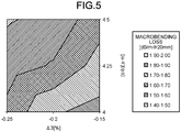
- FIG. 5 is a diagram illustrating a relationship among ⁇ 3, the trench width, and the macrobending loss.
- ⁇ 1 is set to 0.36% and ⁇ 2 is set to 0.02%.
- the macrobending loss is 1.5 to 2 dB/m.
- FIG. 5 even if ⁇ 1 is 0.36% and ⁇ 2 is 0.02%, by appropriately setting a combination of ⁇ 3 and (c - b), the macrobending loss becomes equal to or smaller than 1.5 dB/m.
- the present inventors confirmed that, with respect to the effective cutoff wavelength, the MFD, the zero-dispersion wavelength, and the dispersion slope, it is possible to realize characteristics that meet G.657 A2 standard or characteristics similar to the characteristics that meet G.657 A2 standard as follows: the effective cutoff wavelength is equal to or smaller than 1260 nm, the MFD at a wavelength of 1310 nm is equal to or larger than 8.6 ⁇ m and equal to or smaller than 9.5 ⁇ m, the zero-dispersion wavelength is equal to or larger than 1300 nm and equal to or smaller than 1324 nm, and the dispersion slope at the zero-dispersion wavelength is equal to or smaller than 0.092 ps/nm 2 /km under a condition in which ⁇ 1 is equal to or larger than 0.36% and equal to or smaller than 0.40%, ⁇ 2 is equal to or larger than -0.05% and equal to or smaller than 0.05%,
- is equal to or smaller than 0.25%
- b/a is equal to or larger than 1.8 and equal to or smaller than 3.6 and 2a is equal to or larger than 7.5 ⁇ m and equal to or smaller than 9.0 ⁇ m, but b/a and 2a are not limited to the ranges as described above.
- Table 2 lists values of the zero-dispersion wavelength, the dispersion slope, the MFD, the cutoff wavelength, and the macrobending loss among the optical characteristics, as results of simulation calculation performed with respect to No. 1 to No. 8. Meanwhile, in Table 2, standard values of G.657 A2 standard are listed as a standard. As can be understood from Table 1 and Table 2, it was confirmed that the result of the simulation calculation with respect to each of No. 1 to No. 8 met G.657 A2 standard.
- the optical fiber 10 according to the present embodiment can be manufactured by a well-known manufacturing method that includes a process of manufacturing an optical fiber preform and a process of manufacturing the optical fiber by heating and melting the optical fiber preform and performing drawing.
- the optical fiber preform includes portions that serve as the central core portion 11, the intermediate layer 12, the trench layer 13, and the cladding portion 14 of the optical fiber 10.
- the optical fiber preform can be manufactured by using a vapor phase axial deposition (VAD) method, a modified chemical vapor deposition (MCVD) method, a plasma chemical vapor deposition (PCVD) method, a sol-gel method or the like.
- VAD vapor phase axial deposition
- MCVD modified chemical vapor deposition
- PCVD plasma chemical vapor deposition
- the optical fiber preform by forming portions that serve as the central core portion 11, the intermediate layer 12, the trench layer 13, and a part of the cladding portion 14 of the optical fiber 10 by using the VAD method, and thereafter forming a glass layer that serves as remaining portions of the cladding portion 14 by using an outside vapor deposition (OVD) method, for example.
- OLED outside vapor deposition
- Table 3 lists measurement results of the optical characteristics of sample optical fibers that were manufactured by manufacturing optical fiber preforms by using the VAD method and the OVD method, and further performing drawing on the optical fiber preforms. Meanwhile, the sample optical fibers indicated by No. 1 and No. 2 were designed such that the combinations of the structural parameters indicated by No. 1 and No. 2 in Table 1 were obtained. As a result, it was confirmed that each of the sample optical fibers No. 1 and No. 2 met G.657 A2 standard with respect to the zero-dispersion wavelength, the dispersion slope, the MFD, the cutoff wavelength, and the macrobending loss, and the transmission loss was equal to or smaller than 0.2 dB/km, which was good.
- the present invention is not limited by the embodiment as described above.
- the present invention includes a configuration in which the structural elements as described above are appropriately combined. Further, additional advantages and modifications will readily occur to those skilled in the art. Therefore, the invention in its broader aspects is not limited to the embodiment as described above, and various modifications may be made.
- An optical fiber according to the present invention is preferably useful in the field of optical communication, such as data communication or telecommunication.
Landscapes
- Chemical & Material Sciences (AREA)
- Engineering & Computer Science (AREA)
- Physics & Mathematics (AREA)
- Materials Engineering (AREA)
- Life Sciences & Earth Sciences (AREA)
- General Life Sciences & Earth Sciences (AREA)
- Geochemistry & Mineralogy (AREA)
- Manufacturing & Machinery (AREA)
- Organic Chemistry (AREA)
- General Physics & Mathematics (AREA)
- Optics & Photonics (AREA)
- General Chemical & Material Sciences (AREA)
- Chemical Kinetics & Catalysis (AREA)
- Dispersion Chemistry (AREA)
- Manufacture, Treatment Of Glass Fibers (AREA)
- Optical Fibers, Optical Fiber Cores, And Optical Fiber Bundles (AREA)
Abstract
Description
- The present invention relates to an optical fiber and a method of manufacturing the optical fiber. Background
- Conventionally, to realize a single-mode optical fiber with low bending loss characteristics as defined by, for example, International Telecommunication Union - Telecommunication sector (ITU-T) G.657.A2 or the like, an optical fiber having a three-layer structure including a trench structure has been disclosed (
Patent Literatures 1 to 6). The optical fiber having the three-layer structure includes, for example, a central core portion, an intermediate layer that is formed on an outer periphery of the central core portion, a trench layer that is formed on an outer periphery of the intermediate layer, and a cladding portion that is formed on an outer periphery of the trench layer. -
- Patent Literature 1:
Japanese Patent No. 4833071 - Patent Literature 2:
Japanese Laid-open Patent Publication No. 2008-139887 - Patent Literature 3:
Japanese Laid-open Patent Publication No. 2010-181641 - Patent Literature 4:
Japanese Laid-open Patent Publication No. 2012-212115 - Patent Literature 5:
Japanese Laid-open Patent Publication No. 2013-242545 - Patent Literature 6:
Japanese Laid-open Patent Publication No. 2013-235261 - Optical characteristics of the optical fiber having the three-layer structure are designed by setting structural parameters, such as a relative refractive-index difference Δ1 of the central core portion, a relative refractive-index difference Δ2 of the intermediate layer, a relative refractive-index difference Δ3 of the trench layer, a
core diameter 2a of the central core portion, aninner diameter 2b of the trench layer (in other words, an outer diameter of the intermediate layer), and anouter diameter 2c. Meanwhile, in general, Δ3 is a negative value and Δ2 is a value smaller than Δ1. InPatent Literatures 1 to 6, various combinations of values of the structural parameters as described above are disclosed. - However, even in the disclosed optical fibers, there is room for improvement from the standpoint of manufacturability. For example, if Δ1 is designed to be high, a use amount of a dopant for improving a refractive index at the time of manufacturing increases. Similarly, if an absolute value of Δ3 is designed to be high or a width of the intermediate layer (a difference between the outer diameter and the inner diameter) is designed to be high, a use amount of a dopant for reducing a refractive index at the time of manufacturing increases. In contrast, particularly with regard to Δ1, if Δ1 is designed to be extremely low, it is necessary to precisely control the use amount of the dopant and an influence of disturbance increases, so that a manufacturing error may increase.
- The present invention has been conceived in view of the foregoing situations, and an object of the present invention is to provide an optical fiber that has low bending loss characteristics and high manufacturability and a method of manufacturing the optical fiber.
- To resolve the above problem and attain the object, an optical fiber according to an embodiment of the present invention includes: a central core portion; an intermediate layer that is formed on an outer periphery of the central core portion; a trench layer that is formed on an outer periphery of the intermediate layer; and a cladding portion that is formed on an outer periphery of the trench layer. Further, relationships Δ1>Δ2>Δ3 and 0>Δ3 are satisfied, where Δ1 is a relative refractive-index difference of the central core portion with respect to the cladding portion, Δ2 is a relative refractive-index difference of the intermediate layer with respect to the cladding portion, and Δ3 is a relative refractive-index difference of the trench layer with respect to the cladding portion, and (c - b) is smaller than 4.5 µm when Δ1 is equal to or larger than 0.36% and equal to or smaller than 0.40%, Δ2 is equal to or larger than -0.05% and equal to or smaller than 0.05%, Δ3 is equal to or smaller than 0.25%, Δ1 × |Δ3| is equal to or smaller than 0.08%2, an inner diameter of the trench layer is 2b, and an outer diameter of the trench layer is 2c.
- In the optical fiber according to an embodiment of the present invention, when a core dimeter of the central core portion is 2a and the inner dimeter of the trench layer is 2b, b/a is equal to or larger than 1.8 and equal to or smaller than 3.6.
- In the optical fiber according to an embodiment of the present invention, when a core diameter of the central core portion is 2a, 2a is equal to or larger than 7.5 µm and equal to or smaller than 9.0 µm.
- In the optical fiber according to an embodiment of the present invention, an effective cutoff wavelength is equal to or smaller than 1260 nm.
- In the optical fiber according to an embodiment of the present invention, a mode field diameter at a wavelength of 1310 nm is equal to or larger than 8.6 µm and equal to or smaller than 9.5 µm.
- In the optical fiber according to an embodiment of the present invention, a bending loss at a wavelength of 1550 nm when bending is made at a dimeter of 20 mm is equal to or smaller than 1.59 dB/m.
- In the optical fiber according to an embodiment of the present invention, a zero-dispersion wavelength is equal to or larger than 1300 nm and equal to or smaller than 1324 nm, and a dispersion slope at the zero-dispersion wavelength is equal to or smaller than 0.092 ps/nm2/km.
- A method of manufacturing the optical fiber according to an embodiment, the method includes: a step of manufacturing an optical fiber preform; and a step of manufacturing the optical fiber by heating and melting the optical fiber preform and performing drawing. Further, the step of manufacturing the optical fiber preform includes forming portions that serve as at least the central core portion, the intermediate layer, the trench layer, and a part of the cladding portion by using a vapor phase axial deposition method.
- According to the present invention, it is possible to realize an optical fiber that has low bending loss characteristics and high manufacturability.
-
-
FIG. 1 is a schematic cross-sectional view of an optical fiber according to a first embodiment. -
FIG. 2 is a diagram illustrating a refractive index profile of the optical fiber illustrated inFIG. 1 . -
FIG. 3 is a diagram illustrating a relationship between a trench width (c - b) and a macrobending loss. -
FIG. 4 is a diagram illustrating a relationship among Δ1, Δ2, and the macrobending loss. -
FIG. 5 is a diagram illustrating a relationship among Δ3, a trench width, and the macrobending loss. - Embodiments of the present invention will be described in detail below with reference to the drawings. The present invention is not limited by the embodiments described below. Further, in each of the drawings, the same or corresponding structural elements are appropriately denoted by the same reference symbols, and explanation of the structural elements will be omitted appropriately. Furthermore, in the present specification, a cutoff wavelength is an effective cutoff wavelength and indicates a cable cutoff wavelength that is defined by International Telecommunication Union - Telecommunication sector (ITU-T) G.650.1. Moreover, other terms that are not specifically defined in the present specification conform to definitions and measurement methods described in G.650.1 and G.650.2.
-
FIG. 1 is a schematic cross-sectional view of an optical fiber according to a first embodiment. Anoptical fiber 10 is made of silica based glass, and includes acentral core portion 11, anintermediate layer 12 that is formed on an outer periphery of thecentral core portion 11, atrench layer 13 that is formed on an outer periphery of theintermediate layer 12, and acladding portion 14 that is formed on an outer periphery of thetrench layer 13. -
FIG. 2 is a diagram illustrating a refractive index profile of theoptical fiber 10. A profile P11 is a refractive index profile of thecentral core portion 11 and is what called a center-core-portion type. A profile P12 is a refractive index profile of theintermediate layer 12. A profile P13 is a refractive index profile of thetrench layer 13. A profile P14 is a refractive index profile of thecladding portion 14. - Structural parameters of the
optical fiber 10 will be described. First, a core diameter of thecentral core portion 11 is 2a. Further, an outer diameter of theintermediate layer 12, that is, an inner diameter of thetrench layer 13 is 2b, and an outer diameter of thetrench layer 13 is 2c. Therefore, a width (trench width) of thetrench layer 13 is (c - b). Furthermore, a relative refractive-index difference of a maximum refractive index of thecentral core portion 11 with respect to a refractive index of thecladding portion 14 is Δ1. A relative refractive-index difference of a refractive index of theintermediate layer 12 with respect to the refractive index of thecladding portion 14 is Δ2. A relative refractive-index difference of a refractive index of thetrench layer 13 with respect to the refractive index of thecladding portion 14 is Δ3. As for Δ1, Δ2, and Δ3, Δ1>Δ2>Δ3 and 0>Δ3. In other words, Δ3 is a negative value, and therefore, thetrench layer 13 is able to improve the low bending loss characteristics of theoptical fiber 10. - Examples of constituent materials of the
optical fiber 10 will be described below. Thecentral core portion 11 is made of silica glass doped with a dopant, such as germanium (Ge), for adjusting the refractive index to improve the refractive index. Thetrench layer 13 is made of silica glass doped with a dopant, such as fluorine (F), for reducing the refractive index. Thecladding portion 14 is made of pure silica glass that does not contain a dopant, such as Ge or F, for adjusting the refractive index. Theintermediate layer 12 may be made of pure silica glass or may be doped with a certain amount of a dopant for adjusting the refractive index. However, the constituent materials and the dopants are not specifically limited as long as inequalities with respect to Δ1, Δ2, and Δ3 as described above are true. - In the
optical fiber 10, with regard to Δ1, Δ2, Δ3, and the trench width (c - b), Δ1 is equal to or larger than 0.36% and equal to or smaller than 0.40%, |Δ3| that is an absolute value of Δ3 is equal to or smaller than 0.25%, Δ1 × |Δ3| is equal to or smaller than 0.08%2, and the trench width (c - b) is smaller than 4.5 µm. Further, Δ2 is equal to or larger than -0.05% and equal to or smaller than 0.05%. In this manner, if Δ1 is equal to or larger than 0.36% and equal to or smaller than 0.40%, it is possible to reduce the use amount of the dopant for improving the refractive index at the time of manufacturing, it is possible to easily control the use amount of the dopant, and it is possible to relatively increase strength against disturbance, so that it is possible to reduce a manufacturing error. Furthermore, if |Δ3| is equal to or smaller than 0.25% and the trench width (c - b) is smaller than 4.5 µm, it is possible to reduce the use amount of the dopant for reducing the refractive index. Moreover, if the trench width (c - b) is smaller than 4.5 µm, it is possible to set the trench width (c - b) and a core radius of thecentral core portion 11 to approximately the same value, so that it is possible to easily adopt a manufacturing condition with reference to a manufacturing condition of the central core portion and it is possible to simplify manufacturing. Furthermore, if Δ1 × |Δ3| is equal to or smaller than 0.08%2, it is possible to effectively improve an effect of reduction of the use amounts of the dopants, an effect of simplicity of control, and an effect of reduction of the manufacturing error, so that it is possible to improve manufacturability of theoptical fiber 10. - As for |Δ3|, if |Δ3| is smaller than 0.25%, in particular, if |Δ3| is equal to or smaller than 0.20%, it is possible to further reduce the use amount of the dopant. Further, if |Δ3| is equal to or larger than 0.10%, it is possible to easily control the use amount of the dopant and it is possible to reduce the manufacturing error. As a result, it is possible to further improve the manufacturability of the
optical fiber 10. Meanwhile, if |Δ3| is equal to or larger than 0.10%, Δ1 × |Δ3| is equal to or larger than 0.034%2. Therefore, it is preferable that Δ1 × |Δ3| is equal to or larger than 0.034%2. - While details will be described later, as examples of preferable ranges of the other structural parameters, b/a is equal to or larger than 1.8 and equal to or smaller than 3.6, for example. Further, 2a is equal to or larger than 7.5 µm and equal to or smaller than 9.0 µm.
- By appropriately combining the values of the structural parameters as described above, the
optical fiber 10 can have a mode field diameter (MFD) equal to or larger than 8.6 µm and equal to or smaller than 9.5 µm at a wavelength of 1310 nm, as will be described in detail later. Further, theoptical fiber 10 can have an effective cutoff wavelength equal to or smaller than 1260 nm. Furthermore, theoptical fiber 10 can have a bending loss equal to or smaller than 1.59 dB/m at a wavelength of 1550 nm when bending is made at a diameter of 20 mm (hereinafter, the bending loss at a wavelength of 1550 nm when bending is made at the diameter of 20 mm may be simply referred to as a macrobending loss). Moreover, theoptical fiber 10 can have a zero-dispersion wavelength equal to or larger than 1300 nm and equal to or smaller than 1324 nm and have a dispersion slope equal to or smaller than 0.092 ps/nm2/km at the zero-dispersion wavelength. As a result, it is possible to provide theoptical fiber 10 that meets the standard defined by ITU-T G.652 (hereinafter, may be described as G.652 standard), for example. Furthermore, if the MFD is equal to or smaller than 9.2 µm, it is possible to provide theoptical fiber 10 that meets G.657A standard, in particular, G.657 A2 standard. Meanwhile, the value of 1.59 dB/m of the macrobending loss is a converted value of 0.1 dB/turn in G.657 A2 standard. Moreover, it may be possible to appropriately combine the values of the structural parameters such that the effective cutoff wavelength is equal to or smaller than 1530 nm, which meets G.654 standard. - Details will be described below using results of simulation calculation.
FIG. 4 is a diagram illustrating a relationship between the trench width (c - b) and the macrobending loss based on the simulation calculation. Diamond shapes represent data points, and a solid line represents a curved line of approximation of the data points by an exponential function. The data points represent calculation results that are obtained by setting Δ1, Δ2, Δ3, a, b, and c, which are the structural parameters, to various values such that |Δ3| is equal to or smaller than 0.25%. To reduce the macrobending loss while maintaining |Δ3| equal to or smaller than 0.25%, a larger trench width (c - b) is preferable. Therefore, to realize the trench width (c - b) smaller than 4.5 µm, it is necessary to appropriately set the structural parameters. -
FIG. 4 is a diagram illustrating a relationship among Δ1, Δ2, and the macrobending loss. InFIG. 4 , average values of the macrobending loss that are obtained under certain conditions in which each of Δ3, (c - b), and b/a is changed such that |Δ3| is equal to or smaller than 0.25%, Δ1 × |Δ3| is equal to or smaller than 0.08%2, (c - b) is smaller than 4.5 µm, and b/a is equal to or larger than 1.8 and equal to or smaller than 3.6 are illustrated. As can be understood fromFIG. 4 , under certain conditions in which Δ1 is equal to or larger than 0.36% and equal to or smaller than 0.40% and Δ2 is equal to or larger than - 0.05% and equal to or smaller than 0.05%, the macrobending loss is equal to or smaller than 1.59 dB/m in some cases. Meanwhile, in consideration of manufacturing variation, it is preferable to select a combination of the structural parameters such that the macrobending loss is equal to or smaller than 1.5 dB/m. - Meanwhile, as described above,
FIG. 4 illustrates the average values of the macrobending loss, and therefore, even with a combination of Δ1 and Δ2 with which the macrobending loss is not equal to or smaller than 1.5 dB/m inFIG. 4 , the macrobending loss may become equal to or smaller than 1.5 dB/m by optimization of the other structural parameters. - For example,
FIG. 5 is a diagram illustrating a relationship among Δ3, the trench width, and the macrobending loss. InFIG. 5 , Δ1 is set to 0.36% and Δ2 is set to 0.02%. InFIG. 4 , if Δ1 is 0.36% and Δ2 is 0.02%, the macrobending loss is 1.5 to 2 dB/m. However, as can be understoodFIG. 5 , even if Δ1 is 0.36% and Δ2 is 0.02%, by appropriately setting a combination of Δ3 and (c - b), the macrobending loss becomes equal to or smaller than 1.5 dB/m. - Further, through earnest examination, the present inventors confirmed that, with respect to the effective cutoff wavelength, the MFD, the zero-dispersion wavelength, and the dispersion slope, it is possible to realize characteristics that meet G.657 A2 standard or characteristics similar to the characteristics that meet G.657 A2 standard as follows: the effective cutoff wavelength is equal to or smaller than 1260 nm, the MFD at a wavelength of 1310 nm is equal to or larger than 8.6 µm and equal to or smaller than 9.5 µm, the zero-dispersion wavelength is equal to or larger than 1300 nm and equal to or smaller than 1324 nm, and the dispersion slope at the zero-dispersion wavelength is equal to or smaller than 0.092 ps/nm2/km under a condition in which Δ1 is equal to or larger than 0.36% and equal to or smaller than 0.40%, Δ2 is equal to or larger than -0.05% and equal to or smaller than 0.05%, |Δ3| is equal to or smaller than 0.25%, Δ1 × |Δ3| is equal to or smaller than 0.08%2, and (c - b) is smaller than 4.5 µm. Meanwhile, to realize the characteristics as described above, it is preferable that b/a is equal to or larger than 1.8 and equal to or smaller than 3.6 and 2a is equal to or larger than 7.5 µm and equal to or smaller than 9.0 µm, but b/a and 2a are not limited to the ranges as described above.
- Changes of the optical characteristics of the
optical fiber 10 when several structural parameters are changed will be described in detail below using results of simulation calculation. First, changes of the optical characteristics were calculated with respect to structural parameter combinations indicated by No. 1 to No. 8 in Table 1. In No. 1 to No. 8, Δ1 was changed in a range of 0.36% to 0.40%. Δ2 was changed in a range of -0.05% to 0.05%. |Δ3| was changed in a range of 0.2% to 0.22% and Δ1 × |Δ3| was changed in a range of 0.08%2 to 0.074%2. b/a was changed in a range of 1.8 to 3.6. 2a was changed in a range of 7.9 µm to 8.8 µm. (c - b) was changed in a range of 2.87 µm to 4.46 µm.Table 1 Δ1 Δ2 Δ3 Δ1×|Δ3| b/a 2a c-b [%] [%] [%] [%2] [µm] [µm] No. 1 0.39 0 -0.20 0.0780 3.0 8.2 4.10 No. 2 0.37 -0.05 -0.20 0.0740 3.0 8.7 4.35 No. 3 0.40 0 -0.20 0.0800 3.3 8.2 2.87 No. 4 0.36 -0.05 -0.22 0.0792 3.0 8.8 4.40 No. 5 0.40 0.02 -0.20 0.0800 3.0 7.9 4.15 No. 6 0.39 0 -0.20 0.0800 2.1 8.2 4.46 No. 7 0.39 0 -0.20 0.0780 1.8 8.4 4.18 No. 8 0.38 0 -0.20 0.0760 3.6 8.2 4.43 - Table 2 lists values of the zero-dispersion wavelength, the dispersion slope, the MFD, the cutoff wavelength, and the macrobending loss among the optical characteristics, as results of simulation calculation performed with respect to No. 1 to No. 8. Meanwhile, in Table 2, standard values of G.657 A2 standard are listed as a standard. As can be understood from Table 1 and Table 2, it was confirmed that the result of the simulation calculation with respect to each of No. 1 to No. 8 met G.657 A2 standard.
Table 2 Zero-dispersion wavelength Dispersion slope MFD Cutoff wavelength Macrobending loss [nm] [ps/nm2/km] @zero-dispersion wavelength [µm] @1310 nm [nm] @22 m [dB/m @20 mm] @1550 nm G.657 A2 standard 1300 - 1324 ≤ 0.092 8.6 - 9.2 ≤ 1260 ≤ 1.59 No. 1 Simulation 1312 0.088 8.68 1256 1.31 No. 2 Simulation 1301 0.090 8.71 1246 1.52 No. 3 Simulation 1312 0.087 8.62 1259 1.57 No. 4 Simulation 1300 0.090 8.82 1249 1.12 No. 5 Simulation 1320 0.087 8.63 1259 1.58 No. 6 Simulation 1306 0.091 8.64 1252 1.56 No. 7 Simulation 1300 0.092 8.60 1245 1.58 No. 8 Simulation 1316 0.086 8.71 1256 1.28 - Meanwhile, the
optical fiber 10 according to the present embodiment can be manufactured by a well-known manufacturing method that includes a process of manufacturing an optical fiber preform and a process of manufacturing the optical fiber by heating and melting the optical fiber preform and performing drawing. In this case, the optical fiber preform includes portions that serve as thecentral core portion 11, theintermediate layer 12, thetrench layer 13, and thecladding portion 14 of theoptical fiber 10. The optical fiber preform can be manufactured by using a vapor phase axial deposition (VAD) method, a modified chemical vapor deposition (MCVD) method, a plasma chemical vapor deposition (PCVD) method, a sol-gel method or the like. For example, it is possible to manufacture the optical fiber preform by forming portions that serve as thecentral core portion 11, theintermediate layer 12, thetrench layer 13, and a part of thecladding portion 14 of theoptical fiber 10 by using the VAD method, and thereafter forming a glass layer that serves as remaining portions of thecladding portion 14 by using an outside vapor deposition (OVD) method, for example. - Table 3 lists measurement results of the optical characteristics of sample optical fibers that were manufactured by manufacturing optical fiber preforms by using the VAD method and the OVD method, and further performing drawing on the optical fiber preforms. Meanwhile, the sample optical fibers indicated by No. 1 and No. 2 were designed such that the combinations of the structural parameters indicated by No. 1 and No. 2 in Table 1 were obtained. As a result, it was confirmed that each of the sample optical fibers No. 1 and No. 2 met G.657 A2 standard with respect to the zero-dispersion wavelength, the dispersion slope, the MFD, the cutoff wavelength, and the macrobending loss, and the transmission loss was equal to or smaller than 0.2 dB/km, which was good. Further, it was confirmed that, with regard to the zero-dispersion wavelength, the dispersion slope, the MFD, the cutoff wavelength, and the macrobending loss, the optical characteristics obtained through the simulation calculation indicated by No. 1 and No. 2 listed in Table 2 and the optical characteristics of the sample optical fibers No. 1 and No. 2 almost matched with each other.
Table 3 Zero-dispersion wavelength Dispersion slope MFD Cutoff wavelength Macrobending loss Transmission loss [nm] [ps/nm2/km] @zero-dispersion wavelength [µm] @1310 nm [nm] @22 m [dB/m @20 mm] @1550 nm [dB/km] @1550 nm G.657 A standard 1300 - 1324 ≤ 0.092 8.6 - 9.2 ≤ 1260 ≤ 1.59 No. 1 sample 1310 0.089 8.64 1251 1.18 0.199 No. 2 Sample 1303 0.091 8.73 1248 1.47 0.196 - Meanwhile, the present invention is not limited by the embodiment as described above. The present invention includes a configuration in which the structural elements as described above are appropriately combined. Further, additional advantages and modifications will readily occur to those skilled in the art. Therefore, the invention in its broader aspects is not limited to the embodiment as described above, and various modifications may be made.
- An optical fiber according to the present invention is preferably useful in the field of optical communication, such as data communication or telecommunication.
-
- 10
- optical fiber
- 11
- central core portion
- 12
- intermediate layer
- 13
- trench layer
- 14
- cladding portion
- P11, P12, P13, P14
- profile
Claims (8)
- An optical fiber comprising:a central core portion;an intermediate layer that is formed on an outer periphery of the central core portion;a trench layer that is formed on an outer periphery of the intermediate layer; anda cladding portion that is formed on an outer periphery of the trench layer, whereinrelationships Δ1>Δ2>Δ3 and 0>Δ3 are satisfied, where Δ1 is a relative refractive-index difference of the central core portion with respect to the cladding portion, Δ2 is a relative refractive-index difference of the intermediate layer with respect to the cladding portion, and Δ3 is a relative refractive-index difference of the trench layer with respect to the cladding portion, and(c - b) is smaller than 4.5 µm when Δ1 is equal to or larger than 0.36% and equal to or smaller than 0.40%, Δ2 is equal to or larger than -0.05% and equal to or smaller than 0.05%, |Δ3| is equal to or smaller than 0.25%, Δ1 × |Δ3| is equal to or smaller than 0.08%2, an inner diameter of the trench layer is 2b, and an outer diameter of the trench layer is 2c.
- The optical fiber according to claim 1, wherein when a core dimeter of the central core portion is 2a and the inner dimeter of the trench layer is 2b, b/a is equal to or larger than 1.8 and equal to or smaller than 3.6.
- The optical fiber according to claim 1 or 2, wherein when a core diameter of the central core portion is 2a, 2a is equal to or larger than 7.5 µm and equal to or smaller than 9.0 µm.
- The optical fiber according to any one of claims 1 to 3, wherein an effective cutoff wavelength is equal to or smaller than 1260 nm.
- The optical fiber according to any one of claims 1 to 4, wherein a mode field diameter at a wavelength of 1310 nm is equal to or larger than 8.6 µm and equal to or smaller than 9.5 µm.
- The optical fiber according to any one of claims 1 to 5, wherein a bending loss at a wavelength of 1550 nm when bending is made at a dimeter of 20 mm is equal to or smaller than 1.59 dB/m.
- The optical fiber according to any one of claims 1 to 6, whereina zero-dispersion wavelength is equal to or larger than 1300 nm and equal to or smaller than 1324 nm, anda dispersion slope at the zero-dispersion wavelength is equal to or smaller than 0.092 ps/nm2/km.
- A method of manufacturing the optical fiber according to any one of claims 1 to 7, the method comprising:a step of manufacturing an optical fiber preform; anda step of manufacturing the optical fiber by heating and melting the optical fiber preform and performing drawing, whereinthe step of manufacturing the optical fiber preform includes forming portions that serve as at least the central core portion, the intermediate layer, the trench layer, and a part of the cladding portion by using a vapor phase axial deposition method.
Applications Claiming Priority (2)
| Application Number | Priority Date | Filing Date | Title |
|---|---|---|---|
| JP2019020946A JP7019617B2 (en) | 2019-02-07 | 2019-02-07 | Optical fiber and manufacturing method of optical fiber |
| PCT/JP2020/002357 WO2020162209A1 (en) | 2019-02-07 | 2020-01-23 | Optical fiber and optical fiber manufacturing method |
Publications (3)
| Publication Number | Publication Date |
|---|---|
| EP3922612A1 true EP3922612A1 (en) | 2021-12-15 |
| EP3922612A4 EP3922612A4 (en) | 2022-10-19 |
| EP3922612B1 EP3922612B1 (en) | 2025-12-31 |
Family
ID=71947601
Family Applications (1)
| Application Number | Title | Priority Date | Filing Date |
|---|---|---|---|
| EP20752007.3A Active EP3922612B1 (en) | 2019-02-07 | 2020-01-23 | OPTICAL FIBER |
Country Status (4)
| Country | Link |
|---|---|
| US (1) | US11714229B2 (en) |
| EP (1) | EP3922612B1 (en) |
| JP (1) | JP7019617B2 (en) |
| WO (1) | WO2020162209A1 (en) |
Families Citing this family (6)
| Publication number | Priority date | Publication date | Assignee | Title |
|---|---|---|---|---|
| JP7608438B2 (en) * | 2020-03-27 | 2025-01-06 | 古河電気工業株式会社 | Optical Fiber |
| JP7757664B2 (en) | 2021-08-31 | 2025-10-22 | 住友電気工業株式会社 | optical fiber |
| EP4398008A4 (en) * | 2021-08-31 | 2024-12-25 | Sumitomo Electric Industries, Ltd. | Optical fiber |
| JP2024083756A (en) | 2022-12-12 | 2024-06-24 | 住友電気工業株式会社 | Optical Fiber |
| JP2024110717A (en) | 2023-02-03 | 2024-08-16 | 住友電気工業株式会社 | Optical Fiber |
| JP2024110698A (en) | 2023-02-03 | 2024-08-16 | 住友電気工業株式会社 | Optical Fiber |
Family Cites Families (18)
| Publication number | Priority date | Publication date | Assignee | Title |
|---|---|---|---|---|
| JPS4833071B1 (en) | 1969-01-24 | 1973-10-11 | ||
| EP1657575A4 (en) * | 2003-04-11 | 2008-03-19 | Fujikura Ltd | Optical fiber |
| JP4444177B2 (en) * | 2004-08-11 | 2010-03-31 | 古河電気工業株式会社 | Optical fiber, optical fiber tape and optical interconnection system |
| WO2006025231A1 (en) | 2004-08-30 | 2006-03-09 | Fujikura Ltd. | Single-mode optical fiber |
| US7620282B2 (en) | 2006-08-31 | 2009-11-17 | Corning Incorporated | Low bend loss single mode optical fiber |
| DK1930753T3 (en) | 2006-12-04 | 2015-03-30 | Draka Comteq Bv | Optical fiber having a high Brillouin threshold strength and low bending |
| US7844155B2 (en) | 2007-05-07 | 2010-11-30 | Corning Incorporated | Optical fiber containing alkali metal oxide |
| DK2581770T3 (en) | 2008-02-22 | 2014-06-30 | Sumitomo Electric Industries | Optical fiber and optical cable |
| JP5222752B2 (en) | 2009-02-05 | 2013-06-26 | 株式会社フジクラ | Optical fiber |
| KR20100091710A (en) * | 2009-02-11 | 2010-08-19 | 엘에스전선 주식회사 | Method for manufacturing optical fiber improvement of bending loss and optical fiber manufactured using the same |
| JP5142409B2 (en) * | 2010-03-26 | 2013-02-13 | 日本電信電話株式会社 | Single mode optical fiber |
| JP2012212115A (en) | 2011-03-23 | 2012-11-01 | Sumitomo Electric Ind Ltd | Optical fiber, optical fiber code and optical fiber cable |
| CN102156323B (en) * | 2011-05-05 | 2012-06-06 | 长飞光纤光缆有限公司 | Single mode fiber |
| KR20130116009A (en) * | 2012-04-12 | 2013-10-22 | 신에쓰 가가꾸 고교 가부시끼가이샤 | Optical fiber |
| KR101436723B1 (en) | 2012-04-26 | 2014-09-01 | 신에쓰 가가꾸 고교 가부시끼가이샤 | Optical fiber |
| JP6717194B2 (en) * | 2014-08-28 | 2020-07-01 | 住友電気工業株式会社 | Optical fiber and optical fiber transmission line |
| CN104316994A (en) * | 2014-10-29 | 2015-01-28 | 长飞光纤光缆股份有限公司 | Low-attenuation bending insensitive single mode fiber |
| CA3070060A1 (en) * | 2017-01-27 | 2018-08-02 | Sterlite Technologies Limited | Optical fiber draw assembly and fabricated optical fiber thereof |
-
2019
- 2019-02-07 JP JP2019020946A patent/JP7019617B2/en active Active
-
2020
- 2020-01-23 EP EP20752007.3A patent/EP3922612B1/en active Active
- 2020-01-23 WO PCT/JP2020/002357 patent/WO2020162209A1/en not_active Ceased
-
2021
- 2021-08-04 US US17/393,993 patent/US11714229B2/en active Active
Also Published As
| Publication number | Publication date |
|---|---|
| US11714229B2 (en) | 2023-08-01 |
| US20210364692A1 (en) | 2021-11-25 |
| WO2020162209A1 (en) | 2020-08-13 |
| EP3922612A4 (en) | 2022-10-19 |
| EP3922612B1 (en) | 2025-12-31 |
| JP7019617B2 (en) | 2022-02-15 |
| JP2020129037A (en) | 2020-08-27 |
Similar Documents
| Publication | Publication Date | Title |
|---|---|---|
| EP3922612B1 (en) | OPTICAL FIBER | |
| EP3715923B1 (en) | Single-mode optical fiber with ultralow loss and large effective area and manufacturing method therefor | |
| US10571628B2 (en) | Low loss optical fiber with core codoped with two or more halogens | |
| EP1739063A2 (en) | Low loss optical fiber designs and methods for their manufacture | |
| CN111512200B (en) | Bend loss insensitive single mode optical fiber with shallow trench and corresponding optical system | |
| EP4318061A1 (en) | Optical fiber | |
| EP3764133A1 (en) | Optical fiber | |
| EP3657223B1 (en) | Optical fiber and method for producing same | |
| CN111801609B (en) | Optical fiber | |
| EP4123350B1 (en) | Optical fiber | |
| EP4403968A1 (en) | Optical fiber | |
| EP3896038B1 (en) | Optical fiber | |
| US20250284049A1 (en) | Optical fiber | |
| EP3754393A1 (en) | Optical fiber | |
| EP3932879A1 (en) | Optical fiber and method for manufacturing optical fiber | |
| US20230244027A1 (en) | Optical fiber | |
| EP4254027A1 (en) | Optical fibers with improved bend performance and manufacturing method thereof | |
| EP4130819A1 (en) | Optical fiber | |
| EP4321910A1 (en) | Optical fiber | |
| EP4535051A1 (en) | Optical fiber | |
| JP2001290041A (en) | Dispersion compensating optical fiber |
Legal Events
| Date | Code | Title | Description |
|---|---|---|---|
| STAA | Information on the status of an ep patent application or granted ep patent |
Free format text: STATUS: THE INTERNATIONAL PUBLICATION HAS BEEN MADE |
|
| PUAI | Public reference made under article 153(3) epc to a published international application that has entered the european phase |
Free format text: ORIGINAL CODE: 0009012 |
|
| STAA | Information on the status of an ep patent application or granted ep patent |
Free format text: STATUS: REQUEST FOR EXAMINATION WAS MADE |
|
| 17P | Request for examination filed |
Effective date: 20210803 |
|
| AK | Designated contracting states |
Kind code of ref document: A1 Designated state(s): AL AT BE BG CH CY CZ DE DK EE ES FI FR GB GR HR HU IE IS IT LI LT LU LV MC MK MT NL NO PL PT RO RS SE SI SK SM TR |
|
| DAV | Request for validation of the european patent (deleted) | ||
| DAX | Request for extension of the european patent (deleted) | ||
| REG | Reference to a national code |
Free format text: PREVIOUS MAIN CLASS: C03B0037012000 Ref country code: DE Ref legal event code: R079 Ref document number: 602020064770 Country of ref document: DE Free format text: PREVIOUS MAIN CLASS: C03B0037012000 Ipc: C03B0037027000 |
|
| A4 | Supplementary search report drawn up and despatched |
Effective date: 20220920 |
|
| RIC1 | Information provided on ipc code assigned before grant |
Ipc: C03B 37/014 20060101ALI20220914BHEP Ipc: G02B 6/036 20060101ALI20220914BHEP Ipc: C03B 37/027 20060101AFI20220914BHEP |
|
| STAA | Information on the status of an ep patent application or granted ep patent |
Free format text: STATUS: EXAMINATION IS IN PROGRESS |
|
| 17Q | First examination report despatched |
Effective date: 20240715 |
|
| GRAP | Despatch of communication of intention to grant a patent |
Free format text: ORIGINAL CODE: EPIDOSNIGR1 |
|
| STAA | Information on the status of an ep patent application or granted ep patent |
Free format text: STATUS: GRANT OF PATENT IS INTENDED |
|
| INTG | Intention to grant announced |
Effective date: 20250820 |
|
| GRAS | Grant fee paid |
Free format text: ORIGINAL CODE: EPIDOSNIGR3 |
|
| GRAA | (expected) grant |
Free format text: ORIGINAL CODE: 0009210 |
|
| STAA | Information on the status of an ep patent application or granted ep patent |
Free format text: STATUS: THE PATENT HAS BEEN GRANTED |
|
| AK | Designated contracting states |
Kind code of ref document: B1 Designated state(s): AL AT BE BG CH CY CZ DE DK EE ES FI FR GB GR HR HU IE IS IT LI LT LU LV MC MK MT NL NO PL PT RO RS SE SI SK SM TR |
|
| P01 | Opt-out of the competence of the unified patent court (upc) registered |
Free format text: CASE NUMBER: UPC_APP_0014484_3922612/2025 Effective date: 20251124 |
|
| REG | Reference to a national code |
Ref country code: CH Ref legal event code: F10 Free format text: ST27 STATUS EVENT CODE: U-0-0-F10-F00 (AS PROVIDED BY THE NATIONAL OFFICE) Effective date: 20251231 Ref country code: GB Ref legal event code: FG4D |
|
| REG | Reference to a national code |
Ref country code: DE Ref legal event code: R096 Ref document number: 602020064770 Country of ref document: DE |
|
| REG | Reference to a national code |
Ref country code: IE Ref legal event code: FG4D |
|
| REG | Reference to a national code |
Ref country code: LT Ref legal event code: MG9D |
|
| PG25 | Lapsed in a contracting state [announced via postgrant information from national office to epo] |
Ref country code: NO Free format text: LAPSE BECAUSE OF FAILURE TO SUBMIT A TRANSLATION OF THE DESCRIPTION OR TO PAY THE FEE WITHIN THE PRESCRIBED TIME-LIMIT Effective date: 20260331 |
|
| PGFP | Annual fee paid to national office [announced via postgrant information from national office to epo] |
Ref country code: DE Payment date: 20260121 Year of fee payment: 7 |
|
| PG25 | Lapsed in a contracting state [announced via postgrant information from national office to epo] |
Ref country code: HR Free format text: LAPSE BECAUSE OF FAILURE TO SUBMIT A TRANSLATION OF THE DESCRIPTION OR TO PAY THE FEE WITHIN THE PRESCRIBED TIME-LIMIT Effective date: 20251231 Ref country code: FI Free format text: LAPSE BECAUSE OF FAILURE TO SUBMIT A TRANSLATION OF THE DESCRIPTION OR TO PAY THE FEE WITHIN THE PRESCRIBED TIME-LIMIT Effective date: 20251231 |
|
| PG25 | Lapsed in a contracting state [announced via postgrant information from national office to epo] |
Ref country code: RS Free format text: LAPSE BECAUSE OF FAILURE TO SUBMIT A TRANSLATION OF THE DESCRIPTION OR TO PAY THE FEE WITHIN THE PRESCRIBED TIME-LIMIT Effective date: 20260331 |
|
| PGFP | Annual fee paid to national office [announced via postgrant information from national office to epo] |
Ref country code: FR Payment date: 20260219 Year of fee payment: 7 |
|
| PG25 | Lapsed in a contracting state [announced via postgrant information from national office to epo] |
Ref country code: LV Free format text: LAPSE BECAUSE OF FAILURE TO SUBMIT A TRANSLATION OF THE DESCRIPTION OR TO PAY THE FEE WITHIN THE PRESCRIBED TIME-LIMIT Effective date: 20251231 |
|
| PG25 | Lapsed in a contracting state [announced via postgrant information from national office to epo] |
Ref country code: BG Free format text: LAPSE BECAUSE OF FAILURE TO SUBMIT A TRANSLATION OF THE DESCRIPTION OR TO PAY THE FEE WITHIN THE PRESCRIBED TIME-LIMIT Effective date: 20251231 |
|
| REG | Reference to a national code |
Ref country code: NL Ref legal event code: MP Effective date: 20251231 |
|
| REG | Reference to a national code |
Ref country code: AT Ref legal event code: MK05 Ref document number: 1873132 Country of ref document: AT Kind code of ref document: T Effective date: 20251231 |
|
| PG25 | Lapsed in a contracting state [announced via postgrant information from national office to epo] |
Ref country code: NL Free format text: LAPSE BECAUSE OF FAILURE TO SUBMIT A TRANSLATION OF THE DESCRIPTION OR TO PAY THE FEE WITHIN THE PRESCRIBED TIME-LIMIT Effective date: 20251231 |
|
| PG25 | Lapsed in a contracting state [announced via postgrant information from national office to epo] |
Ref country code: LT Free format text: LAPSE BECAUSE OF FAILURE TO SUBMIT A TRANSLATION OF THE DESCRIPTION OR TO PAY THE FEE WITHIN THE PRESCRIBED TIME-LIMIT Effective date: 20251231 |
|
| PG25 | Lapsed in a contracting state [announced via postgrant information from national office to epo] |
Ref country code: SM Free format text: LAPSE BECAUSE OF FAILURE TO SUBMIT A TRANSLATION OF THE DESCRIPTION OR TO PAY THE FEE WITHIN THE PRESCRIBED TIME-LIMIT Effective date: 20251231 |
|
| PG25 | Lapsed in a contracting state [announced via postgrant information from national office to epo] |
Ref country code: ES Free format text: LAPSE BECAUSE OF FAILURE TO SUBMIT A TRANSLATION OF THE DESCRIPTION OR TO PAY THE FEE WITHIN THE PRESCRIBED TIME-LIMIT Effective date: 20251231 |
|
| PG25 | Lapsed in a contracting state [announced via postgrant information from national office to epo] |
Ref country code: PL Free format text: LAPSE BECAUSE OF FAILURE TO SUBMIT A TRANSLATION OF THE DESCRIPTION OR TO PAY THE FEE WITHIN THE PRESCRIBED TIME-LIMIT Effective date: 20251231 |
|
| PG25 | Lapsed in a contracting state [announced via postgrant information from national office to epo] |
Ref country code: IT Free format text: LAPSE BECAUSE OF FAILURE TO SUBMIT A TRANSLATION OF THE DESCRIPTION OR TO PAY THE FEE WITHIN THE PRESCRIBED TIME-LIMIT Effective date: 20251231 |
|
| PG25 | Lapsed in a contracting state [announced via postgrant information from national office to epo] |
Ref country code: AT Free format text: LAPSE BECAUSE OF FAILURE TO SUBMIT A TRANSLATION OF THE DESCRIPTION OR TO PAY THE FEE WITHIN THE PRESCRIBED TIME-LIMIT Effective date: 20251231 |
|
| PG25 | Lapsed in a contracting state [announced via postgrant information from national office to epo] |
Ref country code: EE Free format text: LAPSE BECAUSE OF FAILURE TO SUBMIT A TRANSLATION OF THE DESCRIPTION OR TO PAY THE FEE WITHIN THE PRESCRIBED TIME-LIMIT Effective date: 20251231 |
|
| PG25 | Lapsed in a contracting state [announced via postgrant information from national office to epo] |
Ref country code: IS Free format text: LAPSE BECAUSE OF FAILURE TO SUBMIT A TRANSLATION OF THE DESCRIPTION OR TO PAY THE FEE WITHIN THE PRESCRIBED TIME-LIMIT Effective date: 20260430 Ref country code: PT Free format text: LAPSE BECAUSE OF FAILURE TO SUBMIT A TRANSLATION OF THE DESCRIPTION OR TO PAY THE FEE WITHIN THE PRESCRIBED TIME-LIMIT Effective date: 20260430 |
|
| PG25 | Lapsed in a contracting state [announced via postgrant information from national office to epo] |
Ref country code: CZ Free format text: LAPSE BECAUSE OF FAILURE TO SUBMIT A TRANSLATION OF THE DESCRIPTION OR TO PAY THE FEE WITHIN THE PRESCRIBED TIME-LIMIT Effective date: 20251231 |
|
| PG25 | Lapsed in a contracting state [announced via postgrant information from national office to epo] |
Ref country code: SK Free format text: LAPSE BECAUSE OF FAILURE TO SUBMIT A TRANSLATION OF THE DESCRIPTION OR TO PAY THE FEE WITHIN THE PRESCRIBED TIME-LIMIT Effective date: 20251231 |
|
| PG25 | Lapsed in a contracting state [announced via postgrant information from national office to epo] |
Ref country code: SE Free format text: LAPSE BECAUSE OF FAILURE TO SUBMIT A TRANSLATION OF THE DESCRIPTION OR TO PAY THE FEE WITHIN THE PRESCRIBED TIME-LIMIT Effective date: 20251231 |