EP3922558A2 - Self-disinfecting portable physical partitions for aircraft interiors - Google Patents
Self-disinfecting portable physical partitions for aircraft interiors Download PDFInfo
- Publication number
- EP3922558A2 EP3922558A2 EP21179049.8A EP21179049A EP3922558A2 EP 3922558 A2 EP3922558 A2 EP 3922558A2 EP 21179049 A EP21179049 A EP 21179049A EP 3922558 A2 EP3922558 A2 EP 3922558A2
- Authority
- EP
- European Patent Office
- Prior art keywords
- disinfecting
- self
- housing
- flexible screen
- partition system
- Prior art date
- Legal status (The legal status is an assumption and is not a legal conclusion. Google has not performed a legal analysis and makes no representation as to the accuracy of the status listed.)
- Granted
Links
Images






Classifications
-
- B—PERFORMING OPERATIONS; TRANSPORTING
- B64—AIRCRAFT; AVIATION; COSMONAUTICS
- B64D—EQUIPMENT FOR FITTING IN OR TO AIRCRAFT; FLIGHT SUITS; PARACHUTES; ARRANGEMENT OR MOUNTING OF POWER PLANTS OR PROPULSION TRANSMISSIONS IN AIRCRAFT
- B64D11/00—Passenger or crew accommodation; Flight-deck installations not otherwise provided for
- B64D11/06—Arrangements of seats, or adaptations or details specially adapted for aircraft seats
- B64D11/0606—Arrangements of seats, or adaptations or details specially adapted for aircraft seats with privacy shells, screens, separators or the like
-
- A—HUMAN NECESSITIES
- A61—MEDICAL OR VETERINARY SCIENCE; HYGIENE
- A61L—METHODS OR APPARATUS FOR STERILISING MATERIALS OR OBJECTS IN GENERAL; DISINFECTION, STERILISATION OR DEODORISATION OF AIR; CHEMICAL ASPECTS OF BANDAGES, DRESSINGS, ABSORBENT PADS OR SURGICAL ARTICLES; MATERIALS FOR BANDAGES, DRESSINGS, ABSORBENT PADS OR SURGICAL ARTICLES
- A61L2/00—Disinfection or sterilisation of materials or objects, in general; Accessories therefor
- A61L2/02—Disinfection or sterilisation of materials or objects, in general; Accessories therefor using physical processes
- A61L2/08—Radiation
- A61L2/082—X-rays
-
- A—HUMAN NECESSITIES
- A61—MEDICAL OR VETERINARY SCIENCE; HYGIENE
- A61L—METHODS OR APPARATUS FOR STERILISING MATERIALS OR OBJECTS IN GENERAL; DISINFECTION, STERILISATION OR DEODORISATION OF AIR; CHEMICAL ASPECTS OF BANDAGES, DRESSINGS, ABSORBENT PADS OR SURGICAL ARTICLES; MATERIALS FOR BANDAGES, DRESSINGS, ABSORBENT PADS OR SURGICAL ARTICLES
- A61L2/00—Disinfection or sterilisation of materials or objects, in general; Accessories therefor
- A61L2/02—Disinfection or sterilisation of materials or objects, in general; Accessories therefor using physical processes
- A61L2/08—Radiation
- A61L2/10—Ultraviolet [UV] radiation
-
- B—PERFORMING OPERATIONS; TRANSPORTING
- B60—VEHICLES IN GENERAL
- B60N—SEATS SPECIALLY ADAPTED FOR VEHICLES; VEHICLE PASSENGER ACCOMMODATION NOT OTHERWISE PROVIDED FOR
- B60N2/00—Seats specially adapted for vehicles; Arrangement or mounting of seats in vehicles
- B60N2/90—Details or parts not otherwise provided for
- B60N2/91—Panels between front seats
-
- A—HUMAN NECESSITIES
- A61—MEDICAL OR VETERINARY SCIENCE; HYGIENE
- A61L—METHODS OR APPARATUS FOR STERILISING MATERIALS OR OBJECTS IN GENERAL; DISINFECTION, STERILISATION OR DEODORISATION OF AIR; CHEMICAL ASPECTS OF BANDAGES, DRESSINGS, ABSORBENT PADS OR SURGICAL ARTICLES; MATERIALS FOR BANDAGES, DRESSINGS, ABSORBENT PADS OR SURGICAL ARTICLES
- A61L2202/00—Aspects relating to methods or apparatus for disinfecting or sterilising materials or objects
- A61L2202/10—Apparatus features
- A61L2202/12—Apparatus for isolating biocidal substances from the environment
- A61L2202/122—Chambers for sterilisation
-
- A—HUMAN NECESSITIES
- A61—MEDICAL OR VETERINARY SCIENCE; HYGIENE
- A61L—METHODS OR APPARATUS FOR STERILISING MATERIALS OR OBJECTS IN GENERAL; DISINFECTION, STERILISATION OR DEODORISATION OF AIR; CHEMICAL ASPECTS OF BANDAGES, DRESSINGS, ABSORBENT PADS OR SURGICAL ARTICLES; MATERIALS FOR BANDAGES, DRESSINGS, ABSORBENT PADS OR SURGICAL ARTICLES
- A61L2202/00—Aspects relating to methods or apparatus for disinfecting or sterilising materials or objects
- A61L2202/10—Apparatus features
- A61L2202/14—Means for controlling sterilisation processes, data processing, presentation and storage means, e.g. sensors, controllers, programs
-
- A—HUMAN NECESSITIES
- A61—MEDICAL OR VETERINARY SCIENCE; HYGIENE
- A61L—METHODS OR APPARATUS FOR STERILISING MATERIALS OR OBJECTS IN GENERAL; DISINFECTION, STERILISATION OR DEODORISATION OF AIR; CHEMICAL ASPECTS OF BANDAGES, DRESSINGS, ABSORBENT PADS OR SURGICAL ARTICLES; MATERIALS FOR BANDAGES, DRESSINGS, ABSORBENT PADS OR SURGICAL ARTICLES
- A61L2202/00—Aspects relating to methods or apparatus for disinfecting or sterilising materials or objects
- A61L2202/10—Apparatus features
- A61L2202/16—Mobile applications, e.g. portable devices, trailers, devices mounted on vehicles
Definitions
- microbes e.g., virus, bacteria, or fungus
- the transfer of microbes has become a greater concern over time due to recent pandemics.
- the commercial aircraft industry is particularly concerned about person-to-person transfer of microbes, as flight in an aircraft often necessitates congregating diverse groups of people in a constricted area for long periods of time.
- barriers may be implemented between passengers to block or reduce microbial transfer.
- these barriers need to be disinfected often.
- the disinfection of these barriers often includes manual spraying and wiping surfaces with disinfection solution, a method that is time consuming, and may use toxic materials that may degrade aircraft interior surfaces over time. Accordingly, it is desirable to provide a system that avoids the shortcomings of conventional approaches.
- the self-disinfecting partition system includes a housing.
- the housing includes an attachment element configured to attach the housing to a first surface.
- the housing further includes an opening.
- the self-disinfecting partition system further includes a flexible screen configured to restrict a transmission of microbes, and further configured to deploy from a retracted position within the housing to a deployed position at least partially outside of the opening.
- the self-disinfecting partition system further includes a first arm mechanically coupled to an interior of the housing and configured to deploy from a first stored position within the housing to a first extended position at least partially outside of the opening.
- the first arm includes a first screen attachment assembly coupled to a first end of the one arm, wherein the first end of the one arm is configured to attach to a first border of the flexible screen.
- the self-disinfecting partition system further includes a retraction assembly configured to retract the flexible screen from the deployed position to the retracted position.
- the retraction assembly includes a reel configured to wind the flexible screen.
- the retraction assembly further includes one or more guide rollers configured to guide the flexible screen onto the reel.
- the self-disinfecting partition system further includes an electromagnetic energy source disposed within the housing configured to emit electromagnetic energy onto the flexible screen, wherein the electromagnetic energy is configured to disinfect the flexible screen.
- the self-disinfecting partition system further includes a second arm mechanically coupled to the housing and configured to deploy from a second stored position within the housing to a second extended position at least partially outside of the housing.
- the second arm includes a second screen attachment assembly coupled to a first end of the second arm, wherein the first end of the second arm is configured to attach to the first border of the flexible screen.
- the first arm is further configured to telescope.
- the first screen attachment assembly is in constant contact with the first border of the flexible screen as the flexible screen is deployed from the retracted position to the deployed position.
- the self-disinfecting partition system further includes a connecting rod attached to the first screen attachment assembly and the second attachment assembly, wherein the connecting rod is coupled to the first border of the flexible screen.
- the self-disinfecting partition system further includes at least one door coupled to the housing configured to cover the opening when the first arm is retracted inside the housing.
- the first arm is further configured to rotate from a stored position to the extended position via a first joint.
- the first screen attachment assembly further includes a first screen clamp coupled to the flexible screen and slidably coupled to the first arm.
- the retraction assembly further comprises a rotary actuator configured to rotate the reel.
- the self-disinfecting partition system further comprises an electrical scheme configured to power at least one of the electromagnetic energy source or the retraction assembly.
- the self-disinfecting partition system further comprises a user interface communicatively coupled to the electrical scheme.
- the self-disinfecting partition system includes a housing. In one or more embodiments, the self-disinfecting partition system further includes an attachment element configured to couple the self-disinfecting partition system to the seat. In one or more embodiments, the attachment element includes one or more apertures configured to accept one or more supports. In one or more embodiments, the self-disinfecting partition system further includes an extension assembly coupled to the housing and the attachment element. In one or more embodiments, the extension assembly includes the one or more supports coupled to the housing and configured to slide within the one or more apertures, wherein sliding of the one or more supports within the one or more apertures adjusts a distance of the housing from the seat.
- the extension assembly further includes a lock coupled to the attachment element and operationally coupled to the one or more supports and the one or more apertures; wherein the lock is configured upon activation to restrict a movement of the one or more supports relative to the one or more apertures.
- the self-disinfecting partition system further includes a flexible screen configured to block a transmission of microbes, and further configured to deploy from a retracted position within the housing to a deployed position.
- the self-disinfecting partition system further includes one or more electromagnetic energy sources disposed within the housing configured to emit electromagnetic energy onto the flexible screen when the flexible screen is configured in the retracted position, wherein the electromagnetic energy is configured to disinfect the flexible screen.
- the flexible screen is configured to retract via an accordion fold.
- the self-disinfecting partition system further includes an electrical scheme configured to power at least one of the electromagnetic energy source.
- the self-disinfecting partition system further includes a user interface communicatively coupled to the electrical scheme.
- a letter following a reference numeral is intended to reference an embodiment of the feature or element that may be similar, but not necessarily identical, to a previously described element or feature bearing the same reference numeral (e.g., 1, 1a, 1b).
- reference numeral e.g. 1, 1a, 1b
- Such shorthand notations are used for purposes of convenience only and should not be construed to limit the disclosure in any way unless expressly stated to the contrary.
- any reference to “one embodiment” or “some embodiments” means that a particular element, feature, structure, or characteristic described in connection with the embodiment is included in at least one embodiment disclosed herein.
- the appearances of the phrase “in some embodiments” in various places in the specification are not necessarily all referring to the same embodiment, and embodiments may include one or more of the features expressly described or inherently present herein, or any combination of sub-combination of two or more such features, along with any other features which may not necessarily be expressly described or inherently present in the instant disclosure.
- a self-disinfecting partition system is disclosed.
- the self-disinfecting partition system may be used to prevent communication of microbes between people, such as passengers on an aircraft, via a deployable partition screen that retracts from a housing.
- the partition screen When not in use, the partition screen may be retracted into the housing.
- Electromagnetic energy (e.g., ultraviolet light) scanners within the housing scan the partition screen while the partition screen is retracting and/or retracted, sterilizing microbes that have attached themselves to the screen.
- FIG. 1A is a perspective view of a self-disinfecting partition system 100 configured in a retracted position, in accordance with one or more embodiments of the disclosure.
- the self-disinfecting partition system 100 is configured to configured to block, or otherwise hinder, the transmission of pathogens (e.g., bacteria, viruses, or fungi) from one person to another.
- pathogens e.g., bacteria, viruses, or fungi
- the self-disinfecting partition system 100 may be configured for use in a wide variety of environments including but not limited to vehicles (e.g., aircraft, buses, trains, taxis) medical reception areas, ticket counters, payment terminals (e.g., at supermarkets), movie theaters and other public venues.
- the self-disinfecting partition system 100 may be configured for use on a passenger seat of a commercial aircraft.
- the self-disinfecting partition system 100 includes a housing 104 that houses one or more components of the self-disinfecting partition system 100.
- the housing 104 may be configured of any shape of form including but not limited to a rectangular prism.
- self-disinfecting partition system 100 further includes a flexible screen 106 (e.g., mostly hidden from view in FIG. 1A ).
- the flexible screen 106 is stored in a retracted position within the housing 104 when not in use (e.g., as in FIG. 1A ), then subsequently extended into a deployed position when in (e.g., as in FIG. 1B ).
- the flexible screen 106 may be of any size of shape, and may be constructed of any material included but limited to cloth, fiber, nylon, or plastic.
- the self-disinfecting partition system 100 further includes a first screen attachment assembly 108a and/or a second screen attachment assembly 108b configured to attach to a first border of the flexible screen 106.
- the first border of the flexible screen 106 may be considered a strip of a relatively small width (e.g., approximately 2 cm) of the leading edge of the flexible screen 106.
- the first screen attachment assembly 108a and/or a second screen attachment assembly 108b may use any type of technology to attach to the first border of the flexible screen including but not limited the use of clamps, adhesives, and crimping.
- the first screen attachment assembly 108a and/or the second screen attachment assembly 108b further includes a connecting rod 112 coupled to the first screen attachment assembly 108a and the second screen attachment assembly 108b (e.g., the connecting rod provides the major attachment point of the flexible screen 106 and acts as an extension of the first screen attachment assembly 108a and/or the second screen attachment assembly 108b.)
- the connecting rod 112 may be attached to the first screen attachment assembly 108a and/or the second screen attachment assembly 108b using any technology including but not limited to a bushing.
- FIG. 1B is a perspective view of a self-disinfecting partition system 100 with the flexible screen 106 extended in a deployed configuration, in accordance with one or more embodiments of the disclosure.
- the extension of the flexible screen may be accomplished by manually pulling upwards on the connecting rod.
- the extension of the flexible screen is accomplished through a rotary actuator disposed within the housing 104 (e.g., electrically powered, or powered by a spring).
- the extension of the flexible screen 106 from the housing 104 exposes a first arm 120a and a second arm 120b that rise from the housing 104 to support the flexible screen.
- a first end of the first arm 120 may be coupled to the first screen attachment assembly 108a, whereas a second end 122b of the second arm may be attached to the second screen attachment assembly 108b.
- the first arm 120a and/or second arm 120b may be configured with telescopic subunits 124a-f, allowing the first arm 120a and/or second arm 120b to straightforwardly extend and/or retract into the housing 104.
- the screen attachment assemblies 108a, 108b e.g., including the connecting rod 112 are in constant contact with the first border of the flexible screen 106 as the flexible screen 106 is deployed from the retracted position to the deployed position.
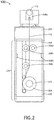
- FIG. 2 is a side cutaway view of the self-disinfecting partition system 100 configured in a retracted position, in accordance with one or more embodiments of the disclosure.
- the self-disinfecting partition system 100 further includes a retraction assembly 200 configured to guide and/or power the flexible screen 106 into the housing 104.
- the retraction assembly 200 may include a reel 204 attached to an end border of the flexible screen 106 (e.g., the border of the flexible screen 116 opposite of the first border).
- the reel 204 may actuate via a rotary actuator 212 (e.g., a loaded spring or electric motor), effectively winding the flexible screen 106 upon the reel 204.
- a rotary actuator 212 e.g., a loaded spring or electric motor
- the retraction assembly further includes one or more guide rollers 208a-c configured to guide the flexible screen 106 onto the reel 204.
- a pair of guide rollers 208a, 208b may be closely positioned on opposite surfaces of the flexible screen 106, acting to guide the flexible screen 106 toward the reel 204 and/or provide facilitate a tension upon the flexible screen 106 so that the flexible screen 106 may be properly wound.
- the housing further includes one or more electromagnetic energy sources 216 configured to emit electromagnetic energy onto the flexible screen 106.
- the one or more electromagnetic energy sources 216 may emit any type of electromagnetic energy that disinfects/sterilized the flexible screen 106 including but not limited to ultraviolet light and X-rays.
- the electromagnetic energy sources 216 may include any type or form of ultraviolet light-emitting technology including but not limited to light-emitting diodes (LED), mercury vapor lights, shortwave fluorescent lamp tubes, "black light” incandescent lamps, gas-discharge lamps, and lasers.
- one or more electromagnetic energy sources 216 may be configured as an ultraviolet-emitting LED.
- the self-disinfecting partition system 100 may use any number, size, type, or configuration of the one or more electromagnetic energy sources 216.
- the housing may include two lines of ultraviolet-emitting LEDs that run along opposing interior sides of the housing 104.
- the one or more electromagnetic energy sources 216 emit electromagnetic energy only while the flexible screen is being retracted or deployed. In some embodiments, the electromagnetic energy sources 2016 emit electromagnetic energy while flexible screen has been fully deployed (e.g., for a set amount of time).
- the housing 104 may include one or more attachment elements 220 configured to attach the housing 104 to a surface (e.g., the surface of a chair, armrest, setback, headrest, overhead bin, or side console).
- the one or more attachment elements 220 may including any type of attachment technology including but limited to adhesives, bolts, screws, hook-and-loop, suction or an interference fit.
- the housing further includes a cap 205.
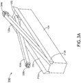
- FIG. 3A is a perspective view of a self-disinfecting partition system 300 configured in a partially deployed position, in accordance with one or more embodiments of the disclosure.
- the self-disinfecting partition system 300 may include one or more, or all, components of the self-disinfecting partition system 100, and vice versa.
- the first arm 304a and/or second arm 304b self-disinfecting partition system 300 are configured to rotate or swing out from the housing 104 into a first extended position via a joint 302 (e.g., only visible for the second arm 304b) operationally coupled to the housing 104.
- the first arm 304a and/or second arm 304b may be manually rotated or rotated via an actuator.
- the flexible screen 106 includes a first screen attachment assembly 308a and/or a second screen attachment assembly 308b that attaches to the flexible screen 106 after the first arm 304a and/or the second arm 304b has been deployed (e.g., as shown in FIG. 3B ).
- the first arm 304a and/or the second arm 304b of the self-disinfecting partition system 300 may be further extended via telescopic subunits 124.
- the self-disinfecting partition system 300 further includes one or more doors 312a, 312b coupled to the housing 104 configured to cover an opening 316 of the housing.
- the one or more doors prevent the electromagnetic energy (e.g., ultraviolet light) from escaping the housing 104 when the flexible screen 106 is retracted.
- the one or more doors 312a, 312b may include any type of latching mechanism including but not limited to a spring latch.
- the one or more doors 312a, 312b may be configured so that the one or more electromagnetic energy source 216 will automatically shut off if the one or more doors is opened, preventing the transmission of potentially harmful electromagnetic energy to a person.
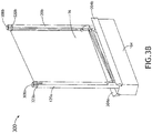
- FIG. 3B is a perspective view of a self-disinfecting partition system 300 configured in a partially deployed position, in accordance with one or more embodiments of the disclosure.
- the first screen attachment assembly 308a and/or a second screen attachment assembly 308b further includes a first screen clamp 320a and/or a second screen clamp 320b, respectively.
- the first screen clamp 320a and/or a second screen clamp 320b are coupled to the flexible screen (e.g., at the first border), and are slidably coupled to the first arm 304a and/or the second arm 304b, respectively.
- the first screen clamp 320a and second screen clamp 320b may be slid from the bottom end of the first arm 304a and/or the second arm 304b to the top end of the first arm 304a and/or the second arm 304b, wherein the first screen clamp 320a and/or second screen clamp 320b may be slid next to, or attached (e.g., via an interference fit) to components of the first screen attachment assembly 308a and/or a second screen attachment assembly 308b.
- the flexible screen 106 may be deployed back and forth from a retracted position to a deployed position (e.g., via the retraction assembly 200) and disinfected via the electromagnetic energy source 216.
- FIG. 4 is a perspective view of a self-disinfecting partition system 400 configured in a partially deployed position, in accordance with one or more embodiments of the disclosure.
- the self-disinfecting partition system 400 may include one or more, or all, components of self-disinfecting partition system 100, 300, and vice versa.
- the self-disinfecting partition system 400 is configured with only one arm 404 and a flexible screen 416 having a shape configured to retain a partition structure while being supported by the arm 404.
- the flexible screen 106 may be configured as a curved partition, as in FIG 4 .
- the arm 404 may be configured with one or more telescopic subunits 124 and telescope linearly into the housing.
- the arm may also be configured as a pivoting arm (e.g., configured with or without telescopic subunits 124) configured to pivot into the housing 104.
- a screen attachment assembly 404 e.g., a first screen assembly that includes a screen clamp 406 slidably coupled to the arm 404 and attached to the flexible screen 416, where sliding of the screen clamp 406 deploys the flexible screen 416 from a retracted to deployed position.
- FIG 5 is a drawing illustrating the attachment of two self-disinfecting partition systems 100a-b to a row of passenger seats 500a-c in accordance with one or more embodiments of the disclosure.
- the self-disinfecting partition systems 100, 300, 400 may be attached to any surface on or around the one or more passenger seats 500a-c including but not limited to an armrest 500a-b, headrest, seatback, overheat pin, floor, console, or other structure or chair component disposed between passenger seats 500a-c.
- the self-disinfecting partition systems 100, 300, 400 may be implemented in any orientation.
- the self-disinfecting partition system 100, 300, 400 may be attached to a structure (e.g., armrest) configured so that the flexible screen 106 is pulled upward from the retracted position to the deployed position (e.g., as in FIG. 5 ).
- the self-disinfecting partition system 100, 300, 400 may be attached to an overhead structure (e.g., overhead storage or ceiling) configured so that the flexible screen 106 is pulled downward from the retracted position to the deployed position.
- the self-disinfecting partition systems 100, 300, 400 may be placed on an adjacent side (e.g., upon the armrest) and configured so that the flexible screen 106 is pulled in a side-to-side motion from the retracted position to the deployed position.
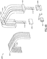
- FIG 6A and FIG. 6B are a perspective view and an exploded view, respectively, of a self-disinfecting partition system 600 configured in a retracted position, in accordance with one or more embodiments of the disclosure.
- the self-disinfecting partition system 600 may include one or more, or all, components of self-disinfecting partition system 100, 300, 400 and vice versa.
- the self-disinfecting partition system 600 includes a housing 602 configured to house a flexible screen 604.
- the housing 602 may be configured of any shape for form.
- the housing may be shaped to fit around or over the headrest and/or seatback of a seat (e.g., a passenger seat 500).
- the flexible screen 604 may be configured with an accordion fold, facilitating the transition from an extended, deployed position to a stored, retracted position.
- the flexible screen 604 may include a handle 605, whereby a user may grab the handle 605 and manually extend and/or retract the flexible screen 604.
- the self-disinfecting partition system 600 further includes an extension assembly 606a, 606b configured to raise and lower the housing relative to the seat (e.g., adjust the distance of the housing 602 from the at least one of the headrest or the seatback of the passenger seat 500).
- the extension assembly 606a, 606b comprises one or more attachment elements 608a, 608b and one or more supports 612a, 612b coupled to the housing 602 and configured to insert and slide within one or more apertures (e.g., tracks or holes) formed within the attachment elements 608a, 608b (e.g., the one or more supports 612a, 612b are slidably coupled to the one or more attachment elements 608a, 608b, with the one or more apertures within the attachment elements 608a, 608b configured to accept one or more supports 612a, 612b).
- one or more attachment elements 608a, 608b and one or more supports 612a, 612b coupled to the housing 602 and configured to insert and slide within one or more apertures (e.g., tracks or holes) formed within the attachment elements 608a, 608b (e.g., the one or more supports 612a, 612b are slidably coupled to the one or more attachment elements 608a, 608b, with the
- the one or more attachment elements 608a, 608b include one or more attachment surfaces 616a, 616b that may couple to any surface (e.g., the sides of a seatback of a seat) via any technology including but not limited to adhesive technology, bolts, screws, hook-and-loop, and suction.
- the one or more supports 612a, 612b may be of any shape or size and made of any material. Once the supports 612a, 612b are inserted within the one or more apertures within the seat-attached one or more attachment elements 612, the height of the housing 602 to be adjusted relative to the seat.
- a relatively tall person may pull upward on the housing 602 sliding the one or more supports 612a, 612, relative to the one or more attachment elements 608a, 608b, effectively raising the housing 602 so that the housing 602 will not interfere with the relatively tall person when seated.
- the self-disinfecting partition system 600 further includes a lock 620 coupled to one or more of the attachment elements 608a, 608b and configured to restrict the sliding of the one or more supports 612a, 612b, relative to the one or more attachment elements 608a, 608b.
- the lock 620 may be configured as any type of locking mechanism including but not limited to a friction lock, an interference lock, a clamp, a ratchet stay, and a tightening screw (e.g., with a friction fitting).
- the lock 620 may include a friction lock having a spring-loaded component (e.g., containing springs 632) that presses against one of the one or more supports 612a, 612b.
- the frictional force generated at the mating surface of the lock 620 and the one of the one or more supports 612a, 612b restricts movement of the housing to a set position. Adjustment of the lock 620 would then require manually pressing upon the lock in a fashion counter to the pressure of the supplied by the spring-loaded component, which reduces the friction applied by the lock 620, allowing the height of the housing to be adjusted.
- the self-disinfecting partition system 600 further includes one or more electromagnetic energy units 624a, 624b configured to deliver disinfecting amounts of electromagnetic energy.
- the self-disinfecting partition system 600 may be configured with electromagnetic energy units 624a, 624b disposed on both sides of the flexible screen.
- the self-disinfecting partition system 100, 300, 400, 600 may further include a battery 630 configured to power the electromagnetic energy units 624a, 624b and or the retraction assembly 200.
- the self-disinfecting partition system 100, 300, 400, 600 is powered by an external power source.
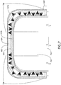
- FIG. 7 illustrates a close-up front view of the housing 602 of the self-disinfecting partition system 600 configured in a retracted position, in accordance with one or more embodiments of the disclosure.
- the housing 602 is shown closely conforming to a headrest 700 and a seatback 702 of a passenger seat 500.
- the electromagnetic energy units 624a, 624b are disposed on opposite sides of the retracted and folded flexible screen 604.
- Each electromagnetic energy unit 624a, 624b contains one or more electromagnetic energy sources 216.
- the electromagnetic energy sources 216 may be configured as any type electromagnetic energy and include any type or form of light-emitting technology as described herein.
- the electromagnetic energy sources 216 may be arranged into clusters 708 as shown in FIG. 7 .
- FIG. 8A and FIG. 8B illustrate perspective views of the self-disinfecting partition system 600 mounted on a passenger seat 500 configured in a retracted and deployed positions, respectively, in accordance with one or more embodiments of the disclosure.
- a passenger With the flexible screen 604 retracted, a passenger may easily access, sit down, and/or leave from the passenger seat 500.
- the passenger When sitting in the passenger seat 500, the passenger can freely deploy or retract the flexible screen 604 by pulling or pushing on the handle 605.
- the self-disinfecting partition system 100, 300, 400, 600 may further include any type of electrical system or scheme configured to power the one or more electromagnetic energy sources 216 and/or the retraction assembly.
- FIG. 9A is a block diagram illustrating an electrical scheme 900 within the self-disinfecting partition system 100, 300, 400, 600, in accordance with one or more embodiments of the disclosure.
- electrical scheme 900 may include the battery 630, the one or more electrical energy sources 216, and one or more switches 904.
- the electrical scheme 900 may include a switch 904 that is manually or automatically turned to an OFF or ON position, regulating the flow of electricity to power the one or more electromagnetic energy source 216.
- the electrical scheme may further include a switch 904 that is manually or automatically operated to activate or inactivate the retraction assembly 200.
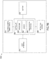
- FIG. 9B is a block diagram illustrating an electrical scheme 950 of the self-disinfecting partition system 100, 300, 400, 600, in accordance with one or more embodiments of the disclosure.
- the electrical scheme 950 includes the battery 630, the one or more electromagnetic energy sources 216, and/or the retraction assembly 200 as described herein.
- the electrical scheme 950 further includes a controller 954 configured to provide processing functionality for the self-disinfecting partition system 100, 300, 400, 600, and to interface with componentry within the self-disinfecting partition system 100, 300, 400, 600 including the battery 830, the electromagnetic energy source 216, and the user interface 972.
- the controller 954 further includes one or more processors 958 (e.g., micro-controllers, circuitry, integrated circuits, field programmable gate arrays (FPGA), or other processing systems), and resident or external memory 962 for storing data, executable code, instructions, and other information.
- the controller 954 can execute one or more software programs embodied in a non-transitory computer readable medium (e.g., memory 962) that implement techniques described herein (e.g., causing the controller 954 to implement techniques described herein).
- the controller 954 is not limited by the materials from which it is formed or the processing mechanisms employed therein and, as such, can be implemented via semiconductor(s) and/or transistors (e.g., using electronic integrated circuit (IC) components), and so forth.
- the memory 962 can be an example of tangible, computer-readable storage medium that provides storage functionality to store various data and/or program code associated with operation of the controller 954, such as software programs and/or code segments, or other data to instruct the controller 954, and possibly other components of the self-disinfecting partition system 100, 300, 400, 600, to perform the functionality described herein.
- the memory 962 can store data, such as a program of instructions for operating the self-disinfecting partition system 100, 300, 400, 600, including its components (e.g., controller 954), and so forth.
- controller 954 e.g., controller 954
- the memory 962 can be integral with the controller 954, can comprise stand-alone memory, or can be a combination of both. Some examples of the memory 962 can include removable and non-removable memory components, such as random-access memory (RAM), read-only memory (ROM), flash memory (e.g., a secure digital (SD) memory card, a mini-SD memory card, and/or a micro-SD memory card), solid-state drive (SSD) memory, magnetic memory, optical memory, universal serial bus (USB) memory devices, hard disk memory, external memory, and so forth.
- RAM random-access memory
- ROM read-only memory
- flash memory e.g., a secure digital (SD) memory card, a mini-SD memory card, and/or a micro-SD memory card
- SSD solid-state drive
- magnetic memory magnetic memory
- optical memory optical memory
- USB universal serial bus
- the controller 954 further includes a communication interface 968.
- the communication interface 968 can be operatively configured to communicate with components of the self-disinfecting partition system 100, 300, 400, 600.
- the communication interface 968 can be configured to retrieve data from the controller 954 or other components, transmit data for storage in the memory 962, retrieve data from storage in the memory 962, and so forth.
- the communication interface 968 can also be communicatively coupled with the controller 954 to facilitate data transfer between components of the self-disinfecting partition system 100, 300, 400, 600. It should be noted that while the communication interface 968 is described as a component of the controller 954, one or more components of the communication interface 968 can be implemented as external components communicatively coupled to the controller 954 via a wired and/or wireless connection.
- the electrical scheme 950 further includes a user interface 972 configured communicatively coupled to the controller 954.
- the user interface 1024 may include any technology that can receive input and/or transmit output to a user including but not limited to switches, button, displays, touch displays, or keyboards.
- the user interface 972 may also be configured as a wirelines or wireless interface utilizing waveforms including but not limited to wi-fi, Bluetooth, and 5G.
- a flight attendant may interact with the self-disinfecting partition system 100, 300, 400, 600 via a mobile device (e.g., a smart phone) connected by Bluetooth technology.
- embodiments of the methods disclosed herein may include one or more of the steps described herein. Further, such steps may be carried out in any desired order and two or more of the steps may be carried out simultaneously with one another. Two or more of the steps disclosed herein may be combined in a single step, and in some embodiments, one or more of the steps may be carried out as two or more sub-steps. Further, other steps or sub-steps may be carried in addition to, or as substitutes to one or more of the steps disclosed herein.
Landscapes
- Health & Medical Sciences (AREA)
- Engineering & Computer Science (AREA)
- Public Health (AREA)
- Epidemiology (AREA)
- Life Sciences & Earth Sciences (AREA)
- Animal Behavior & Ethology (AREA)
- General Health & Medical Sciences (AREA)
- Aviation & Aerospace Engineering (AREA)
- Veterinary Medicine (AREA)
- Mechanical Engineering (AREA)
- Transportation (AREA)
- Apparatus For Disinfection Or Sterilisation (AREA)
- Passenger Equipment (AREA)
Abstract
Description
- The present application claims the benefit under 35 U.S.C. § 119(e) of
Indian Provisional App. No. 202011024785 (filed June 12, 2020 - The transfer of microbes (e.g., virus, bacteria, or fungus) from person to person has become a greater concern over time due to recent pandemics. The commercial aircraft industry is particularly concerned about person-to-person transfer of microbes, as flight in an aircraft often necessitates congregating diverse groups of people in a constricted area for long periods of time.
- To reduce the risk of transmission, barriers may be implemented between passengers to block or reduce microbial transfer. However, these barriers need to be disinfected often. The disinfection of these barriers often includes manual spraying and wiping surfaces with disinfection solution, a method that is time consuming, and may use toxic materials that may degrade aircraft interior surfaces over time. Accordingly, it is desirable to provide a system that avoids the shortcomings of conventional approaches.
- A self-disinfecting partition system is disclosed. In one or more embodiments, the self-disinfecting partition system includes a housing. In one or more embodiments, the housing includes an attachment element configured to attach the housing to a first surface. In one or more embodiments, the housing further includes an opening. In one or more embodiments, the self-disinfecting partition system further includes a flexible screen configured to restrict a transmission of microbes, and further configured to deploy from a retracted position within the housing to a deployed position at least partially outside of the opening. In one or more embodiments, the self-disinfecting partition system further includes a first arm mechanically coupled to an interior of the housing and configured to deploy from a first stored position within the housing to a first extended position at least partially outside of the opening. In one or more embodiments, the first arm includes a first screen attachment assembly coupled to a first end of the one arm, wherein the first end of the one arm is configured to attach to a first border of the flexible screen. In one or more embodiments, the self-disinfecting partition system further includes a retraction assembly configured to retract the flexible screen from the deployed position to the retracted position. In one or more embodiments, the retraction assembly includes a reel configured to wind the flexible screen. In one or more embodiments, the retraction assembly further includes one or more guide rollers configured to guide the flexible screen onto the reel. In one or more embodiments, the self-disinfecting partition system further includes an electromagnetic energy source disposed within the housing configured to emit electromagnetic energy onto the flexible screen, wherein the electromagnetic energy is configured to disinfect the flexible screen.
- In some embodiments of the self-disinfecting partition system, the self-disinfecting partition system further includes a second arm mechanically coupled to the housing and configured to deploy from a second stored position within the housing to a second extended position at least partially outside of the housing. In some embodiments, the second arm includes a second screen attachment assembly coupled to a first end of the second arm, wherein the first end of the second arm is configured to attach to the first border of the flexible screen.
- In some embodiments of the self-disinfecting partition system, the first arm is further configured to telescope.
- In some embodiments of the self-disinfecting partition system, the first screen attachment assembly is in constant contact with the first border of the flexible screen as the flexible screen is deployed from the retracted position to the deployed position.
- In some embodiments of the self-disinfecting partition system, the self-disinfecting partition system, further includes a connecting rod attached to the first screen attachment assembly and the second attachment assembly, wherein the connecting rod is coupled to the first border of the flexible screen.
- In some embodiments of the self-disinfecting partition system, the self-disinfecting partition system further includes at least one door coupled to the housing configured to cover the opening when the first arm is retracted inside the housing.
- In some embodiments of the self-disinfecting partition system, the first arm is further configured to rotate from a stored position to the extended position via a first joint.
- In some embodiments of the self-disinfecting partition system, the first screen attachment assembly further includes a first screen clamp coupled to the flexible screen and slidably coupled to the first arm.
- In some embodiments of the self-disinfecting partition system, the retraction assembly further comprises a rotary actuator configured to rotate the reel.
- In some embodiments of the self-disinfecting partition system, the self-disinfecting partition system further comprises an electrical scheme configured to power at least one of the electromagnetic energy source or the retraction assembly.
- In some embodiments of the self-disinfecting partition system, the self-disinfecting partition system further comprises a user interface communicatively coupled to the electrical scheme.
- Another self-disinfecting partition system is disclosed. In one or more embodiments, the self-disinfecting partition system includes a housing. In one or more embodiments, the self-disinfecting partition system further includes an attachment element configured to couple the self-disinfecting partition system to the seat. In one or more embodiments, the attachment element includes one or more apertures configured to accept one or more supports. In one or more embodiments, the self-disinfecting partition system further includes an extension assembly coupled to the housing and the attachment element. In one or more embodiments, the extension assembly includes the one or more supports coupled to the housing and configured to slide within the one or more apertures, wherein sliding of the one or more supports within the one or more apertures adjusts a distance of the housing from the seat. In one or more embodiments, the extension assembly further includes a lock coupled to the attachment element and operationally coupled to the one or more supports and the one or more apertures; wherein the lock is configured upon activation to restrict a movement of the one or more supports relative to the one or more apertures. In one or more embodiments, the self-disinfecting partition system further includes a flexible screen configured to block a transmission of microbes, and further configured to deploy from a retracted position within the housing to a deployed position. In one or more embodiments, the self-disinfecting partition system further includes one or more electromagnetic energy sources disposed within the housing configured to emit electromagnetic energy onto the flexible screen when the flexible screen is configured in the retracted position, wherein the electromagnetic energy is configured to disinfect the flexible screen.
- In some embodiments of the self-disinfecting partition system, the flexible screen is configured to retract via an accordion fold.
- In some embodiments of the self-disinfecting partition system, the self-disinfecting partition system further includes an electrical scheme configured to power at least one of the electromagnetic energy source.
- In some embodiments of the self-disinfecting partition system, the self-disinfecting partition system further includes a user interface communicatively coupled to the electrical scheme.
- This Summary is provided solely as an introduction to subject matter that is fully described in the Detailed Description and Drawings. The Summary should not be considered to describe essential features nor be used to determine the scope of the Claims. Moreover, it is to be understood that both the foregoing Summary and the following Detailed Description are example and explanatory only and are not necessarily restrictive of the subject matter claimed.
- The detailed description is described with reference to the accompanying figures. The use of the same reference numbers in different instances in the description and the figures may indicate similar or identical items. Various embodiments or examples ("examples") of the present disclosure are disclosed in the following detailed description and the accompanying drawings. The drawings are not necessarily to scale. In general, operations of disclosed processes may be performed in an arbitrary order, unless otherwise provided in the claims. In the drawings:
-
FIG. 1A is a perspective view of a self-disinfecting partition system configured in a retracted position, in accordance with one or more embodiments of the disclosure; -
FIG. 1B is a perspective view of a self-disinfecting partition system with the flexible screen extended in a deployed configuration, in accordance with one or more embodiments of the disclosure; -
FIG. 2 is a side cutaway view of the self-disinfecting partition system configured in a retracted position, in accordance with one or more embodiments of the disclosure; -
FIG. 3A is a perspective view of a self-disinfecting partition system configured in a partially deployed position, in accordance with one or more embodiments of the disclosure; -
FIG. 3B is a perspective view of a self-disinfectingpartition system 300 configured in a partially deployed position, in accordance with one or more embodiments of the disclosure; -
FIG. 4 is a perspective view of a self-disinfecting partition system configured in a partially deployed position, in accordance with one or more embodiments of the disclosure; -
FIG. 5 is a drawing illustrating the attachment of two self-disinfecting partition systems a row of passenger seats in accordance with one or more embodiments of the disclosure; -
FIG 6A is a perspective view of a self-disinfecting partition system configured in a retracted position, in accordance with one or more embodiments of the disclosure; -
FIG 6A is an exploded view of a self-disinfecting partition system configured in a retracted position, in accordance with one or more embodiments of the disclosure; -
FIG. 7 illustrates a close-up front view of the housing of the self-disinfecting partition system configured in a retracted position, in accordance with one or more embodiments of the disclosure; -
FIG. 8A illustrates a perspective view of the self-disinfecting partition system mounted on a passenger seat configured in a retracted position, in accordance with one or more embodiments of the disclosure. -
FIG. 8B illustrates a perspective view of the self-disinfecting partition system mounted on a passenger seat configured in a deployed position, in accordance with one or more embodiments of the disclosure. -
FIG. 9A is a block diagram illustrating an electrical scheme within the self-disinfecting partition system, in accordance with one or more embodiments of the disclosure. -
FIG. 9B is a block diagram illustrating an electrical scheme of the self-disinfecting partition system, in accordance with one or more embodiments of the disclosure. - Before explaining one or more embodiments of the disclosure in detail, it is to be understood that the embodiments are not limited in their application to the details of construction and the arrangement of the components or steps or methodologies set forth in the following description or illustrated in the drawings. In the following detailed description of embodiments, numerous specific details may be set forth in order to provide a more thorough understanding of the disclosure. However, it will be apparent to one of ordinary skill in the art having the benefit of the instant disclosure that the embodiments disclosed herein may be practiced without some of these specific details. In other instances, well-known features may not be described in detail to avoid unnecessarily complicating the instant disclosure.
- As used herein a letter following a reference numeral is intended to reference an embodiment of the feature or element that may be similar, but not necessarily identical, to a previously described element or feature bearing the same reference numeral (e.g., 1, 1a, 1b). Such shorthand notations are used for purposes of convenience only and should not be construed to limit the disclosure in any way unless expressly stated to the contrary.
- Further, unless expressly stated to the contrary, "or" refers to an inclusive or and not to an exclusive or. For example, a condition A or B is satisfied by anyone of the following: A is true (or present) and B is false (or not present), A is false (or not present) and B is true (or present), and both A and B are true (or present).
- In addition, use of "a" or "an" may be employed to describe elements and components of embodiments disclosed herein. This is done merely for convenience and "a" and "an" are intended to include "one" or "at least one," and the singular also includes the plural unless it is obvious that it is meant otherwise.
- Finally, as used herein any reference to "one embodiment" or "some embodiments" means that a particular element, feature, structure, or characteristic described in connection with the embodiment is included in at least one embodiment disclosed herein. The appearances of the phrase "in some embodiments" in various places in the specification are not necessarily all referring to the same embodiment, and embodiments may include one or more of the features expressly described or inherently present herein, or any combination of sub-combination of two or more such features, along with any other features which may not necessarily be expressly described or inherently present in the instant disclosure.
- A self-disinfecting partition system is disclosed. The self-disinfecting partition system may be used to prevent communication of microbes between people, such as passengers on an aircraft, via a deployable partition screen that retracts from a housing. When not in use, the partition screen may be retracted into the housing. Electromagnetic energy (e.g., ultraviolet light) scanners within the housing scan the partition screen while the partition screen is retracting and/or retracted, sterilizing microbes that have attached themselves to the screen.
-
FIG. 1A is a perspective view of a self-disinfectingpartition system 100 configured in a retracted position, in accordance with one or more embodiments of the disclosure. The self-disinfectingpartition system 100 is configured to configured to block, or otherwise hinder, the transmission of pathogens (e.g., bacteria, viruses, or fungi) from one person to another. The self-disinfectingpartition system 100 may be configured for use in a wide variety of environments including but not limited to vehicles (e.g., aircraft, buses, trains, taxis) medical reception areas, ticket counters, payment terminals (e.g., at supermarkets), movie theaters and other public venues. For example, the self-disinfectingpartition system 100 may be configured for use on a passenger seat of a commercial aircraft. - In embodiments, the self-disinfecting
partition system 100 includes ahousing 104 that houses one or more components of the self-disinfectingpartition system 100. Thehousing 104 may be configured of any shape of form including but not limited to a rectangular prism. self-disinfectingpartition system 100 further includes a flexible screen 106 (e.g., mostly hidden from view inFIG. 1A ). Theflexible screen 106 is stored in a retracted position within thehousing 104 when not in use (e.g., as inFIG. 1A ), then subsequently extended into a deployed position when in (e.g., as inFIG. 1B ). Theflexible screen 106 may be of any size of shape, and may be constructed of any material included but limited to cloth, fiber, nylon, or plastic. - In some embodiments, the self-disinfecting
partition system 100 further includes a firstscreen attachment assembly 108a and/or a secondscreen attachment assembly 108b configured to attach to a first border of theflexible screen 106. The first border of theflexible screen 106 may be considered a strip of a relatively small width (e.g., approximately 2 cm) of the leading edge of theflexible screen 106. The firstscreen attachment assembly 108a and/or a secondscreen attachment assembly 108b may use any type of technology to attach to the first border of the flexible screen including but not limited the use of clamps, adhesives, and crimping. - In some embodiments, the first
screen attachment assembly 108a and/or the secondscreen attachment assembly 108b further includes a connectingrod 112 coupled to the firstscreen attachment assembly 108a and the secondscreen attachment assembly 108b (e.g., the connecting rod provides the major attachment point of theflexible screen 106 and acts as an extension of the firstscreen attachment assembly 108a and/or the secondscreen attachment assembly 108b.) The connectingrod 112 may be attached to the firstscreen attachment assembly 108a and/or the secondscreen attachment assembly 108b using any technology including but not limited to a bushing. -
FIG. 1B is a perspective view of a self-disinfectingpartition system 100 with theflexible screen 106 extended in a deployed configuration, in accordance with one or more embodiments of the disclosure. The extension of the flexible screen may be accomplished by manually pulling upwards on the connecting rod. In some embodiments, the extension of the flexible screen is accomplished through a rotary actuator disposed within the housing 104 (e.g., electrically powered, or powered by a spring). - The extension of the
flexible screen 106 from thehousing 104 exposes afirst arm 120a and asecond arm 120b that rise from thehousing 104 to support the flexible screen. For example, a first end of the first arm 120 may be coupled to the firstscreen attachment assembly 108a, whereas asecond end 122b of the second arm may be attached to the secondscreen attachment assembly 108b. In some embodiments, thefirst arm 120a and/orsecond arm 120b may be configured withtelescopic subunits 124a-f, allowing thefirst arm 120a and/orsecond arm 120b to straightforwardly extend and/or retract into thehousing 104. In this manner, thescreen attachment assemblies flexible screen 106 as theflexible screen 106 is deployed from the retracted position to the deployed position. -
FIG. 2 is a side cutaway view of the self-disinfectingpartition system 100 configured in a retracted position, in accordance with one or more embodiments of the disclosure. In some embodiments, the self-disinfectingpartition system 100 further includes aretraction assembly 200 configured to guide and/or power theflexible screen 106 into thehousing 104. Theretraction assembly 200 may include areel 204 attached to an end border of the flexible screen 106 (e.g., the border of theflexible screen 116 opposite of the first border). Upon retraction of theflexible screen 106, thereel 204 may actuate via a rotary actuator 212 (e.g., a loaded spring or electric motor), effectively winding theflexible screen 106 upon thereel 204. - In some embodiments, the retraction assembly further includes one or
more guide rollers 208a-c configured to guide theflexible screen 106 onto thereel 204. For example, a pair ofguide rollers flexible screen 106, acting to guide theflexible screen 106 toward thereel 204 and/or provide facilitate a tension upon theflexible screen 106 so that theflexible screen 106 may be properly wound. - In some embodiments, the housing further includes one or more
electromagnetic energy sources 216 configured to emit electromagnetic energy onto theflexible screen 106. The one or moreelectromagnetic energy sources 216 may emit any type of electromagnetic energy that disinfects/sterilized theflexible screen 106 including but not limited to ultraviolet light and X-rays. For example, theelectromagnetic energy sources 216 may include any type or form of ultraviolet light-emitting technology including but not limited to light-emitting diodes (LED), mercury vapor lights, shortwave fluorescent lamp tubes, "black light" incandescent lamps, gas-discharge lamps, and lasers. For example, one or moreelectromagnetic energy sources 216 may be configured as an ultraviolet-emitting LED. The self-disinfectingpartition system 100 may use any number, size, type, or configuration of the one or moreelectromagnetic energy sources 216. For example, the housing may include two lines of ultraviolet-emitting LEDs that run along opposing interior sides of thehousing 104. - In some embodiments, the one or more
electromagnetic energy sources 216 emit electromagnetic energy only while the flexible screen is being retracted or deployed. In some embodiments, the electromagnetic energy sources 2016 emit electromagnetic energy while flexible screen has been fully deployed (e.g., for a set amount of time). - In some embodiments, the
housing 104 may include one ormore attachment elements 220 configured to attach thehousing 104 to a surface (e.g., the surface of a chair, armrest, setback, headrest, overhead bin, or side console). The one ormore attachment elements 220 may including any type of attachment technology including but limited to adhesives, bolts, screws, hook-and-loop, suction or an interference fit. In some embodiments, the housing further includes acap 205. -
FIG. 3A is a perspective view of a self-disinfectingpartition system 300 configured in a partially deployed position, in accordance with one or more embodiments of the disclosure. The self-disinfectingpartition system 300 may include one or more, or all, components of the self-disinfectingpartition system 100, and vice versa. In some embodiments, thefirst arm 304a and/orsecond arm 304b self-disinfectingpartition system 300 are configured to rotate or swing out from thehousing 104 into a first extended position via a joint 302 (e.g., only visible for thesecond arm 304b) operationally coupled to thehousing 104. Thefirst arm 304a and/orsecond arm 304b may be manually rotated or rotated via an actuator. In some embodiments of the self-disinfectingpartition system 300, theflexible screen 106 includes a firstscreen attachment assembly 308a and/or a secondscreen attachment assembly 308b that attaches to theflexible screen 106 after thefirst arm 304a and/or thesecond arm 304b has been deployed (e.g., as shown inFIG. 3B ). In some embodiments, thefirst arm 304a and/or thesecond arm 304b of the self-disinfectingpartition system 300 may be further extended via telescopic subunits 124. - In some embodiments, the self-disinfecting
partition system 300 further includes one ormore doors housing 104 configured to cover anopening 316 of the housing. The one or more doors prevent the electromagnetic energy (e.g., ultraviolet light) from escaping thehousing 104 when theflexible screen 106 is retracted. The one ormore doors more doors electromagnetic energy source 216 will automatically shut off if the one or more doors is opened, preventing the transmission of potentially harmful electromagnetic energy to a person. -
FIG. 3B is a perspective view of a self-disinfectingpartition system 300 configured in a partially deployed position, in accordance with one or more embodiments of the disclosure. In some embodiments, the firstscreen attachment assembly 308a and/or a secondscreen attachment assembly 308b further includes afirst screen clamp 320a and/or asecond screen clamp 320b, respectively. Thefirst screen clamp 320a and/or asecond screen clamp 320b are coupled to the flexible screen (e.g., at the first border), and are slidably coupled to thefirst arm 304a and/or thesecond arm 304b, respectively. When thefirst arm 304a and/or thesecond arm 304b are deployed, thefirst screen clamp 320a andsecond screen clamp 320b may be slid from the bottom end of thefirst arm 304a and/or thesecond arm 304b to the top end of thefirst arm 304a and/or thesecond arm 304b, wherein thefirst screen clamp 320a and/orsecond screen clamp 320b may be slid next to, or attached (e.g., via an interference fit) to components of the firstscreen attachment assembly 308a and/or a secondscreen attachment assembly 308b. In this manner, theflexible screen 106 may be deployed back and forth from a retracted position to a deployed position (e.g., via the retraction assembly 200) and disinfected via theelectromagnetic energy source 216. -
FIG. 4 is a perspective view of a self-disinfecting partition system 400 configured in a partially deployed position, in accordance with one or more embodiments of the disclosure. The self-disinfecting partition system 400 may include one or more, or all, components of self-disinfectingpartition system - In some embodiments, the self-disinfecting partition system 400 is configured with only one
arm 404 and aflexible screen 416 having a shape configured to retain a partition structure while being supported by thearm 404. For example, theflexible screen 106 may be configured as a curved partition, as inFIG 4 . In some embodiments, thearm 404 may be configured with one or more telescopic subunits 124 and telescope linearly into the housing. The arm may also be configured as a pivoting arm (e.g., configured with or without telescopic subunits 124) configured to pivot into thehousing 104. In this manner, a screen attachment assembly 404 (e.g., a first screen assembly that includes ascreen clamp 406 slidably coupled to thearm 404 and attached to theflexible screen 416, where sliding of thescreen clamp 406 deploys theflexible screen 416 from a retracted to deployed position. -
FIG 5 is a drawing illustrating the attachment of two self-disinfectingpartition systems 100a-b to a row ofpassenger seats 500a-c in accordance with one or more embodiments of the disclosure. The self-disinfectingpartition systems more passenger seats 500a-c including but not limited to anarmrest 500a-b, headrest, seatback, overheat pin, floor, console, or other structure or chair component disposed betweenpassenger seats 500a-c. - The self-disinfecting
partition systems partition system flexible screen 106 is pulled upward from the retracted position to the deployed position (e.g., as inFIG. 5 ). In another example, the self-disinfectingpartition system flexible screen 106 is pulled downward from the retracted position to the deployed position. In another example, the self-disinfectingpartition systems flexible screen 106 is pulled in a side-to-side motion from the retracted position to the deployed position. -
FIG 6A andFIG. 6B are a perspective view and an exploded view, respectively, of a self-disinfectingpartition system 600 configured in a retracted position, in accordance with one or more embodiments of the disclosure. The self-disinfectingpartition system 600 may include one or more, or all, components of self-disinfectingpartition system - In some embodiments, the self-disinfecting
partition system 600 includes ahousing 602 configured to house aflexible screen 604. Thehousing 602 may be configured of any shape for form. For example, the housing may be shaped to fit around or over the headrest and/or seatback of a seat (e.g., a passenger seat 500). Theflexible screen 604 may be configured with an accordion fold, facilitating the transition from an extended, deployed position to a stored, retracted position. Theflexible screen 604 may include ahandle 605, whereby a user may grab thehandle 605 and manually extend and/or retract theflexible screen 604. - In some embodiments, the self-disinfecting
partition system 600 further includes anextension assembly housing 602 from the at least one of the headrest or the seatback of the passenger seat 500). Theextension assembly more attachment elements more supports housing 602 and configured to insert and slide within one or more apertures (e.g., tracks or holes) formed within theattachment elements more supports more attachment elements attachment elements more supports more attachment elements more attachment surfaces more supports supports housing 602 to be adjusted relative to the seat. For example, upon attachment of the self-disinfectingpartition system 600 to a seat, a relatively tall person may pull upward on thehousing 602 sliding the one ormore supports 612a, 612, relative to the one ormore attachment elements housing 602 so that thehousing 602 will not interfere with the relatively tall person when seated. - In some embodiments, the self-disinfecting
partition system 600 further includes alock 620 coupled to one or more of theattachment elements more supports more attachment elements lock 620 may be configured as any type of locking mechanism including but not limited to a friction lock, an interference lock, a clamp, a ratchet stay, and a tightening screw (e.g., with a friction fitting). For example, thelock 620 may include a friction lock having a spring-loaded component (e.g., containing springs 632) that presses against one of the one ormore supports lock 620 and the one of the one ormore supports lock 620 would then require manually pressing upon the lock in a fashion counter to the pressure of the supplied by the spring-loaded component, which reduces the friction applied by thelock 620, allowing the height of the housing to be adjusted. - In some embodiments, the self-disinfecting
partition system 600 further includes one or moreelectromagnetic energy units partition system 600 may be configured withelectromagnetic energy units partition system battery 630 configured to power theelectromagnetic energy units retraction assembly 200. In some embodiments, the self-disinfectingpartition system -
FIG. 7 illustrates a close-up front view of thehousing 602 of the self-disinfectingpartition system 600 configured in a retracted position, in accordance with one or more embodiments of the disclosure. Thehousing 602 is shown closely conforming to aheadrest 700 and a seatback 702 of apassenger seat 500. Theelectromagnetic energy units flexible screen 604. Eachelectromagnetic energy unit electromagnetic energy sources 216. Theelectromagnetic energy sources 216 may be configured as any type electromagnetic energy and include any type or form of light-emitting technology as described herein. For example, theelectromagnetic energy sources 216 may be arranged intoclusters 708 as shown inFIG. 7 . -
FIG. 8A andFIG. 8B illustrate perspective views of the self-disinfectingpartition system 600 mounted on apassenger seat 500 configured in a retracted and deployed positions, respectively, in accordance with one or more embodiments of the disclosure. With theflexible screen 604 retracted, a passenger may easily access, sit down, and/or leave from thepassenger seat 500. When sitting in thepassenger seat 500, the passenger can freely deploy or retract theflexible screen 604 by pulling or pushing on thehandle 605. - The self-disinfecting
partition system electromagnetic energy sources 216 and/or the retraction assembly.FIG. 9A is a block diagram illustrating an electrical scheme 900 within the self-disinfectingpartition system battery 630, the one or moreelectrical energy sources 216, and one ormore switches 904. For instance, the electrical scheme 900 may include aswitch 904 that is manually or automatically turned to an OFF or ON position, regulating the flow of electricity to power the one or moreelectromagnetic energy source 216. In another example, the electrical scheme may further include aswitch 904 that is manually or automatically operated to activate or inactivate theretraction assembly 200. -
FIG. 9B is a block diagram illustrating anelectrical scheme 950 of the self-disinfectingpartition system electrical scheme 950 includes thebattery 630, the one or moreelectromagnetic energy sources 216, and/or theretraction assembly 200 as described herein. In some embodiments, theelectrical scheme 950 further includes a controller 954 configured to provide processing functionality for the self-disinfectingpartition system partition system electromagnetic energy source 216, and theuser interface 972. The controller 954 further includes one or more processors 958 (e.g., micro-controllers, circuitry, integrated circuits, field programmable gate arrays (FPGA), or other processing systems), and resident orexternal memory 962 for storing data, executable code, instructions, and other information. The controller 954 can execute one or more software programs embodied in a non-transitory computer readable medium (e.g., memory 962) that implement techniques described herein (e.g., causing the controller 954 to implement techniques described herein). The controller 954 is not limited by the materials from which it is formed or the processing mechanisms employed therein and, as such, can be implemented via semiconductor(s) and/or transistors (e.g., using electronic integrated circuit (IC) components), and so forth. - The
memory 962 can be an example of tangible, computer-readable storage medium that provides storage functionality to store various data and/or program code associated with operation of the controller 954, such as software programs and/or code segments, or other data to instruct the controller 954, and possibly other components of the self-disinfectingpartition system memory 962 can store data, such as a program of instructions for operating the self-disinfectingpartition system single memory 962 is described, a wide variety of types and combinations of memory 962 (e.g., tangible, non-transitory memory) can be employed. Thememory 962 can be integral with the controller 954, can comprise stand-alone memory, or can be a combination of both. Some examples of thememory 962 can include removable and non-removable memory components, such as random-access memory (RAM), read-only memory (ROM), flash memory (e.g., a secure digital (SD) memory card, a mini-SD memory card, and/or a micro-SD memory card), solid-state drive (SSD) memory, magnetic memory, optical memory, universal serial bus (USB) memory devices, hard disk memory, external memory, and so forth. - The controller 954 further includes a
communication interface 968. Thecommunication interface 968 can be operatively configured to communicate with components of the self-disinfectingpartition system communication interface 968 can be configured to retrieve data from the controller 954 or other components, transmit data for storage in thememory 962, retrieve data from storage in thememory 962, and so forth. Thecommunication interface 968 can also be communicatively coupled with the controller 954 to facilitate data transfer between components of the self-disinfectingpartition system communication interface 968 is described as a component of the controller 954, one or more components of thecommunication interface 968 can be implemented as external components communicatively coupled to the controller 954 via a wired and/or wireless connection. - The
electrical scheme 950 further includes auser interface 972 configured communicatively coupled to the controller 954. The user interface 1024 may include any technology that can receive input and/or transmit output to a user including but not limited to switches, button, displays, touch displays, or keyboards. Theuser interface 972 may also be configured as a wirelines or wireless interface utilizing waveforms including but not limited to wi-fi, Bluetooth, and 5G. For example, a flight attendant may interact with the self-disinfectingpartition system - It is to be understood that embodiments of the methods disclosed herein may include one or more of the steps described herein. Further, such steps may be carried out in any desired order and two or more of the steps may be carried out simultaneously with one another. Two or more of the steps disclosed herein may be combined in a single step, and in some embodiments, one or more of the steps may be carried out as two or more sub-steps. Further, other steps or sub-steps may be carried in addition to, or as substitutes to one or more of the steps disclosed herein.
- Although inventive concepts have been described with reference to the embodiments illustrated in the attached drawing figures, equivalents may be employed and substitutions made herein without departing from the scope of the claims. Components illustrated and described herein are merely examples of a system/device and components that may be used to implement embodiments of the inventive concepts and may be replaced with other devices and components without departing from the scope of the claims. Furthermore, any dimensions, degrees, and/or numerical ranges provided herein are to be understood as non-limiting examples unless otherwise specified in the claims.
Claims (15)
- A self-disinfecting partition system comprising:a housing (104) comprising:an attachment element (608a, 608b) configured to attach the housing to a first surface; andan opening (316);a flexible screen (106) configured to restrict a transmission of microbes, and further configured to deploy from a retracted position within the housing to a deployed position at least partially outside of the opening;a first arm (304a) mechanically coupled to an interior of the housing and configured to deploy from a first stored position within the housing to a first extended position at least partially outside of the opening, the first arm comprising a first screen attachment assembly coupled to a first end of the one arm, wherein the first end of the one arm is configured to attach to a first border of the flexible screen;a retraction assembly (200) configured to retract the flexible screen from the deployed position to the retracted position comprising:a reel (204) configured to wind the flexible screen; andone or more guide rollers (208a, 208b) configured to guide the flexible screen onto the reel; andan electromagnetic energy source (216) disposed within the housing configured to emit electromagnetic energy onto the flexible screen, wherein the electromagnetic energy is configured to disinfect the flexible screen.
- The self-disinfecting system of claim 1, further comprising a second arm mechanically coupled to the housing and configured to deploy from a second stored position within the housing to a second extended position at least partially outside of the housing, the second arm comprising a second screen attachment assembly coupled to a first end of the second arm, wherein the first end of the second arm is configured to attach to the first border of the flexible screen.
- The self-disinfecting partition system of any preceding claim, wherein the first arm is further configured to telescope.
- The self-disinfecting partition system of claim 3, wherein the first screen attachment assembly is in constant contact with the first border of the flexible screen as the flexible screen is deployed from the retracted position to the deployed position.
- The self-disinfecting partition system of claim 4, further comprising a connecting rod attached to the first screen attachment assembly and the second attachment assembly, wherein the connecting rod is coupled to the first border of the flexible screen.
- The self-disinfecting partition system of any preceding claim, further comprising at least one door coupled to the housing configured to cover the opening when the first arm is retracted inside the housing.
- The self-disinfecting partition system of any preceding claim, wherein the first arm is further configured to rotate from a stored position to the extended position via a first joint.
- The self-disinfecting partition system of any preceding claim, wherein the first screen attachment assembly further comprises a first screen clamp coupled to the flexible screen and slidably coupled to the first arm.
- The self-disinfecting partition system of any preceding claim, wherein the retraction assembly further comprises a rotary actuator configured to rotate the reel.
- The self-disinfecting partition system of any preceding claim, further comprising an electrical scheme configured to power at least one of the electromagnetic energy source or the retraction assembly.
- The self-disinfecting partition system of claim 10, further comprising a user interface communicatively coupled to the electrical scheme.
- A self-disinfecting partition system comprising:a housing (104);an attachment element (608a, 608b) configured to couple the housing to a seat comprising one or more apertures configured to accept one or more supports;an extension assembly (606a, 606b) coupled to the housing and the attachment element, comprising:the one or more supports (612a, 612b) coupled to the housing and configured to slide within the one or more apertures, wherein sliding of the one or more supports within the one or more apertures adjusts a distance of the housing from the seat; anda lock (620) coupled to the attachment element and operationally coupled to the one or more supports and the one or more apertures; wherein the lock is configured upon activation to restrict a movement of the one or more supports relative to the one or more apertures;a flexible screen (106) configured to block a transmission of microbes, and further configured to deploy from a retracted position within the housing to a deployed position; andone or more electromagnetic energy sources (216) disposed within the housing configured to emit electromagnetic energy onto the flexible screen when the flexible screen is configured in the retracted position, wherein the electromagnetic energy is configured to disinfect the flexible screen.
- The self-disinfecting partition system of claim 12, wherein the flexible screen is configured to retract via an accordion fold.
- The self-disinfecting partition system of claim 12, further comprising an electrical scheme configured to power at least one of the electromagnetic energy source.
- The self-disinfecting partition system of claim 14, further comprising a user interface communicatively coupled to the electrical scheme.
Applications Claiming Priority (2)
| Application Number | Priority Date | Filing Date | Title |
|---|---|---|---|
| IN202011024785 | 2020-06-12 | ||
| US17/340,451 US12325523B2 (en) | 2020-06-12 | 2021-06-07 | Self-disinfecting portable physical partitions for aircraft interiors |
Publications (3)
| Publication Number | Publication Date |
|---|---|
| EP3922558A2 true EP3922558A2 (en) | 2021-12-15 |
| EP3922558A3 EP3922558A3 (en) | 2022-03-16 |
| EP3922558B1 EP3922558B1 (en) | 2024-03-20 |
Family
ID=76764796
Family Applications (1)
| Application Number | Title | Priority Date | Filing Date |
|---|---|---|---|
| EP21179049.8A Active EP3922558B1 (en) | 2020-06-12 | 2021-06-11 | Self-disinfecting portable physical partitions for aircraft interiors |
Country Status (1)
| Country | Link |
|---|---|
| EP (1) | EP3922558B1 (en) |
Cited By (2)
| Publication number | Priority date | Publication date | Assignee | Title |
|---|---|---|---|---|
| EP4008362A1 (en) * | 2020-05-21 | 2022-06-08 | HCL America Inc. | Aircraft sanitization systems and devices |
| CN120773781A (en) * | 2025-08-13 | 2025-10-14 | 沪强企业(盐城)有限公司 | Table support for supporting back table of rail transit seat |
Family Cites Families (9)
| Publication number | Priority date | Publication date | Assignee | Title |
|---|---|---|---|---|
| DE2323833C3 (en) * | 1973-05-11 | 1981-02-05 | Linke-Hofmann-Busch, Waggon-Fahrzeug- Maschinen Gmbh, 3320 Salzgitter | Arrangement on seats for vehicles, in particular rail vehicles |
| US4825921A (en) * | 1986-05-07 | 1989-05-02 | Rigter Steven M | Blinds, screens, partitions and doors |
| US20060006704A1 (en) * | 2003-12-15 | 2006-01-12 | Be Aerospace, Inc. | Vehicle seating with storage feature |
| US20140077520A1 (en) * | 2012-03-22 | 2014-03-20 | Marcia A. Mcmanus | Sun screen |
| US9662410B2 (en) * | 2015-02-27 | 2017-05-30 | The Boeing Company | Systems and methods for sanitizing a tray table |
| US10494101B2 (en) * | 2017-08-23 | 2019-12-03 | Rockwell Collins, Inc. | Passenger seat privacy headrest |
| WO2020039236A1 (en) * | 2018-08-24 | 2020-02-27 | Safran Seats Usa Llc | Removable modular privacy assembly |
| US10322197B1 (en) * | 2018-12-04 | 2019-06-18 | Isaiah Maurice Williams | Self-cleaning retractable partition apparatus |
| US10836291B2 (en) * | 2019-02-27 | 2020-11-17 | Ford Global Technologies, Llc | Seating assembly for a vehicle with source of liquid sanitizer and nozzles to dispense liquid sanitizer onto exterior surface of seating assembly to sanitize the exterior surface |
-
2021
- 2021-06-11 EP EP21179049.8A patent/EP3922558B1/en active Active
Cited By (5)
| Publication number | Priority date | Publication date | Assignee | Title |
|---|---|---|---|---|
| EP4008362A1 (en) * | 2020-05-21 | 2022-06-08 | HCL America Inc. | Aircraft sanitization systems and devices |
| EP4008363A1 (en) * | 2020-05-21 | 2022-06-08 | HCL America Inc. | Aircraft sanitization systems and devices |
| US12194173B2 (en) | 2020-05-21 | 2025-01-14 | HCL America Inc. | Aircraft sanitization systems and devices |
| US12296060B2 (en) | 2020-05-21 | 2025-05-13 | HCL America Inc. | Aircraft sanitization systems and devices |
| CN120773781A (en) * | 2025-08-13 | 2025-10-14 | 沪强企业(盐城)有限公司 | Table support for supporting back table of rail transit seat |
Also Published As
| Publication number | Publication date |
|---|---|
| EP3922558B1 (en) | 2024-03-20 |
| EP3922558A3 (en) | 2022-03-16 |
Similar Documents
| Publication | Publication Date | Title |
|---|---|---|
| US12325523B2 (en) | Self-disinfecting portable physical partitions for aircraft interiors | |
| US11608682B2 (en) | Interlocking pivotable fascia for motorized window treatment | |
| EP3922558B1 (en) | Self-disinfecting portable physical partitions for aircraft interiors | |
| US12514942B2 (en) | Luminaire with disinfection light exposure and dosage limit control protocol and sensor integration | |
| US12006766B2 (en) | Integrated accessible battery compartment for motorized window treatment | |
| US10494864B2 (en) | Motorized window treatment | |
| US8979622B2 (en) | Louver system | |
| US11717093B2 (en) | Modified and improved self-sanitizing chair | |
| US11441762B1 (en) | Illuminated shade or screen assembly | |
| WO2022005507A1 (en) | Light disinfection system control systems | |
| US20220001051A1 (en) | Scanning and disinfecting system | |
| CA2907531C (en) | Novel louver system | |
| EP3922555B1 (en) | Disinfecting system | |
| JP2022093285A (en) | Ultraviolet light-emitting module and disinfecting system |
Legal Events
| Date | Code | Title | Description |
|---|---|---|---|
| PUAI | Public reference made under article 153(3) epc to a published international application that has entered the european phase |
Free format text: ORIGINAL CODE: 0009012 |
|
| STAA | Information on the status of an ep patent application or granted ep patent |
Free format text: STATUS: THE APPLICATION HAS BEEN PUBLISHED |
|
| AK | Designated contracting states |
Kind code of ref document: A2 Designated state(s): AL AT BE BG CH CY CZ DE DK EE ES FI FR GB GR HR HU IE IS IT LI LT LU LV MC MK MT NL NO PL PT RO RS SE SI SK SM TR |
|
| PUAL | Search report despatched |
Free format text: ORIGINAL CODE: 0009013 |
|
| AK | Designated contracting states |
Kind code of ref document: A3 Designated state(s): AL AT BE BG CH CY CZ DE DK EE ES FI FR GB GR HR HU IE IS IT LI LT LU LV MC MK MT NL NO PL PT RO RS SE SI SK SM TR |
|
| RIC1 | Information provided on ipc code assigned before grant |
Ipc: B60N 2/90 20180101ALI20220207BHEP Ipc: A61L 2/08 20060101ALI20220207BHEP Ipc: B64D 11/06 20060101AFI20220207BHEP |
|
| STAA | Information on the status of an ep patent application or granted ep patent |
Free format text: STATUS: REQUEST FOR EXAMINATION WAS MADE |
|
| 17P | Request for examination filed |
Effective date: 20220916 |
|
| RBV | Designated contracting states (corrected) |
Designated state(s): AL AT BE BG CH CY CZ DE DK EE ES FI FR GB GR HR HU IE IS IT LI LT LU LV MC MK MT NL NO PL PT RO RS SE SI SK SM TR |
|
| GRAP | Despatch of communication of intention to grant a patent |
Free format text: ORIGINAL CODE: EPIDOSNIGR1 |
|
| STAA | Information on the status of an ep patent application or granted ep patent |
Free format text: STATUS: GRANT OF PATENT IS INTENDED |
|
| P01 | Opt-out of the competence of the unified patent court (upc) registered |
Effective date: 20230922 |
|
| INTG | Intention to grant announced |
Effective date: 20231024 |
|
| RIN1 | Information on inventor provided before grant (corrected) |
Inventor name: BATHLA, DHARAMVEER SURYA PRAKESH Inventor name: MANDAVA, RAJA Inventor name: SUBRAMANIAN, SANITH KURUMPILAVU |
|
| GRAS | Grant fee paid |
Free format text: ORIGINAL CODE: EPIDOSNIGR3 |
|
| GRAA | (expected) grant |
Free format text: ORIGINAL CODE: 0009210 |
|
| STAA | Information on the status of an ep patent application or granted ep patent |
Free format text: STATUS: THE PATENT HAS BEEN GRANTED |
|
| AK | Designated contracting states |
Kind code of ref document: B1 Designated state(s): AL AT BE BG CH CY CZ DE DK EE ES FI FR GB GR HR HU IE IS IT LI LT LU LV MC MK MT NL NO PL PT RO RS SE SI SK SM TR |
|
| REG | Reference to a national code |
Ref country code: GB Ref legal event code: FG4D |
|
| REG | Reference to a national code |
Ref country code: CH Ref legal event code: EP |
|
| REG | Reference to a national code |
Ref country code: IE Ref legal event code: FG4D |
|
| REG | Reference to a national code |
Ref country code: DE Ref legal event code: R096 Ref document number: 602021010583 Country of ref document: DE |
|
| PG25 | Lapsed in a contracting state [announced via postgrant information from national office to epo] |
Ref country code: LT Free format text: LAPSE BECAUSE OF FAILURE TO SUBMIT A TRANSLATION OF THE DESCRIPTION OR TO PAY THE FEE WITHIN THE PRESCRIBED TIME-LIMIT Effective date: 20240320 |
|
| REG | Reference to a national code |
Ref country code: LT Ref legal event code: MG9D |
|
| PG25 | Lapsed in a contracting state [announced via postgrant information from national office to epo] |
Ref country code: GR Free format text: LAPSE BECAUSE OF FAILURE TO SUBMIT A TRANSLATION OF THE DESCRIPTION OR TO PAY THE FEE WITHIN THE PRESCRIBED TIME-LIMIT Effective date: 20240621 |
|
| PG25 | Lapsed in a contracting state [announced via postgrant information from national office to epo] |
Ref country code: RS Free format text: LAPSE BECAUSE OF FAILURE TO SUBMIT A TRANSLATION OF THE DESCRIPTION OR TO PAY THE FEE WITHIN THE PRESCRIBED TIME-LIMIT Effective date: 20240620 Ref country code: HR Free format text: LAPSE BECAUSE OF FAILURE TO SUBMIT A TRANSLATION OF THE DESCRIPTION OR TO PAY THE FEE WITHIN THE PRESCRIBED TIME-LIMIT Effective date: 20240320 |
|
| REG | Reference to a national code |
Ref country code: NL Ref legal event code: MP Effective date: 20240320 |
|
| PG25 | Lapsed in a contracting state [announced via postgrant information from national office to epo] |
Ref country code: RS Free format text: LAPSE BECAUSE OF FAILURE TO SUBMIT A TRANSLATION OF THE DESCRIPTION OR TO PAY THE FEE WITHIN THE PRESCRIBED TIME-LIMIT Effective date: 20240620 Ref country code: NO Free format text: LAPSE BECAUSE OF FAILURE TO SUBMIT A TRANSLATION OF THE DESCRIPTION OR TO PAY THE FEE WITHIN THE PRESCRIBED TIME-LIMIT Effective date: 20240620 Ref country code: LT Free format text: LAPSE BECAUSE OF FAILURE TO SUBMIT A TRANSLATION OF THE DESCRIPTION OR TO PAY THE FEE WITHIN THE PRESCRIBED TIME-LIMIT Effective date: 20240320 Ref country code: HR Free format text: LAPSE BECAUSE OF FAILURE TO SUBMIT A TRANSLATION OF THE DESCRIPTION OR TO PAY THE FEE WITHIN THE PRESCRIBED TIME-LIMIT Effective date: 20240320 Ref country code: GR Free format text: LAPSE BECAUSE OF FAILURE TO SUBMIT A TRANSLATION OF THE DESCRIPTION OR TO PAY THE FEE WITHIN THE PRESCRIBED TIME-LIMIT Effective date: 20240621 Ref country code: FI Free format text: LAPSE BECAUSE OF FAILURE TO SUBMIT A TRANSLATION OF THE DESCRIPTION OR TO PAY THE FEE WITHIN THE PRESCRIBED TIME-LIMIT Effective date: 20240320 Ref country code: BG Free format text: LAPSE BECAUSE OF FAILURE TO SUBMIT A TRANSLATION OF THE DESCRIPTION OR TO PAY THE FEE WITHIN THE PRESCRIBED TIME-LIMIT Effective date: 20240320 |
|
| REG | Reference to a national code |
Ref country code: AT Ref legal event code: MK05 Ref document number: 1667627 Country of ref document: AT Kind code of ref document: T Effective date: 20240320 |
|
| PG25 | Lapsed in a contracting state [announced via postgrant information from national office to epo] |
Ref country code: SE Free format text: LAPSE BECAUSE OF FAILURE TO SUBMIT A TRANSLATION OF THE DESCRIPTION OR TO PAY THE FEE WITHIN THE PRESCRIBED TIME-LIMIT Effective date: 20240320 Ref country code: LV Free format text: LAPSE BECAUSE OF FAILURE TO SUBMIT A TRANSLATION OF THE DESCRIPTION OR TO PAY THE FEE WITHIN THE PRESCRIBED TIME-LIMIT Effective date: 20240320 |
|
| PG25 | Lapsed in a contracting state [announced via postgrant information from national office to epo] |
Ref country code: NL Free format text: LAPSE BECAUSE OF FAILURE TO SUBMIT A TRANSLATION OF THE DESCRIPTION OR TO PAY THE FEE WITHIN THE PRESCRIBED TIME-LIMIT Effective date: 20240320 |
|
| PG25 | Lapsed in a contracting state [announced via postgrant information from national office to epo] |
Ref country code: NL Free format text: LAPSE BECAUSE OF FAILURE TO SUBMIT A TRANSLATION OF THE DESCRIPTION OR TO PAY THE FEE WITHIN THE PRESCRIBED TIME-LIMIT Effective date: 20240320 |
|
| PG25 | Lapsed in a contracting state [announced via postgrant information from national office to epo] |
Ref country code: IS Free format text: LAPSE BECAUSE OF FAILURE TO SUBMIT A TRANSLATION OF THE DESCRIPTION OR TO PAY THE FEE WITHIN THE PRESCRIBED TIME-LIMIT Effective date: 20240720 |
|
| PG25 | Lapsed in a contracting state [announced via postgrant information from national office to epo] |
Ref country code: SM Free format text: LAPSE BECAUSE OF FAILURE TO SUBMIT A TRANSLATION OF THE DESCRIPTION OR TO PAY THE FEE WITHIN THE PRESCRIBED TIME-LIMIT Effective date: 20240320 Ref country code: PT Free format text: LAPSE BECAUSE OF FAILURE TO SUBMIT A TRANSLATION OF THE DESCRIPTION OR TO PAY THE FEE WITHIN THE PRESCRIBED TIME-LIMIT Effective date: 20240722 |
|
| PG25 | Lapsed in a contracting state [announced via postgrant information from national office to epo] |
Ref country code: ES Free format text: LAPSE BECAUSE OF FAILURE TO SUBMIT A TRANSLATION OF THE DESCRIPTION OR TO PAY THE FEE WITHIN THE PRESCRIBED TIME-LIMIT Effective date: 20240320 |
|
| PG25 | Lapsed in a contracting state [announced via postgrant information from national office to epo] |
Ref country code: EE Free format text: LAPSE BECAUSE OF FAILURE TO SUBMIT A TRANSLATION OF THE DESCRIPTION OR TO PAY THE FEE WITHIN THE PRESCRIBED TIME-LIMIT Effective date: 20240320 Ref country code: CZ Free format text: LAPSE BECAUSE OF FAILURE TO SUBMIT A TRANSLATION OF THE DESCRIPTION OR TO PAY THE FEE WITHIN THE PRESCRIBED TIME-LIMIT Effective date: 20240320 |
|
| PG25 | Lapsed in a contracting state [announced via postgrant information from national office to epo] |
Ref country code: AT Free format text: LAPSE BECAUSE OF FAILURE TO SUBMIT A TRANSLATION OF THE DESCRIPTION OR TO PAY THE FEE WITHIN THE PRESCRIBED TIME-LIMIT Effective date: 20240320 |
|
| PG25 | Lapsed in a contracting state [announced via postgrant information from national office to epo] |
Ref country code: PL Free format text: LAPSE BECAUSE OF FAILURE TO SUBMIT A TRANSLATION OF THE DESCRIPTION OR TO PAY THE FEE WITHIN THE PRESCRIBED TIME-LIMIT Effective date: 20240320 |
|
| PG25 | Lapsed in a contracting state [announced via postgrant information from national office to epo] |
Ref country code: SK Free format text: LAPSE BECAUSE OF FAILURE TO SUBMIT A TRANSLATION OF THE DESCRIPTION OR TO PAY THE FEE WITHIN THE PRESCRIBED TIME-LIMIT Effective date: 20240320 |
|
| PG25 | Lapsed in a contracting state [announced via postgrant information from national office to epo] |
Ref country code: SM Free format text: LAPSE BECAUSE OF FAILURE TO SUBMIT A TRANSLATION OF THE DESCRIPTION OR TO PAY THE FEE WITHIN THE PRESCRIBED TIME-LIMIT Effective date: 20240320 Ref country code: SK Free format text: LAPSE BECAUSE OF FAILURE TO SUBMIT A TRANSLATION OF THE DESCRIPTION OR TO PAY THE FEE WITHIN THE PRESCRIBED TIME-LIMIT Effective date: 20240320 Ref country code: RO Free format text: LAPSE BECAUSE OF FAILURE TO SUBMIT A TRANSLATION OF THE DESCRIPTION OR TO PAY THE FEE WITHIN THE PRESCRIBED TIME-LIMIT Effective date: 20240320 Ref country code: PT Free format text: LAPSE BECAUSE OF FAILURE TO SUBMIT A TRANSLATION OF THE DESCRIPTION OR TO PAY THE FEE WITHIN THE PRESCRIBED TIME-LIMIT Effective date: 20240722 Ref country code: PL Free format text: LAPSE BECAUSE OF FAILURE TO SUBMIT A TRANSLATION OF THE DESCRIPTION OR TO PAY THE FEE WITHIN THE PRESCRIBED TIME-LIMIT Effective date: 20240320 Ref country code: IS Free format text: LAPSE BECAUSE OF FAILURE TO SUBMIT A TRANSLATION OF THE DESCRIPTION OR TO PAY THE FEE WITHIN THE PRESCRIBED TIME-LIMIT Effective date: 20240720 Ref country code: ES Free format text: LAPSE BECAUSE OF FAILURE TO SUBMIT A TRANSLATION OF THE DESCRIPTION OR TO PAY THE FEE WITHIN THE PRESCRIBED TIME-LIMIT Effective date: 20240320 Ref country code: EE Free format text: LAPSE BECAUSE OF FAILURE TO SUBMIT A TRANSLATION OF THE DESCRIPTION OR TO PAY THE FEE WITHIN THE PRESCRIBED TIME-LIMIT Effective date: 20240320 Ref country code: CZ Free format text: LAPSE BECAUSE OF FAILURE TO SUBMIT A TRANSLATION OF THE DESCRIPTION OR TO PAY THE FEE WITHIN THE PRESCRIBED TIME-LIMIT Effective date: 20240320 Ref country code: AT Free format text: LAPSE BECAUSE OF FAILURE TO SUBMIT A TRANSLATION OF THE DESCRIPTION OR TO PAY THE FEE WITHIN THE PRESCRIBED TIME-LIMIT Effective date: 20240320 |
|
| PG25 | Lapsed in a contracting state [announced via postgrant information from national office to epo] |
Ref country code: IT Free format text: LAPSE BECAUSE OF FAILURE TO SUBMIT A TRANSLATION OF THE DESCRIPTION OR TO PAY THE FEE WITHIN THE PRESCRIBED TIME-LIMIT Effective date: 20240320 |
|
| REG | Reference to a national code |
Ref country code: DE Ref legal event code: R097 Ref document number: 602021010583 Country of ref document: DE |
|
| PG25 | Lapsed in a contracting state [announced via postgrant information from national office to epo] |
Ref country code: IT Free format text: LAPSE BECAUSE OF FAILURE TO SUBMIT A TRANSLATION OF THE DESCRIPTION OR TO PAY THE FEE WITHIN THE PRESCRIBED TIME-LIMIT Effective date: 20240320 |
|
| PG25 | Lapsed in a contracting state [announced via postgrant information from national office to epo] |
Ref country code: DK Free format text: LAPSE BECAUSE OF FAILURE TO SUBMIT A TRANSLATION OF THE DESCRIPTION OR TO PAY THE FEE WITHIN THE PRESCRIBED TIME-LIMIT Effective date: 20240320 |
|
| PLBE | No opposition filed within time limit |
Free format text: ORIGINAL CODE: 0009261 |
|
| STAA | Information on the status of an ep patent application or granted ep patent |
Free format text: STATUS: NO OPPOSITION FILED WITHIN TIME LIMIT |
|
| PG25 | Lapsed in a contracting state [announced via postgrant information from national office to epo] |
Ref country code: DK Free format text: LAPSE BECAUSE OF FAILURE TO SUBMIT A TRANSLATION OF THE DESCRIPTION OR TO PAY THE FEE WITHIN THE PRESCRIBED TIME-LIMIT Effective date: 20240320 Ref country code: MC Free format text: LAPSE BECAUSE OF FAILURE TO SUBMIT A TRANSLATION OF THE DESCRIPTION OR TO PAY THE FEE WITHIN THE PRESCRIBED TIME-LIMIT Effective date: 20240320 |
|
| REG | Reference to a national code |
Ref country code: CH Ref legal event code: PL |
|
| PG25 | Lapsed in a contracting state [announced via postgrant information from national office to epo] |
Ref country code: LU Free format text: LAPSE BECAUSE OF NON-PAYMENT OF DUE FEES Effective date: 20240611 |
|
| 26N | No opposition filed |
Effective date: 20241223 |
|
| PG25 | Lapsed in a contracting state [announced via postgrant information from national office to epo] |
Ref country code: IE Free format text: LAPSE BECAUSE OF NON-PAYMENT OF DUE FEES Effective date: 20240611 |
|
| PG25 | Lapsed in a contracting state [announced via postgrant information from national office to epo] |
Ref country code: SI Free format text: LAPSE BECAUSE OF FAILURE TO SUBMIT A TRANSLATION OF THE DESCRIPTION OR TO PAY THE FEE WITHIN THE PRESCRIBED TIME-LIMIT Effective date: 20240320 Ref country code: BE Free format text: LAPSE BECAUSE OF NON-PAYMENT OF DUE FEES Effective date: 20240630 Ref country code: CH Free format text: LAPSE BECAUSE OF NON-PAYMENT OF DUE FEES Effective date: 20240630 |
|
| REG | Reference to a national code |
Ref country code: BE Ref legal event code: MM Effective date: 20240630 |
|
| PGFP | Annual fee paid to national office [announced via postgrant information from national office to epo] |
Ref country code: DE Payment date: 20250520 Year of fee payment: 5 |
|
| PGFP | Annual fee paid to national office [announced via postgrant information from national office to epo] |
Ref country code: GB Payment date: 20250520 Year of fee payment: 5 |
|
| PGFP | Annual fee paid to national office [announced via postgrant information from national office to epo] |
Ref country code: FR Payment date: 20250521 Year of fee payment: 5 |
|
| PG25 | Lapsed in a contracting state [announced via postgrant information from national office to epo] |
Ref country code: CY Free format text: LAPSE BECAUSE OF FAILURE TO SUBMIT A TRANSLATION OF THE DESCRIPTION OR TO PAY THE FEE WITHIN THE PRESCRIBED TIME-LIMIT; INVALID AB INITIO Effective date: 20210611 |
|
| PG25 | Lapsed in a contracting state [announced via postgrant information from national office to epo] |
Ref country code: HU Free format text: LAPSE BECAUSE OF FAILURE TO SUBMIT A TRANSLATION OF THE DESCRIPTION OR TO PAY THE FEE WITHIN THE PRESCRIBED TIME-LIMIT; INVALID AB INITIO Effective date: 20210611 |