EP3922298A1 - Blood bag system and clamp - Google Patents
Blood bag system and clamp Download PDFInfo
- Publication number
- EP3922298A1 EP3922298A1 EP20760265.7A EP20760265A EP3922298A1 EP 3922298 A1 EP3922298 A1 EP 3922298A1 EP 20760265 A EP20760265 A EP 20760265A EP 3922298 A1 EP3922298 A1 EP 3922298A1
- Authority
- EP
- European Patent Office
- Prior art keywords
- tube
- slit
- insertion hole
- blood
- bag
- Prior art date
- Legal status (The legal status is an assumption and is not a legal conclusion. Google has not performed a legal analysis and makes no representation as to the accuracy of the status listed.)
- Granted
Links
Images


Classifications
-
- A—HUMAN NECESSITIES
- A61—MEDICAL OR VETERINARY SCIENCE; HYGIENE
- A61M—DEVICES FOR INTRODUCING MEDIA INTO, OR ONTO, THE BODY; DEVICES FOR TRANSDUCING BODY MEDIA OR FOR TAKING MEDIA FROM THE BODY; DEVICES FOR PRODUCING OR ENDING SLEEP OR STUPOR
- A61M1/00—Suction or pumping devices for medical purposes; Devices for carrying-off, for treatment of, or for carrying-over, body-liquids; Drainage systems
- A61M1/02—Blood transfusion apparatus
- A61M1/0209—Multiple bag systems for separating or storing blood components
-
- A—HUMAN NECESSITIES
- A61—MEDICAL OR VETERINARY SCIENCE; HYGIENE
- A61M—DEVICES FOR INTRODUCING MEDIA INTO, OR ONTO, THE BODY; DEVICES FOR TRANSDUCING BODY MEDIA OR FOR TAKING MEDIA FROM THE BODY; DEVICES FOR PRODUCING OR ENDING SLEEP OR STUPOR
- A61M1/00—Suction or pumping devices for medical purposes; Devices for carrying-off, for treatment of, or for carrying-over, body-liquids; Drainage systems
- A61M1/02—Blood transfusion apparatus
- A61M1/0209—Multiple bag systems for separating or storing blood components
- A61M1/0218—Multiple bag systems for separating or storing blood components with filters
- A61M1/0227—Multiple bag systems for separating or storing blood components with filters and means for securing the filter against damage, e.g. during centrifugation
-
- A—HUMAN NECESSITIES
- A61—MEDICAL OR VETERINARY SCIENCE; HYGIENE
- A61M—DEVICES FOR INTRODUCING MEDIA INTO, OR ONTO, THE BODY; DEVICES FOR TRANSDUCING BODY MEDIA OR FOR TAKING MEDIA FROM THE BODY; DEVICES FOR PRODUCING OR ENDING SLEEP OR STUPOR
- A61M1/00—Suction or pumping devices for medical purposes; Devices for carrying-off, for treatment of, or for carrying-over, body-liquids; Drainage systems
- A61M1/02—Blood transfusion apparatus
- A61M1/0209—Multiple bag systems for separating or storing blood components
- A61M1/0213—Multiple bag systems for separating or storing blood components with isolated sections of the tube used as additive reservoirs
-
- A—HUMAN NECESSITIES
- A61—MEDICAL OR VETERINARY SCIENCE; HYGIENE
- A61M—DEVICES FOR INTRODUCING MEDIA INTO, OR ONTO, THE BODY; DEVICES FOR TRANSDUCING BODY MEDIA OR FOR TAKING MEDIA FROM THE BODY; DEVICES FOR PRODUCING OR ENDING SLEEP OR STUPOR
- A61M39/00—Tubes, tube connectors, tube couplings, valves, access sites or the like, specially adapted for medical use
- A61M39/22—Valves or arrangement of valves
- A61M39/28—Clamping means for squeezing flexible tubes, e.g. roller clamps
-
- A—HUMAN NECESSITIES
- A61—MEDICAL OR VETERINARY SCIENCE; HYGIENE
- A61M—DEVICES FOR INTRODUCING MEDIA INTO, OR ONTO, THE BODY; DEVICES FOR TRANSDUCING BODY MEDIA OR FOR TAKING MEDIA FROM THE BODY; DEVICES FOR PRODUCING OR ENDING SLEEP OR STUPOR
- A61M39/00—Tubes, tube connectors, tube couplings, valves, access sites or the like, specially adapted for medical use
- A61M39/22—Valves or arrangement of valves
- A61M39/28—Clamping means for squeezing flexible tubes, e.g. roller clamps
- A61M39/286—Wedge clamps, e.g. roller clamps with inclined guides
- A61M39/287—Wedge formed by a slot having varying width, e.g. slide clamps
Definitions
- the present invention relates to a blood bag system and a clamp.
- JP 2016-106012 A discloses a blood bag system including a first bag (parent bag) for containing blood, a second bag (child bag) for containing a blood component obtained by centrifuging the blood in the first bag, and a third bag (liquid medicine bag) for containing an additive solution.
- a first tube connected to the first bag is connected to a second tube connected to the second bag and a third tube connected to the third bag via a branching section.
- the blood bag system is set in a centrifuge/delivery apparatus to centrifuge the blood in the first bag. Then, a blood component obtained by centrifugation is delivered from the first bag to the second bag via the first tube and the second tube. Thereafter, the blood bag system is removed from the centrifuge/delivery apparatus in a state where a flow channel of the second tube is closed by a first clamp and a flow channel of the third tube is closed by a second clamp. Subsequently, the third bag is suspended from a suspension stand, the second clamp is removed from the third tube, and the additive solution, such as a red blood cell preservation solution, is delivered to the first bag via the third tube and the first tube.
- the additive solution such as a red blood cell preservation solution
- the present invention has been made in view of such problems, and aims to provide a blood bag system and a clamp capable of efficiently closing the respective flow channels of two tubes by one clamp.
- An aspect of the present invention is a blood bag system including: a first bag for containing blood; a second bag for containing a blood component obtained by centrifuging the blood in the first bag; a third bag for containing an additive solution; and one clamp capable of closing respective flow channels of a second tube and a third tube.
- a first tube connected to the first bag is connected to the second tube connected to the second bag and the third tube connected to the third bag via a branching section.
- the clamp includes a base formed with an insertion hole through which the second tube and the third tube are inserted.
- a wall section forming the insertion hole is provided with: a first slit for pressing an outer circumferential surface of the second tube inward so as to close the flow channel of the second tube; and a second slit for pressing an outer circumferential surface of the third tube inward so as to close the flow channel of the third tube.
- Another aspect of the present invention is a clamp capable of closing respective flow channels of a second tube and a third tube in a blood bag system which includes: a first bag for containing blood; a second bag for containing a blood component obtained by centrifuging the blood in the first bag; a third bag containing an additive solution; a first tube having one end connected to the first bag and another end connected to a branching section; the second tube connecting the branching section and the second bag; and the third tube connecting the branching section and the third bag.
- the clamp includes a base formed with an insertion hole through which the second tube and the third tube are inserted.
- a wall section forming the insertion hole is provided with: a first slit for pressing an outer circumferential surface of the second tube inward so as to close the flow channel of the second tube; and a second slit for pressing an outer circumferential surface of the third tube inward so as to close the flow channel of the third tube.
- the second tube and the third tube are inserted into the insertion hole formed in the base, and the first slit and the second slit are provided in the wall section forming the insertion hole.
- the respective flow channels of the second tube and the third tube can be efficiently closed by the single clamp.
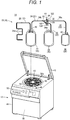
- a blood bag system 10 is set in a centrifuge/delivery apparatus 12 as illustrated in Fig. 1 by a user such as a medical worker.
- the centrifuge/delivery apparatus 12 centrifuges blood of the blood bag system 10 to generate and store a plurality of types of blood components.
- a configuration including the blood bag system 10 and the centrifuge/delivery apparatus 12 is referred to as a blood product manufacturing system 14.
- the blood bag system 10 includes a pretreatment unit (not illustrated) used for blood sampling before centrifugation and a separator unit 16 that generates blood components by centrifugation and individually stores the blood components, and the both units are connected by a relay tube 18.
- the separator unit 16 is set in the centrifuge/delivery apparatus 12 in a state where the relay tube 18 connected to the pretreatment unit is cut into the state illustrated in Fig. 1 before the centrifugation.
- the pretreatment unit of the blood bag system 10 collects whole blood from a donor (blood donor) and removes a predetermined blood component (for example, a white blood cell) from the whole blood. Therefore, the pretreatment unit includes a blood collection needle, a blood collection bag, an initial flow blood bag, a filter (for example, a white blood cell removal filter), and the like, and is configured by connecting the respective members via a plurality of tubes.
- the separator unit 16 is connected to the downstream side of the filter via the relay tube 18. Specifically, the pretreatment unit stores the first blood out of the whole blood of the donor, collected through the blood collection needle, in the initial flow blood bag, and then stores the remaining blood in the blood collection bag. Further, the pretreatment unit removes white blood cells in the filter by causing the whole blood, stored in the blood collection bag, to flow to the filter, and delivers the removed blood (white-blood-cell-removed blood) to the separator unit 16.
- the separator unit 16 of the blood bag system 10 includes a plurality of bags 20 (a blood bag 22, a PPP bag 24, and a liquid medicine bag 26), and is configured by connecting the respective bags 20 via a plurality of tubes 30.
- the blood bag 22 (first bag) is directly connected to the relay tube 18 connected to the pretreatment unit in a state of the blood bag system 10 provided as a product. Therefore, the blood bag 22 stores the removed blood delivered from the filter during blood sampling.
- the blood bag 22 is set in the centrifuge/delivery apparatus 12, and a centrifugal force is applied by the operation of the centrifuge/delivery apparatus 12.
- the removed blood in the blood bag 22 is centrifuged into blood components (platelet poor plasma (PPP), red blood cells (RBC)) and the like having different specific gravities.
- PPP platelet poor plasma
- RBC red blood cells
- the PPP bag 24 (second bag) stores PPP by receiving the PPP supplied from the blood bag 22.
- the liquid medicine bag 26 (third bag) contains a red blood cell preservation solution (additive solution), such as a MAP solution, an SAGM solution, and OPTISOL, in advance.
- a segment tube 28 is formed before the separator unit 16 is set in the centrifuge/delivery apparatus 12.
- the segment tube 28 has a plurality of sealed tubes 28a in which blood of the donor (removed blood) exists.
- the plurality of sealed tubes 28a are formed so as to be continuous in series by cutting the relay tube 18, which connects the blood bag 22 and the pretreatment unit (filter), near the filter and further sealing the cut tube at predetermined intervals.
- the segment tube 28 is cut by a user as necessary, and is used for checking blood or the like.
- the plurality of tubes 30 of the separator unit 16 branch into a plurality of tubes via a branching connector 32 (Y-type connector) as a branching section.
- the plurality of tubes 30 include a first tube 34 connecting the blood bag 22 and the branching connector 32, a second tube 36 connecting the PPP bag 24 and the branching connector 32, and a third tube 38 connecting the liquid medicine bag 26 and the branching connector 32.
- the first tube 34 has a first flow channel 34a
- the second tube 36 has a second flow channel 36a
- the third tube 38 has a third flow channel 38a.
- Each of the first tube 34, the second tube 36, and the third tube 38 has flexibility.
- the first flow channel 34a, the second flow channel 36a, and the third flow channel 38a communicate with each other via a flow channel in the branching connector 32.
- a breakable sealing member 40 click tip
- a breakable sealing member 42 is provided at an end of the third tube 38 on the liquid medicine bag 26 side.
- the sealing members 40 and 42 block the first flow channel 34a and the third flow channel 38a until a breaking operation is performed, and prevent a liquid in the blood bag 22 and the liquid medicine bag 26 from being delivered to the other bag 20.
- the separator unit 16 includes a clamp 43 that closes at least the respective flow channels (the second flow channel 36a and the third flow channel 38a) of the second tube 36 and the third tube 38.
- a configuration of the clamp 43 will be described later.
- the centrifuge/delivery apparatus 12 in which the separator unit 16 of the blood bag system 10 is set includes a box-shaped base body 44, a lid 46 capable of opening and closing an upper surface of the base body 44, and a centrifugal drum 48 provided on the base body 44.
- the base body 44 of the centrifuge/delivery apparatus 12 is provided with a motor (not illustrated) that rotates the centrifugal drum 48, a control unit 50 that controls the operation of the centrifuge/delivery apparatus 12, and an operation display unit 52 configured to allow the user to perform confirmation and operation.
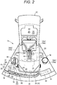
- the centrifugal drum 48 has a plurality of (six) unit set areas 54 in which the separator unit 16 can be set.
- a height of one unit set area 54 is longer than a longitudinal length of the bag 20, and is set in a range of 60° with respect to a rotation center of the centrifugal drum 48. That is, the six unit set areas 54 are arrayed without a gap along the circumferential direction to form the centrifugal drum 48 which is an annular structure.
- the unit set area 54 applies the centrifugal force to the blood bag 22 as the centrifugal drum 48 rotates.
- the unit set area 54 includes a blood bag pocket 56 accommodating the blood bag 22, a PPP bag pocket 58 accommodating a PPP bag 24, and a liquid medicine bag pocket 60 accommodating the liquid medicine bag 26 at radially outer positions of the centrifugal drum 48.
- the blood bag pocket 56 is provided at the circumferential center of the unit set area 54 and has a larger volume than the PPP bag pocket 58 or the liquid medicine bag pocket 60.
- the PPP bag pocket 58 and the liquid medicine bag pocket 60 are provided side by side in the circumferential direction on the radially outer side of the blood bag pocket 56.
- an upper surface 54a of the unit set area 54 is configured such that the plurality of tubes 30 of the blood bag system 10 are arranged and held thereon.
- the first tube 34 and a part of the segment tube 28 are arranged in a central region 54a1 (first region) on the radially inner side of the blood bag pocket 56 on the upper surface 54a.
- the central region 54a1 is provided with a lid body 62 that opens and closes an opening of the blood bag pocket 56.
- a sensor 66 optical sensor, which detects a part of a breaking section 64 that breaks the sealing member 40 and a state of blood flowing through the first tube 34, is provided at an arrangement position of the first tube 34 closed by the lid body 62.
- a part of the first tube 34 passing through the central region 54a1, the branching connector 32, a part of the second tube 36, and a part of the third tube 38 are arranged in a left region 54a2 (second region) of the upper surface 54a.
- a holder 68 that holds the branching connector 32 is provided in the left region 54a2.
- a part of the segment tube 28 passing through the central region 54a1 is arranged in a right region 54a3 (third region) of the upper surface 54a.
- a segment pocket 74 that accommodates the plurality of sealed tubes 28a of the segment tube 28 is provided.
- a tube holding section 76 protruding upward from the upper surface 54a is provided on the radially outer side of the PPP bag pocket 58 and the liquid medicine bag pocket 60 of the unit set area 54.
- the tube holding section 76 has an outer wall 78 continuous with an outer peripheral edge of the unit set area 54 and an inner wall 80 protruding from the outer peripheral edge to the inner side of the outer wall 78, and the second tube 36 is arranged between the outer wall 78 and the inner wall 80.
- the inner wall 80 extends from the left side of the liquid medicine bag pocket 60 to a circumferential intermediate position of the PPP bag pocket 58, and guides the second tube 36 to the PPP bag pocket 58.
- the unit set area 54 includes a slider 82 (pusher), which presses the blood bag 22 after centrifugation, on the radially inner side of the blood bag pocket 56.
- the slider 82 moves forward and backward along the radial direction of the centrifugal drum 48 under the control of the control unit 50 (see Fig. 1 ).
- the blood bag 22 storing the removed blood, the empty PPP bag 24, and the liquid medicine bag 26 storing the red blood cell preservation solution are accommodated in the blood bag pocket 56, the PPP bag pocket 58, and the liquid medicine bag pocket 60, respectively, by the user.
- the unit set area 54 centrifuges the removed blood in the blood bag 22 by the rotation of the centrifugal drum 48 and advances the slider 82 after the centrifugation to press the blood bag 22.
- the PPP generated by the centrifugation in the blood bag 22 is delivered to the PPP bag 24, and RBC remains in the blood bag 22 after delivering the PPP.
- the blood bag system 10 is taken out from the centrifuge/delivery apparatus 12 by the user, and the liquid medicine bag 26 is suspended from a stand (not illustrated).
- the red blood cell preservation solution is supplied from the liquid medicine bag 26 to the blood bag 22, and the blood bag 22 is turned into a state of storing the RBC (blood products) containing a liquid medicine.
- the clamp 43 of the blood bag system 10 includes: a base 92 formed with insertion holes 90 through which the second tube 36 and the third tube 38 are inserted; and an operation section 94 which is provided on the base 92 and can be operated by a finger. That is, the clamp 43 is provided on the second tube 36 and the third tube 38.
- the base 92 is formed in a rectangular plate shape using a hard resin material. That is, the base 92 includes a first long side 96a and a second long side 96b extending in parallel with each other, and a first short side 98a and a second short side 98b extending in parallel with each other.
- the insertion holes 90 include a first insertion hole 100 through which the second tube 36 is inserted and a second insertion hole 102 through which the third tube 38 is inserted.
- a diameter of the first insertion hole 100 is formed to be equal to or larger than an outer diameter of the second tube 36.
- a diameter of the second insertion hole 102 is formed to be equal to or larger than an outer diameter of the third tube 38.
- the first insertion hole 100 and the second insertion hole 102 are arranged along the longitudinal direction of the base 92.
- the first insertion hole 100 and the second insertion hole 102 are separated from each other by a wall section of the base 92.
- a wall section forming the first insertion hole 100 is provided with a first slit 104 for pressing an outer circumferential surface of the second tube 36 inward such that the second flow channel 36a of the second tube 36 is closed.
- the first slit 104 extends from the first insertion hole 100 toward the side opposite to the second insertion hole 102 (first short side 98a).
- the first slit 104 linearly extends along the longitudinal direction of the base 92 (a direction in which the first insertion hole 100 and the second insertion hole 102 are arrayed).
- the first slit 104 is formed to be narrower in the extending direction.
- a width dimension of an end of the first slit 104 on the first insertion hole 100 side (the maximum width dimension of the first slit 104) is smaller than the outer diameter of the second tube 36.
- An extension length of the first slit 104 is equal to or longer than the outer diameter of the second tube 36.
- a wall section forming the second insertion hole 102 is provided with a second slit 106 for pressing an outer circumferential surface of the third tube 38 inward such that the third flow channel 38a of the third tube 38 is closed.
- the second slit 106 extends from the second insertion hole 102 toward the first insertion hole 100.
- the second slit 106 linearly extends along the longitudinal direction of the base 92 (the direction in which the first insertion hole 100 and the second insertion hole 102 are arrayed).
- the extending direction of the second slit 106 from the second insertion hole 102 is substantially the same as the extending direction of the first slit 104 from the first insertion hole 100.
- the second slit 106 is formed to be narrower in the extending direction.
- a width dimension of an end of the second slit 106 on the second insertion hole 102 side (the maximum width dimension of the second slit 106) is smaller than the outer diameter of the third tube 38.
- An extension length of the second slit 106 is equal to or longer than the outer diameter of the third tube 38.
- the second slit 106 is formed such that the third tube 38 can return from the second slit 106 to the second insertion hole 102. That is, the second slit 106 is formed such that the third flow channel 38a of the third tube 38 can be opened as the third tube 38 returns from the second slit 106 to the second insertion hole 102.
- the operation section 94 is provided at an end (the second short side 98b) of the base 92 in a direction opposite to the extending direction of the first slit 104 and the second slit 106. Specifically, the operation section 94 is provided at an end of the second short side 98b where the second long side 96b is located. In other words, the operation section 94 is located closer to the second long side 92b than the center of the base 96 in the lateral direction.
- the operation section 94 includes a flat plate portion 108 and an anti-slip portion 110 provided on at least one plane of the flat plate portion 108.
- the flat plate portion 108 extends from the second short side 92b of the base 98 to a side opposite to the first insertion hole 100 and the second insertion hole 102.
- the anti-slip portion 110 has a plurality of protrusions 112 arranged along the longitudinal direction of the base 92. Each of the protrusions 112 extends along the lateral direction of the base 92.
- the anti-slip portion 110 is not limited to the example having the plurality of protrusions 112, and may have any configuration as long as slipping of the finger with respect to the operation section 94 can be suppressed.
- the clamp 43 is provided on the second tube 36 and the third tube 38 such that the second long side 96b (operation section 94) is located above the first long side 96a in a state where the blood bag system 10 is set in the centrifuge/delivery apparatus 12.
- the blood bag system 10 is basically configured as described above, and operations thereof will be described hereinafter.
- the blood bag system 10 stores the removed blood obtained by removing the predetermined component (white blood cell) from the whole blood of the donor in the blood bag 22, as the user (medical worker) uses the pretreatment unit during blood sampling.
- the blood bag 22 stores blood of an appropriate blood volume (for example, 400 cc) depending on the donor.
- the user separates the separator unit 16 of the blood bag system 10 from the pretreatment unit and sets the separator unit 16 in the centrifuge/delivery apparatus 12 in order to centrifuge the removed blood.
- the blood bag 22 is inserted into the blood bag pocket 56 of the unit set area 54.
- the first tube 34 is arranged in the central region 54a1 of the upper surface 54a.
- the liquid medicine bag 26 is inserted into the liquid medicine bag pocket 60, and the PPP bag 24 is inserted into the PPP bag pocket 58.
- the branching connector 32 is set in the holder 68, and the clamp 43 is arranged in the vicinity of the holder 68 in the left region 54a2 of the upper surface 54a. Then, when the user closes the lid body 62, the breaking section 64 reliably breaks the sealing member 40 to open the first flow channel 34a of the first tube 34.
- the centrifuge/delivery apparatus 12 rotates the centrifugal drum 48 under the control of the control unit 50 to centrifuge the removed blood in the blood bag 22 into the blood components having different specific gravities (PPP, RBC, and the like). After such centrifugation, the centrifuge/delivery apparatus 12 presses the blood bag 22 by the slider 82. As a result, PPP having a light specific gravity flows out from the blood bag 22, and the PPP flows through the first tube 34, the branching connector 32, and the second tube 36 in this order and flows into the PPP bag 24.
- the centrifuge/delivery apparatus 12 retracts the slider 82 such that the blood bag 22 can be taken out from the blood bag pocket 56. Then, the user closes each of the second flow channel 36a of the second tube 36 and the third flow channel 38a of the third tube 38 by the clamp 43.
- the user holds the operation section 94 with a finger and pulls the operation section 94 such that the base 92 moves toward the operation section 94 with respect to the second tube 36 and the third tube 38. Then, the second tube 36 inserted through the first insertion hole 100 is inserted into the first slit 104, and the third tube 38 inserted through the second insertion hole 102 is inserted into the second slit 106, as illustrated in Fig. 3B .
- the second tube 36 When the second tube 36 is inserted into the first slit 104, the second tube 36 is pressed radially inward by the wall section forming the first slit 104 to be compressed and deformed into a flat shape, and thus, the second flow channel 36a of the second tube 36 is closed.
- the third tube 38 When the third tube 38 is inserted into the second slit 106, the third tube 38 is pressed radially inward by the wall section forming the second slit 106 to be compressed and deformed into a flat shape, and thus, the third flow channel 38a of the third tube 38 is closed.
- the user takes out the blood bag system 10 from the centrifuge/delivery apparatus 12, and suspends the liquid medicine bag 26 on the stand (not illustrated) as illustrated in Fig. 4 .
- the third tube 38 is moved from the second slit 106 to the second insertion hole 102. That is, the third flow channel 38a of the third tube 38 is opened.
- the red blood cell preservation solution in the liquid medicine bag 26 is supplied to the blood bag 22 through the third tube 38, the branching connector 32, and the first tube 34 by the action of gravity.
- the second tube 36 remains located in the first slit 104. That is, the second flow channel 36a of the second tube 36 is maintained in the closed state. Therefore, the red blood cell preservation solution is prevented from flowing into the PPP bag 24.
- the RBC containing the red blood cell preservation solution is stored in the blood bag 22.
- the blood bag system 10 and the clamp 43 according to the present embodiment have the following effects.
- the blood bag system 10 includes: the first bag (blood bag 22) for containing blood, the second bag (PPP bag 24) for containing a blood component obtained by centrifuging the blood in the first bag (blood bag 22), and the third bag (liquid medicine bag 26) for containing the additive solution.
- the first tube 34 connected to the first bag (blood bag 22) is connected to the second tube 36 connected to the second bag (PPP bag 24) and the third tube 38 connected to the third bag (liquid medicine bag 26) via the branching section (branching connector 32).
- the blood bag system 10 includes the single clamp 43 capable of closing the respective flow channels (the second flow channel 36a and the third flow channel 38a) of the second tube 36 and the third tube 38.
- the clamp 43 includes the base 92 formed with the insertion hole 90 through which the second tube 36 and the third tube 38 are inserted.
- the wall section forming the insertion hole 90 is provided with the first slit 104 for pressing the outer circumferential surface of the second tube 36 inward such that the flow channel (second flow channel 36a) of the second tube 36 is closed, and the second slit 106 for pressing the outer circumferential surface of the third tube 38 inward such that the flow channel (third flow channel 38a) of the third tube 38 is closed.
- the second tube 36 and the third tube 38 are inserted into the insertion hole 90 formed in the base 92, and the first slit 104 and the second slit 106 are provided in the wall section forming the insertion hole 90.
- the respective flow channels (the second flow channel 36a and the third flow channel 38a) of the second tube 36 and the third tube 38 can be efficiently closed by the single clamp 43.
- the second slit 106 is formed such that the flow channel (third flow channel 38a) of the third tube 38 can be opened as the third tube 38 returns from the second slit 106 to the insertion hole 90.
- the flow channel (third flow channel 38a) of the third tube 38 can be easily closed and opened.
- the insertion holes 90 include the first insertion hole 100 through which the second tube 36 is inserted and the second insertion hole 102 through which the third tube 38 is inserted.
- the first slit 104 is provided in the wall section forming the first insertion hole 100
- the second slit 106 is provided in the wall section forming the second insertion hole 102.
- the second tube 36 and the third tube 38 can be easily inserted into the first slit 104 and the second slit 106, respectively.
- the first slit 104 and the second slit 106 are formed to cause the base 92 to slide in one direction with respect to the second tube 36 and the third tube 38 such that the second tube 36 is inserted into the first slit 104 and the third tube 38 is inserted into the second slit 106.
- the respective flow channels (the second flow channel 36a and the third flow channel 38a) of the second tube 36 and the third tube 38 can be efficiently closed.
- the extending direction of the first slit 104 from the first insertion hole 100 is substantially the same as the extending direction of the second slit 106 from the second insertion hole 102.
- the second tube 36 and the third tube 38 can be easily inserted into the first slit 104 and the second slit 106, respectively, by causing the base 92 to slide in one direction with respect to the second tube 36 and the third tube 38.
- Each of the first slit 104 and the second slit 106 extends along the direction in which the first insertion hole 100 and the second insertion hole 102 are arrayed.
- the second tube 36 and the third tube 38 can be inserted into the first slit 104 and the second slit 106, respectively, by causing the base 92 to slide along the array direction of the first insertion hole 100 and the second insertion hole 102.
- the clamp 43 includes the operation section 94 which is provided at the end of the base 92 in a direction opposite to the extending direction of the first slit 104 and the second slit 106 and can be operated by a finger.
- the sliding operation of the base 92 can be easily performed.
- the operation section 94 includes the flat plate portion 108.
- the sliding operation of the base 92 can be easily performed.
- the clamp 43 may include first slits 104a to 104e according to first to fifth configuration examples, which will be described hereinafter, for preventing the second tube 36 from returning from the first slit 104 to the first insertion hole 100, instead of the first slit 104.
- the first slit 104a includes a holding slit 120 that holds the second tube 36 and an intermediate slit 122 located between the holding slit 120 and the first insertion hole 100.
- the intermediate slit 122 linearly extends from the first insertion hole 100 toward the first short side 98a.
- the holding slit 120 linearly extends from an extending end of the intermediate slit 122 toward the first short side 98a.
- a slit width of the intermediate slit 122 is set to be the same as a slit width of the holding slit 120.
- the first slit 104a includes the holding slit 120 that holds the second tube 36 and the intermediate slit 122 located between the holding slit 120 and the first insertion hole 100, and the slit width of the intermediate slit 122 is substantially the same as the slit width of the holding slit 120. Therefore, the flow channel (second flow channel 36a) of the second tube 36 can be maintained in a closed state with a simple configuration.
- the first slit 104b according to the second configuration example includes an intermediate slit 124, instead of the intermediate slit 122 of the first slit 104a according to the first configuration example described above.
- a slit width of the intermediate slit 124 is narrower than the slit width of the holding slit 120.
- the slit width of the intermediate slit 124 is smaller than the slit width of the holding slit 120. Therefore, it is possible to effectively prevent the second tube 36 from returning from the holding slit 120 to the first insertion hole 100.
- the first slit 104c according to the third configuration example includes an intermediate slit 126, instead of the intermediate slit 122 of the first slit 104a according to the first configuration example described above.
- the intermediate slit 126 extends to be bent (curved). In other words, the intermediate slit 126 extends in a curve shape (arc shape).
- the intermediate slit 126 extends to be bent. Therefore, it is possible to effectively prevent the second tube 36 from returning from the holding slit 120 to the first insertion hole 100.
- the first slit 104d according to the fourth configuration example includes an intermediate slit 128, instead of the intermediate slit 122 of the first slit 104a according to the first configuration example described above.
- Wall sections 129a and 129b forming the intermediate slit 128 (the first slit 104d) are provided with a return-preventing section 130 that prevents the second tube 36 from returning from the holding slit 120 to the first insertion hole 100.
- the return-preventing section 130 has protrusions 132a and 132b which are respectively provided on the wall sections 129a and 129b facing each other and forming the intermediate slit 128.
- the protrusions 132a and 132b are located on the holding slit 120 side in the intermediate slit 128.
- the protrusion 132a protrudes from one wall section 129a toward the other wall section 129b.
- the protrusion 132b protrudes from the other wall section 129b toward the one wall section 129a.
- the protrusion 132a and the protrusion 132b face each other.
- the protrusion 132a is formed in a tapered triangular shape.
- the protrusion 132a is provided with an inclined portion 134 located on the first insertion hole 100 side and a stopper portion 136 located on the holding slit 120 side.
- the inclined portion 134 is inclined toward a side where the first insertion hole 100 is located toward a protruding end of the protrusion 132a.
- the stopper portion 136 extends substantially perpendicularly to the extending direction of the holding slit 120.
- the protrusion 132b is configured similarly to the protrusion 132a. Therefore, a configuration of the protrusion 132b will not be described.
- the second tube 36 can move from the first insertion hole 100 to the holding slit 120 over the inclined portions 134 of the protrusions 132a and 132b via the intermediate slit 128.
- the wall sections 129a and 129b forming the first slit 104d are provided with the return-preventing section 130 that prevents the second tube 36 from returning from the first slit 104d to the first insertion hole 100. Therefore, it is possible to more effectively prevent the second tube 36 from returning from the first slit 104d (holding slit 120) to the first insertion hole 100.
- the stopper portion 136 may be inclined to the side opposite to the first insertion hole 100 toward the protruding end of the protrusion 132a.
- Shapes of the protrusions 132a and 132b are not limited to the tapered triangular shape.
- the protrusions 132a and 132b may be formed in a semicircular shape.
- the protrusions 132a and 132b may be located on the first insertion hole 100 side of the intermediate slit 128.
- the return-preventing section 130 may have only one of the protrusion 132a and the protrusion 132b and omit the other.
- the first slit 104e according to the fifth configuration example includes the holding slit 120 of the first slit 104a according to the first configuration example described above. Note that the first slit 104e does not include the intermediate slit 122 described above.
- the wall sections 141a and 141b forming the first slit 104e are provided with a return-preventing section 140 that prevents the second tube 36 from returning from the first slits 104e to the first insertion holes 100.
- the return-preventing section 140 has protrusions 142a and 142b which are respectively provided on the wall sections 141a and 141b facing each other and forming the first slit 104e.
- the protrusions 142a and 142b are located at an end of the first slit 104e on the first insertion hole 100 side.
- the protrusion 142a protrudes from one wall section 141a toward the other wall section 141b.
- the protrusion 142b protrudes from the other wall section 141b toward the one wall section 141a.
- the protrusion 142a and the protrusion 142b face each other.
- the protrusions 142a and 142b are formed in a semicircular shape.
- the first slit 104e has the same effect as the first slit 104d according to the fourth configuration example described above.
- a dimension in the longitudinal direction of the clamp 43 can be made relatively short since the first slit 104e does not have the intermediate slit 122 described above.
- a clamp 43A according to a first modification will be described. Note that the same components as those of the clamp 43 described above are denoted by the same reference signs in the clamp 43A according to the present modification, and the description thereof will be omitted. The same applies to a clamp 43B according to a second modification and a clamp 43C according to a third modification which will be described later.
- the clamp 43A according to the first modification includes a first slit 150 and a second slit 152, instead of the first slit 104 and the second slit 106 of the clamp 43 described above.
- the first slit 150 is different from the first slit 104 only in terms of an extending direction from the first insertion hole 100. That is, the first slit 150 extends so as to be inclined to the first long side 96a side from the first insertion hole 100 toward the first short side 98a.
- the second slit 152 is different from the second slit 106 only in terms of an extending direction from the second insertion hole 102. That is, the second slit 152 extends so as to be inclined to the first long side 96a side from the second insertion hole 102 toward the first short side 98a.
- a user lifts the operation section 94 obliquely upward in the state of being held by a finger such that the second tube 36 located in the first insertion hole 100 can be easily inserted into the first slit 150 and the third tube 38 located in the second insertion hole 102 can be easily inserted into the second slit 152.
- shapes of the first slits 104a to 104e according to the first to fifth configuration examples described above may be adopted.
- the clamp 43B has a rectangular base 154 and an operation section 156 provided on one long side of the base 154.
- the base 154 is formed with the insertion holes 90 (first insertion hole 100 and second insertion hole 102).
- a wall section forming the first insertion hole 100 is provided with a first slit 158, and a wall section forming the second insertion hole 102 is provided with a second slit 160.
- Each of the first slit 158 and the second slit 160 extends along a direction (lateral direction of the base 154) orthogonal to an array direction of the first insertion hole 100 and the second insertion hole 102.
- the first slit 158 extends from the first insertion hole 100 toward the other long side (side opposite to the operation section 156).
- a shape of the first slit 158 is similar to the shape of the first slit 104 described above.
- the second slit 160 extends from the second insertion hole 102 toward the other long side (side opposite to the operation section 156).
- a shape of the second slit 160 is the same as the shape of the second slit 106 described above.
- the operation section 156 includes a flat plate portion 162 (support section) extending from one long side of the base 154 in a direction opposite to the base 154, and a hook portion 164 provided at an extending end of the flat plate portion 162.
- the hook portion 164 is configured to allow a user to hook a finger thereon, and is curved in an arc shape from the extending end of the flat plate portion 162 to one surface side of the base 154.
- the hook portion 164 is located closer to the second insertion hole 102 than the center of the base 154 in the longitudinal direction. However, a position of the hook portion 164 in the longitudinal direction of the base 154 can be arbitrarily set.
- each of the first slit 158 and the second slit 160 extends along the direction orthogonal to the array direction of the first insertion hole 100 and the second insertion hole 102.
- the second tube 36 located in the first insertion hole 100 can be easily inserted into the first slit 158, and the third tube 38 located in the second insertion hole 102 can be easily inserted into the second slit 160.
- the operation section 156 includes the hook portion 164 for hooking the finger. According to such a configuration, a sliding operation of the base 154 can be easily performed.
- the clamp 43B may include an operation section 156a instead of the operation section 156.
- the operation section 156a includes a flat plate portion 168 formed with a hole 166 into which the user's finger can be inserted.
- the hole 166 is located substantially at the center of the base 154 in the longitudinal direction. However, a position of the hole 166 with respect to the longitudinal direction of the base 154 can be arbitrarily set. In such a case where the hole 166 is provided in the flat plate portion 168, the same effect as that of the hook portion 164 is obtained.
- the shapes of the first slits 104a to 104e according to the first to fifth configuration examples described above may be adopted.
- the clamp 43C includes a base 172 formed with one insertion hole 170 through which both the second tube 36 and the third tube 38 are inserted.
- the base 172 is formed in a rectangular plate shape using a hard resin material. That is, the base 172 includes a first long side 174a and a second long side 174b extending in parallel with each other, and a first short side 176a and a second short side 176b extending in parallel with each other.
- the insertion hole 170 is located at the center of the base 172 and extends in the longitudinal direction of the base 172.
- a first slit 180 for pressing the outer circumferential surface of the second tube 36 inward so as to close the second flow channel 36a of the second tube 36 is provided at one end (end on the first short side 176a side) of the base 172.
- the first slit 180 linearly extends from the insertion hole 170 toward the first short side 176a.
- a slit width of the first slit 180 is smaller than the outer diameter of the second tube 36.
- the first slit 180 is provided substantially at the center of one end of the base 172 in the lateral direction.
- a second slit 182 for pressing the outer circumferential surface of the third tube 38 inward so as to close the third flow channel 38a of the third tube 38 is provided at the other end (end on the second short side 176b side) of the base 172.
- the second slit 182 linearly extends from the insertion hole 170 toward the second short side 176b. That is, the first slit 180 and the second slit 182 extend in directions opposite to each other from the insertion hole 170.
- a slit width of the second slit 182 is smaller than the outer diameter of the third tube 38.
- the second slit 182 is provided substantially at the center of the other end of the base 172 in the lateral direction.
- a wall section forming the insertion hole 170 is provided with a first guide portion 171a that guides the second tube 36 to the first slit 180 and a second guide portion 171b that guides the third tube 38 to the second slit 182.
- the first guide portion 171a is formed such that one end of the insertion hole 170 (end on the first short side 176a side) becomes narrower toward the first slit 180.
- the second guide portion 171b is formed such that the other end of the insertion hole 170 (end of the second short side 176b) becomes narrower toward the second slit 182.
- the insertion hole 170 is one hole into which both the second tube 36 and the third tube 38 are inserted.
- the configuration of the clamp 43C can be simplified.
- the first slit 180 and the second slit 182 extend in the opposite directions from the insertion hole 170.
- the second tube 36 and the third tube 38 can be easily inserted into the first slit 180 and the second slit 182, respectively.
- the shapes of the first slits 104a to 104e according to the first to fifth configuration examples described above may be adopted.
Landscapes
- Health & Medical Sciences (AREA)
- Heart & Thoracic Surgery (AREA)
- Hematology (AREA)
- Engineering & Computer Science (AREA)
- Anesthesiology (AREA)
- Biomedical Technology (AREA)
- Life Sciences & Earth Sciences (AREA)
- Animal Behavior & Ethology (AREA)
- General Health & Medical Sciences (AREA)
- Public Health (AREA)
- Veterinary Medicine (AREA)
- Vascular Medicine (AREA)
- Pulmonology (AREA)
- External Artificial Organs (AREA)
- Infusion, Injection, And Reservoir Apparatuses (AREA)
Abstract
Description
- The present invention relates to a blood bag system and a clamp.
- For example,
JP 2016-106012 A - A first tube connected to the first bag is connected to a second tube connected to the second bag and a third tube connected to the third bag via a branching section.
- In the above-described blood bag system, the blood bag system is set in a centrifuge/delivery apparatus to centrifuge the blood in the first bag. Then, a blood component obtained by centrifugation is delivered from the first bag to the second bag via the first tube and the second tube. Thereafter, the blood bag system is removed from the centrifuge/delivery apparatus in a state where a flow channel of the second tube is closed by a first clamp and a flow channel of the third tube is closed by a second clamp. Subsequently, the third bag is suspended from a suspension stand, the second clamp is removed from the third tube, and the additive solution, such as a red blood cell preservation solution, is delivered to the first bag via the third tube and the first tube.
- In this manner, when the first clamp for closing the flow channel of the second tube and the second clamp for closing the flow channel of the third tube are separate parts, there is a possibility that it is difficult to efficiently close the respective flow channels of the two tubes (the second tube and the third tube).
- The present invention has been made in view of such problems, and aims to provide a blood bag system and a clamp capable of efficiently closing the respective flow channels of two tubes by one clamp.
- An aspect of the present invention is a blood bag system including: a first bag for containing blood; a second bag for containing a blood component obtained by centrifuging the blood in the first bag; a third bag for containing an additive solution; and one clamp capable of closing respective flow channels of a second tube and a third tube. A first tube connected to the first bag is connected to the second tube connected to the second bag and the third tube connected to the third bag via a branching section. The clamp includes a base formed with an insertion hole through which the second tube and the third tube are inserted. A wall section forming the insertion hole is provided with: a first slit for pressing an outer circumferential surface of the second tube inward so as to close the flow channel of the second tube; and a second slit for pressing an outer circumferential surface of the third tube inward so as to close the flow channel of the third tube.
- Another aspect of the present invention is a clamp capable of closing respective flow channels of a second tube and a third tube in a blood bag system which includes: a first bag for containing blood; a second bag for containing a blood component obtained by centrifuging the blood in the first bag; a third bag containing an additive solution; a first tube having one end connected to the first bag and another end connected to a branching section; the second tube connecting the branching section and the second bag; and the third tube connecting the branching section and the third bag. The clamp includes a base formed with an insertion hole through which the second tube and the third tube are inserted. A wall section forming the insertion hole is provided with: a first slit for pressing an outer circumferential surface of the second tube inward so as to close the flow channel of the second tube; and a second slit for pressing an outer circumferential surface of the third tube inward so as to close the flow channel of the third tube.
- According to the present invention, the second tube and the third tube are inserted into the insertion hole formed in the base, and the first slit and the second slit are provided in the wall section forming the insertion hole. Thus, the respective flow channels of the second tube and the third tube can be efficiently closed by the single clamp.
-
-
Fig. 1 is an explanatory view illustrating an overall configuration of a blood bag system and a centrifuge/delivery apparatus according to an embodiment of the present invention. -
Fig. 2 is a plan view illustrating a unit set area of the centrifuge/delivery apparatus. -
Fig. 3A is a perspective explanatory view of a clamp ofFig. 1 , andFig. 3B is a plan explanatory view of the clamp ofFig. 1 . -
Fig. 4 is an explanatory view of a procedure for delivering a red blood cell preservation solution from a liquid medicine bag to a blood bag. -
Fig. 5A is an explanatory plan view of a first slit according to a first configuration example,Fig. 5B is an explanatory plan view of a first slit according to a second configuration example, andFig. 5C is an explanatory plan view of a first slit according to a third configuration example. -
Fig. 6A is an explanatory plan view of a first slit according to a fourth configuration example, andFig. 6B is an explanatory plan view of a first slit according to a fifth configuration example. -
Fig. 7 is an explanatory plan view of a clamp according to a first modification. -
Fig. 8A is a perspective explanatory view of a clamp according to a second modification,Fig. 8B is a plan explanatory view of the clamp ofFig. 8A, and Fig. 8C is an explanatory view of a configuration example of an operation section forming the clamp ofFig. 8A . -
Fig. 9 is an explanatory plan view of a clamp according to a third modification. - Hereinafter, preferred embodiments of the present invention will be described in detail with reference to the accompanying drawings.
- A
blood bag system 10 according to an embodiment of the present invention is set in a centrifuge/delivery apparatus 12 as illustrated inFig. 1 by a user such as a medical worker. The centrifuge/delivery apparatus 12 centrifuges blood of theblood bag system 10 to generate and store a plurality of types of blood components. Hereinafter, a configuration including theblood bag system 10 and the centrifuge/delivery apparatus 12 is referred to as a bloodproduct manufacturing system 14. - The
blood bag system 10 includes a pretreatment unit (not illustrated) used for blood sampling before centrifugation and aseparator unit 16 that generates blood components by centrifugation and individually stores the blood components, and the both units are connected by arelay tube 18. Theseparator unit 16 is set in the centrifuge/delivery apparatus 12 in a state where therelay tube 18 connected to the pretreatment unit is cut into the state illustrated inFig. 1 before the centrifugation. - The pretreatment unit of the
blood bag system 10 collects whole blood from a donor (blood donor) and removes a predetermined blood component (for example, a white blood cell) from the whole blood. Therefore, the pretreatment unit includes a blood collection needle, a blood collection bag, an initial flow blood bag, a filter (for example, a white blood cell removal filter), and the like, and is configured by connecting the respective members via a plurality of tubes. Theseparator unit 16 is connected to the downstream side of the filter via therelay tube 18. Specifically, the pretreatment unit stores the first blood out of the whole blood of the donor, collected through the blood collection needle, in the initial flow blood bag, and then stores the remaining blood in the blood collection bag. Further, the pretreatment unit removes white blood cells in the filter by causing the whole blood, stored in the blood collection bag, to flow to the filter, and delivers the removed blood (white-blood-cell-removed blood) to theseparator unit 16. - On the other hand, the
separator unit 16 of theblood bag system 10 includes a plurality of bags 20 (ablood bag 22, aPPP bag 24, and a liquid medicine bag 26), and is configured by connecting therespective bags 20 via a plurality oftubes 30. - The blood bag 22 (first bag) is directly connected to the
relay tube 18 connected to the pretreatment unit in a state of theblood bag system 10 provided as a product. Therefore, theblood bag 22 stores the removed blood delivered from the filter during blood sampling. Theblood bag 22 is set in the centrifuge/delivery apparatus 12, and a centrifugal force is applied by the operation of the centrifuge/delivery apparatus 12. As a result, the removed blood in theblood bag 22 is centrifuged into blood components (platelet poor plasma (PPP), red blood cells (RBC)) and the like having different specific gravities. Then, theblood bag 22 delivers PPP under the operation of the centrifuge/delivery apparatus 12 after centrifugation to store only the remaining RBC. - The PPP bag 24 (second bag) stores PPP by receiving the PPP supplied from the
blood bag 22. On the other hand, the liquid medicine bag 26 (third bag) contains a red blood cell preservation solution (additive solution), such as a MAP solution, an SAGM solution, and OPTISOL, in advance. - In addition, a
segment tube 28 is formed before theseparator unit 16 is set in the centrifuge/delivery apparatus 12. Thesegment tube 28 has a plurality ofsealed tubes 28a in which blood of the donor (removed blood) exists. The plurality of sealedtubes 28a are formed so as to be continuous in series by cutting therelay tube 18, which connects theblood bag 22 and the pretreatment unit (filter), near the filter and further sealing the cut tube at predetermined intervals. Thesegment tube 28 is cut by a user as necessary, and is used for checking blood or the like. - The plurality of
tubes 30 of theseparator unit 16 branch into a plurality of tubes via a branching connector 32 (Y-type connector) as a branching section. Specifically, the plurality oftubes 30 include afirst tube 34 connecting theblood bag 22 and the branchingconnector 32, asecond tube 36 connecting thePPP bag 24 and the branchingconnector 32, and athird tube 38 connecting theliquid medicine bag 26 and the branchingconnector 32. Thefirst tube 34 has afirst flow channel 34a, thesecond tube 36 has asecond flow channel 36a, and thethird tube 38 has athird flow channel 38a. Each of thefirst tube 34, thesecond tube 36, and thethird tube 38 has flexibility. Thefirst flow channel 34a, thesecond flow channel 36a, and thethird flow channel 38a communicate with each other via a flow channel in the branchingconnector 32. - A breakable sealing member 40 (click tip) is provided at an end of the
first tube 34 on theblood bag 22 side. Similarly, abreakable sealing member 42 is provided at an end of thethird tube 38 on theliquid medicine bag 26 side. The sealingmembers first flow channel 34a and thethird flow channel 38a until a breaking operation is performed, and prevent a liquid in theblood bag 22 and theliquid medicine bag 26 from being delivered to theother bag 20. - The
separator unit 16 includes aclamp 43 that closes at least the respective flow channels (thesecond flow channel 36a and thethird flow channel 38a) of thesecond tube 36 and thethird tube 38. A configuration of theclamp 43 will be described later. - On the other hand, the centrifuge/
delivery apparatus 12 in which theseparator unit 16 of theblood bag system 10 is set includes a box-shapedbase body 44, alid 46 capable of opening and closing an upper surface of thebase body 44, and acentrifugal drum 48 provided on thebase body 44. In addition, thebase body 44 of the centrifuge/delivery apparatus 12 is provided with a motor (not illustrated) that rotates thecentrifugal drum 48, acontrol unit 50 that controls the operation of the centrifuge/delivery apparatus 12, and anoperation display unit 52 configured to allow the user to perform confirmation and operation. - The
centrifugal drum 48 has a plurality of (six) unit setareas 54 in which theseparator unit 16 can be set. A height of one unit setarea 54 is longer than a longitudinal length of thebag 20, and is set in a range of 60° with respect to a rotation center of thecentrifugal drum 48. That is, the six unit setareas 54 are arrayed without a gap along the circumferential direction to form thecentrifugal drum 48 which is an annular structure. - As illustrated in
Figs. 1 and2 , the unit setarea 54 applies the centrifugal force to theblood bag 22 as thecentrifugal drum 48 rotates. Specifically, the unit setarea 54 includes ablood bag pocket 56 accommodating theblood bag 22, aPPP bag pocket 58 accommodating aPPP bag 24, and a liquidmedicine bag pocket 60 accommodating theliquid medicine bag 26 at radially outer positions of thecentrifugal drum 48. - The
blood bag pocket 56 is provided at the circumferential center of the unit setarea 54 and has a larger volume than thePPP bag pocket 58 or the liquidmedicine bag pocket 60. ThePPP bag pocket 58 and the liquidmedicine bag pocket 60 are provided side by side in the circumferential direction on the radially outer side of theblood bag pocket 56. - In addition, an
upper surface 54a of the unit setarea 54 is configured such that the plurality oftubes 30 of theblood bag system 10 are arranged and held thereon. Thefirst tube 34 and a part of thesegment tube 28 are arranged in a central region 54a1 (first region) on the radially inner side of theblood bag pocket 56 on theupper surface 54a. The central region 54a1 is provided with alid body 62 that opens and closes an opening of theblood bag pocket 56. Further, a sensor 66 (optical sensor), which detects a part of abreaking section 64 that breaks the sealingmember 40 and a state of blood flowing through thefirst tube 34, is provided at an arrangement position of thefirst tube 34 closed by thelid body 62. - A part of the
first tube 34 passing through the central region 54a1, the branchingconnector 32, a part of thesecond tube 36, and a part of thethird tube 38 are arranged in a left region 54a2 (second region) of theupper surface 54a. In the left region 54a2, aholder 68 that holds the branchingconnector 32 is provided. - A part of the
segment tube 28 passing through the central region 54a1 is arranged in a right region 54a3 (third region) of theupper surface 54a. In the right region 54a3, asegment pocket 74 that accommodates the plurality of sealedtubes 28a of thesegment tube 28 is provided. - Further, a
tube holding section 76 protruding upward from theupper surface 54a is provided on the radially outer side of thePPP bag pocket 58 and the liquidmedicine bag pocket 60 of the unit setarea 54. Thetube holding section 76 has anouter wall 78 continuous with an outer peripheral edge of the unit setarea 54 and aninner wall 80 protruding from the outer peripheral edge to the inner side of theouter wall 78, and thesecond tube 36 is arranged between theouter wall 78 and theinner wall 80. Theinner wall 80 extends from the left side of the liquidmedicine bag pocket 60 to a circumferential intermediate position of thePPP bag pocket 58, and guides thesecond tube 36 to thePPP bag pocket 58. - In addition, the unit set
area 54 includes a slider 82 (pusher), which presses theblood bag 22 after centrifugation, on the radially inner side of theblood bag pocket 56. Theslider 82 moves forward and backward along the radial direction of thecentrifugal drum 48 under the control of the control unit 50 (seeFig. 1 ). - In the above-described unit set
area 54, theblood bag 22 storing the removed blood, theempty PPP bag 24, and theliquid medicine bag 26 storing the red blood cell preservation solution are accommodated in theblood bag pocket 56, thePPP bag pocket 58, and the liquidmedicine bag pocket 60, respectively, by the user. Then, the unit setarea 54 centrifuges the removed blood in theblood bag 22 by the rotation of thecentrifugal drum 48 and advances theslider 82 after the centrifugation to press theblood bag 22. As a result, the PPP generated by the centrifugation in theblood bag 22 is delivered to thePPP bag 24, and RBC remains in theblood bag 22 after delivering the PPP. Thereafter, theblood bag system 10 is taken out from the centrifuge/delivery apparatus 12 by the user, and theliquid medicine bag 26 is suspended from a stand (not illustrated). As a result, the red blood cell preservation solution is supplied from theliquid medicine bag 26 to theblood bag 22, and theblood bag 22 is turned into a state of storing the RBC (blood products) containing a liquid medicine. - As illustrated in
Figs. 3A and 3B , theclamp 43 of theblood bag system 10 includes: a base 92 formed withinsertion holes 90 through which thesecond tube 36 and thethird tube 38 are inserted; and anoperation section 94 which is provided on thebase 92 and can be operated by a finger. That is, theclamp 43 is provided on thesecond tube 36 and thethird tube 38. Thebase 92 is formed in a rectangular plate shape using a hard resin material. That is, thebase 92 includes a firstlong side 96a and a secondlong side 96b extending in parallel with each other, and a firstshort side 98a and a secondshort side 98b extending in parallel with each other. - The insertion holes 90 include a
first insertion hole 100 through which thesecond tube 36 is inserted and asecond insertion hole 102 through which thethird tube 38 is inserted. A diameter of thefirst insertion hole 100 is formed to be equal to or larger than an outer diameter of thesecond tube 36. A diameter of thesecond insertion hole 102 is formed to be equal to or larger than an outer diameter of thethird tube 38. Thefirst insertion hole 100 and thesecond insertion hole 102 are arranged along the longitudinal direction of thebase 92. Thefirst insertion hole 100 and thesecond insertion hole 102 are separated from each other by a wall section of thebase 92. - A wall section forming the
first insertion hole 100 is provided with afirst slit 104 for pressing an outer circumferential surface of thesecond tube 36 inward such that thesecond flow channel 36a of thesecond tube 36 is closed. Thefirst slit 104 extends from thefirst insertion hole 100 toward the side opposite to the second insertion hole 102 (firstshort side 98a). Thefirst slit 104 linearly extends along the longitudinal direction of the base 92 (a direction in which thefirst insertion hole 100 and thesecond insertion hole 102 are arrayed). - The
first slit 104 is formed to be narrower in the extending direction. A width dimension of an end of thefirst slit 104 on thefirst insertion hole 100 side (the maximum width dimension of the first slit 104) is smaller than the outer diameter of thesecond tube 36. An extension length of thefirst slit 104 is equal to or longer than the outer diameter of thesecond tube 36. - A wall section forming the
second insertion hole 102 is provided with asecond slit 106 for pressing an outer circumferential surface of thethird tube 38 inward such that thethird flow channel 38a of thethird tube 38 is closed. Thesecond slit 106 extends from thesecond insertion hole 102 toward thefirst insertion hole 100. Thesecond slit 106 linearly extends along the longitudinal direction of the base 92 (the direction in which thefirst insertion hole 100 and thesecond insertion hole 102 are arrayed). The extending direction of thesecond slit 106 from thesecond insertion hole 102 is substantially the same as the extending direction of thefirst slit 104 from thefirst insertion hole 100. - The
second slit 106 is formed to be narrower in the extending direction. A width dimension of an end of thesecond slit 106 on thesecond insertion hole 102 side (the maximum width dimension of the second slit 106) is smaller than the outer diameter of thethird tube 38. An extension length of thesecond slit 106 is equal to or longer than the outer diameter of thethird tube 38. Thesecond slit 106 is formed such that thethird tube 38 can return from thesecond slit 106 to thesecond insertion hole 102. That is, thesecond slit 106 is formed such that thethird flow channel 38a of thethird tube 38 can be opened as thethird tube 38 returns from thesecond slit 106 to thesecond insertion hole 102. - The
operation section 94 is provided at an end (the secondshort side 98b) of the base 92 in a direction opposite to the extending direction of thefirst slit 104 and thesecond slit 106. Specifically, theoperation section 94 is provided at an end of the secondshort side 98b where the secondlong side 96b is located. In other words, theoperation section 94 is located closer to the second long side 92b than the center of the base 96 in the lateral direction. - The
operation section 94 includes aflat plate portion 108 and ananti-slip portion 110 provided on at least one plane of theflat plate portion 108. Theflat plate portion 108 extends from the second short side 92b of the base 98 to a side opposite to thefirst insertion hole 100 and thesecond insertion hole 102. Theanti-slip portion 110 has a plurality ofprotrusions 112 arranged along the longitudinal direction of thebase 92. Each of theprotrusions 112 extends along the lateral direction of thebase 92. - The
anti-slip portion 110 is not limited to the example having the plurality ofprotrusions 112, and may have any configuration as long as slipping of the finger with respect to theoperation section 94 can be suppressed. - The
clamp 43 is provided on thesecond tube 36 and thethird tube 38 such that the secondlong side 96b (operation section 94) is located above the firstlong side 96a in a state where theblood bag system 10 is set in the centrifuge/delivery apparatus 12. - The
blood bag system 10 according to the present embodiment is basically configured as described above, and operations thereof will be described hereinafter. - As described above, the
blood bag system 10 stores the removed blood obtained by removing the predetermined component (white blood cell) from the whole blood of the donor in theblood bag 22, as the user (medical worker) uses the pretreatment unit during blood sampling. Theblood bag 22 stores blood of an appropriate blood volume (for example, 400 cc) depending on the donor. - Thereafter, the user separates the
separator unit 16 of theblood bag system 10 from the pretreatment unit and sets theseparator unit 16 in the centrifuge/delivery apparatus 12 in order to centrifuge the removed blood. Theblood bag 22 is inserted into theblood bag pocket 56 of the unit setarea 54. Thefirst tube 34 is arranged in the central region 54a1 of theupper surface 54a. Theliquid medicine bag 26 is inserted into the liquidmedicine bag pocket 60, and thePPP bag 24 is inserted into thePPP bag pocket 58. In addition, the branchingconnector 32 is set in theholder 68, and theclamp 43 is arranged in the vicinity of theholder 68 in the left region 54a2 of theupper surface 54a. Then, when the user closes thelid body 62, the breakingsection 64 reliably breaks the sealingmember 40 to open thefirst flow channel 34a of thefirst tube 34. - After setting the
blood bag system 10, the centrifuge/delivery apparatus 12 rotates thecentrifugal drum 48 under the control of thecontrol unit 50 to centrifuge the removed blood in theblood bag 22 into the blood components having different specific gravities (PPP, RBC, and the like). After such centrifugation, the centrifuge/delivery apparatus 12 presses theblood bag 22 by theslider 82. As a result, PPP having a light specific gravity flows out from theblood bag 22, and the PPP flows through thefirst tube 34, the branchingconnector 32, and thesecond tube 36 in this order and flows into thePPP bag 24. - When the PPP is delivered from the
blood bag 22 to thePPP bag 24, the centrifuge/delivery apparatus 12 retracts theslider 82 such that theblood bag 22 can be taken out from theblood bag pocket 56. Then, the user closes each of thesecond flow channel 36a of thesecond tube 36 and thethird flow channel 38a of thethird tube 38 by theclamp 43. - That is, the user holds the
operation section 94 with a finger and pulls theoperation section 94 such that the base 92 moves toward theoperation section 94 with respect to thesecond tube 36 and thethird tube 38. Then, thesecond tube 36 inserted through thefirst insertion hole 100 is inserted into thefirst slit 104, and thethird tube 38 inserted through thesecond insertion hole 102 is inserted into thesecond slit 106, as illustrated inFig. 3B . - When the
second tube 36 is inserted into thefirst slit 104, thesecond tube 36 is pressed radially inward by the wall section forming thefirst slit 104 to be compressed and deformed into a flat shape, and thus, thesecond flow channel 36a of thesecond tube 36 is closed. When thethird tube 38 is inserted into thesecond slit 106, thethird tube 38 is pressed radially inward by the wall section forming thesecond slit 106 to be compressed and deformed into a flat shape, and thus, thethird flow channel 38a of thethird tube 38 is closed. - Thereafter, the user takes out the
blood bag system 10 from the centrifuge/delivery apparatus 12, and suspends theliquid medicine bag 26 on the stand (not illustrated) as illustrated inFig. 4 . Then, thethird tube 38 is moved from thesecond slit 106 to thesecond insertion hole 102. That is, thethird flow channel 38a of thethird tube 38 is opened. As a result, the red blood cell preservation solution in theliquid medicine bag 26 is supplied to theblood bag 22 through thethird tube 38, the branchingconnector 32, and thefirst tube 34 by the action of gravity. At this time, thesecond tube 36 remains located in thefirst slit 104. That is, thesecond flow channel 36a of thesecond tube 36 is maintained in the closed state. Therefore, the red blood cell preservation solution is prevented from flowing into thePPP bag 24. As a result, the RBC containing the red blood cell preservation solution is stored in theblood bag 22. - In this case, the
blood bag system 10 and theclamp 43 according to the present embodiment have the following effects. - The
blood bag system 10 includes: the first bag (blood bag 22) for containing blood, the second bag (PPP bag 24) for containing a blood component obtained by centrifuging the blood in the first bag (blood bag 22), and the third bag (liquid medicine bag 26) for containing the additive solution. Thefirst tube 34 connected to the first bag (blood bag 22) is connected to thesecond tube 36 connected to the second bag (PPP bag 24) and thethird tube 38 connected to the third bag (liquid medicine bag 26) via the branching section (branching connector 32). - The
blood bag system 10 includes thesingle clamp 43 capable of closing the respective flow channels (thesecond flow channel 36a and thethird flow channel 38a) of thesecond tube 36 and thethird tube 38. Theclamp 43 includes the base 92 formed with theinsertion hole 90 through which thesecond tube 36 and thethird tube 38 are inserted. The wall section forming theinsertion hole 90 is provided with thefirst slit 104 for pressing the outer circumferential surface of thesecond tube 36 inward such that the flow channel (second flow channel 36a) of thesecond tube 36 is closed, and thesecond slit 106 for pressing the outer circumferential surface of thethird tube 38 inward such that the flow channel (third flow channel 38a) of thethird tube 38 is closed. - According to such a configuration, the
second tube 36 and thethird tube 38 are inserted into theinsertion hole 90 formed in thebase 92, and thefirst slit 104 and thesecond slit 106 are provided in the wall section forming theinsertion hole 90. Thus, the respective flow channels (thesecond flow channel 36a and thethird flow channel 38a) of thesecond tube 36 and thethird tube 38 can be efficiently closed by thesingle clamp 43. - The
second slit 106 is formed such that the flow channel (third flow channel 38a) of thethird tube 38 can be opened as thethird tube 38 returns from thesecond slit 106 to theinsertion hole 90. - According to such a configuration, the flow channel (
third flow channel 38a) of thethird tube 38 can be easily closed and opened. - The insertion holes 90 include the
first insertion hole 100 through which thesecond tube 36 is inserted and thesecond insertion hole 102 through which thethird tube 38 is inserted. Thefirst slit 104 is provided in the wall section forming thefirst insertion hole 100, and thesecond slit 106 is provided in the wall section forming thesecond insertion hole 102. - According to such a configuration, the
second tube 36 and thethird tube 38 can be easily inserted into thefirst slit 104 and thesecond slit 106, respectively. - The
first slit 104 and thesecond slit 106 are formed to cause the base 92 to slide in one direction with respect to thesecond tube 36 and thethird tube 38 such that thesecond tube 36 is inserted into thefirst slit 104 and thethird tube 38 is inserted into thesecond slit 106. - According to such a configuration, the respective flow channels (the
second flow channel 36a and thethird flow channel 38a) of thesecond tube 36 and thethird tube 38 can be efficiently closed. - The extending direction of the
first slit 104 from thefirst insertion hole 100 is substantially the same as the extending direction of thesecond slit 106 from thesecond insertion hole 102. - According to such a configuration, the
second tube 36 and thethird tube 38 can be easily inserted into thefirst slit 104 and thesecond slit 106, respectively, by causing the base 92 to slide in one direction with respect to thesecond tube 36 and thethird tube 38. - Each of the
first slit 104 and thesecond slit 106 extends along the direction in which thefirst insertion hole 100 and thesecond insertion hole 102 are arrayed. - According to such a configuration, the
second tube 36 and thethird tube 38 can be inserted into thefirst slit 104 and thesecond slit 106, respectively, by causing the base 92 to slide along the array direction of thefirst insertion hole 100 and thesecond insertion hole 102. - The
clamp 43 includes theoperation section 94 which is provided at the end of the base 92 in a direction opposite to the extending direction of thefirst slit 104 and thesecond slit 106 and can be operated by a finger. - According to such a configuration, the sliding operation of the base 92 can be easily performed.
- The
operation section 94 includes theflat plate portion 108. - According to such a configuration, the sliding operation of the base 92 can be easily performed.
- In the
blood bag system 10, once thesecond flow channel 36a of thesecond tube 36 is closed by theclamp 43 after delivering the PPP in theblood bag 22 to thePPP bag 24, thesecond flow channel 36a of thesecond tube 36 is not opened in a subsequent process. Therefore, theclamp 43 may includefirst slits 104a to 104e according to first to fifth configuration examples, which will be described hereinafter, for preventing thesecond tube 36 from returning from thefirst slit 104 to thefirst insertion hole 100, instead of thefirst slit 104. - As illustrated in
Fig. 5A , thefirst slit 104a according to the first configuration example includes a holdingslit 120 that holds thesecond tube 36 and anintermediate slit 122 located between the holdingslit 120 and thefirst insertion hole 100. Theintermediate slit 122 linearly extends from thefirst insertion hole 100 toward the firstshort side 98a. The holding slit 120 linearly extends from an extending end of theintermediate slit 122 toward the firstshort side 98a. A slit width of theintermediate slit 122 is set to be the same as a slit width of the holdingslit 120. - In this case, the
first slit 104a includes the holding slit 120 that holds thesecond tube 36 and theintermediate slit 122 located between the holdingslit 120 and thefirst insertion hole 100, and the slit width of theintermediate slit 122 is substantially the same as the slit width of the holdingslit 120. Therefore, the flow channel (second flow channel 36a) of thesecond tube 36 can be maintained in a closed state with a simple configuration. - As illustrated in
Fig. 5B , thefirst slit 104b according to the second configuration example includes anintermediate slit 124, instead of theintermediate slit 122 of thefirst slit 104a according to the first configuration example described above. A slit width of theintermediate slit 124 is narrower than the slit width of the holdingslit 120. - In this case, the slit width of the
intermediate slit 124 is smaller than the slit width of the holdingslit 120. Therefore, it is possible to effectively prevent thesecond tube 36 from returning from the holding slit 120 to thefirst insertion hole 100. - As illustrated in
Fig. 5C , the first slit 104c according to the third configuration example includes anintermediate slit 126, instead of theintermediate slit 122 of thefirst slit 104a according to the first configuration example described above. Theintermediate slit 126 extends to be bent (curved). In other words, theintermediate slit 126 extends in a curve shape (arc shape). - In this case, the
intermediate slit 126 extends to be bent. Therefore, it is possible to effectively prevent thesecond tube 36 from returning from the holding slit 120 to thefirst insertion hole 100. - As illustrated in
Fig. 6A , thefirst slit 104d according to the fourth configuration example includes anintermediate slit 128, instead of theintermediate slit 122 of thefirst slit 104a according to the first configuration example described above.Wall sections first slit 104d) are provided with a return-preventingsection 130 that prevents thesecond tube 36 from returning from the holding slit 120 to thefirst insertion hole 100. - The return-preventing
section 130 hasprotrusions wall sections intermediate slit 128. Theprotrusions intermediate slit 128. Theprotrusion 132a protrudes from onewall section 129a toward theother wall section 129b. Theprotrusion 132b protrudes from theother wall section 129b toward the onewall section 129a. Theprotrusion 132a and theprotrusion 132b face each other. - The
protrusion 132a is formed in a tapered triangular shape. Theprotrusion 132a is provided with aninclined portion 134 located on thefirst insertion hole 100 side and astopper portion 136 located on the holding slit 120 side. - The
inclined portion 134 is inclined toward a side where thefirst insertion hole 100 is located toward a protruding end of theprotrusion 132a. Thestopper portion 136 extends substantially perpendicularly to the extending direction of the holdingslit 120. Theprotrusion 132b is configured similarly to theprotrusion 132a. Therefore, a configuration of theprotrusion 132b will not be described. - In the above
first slit 104d, thesecond tube 36 can move from thefirst insertion hole 100 to the holding slit 120 over theinclined portions 134 of theprotrusions intermediate slit 128. On the other hand, it is difficult for thesecond tube 36 located in the holding slit 120 to get over thestopper portions 136 of theprotrusions - In this case, the
wall sections first slit 104d are provided with the return-preventingsection 130 that prevents thesecond tube 36 from returning from thefirst slit 104d to thefirst insertion hole 100. Therefore, it is possible to more effectively prevent thesecond tube 36 from returning from thefirst slit 104d (holding slit 120) to thefirst insertion hole 100. - The
stopper portion 136 may be inclined to the side opposite to thefirst insertion hole 100 toward the protruding end of theprotrusion 132a. Shapes of theprotrusions protrusions protrusions first insertion hole 100 side of theintermediate slit 128. The return-preventingsection 130 may have only one of theprotrusion 132a and theprotrusion 132b and omit the other. - As illustrated in
Fig. 6B , thefirst slit 104e according to the fifth configuration example includes the holding slit 120 of thefirst slit 104a according to the first configuration example described above. Note that thefirst slit 104e does not include theintermediate slit 122 described above. - The
wall sections first slit 104e are provided with a return-preventingsection 140 that prevents thesecond tube 36 from returning from thefirst slits 104e to the first insertion holes 100. The return-preventingsection 140 hasprotrusions wall sections first slit 104e. - The
protrusions first slit 104e on thefirst insertion hole 100 side. Theprotrusion 142a protrudes from onewall section 141a toward theother wall section 141b. Theprotrusion 142b protrudes from theother wall section 141b toward the onewall section 141a. Theprotrusion 142a and theprotrusion 142b face each other. Theprotrusions - In this case, the
first slit 104e has the same effect as thefirst slit 104d according to the fourth configuration example described above. In addition, a dimension in the longitudinal direction of theclamp 43 can be made relatively short since thefirst slit 104e does not have theintermediate slit 122 described above. - Next, a
clamp 43A according to a first modification will be described. Note that the same components as those of theclamp 43 described above are denoted by the same reference signs in theclamp 43A according to the present modification, and the description thereof will be omitted. The same applies to aclamp 43B according to a second modification and aclamp 43C according to a third modification which will be described later. - As illustrated in
Fig. 7 , theclamp 43A according to the first modification includes afirst slit 150 and asecond slit 152, instead of thefirst slit 104 and thesecond slit 106 of theclamp 43 described above. Thefirst slit 150 is different from thefirst slit 104 only in terms of an extending direction from thefirst insertion hole 100. That is, thefirst slit 150 extends so as to be inclined to the firstlong side 96a side from thefirst insertion hole 100 toward the firstshort side 98a. - The
second slit 152 is different from thesecond slit 106 only in terms of an extending direction from thesecond insertion hole 102. That is, thesecond slit 152 extends so as to be inclined to the firstlong side 96a side from thesecond insertion hole 102 toward the firstshort side 98a. - According to the
clamp 43A of the present modification, a user lifts theoperation section 94 obliquely upward in the state of being held by a finger such that thesecond tube 36 located in thefirst insertion hole 100 can be easily inserted into thefirst slit 150 and thethird tube 38 located in thesecond insertion hole 102 can be easily inserted into thesecond slit 152. - As a shape of the
first slit 150 of theclamp 43A according to the present modification, shapes of thefirst slits 104a to 104e according to the first to fifth configuration examples described above may be adopted. - Next, the
clamp 43B according to the second modification will be described. As illustrated inFigs. 8A and 8B , theclamp 43B has arectangular base 154 and anoperation section 156 provided on one long side of thebase 154. Thebase 154 is formed with the insertion holes 90 (first insertion hole 100 and second insertion hole 102). A wall section forming thefirst insertion hole 100 is provided with afirst slit 158, and a wall section forming thesecond insertion hole 102 is provided with asecond slit 160. - Each of the
first slit 158 and thesecond slit 160 extends along a direction (lateral direction of the base 154) orthogonal to an array direction of thefirst insertion hole 100 and thesecond insertion hole 102. Specifically, thefirst slit 158 extends from thefirst insertion hole 100 toward the other long side (side opposite to the operation section 156). A shape of thefirst slit 158 is similar to the shape of thefirst slit 104 described above. Thesecond slit 160 extends from thesecond insertion hole 102 toward the other long side (side opposite to the operation section 156). A shape of thesecond slit 160 is the same as the shape of thesecond slit 106 described above. - The
operation section 156 includes a flat plate portion 162 (support section) extending from one long side of the base 154 in a direction opposite to thebase 154, and ahook portion 164 provided at an extending end of theflat plate portion 162. Thehook portion 164 is configured to allow a user to hook a finger thereon, and is curved in an arc shape from the extending end of theflat plate portion 162 to one surface side of thebase 154. Thehook portion 164 is located closer to thesecond insertion hole 102 than the center of the base 154 in the longitudinal direction. However, a position of thehook portion 164 in the longitudinal direction of the base 154 can be arbitrarily set. - In the
clamp 43B according to the present modification, each of thefirst slit 158 and thesecond slit 160 extends along the direction orthogonal to the array direction of thefirst insertion hole 100 and thesecond insertion hole 102. - According to such a configuration, as the base 154 slides along the direction orthogonal to the array direction of the first insertion holes 100 and the second insertion holes 102, the
second tube 36 located in thefirst insertion hole 100 can be easily inserted into thefirst slit 158, and thethird tube 38 located in thesecond insertion hole 102 can be easily inserted into thesecond slit 160. - The
operation section 156 includes thehook portion 164 for hooking the finger. According to such a configuration, a sliding operation of the base 154 can be easily performed. - As illustrated in
Fig. 8C , theclamp 43B according to the present modification may include anoperation section 156a instead of theoperation section 156. Theoperation section 156a includes aflat plate portion 168 formed with ahole 166 into which the user's finger can be inserted. Thehole 166 is located substantially at the center of the base 154 in the longitudinal direction. However, a position of thehole 166 with respect to the longitudinal direction of the base 154 can be arbitrarily set. In such a case where thehole 166 is provided in theflat plate portion 168, the same effect as that of thehook portion 164 is obtained. - As a shape of the
first slit 158 of theclamp 43B according to the present modification, the shapes of thefirst slits 104a to 104e according to the first to fifth configuration examples described above may be adopted. - Next, the
clamp 43C according to the third modification will be described. As illustrated inFig. 9 , theclamp 43C includes a base 172 formed with oneinsertion hole 170 through which both thesecond tube 36 and thethird tube 38 are inserted. Thebase 172 is formed in a rectangular plate shape using a hard resin material. That is, thebase 172 includes a firstlong side 174a and a secondlong side 174b extending in parallel with each other, and a firstshort side 176a and a secondshort side 176b extending in parallel with each other. - The
insertion hole 170 is located at the center of thebase 172 and extends in the longitudinal direction of thebase 172. Afirst slit 180 for pressing the outer circumferential surface of thesecond tube 36 inward so as to close thesecond flow channel 36a of thesecond tube 36 is provided at one end (end on the firstshort side 176a side) of thebase 172. - The
first slit 180 linearly extends from theinsertion hole 170 toward the firstshort side 176a. A slit width of thefirst slit 180 is smaller than the outer diameter of thesecond tube 36. Thefirst slit 180 is provided substantially at the center of one end of the base 172 in the lateral direction. - A
second slit 182 for pressing the outer circumferential surface of thethird tube 38 inward so as to close thethird flow channel 38a of thethird tube 38 is provided at the other end (end on the secondshort side 176b side) of thebase 172. - The
second slit 182 linearly extends from theinsertion hole 170 toward the secondshort side 176b. That is, thefirst slit 180 and thesecond slit 182 extend in directions opposite to each other from theinsertion hole 170. A slit width of thesecond slit 182 is smaller than the outer diameter of thethird tube 38. Thesecond slit 182 is provided substantially at the center of the other end of the base 172 in the lateral direction. - A wall section forming the
insertion hole 170 is provided with afirst guide portion 171a that guides thesecond tube 36 to thefirst slit 180 and asecond guide portion 171b that guides thethird tube 38 to thesecond slit 182. Thefirst guide portion 171a is formed such that one end of the insertion hole 170 (end on the firstshort side 176a side) becomes narrower toward thefirst slit 180. Thesecond guide portion 171b is formed such that the other end of the insertion hole 170 (end of the secondshort side 176b) becomes narrower toward thesecond slit 182. - In the
clamp 43C according to the present modification, theinsertion hole 170 is one hole into which both thesecond tube 36 and thethird tube 38 are inserted. - According to such a configuration, the configuration of the
clamp 43C can be simplified. - The
first slit 180 and thesecond slit 182 extend in the opposite directions from theinsertion hole 170. - According to such a configuration, the
second tube 36 and thethird tube 38 can be easily inserted into thefirst slit 180 and thesecond slit 182, respectively. - As a shape of the
first slit 180 of theclamp 43C according to the present modification, the shapes of thefirst slits 104a to 104e according to the first to fifth configuration examples described above may be adopted. - The present invention is not limited to the above-described embodiments, and various modifications can be made within a scope not departing from a gist of the present invention.
Claims (17)
- A blood bag system comprising:a first bag for containing blood;a second bag for containing a blood component obtained by centrifuging the blood in the first bag;a third bag for containing an additive solution; andone clamp capable of closing respective flow channels of a second tube and a third tube,wherein a first tube connected to the first bag is connected to the second tube connected to the second bag and the third tube connected to the third bag via a branching section,the clamp includes a base formed with an insertion hole through which the second tube and the third tube are inserted, anda wall section forming the insertion hole is provided with:a first slit for pressing an outer circumferential surface of the second tube inward so as to close the flow channel of the second tube; anda second slit for pressing an outer circumferential surface of the third tube inward so as to close the flow channel of the third tube.
- The blood bag system according to claim 1, wherein
the first slit includes:a holding slit that holds the second tube; andan intermediate slit located between the holding slit and the insertion hole, anda slit width of the intermediate slit is equal to or less than a slit width of the holding slit. - The blood bag system according to claim 2, wherein the intermediate slit extends to be bent.
- The blood bag system according to any one of claims 1 to 3, wherein
a wall section forming the first slit is provided with a return-preventing section that prevents the second tube from returning from the first slit to the insertion hole. - The blood bag system according to any one of claims 1 to 4, wherein
the second slit is formed such that the flow channel of the third tube is openable as the third tube returns from the second slit to the insertion hole. - The blood bag system according to any one of claims 1 to 5, wherein
the insertion hole includes:a first insertion hole through which the second tube is inserted; anda second insertion hole through which the third tube is inserted,the first slit is provided in a wall section forming the first insertion hole, andthe second slit is provided in a wall section forming the second insertion hole. - The blood bag system according to claim 6, wherein
the first slit and the second slit are formed to cause the base to slide in one direction with respect to the second tube and the third tube such that the second tube is inserted into the first slit and the third tube is inserted into the second slit. - The blood bag system according to claim 7, wherein
a direction in which the first slit extends from the first insertion hole is substantially similar to a direction in which the second slit extends from the second insertion hole. - The blood bag system according to claim 8, wherein
each of the first slit and the second slit extends along a direction in which the first insertion hole and the second insertion hole are arrayed. - The blood bag system according to claim 8, wherein
each of the first slit and the second slit extends along a direction orthogonal to a direction in which the first insertion hole and the second insertion hole are arrayed. - The blood bag system according to any one of claims 8 to 10, wherein
the clamp includes an operation section which is provided at an end of the base in a direction opposite to the extending direction of the first slit and the second slit and is operable with a finger. - The blood bag system according to claim 11, wherein the operation section includes a flat plate portion.
- The blood bag system according to claim 12, wherein
the flat plate portion is formed with a hole into which the finger is insertable. - The blood bag system according to claim 11, wherein
the operation section includes a hook portion for hooking the finger. - The blood bag system according to any one of claims 1 to 5, wherein
the insertion hole is one hole into which both the second tube and the third tube are inserted. - The blood bag system according to claim 15, wherein
the first slit and the second slit extend in directions opposite to each other from the insertion hole. - A clamp capable of closing respective flow channels of a second tube and a third tube in a blood bag system, which includes: a first bag for containing blood; a second bag for containing a blood component obtained by centrifuging the blood in the first bag; a third bag containing an additive solution; a first tube having one end connected to the first bag and another end connected to a branching section; the second tube connecting the branching section and the second bag; and the third tube connecting the branching section and the third bag, the clamp comprisinga base formed with an insertion hole through which the second tube and the third tube are inserted,wherein a wall section forming the insertion hole is provided with:a first slit for pressing an outer circumferential surface of the second tube inward so as to close the flow channel of the second tube; anda second slit for pressing an outer circumferential surface of the third tube inward so as to close the flow channel of the third tube.
Applications Claiming Priority (2)
| Application Number | Priority Date | Filing Date | Title |
|---|---|---|---|
| JP2019027946 | 2019-02-20 | ||
| PCT/JP2020/004484 WO2020170832A1 (en) | 2019-02-20 | 2020-02-06 | Blood bag system and clamp |
Publications (3)
| Publication Number | Publication Date |
|---|---|
| EP3922298A1 true EP3922298A1 (en) | 2021-12-15 |
| EP3922298A4 EP3922298A4 (en) | 2022-10-12 |
| EP3922298B1 EP3922298B1 (en) | 2023-06-28 |
Family
ID=72144503
Family Applications (1)
| Application Number | Title | Priority Date | Filing Date |
|---|---|---|---|
| EP20760265.7A Active EP3922298B1 (en) | 2019-02-20 | 2020-02-06 | Blood bag system and clamp |
Country Status (5)
| Country | Link |
|---|---|
| US (1) | US20220016323A1 (en) |
| EP (1) | EP3922298B1 (en) |
| JP (1) | JP6865327B2 (en) |
| CN (1) | CN113474036A (en) |
| WO (1) | WO2020170832A1 (en) |
Family Cites Families (15)
| Publication number | Priority date | Publication date | Assignee | Title |
|---|---|---|---|---|
| US3357674A (en) * | 1963-07-01 | 1967-12-12 | Pharmaseal Lab | Tubing clamp |
| US3316935A (en) * | 1964-06-24 | 1967-05-02 | Abbott Lab | Flow control clamp |
| US4248401A (en) * | 1979-05-07 | 1981-02-03 | Baxter Travenol Laboratories, Inc. | Plastic slide clamp for tubing |
| US4307869A (en) * | 1980-12-15 | 1981-12-29 | Baxter Travenol Laboratories, Inc. | One way slide clamp for tubing |
| US4439179A (en) * | 1982-02-16 | 1984-03-27 | Baxter Travenol Laboratories, Inc. | Dual tubing clamp |
| US4932629A (en) * | 1989-09-18 | 1990-06-12 | Nova Biomedical Corporation | Clamp for flexible tubing |
| US5964724A (en) * | 1996-01-31 | 1999-10-12 | Medtronic Electromedics, Inc. | Apparatus and method for blood separation |
| US6840492B1 (en) * | 2003-11-21 | 2005-01-11 | Alaris Medical Systems, Inc. | Slide clamp |
| US7303175B2 (en) * | 2004-07-16 | 2007-12-04 | Cardinal Health 303, Inc. | Automatic clamp apparatus having lateral motion resistance for IV infusion sets |
| US20120004624A1 (en) * | 2010-06-30 | 2012-01-05 | Carefusion 303, Inc. | Enhanced anti-flow protection for an intravenous set |
| EP2711039B1 (en) | 2011-05-16 | 2016-12-14 | Terumo Kabushiki Kaisha | Clamp and blood bag system |
| US10569038B2 (en) * | 2012-07-06 | 2020-02-25 | The Regents Of The University Of California | Dual lumen endobronchial tube device |
| JP6574411B2 (en) * | 2014-02-26 | 2019-09-11 | テルモ株式会社 | Hanging jig and additive liquid transfer method |
| RU2728181C2 (en) * | 2015-10-21 | 2020-07-28 | Лайфселл Корпорейшн | Systems and methods for controlling articles of medical purpose |
| JP6927232B2 (en) * | 2016-11-14 | 2021-08-25 | ニプロ株式会社 | Flow path switching device |
-
2020
- 2020-02-06 JP JP2020509535A patent/JP6865327B2/en active Active
- 2020-02-06 US US17/432,697 patent/US20220016323A1/en not_active Abandoned
- 2020-02-06 CN CN202080015615.5A patent/CN113474036A/en active Pending
- 2020-02-06 WO PCT/JP2020/004484 patent/WO2020170832A1/en not_active Ceased
- 2020-02-06 EP EP20760265.7A patent/EP3922298B1/en active Active
Also Published As
| Publication number | Publication date |
|---|---|
| WO2020170832A1 (en) | 2020-08-27 |
| US20220016323A1 (en) | 2022-01-20 |
| CN113474036A (en) | 2021-10-01 |
| JPWO2020170832A1 (en) | 2021-03-11 |
| EP3922298A4 (en) | 2022-10-12 |
| JP6865327B2 (en) | 2021-04-28 |
| EP3922298B1 (en) | 2023-06-28 |
Similar Documents
| Publication | Publication Date | Title |
|---|---|---|
| US8460267B2 (en) | Blood bag system and cassette | |
| JP6218873B2 (en) | Clamp and blood bag system | |
| US20150209496A1 (en) | Blood bag system and cassette | |
| CN102971021B (en) | Clip and blood bag system | |
| JP5695574B2 (en) | Blood bag system and blood processing method | |
| CN105120912B (en) | Blood bag system | |
| EP3922298B1 (en) | Blood bag system and clamp | |
| JP6805384B1 (en) | Blood bag system, centrifuge system and clamp | |
| JP6848124B2 (en) | Bobbin and blood bag system for tube wrapping | |
| EP3939632A1 (en) | Blood bag system | |
| JP6805393B1 (en) | Blood bag system | |
| CN113557050B (en) | Blood bag system and clip | |
| JP2020137817A (en) | Blood bag system |
Legal Events
| Date | Code | Title | Description |
|---|---|---|---|
| STAA | Information on the status of an ep patent application or granted ep patent |
Free format text: STATUS: THE INTERNATIONAL PUBLICATION HAS BEEN MADE |
|
| PUAI | Public reference made under article 153(3) epc to a published international application that has entered the european phase |
Free format text: ORIGINAL CODE: 0009012 |
|
| STAA | Information on the status of an ep patent application or granted ep patent |
Free format text: STATUS: REQUEST FOR EXAMINATION WAS MADE |
|
| 17P | Request for examination filed |
Effective date: 20210906 |
|
| AK | Designated contracting states |
Kind code of ref document: A1 Designated state(s): AL AT BE BG CH CY CZ DE DK EE ES FI FR GB GR HR HU IE IS IT LI LT LU LV MC MK MT NL NO PL PT RO RS SE SI SK SM TR |
|
| DAV | Request for validation of the european patent (deleted) | ||
| DAX | Request for extension of the european patent (deleted) | ||
| A4 | Supplementary search report drawn up and despatched |
Effective date: 20220914 |
|
| RIC1 | Information provided on ipc code assigned before grant |
Ipc: A61M 1/02 20060101ALI20220908BHEP Ipc: A61M 39/28 20060101AFI20220908BHEP |
|
| GRAP | Despatch of communication of intention to grant a patent |
Free format text: ORIGINAL CODE: EPIDOSNIGR1 |
|
| STAA | Information on the status of an ep patent application or granted ep patent |
Free format text: STATUS: GRANT OF PATENT IS INTENDED |
|
| INTG | Intention to grant announced |
Effective date: 20230223 |
|
| GRAS | Grant fee paid |
Free format text: ORIGINAL CODE: EPIDOSNIGR3 |
|
| GRAA | (expected) grant |
Free format text: ORIGINAL CODE: 0009210 |
|
| STAA | Information on the status of an ep patent application or granted ep patent |
Free format text: STATUS: THE PATENT HAS BEEN GRANTED |
|
| AK | Designated contracting states |
Kind code of ref document: B1 Designated state(s): AL AT BE BG CH CY CZ DE DK EE ES FI FR GB GR HR HU IE IS IT LI LT LU LV MC MK MT NL NO PL PT RO RS SE SI SK SM TR |
|
| REG | Reference to a national code |
Ref country code: CH Ref legal event code: EP |
|
| REG | Reference to a national code |
Ref country code: AT Ref legal event code: REF Ref document number: 1582174 Country of ref document: AT Kind code of ref document: T Effective date: 20230715 |
|
| REG | Reference to a national code |
Ref country code: IE Ref legal event code: FG4D |
|
| REG | Reference to a national code |
Ref country code: DE Ref legal event code: R096 Ref document number: 602020013080 Country of ref document: DE |
|
| REG | Reference to a national code |
Ref country code: LT Ref legal event code: MG9D |
|
| PG25 | Lapsed in a contracting state [announced via postgrant information from national office to epo] |
Ref country code: SE Free format text: LAPSE BECAUSE OF FAILURE TO SUBMIT A TRANSLATION OF THE DESCRIPTION OR TO PAY THE FEE WITHIN THE PRESCRIBED TIME-LIMIT Effective date: 20230628 Ref country code: NO Free format text: LAPSE BECAUSE OF FAILURE TO SUBMIT A TRANSLATION OF THE DESCRIPTION OR TO PAY THE FEE WITHIN THE PRESCRIBED TIME-LIMIT Effective date: 20230928 |
|
| REG | Reference to a national code |
Ref country code: NL Ref legal event code: MP Effective date: 20230628 |
|
| REG | Reference to a national code |
Ref country code: AT Ref legal event code: MK05 Ref document number: 1582174 Country of ref document: AT Kind code of ref document: T Effective date: 20230628 |
|
| PG25 | Lapsed in a contracting state [announced via postgrant information from national office to epo] |
Ref country code: RS Free format text: LAPSE BECAUSE OF FAILURE TO SUBMIT A TRANSLATION OF THE DESCRIPTION OR TO PAY THE FEE WITHIN THE PRESCRIBED TIME-LIMIT Effective date: 20230628 Ref country code: NL Free format text: LAPSE BECAUSE OF FAILURE TO SUBMIT A TRANSLATION OF THE DESCRIPTION OR TO PAY THE FEE WITHIN THE PRESCRIBED TIME-LIMIT Effective date: 20230628 Ref country code: LV Free format text: LAPSE BECAUSE OF FAILURE TO SUBMIT A TRANSLATION OF THE DESCRIPTION OR TO PAY THE FEE WITHIN THE PRESCRIBED TIME-LIMIT Effective date: 20230628 Ref country code: LT Free format text: LAPSE BECAUSE OF FAILURE TO SUBMIT A TRANSLATION OF THE DESCRIPTION OR TO PAY THE FEE WITHIN THE PRESCRIBED TIME-LIMIT Effective date: 20230628 Ref country code: HR Free format text: LAPSE BECAUSE OF FAILURE TO SUBMIT A TRANSLATION OF THE DESCRIPTION OR TO PAY THE FEE WITHIN THE PRESCRIBED TIME-LIMIT Effective date: 20230628 Ref country code: GR Free format text: LAPSE BECAUSE OF FAILURE TO SUBMIT A TRANSLATION OF THE DESCRIPTION OR TO PAY THE FEE WITHIN THE PRESCRIBED TIME-LIMIT Effective date: 20230929 |
|
| PG25 | Lapsed in a contracting state [announced via postgrant information from national office to epo] |
Ref country code: FI Free format text: LAPSE BECAUSE OF FAILURE TO SUBMIT A TRANSLATION OF THE DESCRIPTION OR TO PAY THE FEE WITHIN THE PRESCRIBED TIME-LIMIT Effective date: 20230628 |
|
| PG25 | Lapsed in a contracting state [announced via postgrant information from national office to epo] |
Ref country code: SK Free format text: LAPSE BECAUSE OF FAILURE TO SUBMIT A TRANSLATION OF THE DESCRIPTION OR TO PAY THE FEE WITHIN THE PRESCRIBED TIME-LIMIT Effective date: 20230628 |
|
| PG25 | Lapsed in a contracting state [announced via postgrant information from national office to epo] |
Ref country code: ES Free format text: LAPSE BECAUSE OF FAILURE TO SUBMIT A TRANSLATION OF THE DESCRIPTION OR TO PAY THE FEE WITHIN THE PRESCRIBED TIME-LIMIT Effective date: 20230628 |
|
| PG25 | Lapsed in a contracting state [announced via postgrant information from national office to epo] |
Ref country code: IS Free format text: LAPSE BECAUSE OF FAILURE TO SUBMIT A TRANSLATION OF THE DESCRIPTION OR TO PAY THE FEE WITHIN THE PRESCRIBED TIME-LIMIT Effective date: 20231028 |
|
| PG25 | Lapsed in a contracting state [announced via postgrant information from national office to epo] |
Ref country code: SM Free format text: LAPSE BECAUSE OF FAILURE TO SUBMIT A TRANSLATION OF THE DESCRIPTION OR TO PAY THE FEE WITHIN THE PRESCRIBED TIME-LIMIT Effective date: 20230628 Ref country code: SK Free format text: LAPSE BECAUSE OF FAILURE TO SUBMIT A TRANSLATION OF THE DESCRIPTION OR TO PAY THE FEE WITHIN THE PRESCRIBED TIME-LIMIT Effective date: 20230628 Ref country code: RO Free format text: LAPSE BECAUSE OF FAILURE TO SUBMIT A TRANSLATION OF THE DESCRIPTION OR TO PAY THE FEE WITHIN THE PRESCRIBED TIME-LIMIT Effective date: 20230628 Ref country code: PT Free format text: LAPSE BECAUSE OF FAILURE TO SUBMIT A TRANSLATION OF THE DESCRIPTION OR TO PAY THE FEE WITHIN THE PRESCRIBED TIME-LIMIT Effective date: 20231030 Ref country code: IS Free format text: LAPSE BECAUSE OF FAILURE TO SUBMIT A TRANSLATION OF THE DESCRIPTION OR TO PAY THE FEE WITHIN THE PRESCRIBED TIME-LIMIT Effective date: 20231028 Ref country code: ES Free format text: LAPSE BECAUSE OF FAILURE TO SUBMIT A TRANSLATION OF THE DESCRIPTION OR TO PAY THE FEE WITHIN THE PRESCRIBED TIME-LIMIT Effective date: 20230628 Ref country code: EE Free format text: LAPSE BECAUSE OF FAILURE TO SUBMIT A TRANSLATION OF THE DESCRIPTION OR TO PAY THE FEE WITHIN THE PRESCRIBED TIME-LIMIT Effective date: 20230628 Ref country code: CZ Free format text: LAPSE BECAUSE OF FAILURE TO SUBMIT A TRANSLATION OF THE DESCRIPTION OR TO PAY THE FEE WITHIN THE PRESCRIBED TIME-LIMIT Effective date: 20230628 Ref country code: AT Free format text: LAPSE BECAUSE OF FAILURE TO SUBMIT A TRANSLATION OF THE DESCRIPTION OR TO PAY THE FEE WITHIN THE PRESCRIBED TIME-LIMIT Effective date: 20230628 |
|
| PG25 | Lapsed in a contracting state [announced via postgrant information from national office to epo] |
Ref country code: PL Free format text: LAPSE BECAUSE OF FAILURE TO SUBMIT A TRANSLATION OF THE DESCRIPTION OR TO PAY THE FEE WITHIN THE PRESCRIBED TIME-LIMIT Effective date: 20230628 |
|
| REG | Reference to a national code |
Ref country code: DE Ref legal event code: R097 Ref document number: 602020013080 Country of ref document: DE |
|
| PG25 | Lapsed in a contracting state [announced via postgrant information from national office to epo] |
Ref country code: DK Free format text: LAPSE BECAUSE OF FAILURE TO SUBMIT A TRANSLATION OF THE DESCRIPTION OR TO PAY THE FEE WITHIN THE PRESCRIBED TIME-LIMIT Effective date: 20230628 |
|
| PGFP | Annual fee paid to national office [announced via postgrant information from national office to epo] |
Ref country code: DE Payment date: 20231228 Year of fee payment: 5 |
|
| PLBE | No opposition filed within time limit |
Free format text: ORIGINAL CODE: 0009261 |
|
| STAA | Information on the status of an ep patent application or granted ep patent |
Free format text: STATUS: NO OPPOSITION FILED WITHIN TIME LIMIT |
|
| PG25 | Lapsed in a contracting state [announced via postgrant information from national office to epo] |
Ref country code: IT Free format text: LAPSE BECAUSE OF FAILURE TO SUBMIT A TRANSLATION OF THE DESCRIPTION OR TO PAY THE FEE WITHIN THE PRESCRIBED TIME-LIMIT Effective date: 20230628 |
|
| 26N | No opposition filed |
Effective date: 20240402 |
|
| PG25 | Lapsed in a contracting state [announced via postgrant information from national office to epo] |
Ref country code: SI Free format text: LAPSE BECAUSE OF FAILURE TO SUBMIT A TRANSLATION OF THE DESCRIPTION OR TO PAY THE FEE WITHIN THE PRESCRIBED TIME-LIMIT Effective date: 20230628 |
|
| PG25 | Lapsed in a contracting state [announced via postgrant information from national office to epo] |
Ref country code: MC Free format text: LAPSE BECAUSE OF FAILURE TO SUBMIT A TRANSLATION OF THE DESCRIPTION OR TO PAY THE FEE WITHIN THE PRESCRIBED TIME-LIMIT Effective date: 20230628 |
|
| REG | Reference to a national code |
Ref country code: CH Ref legal event code: PL |
|
| PG25 | Lapsed in a contracting state [announced via postgrant information from national office to epo] |
Ref country code: LU Free format text: LAPSE BECAUSE OF NON-PAYMENT OF DUE FEES Effective date: 20240206 |
|
| PG25 | Lapsed in a contracting state [announced via postgrant information from national office to epo] |
Ref country code: CH Free format text: LAPSE BECAUSE OF NON-PAYMENT OF DUE FEES Effective date: 20240229 |
|
| GBPC | Gb: european patent ceased through non-payment of renewal fee |
Effective date: 20240206 |
|
| PG25 | Lapsed in a contracting state [announced via postgrant information from national office to epo] |
Ref country code: LU Free format text: LAPSE BECAUSE OF NON-PAYMENT OF DUE FEES Effective date: 20240206 Ref country code: CH Free format text: LAPSE BECAUSE OF NON-PAYMENT OF DUE FEES Effective date: 20240229 |
|
| PG25 | Lapsed in a contracting state [announced via postgrant information from national office to epo] |
Ref country code: BG Free format text: LAPSE BECAUSE OF FAILURE TO SUBMIT A TRANSLATION OF THE DESCRIPTION OR TO PAY THE FEE WITHIN THE PRESCRIBED TIME-LIMIT Effective date: 20230628 |
|
| PG25 | Lapsed in a contracting state [announced via postgrant information from national office to epo] |
Ref country code: BG Free format text: LAPSE BECAUSE OF FAILURE TO SUBMIT A TRANSLATION OF THE DESCRIPTION OR TO PAY THE FEE WITHIN THE PRESCRIBED TIME-LIMIT Effective date: 20230628 |
|
| REG | Reference to a national code |
Ref country code: BE Ref legal event code: MM Effective date: 20240229 |
|
| PG25 | Lapsed in a contracting state [announced via postgrant information from national office to epo] |
Ref country code: BE Free format text: LAPSE BECAUSE OF NON-PAYMENT OF DUE FEES Effective date: 20240229 |
|
| PG25 | Lapsed in a contracting state [announced via postgrant information from national office to epo] |
Ref country code: GB Free format text: LAPSE BECAUSE OF NON-PAYMENT OF DUE FEES Effective date: 20240206 |
|
| PG25 | Lapsed in a contracting state [announced via postgrant information from national office to epo] |
Ref country code: FR Free format text: LAPSE BECAUSE OF NON-PAYMENT OF DUE FEES Effective date: 20240229 |
|
| PG25 | Lapsed in a contracting state [announced via postgrant information from national office to epo] |
Ref country code: IE Free format text: LAPSE BECAUSE OF NON-PAYMENT OF DUE FEES Effective date: 20240206 |
|
| PG25 | Lapsed in a contracting state [announced via postgrant information from national office to epo] |
Ref country code: IE Free format text: LAPSE BECAUSE OF NON-PAYMENT OF DUE FEES Effective date: 20240206 Ref country code: GB Free format text: LAPSE BECAUSE OF NON-PAYMENT OF DUE FEES Effective date: 20240206 Ref country code: FR Free format text: LAPSE BECAUSE OF NON-PAYMENT OF DUE FEES Effective date: 20240229 Ref country code: BE Free format text: LAPSE BECAUSE OF NON-PAYMENT OF DUE FEES Effective date: 20240229 |
|
| PG25 | Lapsed in a contracting state [announced via postgrant information from national office to epo] |
Ref country code: CY Free format text: LAPSE BECAUSE OF FAILURE TO SUBMIT A TRANSLATION OF THE DESCRIPTION OR TO PAY THE FEE WITHIN THE PRESCRIBED TIME-LIMIT; INVALID AB INITIO Effective date: 20200206 |
|
| REG | Reference to a national code |
Ref country code: DE Ref legal event code: R119 Ref document number: 602020013080 Country of ref document: DE |
|
| PG25 | Lapsed in a contracting state [announced via postgrant information from national office to epo] |
Ref country code: HU Free format text: LAPSE BECAUSE OF FAILURE TO SUBMIT A TRANSLATION OF THE DESCRIPTION OR TO PAY THE FEE WITHIN THE PRESCRIBED TIME-LIMIT; INVALID AB INITIO Effective date: 20200206 |
|
| PG25 | Lapsed in a contracting state [announced via postgrant information from national office to epo] |
Ref country code: TR Free format text: LAPSE BECAUSE OF FAILURE TO SUBMIT A TRANSLATION OF THE DESCRIPTION OR TO PAY THE FEE WITHIN THE PRESCRIBED TIME-LIMIT Effective date: 20230628 |
|
| PG25 | Lapsed in a contracting state [announced via postgrant information from national office to epo] |
Ref country code: DE Free format text: LAPSE BECAUSE OF NON-PAYMENT OF DUE FEES Effective date: 20250902 |