EP3921670B1 - Ghost object identification for automobile radar tracking - Google Patents
Ghost object identification for automobile radar tracking Download PDFInfo
- Publication number
- EP3921670B1 EP3921670B1 EP20723648.0A EP20723648A EP3921670B1 EP 3921670 B1 EP3921670 B1 EP 3921670B1 EP 20723648 A EP20723648 A EP 20723648A EP 3921670 B1 EP3921670 B1 EP 3921670B1
- Authority
- EP
- European Patent Office
- Prior art keywords
- separation distance
- objects
- hardware processor
- range
- confidence
- Prior art date
- Legal status (The legal status is an assumption and is not a legal conclusion. Google has not performed a legal analysis and makes no representation as to the accuracy of the status listed.)
- Active
Links
Images




Classifications
-
- G—PHYSICS
- G01—MEASURING; TESTING
- G01S—RADIO DIRECTION-FINDING; RADIO NAVIGATION; DETERMINING DISTANCE OR VELOCITY BY USE OF RADIO WAVES; LOCATING OR PRESENCE-DETECTING BY USE OF THE REFLECTION OR RERADIATION OF RADIO WAVES; ANALOGOUS ARRANGEMENTS USING OTHER WAVES
- G01S13/00—Systems using the reflection or reradiation of radio waves, e.g. radar systems; Analogous systems using reflection or reradiation of waves whose nature or wavelength is irrelevant or unspecified
- G01S13/02—Systems using reflection of radio waves, e.g. primary radar systems; Analogous systems
- G01S13/06—Systems determining position data of a target
-
- G—PHYSICS
- G01—MEASURING; TESTING
- G01S—RADIO DIRECTION-FINDING; RADIO NAVIGATION; DETERMINING DISTANCE OR VELOCITY BY USE OF RADIO WAVES; LOCATING OR PRESENCE-DETECTING BY USE OF THE REFLECTION OR RERADIATION OF RADIO WAVES; ANALOGOUS ARRANGEMENTS USING OTHER WAVES
- G01S13/00—Systems using the reflection or reradiation of radio waves, e.g. radar systems; Analogous systems using reflection or reradiation of waves whose nature or wavelength is irrelevant or unspecified
- G01S13/88—Radar or analogous systems specially adapted for specific applications
- G01S13/93—Radar or analogous systems specially adapted for specific applications for anti-collision purposes
- G01S13/931—Radar or analogous systems specially adapted for specific applications for anti-collision purposes of land vehicles
-
- G—PHYSICS
- G01—MEASURING; TESTING
- G01S—RADIO DIRECTION-FINDING; RADIO NAVIGATION; DETERMINING DISTANCE OR VELOCITY BY USE OF RADIO WAVES; LOCATING OR PRESENCE-DETECTING BY USE OF THE REFLECTION OR RERADIATION OF RADIO WAVES; ANALOGOUS ARRANGEMENTS USING OTHER WAVES
- G01S7/00—Details of systems according to groups G01S13/00, G01S15/00, G01S17/00
- G01S7/02—Details of systems according to groups G01S13/00, G01S15/00, G01S17/00 of systems according to group G01S13/00
- G01S7/28—Details of pulse systems
- G01S7/285—Receivers
- G01S7/292—Extracting wanted echo-signals
-
- G—PHYSICS
- G01—MEASURING; TESTING
- G01S—RADIO DIRECTION-FINDING; RADIO NAVIGATION; DETERMINING DISTANCE OR VELOCITY BY USE OF RADIO WAVES; LOCATING OR PRESENCE-DETECTING BY USE OF THE REFLECTION OR RERADIATION OF RADIO WAVES; ANALOGOUS ARRANGEMENTS USING OTHER WAVES
- G01S7/00—Details of systems according to groups G01S13/00, G01S15/00, G01S17/00
- G01S7/02—Details of systems according to groups G01S13/00, G01S15/00, G01S17/00 of systems according to group G01S13/00
- G01S7/35—Details of non-pulse systems
- G01S7/352—Receivers
- G01S7/354—Extracting wanted echo-signals
-
- G—PHYSICS
- G01—MEASURING; TESTING
- G01S—RADIO DIRECTION-FINDING; RADIO NAVIGATION; DETERMINING DISTANCE OR VELOCITY BY USE OF RADIO WAVES; LOCATING OR PRESENCE-DETECTING BY USE OF THE REFLECTION OR RERADIATION OF RADIO WAVES; ANALOGOUS ARRANGEMENTS USING OTHER WAVES
- G01S7/00—Details of systems according to groups G01S13/00, G01S15/00, G01S17/00
- G01S7/02—Details of systems according to groups G01S13/00, G01S15/00, G01S17/00 of systems according to group G01S13/00
- G01S7/41—Details of systems according to groups G01S13/00, G01S15/00, G01S17/00 of systems according to group G01S13/00 using analysis of echo signal for target characterisation; Target signature; Target cross-section
- G01S7/411—Identification of targets based on measurements of radar reflectivity
-
- G—PHYSICS
- G01—MEASURING; TESTING
- G01S—RADIO DIRECTION-FINDING; RADIO NAVIGATION; DETERMINING DISTANCE OR VELOCITY BY USE OF RADIO WAVES; LOCATING OR PRESENCE-DETECTING BY USE OF THE REFLECTION OR RERADIATION OF RADIO WAVES; ANALOGOUS ARRANGEMENTS USING OTHER WAVES
- G01S7/00—Details of systems according to groups G01S13/00, G01S15/00, G01S17/00
- G01S7/02—Details of systems according to groups G01S13/00, G01S15/00, G01S17/00 of systems according to group G01S13/00
- G01S7/41—Details of systems according to groups G01S13/00, G01S15/00, G01S17/00 of systems according to group G01S13/00 using analysis of echo signal for target characterisation; Target signature; Target cross-section
- G01S7/415—Identification of targets based on measurements of movement associated with the target
-
- G—PHYSICS
- G01—MEASURING; TESTING
- G01S—RADIO DIRECTION-FINDING; RADIO NAVIGATION; DETERMINING DISTANCE OR VELOCITY BY USE OF RADIO WAVES; LOCATING OR PRESENCE-DETECTING BY USE OF THE REFLECTION OR RERADIATION OF RADIO WAVES; ANALOGOUS ARRANGEMENTS USING OTHER WAVES
- G01S13/00—Systems using the reflection or reradiation of radio waves, e.g. radar systems; Analogous systems using reflection or reradiation of waves whose nature or wavelength is irrelevant or unspecified
- G01S13/02—Systems using reflection of radio waves, e.g. primary radar systems; Analogous systems
- G01S13/06—Systems determining position data of a target
- G01S13/46—Indirect determination of position data
-
- G—PHYSICS
- G01—MEASURING; TESTING
- G01S—RADIO DIRECTION-FINDING; RADIO NAVIGATION; DETERMINING DISTANCE OR VELOCITY BY USE OF RADIO WAVES; LOCATING OR PRESENCE-DETECTING BY USE OF THE REFLECTION OR RERADIATION OF RADIO WAVES; ANALOGOUS ARRANGEMENTS USING OTHER WAVES
- G01S13/00—Systems using the reflection or reradiation of radio waves, e.g. radar systems; Analogous systems using reflection or reradiation of waves whose nature or wavelength is irrelevant or unspecified
- G01S13/02—Systems using reflection of radio waves, e.g. primary radar systems; Analogous systems
- G01S13/50—Systems of measurement based on relative movement of target
- G01S13/58—Velocity or trajectory determination systems; Sense-of-movement determination systems
-
- G—PHYSICS
- G01—MEASURING; TESTING
- G01S—RADIO DIRECTION-FINDING; RADIO NAVIGATION; DETERMINING DISTANCE OR VELOCITY BY USE OF RADIO WAVES; LOCATING OR PRESENCE-DETECTING BY USE OF THE REFLECTION OR RERADIATION OF RADIO WAVES; ANALOGOUS ARRANGEMENTS USING OTHER WAVES
- G01S13/00—Systems using the reflection or reradiation of radio waves, e.g. radar systems; Analogous systems using reflection or reradiation of waves whose nature or wavelength is irrelevant or unspecified
- G01S13/02—Systems using reflection of radio waves, e.g. primary radar systems; Analogous systems
- G01S13/06—Systems determining position data of a target
- G01S13/46—Indirect determination of position data
- G01S2013/462—Indirect determination of position data using multipath signals
-
- G—PHYSICS
- G01—MEASURING; TESTING
- G01S—RADIO DIRECTION-FINDING; RADIO NAVIGATION; DETERMINING DISTANCE OR VELOCITY BY USE OF RADIO WAVES; LOCATING OR PRESENCE-DETECTING BY USE OF THE REFLECTION OR RERADIATION OF RADIO WAVES; ANALOGOUS ARRANGEMENTS USING OTHER WAVES
- G01S13/00—Systems using the reflection or reradiation of radio waves, e.g. radar systems; Analogous systems using reflection or reradiation of waves whose nature or wavelength is irrelevant or unspecified
- G01S13/88—Radar or analogous systems specially adapted for specific applications
- G01S13/93—Radar or analogous systems specially adapted for specific applications for anti-collision purposes
- G01S13/931—Radar or analogous systems specially adapted for specific applications for anti-collision purposes of land vehicles
- G01S2013/9315—Monitoring blind spots
Definitions
- This disclosure relates to a system and a method for detecting objecting proximate to an automotive vehicle, with a radar device, for example, detecting objects approaching a vehicle.
- Traffic on roads includes traffic participants, such as, but not limited to, vehicles, streetcars, buses, pedestrians, and any other moving object using public roads and walkways or stationary objects such as benches and trash cans.
- Organized traffic generally has well established priorities, lanes, right-of-way, and traffic control intersections. Traffic may be classified by type: heavy motor vehicle (e.g., car and truck), other vehicles (e.g., moped and bicycle), and pedestrian. It is desirable to have a system and method for monitoring the traffic to detecting driving along roadways.
- Radar is widely used in automobile industry to detect vehicles, pedestrians, road boundaries, and other objects, etc. These targets are in close range, e.g. typically less than 500 meters. There may be strong reflective surfaces and targets in the vicinity of the vehicle resulting in the detection of ghost objects. The ghost objects detected by the radar complicate detecting by the radar device as the radar device must distinguish between the actual objects and the ghost objects.
- One general aspect includes a method for classifying an object detected by a radar device.
- the method also includes receiving, at a hardware processor, sensor data from at least one sensor in communication with the hardware processor and positioned such that an area surrounding the radar device is within a field of view of the at least one sensor.
- An embodiment is a method for classifying an object detected by a radar device.
- the method also includes receiving, at a hardware processor, sensor data from at least a first radar sensor in communication with the hardware processor and positioned such that am area surrounding the radar device is within a field of view of the at least a first radar sensor.
- the method also includes detecting at least three objects in the area from the sensor data.
- the method also includes identifying, at the hardware processor, two dynamic objects and one stationary object from the at least three objects.
- the method also includes verifying, at the hardware processor, that two objects of the identified objects and the first sensor are colinear by checking azimuth angle.
- the method also includes marking the object of the identified objects that is not colinear with others of the identified objects as a first object, marking a closer one of the colinear objects as a second object, marking a further one of the colinear objects as a third object.
- the method also includes determining, at the hardware processor, a first separation distance from the first object to the second object, a first range from the first radar sensor to the first object and a second range from the first radar sensor to the second object.
- the method also includes determining, at the hardware processor, a second separation distance from the second object to the third object, a third range from the first radar sensor to the third object.
- the method also includes comparing, at the hardware processor, whether the first separation distance is equal to the second separation distance.
- the method also includes obtaining a first confidence when the first separation distance is equal to the second separation distance and setting the first confidence to zero when the first separation distance is not equal to the second separation distance.
- the method also includes obtaining a second confidence when the first separation distance is equal to half the second separation distance and setting the second confidence to zero when the second separation distance is not equal to half the second separation distance.
- the method also includes obtaining a third confidence when the first separation distance is equal to twice the third range minus the first range and minus the second range and setting the third confidence to zero when the first separation distance is not equal to twice the third range minus the first range and minus the second range.
- the method also includes comparing, at the hardware processor, the first, second and third confidence to determine the highest confidence value among them.
- the method also includes comparing the highest confidence to a pre-defined threshold.
- the method also includes finding the dynamic object with less RCS or lifetime among the two dynamic objects.
- the method also includes increasing a corresponding ghost probability, when the highest confidence value is higher than the pre-defined threshold and decreasing the corresponding ghost probability when the highest confidence value is not higher than the pre-defined threshold.
- the method also includes marking the object as a ghost object when the ghost probability of a less confident object is higher than an upper threshold of ghost probability and setting the ghost probability to zero when the less confident object is lower than a lower threshold of ghost probability.
- a vehicle system configured for performing a safety procedure for a vehicle based on objects in an area surrounding the vehicle is disclosed as defined in claim 2.
- Advanced driver safety features have been gaining interest in the past few years.
- a vehicle 100 includes a blind spot monitoring system 110 that includes a computing device (or hardware processor) 112 (e.g., central processing unit having one or more computing processors) in communication with non-transitory memory or hardware memory 114 (e.g., a hard disk, flash memory, random-access memory) capable of storing instructions executable on the computing processor(s) 112.
- the blind spot monitoring system 110 includes a sensor system 120.
- the sensor system 120 includes one or more sensors 122a-n positioned at one or more areas and configured to sense one or more objects 102, 102a-n in an area proximate to the vehicle.
- Objects 102, 102a-n may include, but are not limited to, vehicles 102a, traffic participants 102b, such as pedestrians and bicyclists, buildings/infrastructure 103b, natural objects, shrubbery, trees, etc.
- the sensors 122, 122a-n may detect ghost objects as well.
- ghost objects may be reflections that are sensed by the sensors 122, 122a-n.
- the blind spot monitoring system distinguishes the objects 102, 102a-n and the ghost objects 104, 104a-n from one another in the manner described herein.
- sensors 122 may be short range radar sensors, which provide a broad field of view.
- the one or more sensors 122a-n may be positioned to capture data 124 associated with a specific area 10, where each sensor 122a-n captures data 124 associated with a portion of the area 10.
- the sensor data 124 associated with each sensor 122a-n includes sensor data 124 associated with the entire area 10.
- the sensors 122 may also include, but are not limited to, Sonar, LIDAR (Light Detection and Ranging, which can entail optical remote sensing that measures properties of scattered light to find range and/or other information of a distant target), HFL (High Flash LIDAR), LADAR (Laser Detection and Ranging).
- Each sensor 122 is positioned at a location where the sensor 122 can capture sensor data 124 associated with objects 102, 102a-n, 104, 104a-n within their field of view. Therefore, the sensor system 120 analyses the sensor data 124 captured by the one or more sensors 122a-n. The analysis of the sensor data 124 includes the sensor system 120 identifying one or more objects 102, 102a-n, 104, 104a-n and determining whether it is an objects 102, 102a-n or a ghost object 104, 104a-n.
- R is radar
- T real target
- G ghost object
- S is the stationary object which has high reflection index, like parked car, truck or metal guard rail, or reflective wall.
- Double line arrow means the radar signal passes twice and single line arrow means radar signal passes once.
- the radar signal sends out from R, hits a stationary object S, and then reflected out and hit real target T, after that, the signal passes to S and then to R.
- RSTSR The name of this figure is RSTSR and it stands for the path of the radar signal.
- the radar signal sends out from R, hits a real target T, then hit a stationary object S, after that it goes back to radar with the same path. It is called RTSTR.
- Fig 3C the radar signal R bounced twice between the real target T and the stationary object S. It is called RTSTSTR.
- the signal is sent out from radar, reflected by the target T and then by the stationary object S and return to the radar R finally. It is called RTSR.
- the signal is sent out from radar R, reflected by the stationary object S, then by the target T and return to radar. It is called RSTR.
- Fig. 3A-E there are always three objects, one real object, one ghost object and a stationary object. Two of them and radar sensor are colinear. One of them are not on the line formed by other two objects with radar.
- the five reflection cases can be generalized to be one situation as shown in Fig. 4 .
- R is the radar sensor
- O 1 and O 2 are two objects
- O 3 or O 3 ' or O 3 " is the third object.
- Two objects (O 1 and O 2 ) are at two corners of the triangle.
- Length of edge O 1 O 2 equals that of edge O 2 O 3 .
- the remain object is on the edge O 2 O 3 , but the location could be O 3 , O 3 ' or O 3 ".
- O 1 is the real target
- O 2 is the stationary object
- O 3 is the ghost object
- O 1 is the stationary object
- O 2 is the real object
- O 3 is the ghost object
- O 1 is the stationary object
- O 2 is the real target
- O 3 is the ghost object
- O 3 is the middle point of O 2 O 3"
- O 3 ' will be the ghost object
- O 1 is the real object and O 2 is the stationary object.
- O 2 O 3 edge of triangle O 1 O 2 O 3 will be 2 r g - r t - x , which can be written as 2RO 3 ' - RO 1 - RO 2 .
- O 1 is the stationary object.
- O 3 ' is ghost object and O 2 is the real target.
- the length of O 2 O 3 of triangle O 1 O 2 O 3 will be 2 r g - r s - x, which can be also written as 2RO 3 ' - RO 1 - RO 2 .
- a generalized solution as shown in Fig. 4 is provided to identify ghost object. This solution could be easily implemented to identify ghost object generated from all cases shown in Fig. 3A-E .
- FIG. 5 provides an example arrangement of operations for a method 500 for detecting a ghost object 104, 104a-n using the system 110 of FIGS. 1-4 .
- the method 500 includes receiving, at a hardware processor 112, sensor data 124 from one or more sensors 122 in communication with the hardware processor 112 and positioned such that the surrounding area 10 is within a field of view of the one or more sensors 122.
- the method 500 includes detecting, at the hardware processor 112, one or more objects 102, 102a-n, 104, 104a-n from the sensor data 124.
- the method 500 includes identifying, at the hardware processor 112, two dynamic objects and one stationary object from the one or more objects 102, 102a-n, 104, 104a-n.
- the method 500 includes verifying, at the hardware processor 112, that two objects and radar are colinear by checking azimuth angle. Marking the closer one as O 2 . Marking the further one as O x . Marking the object that is not colinear with others as O 1 .
- the method 500 includes determining, at the hardware processor 112, the distance from O 1 to O 2 ; RO 1 and RO 2 , the range of O 1 and O 2 . Further, at block 512, the method 500 includes determining, at the hardware processor 112, RO 3 ', which is the range of object O x . At block 514, the method 500 includes determining, at the hardware processor 112, the distance from O 2 to O x and marking as O 2 O 3 and O 2 O 3 '.
- C 3 Confidence 3
- the method 500 includes comparing, at the hardware processor 112, C 1 , C 2 , and C 3 to determine the highest confidence value among them then comparing the highest confidence to a pre-defined threshold, at block 534. If the highest confidence value is greater than the predefined threshold, the method 500 includes finding the dynamic object with less RCS or lifetime among the two dynamic objects and increasing the corresponding ghost probability, at block 536. If the highest confidence value is not greater than the predefined threshold, the method 500 includes finding the dynamic object with less RCS or lifetime among the two dynamic objects and decreasing the corresponding ghost probability, at block 538.
- the method 500 includes comparing, at the hardware processor 112, whether the ghost probability of the less confidence object is higher than a upper threshold, and marking it as ghost object or whether the ghost probability of the less confidence object is less than a lower threshold, setting its ghost probability to zero.
- FIG. 6 is schematic view of an example computing device 600 that may be used to implement the systems and methods described in this document.
- the computing device 600 is intended to represent various forms of digital computers, such as laptops, desktops, workstations, personal digital assistants, servers, blade servers, mainframes, and other appropriate computers.
- the components shown here, their connections and relationships, and their functions, are meant to be exemplary only, and are not meant to limit implementations of the inventions described and/or claimed in this document.
- the computing device 600 includes a processor 610, memory 620, a storage device 630, a high-speed interface/controller 640 connecting to the memory 620 and high-speed expansion ports 650, and a low speed interface/controller 660 connecting to low speed bus 670 and storage device 630.
- Each of the components 610, 620, 630, 640, 650, and 660 are interconnected using various busses, and may be mounted on a common motherboard or in other manners as appropriate.
- the processor 610 can process instructions for execution within the computing device 600, including instructions stored in the memory 620 or on the storage device 630 to display graphical information for a graphical user interface (GUI) on an external input/output device, such as display 680 coupled to high speed interface 640.
- GUI graphical user interface
- multiple processors and/or multiple buses may be used, as appropriate, along with multiple memories and types of memory.
- multiple computing devices 600 may be connected, with each device providing portions of the necessary operations (e.g., as a server bank, a group of blade servers, or a multi-processor system).
- the memory 620 stores information non-transitorily within the computing device 600.
- the memory 620 may be a computer-readable medium, a volatile memory unit(s), or non-volatile memory unit(s).
- the non-transitory memory 620 may be physical devices used to store programs (e.g., sequences of instructions) or data (e.g., program state information) on a temporary or permanent basis for use by the computing device 600.
- non-volatile memory examples include, but are not limited to, flash memory and read-only memory (ROM) / programmable read-only memory (PROM) / erasable programmable read-only memory (EPROM) / electronically erasable programmable read-only memory (EEPROM) (e.g., typically used for firmware, such as boot programs).
- volatile memory examples include, but are not limited to, random access memory (RAM), dynamic random access memory (DRAM), static random access memory (SRAM), phase change memory (PCM) as well as disks or tapes.
- the storage device 630 is capable of providing mass storage for the computing device 600.
- the storage device 630 is a computer-readable medium.
- the storage device 630 may be a floppy disk device, a hard disk device, an optical disk device, or a tape device, a flash memory or other similar solid state memory device, or an array of devices, including devices in a storage area network or other configurations.
- a computer program product is tangibly embodied in an information carrier.
- the computer program product contains instructions that, when executed, perform one or more methods, such as those described above.
- the information carrier is a computer- or machine-readable medium, such as the memory 620, the storage device 630, or memory on processor 610.
- the high-speed controller 640 manages bandwidth-intensive operations for the computing device 600, while the low speed controller 660 manages lower bandwidth-intensive operations. Such allocation of duties is exemplary only.
- the high-speed controller 640 is coupled to the memory 620, the display 680 (e.g., through a graphics processor or accelerator), and to the high-speed expansion ports 650, which may accept various expansion cards (not shown).
- the low-speed controller 660 is coupled to the storage device 630 and low-speed expansion port 670.
- the low-speed expansion port 670 which may include various communication ports (e.g., USB, Bluetooth, Ethernet, wireless Ethernet), may be coupled to one or more input/output devices, such as a keyboard, a pointing device, a scanner, or a networking device such as a switch or router, e.g., through a network adapter.
- input/output devices such as a keyboard, a pointing device, a scanner, or a networking device such as a switch or router, e.g., through a network adapter.
- the computing device 600 may be implemented in a number of different forms, as shown in the figure. For example, it may be implemented as a standard server 600a or multiple times in a group of such servers 600a, as a laptop computer 600b, or as part of a rack server system 600c.
- implementations of the systems and techniques described here can be realized in digital electronic and/or optical circuitry, integrated circuitry, specially designed ASICs (application specific integrated circuits), computer hardware, firmware, software, and/or combinations thereof.
- ASICs application specific integrated circuits
- These various implementations can include implementation in one or more computer programs that are executable and/or interpretable on a programmable system including at least one programmable processor, which may be special or general purpose, coupled to receive data and instructions from, and to transmit data and instructions to, a storage system, at least one input device, and at least one output device.
- Implementations of the subject matter and the functional operations described in this specification can be implemented in digital electronic circuitry, or in computer software, firmware, or hardware, including the structures disclosed in this specification and their structural equivalents, or in combinations of one or more of them.
- subject matter described in this specification can be implemented as one or more computer program products, i.e., one or more modules of computer program instructions encoded on a computer readable medium for execution by, or to control the operation of, data processing apparatus.
- the computer readable medium can be a machine-readable storage device, a machine-readable storage substrate, a memory device, a composition of matter effecting a machine-readable propagated signal, or a combination of one or more of them.
- data processing apparatus encompass all apparatus, devices, and machines for processing data, including by way of example a programmable processor, a computer, or multiple processors or computers.
- the apparatus can include, in addition to hardware, code that creates an execution environment for the computer program in question, e.g., code that constitutes processor firmware, a protocol stack, a database management system, an operating system, or a combination of one or more of them.
- a propagated signal is an artificially generated signal, e.g., a machine-generated electrical, optical, or electromagnetic signal, that is generated to encode information for transmission to suitable receiver apparatus.
- a computer program (also known as an application, program, software, software application, script, or code) can be written in any form of programming language, including compiled or interpreted languages, and it can be deployed in any form, including as a stand-alone program or as a module, component, subroutine, or other unit suitable for use in a computing environment.
- a computer program does not necessarily correspond to a file in a file system.
- a program can be stored in a portion of a file that holds other programs or data (e.g., one or more scripts stored in a markup language document), in a single file dedicated to the program in question, or in multiple coordinated files (e.g., files that store one or more modules, sub programs, or portions of code).
- a computer program can be deployed to be executed on one computer or on multiple computers that are located at one site or distributed across multiple sites and interconnected by a communication network.
- the processes and logic flows described in this specification can be performed by one or more programmable processors executing one or more computer programs to perform functions by operating on input data and generating output.
- the processes and logic flows can also be performed by, and apparatus can also be implemented as, special purpose logic circuitry, e.g., an FPGA (field programmable gate array) or an ASIC (application specific integrated circuit).
- processors suitable for the execution of a computer program include, by way of example, both general and special purpose microprocessors, and any one or more processors of any kind of digital computer.
- a processor will receive instructions and data from a read only memory or a random access memory or both.
- the essential elements of a computer are a processor for performing instructions and one or more memory devices for storing instructions and data.
- a computer will also include, or be operatively coupled to receive data from or transfer data to, or both, one or more mass storage devices for storing data, e.g., magnetic, magneto optical disks, or optical disks.
- mass storage devices for storing data, e.g., magnetic, magneto optical disks, or optical disks.
- a computer need not have such devices.
- a computer can be embedded in another device, e.g., a mobile telephone, a personal digital assistant (PDA), a mobile audio player, a Global Positioning System (GPS) receiver, to name just a few.
- Computer readable media suitable for storing computer program instructions and data include all forms of non-volatile memory, media and memory devices, including by way of example semiconductor memory devices, e.g., EPROM, EEPROM, and flash memory devices; magnetic disks, e.g., internal hard disks or removable disks; magneto optical disks; and CD ROM and DVD-ROM disks.
- the processor and the memory can be supplemented by, or incorporated in, special purpose logic circuitry.
- one or more aspects of the disclosure can be implemented on a computer having a display device, e.g., a CRT (cathode ray tube), LCD (liquid crystal display) monitor, or touch screen for displaying information to the user and optionally a keyboard and a pointing device, e.g., a mouse or a trackball, by which the user can provide input to the computer.
- a display device e.g., a CRT (cathode ray tube), LCD (liquid crystal display) monitor, or touch screen for displaying information to the user and optionally a keyboard and a pointing device, e.g., a mouse or a trackball, by which the user can provide input to the computer.
- Other kinds of devices can be used to provide interaction with a user as well; for example, feedback provided to the user can be any form of sensory feedback, e.g., visual feedback, auditory feedback, or tactile feedback; and input from the user can be received in any form, including acoustic, speech, or tactile input
- One or more aspects of the disclosure can be implemented in a computing system that includes a backend component, e.g., as a data server, or that includes a middleware component, e.g., an application server, or that includes a frontend component, e.g., a client computer having a graphical user interface or a Web browser through which a user can interact with an implementation of the subject matter described in this specification, or any combination of one or more such backend, middleware, or frontend components.
- the components of the system can be interconnected by any form or medium of digital data communication, e.g., a communication network.
- Examples of communication networks include a local area network (“LAN”) and a wide area network (“WAN”), an inter-network (e.g., the Internet), and peer-to-peer networks (e.g., ad hoc peer-to-peer networks).
- LAN local area network
- WAN wide area network
- inter-network e.g., the Internet
- peer-to-peer networks e.g., ad hoc peer-to-peer networks.
- the computing system can include clients and servers.
- a client and server are generally remote from each other and typically interact through a communication network. The relationship of client and server arises by virtue of computer programs running on the respective computers and having a client-server relationship to each other.
- a server transmits data (e.g., an HTML page) to a client device (e.g., for purposes of displaying data to and receiving user input from a user interacting with the client device).
- client device e.g., for purposes of displaying data to and receiving user input from a user interacting with the client device.
- Data generated at the client device e.g., a result of the user interaction
Landscapes
- Engineering & Computer Science (AREA)
- Radar, Positioning & Navigation (AREA)
- Remote Sensing (AREA)
- Physics & Mathematics (AREA)
- Computer Networks & Wireless Communication (AREA)
- General Physics & Mathematics (AREA)
- Electromagnetism (AREA)
- Radar Systems Or Details Thereof (AREA)
Description
- This disclosure relates to a system and a method for detecting objecting proximate to an automotive vehicle, with a radar device, for example, detecting objects approaching a vehicle.
- Traffic on roads includes traffic participants, such as, but not limited to, vehicles, streetcars, buses, pedestrians, and any other moving object using public roads and walkways or stationary objects such as benches and trash cans. Organized traffic generally has well established priorities, lanes, right-of-way, and traffic control intersections. Traffic may be classified by type: heavy motor vehicle (e.g., car and truck), other vehicles (e.g., moped and bicycle), and pedestrian. It is desirable to have a system and method for monitoring the traffic to detecting driving along roadways.
- Radar is widely used in automobile industry to detect vehicles, pedestrians, road boundaries, and other objects, etc. These targets are in close range, e.g. typically less than 500 meters. There may be strong reflective surfaces and targets in the vicinity of the vehicle resulting in the detection of ghost objects. The ghost objects detected by the radar complicate detecting by the radar device as the radar device must distinguish between the actual objects and the ghost objects.
- There are almost always ghost objects in radar detected objects from multipath reflections, especially in city areas. In some devices, road objects and ghost area are used to assist in identifying ghost objects. In other devices, objects speed, range and an adjacent object are used to identify ghost object. In other devices, range of real target, ghost target and candidate reflector are used to identify ghost objects in aircraft tracking. Additionally, in other devices, range and azimuth are used to identify ghost objects for aircraft tracking.
- However, these approaches are application-specified and lacking a general solution. Some approaches only deal with one type among several multipath reflection cases and could not be used in other scenarios. For example, some devices depend on road object and assumes the ghost object detects later than the real target, which is not always true. Other devices only deal with the simplest multipath reflection scenario. Additionally, in other devices disclosed in some prior art, discuss some other reflection configurations, but the method is not suitable for automobile radar application and there are chances to identify real object as ghost objects since there are more targets in automobile radar tracking than that in air craft control application. Moreover, the approach adopted in these examples are not uniform and hard to be integrated to automobile radar system.
US 2018/341012 A1 andDE 102012108023 A1 relate to ghost removal methods of the prior art. - Therefore, it is desirable to have a system and method for detecting ghost objects that provides a multipath reflection solution for automobile radar object tracking and detection.
- The background description provided herein is for the purpose of generally presenting the context of the disclosure. Work of the presently named inventors, to the extent it is described in this background section, as well as aspects of the description that may not otherwise qualify as prior art at the time of filing, are neither expressly nor impliedly admitted as prior art against the present disclosure.
- One general aspect includes a method for classifying an object detected by a radar device. The method also includes receiving, at a hardware processor, sensor data from at least one sensor in communication with the hardware processor and positioned such that an area surrounding the radar device is within a field of view of the at least one sensor.
- An embodiment is a method for classifying an object detected by a radar device.
- The method also includes receiving, at a hardware processor, sensor data from at least a first radar sensor in communication with the hardware processor and positioned such that am area surrounding the radar device is within a field of view of the at least a first radar sensor.
- The method also includes detecting at least three objects in the area from the sensor data.
- The method also includes identifying, at the hardware processor, two dynamic objects and one stationary object from the at least three objects.
- The method also includes verifying, at the hardware processor, that two objects of the identified objects and the first sensor are colinear by checking azimuth angle.
- The method also includes marking the object of the identified objects that is not colinear with others of the identified objects as a first object, marking a closer one of the colinear objects as a second object, marking a further one of the colinear objects as a third object.
- The method also includes determining, at the hardware processor, a first separation distance from the first object to the second object, a first range from the first radar sensor to the first object and a second range from the first radar sensor to the second object.
- The method also includes determining, at the hardware processor, a second separation distance from the second object to the third object, a third range from the first radar sensor to the third object.
- The method also includes comparing, at the hardware processor, whether the first separation distance is equal to the second separation distance.
- The method also includes obtaining a first confidence when the first separation distance is equal to the second separation distance and setting the first confidence to zero when the first separation distance is not equal to the second separation distance.
- The method also includes obtaining a second confidence when the first separation distance is equal to half the second separation distance and setting the second confidence to zero when the second separation distance is not equal to half the second separation distance.
- The method also includes obtaining a third confidence when the first separation distance is equal to twice the third range minus the first range and minus the second range and setting the third confidence to zero when the first separation distance is not equal to twice the third range minus the first range and minus the second range.
- The method also includes comparing, at the hardware processor, the first, second and third confidence to determine the highest confidence value among them.
- The method also includes comparing the highest confidence to a pre-defined threshold.
- The method also includes finding the dynamic object with less RCS or lifetime among the two dynamic objects.
- The method also includes increasing a corresponding ghost probability, when the highest confidence value is higher than the pre-defined threshold and decreasing the corresponding ghost probability when the highest confidence value is not higher than the pre-defined threshold.
- The method also includes marking the object as a ghost object when the ghost probability of a less confident object is higher than an upper threshold of ghost probability and setting the ghost probability to zero when the less confident object is lower than a lower threshold of ghost probability.
- A vehicle system configured for performing a safety procedure for a vehicle based on objects in an area surrounding the vehicle is disclosed as defined in
claim 2. - Other objects, features and characteristics of the present invention, as well as the methods of operation and the functions of the related elements of the structure, the combination of parts and economics of manufacture will become more apparent upon consideration of the following detailed description and appended claims with reference to the accompanying drawings, all of which form a part of this specification. It should be understood that the detailed description and specific examples, while indicating the preferred embodiment of the disclosure, are intended for purposes of illustration only and are not intended to limit the scope of the disclosure.
- The present disclosure will become more fully understood from the detailed description and the accompanying drawings, wherein:
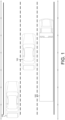
- FIG. 1A is a schematic view of an exemplary overview of a vehicle having a blind spot monitoring system of the present invention in a first exemplary traffic scenario.
-
FIG. 1B is a schematic view of an exemplary overview of a vehicle having a blind spot monitoring system of the present invention in a second exemplary traffic scenario. -
FIG. 1C is a schematic view of an exemplary overview of a vehicle having a blind spot monitoring system of the present invention in a third exemplary traffic scenario. -
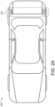
FIG. 2A is a schematic view of an exemplary overview of a vehicle having a blind spot monitoring system of the present invention. -
FIG. 2B is a schematic view of an exemplary blind spot monitoring system for the vehicle shown inFIG. 2A . -
FIG. 3A is schematic view of a first ghost object detection scenario for detecting ghost objects with the blind spot monitoring system shown in Figures 1A-2B . -
FIG. 3B is schematic view of a second ghost object detection scenario for detecting ghost objects with the blind spot monitoring system shown in Figures 1A-2B . -
FIG. 3C is schematic view of a third ghost object detection scenario for detecting ghost objects with the blind spot monitoring system shown in Figures 1A-2B . -
FIG. 3D is schematic view of a fourth ghost object detection scenario for detecting ghost objects with the blind spot monitoring system shown in Figures 1A-2B . -
FIG. 3E is schematic view of a fifth ghost object detection scenario for detecting ghost objects with the blind spot monitoring system shown in Figures 1A-2B . -
FIG. 4 is schematic view of a generalized model for ghost object detection with the blind spot monitoring system shown in Figures 1A-2B . -
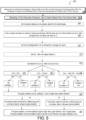
FIG. 5 is an example method for detecting ghost objects with the blind spot monitoring system shown in Figures 1A-2B . -
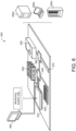
FIG. 6 is a schematic view of an example computing device executing any system or methods described herein. - Like reference symbols in the various drawings indicate like elements.
- Advanced driver safety features have been gaining interest in the past few years. To increase transportation safety of vehicles, it is important to have an accurate idea of identifying objects that are proximate to and/or approaching a vehicle. This is particularly important for areas of the vehicle that are "blind spots" for the vehicle driver. This may include fields of view of the driver that are obstructed by the vehicle itself (traditionally labeled "blind spot") and areas that are obstructed by external objects, such as other vehicles, buildings, etc. that are proximate to the ego vehicle.
- Referring to FIGS. 1A-
5 , avehicle 100 includes a blindspot monitoring system 110 that includes a computing device (or hardware processor) 112 (e.g., central processing unit having one or more computing processors) in communication with non-transitory memory or hardware memory 114 (e.g., a hard disk, flash memory, random-access memory) capable of storing instructions executable on the computing processor(s) 112. The blindspot monitoring system 110 includes asensor system 120. Thesensor system 120 includes one ormore sensors 122a-n positioned at one or more areas and configured to sense one ormore objects Objects vehicles 102a, traffic participants 102b, such as pedestrians and bicyclists, buildings/infrastructure 103b, natural objects, shrubbery, trees, etc. In addition to sensingactual objects sensors sensors objects - In some implementations,
sensors 122 may be short range radar sensors, which provide a broad field of view. The one ormore sensors 122a-n may be positioned to capturedata 124 associated with a specific area 10, where eachsensor 122a-n capturesdata 124 associated with a portion of the area 10. As a result, thesensor data 124 associated with eachsensor 122a-n includessensor data 124 associated with the entire area 10. Thesensors 122 may also include, but are not limited to, Sonar, LIDAR (Light Detection and Ranging, which can entail optical remote sensing that measures properties of scattered light to find range and/or other information of a distant target), HFL (High Flash LIDAR), LADAR (Laser Detection and Ranging). - Each
sensor 122 is positioned at a location where thesensor 122 can capturesensor data 124 associated withobjects sensor system 120 analyses thesensor data 124 captured by the one ormore sensors 122a-n. The analysis of thesensor data 124 includes thesensor system 120 identifying one ormore objects objects - Based on general analysis, there are five types of multipath reflections are observed in a large amount of test data. In
FIGS. 3A-E and4 , R is radar, T is real target, G is ghost object, S is the stationary object which has high reflection index, like parked car, truck or metal guard rail, or reflective wall. Double line arrow means the radar signal passes twice and single line arrow means radar signal passes once. - In
Fig 3A , the radar signal sends out from R, hits a stationary object S, and then reflected out and hit real target T, after that, the signal passes to S and then to R. The name of this figure is RSTSR and it stands for the path of the radar signal. - In
Fig 3B , the radar signal sends out from R, hits a real target T, then hit a stationary object S, after that it goes back to radar with the same path. It is called RTSTR. - In
Fig 3C , the radar signal R bounced twice between the real target T and the stationary object S. It is called RTSTSTR. - In
Fig. 3D , the signal is sent out from radar, reflected by the target T and then by the stationary object S and return to the radar R finally. It is called RTSR. - In
Fig 3E , the signal is sent out from radar R, reflected by the stationary object S, then by the target T and return to radar. It is called RSTR. - In
Fig 3A and 3B , we have:
- In
Fig 3C , we have:
- In
Fig 3D , we have:

- It can be converted to:

- In
Fig 3E , we have:

- We can conclude:

- These five cases are different, and these objects will never satisfy more than one condition. 0.5z cannot equal to z if z is not zero. For equation (3), we have:


- We can get similar conclusion for equation (4). So there will be only one condition be satisfied. Therefore, we can summarize equation (1) to (4):

- In
Fig. 3A-E , there are always three objects, one real object, one ghost object and a stationary object. Two of them and radar sensor are colinear. One of them are not on the line formed by other two objects with radar. - The five reflection cases can be generalized to be one situation as shown in
Fig. 4 . R is the radar sensor, O1 and O2 are two objects, O3 or O3' or O3" is the third object. We can always form a triangle having two edges with the same length. Two objects (O1 and O2) are at two corners of the triangle. Length of edge O1O2 equals that of edge O2O3. The remain object is on the edge O2O3, but the location could be O3, O3' or O3". - In detail, for reflection cases shown in
Fig. 3A , O1 is the real target, O2 is the stationary object and O3 is the ghost object. For the case shown inFig. 3B , O1 is the stationary target, O2 is the real object and O3 is the ghost object. For reflection case shown inFig. 3C , O1 is the stationary object, O2 is the real target. O3" is the ghost object. O3 is the middle point of O2O3" and |O2O3| is 0.5|O2O3"|. For reflection case shown inFig. 3D , O3' will be the ghost object, O1 is the real object and O2 is the stationary object. The length of O2O3 edge of triangle O1O2O3 will be 2rg - rt - x, which can be written as 2RO3' - RO1 - RO2. For reflection case shown inFig. 3E , O1 is the stationary object. O3' is ghost object and O2 is the real target. The length of O2O3 of triangle O1O2O3 will be 2rg - rs - x, which can be also written as 2RO3' - RO1 - RO2. Then formula will be:
- Based on equation (6), a generalized solution as shown in
Fig. 4 is provided to identify ghost object. This solution could be easily implemented to identify ghost object generated from all cases shown inFig. 3A-E . -
FIG. 5 provides an example arrangement of operations for amethod 500 for detecting a ghost object 104, 104a-n using thesystem 110 ofFIGS. 1-4 . Atblock 502, themethod 500 includes receiving, at ahardware processor 112,sensor data 124 from one ormore sensors 122 in communication with thehardware processor 112 and positioned such that the surrounding area 10 is within a field of view of the one ormore sensors 122. Atblock 504, themethod 500 includes detecting, at thehardware processor 112, one ormore objects sensor data 124. Atblock 506, themethod 500 includes identifying, at thehardware processor 112, two dynamic objects and one stationary object from the one ormore objects - Additionally, at
block 508, themethod 500 includes verifying, at thehardware processor 112, that two objects and radar are colinear by checking azimuth angle. Marking the closer one as O2. Marking the further one as Ox. Marking the object that is not colinear with others as O1. - At
block 510, themethod 500 includes determining, at thehardware processor 112, the distance from O1 to O2; RO1 and RO2, the range of O1 and O2. Further, atblock 512, themethod 500 includes determining, at thehardware processor 112, RO3', which is the range of object Ox. Atblock 514, themethod 500 includes determining, at thehardware processor 112, the distance from O2 to Ox and marking as O2O3 and O2O3'. - At
block 516, themethod 500 includes comparing, at thehardware processor 112, whether O1O2 = O2O3. Based on the comparison if O1O2 is equal to O2O3 a Confidence 1(C1) is obtained, at block 518 or C1 is set to 0 if O1O2 is not equal to O2O3, at block 520. - At
block 522, themethod 500 includes comparing, at thehardware processor 112, whether O1O2 = 0.5O2O3'. Based on the comparison if O1O2 is equal to 0.5O2O3' a Confidence 2(C2) is obtained, at block 524 or C2 is set to 0 if O1O2 is not equal 0.5O2O3', at block 526. - At block 528, the
method 500 includes comparing, at thehardware processor 112, whether O1O2 = 2RO3'-RO1 - RO2. Based on the comparison if O1O2 is equal to 2RO3'-RO1 - RO2 a Confidence 3 (C3) is obtained, at block 530 or C3 is set to 0 if O1O2 is not equal to 2RO3'-RO1 - RO2, at block 532. - After C1, C2, and C3 are obtained, the
method 500 includes comparing, at thehardware processor 112, C1, C2, and C3 to determine the highest confidence value among them then comparing the highest confidence to a pre-defined threshold, atblock 534. If the highest confidence value is greater than the predefined threshold, themethod 500 includes finding the dynamic object with less RCS or lifetime among the two dynamic objects and increasing the corresponding ghost probability, at block 536.. If the highest confidence value is not greater than the predefined threshold, themethod 500 includes finding the dynamic object with less RCS or lifetime among the two dynamic objects and decreasing the corresponding ghost probability, at block 538. - Further, at
block 540, themethod 500 includes comparing, at thehardware processor 112, whether the ghost probability of the less confidence object is higher than a upper threshold, and marking it as ghost object or whether the ghost probability of the less confidence object is less than a lower threshold, setting its ghost probability to zero. -
FIG. 6 is schematic view of anexample computing device 600 that may be used to implement the systems and methods described in this document. Thecomputing device 600 is intended to represent various forms of digital computers, such as laptops, desktops, workstations, personal digital assistants, servers, blade servers, mainframes, and other appropriate computers. The components shown here, their connections and relationships, and their functions, are meant to be exemplary only, and are not meant to limit implementations of the inventions described and/or claimed in this document. - The
computing device 600 includes aprocessor 610,memory 620, astorage device 630, a high-speed interface/controller 640 connecting to thememory 620 and high-speed expansion ports 650, and a low speed interface/controller 660 connecting tolow speed bus 670 andstorage device 630. Each of thecomponents processor 610 can process instructions for execution within thecomputing device 600, including instructions stored in thememory 620 or on thestorage device 630 to display graphical information for a graphical user interface (GUI) on an external input/output device, such asdisplay 680 coupled tohigh speed interface 640. In other implementations, multiple processors and/or multiple buses may be used, as appropriate, along with multiple memories and types of memory. Also,multiple computing devices 600 may be connected, with each device providing portions of the necessary operations (e.g., as a server bank, a group of blade servers, or a multi-processor system). - The
memory 620 stores information non-transitorily within thecomputing device 600. Thememory 620 may be a computer-readable medium, a volatile memory unit(s), or non-volatile memory unit(s). Thenon-transitory memory 620 may be physical devices used to store programs (e.g., sequences of instructions) or data (e.g., program state information) on a temporary or permanent basis for use by thecomputing device 600. Examples of non-volatile memory include, but are not limited to, flash memory and read-only memory (ROM) / programmable read-only memory (PROM) / erasable programmable read-only memory (EPROM) / electronically erasable programmable read-only memory (EEPROM) (e.g., typically used for firmware, such as boot programs). Examples of volatile memory include, but are not limited to, random access memory (RAM), dynamic random access memory (DRAM), static random access memory (SRAM), phase change memory (PCM) as well as disks or tapes. - The
storage device 630 is capable of providing mass storage for thecomputing device 600. In some implementations, thestorage device 630 is a computer-readable medium. In various different implementations, thestorage device 630 may be a floppy disk device, a hard disk device, an optical disk device, or a tape device, a flash memory or other similar solid state memory device, or an array of devices, including devices in a storage area network or other configurations. In additional implementations, a computer program product is tangibly embodied in an information carrier. The computer program product contains instructions that, when executed, perform one or more methods, such as those described above. The information carrier is a computer- or machine-readable medium, such as thememory 620, thestorage device 630, or memory onprocessor 610. - The high-
speed controller 640 manages bandwidth-intensive operations for thecomputing device 600, while thelow speed controller 660 manages lower bandwidth-intensive operations. Such allocation of duties is exemplary only. In some implementations, the high-speed controller 640 is coupled to thememory 620, the display 680 (e.g., through a graphics processor or accelerator), and to the high-speed expansion ports 650, which may accept various expansion cards (not shown). In some implementations, the low-speed controller 660 is coupled to thestorage device 630 and low-speed expansion port 670. The low-speed expansion port 670, which may include various communication ports (e.g., USB, Bluetooth, Ethernet, wireless Ethernet), may be coupled to one or more input/output devices, such as a keyboard, a pointing device, a scanner, or a networking device such as a switch or router, e.g., through a network adapter. - The
computing device 600 may be implemented in a number of different forms, as shown in the figure. For example, it may be implemented as astandard server 600a or multiple times in a group ofsuch servers 600a, as alaptop computer 600b, or as part of arack server system 600c. - Various implementations of the systems and techniques described here can be realized in digital electronic and/or optical circuitry, integrated circuitry, specially designed ASICs (application specific integrated circuits), computer hardware, firmware, software, and/or combinations thereof. These various implementations can include implementation in one or more computer programs that are executable and/or interpretable on a programmable system including at least one programmable processor, which may be special or general purpose, coupled to receive data and instructions from, and to transmit data and instructions to, a storage system, at least one input device, and at least one output device.
- These computer programs (also known as programs, software, software applications or code) include machine instructions for a programmable processor, and can be implemented in a high-level procedural and/or object-oriented programming language, and/or in assembly/machine language. As used herein, the terms "machine-readable medium" and "computer-readable medium" refer to any computer program product, non-transitory computer readable medium, apparatus and/or device (e.g., magnetic discs, optical disks, memory, Programmable Logic Devices (PLDs)) used to provide machine instructions and/or data to a programmable processor, including a machine-readable medium that receives machine instructions as a machine-readable signal. The term "machine-readable signal" refers to any signal used to provide machine instructions and/or data to a programmable processor.
- Implementations of the subject matter and the functional operations described in this specification can be implemented in digital electronic circuitry, or in computer software, firmware, or hardware, including the structures disclosed in this specification and their structural equivalents, or in combinations of one or more of them. Moreover, subject matter described in this specification can be implemented as one or more computer program products, i.e., one or more modules of computer program instructions encoded on a computer readable medium for execution by, or to control the operation of, data processing apparatus. The computer readable medium can be a machine-readable storage device, a machine-readable storage substrate, a memory device, a composition of matter effecting a machine-readable propagated signal, or a combination of one or more of them. The terms "data processing apparatus", "computing device" and "computing processor" encompass all apparatus, devices, and machines for processing data, including by way of example a programmable processor, a computer, or multiple processors or computers. The apparatus can include, in addition to hardware, code that creates an execution environment for the computer program in question, e.g., code that constitutes processor firmware, a protocol stack, a database management system, an operating system, or a combination of one or more of them. A propagated signal is an artificially generated signal, e.g., a machine-generated electrical, optical, or electromagnetic signal, that is generated to encode information for transmission to suitable receiver apparatus.
- A computer program (also known as an application, program, software, software application, script, or code) can be written in any form of programming language, including compiled or interpreted languages, and it can be deployed in any form, including as a stand-alone program or as a module, component, subroutine, or other unit suitable for use in a computing environment. A computer program does not necessarily correspond to a file in a file system. A program can be stored in a portion of a file that holds other programs or data (e.g., one or more scripts stored in a markup language document), in a single file dedicated to the program in question, or in multiple coordinated files (e.g., files that store one or more modules, sub programs, or portions of code). A computer program can be deployed to be executed on one computer or on multiple computers that are located at one site or distributed across multiple sites and interconnected by a communication network.
- The processes and logic flows described in this specification can be performed by one or more programmable processors executing one or more computer programs to perform functions by operating on input data and generating output. The processes and logic flows can also be performed by, and apparatus can also be implemented as, special purpose logic circuitry, e.g., an FPGA (field programmable gate array) or an ASIC (application specific integrated circuit).
- Processors suitable for the execution of a computer program include, by way of example, both general and special purpose microprocessors, and any one or more processors of any kind of digital computer. Generally, a processor will receive instructions and data from a read only memory or a random access memory or both. The essential elements of a computer are a processor for performing instructions and one or more memory devices for storing instructions and data. Generally, a computer will also include, or be operatively coupled to receive data from or transfer data to, or both, one or more mass storage devices for storing data, e.g., magnetic, magneto optical disks, or optical disks. However, a computer need not have such devices. Moreover, a computer can be embedded in another device, e.g., a mobile telephone, a personal digital assistant (PDA), a mobile audio player, a Global Positioning System (GPS) receiver, to name just a few. Computer readable media suitable for storing computer program instructions and data include all forms of non-volatile memory, media and memory devices, including by way of example semiconductor memory devices, e.g., EPROM, EEPROM, and flash memory devices; magnetic disks, e.g., internal hard disks or removable disks; magneto optical disks; and CD ROM and DVD-ROM disks. The processor and the memory can be supplemented by, or incorporated in, special purpose logic circuitry.
- To provide for interaction with a user, one or more aspects of the disclosure can be implemented on a computer having a display device, e.g., a CRT (cathode ray tube), LCD (liquid crystal display) monitor, or touch screen for displaying information to the user and optionally a keyboard and a pointing device, e.g., a mouse or a trackball, by which the user can provide input to the computer. Other kinds of devices can be used to provide interaction with a user as well; for example, feedback provided to the user can be any form of sensory feedback, e.g., visual feedback, auditory feedback, or tactile feedback; and input from the user can be received in any form, including acoustic, speech, or tactile input. In addition, a computer can interact with a user by sending documents to and receiving documents from a device that is used by the user; for example, by sending web pages to a web browser on a user's client device in response to requests received from the web browser.
- One or more aspects of the disclosure can be implemented in a computing system that includes a backend component, e.g., as a data server, or that includes a middleware component, e.g., an application server, or that includes a frontend component, e.g., a client computer having a graphical user interface or a Web browser through which a user can interact with an implementation of the subject matter described in this specification, or any combination of one or more such backend, middleware, or frontend components. The components of the system can be interconnected by any form or medium of digital data communication, e.g., a communication network. Examples of communication networks include a local area network ("LAN") and a wide area network ("WAN"), an inter-network (e.g., the Internet), and peer-to-peer networks (e.g., ad hoc peer-to-peer networks).
- The computing system can include clients and servers. A client and server are generally remote from each other and typically interact through a communication network. The relationship of client and server arises by virtue of computer programs running on the respective computers and having a client-server relationship to each other. In some implementations, a server transmits data (e.g., an HTML page) to a client device (e.g., for purposes of displaying data to and receiving user input from a user interacting with the client device). Data generated at the client device (e.g., a result of the user interaction) can be received from the client device at the server.
- While this specification contains many specifics, these should not be construed as limitations on the scope of the disclosure or of what may be claimed, but rather as descriptions of features specific to particular implementations of the disclosure. Certain features that are described in this specification in the context of separate implementations can also be implemented in combination in a single implementation. Conversely, various features that are described in the context of a single implementation can also be implemented in multiple implementations separately or in any suitable subcombination.
- Similarly, while operations are depicted in the drawings in a particular order, this should not be understood as requiring that such operations be performed in the particular order shown or in sequential order, or that all illustrated operations be performed, to achieve desirable results. In certain circumstances, multi-tasking and parallel processing may be advantageous. Moreover, the separation of various system components in the embodiments described above should not be understood as requiring such separation in all embodiments, and it should be understood that the described program components and systems can generally be integrated together in a single software product or packaged into multiple software products.
- The foregoing preferred embodiments have been shown and described for the purposes of illustrating the structural and functional principles of the present invention, as well as illustrating the methods of employing the preferred embodiments and are subject to change without departing from such principles. Therefore, this invention includes all modifications encompassed within the scope of the following claims.
Claims (2)
- A method (500) for classifying an object (104a-n) detected by a radar device (122), the method comprising:receiving (502), at a hardware processor (112), sensor data (124) from at least a first radar sensor (122) in communication with the hardware processor (112) and positioned such that an area (10) surrounding the radar device is within a field of view of the at least a first radar sensor;detecting (504) at least three objects (102, 102a-n) in the area (10) from the sensor data (124);identifying (506), at the hardware processor (112), two dynamic objects and one stationary object from the at least three objects (102, 102a-n);verifying (508), at the hardware processor (112), that two objects of the identified objects and the first radar sensor (122) are colinear by checking azimuth angle;marking the object of the identified objects that is not colinear with others of the identified objects as a first object (O1), marking a closer one of the colinear objects as a second object (O2), marking a further one of the colinear objects as a third object (Ox);determining (510), at the hardware processor (112), a first separation distance from the first object to the second object (0102), a first range from the first radar sensor (122) to the first object (RO1) and a second range from the first radar sensor (122) to the second object (RO2);determining (512), at the hardware processor (112), a second separation distance from the second object to the third object (O2Ox), a third range (RO3') from the first radar sensor to the third object (Ox);comparing (516), at the hardware processor (112), whether the first separation distance (0102) is equal to the second separation distance (O2O3);obtaining (518) a first confidence (C1) when the first separation distance (0102) is equal to the second separation distance (O2O3) and setting the first confidence (C1) to zero when the first separation distance (0102) is not equal to the second separation distance (O2O3);obtaining (524) a second confidence (C2) when the first separation distance (O1O2) is equal to half the second separation distance (O2O3') and setting the second confidence (C1) to zero when the second separation distance (0102) is not equal to half the second separation distance (O2O3');obtaining (530) a third confidence (C3) when the first separation distance (0102) is equal to twice the third range (RO3') minus the first range (RO1) and minus the second range (RO2) and setting the third confidence (C3) to zero when the first separation distance (0102) is not equal to twice the third range (RO3') minus the first range (RO1) and minus the second range (RO2);comparing (534), at the hardware processor (112), the first, second and third confidence (C1, C2, C3) to determine the highest confidence value among them;comparing (534) the highest confidence to a pre-defined threshold;finding the dynamic object with less RCS or lifetime among the two dynamic objects and increasing a corresponding ghost probability when the highest confidence value is higher than the pre-defined threshold, and decreasing the corresponding ghost probability when the highest confidence value is not higher than the pre-defined threshold; andmarking (540) the object as a ghost object when the ghost probability of a less confident object is higher than an upper threshold of ghost probability and setting the ghost probability to zero when the less confident object is lower than a lower threshold of ghost probability.
- A vehicle system configured for performing a safety procedure for a vehicle based on objects in an area surrounding the vehicle, the system comprising:a hardware processor (112); andhardware memory in communication with the hardware processor, the hardware memory storing instructions that when executed on the hardware processor cause the hardware processor to perform operations comprising:receiving (502), at the hardware processor (112), sensor data (124) from at least a first radar sensor (122) in communication with the hardware processor (112) and positioned such that an area (10) surrounding the radar device is within a field of view of the at least first radar sensor;detecting (504) at least three objects (102, 102a-n) in the area (10) from the sensor data (124);identifying (506), at the hardware processor (112), two dynamic objects and one stationary object from the at least three objects (102, 102a-n);verifying (508), at the hardware processor (112), that two objects of the identified objects and the first radar sensor (122) are colinear by checking azimuth angle;marking the object of the identified objects that is not colinear with others of the identified objects as a first object (O1), marking a closer one of the colinear objects as a second object (O2), marking a further one of the colinear objects as a third object (Ox);determining (510), at the hardware processor (112), a first separation distance from the first object to the second object (0102), a first range from the first radar sensor (122) to the first object (RO1) and a second range from the first radar sensor (122) to the second object (RO2);determining (512), at the hardware processor (112), a second separation distance from the second object to the third object (O2Ox), a third range (RO3') from the first radar sensor to the third object (Ox);comparing (516), at the hardware processor (112), whether the first separation distance (0102) is equal to the second separation distance (O2O3);obtaining (518) a first confidence (C1) when the first separation distance (0102) is equal to the second separation distance (O2O3) and setting the first confidence (C1) to zero when the first separation distance (0102) is not equal to the second separation distance (O2O3);obtaining (524) a second confidence (C2) when the first separation distance (O1O2) is equal to half the second separation distance (O2O3') and setting the second confidence (C1) to zero when the second separation distance (0102) is not equal to half the second separation distance (O2O3');obtaining (530) a third confidence (C3) when the first separation distance (0102) is equal to twice the third range (RO3') minus the first range (RO1) and minus the second range (RO2) and setting the third confidence (C3) to zero when the first separation distance (0102) is not equal to twice the third range (RO3') minus the first range (RO1) and minus the second range (RO2);comparing (534), at the hardware processor (112), the first, second and third confidence (C1, C2, C3) to determine the highest confidence value among them;comparing (534) the highest confidence to a pre-defined threshold;
finding the dynamic object with less RCS or lifetime among the two dynamic objects and increasing a corresponding ghost probability when the highest confidence value is higher than the pre-defined threshold, and decreasing the corresponding ghost probability when the highest confidence value is not higher than the pre-defined threshold; andmarking (540) the object as a ghost object when the ghost probability of a less confident object is higher than an upper threshold of ghost probability and setting the ghost probability to zero when the less confident object is lower than a lower threshold of ghost probability.
Applications Claiming Priority (2)
| Application Number | Priority Date | Filing Date | Title |
|---|---|---|---|
| US201962830971P | 2019-04-08 | 2019-04-08 | |
| PCT/US2020/027202 WO2020210307A1 (en) | 2019-04-08 | 2020-04-08 | Ghost object identification for automobile radar tracking |
Publications (2)
| Publication Number | Publication Date |
|---|---|
| EP3921670A1 EP3921670A1 (en) | 2021-12-15 |
| EP3921670B1 true EP3921670B1 (en) | 2024-11-20 |
Family
ID=70482824
Family Applications (1)
| Application Number | Title | Priority Date | Filing Date |
|---|---|---|---|
| EP20723648.0A Active EP3921670B1 (en) | 2019-04-08 | 2020-04-08 | Ghost object identification for automobile radar tracking |
Country Status (5)
| Country | Link |
|---|---|
| US (1) | US12196841B2 (en) |
| EP (1) | EP3921670B1 (en) |
| JP (1) | JP7582965B2 (en) |
| CN (1) | CN113678022B (en) |
| WO (1) | WO2020210307A1 (en) |
Families Citing this family (12)
| Publication number | Priority date | Publication date | Assignee | Title |
|---|---|---|---|---|
| KR102332509B1 (en) * | 2020-05-22 | 2021-11-29 | 현대모비스 주식회사 | Method and apparatus for rear cross collision warning |
| DE102020121108A1 (en) * | 2020-08-11 | 2022-02-17 | Bayerische Motoren Werke Aktiengesellschaft | Method for detecting road users in the vicinity of a vehicle based on measurements from a radar sensor by identifying interference detections, and computing device |
| US11774583B2 (en) | 2021-02-26 | 2023-10-03 | Waymo Llc | Methods and systems for filtering vehicle self-reflections in radar |
| CN112986945B (en) * | 2021-03-05 | 2022-08-02 | 森思泰克河北科技有限公司 | Radar target identification method, device, equipment and storage medium |
| US12000957B2 (en) * | 2021-06-24 | 2024-06-04 | Intel Corporation | Range doppler consistency check for radar ghost target detection |
| DE102021211989B3 (en) * | 2021-10-25 | 2022-11-10 | Continental Autonomous Mobility Germany GmbH | Method and system for associating real targets and their mirror targets |
| DE102022211987A1 (en) | 2021-11-12 | 2023-05-17 | Zf Friedrichshafen Ag | Method, computer program, machine-readable storage medium and system for classifying ghost objects in an environment of a road vehicle, a transportation system and/or a component of a traffic infrastructure |
| DE102022000331A1 (en) * | 2022-01-28 | 2022-03-17 | Daimler Ag | Method for detecting ghost objects in sensor measurements |
| WO2023199457A1 (en) * | 2022-04-14 | 2023-10-19 | 三菱電機株式会社 | Target position estimation device, radar device, and target position estimation method |
| CN115079121B (en) * | 2022-07-19 | 2022-11-01 | 南京隼眼电子科技有限公司 | Multipath target identification method and device for vehicle-mounted radar and storage medium |
| KR102870530B1 (en) * | 2022-08-18 | 2025-10-14 | 메타빌드 주식회사 | System and method for detecting separation ghost object generated by multipath signal of radar sensor |
| KR20240062227A (en) | 2022-10-28 | 2024-05-09 | 삼성전기주식회사 | Target detection method and apparatus |
Family Cites Families (32)
| Publication number | Priority date | Publication date | Assignee | Title |
|---|---|---|---|---|
| GB1231794A (en) | 1967-05-03 | 1971-05-12 | ||
| US4970518A (en) * | 1988-12-07 | 1990-11-13 | Westinghouse Electric Corp. | Air traffic control radar beacon system multipath reduction apparatus and method |
| US5877721A (en) | 1998-02-20 | 1999-03-02 | Northrop Grumman Corporation | Apparatus and method for mitigating multipath |
| DE10252323A1 (en) * | 2002-11-11 | 2004-05-19 | Ibeo Automobile Sensor Gmbh | Method for determining an own movement of a vehicle |
| JP2005257515A (en) | 2004-03-12 | 2005-09-22 | Mitsubishi Electric Corp | Radar equipment |
| DE102004058844A1 (en) | 2004-12-06 | 2006-06-08 | Daimlerchrysler Ag | Traffic condition detecting method, involves detecting virtual reflection points by looped around radar radiations, where reflection points are included in computation for detection of traffic condition |
| JP4529733B2 (en) | 2005-03-02 | 2010-08-25 | 株式会社デンソー | In-vehicle radar system |
| JP4850898B2 (en) | 2006-02-16 | 2012-01-11 | 三菱電機株式会社 | Radar equipment |
| US8330642B2 (en) * | 2007-07-09 | 2012-12-11 | Carnegie Mellon University | Imaging by time reversal beamforming |
| JP2009074804A (en) | 2007-09-18 | 2009-04-09 | Toyota Motor Corp | Object detection device |
| DE102012208852A1 (en) | 2012-05-25 | 2013-11-28 | Robert Bosch Gmbh | Detection of radar objects with a radar sensor of a motor vehicle |
| DE102012108023B4 (en) | 2012-08-30 | 2021-03-25 | Conti Temic Microelectronic Gmbh | Radar-based detection of roadside development through the use of multipath propagation |
| KR101927155B1 (en) * | 2012-10-19 | 2018-12-10 | 현대자동차 주식회사 | Method and system for recognizing space of shoulder of road |
| US9995822B2 (en) | 2013-06-13 | 2018-06-12 | Continental Automotive Systems, Inc. | Integration of a radar sensor in a vehicle |
| GB2517710A (en) | 2013-08-28 | 2015-03-04 | Aveillant Ltd | Radar system and associated apparatus and methods |
| JP6217349B2 (en) | 2013-11-28 | 2017-10-25 | トヨタ自動車株式会社 | Braking device |
| WO2016003473A1 (en) * | 2014-07-03 | 2016-01-07 | GM Global Technology Operations LLC | Vehicle radar methods and systems |
| US9759811B2 (en) * | 2014-12-08 | 2017-09-12 | Honeywell International Inc. | Radar vehicle tracking |
| US20160209211A1 (en) * | 2015-01-16 | 2016-07-21 | GM Global Technology Operations LLC | Method for determining misalignment of an object sensor |
| JP2016148547A (en) | 2015-02-10 | 2016-08-18 | トヨタ自動車株式会社 | Detection device |
| US10259453B2 (en) | 2015-04-10 | 2019-04-16 | Continental Automotive Systems, Inc. | Collision avoidance based on front wheel off tracking during reverse operation |
| KR102488038B1 (en) | 2015-11-19 | 2023-01-13 | 주식회사 에이치엘클레무브 | Radar apparatus for vehicle and method for determining target of the same |
| JP2017096840A (en) | 2015-11-26 | 2017-06-01 | トヨタ自動車株式会社 | Vehicular target detection apparatus |
| EP3211444B1 (en) | 2016-02-29 | 2019-06-12 | Nxp B.V. | Radar system |
| KR20170140005A (en) | 2016-06-10 | 2017-12-20 | 주식회사 앱스 | An Object Identification Device using Laser Scanner with Ghost Object Identification Function |
| DE102016215505A1 (en) | 2016-08-18 | 2018-02-22 | Continental Automotive Gmbh | Ghost target detection in a radar system in a vehicle. |
| EP3299841B1 (en) * | 2016-09-22 | 2022-05-04 | Continental Automotive GmbH | Method and apparatus for analyzing reflection signals, driver assistance system, and vehicle |
| WO2018142629A1 (en) | 2017-02-06 | 2018-08-09 | 日本電気株式会社 | Object detection device, object detection method, and computer readable recording medium |
| EP3385745B1 (en) | 2017-04-06 | 2021-03-03 | Volvo Car Corporation | Method and system for determining the position of a user device in relation to a vehicle |
| JP7053982B2 (en) * | 2017-05-25 | 2022-04-13 | ミツミ電機株式会社 | Ghost removal method and radar device |
| KR102026697B1 (en) * | 2017-09-21 | 2019-09-30 | 엘지전자 주식회사 | Driving system and vehicle |
| CN109559525B (en) | 2018-11-26 | 2020-08-04 | 厦门精益远达智能科技有限公司 | Overspeed monitoring method, device and equipment based on millimeter wave radar |
-
2020
- 2020-04-08 JP JP2021559662A patent/JP7582965B2/en active Active
- 2020-04-08 CN CN202080027137.XA patent/CN113678022B/en active Active
- 2020-04-08 US US17/594,278 patent/US12196841B2/en active Active
- 2020-04-08 WO PCT/US2020/027202 patent/WO2020210307A1/en not_active Ceased
- 2020-04-08 EP EP20723648.0A patent/EP3921670B1/en active Active
Also Published As
| Publication number | Publication date |
|---|---|
| WO2020210307A1 (en) | 2020-10-15 |
| JP2022526819A (en) | 2022-05-26 |
| US20220163649A1 (en) | 2022-05-26 |
| CN113678022A (en) | 2021-11-19 |
| EP3921670A1 (en) | 2021-12-15 |
| US12196841B2 (en) | 2025-01-14 |
| JP7582965B2 (en) | 2024-11-13 |
| CN113678022B (en) | 2024-09-20 |
Similar Documents
| Publication | Publication Date | Title |
|---|---|---|
| US12196841B2 (en) | Ghost object identification for automobile radar tracking | |
| US6687577B2 (en) | Simple classification scheme for vehicle/pole/pedestrian detection | |
| US8818702B2 (en) | System and method for tracking objects | |
| US8558679B2 (en) | Method of analyzing the surroundings of a vehicle | |
| JP6450294B2 (en) | Object detection apparatus, object detection method, and program | |
| KR102699140B1 (en) | Apparatus and method for predicting concurrent lane change vehicle and vehicle including the same | |
| CN109188438A (en) | Yaw angle determines method, apparatus, equipment and medium | |
| US11358600B2 (en) | Control system and control method for a motor vehicle for processing multiply reflected signals | |
| CN112639811B (en) | Method for evaluating sensor data with extended object recognition | |
| CN108028017A (en) | Method for distinguishing real obstruction and false barrier in the driver assistance system of motor vehicle | |
| JP2010132056A (en) | Sensing device, sensing method, and vehicle control device | |
| US20230090259A1 (en) | Sensor information fusion method and device, and recording medium recording program for executing the method | |
| EP3299841A1 (en) | Method and apparatus for analyzing reflection signals, driver assistance system, and vehicle | |
| US20150175204A1 (en) | Apparatus and method for recognizing driving field of vehicle | |
| US20190212153A1 (en) | Vehicle position estimate using information from infrastructure | |
| Tao et al. | Traffic incident detection based on mmWave radar and improvement using fusion with camera | |
| US11307292B2 (en) | ODM information reliability determination system and method and vehicle using the same | |
| CN110095776B (en) | Method for determining the presence and/or the characteristics of an object and surrounding identification device | |
| US10997858B2 (en) | System and method for determining parking occupancy detection using a heat map | |
| KR102337034B1 (en) | Autonomous driving situation recognition program performance test method and apparatus for porceeding the same | |
| JP5321640B2 (en) | Vehicular road shape recognition method and apparatus, and recording medium | |
| US11288957B2 (en) | System and method for detecting one way driving using a heat map | |
| WO2025213724A1 (en) | Relative vehicle distance calculation method and apparatus, and device and readable storage medium | |
| CN116136596A (en) | Vehicle radar system and method for detecting moving object by vehicle radar system | |
| WO2021081371A1 (en) | Method and system to protect a rider from threatening objects approaching a motorbike or bicycle |
Legal Events
| Date | Code | Title | Description |
|---|---|---|---|
| STAA | Information on the status of an ep patent application or granted ep patent |
Free format text: STATUS: UNKNOWN |
|
| STAA | Information on the status of an ep patent application or granted ep patent |
Free format text: STATUS: THE INTERNATIONAL PUBLICATION HAS BEEN MADE |
|
| PUAI | Public reference made under article 153(3) epc to a published international application that has entered the european phase |
Free format text: ORIGINAL CODE: 0009012 |
|
| STAA | Information on the status of an ep patent application or granted ep patent |
Free format text: STATUS: REQUEST FOR EXAMINATION WAS MADE |
|
| 17P | Request for examination filed |
Effective date: 20210907 |
|
| AK | Designated contracting states |
Kind code of ref document: A1 Designated state(s): AL AT BE BG CH CY CZ DE DK EE ES FI FR GB GR HR HU IE IS IT LI LT LU LV MC MK MT NL NO PL PT RO RS SE SI SK SM TR |
|
| DAV | Request for validation of the european patent (deleted) | ||
| DAX | Request for extension of the european patent (deleted) | ||
| RAP1 | Party data changed (applicant data changed or rights of an application transferred) |
Owner name: CONTINENTAL AUTONOMOUS MOBILITY US, LLC |
|
| GRAP | Despatch of communication of intention to grant a patent |
Free format text: ORIGINAL CODE: EPIDOSNIGR1 |
|
| STAA | Information on the status of an ep patent application or granted ep patent |
Free format text: STATUS: GRANT OF PATENT IS INTENDED |
|
| INTG | Intention to grant announced |
Effective date: 20240708 |
|
| GRAS | Grant fee paid |
Free format text: ORIGINAL CODE: EPIDOSNIGR3 |
|
| GRAA | (expected) grant |
Free format text: ORIGINAL CODE: 0009210 |
|
| STAA | Information on the status of an ep patent application or granted ep patent |
Free format text: STATUS: THE PATENT HAS BEEN GRANTED |
|
| AK | Designated contracting states |
Kind code of ref document: B1 Designated state(s): AL AT BE BG CH CY CZ DE DK EE ES FI FR GB GR HR HU IE IS IT LI LT LU LV MC MK MT NL NO PL PT RO RS SE SI SK SM TR |
|
| REG | Reference to a national code |
Ref country code: GB Ref legal event code: FG4D |
|
| REG | Reference to a national code |
Ref country code: CH Ref legal event code: EP |
|
| REG | Reference to a national code |
Ref country code: DE Ref legal event code: R096 Ref document number: 602020041639 Country of ref document: DE |
|
| REG | Reference to a national code |
Ref country code: IE Ref legal event code: FG4D |
|
| REG | Reference to a national code |
Ref country code: LT Ref legal event code: MG9D |
|
| REG | Reference to a national code |
Ref country code: NL Ref legal event code: MP Effective date: 20241120 |
|
| PG25 | Lapsed in a contracting state [announced via postgrant information from national office to epo] |
Ref country code: PT Free format text: LAPSE BECAUSE OF FAILURE TO SUBMIT A TRANSLATION OF THE DESCRIPTION OR TO PAY THE FEE WITHIN THE PRESCRIBED TIME-LIMIT Effective date: 20250320 Ref country code: IS Free format text: LAPSE BECAUSE OF FAILURE TO SUBMIT A TRANSLATION OF THE DESCRIPTION OR TO PAY THE FEE WITHIN THE PRESCRIBED TIME-LIMIT Effective date: 20250320 Ref country code: HR Free format text: LAPSE BECAUSE OF FAILURE TO SUBMIT A TRANSLATION OF THE DESCRIPTION OR TO PAY THE FEE WITHIN THE PRESCRIBED TIME-LIMIT Effective date: 20241120 |
|
| PG25 | Lapsed in a contracting state [announced via postgrant information from national office to epo] |
Ref country code: FI Free format text: LAPSE BECAUSE OF FAILURE TO SUBMIT A TRANSLATION OF THE DESCRIPTION OR TO PAY THE FEE WITHIN THE PRESCRIBED TIME-LIMIT Effective date: 20241120 Ref country code: NL Free format text: LAPSE BECAUSE OF FAILURE TO SUBMIT A TRANSLATION OF THE DESCRIPTION OR TO PAY THE FEE WITHIN THE PRESCRIBED TIME-LIMIT Effective date: 20241120 |
|
| REG | Reference to a national code |
Ref country code: AT Ref legal event code: MK05 Ref document number: 1744059 Country of ref document: AT Kind code of ref document: T Effective date: 20241120 |
|
| PG25 | Lapsed in a contracting state [announced via postgrant information from national office to epo] |
Ref country code: BG Free format text: LAPSE BECAUSE OF FAILURE TO SUBMIT A TRANSLATION OF THE DESCRIPTION OR TO PAY THE FEE WITHIN THE PRESCRIBED TIME-LIMIT Effective date: 20241120 |
|
| PG25 | Lapsed in a contracting state [announced via postgrant information from national office to epo] |
Ref country code: ES Free format text: LAPSE BECAUSE OF FAILURE TO SUBMIT A TRANSLATION OF THE DESCRIPTION OR TO PAY THE FEE WITHIN THE PRESCRIBED TIME-LIMIT Effective date: 20241120 |
|
| PG25 | Lapsed in a contracting state [announced via postgrant information from national office to epo] |
Ref country code: NO Free format text: LAPSE BECAUSE OF FAILURE TO SUBMIT A TRANSLATION OF THE DESCRIPTION OR TO PAY THE FEE WITHIN THE PRESCRIBED TIME-LIMIT Effective date: 20250220 |
|
| PG25 | Lapsed in a contracting state [announced via postgrant information from national office to epo] |
Ref country code: LV Free format text: LAPSE BECAUSE OF FAILURE TO SUBMIT A TRANSLATION OF THE DESCRIPTION OR TO PAY THE FEE WITHIN THE PRESCRIBED TIME-LIMIT Effective date: 20241120 Ref country code: AT Free format text: LAPSE BECAUSE OF FAILURE TO SUBMIT A TRANSLATION OF THE DESCRIPTION OR TO PAY THE FEE WITHIN THE PRESCRIBED TIME-LIMIT Effective date: 20241120 Ref country code: GR Free format text: LAPSE BECAUSE OF FAILURE TO SUBMIT A TRANSLATION OF THE DESCRIPTION OR TO PAY THE FEE WITHIN THE PRESCRIBED TIME-LIMIT Effective date: 20250221 |
|
| PG25 | Lapsed in a contracting state [announced via postgrant information from national office to epo] |
Ref country code: PL Free format text: LAPSE BECAUSE OF FAILURE TO SUBMIT A TRANSLATION OF THE DESCRIPTION OR TO PAY THE FEE WITHIN THE PRESCRIBED TIME-LIMIT Effective date: 20241120 |
|
| PG25 | Lapsed in a contracting state [announced via postgrant information from national office to epo] |
Ref country code: RS Free format text: LAPSE BECAUSE OF FAILURE TO SUBMIT A TRANSLATION OF THE DESCRIPTION OR TO PAY THE FEE WITHIN THE PRESCRIBED TIME-LIMIT Effective date: 20250220 |
|
| PG25 | Lapsed in a contracting state [announced via postgrant information from national office to epo] |
Ref country code: SM Free format text: LAPSE BECAUSE OF FAILURE TO SUBMIT A TRANSLATION OF THE DESCRIPTION OR TO PAY THE FEE WITHIN THE PRESCRIBED TIME-LIMIT Effective date: 20241120 |
|
| PGFP | Annual fee paid to national office [announced via postgrant information from national office to epo] |
Ref country code: DE Payment date: 20250430 Year of fee payment: 6 |
|
| PG25 | Lapsed in a contracting state [announced via postgrant information from national office to epo] |
Ref country code: DK Free format text: LAPSE BECAUSE OF FAILURE TO SUBMIT A TRANSLATION OF THE DESCRIPTION OR TO PAY THE FEE WITHIN THE PRESCRIBED TIME-LIMIT Effective date: 20241120 |
|
| PGFP | Annual fee paid to national office [announced via postgrant information from national office to epo] |
Ref country code: IT Payment date: 20250424 Year of fee payment: 6 |
|
| PG25 | Lapsed in a contracting state [announced via postgrant information from national office to epo] |
Ref country code: EE Free format text: LAPSE BECAUSE OF FAILURE TO SUBMIT A TRANSLATION OF THE DESCRIPTION OR TO PAY THE FEE WITHIN THE PRESCRIBED TIME-LIMIT Effective date: 20241120 |
|
| PGFP | Annual fee paid to national office [announced via postgrant information from national office to epo] |
Ref country code: FR Payment date: 20250425 Year of fee payment: 6 |
|
| PG25 | Lapsed in a contracting state [announced via postgrant information from national office to epo] |
Ref country code: RO Free format text: LAPSE BECAUSE OF FAILURE TO SUBMIT A TRANSLATION OF THE DESCRIPTION OR TO PAY THE FEE WITHIN THE PRESCRIBED TIME-LIMIT Effective date: 20241120 |
|
| PG25 | Lapsed in a contracting state [announced via postgrant information from national office to epo] |
Ref country code: SK Free format text: LAPSE BECAUSE OF FAILURE TO SUBMIT A TRANSLATION OF THE DESCRIPTION OR TO PAY THE FEE WITHIN THE PRESCRIBED TIME-LIMIT Effective date: 20241120 |
|
| PG25 | Lapsed in a contracting state [announced via postgrant information from national office to epo] |
Ref country code: CZ Free format text: LAPSE BECAUSE OF FAILURE TO SUBMIT A TRANSLATION OF THE DESCRIPTION OR TO PAY THE FEE WITHIN THE PRESCRIBED TIME-LIMIT Effective date: 20241120 |
|
| REG | Reference to a national code |
Ref country code: DE Ref legal event code: R097 Ref document number: 602020041639 Country of ref document: DE |
|
| PG25 | Lapsed in a contracting state [announced via postgrant information from national office to epo] |
Ref country code: SE Free format text: LAPSE BECAUSE OF FAILURE TO SUBMIT A TRANSLATION OF THE DESCRIPTION OR TO PAY THE FEE WITHIN THE PRESCRIBED TIME-LIMIT Effective date: 20241120 |
|
| PLBE | No opposition filed within time limit |
Free format text: ORIGINAL CODE: 0009261 |
|
| STAA | Information on the status of an ep patent application or granted ep patent |
Free format text: STATUS: NO OPPOSITION FILED WITHIN TIME LIMIT |
|
| 26N | No opposition filed |
Effective date: 20250821 |
|
| REG | Reference to a national code |
Ref country code: CH Ref legal event code: H13 Free format text: ST27 STATUS EVENT CODE: U-0-0-H10-H13 (AS PROVIDED BY THE NATIONAL OFFICE) Effective date: 20251125 |
|
| PG25 | Lapsed in a contracting state [announced via postgrant information from national office to epo] |
Ref country code: LU Free format text: LAPSE BECAUSE OF NON-PAYMENT OF DUE FEES Effective date: 20250408 |
|
| PG25 | Lapsed in a contracting state [announced via postgrant information from national office to epo] |
Ref country code: MC Free format text: LAPSE BECAUSE OF FAILURE TO SUBMIT A TRANSLATION OF THE DESCRIPTION OR TO PAY THE FEE WITHIN THE PRESCRIBED TIME-LIMIT Effective date: 20241120 |
|
| GBPC | Gb: european patent ceased through non-payment of renewal fee |
Effective date: 20250408 |
|
| REG | Reference to a national code |
Ref country code: BE Ref legal event code: MM Effective date: 20250430 |
|
| PG25 | Lapsed in a contracting state [announced via postgrant information from national office to epo] |
Ref country code: GB Free format text: LAPSE BECAUSE OF NON-PAYMENT OF DUE FEES Effective date: 20250408 |
|
| PG25 | Lapsed in a contracting state [announced via postgrant information from national office to epo] |
Ref country code: BE Free format text: LAPSE BECAUSE OF NON-PAYMENT OF DUE FEES Effective date: 20250430 |
|
| PG25 | Lapsed in a contracting state [announced via postgrant information from national office to epo] |
Ref country code: CH Free format text: LAPSE BECAUSE OF NON-PAYMENT OF DUE FEES Effective date: 20250430 |
|
| REG | Reference to a national code |
Ref country code: DE Ref legal event code: R084 Ref document number: 602020041639 Country of ref document: DE |
|
| PG25 | Lapsed in a contracting state [announced via postgrant information from national office to epo] |
Ref country code: IE Free format text: LAPSE BECAUSE OF NON-PAYMENT OF DUE FEES Effective date: 20250408 |