EP3921215B1 - Electronically controlled pneumatic railway car with end of train device mode - Google Patents
Electronically controlled pneumatic railway car with end of train device mode Download PDFInfo
- Publication number
- EP3921215B1 EP3921215B1 EP19707530.2A EP19707530A EP3921215B1 EP 3921215 B1 EP3921215 B1 EP 3921215B1 EP 19707530 A EP19707530 A EP 19707530A EP 3921215 B1 EP3921215 B1 EP 3921215B1
- Authority
- EP
- European Patent Office
- Prior art keywords
- train
- electronically controlled
- railway car
- controlled pneumatic
- car
- Prior art date
- Legal status (The legal status is an assumption and is not a legal conclusion. Google has not performed a legal analysis and makes no representation as to the accuracy of the status listed.)
- Active
Links
Images


Classifications
-
- B—PERFORMING OPERATIONS; TRANSPORTING
- B61—RAILWAYS
- B61L—GUIDING RAILWAY TRAFFIC; ENSURING THE SAFETY OF RAILWAY TRAFFIC
- B61L15/00—Indicators provided on the vehicle or train for signalling purposes
- B61L15/0054—Train integrity supervision, e.g. end-of-train [EOT] devices
-
- B—PERFORMING OPERATIONS; TRANSPORTING
- B60—VEHICLES IN GENERAL
- B60T—VEHICLE BRAKE CONTROL SYSTEMS OR PARTS THEREOF; BRAKE CONTROL SYSTEMS OR PARTS THEREOF, IN GENERAL; ARRANGEMENT OF BRAKING ELEMENTS ON VEHICLES IN GENERAL; PORTABLE DEVICES FOR PREVENTING UNWANTED MOVEMENT OF VEHICLES; VEHICLE MODIFICATIONS TO FACILITATE COOLING OF BRAKES
- B60T13/00—Transmitting braking action from initiating means to ultimate brake actuator with power assistance or drive; Brake systems incorporating such transmitting means, e.g. air-pressure brake systems
- B60T13/10—Transmitting braking action from initiating means to ultimate brake actuator with power assistance or drive; Brake systems incorporating such transmitting means, e.g. air-pressure brake systems with fluid assistance, drive, or release
- B60T13/66—Electrical control in fluid-pressure brake systems
- B60T13/665—Electrical control in fluid-pressure brake systems the systems being specially adapted for transferring two or more command signals, e.g. railway systems
-
- B—PERFORMING OPERATIONS; TRANSPORTING
- B60—VEHICLES IN GENERAL
- B60T—VEHICLE BRAKE CONTROL SYSTEMS OR PARTS THEREOF; BRAKE CONTROL SYSTEMS OR PARTS THEREOF, IN GENERAL; ARRANGEMENT OF BRAKING ELEMENTS ON VEHICLES IN GENERAL; PORTABLE DEVICES FOR PREVENTING UNWANTED MOVEMENT OF VEHICLES; VEHICLE MODIFICATIONS TO FACILITATE COOLING OF BRAKES
- B60T13/00—Transmitting braking action from initiating means to ultimate brake actuator with power assistance or drive; Brake systems incorporating such transmitting means, e.g. air-pressure brake systems
- B60T13/10—Transmitting braking action from initiating means to ultimate brake actuator with power assistance or drive; Brake systems incorporating such transmitting means, e.g. air-pressure brake systems with fluid assistance, drive, or release
- B60T13/66—Electrical control in fluid-pressure brake systems
- B60T13/68—Electrical control in fluid-pressure brake systems by electrically-controlled valves
- B60T13/683—Electrical control in fluid-pressure brake systems by electrically-controlled valves in pneumatic systems or parts thereof
-
- B—PERFORMING OPERATIONS; TRANSPORTING
- B60—VEHICLES IN GENERAL
- B60T—VEHICLE BRAKE CONTROL SYSTEMS OR PARTS THEREOF; BRAKE CONTROL SYSTEMS OR PARTS THEREOF, IN GENERAL; ARRANGEMENT OF BRAKING ELEMENTS ON VEHICLES IN GENERAL; PORTABLE DEVICES FOR PREVENTING UNWANTED MOVEMENT OF VEHICLES; VEHICLE MODIFICATIONS TO FACILITATE COOLING OF BRAKES
- B60T17/00—Component parts, details, or accessories of power brake systems not covered by groups B60T8/00, B60T13/00 or B60T15/00, or presenting other characteristic features
- B60T17/18—Safety devices; Monitoring
- B60T17/22—Devices for monitoring or checking brake systems; Signal devices
- B60T17/228—Devices for monitoring or checking brake systems; Signal devices for railway vehicles
-
- B—PERFORMING OPERATIONS; TRANSPORTING
- B61—RAILWAYS
- B61L—GUIDING RAILWAY TRAFFIC; ENSURING THE SAFETY OF RAILWAY TRAFFIC
- B61L15/00—Indicators provided on the vehicle or train for signalling purposes
- B61L15/0018—Communication with or on the vehicle or train
- B61L15/0036—Conductor-based, e.g. using CAN-Bus, train-line or optical fibres
-
- B—PERFORMING OPERATIONS; TRANSPORTING
- B61—RAILWAYS
- B61L—GUIDING RAILWAY TRAFFIC; ENSURING THE SAFETY OF RAILWAY TRAFFIC
- B61L25/00—Recording or indicating positions or identities of vehicles or trains or setting of track apparatus
- B61L25/02—Indicating or recording positions or identities of vehicles or trains
- B61L25/023—Determination of driving direction of vehicle or train
-
- B—PERFORMING OPERATIONS; TRANSPORTING
- B61—RAILWAYS
- B61L—GUIDING RAILWAY TRAFFIC; ENSURING THE SAFETY OF RAILWAY TRAFFIC
- B61L25/00—Recording or indicating positions or identities of vehicles or trains or setting of track apparatus
- B61L25/02—Indicating or recording positions or identities of vehicles or trains
- B61L25/028—Determination of vehicle position and orientation within a train consist, e.g. serialisation
Definitions
- the present invention relates to end-of-train functions and, more specifically, to a system and method of providing end-of-train functions in an electronically controlled pneumatic railway car.
- a traditional an end-of-train (EOT) device is an electronic device mounted on the last railway car of a train that can monitor and provide information, such as brake system status, to a head-end-unit (HEU) at the front of the train.
- Conventional EOT devices are powered by batteries that must be sufficiently charged at train departure and during a route.
- both the EOT devices and the batteries are subject to incorrect installation and equipment failure, thereby increasing maintenance costs, disrupting the operation of the train, and causing schedule delays.
- CA 2 290 728 A1 discloses a multifunctional end-of-train device using an arming switch for indicating that a railway car is positioned at the end of train, without however identifying the orientation of the concerned railway car.
- US 5 777 547 A discloses another similar train car identification system.
- the present invention suggests the end-of-train system defined in Claim 1 and the method of providing end-of-train functions defined in Claim 8. Further advantageous features are set out in the dependent claims.
- EOT end-of-train
- ECP electronically controlled pneumatic
- FIG. 1 an end-of-train (EOT) system 10 that is implemented in connection with an electronically controlled pneumatic (ECP) railway car 12 that can be configured to act in an EOT device mode.
- ECP car 12 is associated with a selection device 14 that can be used to manually select EOT device mode for ECP car 12. More specifically, the selection of EOT functions using selection device 14 is detected by an input/output (I/O) end-of-train module 16 that is in communication with the car control device (CCD) 18 of ECP car 12 and railcar specific identification module (IDM) 20.
- I/O input/output
- CCD car control device
- IDDM railcar specific identification module
- I/O module is programmed to implement EOT device mode according to the present invention by establishing the transmission of EOT status messages (referred to as EOT beacons) from ECP car 12 to the Head End Unit (HEU) of the train as well as the isolation of whichever of "A" end intercar ECP trainline communication network (ECP T/L) connector 22 or "B" end intercar ECP trainline connector 24 is positioned at the end of the train.
- EOT beacons EOT status messages
- I/O module When I/O module detects initiation of EOT functions via selection device 14, I/O module places ECP car 12 into an EOT device mode whereby ECP car 12 acts as an EOT device.
- ECP car 12 provides the appropriate EOT status information to the HEU via connector 22 or 24 to indicate that ECP car 12 is at the end of the train.
- CCD 18 obtains ECP car 12 identification using IDM 20 that provides a car specific network node, connects to the ECP network via the appropriate intercar connector 22 or 24, and identifies itself to the Head End Unit (HEU) as being in EOT device mode.
- CCD 18 also begins transmission of EOT status messages and ECP car identification to the HEU.
- ECP car 12 will communicate with the HEU regardless of its "A" or "B" orientation in the train to ensure inclusion of ECP car 12 in the train makeup as the last car in the train and to ensure that ECP car 12 is properly identified and is recognized as the ECP car 12 providing EOT device functionality.
- EOT beacons and identifying information are received by HEU from ECP car 12
- ECP trainline power can be energized so that the conventional ECP RUN Mode may be selected by the train operator. For safety, the trainline may not be energized until an EOT signal is received, thereby demonstrating that the makeup of the train is complete.
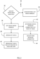
- an exemplary process 30 implemented by I/O module 16 begins with a check whether EOT mode has been selected 32. If not, the conventional ECP mode is enabled 34 for ECP car 12. If so, EOT device mode is enabled 36. The ECP car ID is then obtained 38, and the ECP car ID and EOT beacons are broadcast 40 to the head end unit. As the same time, a determination is made which intercar connector is at the rear of the train 42 and that intercar connector is electrically isolated 44. The determination is made based on selection device 14, where one position must be selected before CCD 18 will enter EOT mode and begin broadcasting. Thus, steps 42 and 44 may be performed using selection device 14 rather than software.
- CCD 18 will continue to transmit EOT beacons, normally once per second, to HEU, thereby acting as the last physical network node on the train.
- ECP car 12 can provide traditional EOT device train break-in-two detection by delivering continuous brake pipe pressure status to HEU.
- CCD 18 may thus include a brake pipe (BP) pressure transducer for determining EOT BP pressure status. This pressure status reporting can be used to verify trainline brake pipe continuity and to provide closed cut-out cock detection.
- ECP car 12 when switched into EOT device mode, can additionally transmit conventional ECP Car brake status information to HEU as it would normally do when acting as a conventional ECP car.
- CCD 18 will transmit normal ECP car brake fault messages to HEU, just as any other ECP car in the train would do.
- EOT beacon transmissions to HEU will cease, thereby resulting in stoppage of the train as would be the case in the event of a failure of a conventional EOT device.
- ECP car 12 is additionally configured to de-energize the rear-most intercar connector of ECP car 12 to mitigate any potential electrical shock hazard.
- ECP car 12 is configured to electrically isolate the rearmost "A" or "B" intercar connector 22 or 24.
- selection device 14 may comprise a switch having three positions, i.e., normal ECP, EOT mode with "A" intercar connector 22 at the rear, or EOT mode with "B" intercar connector 24 at the rear. ECP trainline voltage is then isolated to whichever intercar connector 22 or 24 is indicated by device 14 to be rearmost and thus to be isolated.
- the end of traine intercar connector isolation circuit include a 50 ohm resistor/capacitor to provide network termination.
- the last connector is isolated from trainline power so there is no 240V direct current (DC) on the end of the train connector.
- Selection device 14 may be a manually operated or controlled remotely via electronic signaling.
- Selection device 14 may alternatively comprise a separate smart module coupled to the rearmost intercar connector 22 or 24 that physically isolates that intercar connector 22 or 24 and communicates back to I/O to signal to initiate EOT device mode.
- selection device 14 When ECP car 12 is not selected to operate in EOT device mode, selection device 14 is used to configure ECP car 12 for normal operation as part of an ECP Train. ECP Trainline voltage may then be connected to intercar connectors 22 and 24 at both ends of ECP car 12 to allow power and communication continuity through ECP car 12 for conventional ECP mode. Functionality of the car an EOT device is thus disabled, and ECP car 12 operates normally.
- System 10 will comply with standard regulations regarding the use of EOT devices.
- selection device 14 allows ECP car 12 to be selected either for normal operation when the car is positioned anywhere except as last car in an ECP train, or as the ECP EOT device to operate with integral ECP EOT functionality in addition to nominal ECP car functionality whenever the ECP car is positioned as the last car in the ECP train.
- a conventional ECP EOT device is no longer required for ECP Mode operations.
- System 10 also provides for an ECP car 12 that can sequence and operate in any mode selected regardless of physical orientation in the train.
- the ECP trainline remains physically connected to the IDM / CCD, and local area network (LAN) (or similar/equivalent) communications between IDM 20 and CCD 18 remain connected regardless of operational mode.
- LAN local area network
- System 10 will also ensure that the ECP trainline remains connected regardless of operational mode to allow CCD wake-up / battery charging whenever ECP trainline is energized by ECP mode. System 10 also ensures that ECP trainline voltage is isolated from the intercar connector at the end of the train regardless of car orientation whenever the ECP car is placed into EOT device mode. In the event of a power loss, the intercar connector at the end of the train will thus not have any ECP trainline voltage applied to it to prevent any potential electrical shock hazard.
- system 10 may implement logic with respect to the position of selection device 14 have three positions as seen in FIG. 3 , where a first sensor 50 is used to detect the switch position entitled EOT DEVICE MODE - A END AT REAR OF TRAIN and a second sensor 52 is used to detect the switch position entitled EOT DEVICE MODE - B END AT REAR OF TRAIN.
- a first sensor 50 is used to detect the switch position entitled EOT DEVICE MODE - A END AT REAR OF TRAIN
- a second sensor 52 is used to detect the switch position entitled EOT DEVICE MODE - B END AT REAR OF TRAIN.
- only two sensors 50 and 52 need to be hardwired from selection device 14 to I/O end-of-train module 16 that is in communication with CCD 18.
- software implementing logic can compare both inputs to confirm detection of valid switch positions prior to establishing the ECP car configuration with CCD 18.
- operation of the EOT device mode may automatically transition to the current position of selection device 14 as detected by I/O end-of
- ECP car 12 is configured for normal ECP operation. This approach allows ECP car 12 to remain in service as an ECP car if the remote switch cable is disconnected as ECP T/L power is connected through the car interface box. If ECP car is positioned at the end of the train and selection device 14 is in either EOT DEVICE MODE position with the cable disconnected, the train will not enter ECP run mode without an EOT device. If an invalid position is detected, e.g., both switch sensors are active, ECP T/L power may be isolated at both ends of the car, thereby causing an ECP emergency brake application.
- a visual indicator such as LED 54
- the LED may also provide a troubleshooting aid to help identify any ECP car 12 that has had selection device 14 inadvertently positioned incorrectly without an operator having to check the physical status of each selection device 14, particular if selection device 14 is positioned in a harder to access location.
- control software and LED 54 must also automatically transition to the current position of selection device 14 to synchronize with switching of ECP T/L within CCD 18. While powered in ECP mode, LED 54 should be activated whenever selection device 14 is positioned in either EOT position,
- the present invention may be a system, or a method, and is described herein with reference to flowcharts and block diagrams of methods, apparatus (systems).
- the flowchart and block diagrams illustrate the architecture, functionality, and operation of possible implementations of systems, methods, and computer program products of the present invention.
- each block of the flowcharts and block diagrams can be implemented by computer readable program instructions in software, firmware, or dedicated analog or digital circuits. These computer readable program instructions may be implemented on the processor of a general purpose computer, a special purpose computer, or other programmable data processing apparatus to produce a machine that implements a part of (or all of) one of more of the blocks illustrated in the flowcharts and block diagrams.
- each block of the block diagrams and flowchart illustrations, or combinations of blocks in the block diagrams and flowcharts can be implemented by special purpose hardware-based systems that perform the specified functions or acts or carry out combinations of special purpose hardware and computer instructions.
Landscapes
- Engineering & Computer Science (AREA)
- Mechanical Engineering (AREA)
- Transportation (AREA)
- Electric Propulsion And Braking For Vehicles (AREA)
Description
- The present invention relates to end-of-train functions and, more specifically, to a system and method of providing end-of-train functions in an electronically controlled pneumatic railway car.
- A traditional an end-of-train (EOT) device is an electronic device mounted on the last railway car of a train that can monitor and provide information, such as brake system status, to a head-end-unit (HEU) at the front of the train. Conventional EOT devices are powered by batteries that must be sufficiently charged at train departure and during a route. As a result, both the EOT devices and the batteries are subject to incorrect installation and equipment failure, thereby increasing maintenance costs, disrupting the operation of the train, and causing schedule delays. As a result, there is a need in the art for a system that can provide EOT functionality without the need for a dedicated EOT device, thereby reducing maintenance costs and the risk of delays due to EOT device problems.
-
CA 2 290 728 A1 discloses a multifunctional end-of-train device using an arming switch for indicating that a railway car is positioned at the end of train, without however identifying the orientation of the concerned railway car.US 5 777 547 A discloses another similar train car identification system. - The present invention suggests the end-of-train system defined in Claim 1 and the method of providing end-of-train functions defined in Claim 8. Further advantageous features are set out in the dependent claims.
- The present invention will be more fully understood and appreciated by reading the following Detailed Description in conjunction with the accompanying drawings, in which:
-
FIG. 1 is a schematic of a system for providing EOT functionality in an ECP railcar according to the present invention; -
FIG. 2 is a flowchart of a method for providing EOT functionality in an ECP railcar according to the present invention; and -
FIG. 3 is a schematic of an exemplary EOT device mode selection device according to the present invention. - Referring to the figures, wherein like numerals refer to like parts throughout, there in seen in
FIG. 1 an end-of-train (EOT)system 10 that is implemented in connection with an electronically controlled pneumatic (ECP)railway car 12 that can be configured to act in an EOT device mode.ECP car 12 is associated with aselection device 14 that can be used to manually select EOT device mode forECP car 12. More specifically, the selection of EOT functions usingselection device 14 is detected by an input/output (I/O) end-of-train module 16 that is in communication with the car control device (CCD) 18 ofECP car 12 and railcar specific identification module (IDM) 20. I/O module is programmed to implement EOT device mode according to the present invention by establishing the transmission of EOT status messages (referred to as EOT beacons) fromECP car 12 to the Head End Unit (HEU) of the train as well as the isolation of whichever of "A" end intercar ECP trainline communication network (ECP T/L)connector 22 or "B" end intercarECP trainline connector 24 is positioned at the end of the train. - When I/O module detects initiation of EOT functions via
selection device 14, I/O module placesECP car 12 into an EOT device mode wherebyECP car 12 acts as an EOT device.ECP car 12 provides the appropriate EOT status information to the HEU viaconnector ECP car 12 is at the end of the train. More specifically,CCD 18 obtainsECP car 12identification using IDM 20 that provides a car specific network node, connects to the ECP network via theappropriate intercar connector CCD 18 also begins transmission of EOT status messages and ECP car identification to the HEU.ECP car 12 will communicate with the HEU regardless of its "A" or "B" orientation in the train to ensure inclusion ofECP car 12 in the train makeup as the last car in the train and to ensure thatECP car 12 is properly identified and is recognized as theECP car 12 providing EOT device functionality. Once EOT beacons and identifying information are received by HEU from ECPcar 12, ECP trainline power can be energized so that the conventional ECP RUN Mode may be selected by the train operator. For safety, the trainline may not be energized until an EOT signal is received, thereby demonstrating that the makeup of the train is complete. - Referring to
FIG. 2 , anexemplary process 30 implemented by I/O module 16 begins with a check whether EOT mode has been selected 32. If not, the conventional ECP mode is enabled 34 forECP car 12. If so, EOT device mode is enabled 36. The ECP car ID is then obtained 38, and the ECP car ID and EOT beacons are broadcast 40 to the head end unit. As the same time, a determination is made which intercar connector is at the rear of thetrain 42 and that intercar connector is electrically isolated 44. The determination is made based onselection device 14, where one position must be selected beforeCCD 18 will enter EOT mode and begin broadcasting. Thus,steps selection device 14 rather than software. -
CCD 18 will continue to transmit EOT beacons, normally once per second, to HEU, thereby acting as the last physical network node on the train. As a result,ECP car 12 can provide traditional EOT device train break-in-two detection by delivering continuous brake pipe pressure status to HEU.CCD 18 may thus include a brake pipe (BP) pressure transducer for determining EOT BP pressure status. This pressure status reporting can be used to verify trainline brake pipe continuity and to provide closed cut-out cock detection.ECP car 12, when switched into EOT device mode, can additionally transmit conventional ECP Car brake status information to HEU as it would normally do when acting as a conventional ECP car. Thus, in the event of a brake fault atECP car 12,CCD 18 will transmit normal ECP car brake fault messages to HEU, just as any other ECP car in the train would do. In the event of a failure ofCCD 18, EOT beacon transmissions to HEU will cease, thereby resulting in stoppage of the train as would be the case in the event of a failure of a conventional EOT device. - ECP
car 12 is additionally configured to de-energize the rear-most intercar connector ofECP car 12 to mitigate any potential electrical shock hazard. Thus, when EOT mode is initiated viaEOT selection device 14,ECP car 12 is configured to electrically isolate the rearmost "A" or "B"intercar connector selection device 14 may comprise a switch having three positions, i.e., normal ECP, EOT mode with "A"intercar connector 22 at the rear, or EOT mode with "B"intercar connector 24 at the rear. ECP trainline voltage is then isolated to whicheverintercar connector device 14 to be rearmost and thus to be isolated. In addition, the end of traine intercar connector isolation circuit include a 50 ohm resistor/capacitor to provide network termination. The last connector is isolated from trainline power so there is no 240V direct current (DC) on the end of the train connector. In addition, there is a 50 ohm trainline impedance connecting the A and B trainlines to terminate the network (capacitor block the DC). This electrical isolation independent of ECP trainline and control voltage status is provided to ensure failsafe elimination of any potential electrical shock hazard at the end of the train connector. It should be recognized that the physically unterminatedintercar connector Selection device 14 may be a manually operated or controlled remotely via electronic signaling.Selection device 14 may alternatively comprise a separate smart module coupled to therearmost intercar connector connector - When
ECP car 12 is not selected to operate in EOT device mode,selection device 14 is used to configureECP car 12 for normal operation as part of an ECP Train. ECP Trainline voltage may then be connected tointercar connectors ECP car 12 to allow power and communication continuity throughECP car 12 for conventional ECP mode. Functionality of the car an EOT device is thus disabled, and ECPcar 12 operates normally. -
System 10 will comply with standard regulations regarding the use of EOT devices. For example,selection device 14 allows ECPcar 12 to be selected either for normal operation when the car is positioned anywhere except as last car in an ECP train, or as the ECP EOT device to operate with integral ECP EOT functionality in addition to nominal ECP car functionality whenever the ECP car is positioned as the last car in the ECP train. As a result, a conventional ECP EOT device is no longer required for ECP Mode operations.System 10 also provides for anECP car 12 that can sequence and operate in any mode selected regardless of physical orientation in the train. The ECP trainline remains physically connected to the IDM / CCD, and local area network (LAN) (or similar/equivalent) communications betweenIDM 20 andCCD 18 remain connected regardless of operational mode.System 10 will also ensure that the ECP trainline remains connected regardless of operational mode to allow CCD wake-up / battery charging whenever ECP trainline is energized by ECP mode.System 10 also ensures that ECP trainline voltage is isolated from the intercar connector at the end of the train regardless of car orientation whenever the ECP car is placed into EOT device mode. In the event of a power loss, the intercar connector at the end of the train will thus not have any ECP trainline voltage applied to it to prevent any potential electrical shock hazard. - In an embodiment,
system 10 may implement logic with respect to the position ofselection device 14 have three positions as seen inFIG. 3 , where afirst sensor 50 is used to detect the switch position entitled EOT DEVICE MODE - A END AT REAR OF TRAIN and asecond sensor 52 is used to detect the switch position entitled EOT DEVICE MODE - B END AT REAR OF TRAIN. In this manner, only twosensors selection device 14 to I/O end-of-train module 16 that is in communication withCCD 18. As explained below, software implementing logic can compare both inputs to confirm detection of valid switch positions prior to establishing the ECP car configuration withCCD 18. WhenECP car 12 is first powered up, operation of the EOT device mode may automatically transition to the current position ofselection device 14 as detected by I/O end-of-train module 16. - As seen in truth table set forth in Table 1 below, the outputs of the first and second sensors can be used to determine the desired functionality as well as fault conditions.
Table 1 Switch 1 Switch 2 Switch Position Feedback Analysis Position Detected ECP T/L Connectivity 0 0 Valid Input Normal ECP car ECP T/T Power to Car "A End" and "B End" 0 1 Valid Input Car B end selected as EOT ECP T/T Power to Car "A End" with Car "B End" isolated 1 0 Valid Input Car A end selected as EOT ECP T/T Power to Car "B End" with Car "A End" isolated 1 1 Invalid Input ECP emergency brake application ECP T/T Power isolated from both Car "B End" and Car "A End" - As seen in Table 1, when no input is detected from either switch sensor,
selection device 14 is in the central position indicating NORMAL ECP MODE or has been isolated fromsystem 10. In either case,ECP car 12 is configured for normal ECP operation. This approach allowsECP car 12 to remain in service as an ECP car if the remote switch cable is disconnected as ECP T/L power is connected through the car interface box. If ECP car is positioned at the end of the train andselection device 14 is in either EOT DEVICE MODE position with the cable disconnected, the train will not enter ECP run mode without an EOT device. If an invalid position is detected, e.g., both switch sensors are active, ECP T/L power may be isolated at both ends of the car, thereby causing an ECP emergency brake application. - As seen in
FIG. 2 , a visual indicator, such asLED 54, that is responsive to the switch position feedback analysis may be provided in a readily visible location to the train operator to provide a local visual indication ofselection device 14 status. The LED may also provide a troubleshooting aid to help identify anyECP car 12 that has hadselection device 14 inadvertently positioned incorrectly without an operator having to check the physical status of eachselection device 14, particular ifselection device 14 is positioned in a harder to access location. As ECP T/L continuity throughCCD 18 is hardwired to transition to the current setting ofselection device 14, control software andLED 54 must also automatically transition to the current position ofselection device 14 to synchronize with switching of ECP T/L withinCCD 18. While powered in ECP mode,LED 54 should be activated wheneverselection device 14 is positioned in either EOT position, - As described above, the present invention may be a system, or a method, and is described herein with reference to flowcharts and block diagrams of methods, apparatus (systems). The flowchart and block diagrams illustrate the architecture, functionality, and operation of possible implementations of systems, methods, and computer program products of the present invention. It should be understood that each block of the flowcharts and block diagrams can be implemented by computer readable program instructions in software, firmware, or dedicated analog or digital circuits. These computer readable program instructions may be implemented on the processor of a general purpose computer, a special purpose computer, or other programmable data processing apparatus to produce a machine that implements a part of (or all of) one of more of the blocks illustrated in the flowcharts and block diagrams. It should also be noted that each block of the block diagrams and flowchart illustrations, or combinations of blocks in the block diagrams and flowcharts, can be implemented by special purpose hardware-based systems that perform the specified functions or acts or carry out combinations of special purpose hardware and computer instructions.
Claims (13)
- An end-of-train system (10), comprising:an electronically controlled pneumatic railway car (12) having a car control device (18), a railcar specific identification module (20), and first and second intercar trainline network connectors (22, 24) positioned at either end of the electronically controlled pneumatic railway car;a selection device (14) associated with the railway car and configured to be moveable to selectively indicate whether the electronically controlled pneumatic railway car is located at the end of a train and to indicate which of the first and second intercar trainline network connectors is positioned at the rear of the train; andan input/output end-of-train module (16) in communication with the car control device and with the railcar specific identification module and programmed to determine whether the selection device has indicated that the electronically controlled pneumatic railway car is at the end of the train and to initiate a broadcast of an end-of-train beacon from the car control device over one of the first and second intercar trainline network connectors.
- The system of claim 1, wherein the input/output end-of-train module (16) is adapted to establish the electrical isolation of the first or second intercar trainline network connector (22, 24) identified as positioned at the rear of the train from the other of the first or second intercar trainline network connector.
- The system of claim 2, wherein the selection device (14) comprises a switch that is settable to indicate that the electronically controlled pneumatic railway car (12) is located at the end of the train and to indicate which of the first and second intercar trainline network connectors (22, 24) is positioned at the rear of a train.
- The system of claim 3, wherein the switch comprises a three way switch that is movable between a first position indicating that the first trainline network connector (22) is at the end of the train, a second position indicating that the second trainline network connector (24) is at the end of the train, and a third position indicating that the electronically controlled pneumatic railway car (12) is not at the end of the train.
- The system of claim 4, wherein the switch is manual.
- The system of claim 1, wherein the input/output end-of-train module (16) is further programmed to broadcast a railcar specific identification along with an indication that the electronically controlled pneumatic railway car (12) has been selected as being located at the end of the train in response to the selection device (14) indicating that the electronically controlled pneumatic railway car is at the end of the train.
- The system of claim 1, further comprising an indicator interconnected to the selection device (14) to provide a visual indication of whether the selection device is set to indicate that the electronically controlled pneumatic railway car (12) is located at the end of the train.
- A method of providing end-of-train functions, comprising the steps of:providing a selection device (14) on an electronically controlled pneumatic railway car (12) having a car control device (18), a railcar specific identification module (20), and first and second intercar trainline network connectors (22, 24) positioned at either end of the electronically controlled pneumatic railway car, wherein the selection device is moveable to indicate whether the electronically controlled pneumatic railway car is located at the end of a train and to indicate which of the first and second intercar trainline network connectors is positioned at the rear of the train;operating (36) the selection device to indicate that the electronically controlled pneumatic railway car is at the end of the train; andinitiating (40) the broadcast of an end-of-train beacon from the car control device over one of the first and second intercar trainline network connectors after the selection device has indicated that the electronically controlled pneumatic railway car is at the end of the train.
- The method of claim 8, further comprising the step of electrically isolating (44) whichever of the first and second intercar trainline network connectors (22, 24) is indicated as positioned at the rear of the train from the other of the first and second intercar trainline network connectors.
- The method of claim 9, wherein the selection device (14) comprises a switch that is settable to indicate that the electronically controlled pneumatic railway car (12) is located at the end of the train and to indicate which of the first and second intercar trainline network connectors (22, 24) is positioned at the rear of the train.
- The method of claim 10, wherein the switch comprises a three way switch is movable between a first position indicating that the first intercar trainline network connector (22) is at the end of the train, a second position indicating that the second intercar trainline network connector (24) is at the end of the train, and a third position indicating that the electronically controlled pneumatic railway car (12) is not at the end of the train.
- The method of claim 11, wherein the step (36) of operating the selection device (14) to indicate that the electronically controlled pneumatic railway car (12) is at the end of the train comprises manually moving the three way switch to one of the first position or the second position.
- The method of claim 8, wherein the input/output end-of-train module (16) further broadcasts (40) a railcar specific identification along with an indication that the electronically controlled pneumatic railway car (12) has been selected as being located at the end of the train in response to the selection device (14) indicating that the electronically controlled pneumatic railway car is at the end of the train.
Applications Claiming Priority (2)
| Application Number | Priority Date | Filing Date | Title |
|---|---|---|---|
| US16/266,179 US11097754B2 (en) | 2019-02-04 | 2019-02-04 | Electronically controlled pneumatic railway car with end of train device mode |
| PCT/US2019/016458 WO2020162867A1 (en) | 2019-02-04 | 2019-02-04 | Electronically controlled pneumatic railway car with end of train device mode |
Publications (2)
| Publication Number | Publication Date |
|---|---|
| EP3921215A1 EP3921215A1 (en) | 2021-12-15 |
| EP3921215B1 true EP3921215B1 (en) | 2024-11-13 |
Family
ID=65529784
Family Applications (1)
| Application Number | Title | Priority Date | Filing Date |
|---|---|---|---|
| EP19707530.2A Active EP3921215B1 (en) | 2019-02-04 | 2019-02-04 | Electronically controlled pneumatic railway car with end of train device mode |
Country Status (5)
| Country | Link |
|---|---|
| US (1) | US11097754B2 (en) |
| EP (1) | EP3921215B1 (en) |
| CN (1) | CN113544039B (en) |
| CA (1) | CA3128801C (en) |
| WO (1) | WO2020162867A1 (en) |
Families Citing this family (2)
| Publication number | Priority date | Publication date | Assignee | Title |
|---|---|---|---|---|
| US20220379936A1 (en) * | 2021-05-28 | 2022-12-01 | Siemens Mobility, Inc. | Automatic arming of a head-of-train device to an end-of-train device |
| US12397834B2 (en) * | 2021-12-29 | 2025-08-26 | Siemens Mobility, Inc. | End of train device with self-alignment and mounting integrity monitoring capabilities |
Family Cites Families (11)
| Publication number | Priority date | Publication date | Assignee | Title |
|---|---|---|---|---|
| US5377938A (en) * | 1992-12-01 | 1995-01-03 | Pulse Electronics, Inc. | Railroad telemetry and control systems |
| US5777547A (en) * | 1996-11-05 | 1998-07-07 | Zeftron, Inc. | Car identification and ordering system |
| US6102491A (en) * | 1997-03-13 | 2000-08-15 | Westinghouse Air Brake Technologies Corporation | Multi-function end of train device for electrically controlled pneumatic freight brake system |
| CA2290728C (en) * | 1998-12-11 | 2003-04-15 | Westinghouse Air Brake Company | Multi-function end of train device for electrically controlled pneumatic freight brake systems |
| US6163089A (en) * | 1998-12-31 | 2000-12-19 | Westinghouse Air Brake Technologies Corporation | Railway locomotive ECP train line control |
| USH1961H1 (en) * | 1999-04-05 | 2001-06-05 | Norfolk Southern Corporation | Directional reference for trailing locomotives and railroad cars |
| US6227625B1 (en) * | 1999-08-24 | 2001-05-08 | Westinghouse Air Brake Company | Two way field tester for EOT device |
| US6484085B2 (en) * | 2001-04-04 | 2002-11-19 | New York Air Brake Corporation | Entering and exiting ECP mode for an integrated ECP/EAB system |
| US6972670B2 (en) * | 2003-12-04 | 2005-12-06 | New York Air Brake Corporation | WDP setup determination method |
| CN101941446B (en) * | 2009-07-09 | 2012-08-01 | 北京锦鸿希电信息技术股份有限公司 | Controllable train tail system |
| US10464584B2 (en) * | 2016-08-18 | 2019-11-05 | Westinghouse Air Brake Technologies Corporation | Redundant method of confirming an ECP penalty |
-
2019
- 2019-02-04 WO PCT/US2019/016458 patent/WO2020162867A1/en not_active Ceased
- 2019-02-04 EP EP19707530.2A patent/EP3921215B1/en active Active
- 2019-02-04 CN CN201980093596.5A patent/CN113544039B/en active Active
- 2019-02-04 US US16/266,179 patent/US11097754B2/en active Active
- 2019-02-04 CA CA3128801A patent/CA3128801C/en active Active
Also Published As
| Publication number | Publication date |
|---|---|
| CN113544039B (en) | 2023-07-14 |
| US11097754B2 (en) | 2021-08-24 |
| US20200247439A1 (en) | 2020-08-06 |
| CA3128801A1 (en) | 2020-08-13 |
| CA3128801C (en) | 2024-04-09 |
| WO2020162867A1 (en) | 2020-08-13 |
| EP3921215A1 (en) | 2021-12-15 |
| CN113544039A (en) | 2021-10-22 |
Similar Documents
| Publication | Publication Date | Title |
|---|---|---|
| CA2671152C (en) | End of train device for ecp trains | |
| EP2707320B1 (en) | Managing remote control of an elevator system | |
| CN106546915B (en) | high-voltage relay adhesion state detection circuit and system | |
| CN108819984B (en) | Passenger alarm output control circuit of unmanned subway train | |
| EP3921215B1 (en) | Electronically controlled pneumatic railway car with end of train device mode | |
| WO2020057934A1 (en) | Vehicle control system | |
| CN112130448A (en) | Method for switching between main and standby machines | |
| CN111078475B (en) | Visual image data processing system and method and automatic driving automobile | |
| US8346413B2 (en) | Wireless display unit for ECP transition system | |
| CN104029689A (en) | Vehicle-mounted device vehicle control authority switching method, vehicle-mounted device and switching system | |
| EP3853089B1 (en) | Brake redundancy in a locomotive consist | |
| CN110896307B (en) | Railway signal redundancy coding device and redundancy coding method | |
| JP2016530627A (en) | Electromechanical adapter | |
| CN103241125A (en) | High voltage system and corresponding monitoring method | |
| EP1848619B1 (en) | Braking device for a rail vehicle | |
| EP2214984A1 (en) | Aircraft power failure simulation apparatus and method | |
| US12294327B2 (en) | Electromagnetic brake control device and control device | |
| CN108995663B (en) | Apparatus and method for switching a zero-speed circuit, and a rail vehicle having the same | |
| WO2013186393A1 (en) | Coupling device for a data transmission network and data transmission network | |
| US20090217747A1 (en) | Single Car Trainline Tester | |
| CN109720384B (en) | CBTC-ATP (communication based train control-automatic train protection) host unit and communication method | |
| RU2309856C1 (en) | Articulated locomotives control system | |
| AU2012216778B2 (en) | End of Train Device for ECP Trains | |
| WO2020253673A1 (en) | Axle counting apparatus, and axle counting system | |
| ITTO940746A1 (en) | DIAGNOSTIC SYSTEM FOR RAILWAY SIGNALING EQUIPMENT. |
Legal Events
| Date | Code | Title | Description |
|---|---|---|---|
| STAA | Information on the status of an ep patent application or granted ep patent |
Free format text: STATUS: UNKNOWN |
|
| STAA | Information on the status of an ep patent application or granted ep patent |
Free format text: STATUS: THE INTERNATIONAL PUBLICATION HAS BEEN MADE |
|
| PUAI | Public reference made under article 153(3) epc to a published international application that has entered the european phase |
Free format text: ORIGINAL CODE: 0009012 |
|
| STAA | Information on the status of an ep patent application or granted ep patent |
Free format text: STATUS: REQUEST FOR EXAMINATION WAS MADE |
|
| 17P | Request for examination filed |
Effective date: 20210803 |
|
| AK | Designated contracting states |
Kind code of ref document: A1 Designated state(s): AL AT BE BG CH CY CZ DE DK EE ES FI FR GB GR HR HU IE IS IT LI LT LU LV MC MK MT NL NO PL PT RO RS SE SI SK SM TR |
|
| DAV | Request for validation of the european patent (deleted) | ||
| DAX | Request for extension of the european patent (deleted) | ||
| GRAP | Despatch of communication of intention to grant a patent |
Free format text: ORIGINAL CODE: EPIDOSNIGR1 |
|
| STAA | Information on the status of an ep patent application or granted ep patent |
Free format text: STATUS: GRANT OF PATENT IS INTENDED |
|
| INTG | Intention to grant announced |
Effective date: 20240709 |
|
| GRAS | Grant fee paid |
Free format text: ORIGINAL CODE: EPIDOSNIGR3 |
|
| GRAA | (expected) grant |
Free format text: ORIGINAL CODE: 0009210 |
|
| STAA | Information on the status of an ep patent application or granted ep patent |
Free format text: STATUS: THE PATENT HAS BEEN GRANTED |
|
| AK | Designated contracting states |
Kind code of ref document: B1 Designated state(s): AL AT BE BG CH CY CZ DE DK EE ES FI FR GB GR HR HU IE IS IT LI LT LU LV MC MK MT NL NO PL PT RO RS SE SI SK SM TR |
|
| REG | Reference to a national code |
Ref country code: GB Ref legal event code: FG4D |
|
| REG | Reference to a national code |
Ref country code: CH Ref legal event code: EP |
|
| REG | Reference to a national code |
Ref country code: IE Ref legal event code: FG4D |
|
| REG | Reference to a national code |
Ref country code: DE Ref legal event code: R096 Ref document number: 602019061868 Country of ref document: DE |
|
| P01 | Opt-out of the competence of the unified patent court (upc) registered |
Free format text: CASE NUMBER: APP_62714/2024 Effective date: 20241125 |
|
| REG | Reference to a national code |
Ref country code: LT Ref legal event code: MG9D |
|
| REG | Reference to a national code |
Ref country code: NL Ref legal event code: MP Effective date: 20241113 |
|
| PG25 | Lapsed in a contracting state [announced via postgrant information from national office to epo] |
Ref country code: IS Free format text: LAPSE BECAUSE OF FAILURE TO SUBMIT A TRANSLATION OF THE DESCRIPTION OR TO PAY THE FEE WITHIN THE PRESCRIBED TIME-LIMIT Effective date: 20250313 Ref country code: HR Free format text: LAPSE BECAUSE OF FAILURE TO SUBMIT A TRANSLATION OF THE DESCRIPTION OR TO PAY THE FEE WITHIN THE PRESCRIBED TIME-LIMIT Effective date: 20241113 Ref country code: PT Free format text: LAPSE BECAUSE OF FAILURE TO SUBMIT A TRANSLATION OF THE DESCRIPTION OR TO PAY THE FEE WITHIN THE PRESCRIBED TIME-LIMIT Effective date: 20250313 |
|
| PG25 | Lapsed in a contracting state [announced via postgrant information from national office to epo] |
Ref country code: FI Free format text: LAPSE BECAUSE OF FAILURE TO SUBMIT A TRANSLATION OF THE DESCRIPTION OR TO PAY THE FEE WITHIN THE PRESCRIBED TIME-LIMIT Effective date: 20241113 Ref country code: NL Free format text: LAPSE BECAUSE OF FAILURE TO SUBMIT A TRANSLATION OF THE DESCRIPTION OR TO PAY THE FEE WITHIN THE PRESCRIBED TIME-LIMIT Effective date: 20241113 |
|
| REG | Reference to a national code |
Ref country code: AT Ref legal event code: MK05 Ref document number: 1741481 Country of ref document: AT Kind code of ref document: T Effective date: 20241113 |
|
| PG25 | Lapsed in a contracting state [announced via postgrant information from national office to epo] |
Ref country code: BG Free format text: LAPSE BECAUSE OF FAILURE TO SUBMIT A TRANSLATION OF THE DESCRIPTION OR TO PAY THE FEE WITHIN THE PRESCRIBED TIME-LIMIT Effective date: 20241113 |
|
| PG25 | Lapsed in a contracting state [announced via postgrant information from national office to epo] |
Ref country code: ES Free format text: LAPSE BECAUSE OF FAILURE TO SUBMIT A TRANSLATION OF THE DESCRIPTION OR TO PAY THE FEE WITHIN THE PRESCRIBED TIME-LIMIT Effective date: 20241113 |
|
| PG25 | Lapsed in a contracting state [announced via postgrant information from national office to epo] |
Ref country code: NO Free format text: LAPSE BECAUSE OF FAILURE TO SUBMIT A TRANSLATION OF THE DESCRIPTION OR TO PAY THE FEE WITHIN THE PRESCRIBED TIME-LIMIT Effective date: 20250213 |
|
| PG25 | Lapsed in a contracting state [announced via postgrant information from national office to epo] |
Ref country code: LV Free format text: LAPSE BECAUSE OF FAILURE TO SUBMIT A TRANSLATION OF THE DESCRIPTION OR TO PAY THE FEE WITHIN THE PRESCRIBED TIME-LIMIT Effective date: 20241113 Ref country code: GR Free format text: LAPSE BECAUSE OF FAILURE TO SUBMIT A TRANSLATION OF THE DESCRIPTION OR TO PAY THE FEE WITHIN THE PRESCRIBED TIME-LIMIT Effective date: 20250214 Ref country code: AT Free format text: LAPSE BECAUSE OF FAILURE TO SUBMIT A TRANSLATION OF THE DESCRIPTION OR TO PAY THE FEE WITHIN THE PRESCRIBED TIME-LIMIT Effective date: 20241113 |
|
| PG25 | Lapsed in a contracting state [announced via postgrant information from national office to epo] |
Ref country code: PL Free format text: LAPSE BECAUSE OF FAILURE TO SUBMIT A TRANSLATION OF THE DESCRIPTION OR TO PAY THE FEE WITHIN THE PRESCRIBED TIME-LIMIT Effective date: 20241113 |
|
| PG25 | Lapsed in a contracting state [announced via postgrant information from national office to epo] |
Ref country code: RS Free format text: LAPSE BECAUSE OF FAILURE TO SUBMIT A TRANSLATION OF THE DESCRIPTION OR TO PAY THE FEE WITHIN THE PRESCRIBED TIME-LIMIT Effective date: 20250213 |
|
| PG25 | Lapsed in a contracting state [announced via postgrant information from national office to epo] |
Ref country code: SM Free format text: LAPSE BECAUSE OF FAILURE TO SUBMIT A TRANSLATION OF THE DESCRIPTION OR TO PAY THE FEE WITHIN THE PRESCRIBED TIME-LIMIT Effective date: 20241113 |
|
| PG25 | Lapsed in a contracting state [announced via postgrant information from national office to epo] |
Ref country code: DK Free format text: LAPSE BECAUSE OF FAILURE TO SUBMIT A TRANSLATION OF THE DESCRIPTION OR TO PAY THE FEE WITHIN THE PRESCRIBED TIME-LIMIT Effective date: 20241113 |
|
| PG25 | Lapsed in a contracting state [announced via postgrant information from national office to epo] |
Ref country code: EE Free format text: LAPSE BECAUSE OF FAILURE TO SUBMIT A TRANSLATION OF THE DESCRIPTION OR TO PAY THE FEE WITHIN THE PRESCRIBED TIME-LIMIT Effective date: 20241113 |
|
| PG25 | Lapsed in a contracting state [announced via postgrant information from national office to epo] |
Ref country code: RO Free format text: LAPSE BECAUSE OF FAILURE TO SUBMIT A TRANSLATION OF THE DESCRIPTION OR TO PAY THE FEE WITHIN THE PRESCRIBED TIME-LIMIT Effective date: 20241113 |
|
| PG25 | Lapsed in a contracting state [announced via postgrant information from national office to epo] |
Ref country code: SK Free format text: LAPSE BECAUSE OF FAILURE TO SUBMIT A TRANSLATION OF THE DESCRIPTION OR TO PAY THE FEE WITHIN THE PRESCRIBED TIME-LIMIT Effective date: 20241113 |
|
| PG25 | Lapsed in a contracting state [announced via postgrant information from national office to epo] |
Ref country code: CZ Free format text: LAPSE BECAUSE OF FAILURE TO SUBMIT A TRANSLATION OF THE DESCRIPTION OR TO PAY THE FEE WITHIN THE PRESCRIBED TIME-LIMIT Effective date: 20241113 |
|
| PG25 | Lapsed in a contracting state [announced via postgrant information from national office to epo] |
Ref country code: IT Free format text: LAPSE BECAUSE OF FAILURE TO SUBMIT A TRANSLATION OF THE DESCRIPTION OR TO PAY THE FEE WITHIN THE PRESCRIBED TIME-LIMIT Effective date: 20241113 |
|
| REG | Reference to a national code |
Ref country code: DE Ref legal event code: R097 Ref document number: 602019061868 Country of ref document: DE |
|
| PG25 | Lapsed in a contracting state [announced via postgrant information from national office to epo] |
Ref country code: SE Free format text: LAPSE BECAUSE OF FAILURE TO SUBMIT A TRANSLATION OF THE DESCRIPTION OR TO PAY THE FEE WITHIN THE PRESCRIBED TIME-LIMIT Effective date: 20241113 |
|
| PG25 | Lapsed in a contracting state [announced via postgrant information from national office to epo] |
Ref country code: MC Free format text: LAPSE BECAUSE OF FAILURE TO SUBMIT A TRANSLATION OF THE DESCRIPTION OR TO PAY THE FEE WITHIN THE PRESCRIBED TIME-LIMIT Effective date: 20241113 |
|
| PLBE | No opposition filed within time limit |
Free format text: ORIGINAL CODE: 0009261 |
|
| STAA | Information on the status of an ep patent application or granted ep patent |
Free format text: STATUS: NO OPPOSITION FILED WITHIN TIME LIMIT |
|
| REG | Reference to a national code |
Ref country code: CH Ref legal event code: PL |
|
| PG25 | Lapsed in a contracting state [announced via postgrant information from national office to epo] |
Ref country code: LU Free format text: LAPSE BECAUSE OF NON-PAYMENT OF DUE FEES Effective date: 20250204 |
|
| PG25 | Lapsed in a contracting state [announced via postgrant information from national office to epo] |
Ref country code: CH Free format text: LAPSE BECAUSE OF NON-PAYMENT OF DUE FEES Effective date: 20250228 |
|
| 26N | No opposition filed |
Effective date: 20250814 |
|
| GBPC | Gb: european patent ceased through non-payment of renewal fee |
Effective date: 20250213 |
|
| REG | Reference to a national code |
Ref country code: BE Ref legal event code: MM Effective date: 20250228 |
|
| PG25 | Lapsed in a contracting state [announced via postgrant information from national office to epo] |
Ref country code: GB Free format text: LAPSE BECAUSE OF NON-PAYMENT OF DUE FEES Effective date: 20250213 |
|
| PG25 | Lapsed in a contracting state [announced via postgrant information from national office to epo] |
Ref country code: BE Free format text: LAPSE BECAUSE OF NON-PAYMENT OF DUE FEES Effective date: 20250228 |
|
| PG25 | Lapsed in a contracting state [announced via postgrant information from national office to epo] |
Ref country code: IE Free format text: LAPSE BECAUSE OF NON-PAYMENT OF DUE FEES Effective date: 20250204 |
|
| PGFP | Annual fee paid to national office [announced via postgrant information from national office to epo] |
Ref country code: DE Payment date: 20260220 Year of fee payment: 8 |
|
| PGFP | Annual fee paid to national office [announced via postgrant information from national office to epo] |
Ref country code: FR Payment date: 20260224 Year of fee payment: 8 |