EP3921212B1 - Bremssteuergeräteanordnung und verfahren zum steuern einer bremssteuergeräteanordnung einer bremse für schienenfahrzeuge - Google Patents
Bremssteuergeräteanordnung und verfahren zum steuern einer bremssteuergeräteanordnung einer bremse für schienenfahrzeuge Download PDFInfo
- Publication number
- EP3921212B1 EP3921212B1 EP20701961.3A EP20701961A EP3921212B1 EP 3921212 B1 EP3921212 B1 EP 3921212B1 EP 20701961 A EP20701961 A EP 20701961A EP 3921212 B1 EP3921212 B1 EP 3921212B1
- Authority
- EP
- European Patent Office
- Prior art keywords
- brake control
- assembly
- operating position
- pressure
- air duct
- Prior art date
- Legal status (The legal status is an assumption and is not a legal conclusion. Google has not performed a legal analysis and makes no representation as to the accuracy of the status listed.)
- Active
Links
Images


Classifications
-
- B—PERFORMING OPERATIONS; TRANSPORTING
- B60—VEHICLES IN GENERAL
- B60T—VEHICLE BRAKE CONTROL SYSTEMS OR PARTS THEREOF; BRAKE CONTROL SYSTEMS OR PARTS THEREOF, IN GENERAL; ARRANGEMENT OF BRAKING ELEMENTS ON VEHICLES IN GENERAL; PORTABLE DEVICES FOR PREVENTING UNWANTED MOVEMENT OF VEHICLES; VEHICLE MODIFICATIONS TO FACILITATE COOLING OF BRAKES
- B60T13/00—Transmitting braking action from initiating means to ultimate brake actuator with power assistance or drive; Brake systems incorporating such transmitting means, e.g. air-pressure brake systems
- B60T13/10—Transmitting braking action from initiating means to ultimate brake actuator with power assistance or drive; Brake systems incorporating such transmitting means, e.g. air-pressure brake systems with fluid assistance, drive, or release
- B60T13/66—Electrical control in fluid-pressure brake systems
- B60T13/665—Electrical control in fluid-pressure brake systems the systems being specially adapted for transferring two or more command signals, e.g. railway systems
-
- B—PERFORMING OPERATIONS; TRANSPORTING
- B60—VEHICLES IN GENERAL
- B60T—VEHICLE BRAKE CONTROL SYSTEMS OR PARTS THEREOF; BRAKE CONTROL SYSTEMS OR PARTS THEREOF, IN GENERAL; ARRANGEMENT OF BRAKING ELEMENTS ON VEHICLES IN GENERAL; PORTABLE DEVICES FOR PREVENTING UNWANTED MOVEMENT OF VEHICLES; VEHICLE MODIFICATIONS TO FACILITATE COOLING OF BRAKES
- B60T17/00—Component parts, details, or accessories of power brake systems not covered by groups B60T8/00, B60T13/00 or B60T15/00, or presenting other characteristic features
- B60T17/18—Safety devices; Monitoring
- B60T17/22—Devices for monitoring or checking brake systems; Signal devices
- B60T17/228—Devices for monitoring or checking brake systems; Signal devices for railway vehicles
-
- B—PERFORMING OPERATIONS; TRANSPORTING
- B60—VEHICLES IN GENERAL
- B60T—VEHICLE BRAKE CONTROL SYSTEMS OR PARTS THEREOF; BRAKE CONTROL SYSTEMS OR PARTS THEREOF, IN GENERAL; ARRANGEMENT OF BRAKING ELEMENTS ON VEHICLES IN GENERAL; PORTABLE DEVICES FOR PREVENTING UNWANTED MOVEMENT OF VEHICLES; VEHICLE MODIFICATIONS TO FACILITATE COOLING OF BRAKES
- B60T8/00—Arrangements for adjusting wheel-braking force to meet varying vehicular or ground-surface conditions, e.g. limiting or varying distribution of braking force
- B60T8/32—Arrangements for adjusting wheel-braking force to meet varying vehicular or ground-surface conditions, e.g. limiting or varying distribution of braking force responsive to a speed condition, e.g. acceleration or deceleration
- B60T8/321—Arrangements for adjusting wheel-braking force to meet varying vehicular or ground-surface conditions, e.g. limiting or varying distribution of braking force responsive to a speed condition, e.g. acceleration or deceleration deceleration
- B60T8/3235—Systems specially adapted for rail vehicles
Definitions
- the invention relates to a brake control device arrangement of a brake for rail vehicles according to the preamble of claim 1.
- the invention also relates to a method for controlling a brake control device arrangement.
- a typical brake has a brake control unit.
- Brake control units for cars/vehicles are available in many different designs and control the filling of auxiliary or supply air tanks and generate a pilot or brake cylinder pressure based on the pressure in the main air line (HL) or a transmitted target value.
- a typical brake for rail vehicles e.g. for a train or multiple unit, is currently controlled either via a main air line (HL) as a so-called “classic HL control", via two lines, i.e. via a main air line (HL) and a main air tank line (HBL) in electro-pneumatic systems (ep systems), or via a main air tank line (HBL) in direct ep systems without a fallback level.
- HL main air line
- HBL main air tank line
- HBL main air tank line
- a braking system for rail vehicles which has a main air tank line which is fed by a compressed air generating device.
- Each bogie of the rail vehicle is supplied with at least one compressed air output, which is connected to the main air tank line via, for example, a shut-off valve, a check valve and a compressed air tank or directly to it.
- the respective compressed air line feeds, for example, the service brake valves for applying the brakes of the bogie or a control unit for a spring brake and/or other control units for other auxiliary units.
- the respective components are controlled via at least one local, electronic brake control unit.
- the object of the invention is to provide an improved brake control device arrangement for a brake for rail vehicles and a method for controlling a brake control device arrangement.
- One inventive idea is to combine a direct 1-line ep brake with a fallback level as a "classic HL control".
- a direct brake system control is implemented with a classic control valve as a fallback level, while still only one continuous air line is required instead of two air lines through the train.
- a brake control device arrangement for rail vehicles comprises an air line, a first brake control device and at least one air tank.
- the brake control device arrangement also has a second brake control device, a pressure relief valve and a switching valve.
- the second brake control device communicates with the first brake control device.
- the air line is operated as a main air line with a first pressure of ⁇ 5 bar when the second brake control unit is connected to the air line by the switched-off switching valve.
- the first brake control unit is controlled by the second brake control unit in such a way that a classic HL control is formed with the second brake control unit.
- the air line is also operated in a second operating position of the brake control device arrangement as a main air tank line with a second, constant pressure of approximately 10 bar when the brake control device arrangement is adjusted from the first operating position to the second operating position by the switched-on switching valve, wherein the connection of the second brake control device to the air line is interrupted and the second brake control device is connected to the air tank via the pressure relief valve, and wherein the first brake control device communicates with the air line and carries out a direct ep brake control.
- the brake control unit arrangement can also be adjusted from the second operating position back to the first operating position by the switched-off switching valve, whereby the air line is again operated in the first operating position of the brake control unit arrangement as the main air line with the first pressure of ⁇ 5 bar.
- a method for controlling a brake control device arrangement of a brake for rail vehicles with an air line comprises the method steps (110) operating the air line in a first operating position of the brake control device arrangement as a main air line (HL) with a first pressure (p HL ) of ⁇ 5 bar, connecting the second brake control device to the air line by switching off the switching valve, and controlling the first brake control device by the second brake control device in such a way that a classic HL control is carried out with the second brake control device; (120) Operating the air line in a second operating position of the brake control device arrangement as the main air tank line (HBL) with a second, constant pressure (p HBL ) of approximately 10 bar, adjusting the brake control device arrangement from the first operating position to the second operating position by switching on the switching valve, wherein the connection of the second brake control device to the air line is interrupted and the second
- This method enables a simple, advantageous control of the brake control unit arrangement.
- first brake control unit is designed as a direct ep brake control unit and the second brake control unit as a classic UIC control valve, since in this case proven functional units can be used.
- the second brake control unit is connected to the first brake control unit via a line via which the second brake control unit communicates with the first brake control unit pneumatically and/or electrically.
- Pneumatic communication can be carried out, for example, by means of one or more control pressures, whereby electrical communication can be an electrical analog and/or digital signal.
- the second brake control unit is connected to working ports of the switching valve and to the pressure relief valve. This results in a simple control for the second brake control unit.
- the switching valve is connected to the air line via an input connection. This enables an advantageous switchable connection of the second brake control unit to the air line.
- the brake control device arrangement can be adjusted by means of the switching valve from a first operating position in which the air line is operated with a first pressure (p HL ), to a second operating position in which the air line is operated with a second pressure (p HBL ) which is different to the first pressure.
- p HL first pressure
- p HBL second pressure
- the only air line is operated by the leading vehicle as a "classic" main air line (HL) as a fallback level with a first pressure p HL of ⁇ 5 bar or as a main air reservoir line (HBL) with a second, constant pressure p HBL of approx. 10 bar.
- the brake control device arrangement can advantageously be adjusted from a first operating position to a second operating position and back by the switching valve.
- the switching valve is switched on in the second operating position, and that the switching valve in the first operating position is switched off. This has the advantage that the switching valve in the first operating position in the fallback level is in its initial position, e.g. as a solenoid valve it is de-energized.
- an HL input pressure connection of the second brake control unit is pressurized via the working connections of the switching valve, with the second brake control unit being inactive. It is particularly advantageous that the second brake control unit is always pressurized even in this inactive mode, i.e. in the second operating position, when the function of the direct ep brake is implemented via the first brake control unit.
- the HL input pressure connection of the second brake control unit is connected to the air line via the working connections of the switching valve, whereby the second brake control unit is active.
- a load correction in both the first and second operating positions takes place in parallel through a respective T-pressure connection in both the first and the second brake control unit.
- the switching valve can have an electromagnetic drive.
- the switching valve can have a pneumatic drive.
- Such switching valves are advantageously commercially available and are inexpensive with a high quality standard.
- the switching valve is a 3/2-way valve, as this is a cost-effective standard component with high quality.
- the brake can be a freight car brake. This is advantageous because, despite a single air line, the advantages of a direct ep brake can be used.
- the brake can also be a passenger carriage brake, as this increases the area of application.
- the switching valve in the form of a solenoid valve is controlled by a locomotive or a traction vehicle directly via a separate control line and/or via a bus line via an interface and/or via the bus line via the first brake control unit. This enables different advantageous control options to be implemented.
- the switching valve may be designed as a solenoid valve and controlled by the first brake control unit, which is connected to a pressure sensor communicating with the air line, depending on the current pressure of the air line. This means that an additional continuous control line is not required.
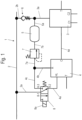
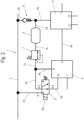
- Figure 1-2 show schematic block diagrams of an embodiment of a brake control device arrangement 1 according to the invention in different operating positions.
- a brake for freight wagons with an air line 2 and an air tank 5 is shown schematically. Other components, such as brake cylinders, etc., are not shown.
- the brake control device arrangement 1 comprises a first brake control device 3, a second brake control device 4, at least one air tank 5, a pressure relief valve 7 and a switching valve 8.
- the first brake control unit 3 is connected to the air line 2 via a line 3a via a check valve 6 and a further line 2b.
- the air tank 5 is connected to the line 3a of the first brake control unit 3 via a line 5a.
- the first brake control unit 3 has two output connections C1, C2 for controlling brake cylinders, which will not be discussed further here.
- the second brake control unit 4 is connected with its HL input pressure connection via a first line 4a to a working connection 8-2 of the switching valve 8.
- a second line 4b connects the R connection of the second brake control unit 4 to a third line 4c of the second brake control unit 4, which is connected to a working connection 8-3 of the switching valve 8.
- a fourth line 4d connects the C-connection of the second brake control unit 4 with the first brake control unit 3.
- a pressure relief valve 7 is connected via a line 7a to the lines 4b and 4c of the second brake control unit 4.
- the pressure relief valve 7 is also connected to the air tank 5 via a further line 7b.
- the switching valve 8 is designed as a 3/2-way valve with an electromagnetic drive 8a ("solenoid valve"). It can also be a pneumatically switchable valve. An input connection 8-1 of the switching valve 8 communicates with the air line 2 via a line 2a.
- Figure 1 shows the first operating position, which is also referred to as the fallback level.
- the air line 2 is operated as a so-called main air line (HL) with a pressure (p HL ) of ⁇ 5 bar.
- the first operating position therefore corresponds to a so-called classic HL control, which is carried out with the second brake control unit 4.
- the switching valve 8 In the first operating position, the switching valve 8 is switched off by means of the drive 8a, i.e. it is de-energized.
- the input connection 8-1 is connected to the working connection 8-2.
- the second brake control unit 4 communicates with its HL connection via the line 4a, the switching valve connections 8-2 and 8-1 and thus via the line 2a with the air line 2.
- the second brake control unit 4 is coupled to the first brake control unit 3 via the line 4d and thus controls the first brake control unit 3 in the first operating position.
- the second brake control unit 4 communicates with the first brake control unit 3 via the line 4d.
- This can be done pneumatically by means of a control pressure or several and/or electrically by means of one or more electrical signals.
- the electrical signals can be analog and/or digital electrical signals.
- the switching valve 8 has a "low-active" safety level. In the de-energized state, i.e. in the first operating position, it is active, i.e. the working connections 8-1 and 8-2 are connected, whereby the second brake control unit 4 is activated.
- the air line 2 in contrast to the first operating position, is operated as a so-called main air tank line (HBL) with a pressure (p HBL ) of approximately 10 bar.
- HBL main air tank line
- p HBL pressure
- the second operating position corresponds to a working position of a so-called 1-line ep (electro-pneumatic) brake, whereby a direct ep brake control is carried out with the first brake control unit 3.
- the Electrical control of the brake control unit 3 in the case of direct EP brake control is known and will not be shown further.
- the second brake control unit 4 is in an inactive mode, with the HL input connection being connected via the line 4a, the connected working connections 8-2, 8-3 of the switching valve 8, the line 4b to the R connection of the second brake control unit 4 and via the pressure relief valve 7 to the air tank 5. In this way, the second brake control unit 4 is always pressurized even in its inactive mode. In this case, this pressure corresponds to the tank pressure of the air tank 5.
- a load correction takes place both in the first operating position and in the second operating position through the respective T-pressure connection in the first brake control unit 3 and in the second brake control unit 4.
- Figure 3 shows a schematic block diagram of a variation of the embodiment according to Figure 1-2 represents.
- Figure 3 shows the second operating position of the brake control device arrangement 1 in a variation in which the working connection 8-3 of the switching valve 8 is neither connected to the line 4b of the switching valve 8 nor to the pressure relief valve 7.
- the working connection 8-3 can be connected to a not shown another pressure source in order to supply the second brake control unit 4 in the inactive state with a pressure at the HL connection of the second brake control unit 4 in this second operating position, so that the second brake control unit 4 can be used immediately at any time from the fallback level.
- the pressure required for this can be taken from a separate and/or additional pressure source (not shown), e.g. from an auxiliary air tank.
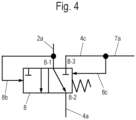
- FIG 4 a schematic block diagram of the switching valve 8 is shown as a pneumatically switchable switching valve 8.
- the pneumatic drive connection of the switching valve 8 is connected via a line 8b to the line 2a (and thus to the air line 2, see Figures 1-3 ).
- a further drive connection is connected via a further line 8c to the line 7a of the pressure relief valve 7, via this to the air tank 5.
- the pneumatically switchable switching valve 8 is pressurized via line 8b and line 2a with the pressure (p HL ) of ⁇ 5 bar of the air line 2 (now operated as HL) compared to the pressure of the air tank of 5 bar in line 8c and switched off.
- the working connections 8-1 and 8-2 of the switching valve 8 are then connected.
- the pneumatically switchable switching valve 8 is actuated via line 8b and line 2a with the pressure (p HBL ) of approx. 10 bar of the air line 2 operated as HBL compared to the pressure of the air tank 5 of 5 bar in line 8c and switched on.
- the working connections 8-2 and 8-3 are as in Figure 1 shown connected.
- Figure 5 is a schematic block diagram of the embodiment according to Figure 1-2 with different controls of the electromagnetic drive 8a of the switching valve 8.
- Figure 5 shows the brake control device arrangement 1 in the second operating position, in which the second brake control device 4 is inactive (see Figure 2 ).
- the different configurations for controlling the electromagnetic drive 8a of the switching valve 8 are shown together, although only one of these configurations is used depending on the application.
- control it is also possible for the control to take place via a bus signal from the leading unit on a continuous bus line 11, wherein the bus line 11 is coupled via a connecting line 11a to an interface 12, which converts the control signal of the bus line 11 into a suitable electrical signal for the drive 8a of the switching valve 8 and makes it available via a connecting line 12a.
- the control signal from the leading unit can also be transmitted via the "normal" bus line 11 via a connecting line 11b to the first brake control unit 3, which has its own interface and transmits a corresponding control signal for the drive 8a of the switching valve 8 to the drive 8a via a control line 3c.
- the first brake control unit 3 can also generate the electrical signal for controlling the drive 8a of the switching valve 8 by a pressure sensor 9.
- the pressure sensor 9 is connected to the air line 2 via a line 2c and, as an HL pressure sensor 9, supplies a corresponding signal, which corresponds to the current pressure of the air line 2, via a signal line 9a to a processing unit 3b of the first brake control unit 3.
- the processing unit 3b can be arranged separately or be part of the first brake control unit 3.
- the processing unit 3b has, for example, processing logic and generates a control signal for the switching valve 8.
- the control signal is provided to the drive 8a of the switching valve 8 via the control line 3c.
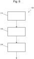
- Figure 6 represents a schematic flow diagram of a method 100 according to the invention for controlling the brake control device arrangement 1.
- a first method step 110 the air line 2 is operated in a first operating position of the brake control device arrangement 1 as a main air line (HL) with a first pressure p HL of ⁇ 5 bar.
- the switching valve 8 is switched off and connects an HL input connection of the second brake control device 4 to the air line 2.
- the second brake control device 4 communicates with the first brake control device 3 and controls this in such a way that a classic HL control is carried out with the second brake control device 4.
- a second method step 120 the switching valve 8 is switched on and adjusts the brake control device arrangement 1 from the first operating position to a second operating position.
- the air line 2 is operated as the main air tank line (HBL) with a second, constant pressure p HBL of approximately 10 bar.
- the HL input connection of the second brake control device 4 is separated from the air line 2 and connected to the air tank 5 via the pressure relief valve 7.
- the first brake control device 3 communicates with the air line 2.
- the second operating position thus corresponds to a working position of a so-called 1-line ep (electro-pneumatic) brake, with direct ep brake control being carried out with the first brake control device 3.
- a third method step 130 the switching valve 8 is switched off again and moves the brake control device arrangement 1 from the second operating position back to the first operating position.
- the HL input connection of the second brake control device 4 with the air tank 5 is interrupted and connected to the air line 2.
- the brake with the brake control device arrangement 1 according to the invention can also be used for passenger carriages or for traction vehicles.
Landscapes
- Engineering & Computer Science (AREA)
- Transportation (AREA)
- Mechanical Engineering (AREA)
- Braking Systems And Boosters (AREA)
Description
- Die Erfindung betrifft eine Bremssteuergeräteanordnung einer Bremse für Schienenfahrzeuge nach dem Oberbegriff des Anspruchs 1. Die Erfindung bezieht sich auch auf ein Verfahren zum Steuern einer Bremssteuergeräteanordnung.
- Eine übliche Bremse weist ein Bremssteuergerät auf. Bremssteuergeräte der Wagen/Fahrzeuge sind in vielen Ausführungen bekannt und steuern eine Füllung von Hilfs- bzw. Vorratsluftbehältern und bilden nach Maßgabe des Druckes in der Hauptluftleitung (HL) oder eines übermittelten Sollwertes einen Vorsteuer- bzw. Bremszylinderdruck.
- Eine übliche Bremse für Schienenfahrzeuge, z.B. für einen Zug bzw. Triebzug wird derzeit entweder über eine Hauptluftleitung (HL) als so genannte "klassische HL-Steuerung", über zwei Leitungen, d.h. über eine Hauptluftleitung (HL) und eine Hauptluftbehälterleitung (HBL) bei elektro-pneumatischen Systemen (ep-Systeme), oder über eine Hauptluftbehälterleitung (HBL) bei direkten ep-Systemen ohne Rückfallebene angesteuert.
- Bei bekannten Systemen mit elektro-pneumatischer Bremse wird für eine pneumatische Rückfallebene immer eine zweite Luftleitung benötigt.
- Aus der
WO 00/24625 A2 - Die Ansteuerung der jeweiligen Komponenten erfolgt hierbei über wenigstens eine lokale, elektronische Bremssteuereinheit.
- Die Aufgabe der Erfindung besteht darin, eine verbesserte Bremssteuergeräteanordnung für eine Bremse für Schienenfahrzeuge und ein Verfahren zum Steuern einer Bremssteuergeräteanordnung zu schaffen.
- Die Aufgabe wird durch die Gegenstände der Ansprüche 1 und 14 gelöst.
- Ein Erfindungsgedanke besteht darin, eine direkte 1-Leitungs-ep-Bremse mit einer Rückfallebene als "klassische HL-Steuerung" zu kombinieren. Mit anderen Worten, in einem Schienenfahrzeug wird eine direkte Bremssystemsteuerung mit einem klassischen Steuerventil als Rückfallebene realisiert, wobei trotzdem nur eine durchgehende Luftleitung anstelle von zwei Luftleitungen durch den Zug benötigt wird.
- Eine erfindungsgemäße Bremssteuergeräteanordnung für Schienenfahrzeuge umfasst eine Luftleitung, ein erstes Bremssteuergerät und mit mindestens einem Luftbehälter. Die Bremssteuergeräteanordnung weist zudem ein zweites Bremssteuergerät, ein Druckbegrenzungsventil und ein Schaltventil auf. Das zweite Bremssteuergerät kommuniziert mit dem ersten Bremssteuergerät.
- Die Luftleitung ist in einer ersten Betriebsstellung der Bremssteuergeräteanordnung als Hauptluftleitung mit einem ersten Druck von ≤ 5 bar betrieben, wenn das zweite Bremssteuergerät mit der Luftleitung durch das ausgeschaltete Schaltventil verbunden ist. Dabei ist das erste Bremssteuergerät durch das zweite Bremssteuergerät derart gesteuert, dass eine klassische HL-Steuerung mit dem zweiten Bremssteuergerät gebildet ist.
- Die Luftleitung ist zudem in einer zweiten Betriebsstellung der Bremssteuergeräteanordnung als Hauptluftbehälterleitung mit einem zweiten, konstanten Druck von ca. 10 bar betrieben, wenn die Bremssteuergeräteanordnung aus der ersten Betriebsstellung in die zweite Betriebsstellung durch das eingeschaltete Schaltventil verstellt ist, wobei die Verbindung des zweiten Bremssteuergerätes mit der Luftleitung unterbrochen und das zweite Bremssteuergerät über das Druckbegrenzungsventil mit dem Luftbehälter verbunden ist, und wobei das erste Bremssteuergerät mit der Luftleitung kommuniziert und eine direkte ep-Bremsensteuerung ausführt.
- Die Bremssteuergeräteanordnung ist zudem aus der zweiten Betriebsstellung zurück in die erste Betriebsstellung durch das ausgeschaltete Schaltventil verstellbar, wobei die Luftleitung wider in der ersten Betriebsstellung der Bremssteuergeräteanordnung als Hauptluftleitung mit dem ersten Druck von ≤ 5 bar betrieben ist.
- Mit dieser Anordnung bzw. Verschaltung und Kommunikation des ersten Bremssteuergeräts mit einem zweiten Bremssteuergerät und einem Schaltventil ergibt sich der Vorteil, dass eine direkte ep-Bremse ohne Verzicht auf deren Vorteile verwendet werden kann, wobei auf eine zweite Luftleitung verzichtet werden kann.
- Ein erfindungsgemäßes Verfahren zum Steuern einer Bremssteuergeräteanordnung einer Bremse für Schienenfahrzeuge mit einer Luftleitung, wobei die Bremssteuergeräteanordnung ein erstes Bremssteuergerät, ein zweites Bremssteuergerät, ein Druckbegrenzungsventil, ein Schaltventil und mindestens einen Luftbehälter aufweist, umfasst die Verfahrensschritte (110) Betreiben der Luftleitung in einer ersten Betriebsstellung der Bremssteuergeräteanordnung als Hauptluftleitung (HL) mit einem ersten Druck (pHL) von ≤ 5 bar, Verbinden des zweiten Bremssteuergerätes mit der Luftleitung durch Ausschalten des Schaltventils, und Steuern des ersten Bremssteuergerätes durch das zweite Bremssteuergerät derart, dass eine klassische HL-Steuerung mit dem zweiten Bremssteuergerät ausgeführt wird; (120) Betreiben der Luftleitung in einer zweiten Betriebsstellung der Bremssteuergeräteanordnung als Hauptluftbehälterleitung (HBL) mit einem zweiten, konstanten Druck (pHBL) von ca. 10 bar, Verstellen der Bremssteuergeräteanordnung aus der ersten Betriebsstellung in die zweite Betriebsstellung durch Einschalten des Schaltventils, wobei die Verbindung des zweiten Bremssteuergerätes mit der Luftleitung unterbrochen wird und das zweite Bremssteuergerät über das Druckbegrenzungsventil mit dem Luftbehälter verbunden wird, und wobei das erste Bremssteuergerät mit der Luftleitung kommuniziert und eine direkte ep-Bremsensteuerung ausführt; (130) Verstellen der Bremssteuergeräteanordnung aus der zweiten Betriebsstellung zurück in die erste Betriebsstellung durch Ausschalten des Schaltventils, wobei wieder ein Betreiben der Luftleitung in der ersten Betriebsstellung der Bremssteuergeräteanordnung als Hauptluftleitung (HL) mit dem ersten Druck (pHL) von ≤ 5 bar erfolgt.
- Mit diesem Verfahren kann eine einfache vorteilhafte Steuerung der Bremssteuergeräteanordnung ermöglicht werden.
- Vorteilhafte Weiterbildungen der Erfindung sind durch die Unteransprüche angegeben.
- Von besonderem Vorteil ist es, wenn das erste Bremssteuergerät als eine direkte ep-Bremssteuereinheit und das zweite Bremssteuergerät als ein klassisches UIC-Steuerventil ausgebildet ist, da in diesem Fall bewährte Funktionseinheiten verwendet werden können.
- Hierzu ist es in einer Ausführung vorteilhaft, wenn das zweite Bremssteuergerät mit dem ersten Bremssteuergerät über eine Leitung verbunden ist, über welche das zweite Bremssteuergerät mit dem ersten Bremssteuergerät pneumatisch oder/und elektrisch kommuniziert. Eine pneumatische Kommunikation kann z.B. mittels eines Steuerdruckes oder mehrerer ausgeführt werden, wobei eine elektrische Kommunikation ein elektrisches analoges oder/und digitales Signal sein kann.
- In einer weiteren Ausführung ist das zweite Bremssteuergerät mit Arbeitsanschlüssen des Schaltventils und mit dem Druckbegrenzungsventil verbunden. Dies ergibt eine einfache Steuerung für das zweite Bremssteuergerät.
- Dabei ist es vorgesehen, dass das Schaltventil mit einem Eingangsanschluss mit der Luftleitung verbunden ist. Damit wird eine vorteilhafte schaltbare Verbindung des zweiten Bremssteuergeräts mit der Luftleitung ermöglicht.
- Es ist zudem vorteilhaft, wenn die Bremssteuergeräteanordnung aus einer ersten Betriebsstellung, in welcher die Luftleitung mit einem ersten Druck (pHL) betrieben wird, in eine zweite Betriebsstellung, in welcher die Luftleitung mit einem zweiten Druck (pHBL) betrieben wird, der zu dem ersten Druck unterschiedlich ist, mittels des Schaltventils verstellbar ist. Die einzige Luftleitung wird je nach Betriebszustand vom führenden Fahrzeug als "klassische" Hauptluftleitung (HL) als Rückfallebene mit einem ersten Druck pHL von ≤ 5 bar oder als Hauptluftbehälterleitung (HBL) mit einem zweiten, konstanten Druck pHBL von ca. 10 bar betrieben. Abhängig von diesen Druckwerten kann die Bremssteuergeräteanordnung vorteilhaft aus einer ersten Betriebsstellung in eine zweite Betriebsstellung und zurück von dem Schaltventil verstellt werden.
- In einer Ausführung ist vorgesehen, dass das Schaltventil in der zweiten Betriebsstellung eingeschaltet ist, und dass das Schaltventil in der ersten Betriebsstellung ausgeschaltet ist. Auf diese Weise ergibt sich der Vorteil, dass das Schaltventil in der ersten Betriebsstellung in der Rückfallebene in seiner Ausgangsstellung steht, z.B. als Magnetventil stromlos ist.
- In einer weiteren Ausführung ist in der zweiten Betriebsstellung ein HL-Eingangsdruck-Anschluss des zweiten Bremssteuergeräts über die Arbeitsanschlüsse des Schaltventils mit einem Druck beaufschlagt, wobei das zweite Bremssteuergerät inaktiv ist. Dabei ist besonders vorteilhaft, dass das zweite Bremssteuergerät auch in diesem inaktiven Betrieb, d.h. in der zweiten Betriebsstellung, wenn die Funktion der direkten ep-Bremse über das erste Bremssteuergerät realisiert ist, immer mit Druck beaufschlagt wird.
- Dies kann z.B. in einer weiteren Ausführung dadurch ausgeführt werden, indem der HL-Eingangsdruck-Anschluss des zweiten Bremssteuergeräts in der zweiten Betriebsstellung über das Druckbegrenzungsventil mit dem Luftbehälter verbunden ist. Damit ergibt sich der Vorteil, dass das zweite Bremssteuergerät aus einer Rückfallebene jederzeit sofort einsetzbar ist.
- Es ist in einer weiteren Ausführung vorgesehen, dass in der ersten Betriebsstellung der HL-Eingangsdruck-Anschluss des zweiten Bremssteuergeräts über die Arbeitsanschlüsse des Schaltventils mit der Luftleitung verbunden ist, wobei das zweite Bremssteuergerät aktiv ist.
- Eine Lastkorrektur sowohl in der ersten als auch zweiten Betriebsstellung findet jeweils parallel durch einen jeweiligen T-Druck-Anschluss sowohl in dem ersten als auch in dem zweiten Bremssteuergerät statt.
- Das Schaltventil kann in einer Ausführung einen elektromagnetischen Antrieb aufweisen. Alternativ kann das Schaltventil einen pneumatischen Antrieb aufweisen. Derartige Schaltventile sind vorteilhaft marktüblich und mit hohem Qualitätsstandard kostengünstig verfügbar.
- Es ist zudem vorteilhaft, wenn das Schaltventil ein 3/2-Wege-Ventil ist, da dies ein kostengünstiges Standardbauteil mit hoher Qualität ist.
- In einer Ausführung kann die Bremse eine Güterwagenbremse sein. Dies ist vorteilhaft, da trotz einer einzigen Luftleitung die Vorteile einer direkten ep-Bremse genutzt werden können.
- Es ist zudem vorteilhaft, dass die Bremse auch eine Reisezugwagenbremse sein kann, da sich so ein Einsatzbereich vergrößert.
- In einer noch weiteren Ausführung ist das Schaltventil in Ausführung als Magnetventil von einer Lokomotive oder einem Triebfahrzeug direkt über eine separate Steuerleitung oder/und über eine Busleitung über eine Schnittstelle oder/und über die Busleitung über das erste Bremssteuergerät angesteuert. Hiermit werden vorteilhafte unterschiedliche Ansteuerungsmöglichkeiten realisiert.
- Alternativ oder zusätzlich ist es auch möglich, dass das Schaltventil in Ausführung als Magnetventil von dem ersten Bremssteuergerät, welches mit einem mit der Luftleitung kommunizierenden Drucksensor verbunden ist, in Abhängigkeit von dem aktuellen Druck der Luftleitung angesteuert ist. Damit kann auf eine zusätzliche durchgehende Steuerleitung verzichtet werden.
- Ein Ausführungsbeispiel der Erfindung wird nachfolgend anhand der beigefügten Zeichnungen beschrieben.
- Es zeigen:
- Figur 1-2
- schematische Blockschaltbilder eines Ausführungsbeispiels einer erfindungsgemäßen Bremssteuergeräteanordnung in unterschiedlichen Betriebsstellungen;
- Figur 3
- ein schematisches Blockschaltbild einer Variation des Ausführungsbeispiels nach
Figur 1-2 ; - Figur 4
- ein schematisches Blockschaltbild eines Schaltventils;
- Figur 5
- ein schematisches Blockschaltbild des Ausführungsbeispiels nach
Figur 1-2 mit unterschiedlichen Ansteuerungen; und - Figur 6
- ein schematisches Flussdiagramm eines erfindungsgemäßen Verfahrens zum Steuern der Bremssteuergeräteanordnung nach
Figur 1-2 . -
Figur 1-2 zeigen schematische Blockschaltbilder eines Ausführungsbeispiels einer erfindungsgemäßen Bremssteuergeräteanordnung 1 in unterschiedlichen Betriebsstellungen. - In dem gezeigten Beispiel ist eine Bremse für Güterwagen mit einer Luftleitung 2 und einem Luftbehälter 5 schematisch dargestellt. Weitere Komponenten, wie z.B. Bremszylinder usw., sind nicht gezeigt.
- Die Bremssteuergeräteanordnung 1 umfasst ein erstes Bremssteuergerät 3, ein zweites Bremssteuergerät 4, mindestens einen Luftbehälter 5, ein Druckbegrenzungsventil 7 und ein Schaltventil 8.
- Das erste Bremssteuergerät 3 ist über eine Leitung 3a über ein Rückschlagventil 6 und eine weitere Leitung 2b mit der Luftleitung 2 verbunden. Zudem ist der Luftbehälter 5 mit einer Leitung 5a an der Leitung 3a des ersten Bremssteuergeräts 3 angeschlossen.
- Das erste Bremssteuergerät 3 weist zwei Ausgangsanschlüsse C1, C2 zur Ansteuerung von Bremszylindern auf, worauf hier nicht weiter eingegangen wird.
- Das zweite Bremssteuergerät 4 ist mit seinem HL-Eingangsdruck-Anschluss über eine erste Leitung 4a mit einem Arbeitsanschluss 8-2 des Schaltventils 8 verbunden. Eine zweite Leitung 4b verbindet den R-Anschluss des zweiten Bremssteuergeräts 4 mit einer dritten Leitung 4c des zweiten Bremssteuergeräts 4, welche mit einem Arbeitsanschluss 8-3 des Schaltventils 8 verbunden ist.
- Eine vierte Leitung 4d verbindet den C-Anschluss des zweiten Bremssteuergeräts 4 mit dem ersten Bremssteuergerät 3.
- Ein Druckbegrenzungsventil 7 ist über eine Leitung 7a mit den Leitungen 4b und 4c des zweiten Bremssteuergeräts 4 verbunden. Das Druckbegrenzungsventil 7 ist zudem über eine weitere Leitung 7b an dem Luftbehälter 5 angeschlossen.
- Das Schaltventil 8 ist in dem gezeigten Beispiel als ein 3/2-Wege-Ventil mit einem elektromagnetischen Antrieb 8a ("Magnetventil") ausgebildet. Es kann auch ein pneumatisch schaltbares Ventil sein. Ein Eingangsanschluss 8-1 des Schaltventils 8 kommuniziert über eine Leitung 2a mit der Luftleitung 2.
- Mittels des Schaltventils 8 ist es möglich, die Bremssteuergeräteanordnung 1 aus der ersten Betriebsstellung in eine zweite Betriebsstellung, die unten noch erläutert wird, und zurück zu verstellen.
-
Figur 1 zeigt die erste Betriebsstellung, die auch als Rückfallebene bezeichnet wird. In der ersten Betriebsstellung wird die Luftleitung 2 als eine so genannte Hauptluftleitung (HL) mit einem Druck (pHL) von ≤ 5 bar betrieben. - Damit entspricht die erste Betriebsstellung einer so genannten klassischen HL-Steuerung, die mit dem zweiten Bremssteuergerät 4 ausgeführt wird.
- In der ersten Betriebsstellung ist das Schaltventil 8 mittels des Antriebs 8a ausgeschaltet, d.h. stromlos. Dabei ist der Eingangsanschluss 8-1 mit dem Arbeitsanschluss 8-2 verbunden.
- Auf diese Weise kommuniziert in der Rückfallebene nur das zweite Bremssteuergerät 4 mit seinem HL-Anschluss über die Leitung 4a, die Schaltventilanschlüsse 8-2 und 8-1 und somit über die Leitung 2a mit der Luftleitung 2. Mittels der Leitung 4d ist das zweite Bremssteuergerät 4 mit dem ersten Bremssteuergerät 3 gekoppelt und steuert somit das erste Bremssteuergerät 3 in der ersten Betriebsstellung. Mit anderen Worten, das zweite Bremssteuergerät 4 kommuniziert mit dem ersten Bremssteuergerät 3 über die Leitung 4d. Dies kann pneumatisch mittels eines Steuerdruckes oder mehrerer oder/und elektrisch mittels eines oder mehrerer elektrischer Signale erfolgen. Die elektrischen Signale können analoge oder/und digitale elektrische Signale sein.
- Das Schaltventil 8 weist eine Sicherheitsebene "low-aktiv" auf. Im stromlosen Zustand, also in der ersten Betriebsstellung, ist es aktiv, d.h. die Arbeitsanschlüsse 8-1 und 8-2 sind verbunden, wobei das zweite Bremssteuergerät 4 aktiviert ist.
- In der in
Figur 2 gezeigten zweiten Betriebsstellung wird die Luftleitung 2 im Gegensatz zu der ersten Betriebsstellung als eine so genannte Hauptluftbehälterleitung (HBL) mit einem Druck (pHBL) von ca. 10 bar betrieben. - Damit entspricht die zweite Betriebsstellung einer Arbeitsstellung einer so genannten 1-Leitungs-ep(elektro-pneumatischen)-Bremse, wobei eine direkte ep-Bremsensteuerung mit dem ersten Bremssteuergerät 3 ausgeführt wird. Die elektrische Ansteuerung des Bremssteuergeräts 3 im Fall der direkten ep-Bremsensteuerung ist bekannt und wird nicht weiter gezeigt.
- In der zweiten Betriebsstellung gemäß
Figur 2 im Gegensatz zu der ersten Betriebsstellung nachFigur 1 ist das Schaltventil 8 mittels des Antriebs 8a eingeschaltet. Das heißt, dass der Eingangsanschluss 8-1 geschlossen ist und die Arbeitsanschlüsse 8-2 und 8-3 verbunden sind. - Da der Eingangsanschluss 1 geschlossen ist, kommuniziert nur das erste Bremssteuergerät 3 über seine Leitung 3a und das Rückschlagventil 6 mit der Luftleitung 2.
- Das zweite Bremssteuergerät 4 ist in einem inaktiven Betrieb, wobei der HL-Eingangsanschluss über die Leitung 4a, die verbundenen Arbeitsanschlüsse 8-2, 8-3 des Schaltventils 8, die Leitung 4b mit dem R-Anschluss des zweiten Bremssteuergeräts 4 und über das Druckbegrenzungsventil 7 mit dem Luftbehälter 5 verbunden ist. Auf diese Weise ist das zweite Bremssteuergerät 4 auch in seinem inaktiven Betrieb immer mit Druck beaufschlagt. Dieser Druck entspricht in diesem Fall dem Behälterdruck des Luftbehälters 5.
- Daraus ergibt sich der Vorteil, dass in der zweiten Betriebsstellung das zweite Bremssteuergerät 4 aus der Rückfallebene sofort einsetzbar ist.
- Auf diese Weise kann mit der erfindungsgemäßen Bremssteuergeräteanordnung 1 auf eine zweite Luftleitung, die in üblichen Systemen mit ep-Bremse immer erforderlich ist, verzichtet werden, ohne die Vorteile einer direkten ep-Bremse aufzugeben.
- Eine Lastkorrektur findet sowohl in der ersten Betriebsstellung als auch in der zweiten Betriebsstellung durch den jeweiligen T-Druck-Anschluss im ersten Bremssteuergerät 3 als auch im zweiten Bremssteuergerät 4 statt.
-
Figur 3 stellt ein schematisches Blockschaltbild einer Variation des Ausführungsbeispiels nachFigur 1-2 dar. -
Figur 3 zeigt die zweite Betriebsstellung der Bremssteuergeräteanordnung 1 in einer Variation, in welcher der Arbeitsanschluss 8-3 des Schaltventils 8 weder mit der Leitung 4b des Schaltventils 8 noch mit dem Druckbegrenzungsventil 7 verbunden ist. In diesem Fall kann der Arbeitsanschluss 8-3 mit einer nicht gezeigten anderen Druckquelle verbunden sein, um in dieser zweiten Betriebsstellung das zweite Bremssteuergerät 4 im inaktiven Zustand mit einem Druck an dem HL-Anschluss des zweiten Bremssteuergerät 4 zu versorgen, damit das zweite Bremssteuergerät 4 aus der Rückfallebene jederzeit sofort einsetzbar ist. Der dazu erforderliche Druck kann hier aus einer nicht gezeigten, separaten und/oder zusätzlichen Druckquelle entnommen werden, z.B. aus einem Hilfsluftbehälter. - In
Figur 4 ist ein schematisches Blockschaltbild des Schaltventils 8 als ein pneumatisch schaltbares Schaltventil 8 gezeigt. - Der pneumatische Antriebsanschluss des Schaltventils 8 ist über eine Leitung 8b mit der Leitung 2a (und so mit der Luftleitung 2, siehe
Figuren 1-3 ) verbunden. Ein weiterer Antriebsanschluss ist über eine weitere Leitung 8c an der Leitung 7a des Druckbegrenzungsventils 7, über dieses an den Luftbehälter 5 angeschlossen. - In der ersten Betriebsstellung ist das pneumatisch schaltbare Schaltventil 8 über die Leitung 8b und die Leitung 2a mit dem Druck (pHL) von ≤ 5 bar der Luftleitung 2 (nun als HL betrieben) gegenüber dem Druck des Luftbehälters von 5 bar in der Leitung 8c beaufschlagt und ausgeschaltet. Die Arbeitsanschlüsse 8-1 und 8-2 des Schaltventils 8 sind dann verbunden.
- In der zweiten Betriebsstellung ist das pneumatisch schaltbare Schaltventil 8 über die Leitung 8b und die Leitung 2a mit dem Druck (pHBL) von ca. 10 bar der als HBL betriebenen Luftleitung 2 gegenüber dem Druck des Luftbehälters 5 von 5 bar in der Leitung 8c beaufschlagt und eingeschaltet. In diesem eingeschalteten Zustand sind die Arbeitsanschlüsse 8-2 und 8-3 wie in
Figur 1 dargestellt verbunden. - In
Figur 5 ist ein schematisches Blockschaltbild des Ausführungsbeispiels nachFigur 1-2 mit unterschiedlichen Ansteuerungen des elektromagnetischen Antriebs 8a des Schaltventils 8 dargestellt. -
Figur 5 zeigt die Bremssteuergeräteanordnung 1 in der zweiten Betriebsstellung, in welcher das zweite Bremssteuergerät 4 inaktiv ist (sieheFigur 2 ). Die unterschiedlichen Konfigurationen der Ansteuerung des elektromagnetischen Antriebs 8a des Schaltventils 8 sind gemeinsam gezeigt, wobei jedoch nur eine von diesen Konfigurationen je nach Einsatzfall verwendet wird. - Das Schaltventil 8 in Ausführung als Magnetventil mit dem Antrieb 8a kann von einer führenden Einheit (z.B. Lokomotive bzw. Triebfahrzeug), der ein Zug mit Güterwagen mit der oben beschriebenen Güterwagenbremse mit der erfindungsgemäßen Bremssteuergeräteanordnung 1 zugeordnet ist, direkt über eine (durch alle Wagen des Zugs durchgehende) separate Steuerleitung 10 über einen Anschluss 10a angesteuert werden. Es ist möglich, dass auch ein Zug mit Reisezugwagen oder ein kombinierter Zug mit Reisezugwagen und Güterwagen (z.B. Autoreisezug) mit der erfindungsgemäßen Bremssteuergeräteanordnung 1 ausgestattet werden kann.
- Es ist auch möglich, dass die Ansteuerung über ein Bussignal von der führenden Einheit auf einer durchgehenden Busleitung 11 erfolgt, wobei die Busleitung 11 über eine Anschlussleitung 11a mit einer Schnittstelle 12 gekoppelt ist, die das Ansteuersignal der Busleitung 11 in ein passendes elektrisches Signal für den Antrieb 8a des Schaltventils 8 umwandelt und über eine Anschlussleitung 12a zur Verfügung stellt.
- Das Ansteuersignal von der führenden Einheit kann auch über die "normale" Busleitung 11 über eine Anschlussleitung 11b zunächst an das erste Bremssteuergerät 3 geleitet werden, das eine eigene Schnittstelle besitzt und ein entsprechendes Ansteuersignal für den Antrieb 8a des Schaltventils 8 über eine Steuerleitung 3c dem Antrieb 8a zuleitet.
- Andererseits kann das erste Bremssteuergerät 3 das elektrische Signal zur Ansteuerung des Antriebs 8a des Schaltventils 8 auch durch einen Drucksensor 9 generiert werden. Dabei ist der Drucksensor 9 über eine Leitung 2c mit der Luftleitung 2 verbunden und liefert als HL-Drucksensor 9 ein entsprechendes Signal, welches dem aktuellen Druck der Luftleitung 2 entspricht, über eine Signalleitung 9a an eine Verarbeitungseinheit 3b des ersten Bremssteuergeräts 3. Die Verarbeitungseinheit 3b kann separat angeordnet oder Bestandteil des ersten Bremssteuergeräts 3 sein. Die Verarbeitungseinheit 3b weist beispielsweise eine Verarbeitungslogik auf und erzeugt ein Ansteuerungssignal für das Schaltventil 8. Das Ansteuerungssignal wird dem Antrieb 8a des Schaltventils 8 über die Steuerleitung 3c bereitgestellt.
-
Figur 6 stellt ein schematisches Flussdiagramm eines erfindungsgemäßen Verfahrens 100 zum Steuern der Bremssteuergeräteanordnung 1 dar. - In einem ersten Verfahrensschritt 110 wird die Luftleitung 2 in einer ersten Betriebsstellung der Bremssteuergeräteanordnung 1 als Hauptluftleitung (HL) mit einem ersten Druck pHL von ≤ 5 bar betrieben. Das Schaltventil 8 ist ausgeschaltet und verbindet einen HL-Eingangsanschluss des zweiten Bremssteuergerätes 4 mit der Luftleitung 2. Das zweite Bremssteuergerät 4 kommuniziert mit dem ersten Bremssteuergerät 3 und steuert dies derart, dass eine klassische HL-Steuerung mit dem zweiten Bremssteuergerät 4 ausgeführt wird.
- In einem zweiten Verfahrensschritt 120 wird das Schaltventil 8 eingeschaltet und verstellt die Bremssteuergeräteanordnung 1 aus der ersten Betriebsstellung in eine zweite Betriebsstellung. Die Luftleitung 2 wird als Hauptluftbehälterleitung (HBL) mit einem zweiten, konstanten Druck pHBL von ca. 10 bar betrieben. Der HL-Eingangsanschluss des zweiten Bremssteuergerätes 4 wird von der Luftleitung 2 getrennt und über das Druckbegrenzungsventil 7 mit dem Luftbehälter 5 verbunden. Das erste Bremssteuergerät 3 kommuniziert mit der Luftleitung 2. Damit entspricht die zweite Betriebsstellung einer Arbeitsstellung einer so genannten 1-Leitungs-ep(elektro-pneumatischen)-Bremse, wobei eine direkte ep-Bremsensteuerung mit dem ersten Bremssteuergerät 3 ausgeführt wird.
- In einem dritten Verfahrensschritt 130 wird das Schaltventil 8 wieder ausgeschaltet und verstellt die Bremssteuergeräteanordnung 1 aus der zweiten Betriebsstellung zurück in die erste Betriebsstellung. Der HL-Eingangsanschluss des zweiten Bremssteuergerätes 4 mit dem Luftbehälter 5 wird unterbrochen und mit der Luftleitung 2 verbunden.
- Die Erfindung ist durch das oben angegebene Ausführungsbeispiel nicht eingeschränkt, sondern im Rahmen der Ansprüche modifizierbar.
- So ist z.B. denkbar, dass die Bremse mit der erfindungsgemäßen Bremssteuergeräteanordnung 1 auch für Reisezugwagen/Personenzugwagen oder für Triebfahrzeuge verwendet werden kann.
-
- 1
- Bremssteuergeräteanordnung
- 2
- Luftleitung
- 3
- Erstes Bremssteuergerät
- 3a
- Leitung
- 3b
- Verarbeitungseinheit
- 3c
- Steuerleitung
- 4
- Zweites Bremssteuergerät
- 4a, 4b, 4c, 4d
- Leitung
- 5
- Luftbehälter
- 5a
- Leitung
- 6
- Rückschlagventil
- 7
- Reduzierventil
- 7a, 7b
- Leitung
- 8
- Schaltventil
- 8a
- Antrieb
- 8b, 8c
- Leitung
- 8-1
- Eingangsanschluss
- 8-2, 8-3
- Arbeitsanschluss
- 9
- Drucksensor
- 9a
- Leitung
- 10
- Signalleitung
- 10a .
- Anschlussleitung
- 11
- Busleitung
- 11a, 11b
- Anschlussleitung
- 12
- Schnittstelle
- 12a
- Anschlussleitung
- 100
- Verfahren
- 110, 120, 130
- Verfahrensschritt
Claims (14)
- Bremssteuergeräteanordnung (1) einer Bremse für Schienenfahrzeuge, mit einer Luftleitung (2), einem ersten Bremssteuergerät (3), mindestens einem Luftbehälter (5), einem zweiten Bremssteuergerät (4), einem Druckbegrenzungsventil (7) und einem Schaltventil (8), wobei das zweite Bremssteuergerät (4) mit dem ersten Bremssteuergerät (3) kommuniziert
dadurch gekennzeichnet, dassa) die Luftleitung (2) in einer ersten Betriebsstellung der Bremssteuergeräteanordnung (1) als Hauptluftleitung (HL) mit einem ersten Druck (pHL) von ≤ 5 bar betrieben ist, wenn das zweite Bremssteuergerät (4) mit der Luftleitung (2) durch das ausgeschaltete Schaltventil (8) verbunden ist, und das erste Bremssteuergerät (3) durch das zweite Bremssteuergerät (4) derart gesteuert ist, dass eine klassische HL-Steuerung mit dem zweiten Bremssteuergerät (4) gebildet ist;b) die Luftleitung (2) in einer zweiten Betriebsstellung der Bremssteuergeräteanordnung (1) als Hauptluftbehälterleitung (HBL) mit einem zweiten, konstanten Druck (pHBL) von ca. 10 bar betrieben ist, wenn die Bremssteuergeräteanordnung (1) aus der ersten Betriebsstellung in die zweite Betriebsstellung durch das eingeschaltete Schaltventil (8) verstellt ist, wobei die Verbindung des zweiten Bremssteuergerätes (4) mit der Luftleitung (2) unterbrochen und das zweite Bremssteuergerät (4) über das Druckbegrenzungsventil (7) mit dem Luftbehälter (5) verbunden ist, und wobei das erste Bremssteuergerät (3) mit der Luftleitung (2) kommuniziert und eine direkte ep-Bremsensteuerung ausführt; undc) die Bremssteuergeräteanordnung (1) aus der zweiten Betriebsstellung zurück in die erste Betriebsstellung durch das ausgeschaltete Schaltventil (8) verstellbar ist, wobei die Luftleitung (2) wieder in der ersten Betriebsstellung der Bremssteuergeräteanordnung (1) als Hauptluftleitung (HL) mit dem ersten Druck (pHL) von ≤ 5 bar betrieben ist. - Bremssteuergeräteanordnung (1) nach Anspruch 1, dadurch gekennzeichnet, dass das zweite Bremssteuergerät (4) mit dem ersten Bremssteuergerät (3) über eine Leitung (4d) verbunden ist, über welche das zweite Bremssteuergerät (4) mit dem ersten Bremssteuergerät (3) pneumatisch oder/und elektrisch kommuniziert.
- Bremssteuergeräteanordnung (1) nach Anspruch 1 oder 2, dadurch gekennzeichnet, dass das zweite Bremssteuergerät (4) mit Arbeitsanschlüssen (8-2, 8-3) des Schaltventils (8) und mit dem Druckbegrenzungsventil (7) verbunden ist, wobei das Schaltventil (8) mit einem Eingangsanschluss (8-1) mit der Luftleitung (2) verbunden ist.
- Bremssteuergeräteanordnung (1) nach einem der vorhergehenden Ansprüche, dadurch gekennzeichnet, dass die Bremssteuergeräteanordnung (1) aus einer ersten Betriebsstellung, in welcher die Luftleitung (2) mit einem ersten Druck (pHL) betrieben wird, in eine zweite Betriebsstellung, in welcher die Luftleitung (2) mit einem zweiten Druck (pHBL) betrieben wird, der zu dem ersten Druck unterschiedlich ist, mittels des Schaltventils (8) verstellbar ist.
- Bremssteuergeräteanordnung (1) nach Anspruch 4, dadurch gekennzeichnet, dass das Schaltventil (8) in der ersten Betriebsstellung ausgeschaltet ist, und dass das Schaltventil (8) in der zweiten Betriebsstellung eingeschaltet ist.
- Bremssteuergeräteanordnung (1) nach Anspruch 5, dadurch gekennzeichnet, dass in der zweiten Betriebsstellung ein HL-Eingangsdruck-Anschluss des zweiten Bremssteuergeräts (4) über die Arbeitsanschlüsse (8-2, 8-3) des Schaltventils (8) mit einem Druck beaufschlagt ist, wobei das zweite Bremssteuergerät (4) inaktiv ist.
- Bremssteuergeräteanordnung (1) nach Anspruch 6, dadurch gekennzeichnet, dass der HL-Eingangsdruck-Anschluss des zweiten Bremssteuergeräts (4) in der zweiten Betriebsstellung über das Druckbegrenzungsventil (7) mit dem Luftbehälter (5) verbunden ist.
- Bremssteuergeräteanordnung (1) nach einem der Ansprüche 6 bis 7, dadurch gekennzeichnet, dass in der ersten Betriebsstellung der HL-Eingangsdruck-Anschluss des zweiten Bremssteuergeräts (4) über die Arbeitsanschlüsse (8-1, 8-2) des Schaltventils (8) mit der Luftleitung (2) verbunden ist, wobei das zweite Bremssteuergerät (4) aktiv ist.
- Bremssteuergeräteanordnung (1) nach einem der vorhergehenden Ansprüche, dadurch gekennzeichnet, dass das Schaltventil (8) einen elektromagnetischen Antrieb oder/und einen pneumatischen Antrieb aufweist.
- Bremssteuergeräteanordnung (1) nach einem der vorhergehenden Ansprüche, dadurch gekennzeichnet, dass das Schaltventil (8) ein 3/2-WegeVentil ist.
- Bremssteuergeräteanordnung (1) nach einem der vorhergehenden Ansprüche, dadurch gekennzeichnet, dass die Bremse eine Güterwagenbremse oder eine Reisezugwagenbremse ist.
- Bremssteuergeräteanordnung (1) nach einem der vorhergehenden Ansprüche, dadurch gekennzeichnet, dass das Schaltventil (8) in Ausführung als Magnetventil von einer führenden Einheit direkt über eine separate Steuerleitung (10) oder/und über eine Busleitung (11) über eine Schnittstelle (12) oder/und über die Busleitung (11) über das erste Bremssteuergerät (3) angesteuert ist.
- Bremssteuergeräteanordnung (1) nach einem der Ansprüche 1 bis 11, dadurch gekennzeichnet, dass das Schaltventil (8) in Ausführung als Magnetventil von dem ersten Bremssteuergerät (3), welches mit einem mit der Luftleitung (2) kommunizierenden Drucksensor (9) verbunden ist, in Abhängigkeit von dem aktuellen Druck der Luftleitung (2) angesteuert ist.
- Verfahren (100) zum Steuern einer Bremssteuergeräteanordnung (1) einer Bremse für Schienenfahrzeuge mit einer Luftleitung (2), wobei die Bremssteuergeräteanordnung (1) ein erstes Bremssteuergerät (3), ein zweites Bremssteuergerät (4), ein Druckbegrenzungsventil (7), ein Schaltventil (8) und mindestens einen Luftbehälter (5) aufweist,
gekennzeichnet durch die Verfahrensschritte(110) Betreiben der Luftleitung (2) in einer ersten Betriebsstellung der Bremssteuergeräteanordnung (1) als Hauptluftleitung (HL) mit einem ersten Druck (pHL) von ≤ 5 bar, Verbinden des zweiten Bremssteuergerätes (4) mit der Luftleitung (2) durch Ausschalten des Schaltventils (8), und Steuern des ersten Bremssteuergerätes (3) durch das zweite Bremssteuergerät (4) derart, dass eine klassische HL-Steuerung mit dem zweiten Bremssteuergerät (4) ausgeführt wird;(120) Betreiben der Luftleitung (2) in einer zweiten Betriebsstellung der Bremssteuergeräteanordnung (1) als Hauptluftbehälterleitung (HBL) mit einem zweiten, konstanten Druck (pHBL) von ca. 10 bar, Verstellen der Bremssteuergeräteanordnung (1) aus der ersten Betriebsstellung in die zweite Betriebsstellung durch Einschalten des Schaltventils (8), wobei die Verbindung des zweiten Bremssteuergerätes (4) mit der Luftleitung (2) unterbrochen wird und das zweite Bremssteuergerät (4) über das Druckbegrenzungsventil (7) mit dem Luftbehälter (5) verbunden wird, und wobei das erste Bremssteuergerät (3) mit der Luftleitung (2) kommuniziert und eine direkte ep-Bremsensteuerung ausführt;(130) Verstellen der Bremssteuergeräteanordnung (1) aus der zweiten Betriebsstellung zurück in die erste Betriebsstellung durch Ausschalten des Schaltventils (8), wobei wieder ein Betreiben der Luftleitung (2) in der ersten Betriebsstellung der Bremssteuergeräteanordnung (1) als Hauptluftleitung (HL) mit dem ersten Druck (pHL) von ≤ 5 bar erfolgt.
Applications Claiming Priority (2)
| Application Number | Priority Date | Filing Date | Title |
|---|---|---|---|
| DE102019103179.6A DE102019103179A1 (de) | 2019-02-08 | 2019-02-08 | Bremse für Schienenfahrzeuge, Bremssteuergeräteanordnung und Verfahren zum Steuern einer Bremssteuergeräteanordnung |
| PCT/EP2020/051483 WO2020160902A1 (de) | 2019-02-08 | 2020-01-22 | Bremse für schienenfahrzeuge, bremssteuergeräteanordnung und verfahren zum steuern einer bremssteuergeräteanordnung |
Publications (2)
| Publication Number | Publication Date |
|---|---|
| EP3921212A1 EP3921212A1 (de) | 2021-12-15 |
| EP3921212B1 true EP3921212B1 (de) | 2024-11-27 |
Family
ID=69192056
Family Applications (1)
| Application Number | Title | Priority Date | Filing Date |
|---|---|---|---|
| EP20701961.3A Active EP3921212B1 (de) | 2019-02-08 | 2020-01-22 | Bremssteuergeräteanordnung und verfahren zum steuern einer bremssteuergeräteanordnung einer bremse für schienenfahrzeuge |
Country Status (6)
| Country | Link |
|---|---|
| EP (1) | EP3921212B1 (de) |
| CN (1) | CN113396090B (de) |
| DE (1) | DE102019103179A1 (de) |
| FI (1) | FI3921212T3 (de) |
| PL (1) | PL3921212T3 (de) |
| WO (1) | WO2020160902A1 (de) |
Family Cites Families (6)
| Publication number | Priority date | Publication date | Assignee | Title |
|---|---|---|---|---|
| ATE374138T1 (de) * | 1998-10-23 | 2007-10-15 | Knorr Bremse Systeme | Bremssystem für ein schienenfahrzeug |
| DE19848990A1 (de) * | 1998-10-23 | 2000-04-27 | Knorr Bremse Systeme | Bremssystem für ein Schienenfahrzeug |
| DE102005054089C5 (de) * | 2005-11-12 | 2012-04-12 | Haldex Brake Products Gmbh | Steuergerät für eine Druckluftbremsanlage eines Kraftfahrzeugs |
| DE102014103840A1 (de) * | 2014-03-20 | 2015-09-24 | Knorr-Bremse Systeme für Schienenfahrzeuge GmbH | Druckluftbremsanordnung für ein Schienenfahrzeug |
| DE102016100526A1 (de) * | 2016-01-14 | 2017-07-20 | Knorr-Bremse Systeme für Nutzfahrzeuge GmbH | Steuervorrichtung zum Steuern einer Bremsanlage für ein Fahrzeug, Bremsanlage für ein Fahrzeug, Verfahren zum Betreiben einer Steuervorrichtung und Verfahren zum Beaufschlagen zumindest einer Bremseinrichtung einer Bremsanlage für ein Fahrzeug mit einem Bremsdruck |
| DE102017208840C5 (de) * | 2017-05-24 | 2022-12-08 | Knorr-Bremse Systeme für Schienenfahrzeuge GmbH | Bremsvorrichtung und Verfahren zum Durchführen einer Notbremsung eines Schienenfahrzeugs |
-
2019
- 2019-02-08 DE DE102019103179.6A patent/DE102019103179A1/de active Pending
-
2020
- 2020-01-22 CN CN202080012965.6A patent/CN113396090B/zh active Active
- 2020-01-22 WO PCT/EP2020/051483 patent/WO2020160902A1/de not_active Ceased
- 2020-01-22 EP EP20701961.3A patent/EP3921212B1/de active Active
- 2020-01-22 FI FIEP20701961.3T patent/FI3921212T3/fi active
- 2020-01-22 PL PL20701961.3T patent/PL3921212T3/pl unknown
Also Published As
| Publication number | Publication date |
|---|---|
| CN113396090B (zh) | 2025-03-18 |
| DE102019103179A1 (de) | 2020-08-13 |
| PL3921212T3 (pl) | 2025-03-24 |
| CN113396090A (zh) | 2021-09-14 |
| EP3921212A1 (de) | 2021-12-15 |
| WO2020160902A1 (de) | 2020-08-13 |
| FI3921212T3 (fi) | 2025-02-12 |
Similar Documents
| Publication | Publication Date | Title |
|---|---|---|
| EP3600993B1 (de) | Elektronisch steuerbares bremssystem sowie verfahren zum steuern des elektronisch steuerbaren bremssystems | |
| EP3600995B1 (de) | Elektronisch steuerbares bremssystem sowie verfahren zum steuern des elektronisch steuerbaren bremssystems | |
| EP2055542B1 (de) | Druckmittelbetätigte Bremseinrichtung eines Zugfahrzeugs mit einem gegenläufige Drücke für Anhängerbremsen erzeugenden Festellbremsmodul | |
| EP2133250B1 (de) | Parkbremsventilanordnung für ein Bremssystem eines Nutzfahrzeuges | |
| EP2331377B1 (de) | Feststellbremsanlage | |
| DE102008048207B4 (de) | Elektrisch betätigbare Bremseinrichtung und Verfahren zum Betrieb derselben | |
| EP4069559B1 (de) | Monostabil und fehlertolerant ausgelegte feststellbremsventilanordnung | |
| EP3022099B1 (de) | Feststellbremseinrichtung für ein zugfahrzeug einer zugfahrzeug-anhängerkombination mit nachrüstbarer streckbremsventileinrichtung | |
| EP1923284B1 (de) | Streckbremseinrichtung für Kraftfahrzeuge | |
| EP3600991A1 (de) | Elektro-pneumatische handbremse (eph) mit integrierten tcv (skandinavische ansteuerung) | |
| EP1785325B2 (de) | Steuergerät für eine Druckluftbremsanlage eines Kraftfahrzeugs | |
| DE102019133012A1 (de) | Elektrisch steuerbares pneumatisches Bremssystem mit einem zweikanaligen Druckmodulatorsystem | |
| DE102023136451A1 (de) | Betriebsbremsentlüftungseinheit für eine betriebssichere Feststellbremsanordnung | |
| EP1606154B1 (de) | Aus mindestens zwei wagen bestehender schienenfahrzeugverband mit direkter elektro-pneumatischer bremseinrichtung | |
| DE19513004C2 (de) | Steuer- und Überwachungseinrichtung für Bremssysteme von Schienenfahrzeugen | |
| EP3921212B1 (de) | Bremssteuergeräteanordnung und verfahren zum steuern einer bremssteuergeräteanordnung einer bremse für schienenfahrzeuge | |
| EP4077075B1 (de) | Systemarchitektur eines elektronischen bremssystems | |
| EP3996962B1 (de) | Parkbremseinrichtung | |
| DE102023136454A1 (de) | Elektronisch steuerbares pneumatisches Bremssystem mit einem Umkehrrelaisventil zum Be- und Entlüften eines Federspeicherbremszylinders eines Fahrzeugs | |
| EP4486609A1 (de) | Bremssystem für ein schienenfahrzeug und verfahren zur ansteuerung eines solchen bremssystems | |
| DE102009055210B4 (de) | Druckluftanlage | |
| DE102019105224B4 (de) | Bremse für Schienenfahrzeuge und Verfahren zum Steuern einer Bremse für Schienenfahrzeuge | |
| EP1300308B1 (de) | Verfahren zum Betrieb einer druckluftbetriebenen Bremsanlage eines Fahrzeugverbandes sowie Zugfahrzeug mit druckluftbetriebener Bremsanlage | |
| EP3774464B1 (de) | Elektro-pneumatischer achsmodulator mit direkt gesteuerten ventilen | |
| DE19947753A1 (de) | Druckluftbetätigte Bremseinrichtung |
Legal Events
| Date | Code | Title | Description |
|---|---|---|---|
| STAA | Information on the status of an ep patent application or granted ep patent |
Free format text: STATUS: UNKNOWN |
|
| STAA | Information on the status of an ep patent application or granted ep patent |
Free format text: STATUS: THE INTERNATIONAL PUBLICATION HAS BEEN MADE |
|
| PUAI | Public reference made under article 153(3) epc to a published international application that has entered the european phase |
Free format text: ORIGINAL CODE: 0009012 |
|
| STAA | Information on the status of an ep patent application or granted ep patent |
Free format text: STATUS: REQUEST FOR EXAMINATION WAS MADE |
|
| 17P | Request for examination filed |
Effective date: 20210908 |
|
| AK | Designated contracting states |
Kind code of ref document: A1 Designated state(s): AL AT BE BG CH CY CZ DE DK EE ES FI FR GB GR HR HU IE IS IT LI LT LU LV MC MK MT NL NO PL PT RO RS SE SI SK SM TR |
|
| DAV | Request for validation of the european patent (deleted) | ||
| DAX | Request for extension of the european patent (deleted) | ||
| STAA | Information on the status of an ep patent application or granted ep patent |
Free format text: STATUS: EXAMINATION IS IN PROGRESS |
|
| 17Q | First examination report despatched |
Effective date: 20231009 |
|
| GRAP | Despatch of communication of intention to grant a patent |
Free format text: ORIGINAL CODE: EPIDOSNIGR1 |
|
| STAA | Information on the status of an ep patent application or granted ep patent |
Free format text: STATUS: GRANT OF PATENT IS INTENDED |
|
| INTG | Intention to grant announced |
Effective date: 20240625 |
|
| GRAS | Grant fee paid |
Free format text: ORIGINAL CODE: EPIDOSNIGR3 |
|
| GRAA | (expected) grant |
Free format text: ORIGINAL CODE: 0009210 |
|
| STAA | Information on the status of an ep patent application or granted ep patent |
Free format text: STATUS: THE PATENT HAS BEEN GRANTED |
|
| AK | Designated contracting states |
Kind code of ref document: B1 Designated state(s): AL AT BE BG CH CY CZ DE DK EE ES FI FR GB GR HR HU IE IS IT LI LT LU LV MC MK MT NL NO PL PT RO RS SE SI SK SM TR |
|
| REG | Reference to a national code |
Ref country code: GB Ref legal event code: FG4D Free format text: NOT ENGLISH |
|
| REG | Reference to a national code |
Ref country code: CH Ref legal event code: EP |
|
| REG | Reference to a national code |
Ref country code: DE Ref legal event code: R096 Ref document number: 502020009832 Country of ref document: DE |
|
| REG | Reference to a national code |
Ref country code: IE Ref legal event code: FG4D Free format text: LANGUAGE OF EP DOCUMENT: GERMAN |
|
| REG | Reference to a national code |
Ref country code: FI Ref legal event code: FGE |
|
| REG | Reference to a national code |
Ref country code: SE Ref legal event code: TRGR |
|
| P01 | Opt-out of the competence of the unified patent court (upc) registered |
Free format text: CASE NUMBER: APP_4973/2025 Effective date: 20250129 |
|
| REG | Reference to a national code |
Ref country code: LT Ref legal event code: MG9D |
|
| REG | Reference to a national code |
Ref country code: NL Ref legal event code: MP Effective date: 20241127 |
|
| PG25 | Lapsed in a contracting state [announced via postgrant information from national office to epo] |
Ref country code: HR Free format text: LAPSE BECAUSE OF FAILURE TO SUBMIT A TRANSLATION OF THE DESCRIPTION OR TO PAY THE FEE WITHIN THE PRESCRIBED TIME-LIMIT Effective date: 20241127 Ref country code: IS Free format text: LAPSE BECAUSE OF FAILURE TO SUBMIT A TRANSLATION OF THE DESCRIPTION OR TO PAY THE FEE WITHIN THE PRESCRIBED TIME-LIMIT Effective date: 20250327 Ref country code: PT Free format text: LAPSE BECAUSE OF FAILURE TO SUBMIT A TRANSLATION OF THE DESCRIPTION OR TO PAY THE FEE WITHIN THE PRESCRIBED TIME-LIMIT Effective date: 20250327 |
|
| PG25 | Lapsed in a contracting state [announced via postgrant information from national office to epo] |
Ref country code: NL Free format text: LAPSE BECAUSE OF FAILURE TO SUBMIT A TRANSLATION OF THE DESCRIPTION OR TO PAY THE FEE WITHIN THE PRESCRIBED TIME-LIMIT Effective date: 20241127 |
|
| PGFP | Annual fee paid to national office [announced via postgrant information from national office to epo] |
Ref country code: FI Payment date: 20250127 Year of fee payment: 6 Ref country code: RO Payment date: 20250114 Year of fee payment: 6 |
|
| PG25 | Lapsed in a contracting state [announced via postgrant information from national office to epo] |
Ref country code: BG Free format text: LAPSE BECAUSE OF FAILURE TO SUBMIT A TRANSLATION OF THE DESCRIPTION OR TO PAY THE FEE WITHIN THE PRESCRIBED TIME-LIMIT Effective date: 20241127 |
|
| PG25 | Lapsed in a contracting state [announced via postgrant information from national office to epo] |
Ref country code: ES Free format text: LAPSE BECAUSE OF FAILURE TO SUBMIT A TRANSLATION OF THE DESCRIPTION OR TO PAY THE FEE WITHIN THE PRESCRIBED TIME-LIMIT Effective date: 20241127 |
|
| PGFP | Annual fee paid to national office [announced via postgrant information from national office to epo] |
Ref country code: SE Payment date: 20250127 Year of fee payment: 6 |
|
| PGFP | Annual fee paid to national office [announced via postgrant information from national office to epo] |
Ref country code: NO Payment date: 20250120 Year of fee payment: 6 |
|
| PG25 | Lapsed in a contracting state [announced via postgrant information from national office to epo] |
Ref country code: LV Free format text: LAPSE BECAUSE OF FAILURE TO SUBMIT A TRANSLATION OF THE DESCRIPTION OR TO PAY THE FEE WITHIN THE PRESCRIBED TIME-LIMIT Effective date: 20241127 Ref country code: GR Free format text: LAPSE BECAUSE OF FAILURE TO SUBMIT A TRANSLATION OF THE DESCRIPTION OR TO PAY THE FEE WITHIN THE PRESCRIBED TIME-LIMIT Effective date: 20250228 |
|
| PGFP | Annual fee paid to national office [announced via postgrant information from national office to epo] |
Ref country code: CZ Payment date: 20250102 Year of fee payment: 6 |
|
| PG25 | Lapsed in a contracting state [announced via postgrant information from national office to epo] |
Ref country code: RS Free format text: LAPSE BECAUSE OF FAILURE TO SUBMIT A TRANSLATION OF THE DESCRIPTION OR TO PAY THE FEE WITHIN THE PRESCRIBED TIME-LIMIT Effective date: 20250227 |
|
| PG25 | Lapsed in a contracting state [announced via postgrant information from national office to epo] |
Ref country code: SM Free format text: LAPSE BECAUSE OF FAILURE TO SUBMIT A TRANSLATION OF THE DESCRIPTION OR TO PAY THE FEE WITHIN THE PRESCRIBED TIME-LIMIT Effective date: 20241127 |
|
| PG25 | Lapsed in a contracting state [announced via postgrant information from national office to epo] |
Ref country code: DK Free format text: LAPSE BECAUSE OF FAILURE TO SUBMIT A TRANSLATION OF THE DESCRIPTION OR TO PAY THE FEE WITHIN THE PRESCRIBED TIME-LIMIT Effective date: 20241127 |
|
| PG25 | Lapsed in a contracting state [announced via postgrant information from national office to epo] |
Ref country code: EE Free format text: LAPSE BECAUSE OF FAILURE TO SUBMIT A TRANSLATION OF THE DESCRIPTION OR TO PAY THE FEE WITHIN THE PRESCRIBED TIME-LIMIT Effective date: 20241127 |
|
| PG25 | Lapsed in a contracting state [announced via postgrant information from national office to epo] |
Ref country code: SK Free format text: LAPSE BECAUSE OF FAILURE TO SUBMIT A TRANSLATION OF THE DESCRIPTION OR TO PAY THE FEE WITHIN THE PRESCRIBED TIME-LIMIT Effective date: 20241127 |
|
| REG | Reference to a national code |
Ref country code: DE Ref legal event code: R097 Ref document number: 502020009832 Country of ref document: DE |
|
| PG25 | Lapsed in a contracting state [announced via postgrant information from national office to epo] |
Ref country code: MC Free format text: LAPSE BECAUSE OF FAILURE TO SUBMIT A TRANSLATION OF THE DESCRIPTION OR TO PAY THE FEE WITHIN THE PRESCRIBED TIME-LIMIT Effective date: 20241127 Ref country code: LU Free format text: LAPSE BECAUSE OF NON-PAYMENT OF DUE FEES Effective date: 20250122 |
|
| PLBE | No opposition filed within time limit |
Free format text: ORIGINAL CODE: 0009261 |
|
| STAA | Information on the status of an ep patent application or granted ep patent |
Free format text: STATUS: NO OPPOSITION FILED WITHIN TIME LIMIT |
|
| REG | Reference to a national code |
Ref country code: CH Ref legal event code: L10 Free format text: ST27 STATUS EVENT CODE: U-0-0-L10-L00 (AS PROVIDED BY THE NATIONAL OFFICE) Effective date: 20251008 |
|
| PG25 | Lapsed in a contracting state [announced via postgrant information from national office to epo] |
Ref country code: BE Free format text: LAPSE BECAUSE OF NON-PAYMENT OF DUE FEES Effective date: 20250131 |
|
| REG | Reference to a national code |
Ref country code: BE Ref legal event code: MM Effective date: 20250131 |
|
| GBPC | Gb: european patent ceased through non-payment of renewal fee |
Effective date: 20250227 |
|
| 26N | No opposition filed |
Effective date: 20250828 |
|
| PG25 | Lapsed in a contracting state [announced via postgrant information from national office to epo] |
Ref country code: GB Free format text: LAPSE BECAUSE OF NON-PAYMENT OF DUE FEES Effective date: 20250227 |
|
| PG25 | Lapsed in a contracting state [announced via postgrant information from national office to epo] |
Ref country code: IE Free format text: LAPSE BECAUSE OF NON-PAYMENT OF DUE FEES Effective date: 20250122 |
|
| PGFP | Annual fee paid to national office [announced via postgrant information from national office to epo] |
Ref country code: PL Payment date: 20251230 Year of fee payment: 7 |
|
| REG | Reference to a national code |
Ref country code: CH Ref legal event code: U11 Free format text: ST27 STATUS EVENT CODE: U-0-0-U10-U11 (AS PROVIDED BY THE NATIONAL OFFICE) Effective date: 20260201 |
|
| PGFP | Annual fee paid to national office [announced via postgrant information from national office to epo] |
Ref country code: DE Payment date: 20260127 Year of fee payment: 7 |
|
| PGFP | Annual fee paid to national office [announced via postgrant information from national office to epo] |
Ref country code: AT Payment date: 20260119 Year of fee payment: 7 |
|
| PGFP | Annual fee paid to national office [announced via postgrant information from national office to epo] |
Ref country code: IT Payment date: 20260123 Year of fee payment: 7 |
|
| PGFP | Annual fee paid to national office [announced via postgrant information from national office to epo] |
Ref country code: FR Payment date: 20260126 Year of fee payment: 7 |
|
| PGFP | Annual fee paid to national office [announced via postgrant information from national office to epo] |
Ref country code: CH Payment date: 20260201 Year of fee payment: 7 |