EP3920346A1 - Self-injection locked stimulated brillouin scattering laser - Google Patents
Self-injection locked stimulated brillouin scattering laser Download PDFInfo
- Publication number
- EP3920346A1 EP3920346A1 EP21164725.0A EP21164725A EP3920346A1 EP 3920346 A1 EP3920346 A1 EP 3920346A1 EP 21164725 A EP21164725 A EP 21164725A EP 3920346 A1 EP3920346 A1 EP 3920346A1
- Authority
- EP
- European Patent Office
- Prior art keywords
- sbs
- pump laser
- resonator
- laser
- output
- Prior art date
- Legal status (The legal status is an assumption and is not a legal conclusion. Google has not performed a legal analysis and makes no representation as to the accuracy of the status listed.)
- Granted
Links
Images


Classifications
-
- H—ELECTRICITY
- H01—ELECTRIC ELEMENTS
- H01S—DEVICES USING THE PROCESS OF LIGHT AMPLIFICATION BY STIMULATED EMISSION OF RADIATION [LASER] TO AMPLIFY OR GENERATE LIGHT; DEVICES USING STIMULATED EMISSION OF ELECTROMAGNETIC RADIATION IN WAVE RANGES OTHER THAN OPTICAL
- H01S5/00—Semiconductor lasers
- H01S5/10—Construction or shape of the optical resonator, e.g. extended or external cavity, coupled cavities, bent-guide, varying width, thickness or composition of the active region
- H01S5/14—External cavity lasers
- H01S5/141—External cavity lasers using a wavelength selective device, e.g. a grating or etalon
- H01S5/142—External cavity lasers using a wavelength selective device, e.g. a grating or etalon which comprises an additional resonator
-
- H—ELECTRICITY
- H01—ELECTRIC ELEMENTS
- H01S—DEVICES USING THE PROCESS OF LIGHT AMPLIFICATION BY STIMULATED EMISSION OF RADIATION [LASER] TO AMPLIFY OR GENERATE LIGHT; DEVICES USING STIMULATED EMISSION OF ELECTROMAGNETIC RADIATION IN WAVE RANGES OTHER THAN OPTICAL
- H01S3/00—Lasers, i.e. devices using stimulated emission of electromagnetic radiation in the infrared, visible or ultraviolet wave range
- H01S3/10—Controlling the intensity, frequency, phase, polarisation or direction of the emitted radiation, e.g. switching, gating, modulating or demodulating
- H01S3/106—Controlling the intensity, frequency, phase, polarisation or direction of the emitted radiation, e.g. switching, gating, modulating or demodulating by controlling devices placed within the cavity
- H01S3/108—Controlling the intensity, frequency, phase, polarisation or direction of the emitted radiation, e.g. switching, gating, modulating or demodulating by controlling devices placed within the cavity using non-linear optical devices, e.g. exhibiting Brillouin or Raman scattering
- H01S3/1086—Controlling the intensity, frequency, phase, polarisation or direction of the emitted radiation, e.g. switching, gating, modulating or demodulating by controlling devices placed within the cavity using non-linear optical devices, e.g. exhibiting Brillouin or Raman scattering using scattering effects, e.g. Raman or Brillouin effect
-
- H—ELECTRICITY
- H01—ELECTRIC ELEMENTS
- H01S—DEVICES USING THE PROCESS OF LIGHT AMPLIFICATION BY STIMULATED EMISSION OF RADIATION [LASER] TO AMPLIFY OR GENERATE LIGHT; DEVICES USING STIMULATED EMISSION OF ELECTROMAGNETIC RADIATION IN WAVE RANGES OTHER THAN OPTICAL
- H01S3/00—Lasers, i.e. devices using stimulated emission of electromagnetic radiation in the infrared, visible or ultraviolet wave range
- H01S3/05—Construction or shape of optical resonators; Accommodation of active medium therein; Shape of active medium
- H01S3/08—Construction or shape of optical resonators or components thereof
- H01S3/081—Construction or shape of optical resonators or components thereof comprising three or more reflectors
- H01S3/083—Ring lasers
-
- H—ELECTRICITY
- H01—ELECTRIC ELEMENTS
- H01S—DEVICES USING THE PROCESS OF LIGHT AMPLIFICATION BY STIMULATED EMISSION OF RADIATION [LASER] TO AMPLIFY OR GENERATE LIGHT; DEVICES USING STIMULATED EMISSION OF ELECTROMAGNETIC RADIATION IN WAVE RANGES OTHER THAN OPTICAL
- H01S3/00—Lasers, i.e. devices using stimulated emission of electromagnetic radiation in the infrared, visible or ultraviolet wave range
- H01S3/10—Controlling the intensity, frequency, phase, polarisation or direction of the emitted radiation, e.g. switching, gating, modulating or demodulating
- H01S3/10084—Frequency control by seeding
- H01S3/10092—Coherent seed, e.g. injection locking
-
- H—ELECTRICITY
- H01—ELECTRIC ELEMENTS
- H01S—DEVICES USING THE PROCESS OF LIGHT AMPLIFICATION BY STIMULATED EMISSION OF RADIATION [LASER] TO AMPLIFY OR GENERATE LIGHT; DEVICES USING STIMULATED EMISSION OF ELECTROMAGNETIC RADIATION IN WAVE RANGES OTHER THAN OPTICAL
- H01S3/00—Lasers, i.e. devices using stimulated emission of electromagnetic radiation in the infrared, visible or ultraviolet wave range
- H01S3/10—Controlling the intensity, frequency, phase, polarisation or direction of the emitted radiation, e.g. switching, gating, modulating or demodulating
- H01S3/102—Controlling the intensity, frequency, phase, polarisation or direction of the emitted radiation, e.g. switching, gating, modulating or demodulating by controlling the active medium, e.g. by controlling the processes or apparatus for excitation
- H01S3/1022—Controlling the intensity, frequency, phase, polarisation or direction of the emitted radiation, e.g. switching, gating, modulating or demodulating by controlling the active medium, e.g. by controlling the processes or apparatus for excitation by controlling the optical pumping
-
- H—ELECTRICITY
- H01—ELECTRIC ELEMENTS
- H01S—DEVICES USING THE PROCESS OF LIGHT AMPLIFICATION BY STIMULATED EMISSION OF RADIATION [LASER] TO AMPLIFY OR GENERATE LIGHT; DEVICES USING STIMULATED EMISSION OF ELECTROMAGNETIC RADIATION IN WAVE RANGES OTHER THAN OPTICAL
- H01S3/00—Lasers, i.e. devices using stimulated emission of electromagnetic radiation in the infrared, visible or ultraviolet wave range
- H01S3/30—Lasers, i.e. devices using stimulated emission of electromagnetic radiation in the infrared, visible or ultraviolet wave range using scattering effects, e.g. stimulated Brillouin or Raman effects
-
- H—ELECTRICITY
- H01—ELECTRIC ELEMENTS
- H01S—DEVICES USING THE PROCESS OF LIGHT AMPLIFICATION BY STIMULATED EMISSION OF RADIATION [LASER] TO AMPLIFY OR GENERATE LIGHT; DEVICES USING STIMULATED EMISSION OF ELECTROMAGNETIC RADIATION IN WAVE RANGES OTHER THAN OPTICAL
- H01S3/00—Lasers, i.e. devices using stimulated emission of electromagnetic radiation in the infrared, visible or ultraviolet wave range
- H01S3/30—Lasers, i.e. devices using stimulated emission of electromagnetic radiation in the infrared, visible or ultraviolet wave range using scattering effects, e.g. stimulated Brillouin or Raman effects
- H01S3/302—Lasers, i.e. devices using stimulated emission of electromagnetic radiation in the infrared, visible or ultraviolet wave range using scattering effects, e.g. stimulated Brillouin or Raman effects in an optical fibre
-
- H—ELECTRICITY
- H01—ELECTRIC ELEMENTS
- H01S—DEVICES USING THE PROCESS OF LIGHT AMPLIFICATION BY STIMULATED EMISSION OF RADIATION [LASER] TO AMPLIFY OR GENERATE LIGHT; DEVICES USING STIMULATED EMISSION OF ELECTROMAGNETIC RADIATION IN WAVE RANGES OTHER THAN OPTICAL
- H01S5/00—Semiconductor lasers
- H01S5/06—Arrangements for controlling the laser output parameters, e.g. by operating on the active medium
- H01S5/065—Mode locking; Mode suppression; Mode selection ; Self pulsating
- H01S5/0656—Seeding, i.e. an additional light input is provided for controlling the laser modes, for example by back-reflecting light from an external optical component
-
- H—ELECTRICITY
- H01—ELECTRIC ELEMENTS
- H01S—DEVICES USING THE PROCESS OF LIGHT AMPLIFICATION BY STIMULATED EMISSION OF RADIATION [LASER] TO AMPLIFY OR GENERATE LIGHT; DEVICES USING STIMULATED EMISSION OF ELECTROMAGNETIC RADIATION IN WAVE RANGES OTHER THAN OPTICAL
- H01S3/00—Lasers, i.e. devices using stimulated emission of electromagnetic radiation in the infrared, visible or ultraviolet wave range
- H01S3/05—Construction or shape of optical resonators; Accommodation of active medium therein; Shape of active medium
- H01S3/08—Construction or shape of optical resonators or components thereof
- H01S3/08018—Mode suppression
- H01S3/08022—Longitudinal modes
- H01S3/08027—Longitudinal modes by a filter, e.g. a Fabry-Perot filter is used for wavelength setting
-
- H—ELECTRICITY
- H01—ELECTRIC ELEMENTS
- H01S—DEVICES USING THE PROCESS OF LIGHT AMPLIFICATION BY STIMULATED EMISSION OF RADIATION [LASER] TO AMPLIFY OR GENERATE LIGHT; DEVICES USING STIMULATED EMISSION OF ELECTROMAGNETIC RADIATION IN WAVE RANGES OTHER THAN OPTICAL
- H01S3/00—Lasers, i.e. devices using stimulated emission of electromagnetic radiation in the infrared, visible or ultraviolet wave range
- H01S3/05—Construction or shape of optical resonators; Accommodation of active medium therein; Shape of active medium
- H01S3/08—Construction or shape of optical resonators or components thereof
- H01S3/081—Construction or shape of optical resonators or components thereof comprising three or more reflectors
- H01S3/082—Construction or shape of optical resonators or components thereof comprising three or more reflectors defining a plurality of resonators, e.g. for mode selection or suppression
-
- H—ELECTRICITY
- H01—ELECTRIC ELEMENTS
- H01S—DEVICES USING THE PROCESS OF LIGHT AMPLIFICATION BY STIMULATED EMISSION OF RADIATION [LASER] TO AMPLIFY OR GENERATE LIGHT; DEVICES USING STIMULATED EMISSION OF ELECTROMAGNETIC RADIATION IN WAVE RANGES OTHER THAN OPTICAL
- H01S3/00—Lasers, i.e. devices using stimulated emission of electromagnetic radiation in the infrared, visible or ultraviolet wave range
- H01S3/09—Processes or apparatus for excitation, e.g. pumping
- H01S3/091—Processes or apparatus for excitation, e.g. pumping using optical pumping
- H01S3/094—Processes or apparatus for excitation, e.g. pumping using optical pumping by coherent light
- H01S3/0941—Processes or apparatus for excitation, e.g. pumping using optical pumping by coherent light of a laser diode
- H01S3/09415—Processes or apparatus for excitation, e.g. pumping using optical pumping by coherent light of a laser diode the pumping beam being parallel to the lasing mode of the pumped medium, e.g. end-pumping
-
- H—ELECTRICITY
- H01—ELECTRIC ELEMENTS
- H01S—DEVICES USING THE PROCESS OF LIGHT AMPLIFICATION BY STIMULATED EMISSION OF RADIATION [LASER] TO AMPLIFY OR GENERATE LIGHT; DEVICES USING STIMULATED EMISSION OF ELECTROMAGNETIC RADIATION IN WAVE RANGES OTHER THAN OPTICAL
- H01S5/00—Semiconductor lasers
- H01S5/10—Construction or shape of the optical resonator, e.g. extended or external cavity, coupled cavities, bent-guide, varying width, thickness or composition of the active region
- H01S5/12—Construction or shape of the optical resonator, e.g. extended or external cavity, coupled cavities, bent-guide, varying width, thickness or composition of the active region the resonator having a periodic structure, e.g. in distributed feedback [DFB] lasers
Definitions
- Stimulated Brillouin scattering (SBS) lasers may be used in a wide range of sensing and metrology applications.
- SBS lasers may provide narrow linewidth optical emissions within small integrated photonics packages.
- an external pump laser source a laser source outside of an integrated photonics package
- PDH Pound-Drever-Hall
- the PDH loops typically include a phase modulator, detector, mixer, and proportional-integral-derivative (PID) controller. Frequently, at least some of the components of the PDH loop are fabricated outside of the integrated photonics package.
- a system includes a pump laser source that provides a pump laser.
- the system further includes a stimulated Brillouin scattering (SBS) resonator that receives the pump laser through a first port, wherein the SBS resonator scatters a portion of the pump laser to provide an SBS laser through the first port, and wherein a frequency shift of Brillouin scattering within the SBS resonator is an integer multiple of a free-spectral range for the SBS resonator.
- SBS stimulated Brillouin scattering
- the system includes a filter that receives the pump laser on a first filter port and the SBS laser on a second filter port, wherein the pump laser is output through the second filter port and the SBS laser is output through a drop port.
- the system includes a pump laser path that couples the output pump laser from the SBS resonator into the pump laser source, wherein a frequency of the pump laser becomes locked to a frequency of the output pump laser at a resonance frequency of the SBS resonator.
- Embodiments described herein provide for a self-injection locked stimulated Brillouin scattering (SBS) laser.
- SBS stimulated Brillouin scattering
- an electrically pumped gain medium may be placed in the same external optical cavity as the associated Brillouin gain resonator.
- the resonance frequency of the Brillouin gain resonator may control the frequency of the emitted pump laser beam generated by the electrically pumped gain medium.
- the optical pump beam for stimulating the Brillouin laser may automatically align itself with the appropriate resonance frequency of the Brillouin resonator.
- the components of the SBS laser may be fabricated as a single integrated photonics device.
- the self-injection locked SBS laser may be fabricated without control loops (such as the Pound-Drever-Hall (PDH) loop).
- the SBS laser may be implemented on a single photonics chip. As the SBS laser can be made on a single chip, the SBS laser may be cheaper and less complex to manufacture.
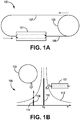
- FIG. 1A is a diagram illustrating a system 100 for injection locking a frequency of a laser (referred to interchangeably herein as a laser beam, optical beam, light beam, laser light, light, and the like) produced by a laser source 101 (such as a pump laser source) using a laser fed back from a resonator 103 (such as an SBS resonator, described in greater detail below).
- the system 100 includes a laser source 101.
- the laser source 101 may be capable of producing a laser at a particular frequency.
- the laser source 101 may be an electronic gain medium, a distributed feedback (DFB) semiconductor laser or other type of laser source.
- the laser sources described herein are capable of being fabricated within an integrated photonics chip, the laser source 101 may also include other laser sources that may be coupled to a separately located resonator 103 using fiber optics, optical waveguides, or other transmissive media.
- DFB distributed feedback
- the laser source 101 may be coupled through an optical path 105 to the resonator 103.
- the resonator 103 may any device through which light may resonate.
- the resonator 103 may be a fiber optic coil, a series of mirrors, and the like.
- the resonator 103 may provide an output laser at the resonance frequency from an output that is coupled through the optical path 107 to an input of the laser source 101.
- the output laser from the resonator 103 may be reflected back into the resonator 103 and through the laser source 101, where the output may again be reflected to the input of the laser source 101.
- the output laser provided by the resonator 103 to the laser source 101 through the optical path 107 may injection lock the laser produced by the laser source 101 to the resonance frequency of the resonator 103.
- injection locking occurs when a first oscillator, producing a laser at a first frequency (a launch frequency), is disturbed by a second laser at a second frequency, where the second frequency is close to the first frequency.
- the second laser may capture the first laser such that the frequencies of the first laser and the second laser become essentially identical.
- the output laser provided by the resonator 103 at the resonance frequency of the resonator 103 may capture the laser produced by the laser source 101 such that the laser produced by the laser source 101 is substantially equivalent to the resonance frequency of the resonator 103.
- FIG. 1B is a graph 106 illustrating the effects of injection locking within the system 100.
- the laser source 101 may produce a laser at frequency ( ⁇ 0 ) because the longitudinal mode 110 may have a higher gain than other produced modes.
- the laser source 101 may produce laser light having various frequency components along the gain curve 112 when the overall gain is equal to the loss.
- the resonance frequency 114 is within the frequencies having a substantive component within the gain curve 112
- a portion of the laser light emitted by the laser source 101 may resonate within the resonator 103.
- the resonator 103 may provide an output laser at the resonance frequency 114 back to the laser source 101.
- the laser produced by the laser source 101 may have higher overall gain near frequency 114 than the original laser frequency 110 due to the external feedback near frequency 114.
- the laser produced by the laser source 101 may begin to lase at a frequency close to the resonance frequency instead of the frequency 110.
- the output laser at the resonance frequency 114 may perturb the laser provided by the laser source 101 such that the launch frequency of the laser source 101 moves from the initial frequency 110 towards an injection locked frequency 108.
- the injection locked frequency 108 is substantially equal to the resonance frequency 114.
- the laser source 101 may provide a laser at a frequency that is locked to the resonance frequency 114 of the resonator 103.
- FIG. 2 is a block diagram of a system 200 for providing an SBS laser through the implementation of an injection-locked pump laser.
- the system 200 may include a pump laser source 201.
- the pump laser source 201 may be any laser source capable of providing a laser at a desired frequency.
- the pump laser source 201 may be an electrically pumped gain medium, a DFB laser, a DBR laser, a ring laser, or other type of laser-providing device.
- the pump laser source 201 may be coupled to an SBS filter 205, wherein the SBS filter 205 merely passes the received pump laser through to a transmission port of the SBS filter 205.
- the system 200 may include an SBS resonator 203.
- the SBS filter 205 may couple the received pump laser into the SBS resonator 203.
- a portion of the pump laser may propagate within the SBS resonator 203 at a particular resonance frequency of the SBS resonator 203.
- the pump laser may have light at a range of frequencies along a gain curve, where one or more of the resonance frequencies of the SBS resonator 203 are within the range of frequencies.
- the portions of the light of the pump laser at one of the resonance frequencies may propagate within the SBS resonator 203.
- Portions of the pump laser that are off resonance of the SBS resonator 203 may fail to propagate within the SBS resonator 203.
- the system 200 may include a pump laser path 207, where the pump laser path 207 routes an output of the SBS resonator 203 to an input of the pump laser source 201.
- the SBS resonator 203 may provide the portion of the pump laser that is at the resonance frequency of the SBS resonator 203 to the pump laser path 207.
- the pump laser path 207 may then couple the resonant portion of the pump laser to an input of the pump laser source 201.
- the pump laser path 207 may provide an optical path that couples an output from the SBS resonator 203 to the pump laser source 201.
- the optical path may include an optical fiber, waveguide, mirrors that reflect the light through free space, or other optical transmission medium.
- the SBS resonator 203 or the pump laser path 207 may reflect the pump laser through the original input of the SBS resonator 203.
- the back-reflected pump beam may then be provided back to the transmission port of the SBS filter 205, where the SBS filter 205 passes the back-reflected pump beam through to the pump laser source 201 as an external feedback, where the back-reflected pump beam may then cause the frequency of the pump laser provided by the pump laser source 201 to lock to the resonance frequency of the SBS resonator 203 in accordance with the effects of injection locking described above with respect to FIGS. 1A and IB.
- a SBS laser when the pump laser propagates in a particular direction within the SBS resonator 203, a SBS laser may propagate in an opposite direction within the SBS resonator 203 due to stimulated Brillouin scattering.
- the generated laser may be provided as an output from the SBS resonator 203 that is coupled into the SBS filter 205.
- the SBS filter 205 When the SBS filter 205 receives an SBS laser at the stimulated Brillouin scattering frequency, the SBS filter 205 may couple the SBS laser to a drop port of the SBS filter 205.
- the drop port of the SBS filter 205 may be coupled to an SBS output 209 of the system 200.
- the SBS output 209 may provide the SBS laser to other devices coupled to the system 200 or to other components within a larger system that encompasses the system 200.
- the different components within the system 200 may be fabricated within a single integrated photonics chip.
- the use of injection locking within the system 200 may allow the system 200 to lock the frequency of the pump laser produced by the pump laser source 201 to the resonance frequency of the SBS resonator 203 without implementing control loops having components that prevent the integration of the system 200 on a single integrated photonics chip.
- the various components of the system 200 may be implemented within a single integrated photonics chip, the components of the system 200 may also be comprised of separate components or groups of components that are coupled to one another through combinations of optical transmission media that may include fiber optics, optical waveguides, reflectors, and/or free space optical transmissions.
- FIG. 3 is a block diagram illustrating a system 300 for producing an SBS laser using an injection locked pump laser.
- the system 300 may be a detailed implementation of the system 200.
- the system 300 includes a pump laser source 301, an SBS filter 305, an SBS resonator 303, and a pump laser path 307 that function in a substantially similar manner to the pump laser source 201, the SBS filter 205, the SBS resonator 203, and the pump laser path 207 described above in FIG. 2 .
- the pump laser source 301 provides a pump laser substantially as described above in connection with the pump laser source 201 in FIG. 2 .
- the pump laser source 301 may be coupled to an input transmission port 305-a of an SBS filter 305.
- the SBS filter 305 may be an optical add/drop filter.
- the SBS filter 305 may include coupled optical waveguides having Bragg gratings formed therein. When light propagates through an input, the light may be coupled from one waveguide to the other based on the frequency of the light.
- the SBS filter 305 when the SBS filter 305 receives a laser through the input port 305-a at the frequency of the pump laser or near the resonance frequency of the SBS resonator 303, the SBS filter 305 may keep the pump laser within the same waveguide and couple the pump laser to the output port 305-b.
- the output port 305-b may be coupled to an input port 303-a of the SBS resonator 303.
- components of the pump laser at one or more of the resonance frequencies of the SBS resonator 303 may propagate within the SBS resonator 303.
- the SBS resonator 303 may provide components of the pump laser at one or more of the resonance frequencies of the SBS resonator 303 through the output port 303-b.
- the system 300 may include a pump laser filter 311 that is positioned between the SBS resonator 303 and the pump laser source 301.
- the output port 303-b of the SBS resonator 303 may be coupled to a pump laser filter 311 to attenuate undesired components of the pump laser that are at resonance frequencies of the SBS resonator 303 other than the resonance frequency of the SBS resonator 303 that incites the generation of the desired SBS laser.
- the frequency range of the light produced by the pump laser source 301 may span multiple resonance frequencies of the SBS resonator 303.
- the SBS resonator 303 may provide multiple optical beams associated with different resonance frequencies of the SBS resonator 303 through the output port 303-b.
- the pump laser filter 311 may be a bandpass filter that passes a single resonance frequency associated with the desired SBS laser frequency and attenuate the light at other resonance frequencies. Accordingly, the pump laser will lock to the desired resonance frequency.
- an SBS laser may be generated within the SBS resonator 303.
- the SBS laser may propagate in an opposite direction from the direction of propagation of the pump laser within the SBS resonator 303.
- the pump laser enters the SBS resonator 303 at port 303-a, may propagate in a clockwise direction within the SBS resonator 303, and is coupled out of the SBS resonator 303 at port 303-b.
- the SBS laser may be generated to propagate in the counter-clockwise direction within the SBS resonator 303 and coupled out of the SBS resonator 303 at port 303-a.
- clockwise and counter-clockwise are used herein to indicate a direction of propagation within the SBS resonator 303, the terms are used to indicate that the SBS laser and the pump laser propagate in opposite directions within the SBS resonator 303.
- the system 300 may couple the SBS laser into the SBS filter 305.
- the SBS filter 305 may pass optical beams at the frequency of the pump laser through the SBS filter 305 without coupling the pump laser from one waveguide to another.
- the SBS filter 305 may couple optical beams at the frequency of the SBS laser from one waveguide to another.
- the SBS filter 305 may receive the SBS laser on port 305-b and couple the SBS laser into another waveguide such that the SBS laser is coupled out of the SBS filter 305 at port 305-c.
- the port 305-c may then be coupled to an SBS laser output port 309 for the system 300.
- FIG. 4 is a block diagram illustrating an additional system 400 for producing an SBS laser using an injection locked pump laser.
- the system 400 is largely similar to the system 300.
- the pump laser source 401, the SBS filter 405, the SBS resonator 403, the SBS laser output port 409, and the pump laser path 407 function substantially as described above with respect to the pump laser source 301, SBS filter 305, SBS resonator 303, SBS laser output port 309, and pump laser path 307 in FIG. 3 .
- the system 400 is different from the system 300 in that the system 400 may not include a pump laser filter, such as the pump laser filter 311 in FIG. 3 .
- the pump laser source 301 may be able to produce laser light at a narrow range of frequencies.
- the range of frequencies may be narrow enough to include a single resonance frequency of the SBS resonator 403.
- the returned pump laser may be a narrow laser at a single resonance frequency.
- the system 400 may operate without a pump laser filter used to eliminate unwanted signals at different resonance frequencies of the SBS resonator 403 that are not associated with the creation of the SBS laser.
- FIG. 5 is a block diagram illustrating an additional system 500 for producing an SBS laser using an injection locked pump laser.
- the system 500 is similar to the system 300.
- the pump laser source 501, the SBS filter 505, the SBS resonator 503, the SBS laser output port 509, and the pump laser filter 511 function substantially as described above with respect to the pump laser source 301, the SBS filter 305, the SBS resonator 303, the SBS laser output port 309, and the pump laser filter 311 in FIG. 3 .
- the system 500 is different from the system 300 in that the mechanism for the pump laser path uses reflector 507-a to direct the pump laser to an input of the pump laser source 501.
- the pump laser when the pump laser beam enters the SBS resonator 503, the pump laser may be coupled out of the SBS resonator 503 at the output port 503-b.
- the output port 503-b may be coupled to a reflector 507-A.
- the reflector 507-a may be a partial reflector or full reflector. Additionally, the reflector 507-a may also be coupled to the output port 503-a of the SBS resonator 503 such that a portion of the pump laser is reflected back into the SBS resonator 503.
- the portion of the pump laser that is reflected back into the SBS resonator 503 may be coupled out of the SBS resonator 503 into the SBS filter 505, coupled through the pump laser filter 511, positioned between the SBS filter 505 and the pump laser source 501, and into the pump laser source 501, where the reflected pump laser locks the frequency of pump laser to a resonance frequency of the SBS resonator 503.
- FIG. 6 is a flowchart diagram of a method 600 for providing a self-injection locked SBS laser.
- the method 600 proceeds at 601, where a pump laser is produced at a pump laser source. Additionally, the method 600 proceeds at 603, where the pump laser is introduced into a first port of an SBS resonator. Further, the method 600 proceeds at 605, where a resonator output is coupled back into the pump laser source, wherein the output laser locks the pump laser to a resonance frequency of the SBS resonator. Moreover, the method 600 proceeds at 607, where an SBS laser is generated within the SBS resonator. For example, the Brillouin scattering of the pump laser within the SBS resonator may create an SBS laser that propagates in the opposite direction of the propagation direction of the pump laser.
Landscapes
- Physics & Mathematics (AREA)
- Electromagnetism (AREA)
- Optics & Photonics (AREA)
- Engineering & Computer Science (AREA)
- Plasma & Fusion (AREA)
- Condensed Matter Physics & Semiconductors (AREA)
- General Physics & Mathematics (AREA)
- Nonlinear Science (AREA)
- Lasers (AREA)
- Optical Modulation, Optical Deflection, Nonlinear Optics, Optical Demodulation, Optical Logic Elements (AREA)
Abstract
Description
- This invention was made with Government support under N66001-16-C-4017 awarded by SPAWAR Systems Center Pacific. The Government has certain rights in the invention.
- Stimulated Brillouin scattering (SBS) lasers may be used in a wide range of sensing and metrology applications. For example, SBS lasers may provide narrow linewidth optical emissions within small integrated photonics packages. Typically, to stimulate the Brillouin scattering, an external pump laser source (a laser source outside of an integrated photonics package) may provide a pump laser to a Brillouin cavity. To align the frequency of the pump laser with the resonance frequency of the Brillouin cavity, systems may include feedback loops, such as Pound-Drever-Hall (PDH) loops. The PDH loops typically include a phase modulator, detector, mixer, and proportional-integral-derivative (PID) controller. Frequently, at least some of the components of the PDH loop are fabricated outside of the integrated photonics package.
- Systems and methods for a self-injection locked stimulated Brillouin scattering laser are provided herein. In certain embodiments, a system includes a pump laser source that provides a pump laser. The system further includes a stimulated Brillouin scattering (SBS) resonator that receives the pump laser through a first port, wherein the SBS resonator scatters a portion of the pump laser to provide an SBS laser through the first port, and wherein a frequency shift of Brillouin scattering within the SBS resonator is an integer multiple of a free-spectral range for the SBS resonator. Also, the system includes a filter that receives the pump laser on a first filter port and the SBS laser on a second filter port, wherein the pump laser is output through the second filter port and the SBS laser is output through a drop port. Additionally, the system includes a pump laser path that couples the output pump laser from the SBS resonator into the pump laser source, wherein a frequency of the pump laser becomes locked to a frequency of the output pump laser at a resonance frequency of the SBS resonator.
- Understanding that the drawings depict only some embodiments and are not therefore to be considered limiting in scope, the exemplary embodiments will be described with additional specificity and detail using the accompanying drawings, in which:
-
FIG. 1A is a diagram illustrating a system for injection locking a frequency of a laser using a resonator according to an aspect of the present disclosure; -
FIG. 1B is a graph illustrating the effects of injection locking a frequency of a laser using a resonator according to an aspect of the present disclosure; -
FIG. 2 is a block diagram illustrating an exemplary system for providing a self-injection locked stimulated Brillouin scattering laser according to an aspect of the present disclosure; -
FIG. 3 is a block diagram illustrating an exemplary system for providing a self-injection locked stimulated Brillouin scattering laser according to an aspect of the present disclosure; -
FIG. 4 is a block diagram illustrating an exemplary system for providing a self-injection locked stimulated Brillouin scattering laser according to an aspect of the present disclosure; -
FIG. 5 is a block diagram illustrating an exemplary system for providing a self-injection locked stimulated Brillouin scattering laser according to an aspect of the present disclosure; and -
FIG. 6 is a flow chart diagram illustrating an exemplary method for providing a self-injection locked stimulated Brillouin scattering laser according to an aspect of the present disclosure. - In accordance with common practice, the various described features are not drawn to scale but are drawn to emphasize specific features relevant to the example embodiments.
- In the following detailed description, reference is made to the accompanying drawings that form a part hereof, and in which is shown by way of illustration specific illustrative embodiments. However, it is to be understood that other embodiments may be utilized and that logical, mechanical, and electrical changes may be made.
- Embodiments described herein provide for a self-injection locked stimulated Brillouin scattering (SBS) laser. In particular, an electrically pumped gain medium may be placed in the same external optical cavity as the associated Brillouin gain resonator. Using the self-injection locking effect, the resonance frequency of the Brillouin gain resonator may control the frequency of the emitted pump laser beam generated by the electrically pumped gain medium. Thus, the optical pump beam for stimulating the Brillouin laser may automatically align itself with the appropriate resonance frequency of the Brillouin resonator.
- In embodiments using the self-injection locked SBS laser, the components of the SBS laser may be fabricated as a single integrated photonics device. For instance, as the SBS resonator automatically controls the frequency of the emitted pump laser to be at a resonance frequency of the SBS resonator, the self-injection locked SBS laser may be fabricated without control loops (such as the Pound-Drever-Hall (PDH) loop). By eliminating bulky and complex control loops, the SBS laser may be implemented on a single photonics chip. As the SBS laser can be made on a single chip, the SBS laser may be cheaper and less complex to manufacture.
-
FIG. 1A is a diagram illustrating asystem 100 for injection locking a frequency of a laser (referred to interchangeably herein as a laser beam, optical beam, light beam, laser light, light, and the like) produced by a laser source 101 (such as a pump laser source) using a laser fed back from a resonator 103 (such as an SBS resonator, described in greater detail below). As shown, thesystem 100 includes alaser source 101. Thelaser source 101 may be capable of producing a laser at a particular frequency. For example, thelaser source 101 may be an electronic gain medium, a distributed feedback (DFB) semiconductor laser or other type of laser source. While the laser sources described herein are capable of being fabricated within an integrated photonics chip, thelaser source 101 may also include other laser sources that may be coupled to a separately locatedresonator 103 using fiber optics, optical waveguides, or other transmissive media. - In some embodiments, the
laser source 101 may be coupled through anoptical path 105 to theresonator 103. As used herein, theresonator 103 may any device through which light may resonate. For example, theresonator 103 may be a fiber optic coil, a series of mirrors, and the like. When theresonator 103 receives the laser from thelaser source 101, a portion of the received laser may resonate within theresonator 103 at a resonance frequency, where the resonance frequency is dependent upon the length of the fiber within theresonator 103. Further, theresonator 103 may provide an output laser at the resonance frequency from an output that is coupled through theoptical path 107 to an input of thelaser source 101. Alternatively, the output laser from theresonator 103 may be reflected back into theresonator 103 and through thelaser source 101, where the output may again be reflected to the input of thelaser source 101. - In certain embodiments, the output laser provided by the
resonator 103 to thelaser source 101 through theoptical path 107 may injection lock the laser produced by thelaser source 101 to the resonance frequency of theresonator 103. As known to one having skill in the art, injection locking occurs when a first oscillator, producing a laser at a first frequency (a launch frequency), is disturbed by a second laser at a second frequency, where the second frequency is close to the first frequency. When the first and second frequencies are close enough to one another, the second laser may capture the first laser such that the frequencies of the first laser and the second laser become essentially identical. With regards to thesystem 100, the output laser provided by theresonator 103 at the resonance frequency of theresonator 103 may capture the laser produced by thelaser source 101 such that the laser produced by thelaser source 101 is substantially equivalent to the resonance frequency of theresonator 103. -
FIG. 1B is agraph 106 illustrating the effects of injection locking within thesystem 100. Without external feedback, thelaser source 101 may produce a laser at frequency (ω0) because thelongitudinal mode 110 may have a higher gain than other produced modes. As shown, thelaser source 101 may produce laser light having various frequency components along thegain curve 112 when the overall gain is equal to the loss. As theresonance frequency 114 is within the frequencies having a substantive component within thegain curve 112, a portion of the laser light emitted by thelaser source 101 may resonate within theresonator 103. Thus, theresonator 103 may provide an output laser at theresonance frequency 114 back to thelaser source 101. Accordingly, the laser produced by thelaser source 101 may have higher overall gain nearfrequency 114 than theoriginal laser frequency 110 due to the external feedback nearfrequency 114. Thus, the laser produced by thelaser source 101 may begin to lase at a frequency close to the resonance frequency instead of thefrequency 110. In certain embodiments, the output laser at theresonance frequency 114 may perturb the laser provided by thelaser source 101 such that the launch frequency of thelaser source 101 moves from theinitial frequency 110 towards an injection lockedfrequency 108. As shown, the injection lockedfrequency 108 is substantially equal to theresonance frequency 114. Thus, thelaser source 101 may provide a laser at a frequency that is locked to theresonance frequency 114 of theresonator 103. -
FIG. 2 is a block diagram of asystem 200 for providing an SBS laser through the implementation of an injection-locked pump laser. As shown, thesystem 200 may include apump laser source 201. Thepump laser source 201 may be any laser source capable of providing a laser at a desired frequency. For example, thepump laser source 201 may be an electrically pumped gain medium, a DFB laser, a DBR laser, a ring laser, or other type of laser-providing device. Thepump laser source 201 may be coupled to anSBS filter 205, wherein theSBS filter 205 merely passes the received pump laser through to a transmission port of theSBS filter 205. - In certain embodiments, the
system 200 may include anSBS resonator 203. In some implementations, after receiving the pump laser from thepump laser source 201, theSBS filter 205 may couple the received pump laser into theSBS resonator 203. A portion of the pump laser may propagate within theSBS resonator 203 at a particular resonance frequency of theSBS resonator 203. For example, as discussed above with respect toFIGS. 1A-1B , the pump laser may have light at a range of frequencies along a gain curve, where one or more of the resonance frequencies of theSBS resonator 203 are within the range of frequencies. The portions of the light of the pump laser at one of the resonance frequencies may propagate within theSBS resonator 203. Portions of the pump laser that are off resonance of theSBS resonator 203 may fail to propagate within theSBS resonator 203. - In some embodiments, the
system 200 may include apump laser path 207, where thepump laser path 207 routes an output of theSBS resonator 203 to an input of thepump laser source 201. For example, theSBS resonator 203 may provide the portion of the pump laser that is at the resonance frequency of theSBS resonator 203 to thepump laser path 207. Thepump laser path 207 may then couple the resonant portion of the pump laser to an input of thepump laser source 201. As the resonant frequency of the pump laser is near the resonant frequency of theSBS resonator 203 external feedback provided by theSBS resonator 203 may cause the frequency of the pump laser to lock to the resonance frequency of theSBS resonator 203 due to effects of injection locking as described above with respect toFIGs. 1A and IB. - In further embodiments, to couple the output of the
SBS resonator 203 to thepump laser source 201, thepump laser path 207 may provide an optical path that couples an output from theSBS resonator 203 to thepump laser source 201. The optical path may include an optical fiber, waveguide, mirrors that reflect the light through free space, or other optical transmission medium. Alternatively, theSBS resonator 203 or thepump laser path 207 may reflect the pump laser through the original input of theSBS resonator 203. The back-reflected pump beam may then be provided back to the transmission port of theSBS filter 205, where theSBS filter 205 passes the back-reflected pump beam through to thepump laser source 201 as an external feedback, where the back-reflected pump beam may then cause the frequency of the pump laser provided by thepump laser source 201 to lock to the resonance frequency of theSBS resonator 203 in accordance with the effects of injection locking described above with respect toFIGS. 1A and IB. - In certain embodiments, when the pump laser propagates in a particular direction within the
SBS resonator 203, a SBS laser may propagate in an opposite direction within theSBS resonator 203 due to stimulated Brillouin scattering. The generated laser may be provided as an output from theSBS resonator 203 that is coupled into theSBS filter 205. When theSBS filter 205 receives an SBS laser at the stimulated Brillouin scattering frequency, theSBS filter 205 may couple the SBS laser to a drop port of theSBS filter 205. The drop port of theSBS filter 205 may be coupled to anSBS output 209 of thesystem 200. TheSBS output 209 may provide the SBS laser to other devices coupled to thesystem 200 or to other components within a larger system that encompasses thesystem 200. - As described above, by using injection locking of the
pump laser source 201, the different components within thesystem 200 may be fabricated within a single integrated photonics chip. In particular, the use of injection locking within thesystem 200 may allow thesystem 200 to lock the frequency of the pump laser produced by thepump laser source 201 to the resonance frequency of theSBS resonator 203 without implementing control loops having components that prevent the integration of thesystem 200 on a single integrated photonics chip. While the various components of thesystem 200 may be implemented within a single integrated photonics chip, the components of thesystem 200 may also be comprised of separate components or groups of components that are coupled to one another through combinations of optical transmission media that may include fiber optics, optical waveguides, reflectors, and/or free space optical transmissions. -
FIG. 3 is a block diagram illustrating asystem 300 for producing an SBS laser using an injection locked pump laser. In particular, thesystem 300 may be a detailed implementation of thesystem 200. For example, thesystem 300 includes apump laser source 301, anSBS filter 305, anSBS resonator 303, and apump laser path 307 that function in a substantially similar manner to thepump laser source 201, theSBS filter 205, theSBS resonator 203, and thepump laser path 207 described above inFIG. 2 . - In certain embodiments, the
pump laser source 301 provides a pump laser substantially as described above in connection with thepump laser source 201 inFIG. 2 . Thepump laser source 301 may be coupled to an input transmission port 305-a of anSBS filter 305. As illustrated, theSBS filter 305 may be an optical add/drop filter. For example, theSBS filter 305 may include coupled optical waveguides having Bragg gratings formed therein. When light propagates through an input, the light may be coupled from one waveguide to the other based on the frequency of the light. With regards to the pump laser, when theSBS filter 305 receives a laser through the input port 305-a at the frequency of the pump laser or near the resonance frequency of theSBS resonator 303, theSBS filter 305 may keep the pump laser within the same waveguide and couple the pump laser to the output port 305-b. - In some embodiments, the output port 305-b may be coupled to an input port 303-a of the
SBS resonator 303. As described above inFIG. 2 , components of the pump laser at one or more of the resonance frequencies of theSBS resonator 303 may propagate within theSBS resonator 303. Accordingly, theSBS resonator 303 may provide components of the pump laser at one or more of the resonance frequencies of theSBS resonator 303 through the output port 303-b. - In certain embodiments, the
system 300 may include apump laser filter 311 that is positioned between theSBS resonator 303 and thepump laser source 301. In particular, the output port 303-b of theSBS resonator 303 may be coupled to apump laser filter 311 to attenuate undesired components of the pump laser that are at resonance frequencies of theSBS resonator 303 other than the resonance frequency of theSBS resonator 303 that incites the generation of the desired SBS laser. For example, the frequency range of the light produced by thepump laser source 301 may span multiple resonance frequencies of theSBS resonator 303. Accordingly, theSBS resonator 303 may provide multiple optical beams associated with different resonance frequencies of theSBS resonator 303 through the output port 303-b. To ensure that the pump laser produced by thepump laser source 301 locks to the correct resonance frequency, thepump laser filter 311 may be a bandpass filter that passes a single resonance frequency associated with the desired SBS laser frequency and attenuate the light at other resonance frequencies. Accordingly, the pump laser will lock to the desired resonance frequency. - As described above, when the pump laser propagates within the
SBS resonator 303, an SBS laser may be generated within theSBS resonator 303. The SBS laser may propagate in an opposite direction from the direction of propagation of the pump laser within theSBS resonator 303. For example, the pump laser enters theSBS resonator 303 at port 303-a, may propagate in a clockwise direction within theSBS resonator 303, and is coupled out of theSBS resonator 303 at port 303-b. Conversely, the SBS laser may be generated to propagate in the counter-clockwise direction within theSBS resonator 303 and coupled out of theSBS resonator 303 at port 303-a. While the terms "clockwise" and "counter-clockwise" are used herein to indicate a direction of propagation within theSBS resonator 303, the terms are used to indicate that the SBS laser and the pump laser propagate in opposite directions within theSBS resonator 303. - In certain embodiments, when the SBS laser is coupled out of the port 303-a from the
SBS resonator 303, thesystem 300 may couple the SBS laser into theSBS filter 305. As described above, in relation to the pump laser, theSBS filter 305 may pass optical beams at the frequency of the pump laser through theSBS filter 305 without coupling the pump laser from one waveguide to another. However, theSBS filter 305 may couple optical beams at the frequency of the SBS laser from one waveguide to another. For example, theSBS filter 305 may receive the SBS laser on port 305-b and couple the SBS laser into another waveguide such that the SBS laser is coupled out of theSBS filter 305 at port 305-c. The port 305-c may then be coupled to an SBSlaser output port 309 for thesystem 300. -
FIG. 4 is a block diagram illustrating an additional system 400 for producing an SBS laser using an injection locked pump laser. The system 400 is largely similar to thesystem 300. For example, thepump laser source 401, theSBS filter 405, theSBS resonator 403, the SBSlaser output port 409, and thepump laser path 407 function substantially as described above with respect to thepump laser source 301,SBS filter 305,SBS resonator 303, SBSlaser output port 309, and pumplaser path 307 inFIG. 3 . However, the system 400 is different from thesystem 300 in that the system 400 may not include a pump laser filter, such as thepump laser filter 311 inFIG. 3 . - In some embodiments, the
pump laser source 301 may be able to produce laser light at a narrow range of frequencies. In particular, the range of frequencies may be narrow enough to include a single resonance frequency of theSBS resonator 403. When the range of frequencies includes a single resonance frequency, when the pump laser is returned along thepump laser path 407 from theSBS resonator 403, the returned pump laser may be a narrow laser at a single resonance frequency. As the returned pump laser includes a single resonance frequency, the system 400 may operate without a pump laser filter used to eliminate unwanted signals at different resonance frequencies of theSBS resonator 403 that are not associated with the creation of the SBS laser. -
FIG. 5 is a block diagram illustrating an additional system 500 for producing an SBS laser using an injection locked pump laser. The system 500 is similar to thesystem 300. For example, thepump laser source 501, theSBS filter 505, theSBS resonator 503, the SBSlaser output port 509, and thepump laser filter 511 function substantially as described above with respect to thepump laser source 301, theSBS filter 305, theSBS resonator 303, the SBSlaser output port 309, and thepump laser filter 311 inFIG. 3 . However, the system 500 is different from thesystem 300 in that the mechanism for the pump laser path uses reflector 507-a to direct the pump laser to an input of thepump laser source 501. - In certain embodiments, when the pump laser beam enters the
SBS resonator 503, the pump laser may be coupled out of theSBS resonator 503 at the output port 503-b. The output port 503-b may be coupled to a reflector 507-A. The reflector 507-a may be a partial reflector or full reflector. Additionally, the reflector 507-a may also be coupled to the output port 503-a of theSBS resonator 503 such that a portion of the pump laser is reflected back into theSBS resonator 503. The portion of the pump laser that is reflected back into theSBS resonator 503 may be coupled out of theSBS resonator 503 into theSBS filter 505, coupled through thepump laser filter 511, positioned between theSBS filter 505 and thepump laser source 501, and into thepump laser source 501, where the reflected pump laser locks the frequency of pump laser to a resonance frequency of theSBS resonator 503. -
FIG. 6 is a flowchart diagram of amethod 600 for providing a self-injection locked SBS laser. As shown, themethod 600 proceeds at 601, where a pump laser is produced at a pump laser source. Additionally, themethod 600 proceeds at 603, where the pump laser is introduced into a first port of an SBS resonator. Further, themethod 600 proceeds at 605, where a resonator output is coupled back into the pump laser source, wherein the output laser locks the pump laser to a resonance frequency of the SBS resonator. Moreover, themethod 600 proceeds at 607, where an SBS laser is generated within the SBS resonator. For example, the Brillouin scattering of the pump laser within the SBS resonator may create an SBS laser that propagates in the opposite direction of the propagation direction of the pump laser. -
- Example 1 includes a system comprising: a pump laser source that provides a pump laser; a stimulated Brillouin scattering (SBS) resonator that receives the pump laser through a first port, wherein the SBS resonator scatters a portion of the pump laser to provide an SBS laser through the first port, and wherein a frequency shift of Brillouin scattering within the SBS resonator is an integer multiple of a free-spectral range for the SBS resonator; a filter that receives the pump laser on a first filter port and the SBS laser on a second filter port, wherein the pump laser is output through the second filter port and the SBS laser is output through a drop port; and a pump laser path that couples the output pump laser from the SBS resonator into the pump laser source, wherein a frequency of the pump laser becomes locked to a frequency of the output pump laser at a resonance frequency of the SBS resonator.
- Example 2 includes the system of Example 1, wherein the pump laser path comprises an optical path that couples a transmission port of the SBS resonator to the pump laser source.
- Example 3 includes the system of Example 2, further comprising a pump laser filter coupled in the optical path between the SBS resonator and the pump laser source.
- Example 4 includes the system of any of Examples 1-3, wherein the pump laser path comprises: a mirror that reflects the output pump laser back into a transmission port of the SBS resonator, wherein the output pump laser propagates from the first port of the SBS resonator, through the filter and the pump laser source; and a second mirror that reflects the output pump laser back into the pump laser source after the output pump laser has passed through the pump laser source.
- Example 5 includes the system of Example 4, further comprising a pump laser filter positioned between the filter and the pump laser source, wherein the pump laser filter attenuates components of the output pump laser at undesired resonance frequencies of the SBS resonator.
- Example 6 includes the system of any of Examples 1-5, wherein the pump laser source provides a range of frequencies that includes a single resonance frequency of the SBS resonator.
- Example 7 includes the system of any of Examples 1-6, wherein the pump laser source, the filter, and the SBS resonator are fabricated on an integrated photonics chip.
- Example 8 includes a method comprising: producing a pump laser at a pump laser source; introducing the pump laser into a first port of a stimulated Brillouin scattering (SBS) resonator; coupling an output laser into the pump laser source, wherein the output laser is provided from a second port of the SBS resonator at a resonance frequency of the SBS resonator and the output laser locks the pump laser to the resonance frequency of the SBS resonator; and generating an SBS laser within the SBS resonator.
- Example 9 includes the method of Example 8, wherein coupling the output laser into the input of the pump laser source comprises coupling an optical transmission medium between the SBS resonator and the input of the pump laser source.
- Example 10 includes the method of Example 9, further comprising filtering the pump laser source between the SBS resonator and the pump laser source to attenuate components of the output laser at undesired resonance frequencies.
- Example 11 includes the method of any of Examples 8-10, wherein coupling the output laser into the input of the pump laser source comprises: reflecting the output laser back into the second port of the SBS resonator, wherein the output laser propagates from the first port of the SBS resonator and through the pump laser source; and reflecting the output pump laser back into the pump laser source after the output pump laser has passed through the pump laser source.
- Example 12 includes the method of Example 11, further comprising filtering the pump laser source between the SBS resonator and the pump laser source to attenuate components of the output laser at undesired resonance frequencies of the SBS resonator.
- Example 13 includes the method of any of Examples 8-12, wherein producing the pump laser comprises producing a laser having a frequency range that includes a single resonance frequency of the SBS resonator.
- Example 14 includes the method of any of Examples 8-13, further comprising forming the pump laser source and the SBS resonator on an integrated photonics chip.
- Example 15 includes the method of Example 14, further comprising coupling the SBS laser off of the integrated photonics chip.
- Example 16 includes the method of Example 15, wherein coupling the SBS laser off of the integrated photonics chip comprises passing the SBS laser through an SBS filter that couples the SBS laser off of the integrated photonics chip through a drop port.
- Example 17 includes a system comprising: a stimulated Brillouin scattering (SBS) resonator that provides an SBS laser through a first port of the SBS resonator in response to light propagating within the resonator; a pump laser source that provides a pump laser that is coupled into the SBS resonator through the first port and an output pump laser is coupled out of the SBS resonator through a second port of the SBS resonator; and a pump laser path that couples the output pump laser from the second port of the SBS resonator into an input of the pump laser source, wherein a frequency of the pump laser locks to a resonance frequency of the SBS resonator.
- Example 18 includes the system of Example 17, further comprising a filter that receives the pump laser on a first filter port and the SBS laser on a second filter port, wherein the pump laser is output through the second filter port and the SBS laser is output through a drop port.
- Example 19 includes the system of any of Examples 17-18, wherein the pump laser path comprises an optical path that couples the second port of the SBS resonator to the input of the pump laser source.
- Example 20 includes the system of any of Examples 17-19, wherein the pump laser path comprises: a mirror that reflects the output pump laser back into the second port of the SBS resonator, wherein the output pump laser propagates from the first port of the SBS resonator and through the pump laser source; and a second mirror that reflects the output pump laser back into the pump laser source after the output pump laser has passed through the pump laser source.
- Although specific embodiments have been illustrated and described herein, it will be appreciated by those of ordinary skill in the art that any arrangement, which is calculated to achieve the same purpose, may be substituted for the specific embodiments shown. Therefore, it is manifestly intended that this invention be limited only by the claims and the equivalents thereof.
Claims (10)
- A system comprising:a pump laser source (301) that provides a pump laser;a stimulated Brillouin scattering (SBS) resonator (303) that receives the pump laser through a first port (303-a), wherein the SBS resonator (303) scatters a portion of the pump laser to provide an SBS laser through the first port (303-a), and wherein a frequency shift of Brillouin scattering within the SBS resonator (303) is an integer multiple of a free-spectral range for the SBS resonator (303);a filter (305) that receives the pump laser on a first filter port (305-a) and the SBS laser on a second filter port (305-b), wherein the pump laser is output through the second filter port (305-b) and the SBS laser is output through a drop port (305-c); anda pump laser path (307) that couples the output pump laser from the SBS resonator (303) into the pump laser source (301), wherein a frequency of the pump laser becomes locked to a frequency of the output pump laser at a resonance frequency of the SBS resonator (303).
- The system of claim 1, wherein the pump laser path (307) comprises an optical path that couples a transmission port (303-b) of the SBS resonator (303) to the pump laser source (301), further comprising:
a pump laser filter (311) coupled in the optical path between the SBS resonator (303) and the pump laser source (301). - The system of claim 1, wherein the pump laser path (307) comprises:a mirror that reflects the output pump laser back into a transmission port (303-b) of the SBS resonator (303), wherein the output pump laser propagates from the first port (303-a) of the SBS resonator (303), through the filter (305) and the pump laser source (301); anda second mirror that reflects the output pump laser back into the pump laser source (301) after the output pump laser has passed through the pump laser source (301).a pump laser filter (311) positioned between the filter and the pump laser source (301), wherein the pump laser filter (311) attenuates components of the output pump laser at undesired resonance frequencies of the SBS resonator (303).
- The system of claim 1, wherein the pump laser source (301) provides a range of frequencies that includes a single resonance frequency of the SBS resonator (303).
- The system of claim 1, wherein the pump laser source (301), the filter (305), and the SBS resonator (303) are fabricated on an integrated photonics chip.
- A method comprising:producing a pump laser at a pump laser source (301);introducing the pump laser into a first port (303-a) of a stimulated Brillouin scattering (SBS) resonator (303);coupling an output laser into the pump laser source (301), wherein the output laser is provided from a second port of the SBS resonator (303) at a resonance frequency of the SBS resonator (303) and the output laser locks the pump laser to the resonance frequency of the SBS resonator (303); andgenerating an SBS laser within the SBS resonator (303).
- The method of claim 6, wherein coupling the output laser into the input of the pump laser source (301) comprises:coupling an optical transmission medium between the SBS resonator (303) and the input of the pump laser source (301); andfiltering the pump laser source (301) between the SBS resonator (303) and the pump laser source (301) to attenuate components of the output laser at undesired resonance frequencies.
- The method of claim 6, wherein coupling the output laser into the input of the pump laser source (301) comprises:reflecting the output laser back into the second port of the SBS resonator (303), wherein the output laser propagates from the first port (303-a) of the SBS resonator (303) and through the pump laser source (301);reflecting the output pump laser back into the pump laser source (301) after the output pump laser has passed through the pump laser source (301); andfiltering the pump laser source (301) between the SBS resonator (303) and the pump laser source (301) to attenuate components of the output laser at undesired resonance frequencies of the SBS resonator (303).
- The method of claim 6, wherein producing the pump laser comprises producing a laser having a frequency range that includes a single resonance frequency of the SBS resonator (303).
- The method of claim 6, further comprising:forming the pump laser source (301) and the SBS resonator (303) on an integrated photonics chip.coupling the SBS laser off of the integrated photonics chip by passing the SBS laser through an SBS filter (305) that couples the SBS laser off of the integrated photonics chip through a drop port (305-c).
Applications Claiming Priority (1)
| Application Number | Priority Date | Filing Date | Title |
|---|---|---|---|
| US16/892,016 US11362480B2 (en) | 2020-06-03 | 2020-06-03 | Self-injection locked stimulated Brillouin scattering laser |
Publications (2)
| Publication Number | Publication Date |
|---|---|
| EP3920346A1 true EP3920346A1 (en) | 2021-12-08 |
| EP3920346B1 EP3920346B1 (en) | 2025-04-30 |
Family
ID=75223086
Family Applications (1)
| Application Number | Title | Priority Date | Filing Date |
|---|---|---|---|
| EP21164725.0A Active EP3920346B1 (en) | 2020-06-03 | 2021-03-24 | Self-injection locked stimulated brillouin scattering laser |
Country Status (2)
| Country | Link |
|---|---|
| US (1) | US11362480B2 (en) |
| EP (1) | EP3920346B1 (en) |
Families Citing this family (3)
| Publication number | Priority date | Publication date | Assignee | Title |
|---|---|---|---|---|
| US11460372B2 (en) * | 2020-09-03 | 2022-10-04 | Ciena Corporation | Characterizing integrated photonics devices |
| US12218483B2 (en) | 2022-01-21 | 2025-02-04 | Honeywell International Inc. | Tunable RF synthesizer based on offset optical frequency combs |
| US20250323470A1 (en) * | 2024-04-11 | 2025-10-16 | Honeywell International Inc. | Widely tunable brillouin laser based on vernier filter external cavity |
Citations (1)
| Publication number | Priority date | Publication date | Assignee | Title |
|---|---|---|---|---|
| DE102004003750A1 (en) * | 2004-01-23 | 2005-08-11 | Raab, Volker, Dr. | Coupled optical resonators |
Family Cites Families (6)
| Publication number | Priority date | Publication date | Assignee | Title |
|---|---|---|---|---|
| US5272717A (en) | 1992-01-17 | 1993-12-21 | Hughes Aircraft Company | Single focus backward Raman laser |
| KR970005166B1 (en) | 1993-04-24 | 1997-04-12 | 국방과학연구소 | Equipment and method oscillating raman laser using stimulated raman scattering |
| US9197032B2 (en) | 2014-04-02 | 2015-11-24 | Honeywell International Inc. | Systems and methods for stabilized stimulated brillouin scattering lasers with ultra-low phase noise |
| CN105024273A (en) | 2014-04-24 | 2015-11-04 | 中国科学院大连化学物理研究所 | Intra-cavity laser shaping realization method by means of stimulated Brillouin scattering and device thereof |
| CN205193401U (en) | 2015-12-10 | 2016-04-27 | 华北电力大学(保定) | Pulsed laser efficient stimulated brillouin scattering device |
| US10312658B2 (en) * | 2017-06-22 | 2019-06-04 | Honeywell International Inc. | Brillouin gain spectral position control of claddings for tuning acousto-optic waveguides |
-
2020
- 2020-06-03 US US16/892,016 patent/US11362480B2/en active Active
-
2021
- 2021-03-24 EP EP21164725.0A patent/EP3920346B1/en active Active
Patent Citations (1)
| Publication number | Priority date | Publication date | Assignee | Title |
|---|---|---|---|---|
| DE102004003750A1 (en) * | 2004-01-23 | 2005-08-11 | Raab, Volker, Dr. | Coupled optical resonators |
Non-Patent Citations (2)
| Title |
|---|
| SARAT GUNDAVARAPU ET AL: "Sub-Hz Linewidth Photonic-Integrated Brillouin Laser", ARXIV.ORG, CORNELL UNIVERSITY LIBRARY, 201 OLIN LIBRARY CORNELL UNIVERSITY ITHACA, NY 14853, 27 February 2018 (2018-02-27), XP081406629, DOI: 10.1038/S41566-018-0313-2 * |
| SPIRIN V V ET AL: "Single-mode Brillouin fiber laser passively stabilized at resonance frequency with self-injection locked pump laser", LASER PHYSICS LETTERS, vol. 9, no. 5, 1 May 2012 (2012-05-01), Germany, pages 377 - 380, XP055843464, ISSN: 1612-2011, DOI: 10.7452/lapl.201110138 * |
Also Published As
| Publication number | Publication date |
|---|---|
| US20210384695A1 (en) | 2021-12-09 |
| EP3920346B1 (en) | 2025-04-30 |
| US11362480B2 (en) | 2022-06-14 |
Similar Documents
| Publication | Publication Date | Title |
|---|---|---|
| EP3920346B1 (en) | Self-injection locked stimulated brillouin scattering laser | |
| JP6415799B2 (en) | Narrowband reflector for reducing stimulated Brillouin scattering in optical cavities | |
| CA2177733C (en) | Coupled multiple output fiber laser | |
| US10522968B2 (en) | Narrow linewidth multi-wavelength light sources | |
| JP5290737B2 (en) | Optical-microwave oscillator and pulse generator | |
| EP2927636B1 (en) | Systems and methods for stabilized stimulated brillouin scattering lasers with ultra-low phase noise | |
| US20090074014A1 (en) | Mode selection for single frequency fiber laser | |
| JP2000036630A (en) | Optical signal surface | |
| US5384799A (en) | Frequency stabilized laser with electronic tunable external cavity | |
| CN112018590B (en) | Multiwavelength Non-Atomic Resonant Faraday Semiconductor Laser | |
| CN1145828C (en) | Single-mode fiber ring laser and method of producing single-mode laser output therefrom | |
| Takata et al. | Current-feedback-stabilized laser system for quantum simulation experiments using Yb clock transition at 578 nm | |
| JP6941121B2 (en) | Spectral narrowing module, narrowing spectral line device, and methods for doing so | |
| CN116470961B (en) | Device and method for generating periodic oscillation millimeter wave signal by mutual injection | |
| KR100559057B1 (en) | Millimeter wave oscillator using optical fiber diffraction grating | |
| JP2006515110A (en) | Return reflected light insensitive electro-optic interface and method for coupling it to a waveguide | |
| US20030114117A1 (en) | Tunable RF signal generation | |
| JPS6255983A (en) | External light feedback semiconductor laser using optical fiber | |
| US20250323470A1 (en) | Widely tunable brillouin laser based on vernier filter external cavity | |
| US12218483B2 (en) | Tunable RF synthesizer based on offset optical frequency combs | |
| JP2008263362A (en) | Gas-cell type atomic oscillator | |
| JPH05299758A (en) | Frequency-stabilized ring laser | |
| CN121887306A (en) | A full-band noise microwave source system and a microwave signal generation method | |
| AU2006256749A1 (en) | Very low-noise semi-conductor laser | |
| CN118693611A (en) | Semiconductor laser and laser radar |
Legal Events
| Date | Code | Title | Description |
|---|---|---|---|
| PUAI | Public reference made under article 153(3) epc to a published international application that has entered the european phase |
Free format text: ORIGINAL CODE: 0009012 |
|
| STAA | Information on the status of an ep patent application or granted ep patent |
Free format text: STATUS: THE APPLICATION HAS BEEN PUBLISHED |
|
| AK | Designated contracting states |
Kind code of ref document: A1 Designated state(s): AL AT BE BG CH CY CZ DE DK EE ES FI FR GB GR HR HU IE IS IT LI LT LU LV MC MK MT NL NO PL PT RO RS SE SI SK SM TR |
|
| B565 | Issuance of search results under rule 164(2) epc |
Effective date: 20211001 |
|
| STAA | Information on the status of an ep patent application or granted ep patent |
Free format text: STATUS: REQUEST FOR EXAMINATION WAS MADE |
|
| 17P | Request for examination filed |
Effective date: 20211207 |
|
| RBV | Designated contracting states (corrected) |
Designated state(s): AL AT BE BG CH CY CZ DE DK EE ES FI FR GB GR HR HU IE IS IT LI LT LU LV MC MK MT NL NO PL PT RO RS SE SI SK SM TR |
|
| STAA | Information on the status of an ep patent application or granted ep patent |
Free format text: STATUS: EXAMINATION IS IN PROGRESS |
|
| 17Q | First examination report despatched |
Effective date: 20220304 |
|
| P01 | Opt-out of the competence of the unified patent court (upc) registered |
Effective date: 20230421 |
|
| RIC1 | Information provided on ipc code assigned before grant |
Ipc: H01S 5/14 20060101ALI20241023BHEP Ipc: H01S 5/12 20210101ALI20241023BHEP Ipc: H01S 5/065 20060101ALI20241023BHEP Ipc: H01S 3/30 20060101ALI20241023BHEP Ipc: H01S 3/0941 20060101ALI20241023BHEP Ipc: H01S 3/083 20060101ALI20241023BHEP Ipc: H01S 3/082 20060101ALI20241023BHEP Ipc: H01S 3/08022 20230101ALI20241023BHEP Ipc: H01S 3/10 20060101AFI20241023BHEP |
|
| GRAP | Despatch of communication of intention to grant a patent |
Free format text: ORIGINAL CODE: EPIDOSNIGR1 |
|
| STAA | Information on the status of an ep patent application or granted ep patent |
Free format text: STATUS: GRANT OF PATENT IS INTENDED |
|
| INTG | Intention to grant announced |
Effective date: 20241204 |
|
| GRAS | Grant fee paid |
Free format text: ORIGINAL CODE: EPIDOSNIGR3 |
|
| GRAA | (expected) grant |
Free format text: ORIGINAL CODE: 0009210 |
|
| STAA | Information on the status of an ep patent application or granted ep patent |
Free format text: STATUS: THE PATENT HAS BEEN GRANTED |
|
| AK | Designated contracting states |
Kind code of ref document: B1 Designated state(s): AL AT BE BG CH CY CZ DE DK EE ES FI FR GB GR HR HU IE IS IT LI LT LU LV MC MK MT NL NO PL PT RO RS SE SI SK SM TR |
|
| REG | Reference to a national code |
Ref country code: CH Ref legal event code: EP Ref country code: GB Ref legal event code: FG4D |
|
| REG | Reference to a national code |
Ref country code: IE Ref legal event code: FG4D |
|
| REG | Reference to a national code |
Ref country code: DE Ref legal event code: R096 Ref document number: 602021029867 Country of ref document: DE |
|
| REG | Reference to a national code |
Ref country code: NL Ref legal event code: MP Effective date: 20250430 |
|
| REG | Reference to a national code |
Ref country code: AT Ref legal event code: MK05 Ref document number: 1790995 Country of ref document: AT Kind code of ref document: T Effective date: 20250430 |
|
| PG25 | Lapsed in a contracting state [announced via postgrant information from national office to epo] |
Ref country code: FI Free format text: LAPSE BECAUSE OF FAILURE TO SUBMIT A TRANSLATION OF THE DESCRIPTION OR TO PAY THE FEE WITHIN THE PRESCRIBED TIME-LIMIT Effective date: 20250430 Ref country code: ES Free format text: LAPSE BECAUSE OF FAILURE TO SUBMIT A TRANSLATION OF THE DESCRIPTION OR TO PAY THE FEE WITHIN THE PRESCRIBED TIME-LIMIT Effective date: 20250430 Ref country code: PT Free format text: LAPSE BECAUSE OF FAILURE TO SUBMIT A TRANSLATION OF THE DESCRIPTION OR TO PAY THE FEE WITHIN THE PRESCRIBED TIME-LIMIT Effective date: 20250901 |
|
| REG | Reference to a national code |
Ref country code: LT Ref legal event code: MG9D |
|
| PG25 | Lapsed in a contracting state [announced via postgrant information from national office to epo] |
Ref country code: NO Free format text: LAPSE BECAUSE OF FAILURE TO SUBMIT A TRANSLATION OF THE DESCRIPTION OR TO PAY THE FEE WITHIN THE PRESCRIBED TIME-LIMIT Effective date: 20250730 Ref country code: GR Free format text: LAPSE BECAUSE OF FAILURE TO SUBMIT A TRANSLATION OF THE DESCRIPTION OR TO PAY THE FEE WITHIN THE PRESCRIBED TIME-LIMIT Effective date: 20250731 |
|
| PG25 | Lapsed in a contracting state [announced via postgrant information from national office to epo] |
Ref country code: PL Free format text: LAPSE BECAUSE OF FAILURE TO SUBMIT A TRANSLATION OF THE DESCRIPTION OR TO PAY THE FEE WITHIN THE PRESCRIBED TIME-LIMIT Effective date: 20250430 Ref country code: NL Free format text: LAPSE BECAUSE OF FAILURE TO SUBMIT A TRANSLATION OF THE DESCRIPTION OR TO PAY THE FEE WITHIN THE PRESCRIBED TIME-LIMIT Effective date: 20250430 |
|
| PG25 | Lapsed in a contracting state [announced via postgrant information from national office to epo] |
Ref country code: BG Free format text: LAPSE BECAUSE OF FAILURE TO SUBMIT A TRANSLATION OF THE DESCRIPTION OR TO PAY THE FEE WITHIN THE PRESCRIBED TIME-LIMIT Effective date: 20250430 |
|
| PG25 | Lapsed in a contracting state [announced via postgrant information from national office to epo] |
Ref country code: HR Free format text: LAPSE BECAUSE OF FAILURE TO SUBMIT A TRANSLATION OF THE DESCRIPTION OR TO PAY THE FEE WITHIN THE PRESCRIBED TIME-LIMIT Effective date: 20250430 |
|
| PG25 | Lapsed in a contracting state [announced via postgrant information from national office to epo] |
Ref country code: AT Free format text: LAPSE BECAUSE OF FAILURE TO SUBMIT A TRANSLATION OF THE DESCRIPTION OR TO PAY THE FEE WITHIN THE PRESCRIBED TIME-LIMIT Effective date: 20250430 |
|
| PG25 | Lapsed in a contracting state [announced via postgrant information from national office to epo] |
Ref country code: RS Free format text: LAPSE BECAUSE OF FAILURE TO SUBMIT A TRANSLATION OF THE DESCRIPTION OR TO PAY THE FEE WITHIN THE PRESCRIBED TIME-LIMIT Effective date: 20250731 |
|
| PG25 | Lapsed in a contracting state [announced via postgrant information from national office to epo] |
Ref country code: IS Free format text: LAPSE BECAUSE OF FAILURE TO SUBMIT A TRANSLATION OF THE DESCRIPTION OR TO PAY THE FEE WITHIN THE PRESCRIBED TIME-LIMIT Effective date: 20250830 |
|
| PG25 | Lapsed in a contracting state [announced via postgrant information from national office to epo] |
Ref country code: LV Free format text: LAPSE BECAUSE OF FAILURE TO SUBMIT A TRANSLATION OF THE DESCRIPTION OR TO PAY THE FEE WITHIN THE PRESCRIBED TIME-LIMIT Effective date: 20250430 |
|
| PG25 | Lapsed in a contracting state [announced via postgrant information from national office to epo] |
Ref country code: SM Free format text: LAPSE BECAUSE OF FAILURE TO SUBMIT A TRANSLATION OF THE DESCRIPTION OR TO PAY THE FEE WITHIN THE PRESCRIBED TIME-LIMIT Effective date: 20250430 Ref country code: DK Free format text: LAPSE BECAUSE OF FAILURE TO SUBMIT A TRANSLATION OF THE DESCRIPTION OR TO PAY THE FEE WITHIN THE PRESCRIBED TIME-LIMIT Effective date: 20250430 |
|
| PG25 | Lapsed in a contracting state [announced via postgrant information from national office to epo] |
Ref country code: CZ Free format text: LAPSE BECAUSE OF FAILURE TO SUBMIT A TRANSLATION OF THE DESCRIPTION OR TO PAY THE FEE WITHIN THE PRESCRIBED TIME-LIMIT Effective date: 20250430 |
|
| PG25 | Lapsed in a contracting state [announced via postgrant information from national office to epo] |
Ref country code: EE Free format text: LAPSE BECAUSE OF FAILURE TO SUBMIT A TRANSLATION OF THE DESCRIPTION OR TO PAY THE FEE WITHIN THE PRESCRIBED TIME-LIMIT Effective date: 20250430 |
|
| PG25 | Lapsed in a contracting state [announced via postgrant information from national office to epo] |
Ref country code: RO Free format text: LAPSE BECAUSE OF FAILURE TO SUBMIT A TRANSLATION OF THE DESCRIPTION OR TO PAY THE FEE WITHIN THE PRESCRIBED TIME-LIMIT Effective date: 20250430 Ref country code: SK Free format text: LAPSE BECAUSE OF FAILURE TO SUBMIT A TRANSLATION OF THE DESCRIPTION OR TO PAY THE FEE WITHIN THE PRESCRIBED TIME-LIMIT Effective date: 20250430 |
|
| PG25 | Lapsed in a contracting state [announced via postgrant information from national office to epo] |
Ref country code: IT Free format text: LAPSE BECAUSE OF FAILURE TO SUBMIT A TRANSLATION OF THE DESCRIPTION OR TO PAY THE FEE WITHIN THE PRESCRIBED TIME-LIMIT Effective date: 20250430 |
|
| REG | Reference to a national code |
Ref country code: DE Ref legal event code: R097 Ref document number: 602021029867 Country of ref document: DE |
|
| PLBE | No opposition filed within time limit |
Free format text: ORIGINAL CODE: 0009261 |
|
| STAA | Information on the status of an ep patent application or granted ep patent |
Free format text: STATUS: NO OPPOSITION FILED WITHIN TIME LIMIT |
|
| REG | Reference to a national code |
Ref country code: CH Ref legal event code: L10 Free format text: ST27 STATUS EVENT CODE: U-0-0-L10-L00 (AS PROVIDED BY THE NATIONAL OFFICE) Effective date: 20260311 |
|
| 26N | No opposition filed |
Effective date: 20260202 |
|
| PGFP | Annual fee paid to national office [announced via postgrant information from national office to epo] |
Ref country code: FR Payment date: 20260323 Year of fee payment: 6 |