EP3920339B1 - Connector shroud - Google Patents
Connector shroud Download PDFInfo
- Publication number
- EP3920339B1 EP3920339B1 EP21163564.4A EP21163564A EP3920339B1 EP 3920339 B1 EP3920339 B1 EP 3920339B1 EP 21163564 A EP21163564 A EP 21163564A EP 3920339 B1 EP3920339 B1 EP 3920339B1
- Authority
- EP
- European Patent Office
- Prior art keywords
- section
- lock nut
- inner housing
- pin
- nut
- Prior art date
- Legal status (The legal status is an assumption and is not a legal conclusion. Google has not performed a legal analysis and makes no representation as to the accuracy of the status listed.)
- Active
Links
Images





Classifications
-
- H—ELECTRICITY
- H01—ELECTRIC ELEMENTS
- H01R—ELECTRICALLY-CONDUCTIVE CONNECTIONS; STRUCTURAL ASSOCIATIONS OF A PLURALITY OF MUTUALLY-INSULATED ELECTRICAL CONNECTING ELEMENTS; COUPLING DEVICES; CURRENT COLLECTORS
- H01R13/00—Details of coupling devices of the kinds covered by groups H01R12/70 or H01R24/00 - H01R33/00
- H01R13/46—Bases; Cases
- H01R13/516—Means for holding or embracing insulating body, e.g. casing, hoods
-
- G—PHYSICS
- G02—OPTICS
- G02B—OPTICAL ELEMENTS, SYSTEMS OR APPARATUS
- G02B6/00—Light guides; Structural details of arrangements comprising light guides and other optical elements, e.g. couplings
- G02B6/24—Coupling light guides
- G02B6/36—Mechanical coupling means
- G02B6/38—Mechanical coupling means having fibre to fibre mating means
- G02B6/3807—Dismountable connectors, i.e. comprising plugs
-
- G—PHYSICS
- G02—OPTICS
- G02B—OPTICAL ELEMENTS, SYSTEMS OR APPARATUS
- G02B6/00—Light guides; Structural details of arrangements comprising light guides and other optical elements, e.g. couplings
- G02B6/24—Coupling light guides
- G02B6/36—Mechanical coupling means
- G02B6/38—Mechanical coupling means having fibre to fibre mating means
- G02B6/3807—Dismountable connectors, i.e. comprising plugs
- G02B6/381—Dismountable connectors, i.e. comprising plugs of the ferrule type, e.g. fibre ends embedded in ferrules, connecting a pair of fibres
-
- G—PHYSICS
- G02—OPTICS
- G02B—OPTICAL ELEMENTS, SYSTEMS OR APPARATUS
- G02B6/00—Light guides; Structural details of arrangements comprising light guides and other optical elements, e.g. couplings
- G02B6/24—Coupling light guides
- G02B6/36—Mechanical coupling means
- G02B6/38—Mechanical coupling means having fibre to fibre mating means
- G02B6/3807—Dismountable connectors, i.e. comprising plugs
- G02B6/381—Dismountable connectors, i.e. comprising plugs of the ferrule type, e.g. fibre ends embedded in ferrules, connecting a pair of fibres
- G02B6/3825—Dismountable connectors, i.e. comprising plugs of the ferrule type, e.g. fibre ends embedded in ferrules, connecting a pair of fibres with an intermediate part, e.g. adapter, receptacle, linking two plugs
-
- G—PHYSICS
- G02—OPTICS
- G02B—OPTICAL ELEMENTS, SYSTEMS OR APPARATUS
- G02B6/00—Light guides; Structural details of arrangements comprising light guides and other optical elements, e.g. couplings
- G02B6/24—Coupling light guides
- G02B6/36—Mechanical coupling means
- G02B6/38—Mechanical coupling means having fibre to fibre mating means
- G02B6/3807—Dismountable connectors, i.e. comprising plugs
- G02B6/389—Dismountable connectors, i.e. comprising plugs characterised by the method of fastening connecting plugs and sockets, e.g. screw- or nut-lock, snap-in, bayonet type
- G02B6/3891—Bayonet type
-
- G—PHYSICS
- G02—OPTICS
- G02B—OPTICAL ELEMENTS, SYSTEMS OR APPARATUS
- G02B6/00—Light guides; Structural details of arrangements comprising light guides and other optical elements, e.g. couplings
- G02B6/24—Coupling light guides
- G02B6/36—Mechanical coupling means
- G02B6/38—Mechanical coupling means having fibre to fibre mating means
- G02B6/3807—Dismountable connectors, i.e. comprising plugs
- G02B6/389—Dismountable connectors, i.e. comprising plugs characterised by the method of fastening connecting plugs and sockets, e.g. screw- or nut-lock, snap-in, bayonet type
- G02B6/3894—Screw-lock type
-
- G—PHYSICS
- G02—OPTICS
- G02B—OPTICAL ELEMENTS, SYSTEMS OR APPARATUS
- G02B6/00—Light guides; Structural details of arrangements comprising light guides and other optical elements, e.g. couplings
- G02B6/24—Coupling light guides
- G02B6/36—Mechanical coupling means
- G02B6/38—Mechanical coupling means having fibre to fibre mating means
- G02B6/3807—Dismountable connectors, i.e. comprising plugs
- G02B6/3897—Connectors fixed to housings, casing, frames or circuit boards
-
- H—ELECTRICITY
- H01—ELECTRIC ELEMENTS
- H01R—ELECTRICALLY-CONDUCTIVE CONNECTIONS; STRUCTURAL ASSOCIATIONS OF A PLURALITY OF MUTUALLY-INSULATED ELECTRICAL CONNECTING ELEMENTS; COUPLING DEVICES; CURRENT COLLECTORS
- H01R13/00—Details of coupling devices of the kinds covered by groups H01R12/70 or H01R24/00 - H01R33/00
- H01R13/62—Means for facilitating engagement or disengagement of coupling parts or for holding them in engagement
- H01R13/625—Casing or ring with bayonet engagement
Definitions
- each individual fiber When constructing a fiber optic network, each individual fiber is generally connected to both a source and a destination device. Additionally, along the fiber optic run between the source and the destination, various connections or couplings may be made on the optical fiber to adjust the length of the fiber. Each connection or coupling requires a connector and adapter to align the fibers such that the light can transmit without interruption.
- a connector system for optical fibers and electrical conductors is disclosed in US Pat. No. 9,755,382 .
- the main feature of the design is that after the coupling nut 18 has been twisted into a closed position, it can be locked in place by the lock ring 26.
- the above-mentioned locking method is to twist the coupling nut 18 clockwise and then push the lock ring 26 forward to press against the coupling nut 18 to prevent the coupling nut 18 from rotating.
- the lock ring 26 is pulled backward and the coupling nut 18 is twisted counterclockwise. It should be noted that if the operator forgets to push up the lock ring 26 after locking the coupling nut 18, the coupling nut 18 cannot be ensured to remain in the closed position.
- the above design has the advantage of that the locking and unlocking motions require sufficient clearance for the operator to grip and twist the connector. Since it is necessary to leave space for the operator's hands to manipulate the connector, it is not possible for connectors to be installed side-by-side close to one another. This limits the density of connectors that can be installed in a panel and requires larger spacing between connectors on the panel.
- US 2014/187104 Al which is considered the closest prior art, discloses a connector shroud, comprising: an inner housing a coupling nut sleeved onto the inner housing, the coupling nut being configured to be coupled to an object; and a lock nut sleeved onto the inner housing, the lock nut comprising a pin formed on an inner surface, pulling the lock nut causes the lock nut to move away from the coupling nut, and twisting the lock nut causes the coupling nut to rotate.
- the present invention provides a connector shroud that the locking and unlocking of the connector shroud can be implemented by an operator with only one hand.
- the connector shroud of the present invention includes an inner housing, a coupling nut and a lock nut.
- the inner housing has a grooved control link formed on an outer surface thereof.
- the grooved control link has a first section, a second section, and a third section that communicate with each other, wherein the second section extends in a longitudinal direction.
- the coupling nut is sleeved onto the inner housing for being coupled to an object.
- the lock nut is sleeved onto the inner housing and includes a pin formed on an inner surface thereof, wherein the pin is movable in the grooved control link. When the pin is in second section, pulling the lock nut causes the lock nut to move away from the coupling nut. When the pin is in the first section or the third section, twisting the lock nut causes the coupling nut to rotate.
- the connector shroud of the present invention includes an inner housing, a coupling nut and a lock nut.
- the inner housing has a grooved control link formed on an outer surface thereof, wherein the grooved control link extends in a longitudinal direction.
- the coupling nut is sleeved onto the inner housing for being coupled to an object.
- the coupling nut includes a tab extending from a rear end thereof.
- the tab has a control slot formed thereon.
- the control slot has a first section and a second section communicating with the first section, wherein the second section extends in a direction not parallel to the longitudinal direction.
- the lock nut is sleeved onto the inner housing and includes a first pin and a second pin formed on an inner surface thereof, wherein the first pin is movable in the grooved control link and the second pin is movable in the control slot.
- first pin is movable in the grooved control link
- second pin is movable in the control slot.
- the connector shroud includes a cable gland 100, an inner housing 200, a coupling nut 300 and a lock nut 400.
- the cable gland 100, the inner housing 200, the coupling nut 300 and the lock nut 400 may be constructed of plastics by an injection molding process.
- the cable gland 100 may be made from a flexible material and provide strain relief on cable (not shown) using materials and attachment techniques as are known in the art.
- the cable gland 100 has a hollow body whose lengthwise direction is parallel to a longitudinal direction 511.
- the cable gland 100 has a hexagonal shape at its front end for being coupled to the inner housing 200.
- the second section 232 extends in the longitudinal direction 511.
- a bump 242 is formed at the bottom of the center of the second section 232.
- a step 241 is formed at the junction of the first section 231 and the second section 232. The step 241 is higher than the bottom of the second section 232.
- a step 243 is formed at the junction of the first section 231 and the third section 233. The step 243 is higher than the bottom of the first section 231.
- the coupling nut 300 is hollow and has a cylindrical body for being sleeved onto the inner housing 200.
- a plurality of tabs 310 with an arc-shaped cross-section protrudes from the rear end of the coupling nut 300.
- Two mutually opposite receiving recesses 320 are formed at the front section of the inner surface of the coupling nut 300.
- a retaining wall 322 is arranged transversely in front of the receiving recess 320 and a gap 324 is formed on the left side of the retaining wall 322.
- the lock nut 400 is hollow and has a cylindrical body for being sleeved onto the inner housing 200 and covering the tabs 310.
- Two mutually opposite protrusions 420 are formed at the front section of the inner surface of the lock nut 400 and have a lengthwise direction parallel to the longitudinal direction 511.
- Two mutually opposite pins 410 are formed on the inner surface of the lock nut 400.
- two mutually opposite openings 430 are formed on the lateral surface of the lock nut 400 and two cantilevers 440 are provided respectively in the openings 430.
- the cantilevers 440 extend from the lateral surface of the lock nut 400 and have a lengthwise direction parallel to the longitudinal direction 511.
- the two pins 410 are respectively coupled to the front sections of the two cantilevers 440.
- FIGS. 6a and 6b are two elevated perspective views illustrating the connector shroud according to the first embodiment of the present invention.
- the rear end of the inner housing 200 is coupled to the front end of the cable gland 100.
- the coupling nut 300 is sleeved onto the front section of the inner housing 200.
- the lock nut 400 is sleeved onto the middle section of the inner casing 200 and covers the tabs 310 of the coupling nut 300.
- the two projections 420 on the inner surface of the lock nut 400 are respectively arranged between two of the tabs 310 of the coupling nut 300.
- the two pins 410 on the inner surface of the lock nut 400 are respectively located in the two grooved control links 230 on the inner housing 200.
- the connectors to be shielded are arranged in the inner housing 200 (not shown).
- FIG. 7 shows a conventional flange 590, which is provided on an apparatus so that the connectors provided in the apparatus may be coupled to other connectors.
- the flange 590 has a square body, and each of its four corners is provided with a bolt hole to enable the flange 590 to be mounted to the apparatus.
- a circular opening 592 is arranged in the center of the body of the flange 590.
- the opening 592 is surrounded by an annular outer flange part 591.
- Two mutually opposite positioning tabs 593 extend from the outer flange part 591 and two bumps 594 are respectively provided on the positioning tabs 593.
- the connector shroud according to the first embodiment of the present invention may be mated with an object, such as the flange 590 of FIG. 7 , so that the connectors provided in the connector shroud may be coupled with the connectors provided in the flange 590 (not shown).
- the front end of the inner housing 200 of the connector shroud is inserted into the outer flange part 591 of the flange 590 such that the positioning tabs 593 of the flange 590 are respectively positioned in the recesses 222 on the annular protrusion 220 of the inner housing 200.
- the inner housing 200 is restricted by the flange 590 and therefore cannot be rotated.
- the coupling nut 300 is twisted clockwise to allow the bumps 594 of the flange 590 to enter the receiving recesses 320 from the gaps 324 on the left side of the retaining walls 322 of the coupling nut 300, respectively.
- the coupling nut 300 is now locked on the flange 590 and the connector shroud is mated with the flange 590. If it is desired to detach the connector shroud from the flange 590, the coupling nut 300 is twisted counterclockwise such that the bumps 594 move out of the receiving recesses 320 from the gaps 324, respectively.
- the coupling nut 300 is not limited to be coupled to the flange 590, and may be designed to be coupled to other objects.
- the two pins 410 of the lock nut 400 may respectively move in the grooved control links 230 on the inner housing 200 in the arrow direction. More specifically, the pins 410 may respectively move in the grooved control links 230 from the first section 231 through the second section 232 to the third section 233, and then back to the first section 231.
- the steps 241 and 243 may prevent the pins 410 from moving in the incorrect direction.
- twisting the lock nut 400 counterclockwise allows the pins 410 to slide across the steps 243 back to the first sections 231 respectively. It should be noted that twisting the lock nut 400 will not cause the inner housing 200 to rotate.
- the protrusions 420 on the inner surface of the lock nut 400 are each sandwiched by two of the tabs 310 of the coupling nut 300 as shown in FIG. 6a .
- the twisting of the lock nut 400 may drive the coupling nut 300 to rotate accordingly. Further, pulling the lock nut 400 backward will not pull the coupling nut 300.
- the coupling nut 300 rotates clockwise to be locked on the flange 590. If it is desired to unlock the coupling nut 300, pulling the lock nut 400 backward and then twisting the lock nut 400 in the reverse direction cause the pins 410 to slide from the second sections 232 to the third sections 233, respectively.
- a user may twist the lock nut 400 to rotate the coupling nut 300 without need of directly twisting the coupling nut 300. In this way there is no need to vacate the space beside the coupling nut 300 for the user to twist the coupling nut 300. Therefore, the installation density of the connectors can be improved.
- the connector shroud includes a cable gland 600, an inner housing 700, a coupling nut 800 and a lock nut 900.
- the cable gland 600, the inner housing 700, the coupling nut 800 and the lock nut 900 may be constructed of plastics by an injection molding process.
- the cable gland 600 may be made from a flexible material and provide strain relief on cable (not shown) using materials and attachment techniques as are known in the art.
- the cable gland 600 has a hollow body whose lengthwise direction is parallel to a longitudinal direction 511.
- the cable gland 600 has a hexagonal shape at its front end for being coupled to the inner housing 700.
- the inner housing 700 is hollow and has a cylindrical body whose lengthwise direction is parallel to the longitudinal direction 511.
- An annular groove 710 is formed at the front section of the outer surface of the inner housing 700 for receiving a sealing ring (not shown).
- An annular protrusion 720 located behind the annular groove 710 is formed on the outer surface of the inner housing 700.
- Two mutually opposite recesses 722 are formed on the annular protrusion 720.
- Two identical grooved control links 730 are arranged on the outer surface of the inner housing 700 on two opposite sides and extend in the longitudinal direction 511.
- a bump 732 is formed at the bottom of the center of each of the grooved control links 730.
- the coupling nut 800 is hollow and has a cylindrical body for being sleeved onto the inner housing 700.
- Two mutually opposite receiving recesses 820 are formed at the front section of the inner surface of the coupling nut 800.
- a retaining wall 822 is arranged transversely in front of the receiving recess 820 and a gap 824 is formed on the left side of the retaining wall 822.
- Two mutually opposite tabs 810 with an arc-shaped cross-section protrude from the rear end of the coupling nut 800.
- Two identical and mutually opposite control slots 830 are respectively formed on the tabs 810.
- Each of the control slots 830 has substantially two functional sections including a first section 831 and a second section 832.
- the lock nut 900 is hollow and has a cylindrical body for being sleeved onto the inner housing 700 and covering the tabs 810 of the coupling nut 800.
- Two mutually opposite second pins 920 are formed at the front section of the inner surface of the lock nut 900.
- Two mutually opposite first pins 910 are formed on the inner surface of the lock nut 900.
- two mutually opposite openings 930 are formed on the lateral surface of the lock nut 900 and two cantilevers 940 are provided respectively in the openings 930.
- the cantilevers 940 extend from the lateral surface of the lock nut 900 and have a lengthwise direction parallel to the longitudinal direction 511.
- the two first pins 910 are respectively coupled to the front sections of the two cantilevers 940.
- FIGS. 13a and 13b are two elevated perspective views illustrating the connector shroud according to the second embodiment of the present invention.
- the rear end of the inner housing 700 is coupled to the front end of the cable gland 600.
- the coupling nut 800 is sleeved onto the front section of the inner housing 700.
- the lock nut 900 is sleeved onto the middle section of the inner casing 700 and covers the tabs 810 of the coupling nut 800.
- the two first pins 910 on the inner surface of the lock nut 900 are respectively located in the two grooved control links 730 on the inner housing 700.
- the two second pins 920 on the inner surface of the lock nut 900 are respectively arranged in the two control slots 830 of the coupling nut 800.
- the connectors to be shielded are arranged in the inner housing 700 (not shown).
- the connector shroud according to the second embodiment of the present invention may be mated with an object, such as the flange 590 of FIG. 7 , so that the connectors provided in the connector shroud may be coupled with the connectors provided in the flange 590 (not shown).
- the front end of the inner housing 700 of the connector shroud is inserted into the outer flange part 591 of the flange 590 such that the positioning tabs 593 of the flange 590 are respectively positioned in the recesses 722 on the annular protrusion 720 of the inner housing 700.
- the inner housing 700 is restricted by the flange 590 and therefore cannot be rotated.
- the coupling nut 800 is twisted clockwise to allow the bumps 594 of the flange 590 to enter the receiving recesses 820 from the gaps 824 on the left side of the retaining walls 822 of the coupling nut 800, respectively.
- the coupling nut 800 is now locked on the flange 590 and the connector shroud is mated with the flange 590. If it is desired to detach the connector shroud from the flange 590, the coupling nut 800 is twisted counterclockwise such that the bumps 594 move out of the receiving recesses 820 from the gaps 824, respectively.
- the coupling nut 800 is not limited to be coupled to the flange 590, and may be designed to be coupled to other objects.
- the two first pins 910 of the lock nut 900 may respectively move in the grooved control links 730 on the inner housing 700.
- the lock nut 900 When a user moves the lock nut 900 to cause the first pins 910 to pass over the bumps 732 respectively, the user will feel a change in resistance. This change in resistance provides the user with tactile feedback.
- a user may move the lock nut 900 longitudinally to rotate the coupling nut 800 without need of directly twisting the coupling nut 800. In this way there is no need to vacate the space beside the coupling nut 800 for the user to twist the coupling nut 800. Therefore, the installation density of the connectors can be improved.
Landscapes
- Physics & Mathematics (AREA)
- General Physics & Mathematics (AREA)
- Optics & Photonics (AREA)
- Details Of Connecting Devices For Male And Female Coupling (AREA)
- Connector Housings Or Holding Contact Members (AREA)
- Seal Device For Vehicle (AREA)
- Coupling Device And Connection With Printed Circuit (AREA)
- Paper (AREA)
Description
- This invention generally relates to a connector shroud, more particularly, to an optical fiber connector weather shroud.
- Recently, the use of fiber optics for communications purposes has grown immensely. Data, voice, and other communication networks are increasingly using fiber optics to carry information. An optical fiber is generally a glass fiber configured to carry light. Individual fibers may be grouped into a line capable of carrying large amounts of data simultaneously.
- When constructing a fiber optic network, each individual fiber is generally connected to both a source and a destination device. Additionally, along the fiber optic run between the source and the destination, various connections or couplings may be made on the optical fiber to adjust the length of the fiber. Each connection or coupling requires a connector and adapter to align the fibers such that the light can transmit without interruption.
- Referring to
FIG. 1 , a connector system for optical fibers and electrical conductors is disclosed inUS Pat. No. 9,755,382 coupling nut 18 has been twisted into a closed position, it can be locked in place by thelock ring 26. The above-mentioned locking method is to twist thecoupling nut 18 clockwise and then push thelock ring 26 forward to press against thecoupling nut 18 to prevent thecoupling nut 18 from rotating. To unlock, thelock ring 26 is pulled backward and thecoupling nut 18 is twisted counterclockwise. It should be noted that if the operator forgets to push up thelock ring 26 after locking thecoupling nut 18, thecoupling nut 18 cannot be ensured to remain in the closed position. - Further, the above design has the advantage of that the locking and unlocking motions require sufficient clearance for the operator to grip and twist the connector. Since it is necessary to leave space for the operator's hands to manipulate the connector, it is not possible for connectors to be installed side-by-side close to one another. This limits the density of connectors that can be installed in a panel and requires larger spacing between connectors on the panel.
US 2014/187104 Al , which is considered the closest prior art, discloses a connector shroud, comprising: an inner housing a coupling nut sleeved onto the inner housing, the coupling nut being configured to be coupled to an object; and a lock nut sleeved onto the inner housing, the lock nut comprising a pin formed on an inner surface, pulling the lock nut causes the lock nut to move away from the coupling nut, and twisting the lock nut causes the coupling nut to rotate. - In view of the above, the present invention provides a connector shroud that the locking and unlocking of the connector shroud can be implemented by an operator with only one hand.
- In the first embodiment, the connector shroud of the present invention includes an inner housing, a coupling nut and a lock nut. The inner housing has a grooved control link formed on an outer surface thereof. The grooved control link has a first section, a second section, and a third section that communicate with each other, wherein the second section extends in a longitudinal direction. The coupling nut is sleeved onto the inner housing for being coupled to an object. The lock nut is sleeved onto the inner housing and includes a pin formed on an inner surface thereof, wherein the pin is movable in the grooved control link. When the pin is in second section, pulling the lock nut causes the lock nut to move away from the coupling nut. When the pin is in the first section or the third section, twisting the lock nut causes the coupling nut to rotate.
- In the second embodiment, the connector shroud of the present invention includes an inner housing, a coupling nut and a lock nut. The inner housing has a grooved control link formed on an outer surface thereof, wherein the grooved control link extends in a longitudinal direction. The coupling nut is sleeved onto the inner housing for being coupled to an object. The coupling nut includes a tab extending from a rear end thereof. The tab has a control slot formed thereon. The control slot has a first section and a second section communicating with the first section, wherein the second section extends in a direction not parallel to the longitudinal direction. The lock nut is sleeved onto the inner housing and includes a first pin and a second pin formed on an inner surface thereof, wherein the first pin is movable in the grooved control link and the second pin is movable in the control slot. When the second pin is in the second section, a movement of the lock nut causes the coupling nut to rotate.
- Other objects, advantages, and novel features of the present invention will become more apparent from the following detailed description when taken in conjunction with the accompanying drawings.
-
FIG. 1 illustrates a conventional connector system. -
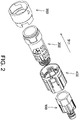
FIG. 2 is an exploded view of the connector shroud according to the first embodiment of the present invention. -
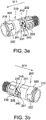
FIGS. 3a and 3b are different elevated perspective views of the inner housing of the connector shroud according to the first embodiment of the present invention. -
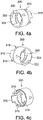
FIGS. 4a to 4c are different elevated perspective views of the coupling nut of the connector shroud according to the first embodiment of the present invention. -
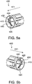
FIGS. 5a and 5b are different elevated perspective views of the lock nut of the connector shroud according to the first embodiment of the present invention. -
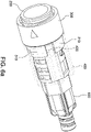
FIG. 6a is an elevated perspective view of the connector shroud according to the first embodiment of the present invention. -
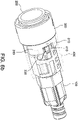
FIG. 6b is another elevated perspective view of the connector shroud according to the first embodiment of the present invention. -
FIG. 7 is an elevated perspective view of a conventional adapter. -
FIG. 8 is an elevated perspective view illustrating the combination of the connector shroud ofFIG. 6a and the conventional adapter ofFIG. 7 . -
FIG. 9 is an exploded view of the connector shroud according to the second embodiment of the present invention. -
FIGS. 10a and 10b are different elevated perspective views of the inner housing of the connector shroud according to the second embodiment of the present invention. -
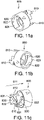
FIGS. 11a to 11c are different elevated perspective views of the coupling nut of the connector shroud according to the second embodiment of the present invention. -
FIGS. 12a and 12b are different elevated perspective views of the lock nut of the connector shroud according to the second embodiment of the present invention. -
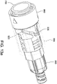
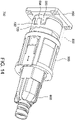
FIG. 13a is an elevated perspective view of the connector shroud according to the second embodiment of the present invention. -
FIG. 13b is another elevated perspective view of the connector shroud according to the second embodiment of the present invention. -
FIG. 14 is an elevated perspective view illustrating the combination of the connector shroud ofFIG. 13a and the conventional adapter ofFIG. 7 . - Referring to
FIG. 2 , which is an exploded view of the connector shroud according to the first embodiment of the present invention. As shown in the figure, the connector shroud includes acable gland 100, aninner housing 200, acoupling nut 300 and alock nut 400. Thecable gland 100, theinner housing 200, thecoupling nut 300 and thelock nut 400 may be constructed of plastics by an injection molding process. - The
cable gland 100 may be made from a flexible material and provide strain relief on cable (not shown) using materials and attachment techniques as are known in the art. Thecable gland 100 has a hollow body whose lengthwise direction is parallel to alongitudinal direction 511. Thecable gland 100 has a hexagonal shape at its front end for being coupled to theinner housing 200. - Referring to
FIGS. 3a and 3b , theinner housing 200 is hollow and has a cylindrical body whose lengthwise direction is parallel to thelongitudinal direction 511. Anannular groove 210 is formed at the front section of the outer surface of theinner housing 200 for receiving a sealing ring (not shown). Anannular protrusion 220 located behind theannular groove 210 is formed on the outer surface of theinner housing 200. Two mutuallyopposite recesses 222 are formed on theannular protrusion 220. Two identicalgrooved control links 230 are arranged on the outer surface of theinner housing 200 on two opposite sides. Each of thegrooved control links 230 has a closed endless configuration and substantially three functional sections including afirst section 231, asecond section 232 and athird section 233. Thesecond section 232 extends in thelongitudinal direction 511. Abump 242 is formed at the bottom of the center of thesecond section 232. Astep 241 is formed at the junction of thefirst section 231 and thesecond section 232. Thestep 241 is higher than the bottom of thesecond section 232. Astep 243 is formed at the junction of thefirst section 231 and thethird section 233. Thestep 243 is higher than the bottom of thefirst section 231. - Referring to
FIGS. 4a, 4b and 4c , thecoupling nut 300 is hollow and has a cylindrical body for being sleeved onto theinner housing 200. A plurality oftabs 310 with an arc-shaped cross-section protrudes from the rear end of thecoupling nut 300. Two mutually opposite receivingrecesses 320 are formed at the front section of the inner surface of thecoupling nut 300. A retainingwall 322 is arranged transversely in front of the receivingrecess 320 and agap 324 is formed on the left side of theretaining wall 322. - Referring to
FIGS. 5a and 5b , thelock nut 400 is hollow and has a cylindrical body for being sleeved onto theinner housing 200 and covering thetabs 310. Two mutuallyopposite protrusions 420 are formed at the front section of the inner surface of thelock nut 400 and have a lengthwise direction parallel to thelongitudinal direction 511. Two mutuallyopposite pins 410 are formed on the inner surface of thelock nut 400. In another embodiment, two mutuallyopposite openings 430 are formed on the lateral surface of thelock nut 400 and twocantilevers 440 are provided respectively in theopenings 430. Thecantilevers 440 extend from the lateral surface of thelock nut 400 and have a lengthwise direction parallel to thelongitudinal direction 511. The twopins 410 are respectively coupled to the front sections of the twocantilevers 440. - Referring to
FIGS. 6a and6b , which are two elevated perspective views illustrating the connector shroud according to the first embodiment of the present invention. The rear end of theinner housing 200 is coupled to the front end of thecable gland 100. Thecoupling nut 300 is sleeved onto the front section of theinner housing 200. Thelock nut 400 is sleeved onto the middle section of theinner casing 200 and covers thetabs 310 of thecoupling nut 300. The twoprojections 420 on the inner surface of thelock nut 400 are respectively arranged between two of thetabs 310 of thecoupling nut 300. The twopins 410 on the inner surface of thelock nut 400 are respectively located in the twogrooved control links 230 on theinner housing 200. The connectors to be shielded are arranged in the inner housing 200 (not shown). -
FIG. 7 shows aconventional flange 590, which is provided on an apparatus so that the connectors provided in the apparatus may be coupled to other connectors. Theflange 590 has a square body, and each of its four corners is provided with a bolt hole to enable theflange 590 to be mounted to the apparatus. Acircular opening 592 is arranged in the center of the body of theflange 590. Theopening 592 is surrounded by an annularouter flange part 591. Two mutuallyopposite positioning tabs 593 extend from theouter flange part 591 and twobumps 594 are respectively provided on thepositioning tabs 593. - Referring to
FIG. 8 , the connector shroud according to the first embodiment of the present invention may be mated with an object, such as theflange 590 ofFIG. 7 , so that the connectors provided in the connector shroud may be coupled with the connectors provided in the flange 590 (not shown). To mate with theflange 590, the front end of theinner housing 200 of the connector shroud is inserted into theouter flange part 591 of theflange 590 such that thepositioning tabs 593 of theflange 590 are respectively positioned in therecesses 222 on theannular protrusion 220 of theinner housing 200. Theinner housing 200 is restricted by theflange 590 and therefore cannot be rotated. Afterward thecoupling nut 300 is twisted clockwise to allow thebumps 594 of theflange 590 to enter the receiving recesses 320 from thegaps 324 on the left side of the retainingwalls 322 of thecoupling nut 300, respectively. Thecoupling nut 300 is now locked on theflange 590 and the connector shroud is mated with theflange 590. If it is desired to detach the connector shroud from theflange 590, thecoupling nut 300 is twisted counterclockwise such that thebumps 594 move out of the receivingrecesses 320 from thegaps 324, respectively. In other embodiments, thecoupling nut 300 is not limited to be coupled to theflange 590, and may be designed to be coupled to other objects. - Referring back to
FIG. 3 a , the twopins 410 of thelock nut 400 may respectively move in thegrooved control links 230 on theinner housing 200 in the arrow direction. More specifically, thepins 410 may respectively move in thegrooved control links 230 from thefirst section 231 through thesecond section 232 to thethird section 233, and then back to thefirst section 231. Thesteps pins 410 from moving in the incorrect direction. - When the
pins 410 are in thefirst sections 231, twisting thelock nut 400 clockwise allows thepins 410 to slide across thesteps 241 to thesecond sections 232 respectively and causes thelock nut 400 to move toward theflange 590. When thepins 410 are in thesecond sections 232, pulling thelock nut 400 backward allows thepins 410 to slide across thebumps 242 respectively and causes thelock nut 400 to move away from theflange 590. When a user pulls thelock nut 400 to cause thepins 410 to pass over thebumps 242 respectively, the user will feel a change in resistance. This change in resistance provides the user with tactile feedback. When thepins 410 are in thethird sections 233, twisting thelock nut 400 counterclockwise allows thepins 410 to slide across thesteps 243 back to thefirst sections 231 respectively. It should be noted that twisting thelock nut 400 will not cause theinner housing 200 to rotate. - In the connector shroud of the present invention, the
protrusions 420 on the inner surface of thelock nut 400 are each sandwiched by two of thetabs 310 of thecoupling nut 300 as shown inFIG. 6a . The twisting of thelock nut 400 may drive thecoupling nut 300 to rotate accordingly. Further, pulling thelock nut 400 backward will not pull thecoupling nut 300. When thepins 410 are moved from thefirst sections 231 to thesecond sections 232 respectively, thecoupling nut 300 rotates clockwise to be locked on theflange 590. If it is desired to unlock thecoupling nut 300, pulling thelock nut 400 backward and then twisting thelock nut 400 in the reverse direction cause thepins 410 to slide from thesecond sections 232 to thethird sections 233, respectively. - According to the connector shroud of the present invention, a user may twist the
lock nut 400 to rotate thecoupling nut 300 without need of directly twisting thecoupling nut 300. In this way there is no need to vacate the space beside thecoupling nut 300 for the user to twist thecoupling nut 300. Therefore, the installation density of the connectors can be improved. - Referring to
FIG. 9 , which is an exploded view of the connector shroud according to the second embodiment of the present invention. As shown in the figure, the connector shroud includes acable gland 600, aninner housing 700, acoupling nut 800 and alock nut 900. Thecable gland 600, theinner housing 700, thecoupling nut 800 and thelock nut 900 may be constructed of plastics by an injection molding process. - The
cable gland 600 may be made from a flexible material and provide strain relief on cable (not shown) using materials and attachment techniques as are known in the art. Thecable gland 600 has a hollow body whose lengthwise direction is parallel to alongitudinal direction 511. Thecable gland 600 has a hexagonal shape at its front end for being coupled to theinner housing 700. - Referring to
FIGS. 10a and 10b , theinner housing 700 is hollow and has a cylindrical body whose lengthwise direction is parallel to thelongitudinal direction 511. Anannular groove 710 is formed at the front section of the outer surface of theinner housing 700 for receiving a sealing ring (not shown). Anannular protrusion 720 located behind theannular groove 710 is formed on the outer surface of theinner housing 700. Two mutuallyopposite recesses 722 are formed on theannular protrusion 720. Two identicalgrooved control links 730 are arranged on the outer surface of theinner housing 700 on two opposite sides and extend in thelongitudinal direction 511. Abump 732 is formed at the bottom of the center of each of the grooved control links 730. - Referring to
FIGS. 11a, 11b and 11c , thecoupling nut 800 is hollow and has a cylindrical body for being sleeved onto theinner housing 700. Two mutually opposite receivingrecesses 820 are formed at the front section of the inner surface of thecoupling nut 800. A retainingwall 822 is arranged transversely in front of the receivingrecess 820 and agap 824 is formed on the left side of theretaining wall 822. Two mutuallyopposite tabs 810 with an arc-shaped cross-section protrude from the rear end of thecoupling nut 800. Two identical and mutuallyopposite control slots 830 are respectively formed on thetabs 810. Each of thecontrol slots 830 has substantially two functional sections including afirst section 831 and asecond section 832. Thefirst section 831 extends from the rear end of thetab 810 in thelongitudinal direction 511. Thesecond section 832 communicates with thefirst section 831 and extends from the front end of thefirst section 831 toward the front end of thecoupling nut 800 in a direction not parallel to thelongitudinal direction 511. - Referring to
FIGS. 12a and 12b , thelock nut 900 is hollow and has a cylindrical body for being sleeved onto theinner housing 700 and covering thetabs 810 of thecoupling nut 800. Two mutually oppositesecond pins 920 are formed at the front section of the inner surface of thelock nut 900. Two mutually oppositefirst pins 910 are formed on the inner surface of thelock nut 900. In another embodiment, two mutuallyopposite openings 930 are formed on the lateral surface of thelock nut 900 and twocantilevers 940 are provided respectively in theopenings 930. Thecantilevers 940 extend from the lateral surface of thelock nut 900 and have a lengthwise direction parallel to thelongitudinal direction 511. The twofirst pins 910 are respectively coupled to the front sections of the twocantilevers 940. - Referring to
FIGS. 13a and13b , which are two elevated perspective views illustrating the connector shroud according to the second embodiment of the present invention. The rear end of theinner housing 700 is coupled to the front end of thecable gland 600. Thecoupling nut 800 is sleeved onto the front section of theinner housing 700. Thelock nut 900 is sleeved onto the middle section of theinner casing 700 and covers thetabs 810 of thecoupling nut 800. The twofirst pins 910 on the inner surface of thelock nut 900 are respectively located in the twogrooved control links 730 on theinner housing 700. The twosecond pins 920 on the inner surface of thelock nut 900 are respectively arranged in the twocontrol slots 830 of thecoupling nut 800. The connectors to be shielded are arranged in the inner housing 700 (not shown). - Referring to
FIG. 14 , the connector shroud according to the second embodiment of the present invention may be mated with an object, such as theflange 590 ofFIG. 7 , so that the connectors provided in the connector shroud may be coupled with the connectors provided in the flange 590 (not shown). To mate with theflange 590, the front end of theinner housing 700 of the connector shroud is inserted into theouter flange part 591 of theflange 590 such that thepositioning tabs 593 of theflange 590 are respectively positioned in therecesses 722 on theannular protrusion 720 of theinner housing 700. Theinner housing 700 is restricted by theflange 590 and therefore cannot be rotated. Afterward thecoupling nut 800 is twisted clockwise to allow thebumps 594 of theflange 590 to enter the receiving recesses 820 from thegaps 824 on the left side of the retainingwalls 822 of thecoupling nut 800, respectively. Thecoupling nut 800 is now locked on theflange 590 and the connector shroud is mated with theflange 590. If it is desired to detach the connector shroud from theflange 590, thecoupling nut 800 is twisted counterclockwise such that thebumps 594 move out of the receivingrecesses 820 from thegaps 824, respectively. In other embodiments, thecoupling nut 800 is not limited to be coupled to theflange 590, and may be designed to be coupled to other objects. - Referring back to
FIG. 10a , the twofirst pins 910 of thelock nut 900 may respectively move in thegrooved control links 730 on theinner housing 700. When a user moves thelock nut 900 to cause thefirst pins 910 to pass over thebumps 732 respectively, the user will feel a change in resistance. This change in resistance provides the user with tactile feedback. - In the connector shroud of the present invention, the two
second pins 920 of thelock nut 900 may move respectively in the twocontrol slots 830 of thecoupling nut 800. When thesecond pins 920 are in thefirst sections 831 respectively, pulling or pushing thelock nut 900 will not cause thecoupling nut 800 to move because thefirst sections 831 are arranged parallel to thelongitudinal direction 511. When thesecond pins 920 are in thesecond sections 832 respectively, pushing thelock nut 900 forward causes thecoupling nut 800 to rotate clockwise and be locked on theflange 590. If it is desired to unlock thecoupling nut 800, pulling thelock nut 900 backward causes thecoupling nut 800 to rotate counterclockwise. - According to the connector shroud of the present invention, a user may move the
lock nut 900 longitudinally to rotate thecoupling nut 800 without need of directly twisting thecoupling nut 800. In this way there is no need to vacate the space beside thecoupling nut 800 for the user to twist thecoupling nut 800. Therefore, the installation density of the connectors can be improved.
Claims (10)
- A connector shroud, comprising:an inner housing (200) having a grooved control link (230) formed on an outer surface, the grooved control link (230) having a first section (231), a second section (232), and a third section (233) that communicate with each other, the second section (232) extending in a longitudinal direction (511);a coupling nut (300) sleeved onto the inner housing (200), the coupling nut (300) being configured to be coupled to an object; anda lock nut (400) sleeved onto the inner housing (200), the lock nut (400) comprising a pin (410) formed on an inner surface, the pin (410) being movable in the grooved control link (230), whereinwhen the pin (410) is in the second section (232), pulling the lock nut (400) causes the lock nut (400) to move away from the coupling nut (300), andwhen the pin (410) is in the first section (231) or the third section (233), twisting the lock nut (400) causes the coupling nut (300) to rotate.
- The connector shroud as claimed in claim 1, wherein the lock nut (400) further comprises a cantilever (440) extending in the longitudinal direction (511) in an opening (430), the pin (410) being disposed on the cantilever (440).
- The connector shroud as claimed in claim 1, wherein the coupling nut (300) comprises two tabs (310) extending from a rear end, the lock nut (400) further comprising a protrusion (420) formed on the inner surface, the protrusion (420) being disposed between the two tabs (310).
- The connector shroud as claimed in claim 1, wherein the inner housing (200) comprises a bump (242) formed in the second section (232) of the grooved control link (230) to provide a tactile feedback when the lock nut (400) is moved to cause the pin (410) to pass over the bump (242).
- The connector shroud as claimed in claim 1, wherein the inner housing (200) comprises a step (241) formed at the junction of the first and second sections (231, 232) of the grooved control link (230) to stop the pin (410) from moving from the second section (232) to the first section (231).
- A connector shroud, comprising:an inner housing (700) having a grooved control link (730) formed on an outer surface, the grooved control link (730) extending in a longitudinal direction (511);a coupling nut (800) sleeved onto the inner housing (700), the coupling nut (800) being configured to be coupled to an object, the coupling nut (800) comprising a tab (810) extending from a rear end, the tab (810) having a control slot (830) formed thereon, the control slot (830) having a first section (831) and a second section (832) communicating with the first section (831), the second section (832) extending in a direction not parallel to the longitudinal direction (511); anda lock nut (900) sleeved onto the inner housing (700), the lock nut (900) comprising a first pin (910) and a second pin (920) formed on an inner surface, the first pin (910) being movable in the grooved control link (730) and the second pin (920) being movable in the control slot (830), whereinwhen the second pin (920) is in the second section (832), a movement of the lock nut (900) causes the coupling nut (800) to rotate.
- The connector shroud as claimed in claim 6, wherein the first section (831) of the control slot (830) extends in the longitudinal direction (511).
- The connector shroud as claimed in claim 6, wherein the lock nut (900) further comprises a cantilever (940) extending in the longitudinal direction (511) in an opening (930), the first pin (910) being disposed on the cantilever (940).
- The connector shroud as claimed in claim 6, wherein the inner housing (700) comprises an annular protrusion (720) formed on the outer surface, two mutually opposite recesses (722) being formed on the annular protrusion (720).
- The connector shroud as claimed in claim 6, wherein the inner housing (700) comprises a bump (732) formed in the grooved control link (730) to provide a tactile feedback when the lock nut (900) is moved to cause the first pin (910) to pass over the bump (732).
Applications Claiming Priority (2)
| Application Number | Priority Date | Filing Date | Title |
|---|---|---|---|
| US202063035065P | 2020-06-05 | 2020-06-05 | |
| CN202010948195.8A CN113759470B (en) | 2020-06-05 | 2020-09-10 | Connector protective cover |
Publications (2)
| Publication Number | Publication Date |
|---|---|
| EP3920339A1 EP3920339A1 (en) | 2021-12-08 |
| EP3920339B1 true EP3920339B1 (en) | 2022-12-07 |
Family
ID=75111411
Family Applications (1)
| Application Number | Title | Priority Date | Filing Date |
|---|---|---|---|
| EP21163564.4A Active EP3920339B1 (en) | 2020-06-05 | 2021-03-18 | Connector shroud |
Country Status (5)
| Country | Link |
|---|---|
| US (1) | US11204472B1 (en) |
| EP (1) | EP3920339B1 (en) |
| CN (1) | CN113759470B (en) |
| ES (1) | ES2939703T3 (en) |
| FI (1) | FI3920339T3 (en) |
Families Citing this family (7)
| Publication number | Priority date | Publication date | Assignee | Title |
|---|---|---|---|---|
| EP3249434B1 (en) * | 2009-09-28 | 2021-11-24 | TE Connectivity Nederland B.V. | Sealing enclosure for a connector on a cable, such as a standardised fibre-optic connector |
| JP1684710S (en) * | 2020-11-25 | 2021-05-10 | ||
| JP1688083S (en) * | 2020-11-25 | 2021-06-21 | ||
| JP1688144S (en) * | 2020-11-25 | 2021-06-21 | ||
| TWI820765B (en) | 2021-08-16 | 2023-11-01 | 顏玉惠 | Connector shroud |
| CN116466443B (en) * | 2023-05-05 | 2025-08-22 | 平顶山天晟电气有限公司 | A docking structure and intelligent optical cable connector |
| CN117438839B (en) * | 2023-12-21 | 2024-03-15 | 四川宇飞连接电子有限公司 | Waterproof type two-way bi-polar face tensile connector |
Family Cites Families (17)
| Publication number | Priority date | Publication date | Assignee | Title |
|---|---|---|---|---|
| US5668904A (en) * | 1996-07-25 | 1997-09-16 | Northwest Fiberoptic Technologies Inc. | Fiber optic cable connector apparatus and method |
| US5662488A (en) * | 1996-10-31 | 1997-09-02 | Alden; Peter H. | Quick connect coupling system for rapidly joining connectors and/or other elongated bodies |
| DE19830671A1 (en) * | 1998-07-09 | 2000-01-20 | Kostal Leopold Gmbh & Co Kg | Lockable connector part for an electrical connector |
| CN100410565C (en) * | 2005-11-29 | 2008-08-13 | 重庆海扶(Hifu)技术有限公司 | A linear rotary dual motion system |
| JP4974625B2 (en) * | 2006-09-20 | 2012-07-11 | 中国電力株式会社 | Scaffolding bolt unit |
| AU2011253955A1 (en) * | 2007-02-27 | 2012-01-12 | Clipsal Australia Pty Limited | A Cord Clamp For An Electrical Connector Or Appliance |
| US7744286B2 (en) * | 2007-12-11 | 2010-06-29 | Adc Telecommunications, Inc. | Hardened fiber optic connection system with multiple configurations |
| CH701439A2 (en) * | 2009-07-06 | 2011-01-14 | Huber+Suhner Ag | Cable entry. |
| EP3249434B1 (en) * | 2009-09-28 | 2021-11-24 | TE Connectivity Nederland B.V. | Sealing enclosure for a connector on a cable, such as a standardised fibre-optic connector |
| EP2355283A1 (en) * | 2010-01-29 | 2011-08-10 | Tyco Electronics Raychem BVBA | Cable sealing device, cable termination and attaching device |
| US8985867B2 (en) * | 2011-09-07 | 2015-03-24 | Adc Telecommunications, Inc. | Optical fiber connection system |
| JP5866734B2 (en) * | 2012-12-27 | 2016-02-17 | ヒロセ電機株式会社 | Connector, connector device using the connector, and connector member used for the connector |
| CN104503035A (en) * | 2014-12-18 | 2015-04-08 | 中航光电科技股份有限公司 | Screw-joint locking optical fiber connector assembly |
| CN204361400U (en) * | 2015-01-08 | 2015-05-27 | 孙慧 | One can rosette for lock processed |
| US9755382B2 (en) | 2015-03-13 | 2017-09-05 | Senko Advanced Components, Inc. | Connector system with interchangeable connector modules for optical fibers, electrical conductors, or both |
| CN113196124B (en) * | 2018-10-16 | 2023-03-17 | 扇港元器件股份有限公司 | Springless retention structure for entry protected hybrid connector assembly |
| US10649152B1 (en) * | 2019-02-20 | 2020-05-12 | Muh-Chen Yang | Connector system |
-
2020
- 2020-09-10 CN CN202010948195.8A patent/CN113759470B/en active Active
- 2020-10-05 US US17/062,733 patent/US11204472B1/en active Active
-
2021
- 2021-03-18 FI FIEP21163564.4T patent/FI3920339T3/en active
- 2021-03-18 EP EP21163564.4A patent/EP3920339B1/en active Active
- 2021-03-18 ES ES21163564T patent/ES2939703T3/en active Active
Also Published As
| Publication number | Publication date |
|---|---|
| CN113759470B (en) | 2022-10-21 |
| US11204472B1 (en) | 2021-12-21 |
| EP3920339A1 (en) | 2021-12-08 |
| FI3920339T3 (en) | 2023-03-18 |
| US20210382247A1 (en) | 2021-12-09 |
| CN113759470A (en) | 2021-12-07 |
| ES2939703T3 (en) | 2023-04-26 |
Similar Documents
| Publication | Publication Date | Title |
|---|---|---|
| US11204472B1 (en) | Connector shroud | |
| US11822132B2 (en) | Optical communications connectors | |
| EP4137853B1 (en) | Connector shroud | |
| EP3699656B1 (en) | Connector system and dust protector thereof | |
| KR100195847B1 (en) | Duplex optical fiber connector and cables terminated therewith | |
| US12174433B2 (en) | Optical communications connectors | |
| TWI746160B (en) | Connector shroud | |
| CN219085176U (en) | Optical Communication Connector |
Legal Events
| Date | Code | Title | Description |
|---|---|---|---|
| PUAI | Public reference made under article 153(3) epc to a published international application that has entered the european phase |
Free format text: ORIGINAL CODE: 0009012 |
|
| STAA | Information on the status of an ep patent application or granted ep patent |
Free format text: STATUS: REQUEST FOR EXAMINATION WAS MADE |
|
| 17P | Request for examination filed |
Effective date: 20210727 |
|
| AK | Designated contracting states |
Kind code of ref document: A1 Designated state(s): AL AT BE BG CH CY CZ DE DK EE ES FI FR GB GR HR HU IE IS IT LI LT LU LV MC MK MT NL NO PL PT RO RS SE SI SK SM TR |
|
| B565 | Issuance of search results under rule 164(2) epc |
Effective date: 20210915 |
|
| REG | Reference to a national code |
Ref country code: DE Ref legal event code: R079 Ref document number: 602021000906 Country of ref document: DE Free format text: PREVIOUS MAIN CLASS: H01R0013516000 Ipc: G02B0006380000 |
|
| GRAP | Despatch of communication of intention to grant a patent |
Free format text: ORIGINAL CODE: EPIDOSNIGR1 |
|
| STAA | Information on the status of an ep patent application or granted ep patent |
Free format text: STATUS: GRANT OF PATENT IS INTENDED |
|
| RIC1 | Information provided on ipc code assigned before grant |
Ipc: H01R 13/625 20060101ALI20220523BHEP Ipc: H01R 13/516 20060101ALI20220523BHEP Ipc: G02B 6/38 20060101AFI20220523BHEP |
|
| INTG | Intention to grant announced |
Effective date: 20220617 |
|
| GRAS | Grant fee paid |
Free format text: ORIGINAL CODE: EPIDOSNIGR3 |
|
| GRAA | (expected) grant |
Free format text: ORIGINAL CODE: 0009210 |
|
| STAA | Information on the status of an ep patent application or granted ep patent |
Free format text: STATUS: THE PATENT HAS BEEN GRANTED |
|
| AK | Designated contracting states |
Kind code of ref document: B1 Designated state(s): AL AT BE BG CH CY CZ DE DK EE ES FI FR GB GR HR HU IE IS IT LI LT LU LV MC MK MT NL NO PL PT RO RS SE SI SK SM TR |
|
| REG | Reference to a national code |
Ref country code: GB Ref legal event code: FG4D |
|
| REG | Reference to a national code |
Ref country code: CH Ref legal event code: EP Ref country code: AT Ref legal event code: REF Ref document number: 1536625 Country of ref document: AT Kind code of ref document: T Effective date: 20221215 |
|
| REG | Reference to a national code |
Ref country code: DE Ref legal event code: R096 Ref document number: 602021000906 Country of ref document: DE |
|
| REG | Reference to a national code |
Ref country code: IE Ref legal event code: FG4D |
|
| REG | Reference to a national code |
Ref country code: SE Ref legal event code: TRGR |
|
| REG | Reference to a national code |
Ref country code: LT Ref legal event code: MG9D |
|
| REG | Reference to a national code |
Ref country code: NL Ref legal event code: MP Effective date: 20221207 |
|
| REG | Reference to a national code |
Ref country code: ES Ref legal event code: FG2A Ref document number: 2939703 Country of ref document: ES Kind code of ref document: T3 Effective date: 20230426 |
|
| PG25 | Lapsed in a contracting state [announced via postgrant information from national office to epo] |
Ref country code: NO Free format text: LAPSE BECAUSE OF FAILURE TO SUBMIT A TRANSLATION OF THE DESCRIPTION OR TO PAY THE FEE WITHIN THE PRESCRIBED TIME-LIMIT Effective date: 20230307 Ref country code: LT Free format text: LAPSE BECAUSE OF FAILURE TO SUBMIT A TRANSLATION OF THE DESCRIPTION OR TO PAY THE FEE WITHIN THE PRESCRIBED TIME-LIMIT Effective date: 20221207 |
|
| REG | Reference to a national code |
Ref country code: AT Ref legal event code: MK05 Ref document number: 1536625 Country of ref document: AT Kind code of ref document: T Effective date: 20221207 |
|
| PG25 | Lapsed in a contracting state [announced via postgrant information from national office to epo] |
Ref country code: RS Free format text: LAPSE BECAUSE OF FAILURE TO SUBMIT A TRANSLATION OF THE DESCRIPTION OR TO PAY THE FEE WITHIN THE PRESCRIBED TIME-LIMIT Effective date: 20221207 Ref country code: PL Free format text: LAPSE BECAUSE OF FAILURE TO SUBMIT A TRANSLATION OF THE DESCRIPTION OR TO PAY THE FEE WITHIN THE PRESCRIBED TIME-LIMIT Effective date: 20221207 Ref country code: LV Free format text: LAPSE BECAUSE OF FAILURE TO SUBMIT A TRANSLATION OF THE DESCRIPTION OR TO PAY THE FEE WITHIN THE PRESCRIBED TIME-LIMIT Effective date: 20221207 Ref country code: HR Free format text: LAPSE BECAUSE OF FAILURE TO SUBMIT A TRANSLATION OF THE DESCRIPTION OR TO PAY THE FEE WITHIN THE PRESCRIBED TIME-LIMIT Effective date: 20221207 Ref country code: GR Free format text: LAPSE BECAUSE OF FAILURE TO SUBMIT A TRANSLATION OF THE DESCRIPTION OR TO PAY THE FEE WITHIN THE PRESCRIBED TIME-LIMIT Effective date: 20230308 |
|
| PG25 | Lapsed in a contracting state [announced via postgrant information from national office to epo] |
Ref country code: NL Free format text: LAPSE BECAUSE OF FAILURE TO SUBMIT A TRANSLATION OF THE DESCRIPTION OR TO PAY THE FEE WITHIN THE PRESCRIBED TIME-LIMIT Effective date: 20221207 |
|
| PG25 | Lapsed in a contracting state [announced via postgrant information from national office to epo] |
Ref country code: SM Free format text: LAPSE BECAUSE OF FAILURE TO SUBMIT A TRANSLATION OF THE DESCRIPTION OR TO PAY THE FEE WITHIN THE PRESCRIBED TIME-LIMIT Effective date: 20221207 Ref country code: RO Free format text: LAPSE BECAUSE OF FAILURE TO SUBMIT A TRANSLATION OF THE DESCRIPTION OR TO PAY THE FEE WITHIN THE PRESCRIBED TIME-LIMIT Effective date: 20221207 Ref country code: PT Free format text: LAPSE BECAUSE OF FAILURE TO SUBMIT A TRANSLATION OF THE DESCRIPTION OR TO PAY THE FEE WITHIN THE PRESCRIBED TIME-LIMIT Effective date: 20230410 Ref country code: EE Free format text: LAPSE BECAUSE OF FAILURE TO SUBMIT A TRANSLATION OF THE DESCRIPTION OR TO PAY THE FEE WITHIN THE PRESCRIBED TIME-LIMIT Effective date: 20221207 Ref country code: CZ Free format text: LAPSE BECAUSE OF FAILURE TO SUBMIT A TRANSLATION OF THE DESCRIPTION OR TO PAY THE FEE WITHIN THE PRESCRIBED TIME-LIMIT Effective date: 20221207 Ref country code: AT Free format text: LAPSE BECAUSE OF FAILURE TO SUBMIT A TRANSLATION OF THE DESCRIPTION OR TO PAY THE FEE WITHIN THE PRESCRIBED TIME-LIMIT Effective date: 20221207 |
|
| PG25 | Lapsed in a contracting state [announced via postgrant information from national office to epo] |
Ref country code: SK Free format text: LAPSE BECAUSE OF FAILURE TO SUBMIT A TRANSLATION OF THE DESCRIPTION OR TO PAY THE FEE WITHIN THE PRESCRIBED TIME-LIMIT Effective date: 20221207 Ref country code: IS Free format text: LAPSE BECAUSE OF FAILURE TO SUBMIT A TRANSLATION OF THE DESCRIPTION OR TO PAY THE FEE WITHIN THE PRESCRIBED TIME-LIMIT Effective date: 20230407 Ref country code: AL Free format text: LAPSE BECAUSE OF FAILURE TO SUBMIT A TRANSLATION OF THE DESCRIPTION OR TO PAY THE FEE WITHIN THE PRESCRIBED TIME-LIMIT Effective date: 20221207 |
|
| REG | Reference to a national code |
Ref country code: DE Ref legal event code: R097 Ref document number: 602021000906 Country of ref document: DE |
|
| PLBE | No opposition filed within time limit |
Free format text: ORIGINAL CODE: 0009261 |
|
| STAA | Information on the status of an ep patent application or granted ep patent |
Free format text: STATUS: NO OPPOSITION FILED WITHIN TIME LIMIT |
|
| PG25 | Lapsed in a contracting state [announced via postgrant information from national office to epo] |
Ref country code: MC Free format text: LAPSE BECAUSE OF FAILURE TO SUBMIT A TRANSLATION OF THE DESCRIPTION OR TO PAY THE FEE WITHIN THE PRESCRIBED TIME-LIMIT Effective date: 20221207 Ref country code: DK Free format text: LAPSE BECAUSE OF FAILURE TO SUBMIT A TRANSLATION OF THE DESCRIPTION OR TO PAY THE FEE WITHIN THE PRESCRIBED TIME-LIMIT Effective date: 20221207 |
|
| 26N | No opposition filed |
Effective date: 20230908 |
|
| PG25 | Lapsed in a contracting state [announced via postgrant information from national office to epo] |
Ref country code: SI Free format text: LAPSE BECAUSE OF FAILURE TO SUBMIT A TRANSLATION OF THE DESCRIPTION OR TO PAY THE FEE WITHIN THE PRESCRIBED TIME-LIMIT Effective date: 20221207 |
|
| REG | Reference to a national code |
Ref country code: BE Ref legal event code: MM Effective date: 20230331 |
|
| PG25 | Lapsed in a contracting state [announced via postgrant information from national office to epo] |
Ref country code: LU Free format text: LAPSE BECAUSE OF NON-PAYMENT OF DUE FEES Effective date: 20230318 |
|
| REG | Reference to a national code |
Ref country code: IE Ref legal event code: MM4A |
|
| PG25 | Lapsed in a contracting state [announced via postgrant information from national office to epo] |
Ref country code: IE Free format text: LAPSE BECAUSE OF NON-PAYMENT OF DUE FEES Effective date: 20230318 |
|
| PG25 | Lapsed in a contracting state [announced via postgrant information from national office to epo] |
Ref country code: BE Free format text: LAPSE BECAUSE OF NON-PAYMENT OF DUE FEES Effective date: 20230331 |
|
| PG25 | Lapsed in a contracting state [announced via postgrant information from national office to epo] |
Ref country code: IT Free format text: LAPSE BECAUSE OF FAILURE TO SUBMIT A TRANSLATION OF THE DESCRIPTION OR TO PAY THE FEE WITHIN THE PRESCRIBED TIME-LIMIT Effective date: 20221207 |
|
| PG25 | Lapsed in a contracting state [announced via postgrant information from national office to epo] |
Ref country code: BG Free format text: LAPSE BECAUSE OF FAILURE TO SUBMIT A TRANSLATION OF THE DESCRIPTION OR TO PAY THE FEE WITHIN THE PRESCRIBED TIME-LIMIT Effective date: 20221207 |
|
| PG25 | Lapsed in a contracting state [announced via postgrant information from national office to epo] |
Ref country code: BG Free format text: LAPSE BECAUSE OF FAILURE TO SUBMIT A TRANSLATION OF THE DESCRIPTION OR TO PAY THE FEE WITHIN THE PRESCRIBED TIME-LIMIT Effective date: 20221207 |
|
| PGFP | Annual fee paid to national office [announced via postgrant information from national office to epo] |
Ref country code: ES Payment date: 20250416 Year of fee payment: 5 |
|
| PG25 | Lapsed in a contracting state [announced via postgrant information from national office to epo] |
Ref country code: CY Free format text: LAPSE BECAUSE OF FAILURE TO SUBMIT A TRANSLATION OF THE DESCRIPTION OR TO PAY THE FEE WITHIN THE PRESCRIBED TIME-LIMIT; INVALID AB INITIO Effective date: 20210318 |
|
| PG25 | Lapsed in a contracting state [announced via postgrant information from national office to epo] |
Ref country code: HU Free format text: LAPSE BECAUSE OF FAILURE TO SUBMIT A TRANSLATION OF THE DESCRIPTION OR TO PAY THE FEE WITHIN THE PRESCRIBED TIME-LIMIT; INVALID AB INITIO Effective date: 20210318 |
|
| PGFP | Annual fee paid to national office [announced via postgrant information from national office to epo] |
Ref country code: CH Payment date: 20250701 Year of fee payment: 5 |
|
| PG25 | Lapsed in a contracting state [announced via postgrant information from national office to epo] |
Ref country code: TR Free format text: LAPSE BECAUSE OF FAILURE TO SUBMIT A TRANSLATION OF THE DESCRIPTION OR TO PAY THE FEE WITHIN THE PRESCRIBED TIME-LIMIT Effective date: 20221207 |
|
| PGFP | Annual fee paid to national office [announced via postgrant information from national office to epo] |
Ref country code: SE Payment date: 20260323 Year of fee payment: 6 |
|
| PGFP | Annual fee paid to national office [announced via postgrant information from national office to epo] |
Ref country code: GB Payment date: 20260309 Year of fee payment: 6 |
|
| PGFP | Annual fee paid to national office [announced via postgrant information from national office to epo] |
Ref country code: DE Payment date: 20260318 Year of fee payment: 6 |
|
| PGFP | Annual fee paid to national office [announced via postgrant information from national office to epo] |
Ref country code: FI Payment date: 20260320 Year of fee payment: 6 |
|
| PGFP | Annual fee paid to national office [announced via postgrant information from national office to epo] |
Ref country code: FR Payment date: 20260325 Year of fee payment: 6 |