EP3920329A1 - Antenna device - Google Patents
Antenna device Download PDFInfo
- Publication number
- EP3920329A1 EP3920329A1 EP19918211.4A EP19918211A EP3920329A1 EP 3920329 A1 EP3920329 A1 EP 3920329A1 EP 19918211 A EP19918211 A EP 19918211A EP 3920329 A1 EP3920329 A1 EP 3920329A1
- Authority
- EP
- European Patent Office
- Prior art keywords
- antenna
- scanning angle
- radome
- layers
- transmission characteristic
- Prior art date
- Legal status (The legal status is an assumption and is not a legal conclusion. Google has not performed a legal analysis and makes no representation as to the accuracy of the status listed.)
- Granted
Links
Images







Classifications
-
- H—ELECTRICITY
- H01—ELECTRIC ELEMENTS
- H01Q—ANTENNAS, i.e. RADIO AERIALS
- H01Q1/00—Details of, or arrangements associated with, antennas
- H01Q1/42—Housings not intimately mechanically associated with radiating elements, e.g. radome
- H01Q1/422—Housings not intimately mechanically associated with radiating elements, e.g. radome comprising two or more layers of dielectric material
-
- H—ELECTRICITY
- H01—ELECTRIC ELEMENTS
- H01Q—ANTENNAS, i.e. RADIO AERIALS
- H01Q1/00—Details of, or arrangements associated with, antennas
- H01Q1/42—Housings not intimately mechanically associated with radiating elements, e.g. radome
- H01Q1/421—Means for correcting aberrations introduced by a radome
-
- H—ELECTRICITY
- H01—ELECTRIC ELEMENTS
- H01Q—ANTENNAS, i.e. RADIO AERIALS
- H01Q15/00—Devices for reflection, refraction, diffraction or polarisation of waves radiated from an antenna, e.g. quasi-optical devices
- H01Q15/0006—Devices acting selectively as reflecting surface, as diffracting or as refracting device, e.g. frequency filtering or angular spatial filtering devices
- H01Q15/0013—Devices acting selectively as reflecting surface, as diffracting or as refracting device, e.g. frequency filtering or angular spatial filtering devices said selective devices working as frequency-selective reflecting surfaces, e.g. FSS, dichroic plates, surfaces being partly transmissive and reflective
- H01Q15/0026—Devices acting selectively as reflecting surface, as diffracting or as refracting device, e.g. frequency filtering or angular spatial filtering devices said selective devices working as frequency-selective reflecting surfaces, e.g. FSS, dichroic plates, surfaces being partly transmissive and reflective said selective devices having a stacked geometry or having multiple layers
-
- H—ELECTRICITY
- H01—ELECTRIC ELEMENTS
- H01Q—ANTENNAS, i.e. RADIO AERIALS
- H01Q3/00—Arrangements for changing or varying the orientation or the shape of the directional pattern of the waves radiated from an antenna or antenna system
- H01Q3/26—Arrangements for changing or varying the orientation or the shape of the directional pattern of the waves radiated from an antenna or antenna system varying the relative phase or relative amplitude of energisation between two or more active radiating elements; varying the distribution of energy across a radiating aperture
-
- H—ELECTRICITY
- H01—ELECTRIC ELEMENTS
- H01Q—ANTENNAS, i.e. RADIO AERIALS
- H01Q13/00—Waveguide horns or mouths; Slot antennas; Leaky-waveguide antennas; Equivalent structures causing radiation along the transmission path of a guided wave
- H01Q13/02—Waveguide horns
-
- H—ELECTRICITY
- H01—ELECTRIC ELEMENTS
- H01Q—ANTENNAS, i.e. RADIO AERIALS
- H01Q15/00—Devices for reflection, refraction, diffraction or polarisation of waves radiated from an antenna, e.g. quasi-optical devices
- H01Q15/14—Reflecting surfaces; Equivalent structures
- H01Q15/16—Reflecting surfaces; Equivalent structures curved in two dimensions [2D], e.g. paraboloidal
Definitions
- the present invention relates to an antenna device including a radome covering the antenna.
- the antenna may be equipped with a radome that covers a beam emitting surface to protect it from the external environment such as wind, rain or dust.
- a radome that covers a beam emitting surface to protect it from the external environment such as wind, rain or dust.
- the attenuation of a beam intensity of a beam emitted by the antenna at a scanning angle other than a specific scanning angle is larger than that of a beam emitted at the specific scanning angle. Therefore, it is necessary to suppress the attenuation of the beam intensity depending on the scanning angle of the beam in the radome.
- the antenna device described in Patent Literature 1 has a structure in which the thickness of the radome is 1/2 wavelength or 1/4 wavelength in a narrower-angle direction than a predetermined direction when viewed from the antenna, and the thickness of the radome in a wider-angle direction than a predetermined direction when viewed from the antenna is thicker than the thickness of the radome in the narrow-angle direction. Therefore, in the antenna device, one surface of the radome has a step.
- Patent Literature 1 JP 2018-137563A
- the thickness of the radome in the narrower-angle direction than the predetermined direction when viewed from the antenna is a constraint on the design of the antenna device. Further, if the thickness of the radome in the narrow-angle direction is set to the thickness of 1/2 wavelength or 1/4 wavelength of a high frequency band such as millimeter wave, there is a problem that the mechanical strength of the radome is weakened.
- the present invention has been made to solve the above-mentioned problems, and has an object to suppress the attenuation of the beam intensity depending on the scanning angle of the beam in the radome without providing a step on the surface of the radome in an antenna device provided with the radome covering the antenna.
- the antenna device includes an antenna and a radome that covers the antenna, in which the radome includes a first part, a second part and a third part each with a surface which is flush to each other, the first part has a beam transmission characteristic corresponding to a scanning angle of 0 degrees of a beam emitted by the antenna with an emission direction directed toward the first part, the second part has a beam transmission characteristic corresponding to a first scanning angle of a beam emitted by the antenna with an emission direction directed toward the second part, and the third part has a beam transmission characteristic corresponding to a second scanning angle of a beam emitted by the antenna with an emission direction directed toward the third part.
- an antenna device provided with a radome covering the antenna, it is possible to suppress the attenuation of the beam intensity depending on the scanning angle of the beam emitted by the antenna in the radome without providing a step on the surface of the radome.
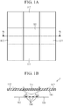
- FIG. 1A is a plan view showing the configuration of an antenna device 1 according to a first embodiment.
- FIG. 1B is a cross-sectional view of the antenna device 1 whose cross section is a plane cut along a dotted line ⁇ 1 of FIG. 1A .
- the antenna device 1 includes a planar antenna 100 and a radome 110 that covers the planar antenna.
- the radome 110 includes a first part 111, a second part 112, and a third part 113which are flush with each other. More specifically, the second part 112 is adjacent to one end A of the first part and the third part 113 is adjacent to the other end B of the first part. Note that, the second part 112 and the third part 113 can be integrally formed together with each part of the radome 110 other than the first part 111 so as to surround the first part 111.
- the planar antenna 100 includes a dielectric substrate 102 and a plurality of antenna elements 101 installed side by side on the dielectric substrate 102.
- the planar antenna 100 emits a beam toward the radome 110 from a beam emitting surface composed of the surfaces of the plurality of antenna elements 101.
- the planar antenna 100 can change the emission direction of the beam by changing the scanning angle of the beam by using a plurality of antenna elements 101. Note that, in the present embodiment, the configuration in which the planar antenna 100 is used as the antenna covered by the radome 110 will be described, but the antenna covered by the radome 110 may be an antenna capable of changing the beam emission direction, and is not limited to the configuration.
- the first part 111 is located in a direction of a scanning angle of 0 degrees with respect to the planar antenna 100
- the second part 112 is located in a direction of a first scanning angle ⁇ 1 with respect to the planar antenna 100
- the third part 113 is located in a direction of a second scanning angle ⁇ 2 with respect to the planar antenna 100.
- one end A of the first part 111 is located in a direction of a scanning angle narrower than the first scanning angle ⁇ 1 with respect to one end C of the beam emitting surface composed of the surfaces of the plurality of antenna elements 101 included in the planar antenna 100, and the other end B of the first part 111 is located in a direction of a scanning angle narrower than the second scanning angle ⁇ 2 with respect to the other end D of the planar antenna 100.
- the scanning angle of the beam emitted by the planar antenna 100 is a scanning angle using a line orthogonal to a beam emitting surface of the planar antenna 100 and the surface of the first part 111 facing the beam emitting surface as a reference line, and it is assumed that the scanning angle on the second part 112 side is a positive scanning angle, and the scanning angle on the third part 113 side is a negative scanning angle.
- the size of the first part 111 is defined by the first scanning angle ⁇ 1 and the second scanning angle ⁇ 2 , but the size of the first part 111 may be defined by the size of the beam emitting surface of the planar antenna 100.
- the first part 111 has a surface facing the beam emitting surface of the planar antenna 100, and the size of the surface of the first part 111 is equivalent to or larger than the size of the beam emitting surface of the planar antenna.
- the first part 111 of the radome 110 has a beam transmission characteristic corresponding to a scanning angle of 0 degrees of a beam emitted by the planar antenna 100 with an emission direction directed toward the first part 111.
- the "beam transmission characteristic” means the ease of transmission of the beam incident from a specific direction in the radome 110.
- the first part 111 has a beam transmission characteristic corresponding to a scanning angle of 0 degrees
- the first part 111 has a characteristic of more easily transmitting a beam when the planar antenna 100 emits the beam at a scanning angle of 0 degrees than when the planar antenna 100 emits a beam at a scanning angle other than 0 degrees.
- the second part 112 of the radome 110 has a beam transmission characteristic corresponding to the first scanning angle ⁇ 1 of the beam emitted by the planar antenna 100 with the emission direction directed toward the second part 112.
- the third part 113 of the radome 110 has a beam transmission characteristic corresponding to the second scanning angle ⁇ 2 of the beam emitted by the planar antenna 100 with the emission direction directed toward the third part 113.
- each of the first part 111, the second part 112, and the third part 113 is composed of one or more layers.
- the first part 111 and the second part 112 differ in at least one or more of the number of layers, the material of the layer, and the thickness of each layer when the one or more layers are a plurality of layers, and thus differ in the beam transmission characteristic.
- the first part 111 and the third part 113 differ in at least one or more of the number of layers, the material of the layer, and the thickness of each layer when the one or more layers are a plurality of layers, and thus differ in the beam transmission characteristic.
- An example of the material of the layer is a dielectric or the like.
- the number of layers, the material of the layer, and the thickness of each layer when the one or more layers are a plurality of layers can be the same in the second part 112 and the third part 113. In that case, the beam transmission characteristic of the second part 112 and the beam transmission characteristic of the third part 113 are the same.
- FIG. 2A is a cross-sectional view of a radome 120 according to a first specific example of the first embodiment.
- each of a first part 121, a second part 122, and a third part 123 of the radome 120 is composed of one layer.
- the first part 111 and the second part 112 differ in the material of the layer, and thus differ in the beam transmission characteristic.
- the first part 111 and the third part 113 differ in the material of the layer, and thus differ in the beam transmission characteristic.
- FIG. 2B is a cross-sectional view of a radome 130 according to a second specific example of the first embodiment.
- each of a first part 131, a second part 132, and a third part 133 of the radome 130 is composed of three layers.
- the first part 111 and the second part 112 differ in the material of any one or more layers of the three layers, and thus differ in the beam transmission characteristic.
- the first part 111 and the third part 113 differ in the material of any one or more layers of the three layers, and thus differ in the beam transmission characteristic.
- FIG. 2C is a cross-sectional view of a radome 140 according to a third specific example of the first embodiment.
- a first part 141 of the radome 140 is composed of three layers, and each of a second part 142 and a third part 143 is composed of two layers.
- the first part 141 and the second part 142 differ in the material of layer, the number of layers, and the thickness of each layer, and thus differ in the beam transmission characteristic.
- the first part 141 and the third part 143 differ in the material of layer, the number of layers, and the thickness of each layer, and thus differ in the beam transmission characteristic.
- FIG. 2D is a cross-sectional view of a radome 150 according to a modified example of the first embodiment.
- each of a first part 151, a second part 152, and a third part 153 of the radome 150 is composed of one curved layer.
- a planar radome is shown, but as in the radome 150 of FIG. 2D , the radome covering the planar antenna 100 may be curved. Also, the curvature of the curve of such a radome can be any value.
- the antenna device 1 includes a planar antenna 100 as an antenna and a radome covering the planar antenna 100
- the radome 110 includes a first part 111, a second part 112, and a third part 113 each with a surface which is flush to each other
- the first part 111 has a beam transmission characteristic corresponding to a scanning angle of 0 degrees of the beam emitted by the planar antenna 100 with an emission direction directed toward the first part 111
- the second part 112 has a beam transmission characteristic corresponding to a first scanning angle ⁇ 1 of the beam emitted by the planar antenna 100 with the emission direction directed toward the second part 112
- the third part 113 has a beam transmission characteristic corresponding to a second scanning angle ⁇ 2 of the beam emitted by the planar antenna 100 with the emission direction directed toward the third part 113.
- the surfaces of the first part 111, the second part 112, and the third part 113 are flush with each other.
- the first part 111 suppresses the attenuation of the beam intensity when the planar antenna 100 emits a beam at a scanning angle of 0 degrees.
- the second part 112 suppresses the attenuation of the beam intensity when the planar antenna 100 emits a beam at the first scanning angle.
- the third part 113 suppresses the attenuation of the beam intensity when the planar antenna 100 emits a beam at the second scanning angle. This makes it possible to suppress the attenuation of the beam intensity depending on the scanning angle of the beam in the radome without providing a step on the surface of the radome.
- each of the first part 111, the second part 112, and the third part 113 is composed of one or more layers, and the first part 111 and the second part 112 differ in at least one or more of the number of layers, the material of the layer, and the thickness of each layer when the one or more layers are a plurality of layers, and thus differ in the beam transmission characteristic, and the first part 111 and the third part 113 differ in at least one or more of the number of layers, the material of the layer, and the thickness of each layer when the one or more layers are a plurality of layers, and thus differ in the beam transmission characteristic.
- At least one or more of the number of layers, the material of the layer, and the thickness of each layer when the one or more layers are a plurality of layers are made different from each other, and thereby it is possible to suppress the attenuation of the beam intensity depending on the scanning angle of the beam in the radome without providing a step on the surface of the radome.
- the antenna is a planar antenna 100
- the second part 112 is adjacent to one end A of the first part 111
- the third part 113 is adjacent to the other end B of the first part 111.
- the second part 112 covers the planar antenna 100, and in a region adj acent to the other end B of the first part 111, the third part 113 covers the planar antenna 100.
- the first part 111 is located in the direction of a scanning angle of 0 degrees with respect to the planar antenna 100
- the second part 112 is located in the direction of the first scanning angle ⁇ 1 with respect to the planar antenna 100
- the third part 113 is located in the direction of the second scanning angle ⁇ 2 with respect to the planar antenna 100.
- the first part 111 is disposed so as to suppress the attenuation of the beam intensity when the planar antenna 100 emits a beam in the direction of a scanning angle of 0 degrees.
- the second part 112 is disposed so as to suppress the attenuation of the beam intensity when the planar antenna 100 emits a beam in the direction of the first scanning angle.
- the third part 113 is disposed so as to suppress the attenuation of the beam intensity when the planar antenna 100 emits a beam in the direction of the second scanning angle. This makes it possible to suppress the attenuation of the beam intensity depending on the scanning angle of the beam in the radome.
- the configuration in which the radome 110 includes three parts, the first part 111, the second part 112, and the third part 113, has been described.
- a configuration in which a radome 210 further includes one or more parts each having a surface flush with each surface of a first part 211, a second part 212, and a third part 213 will be described.
- FIG. 3A is a plan view showing a configuration of an antenna device 2 according to the second embodiment.
- FIG. 3B is a cross-sectional view of the antenna device 2 whose cross section is a plane cut along a dotted line ⁇ 2 of FIG. 3A .
- the antenna device 2 according to the second embodiment differs from the antenna device 1 according to the first embodiment in that the radome 210 further includes a fourth part 214 and a fifth part 215 in addition to the first part 211, the second part 212, and the third part 213, and the size of a surface S 1 of the first part 211 facing the beam emitting surface of the planar antenna 100 is equivalent to the size of a beam emitting surface S 2 of the planar antenna 100.
- the fourth part 214 and the fifth part 215 can be integrally formed so as to surround the first part 211, the second part 212, and the third part 213.
- the radome 210 includes the fourth part 214 adjacent to the end E of the second part 212 and the fifth part 215 adjacent to the end F of the third part 213.
- the end E of the second part 212 is the end of the second part 212 opposite to the end adjacent to the first part 211
- the end F of the third part 213 is the end of the third part 213 opposite to the end adjacent to the first part 211.
- the fourth part 214 is located in a direction of a third scanning angle ⁇ 3 with respect to the planar antenna 100
- the fifth part 215 is located in a direction of a fourth scanning angle ⁇ 4 with respect to the planar antenna 100.
- the end of the fourth part 214 adjacent to the end E of the second part 212 is located in a direction of a scanning angle wider than the third scanning angle ⁇ 3 with respect to one end C of a beam emitting surface composed of the surfaces of a plurality of antenna elements 101 included in the planar antenna 100.
- the end of the fifth part 215 adjacent to the end F of the third part 213 is located in a direction of a scanning angle wider than the fourth scanning angle ⁇ 4 with respect to the other end D of the beam emitting surface composed of the surfaces of a plurality of antenna elements 101 included in the planar antenna 100.
- the second part 212 is located between the first part 211 and the fourth part 214 defined as described above
- the third part 213 is located between the first part 211 and the fifth part 215 defined as described above.
- the first part 211 of the radome 210 has a beam transmission characteristic corresponding to a scanning angle of 0 degrees of the beam emitted by the planar antenna 100 with the emission direction directed toward the first part 211.
- the fourth part 214 of the radome 210 has a beam transmission characteristic corresponding to the third scanning angle ⁇ 3 of the beam emitted by the planar antenna 100 with the emission direction directed toward the fourth part 214.
- the fifth part 215 of the radome 210 has a beam transmission characteristic corresponding to the fourth scanning angle ⁇ 4 of the beam emitted by the planar antenna 100 with the emission direction directed toward the fifth part 215.
- the second part 212 of the radome 210 has a beam transmission characteristic corresponding to the first scanning angle between the scanning angle of 0 degrees and the third scanning angle ⁇ 3 .
- the fifth part 215 of the radome 210 has a beam transmission characteristic corresponding to the second scanning angle between the scanning angle of 0 degrees and the fourth scanning angle ⁇ 4 .
- FIG. 4 is a cross-sectional view showing a configuration of an antenna device 20 according to a specific example of the second embodiment.
- the end of a fourth part 224 adjacent to the end E of a second part 222 is located in a direction of a scanning angle narrower than a scanning angle of 70 degrees with respect to the other end D of the beam emitting surface composed of the surfaces of a plurality of antenna elements 101 included in the planar antenna 100.
- the end of a fifth part 225 adjacent to the end F of a third part 223 is located in a direction of a scanning angle narrower than a scanning angle of -70 degrees with respect to one end C of a beam emitting surface composed of the surfaces of a plurality of antenna elements 101 included in the planar antenna 100.
- the planar antenna 100 of the antenna device 20 includes a plurality of 12 ⁇ 12 antenna elements 101.
- the beam transmission characteristics of the first part 221, the second part 222, the third part 223, the fourth part 224, and the fifth part 225 included in the radome 220 will be described below.
- the first part 221 of the radome 220 has a beam transmission characteristic corresponding to a scanning angle of 0 degrees of the beam emitted by the planar antenna 100 with the emission direction directed toward the first part 221.
- the second part 222 of the radome 220 has a beam transmission characteristic corresponding to a first scanning angle of 35 degrees of the beam emitted by the planar antenna 100 with the emission direction directed toward the second part 222.
- the third part 223 of the radome 220 has a beam transmission characteristic corresponding to a second scanning angle of -35 degrees of the beam emitted by the planar antenna 100 with the emission direction directed toward the third part 223.
- the fourth part 224 of the radome 220 has a beam transmission characteristic corresponding to a third scanning angle of 70 degrees of the beam emitted by the planar antenna 100 with the emission direction directed toward the fourth part 224.
- the fifth part 225 of the radome 220 has a beam transmission characteristic corresponding to a fourth scanning angle of -70 degrees of the beam emitted by the planar antenna 100 with the emission direction directed toward the fifth part 225.
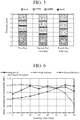
- FIG. 5 is a graph showing a layer structure of the radome 220 according to a specific example of the second embodiment.
- the bar graph on the left side of FIG. 5 shows each layer of the first part 221
- the bar graph in the middle of FIG. 5 shows each layer of the second part 222 and the third part 223
- the bar graph on the right side of FIG. 5 shows each layer of the fourth part 224 and the fifth part 225.
- the vertical axis of FIG. 5 shows the thickness of the layer in each part.
- the first part 221 is composed of a PTFE (polytetrafluoroethylene) layer having a thickness of 1.4 mm, a QFRP (Quartz Fiber Reinforced Plastic) layer having a thickness of 1.0 mm, a PTFE layer having a thickness of 1.2 mm, and a form layer having a thickness of 3.1 mm.
- the form layer is a base layer for depositing each of the above layers, and is formed of a dielectric different from PTFE and QFRP.
- each of these layers is bonded with an adhesive shown as bond in FIG. 5 .
- the first part 221 is composed of a plurality of layers of the above-mentioned material and thickness, and thus has a beam transmission characteristic corresponding to a scanning angle of 0 degrees of the beam emitted by the planar antenna 100 toward the first part 221.
- each of the second part 222 and the third part 223 is composed of a PTFE layer having a thickness of 1.5 mm, a QFRP layer having a thickness of 1.3 mm, a PTFE layer having a thickness of 1.4 mm, and a form layer having a thickness of 2.6 mm. Note that each of these layers is bonded with an adhesive.
- the second part 222 is composed of a plurality of layers of the above-mentioned material and thickness, and thus has a beam transmission characteristic corresponding to a scanning angle of 35 degrees of the beam emitted by the planar antenna 100 toward the second part 222.
- the third part 223 is composed of a plurality of layers of the above-mentioned material and thickness, and thus has a beam transmission characteristic corresponding to a scanning angle of -35 degrees of the beam emitted by the planar antenna 100 toward the third part 223.
- each of the fourth part 224 and the fifth part 225 is composed of a PTFE layer having a thickness of 1.6 mm, a QFRP layer having a thickness of 1.5 mm, a PTFE layer having a thickness of 1.5 mm, and a form layer having a thickness of 2.1 mm. Note that each of these layers is bonded with an adhesive.
- the fourth part 224 is composed of a plurality of layers of the above-mentioned material and thickness, and thus has a beam transmission characteristic corresponding to a scanning angle of 70 degrees of the beam emitted by the planar antenna 100 toward the fourth part 224.
- the fifth part 225 is composed of a plurality of layers of the above-mentioned material and thickness, and thus has a beam transmission characteristic corresponding to a scanning angle of -70 degrees of the beam emitted by the planar antenna 100 toward the fifth part 225.
- FIG. 6 is a graph showing the beam transmission characteristic of the radome 220 according to the specific example of the second embodiment and the beam transmission characteristic of the radome having the beam transmission characteristic corresponding to a specific scanning angle.
- the vertical axis of FIG. 6 indicates the degree of attenuation of the beam intensity, which is a difference between the intensity of the beam after passing through the radome and the intensity of the beam before passing through the radome, as the beam transmission characteristic.
- the horizontal axis of FIG. 6 indicates the scanning angle of the beam emitted by the antenna covered by the radome.
- the beam transmission characteristic of the radome 220 shows the beam transmission characteristic of the radome 220, and one of the two dotted line graphs shows a beam transmission characteristic of a first radome in which all parts of the radome have the beam transmission characteristic corresponding to the scanning angle of 0 degrees of the beam emitted by the antenna, and the other of the two dotted line graphs shows a beam transmission characteristic of a second radome in which all parts of the radome have the beam transmission characteristic corresponding to the scanning angle of 70 degrees of the beam emitted by the antenna.
- the beam transmission characteristic of the radome 220 more easily transmits the beam for a scanning angle of 0 degrees than a second beam transmission characteristic due to the smaller degree of attenuation of the beam intensity. Further, as shown in FIG.
- the beam transmission characteristic of the radome 220 more easily transmits the beam for a scanning angle of 35 degrees than the second beam transmission characteristic due to the smaller degree of attenuation of the beam intensity. Further, as shown in FIG. 6 , the beam transmission characteristic of the radome 220 more easily transmits the beam for a scanning angle of 70 degrees than a first beam transmission characteristic due to the smaller degree of attenuation of the beam intensity. As described above, the radome 220 has a beam transmission characteristic corresponding to a wider scanning angle than the first radome and the second radome.
- FIG. 7A is a plan view showing a configuration of an antenna device 21 according to the modified example of the second embodiment.
- FIG. 7B is a cross-sectional view of the antenna device 21 whose cross section is a plane cut along a dotted line ⁇ 3 of FIG. 7A .
- a radome 230 in the antenna device 21, further includes, in addition to a first part 231, a second part 232, a third part 233, a fourth part 234, and a fifth part 235, a sixth part 236 and a seventh part 237 each having a surface flush with each surface of these parts.
- the radome 230 includes a sixth part 236 adjacent to the end G of the fourth part 234 and a seventh part 237 adjacent to the end H of the fifth part 235.
- the end G of the fourth part 234 is the end of the fourth part 234 opposite to the end adjacent to the second part 232
- the end H of the fifth part 235 is the end of the fifth part 235 opposite to the end adjacent to the third part 233.
- the sixth part 236 and the seventh part 237 can be integrally formed so as to surround the first part 231, the second part 232, the third part 233, the fourth part 234, and the fifth part 235.
- the sixth part 236 is located in a direction of a fifth scanning angle ⁇ 5 with respect to the planar antenna 100, and the seventh part 237 is located in a direction of a sixth scanning angle ⁇ 6 with respect to the planar antenna 100. More specifically, the end of the sixth part 236 adjacent to the end G of the fourth part is located in a direction of a scanning angle wider than the direction of the fifth scanning angle ⁇ 5 with respect to one end C of the beam emitting surface composed of the surfaces of the plurality of antenna elements 101 included in the planar antenna 100.
- the end of the seventh part 237 adjacent to the end H of the fifth part 235 is located in a direction of a scanning angle wider than the sixth scanning angle ⁇ 6 with respect to the other end D of the beam emitting surface composed of the surfaces of the plurality of antenna elements 101 included in the planar antenna 100.
- the sixth part 236 has a beam transmission characteristic corresponding to the fifth scanning angle ⁇ 5 of the beam emitted by the planar antenna 100 with the emission direction directed toward the sixth part 236.
- the seventh part 237 of the radome 230 has a beam transmission characteristic corresponding to the sixth scanning angle ⁇ 6 of the beam emitted by the planar antenna 100 with the emission direction directed toward the seventh part 237.
- the number of parts that the radome according to the second embodiment further includes other than the first part, the second part, and the third part.
- one part that the radome according to the second embodiment further includes other than the first part, the second part, and the third part has a beam transmission characteristic corresponding to a predetermined scanning angle of the beam emitted by the planar antenna 100 with the emission direction directed toward the one part.
- any part of the plurality of parts that the radome according to the second embodiment further includes other than the first part, the second part, and the third part has a beam transmission characteristic corresponding to a predetermined scanning angle of the beam emitted by the planar antenna 100 with the emission direction directed toward the any part.
- the radome 210 further includes one or more parts each having a surface flush with each surface of the first part 211, the second part 212, and the third part 213, and any part of the one or more parts has a beam transmission characteristic corresponding to a predetermined scanning angle of the beam emitted by the planar antenna 100 with the emission direction directed toward the any part.
- the one or more parts cover the planar antenna 100. This makes it possible to suppress the attenuation of the beam intensity of the beam emitted toward the region while protecting the planar antenna 100 from the external environment such as wind, rain, or dust from the region.
- the first part 211 has a surface facing the beam emitting surface of the planar antenna 100, and the size of the surface of the first part 211 is equivalent to the size of the beam emitting surface of the planar antenna 100.
- the first part 211 covers the planar antenna 100 in a region having a size equivalent to the size of the beam emitting surface of the planar antenna 100. This makes it possible to suppress the attenuation of the beam intensity of the beam emitted toward the region without changing the thickness of the radome in the region.
- the third embodiment will be described below by referring to the drawings.
- the configuration in which the antenna covered by the radome is a planar antenna has been described.
- a configuration in which the antenna covered by the radome is an aperture antenna will be described.
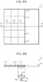
- FIG. 8A is a plan view showing a configuration of an antenna device 3 according to the third embodiment.
- FIG. 8B is a cross-sectional view of the antenna device 3 whose cross section is a plane cut along a dotted line ⁇ 4 of FIG. 8A .
- the antenna device 3 according to the third embodiment differs from the antenna device 1 according to the first embodiment in that the antenna device 3 includes a parabolic antenna 300, which is an aperture antenna, instead of a planar antenna, and mutual arrangement of a first part 311, a second part 312, and a third part 313 of the radome 310 is different from each other.
- the second part 312 can be integrally formed so as to surround the first part 231.
- the third part 313 can be integrally formed so as to surround the second part 312.
- the parabolic antenna 300 includes a primary radiator 301, a reflection mirror 302 facing the primary radiator 301, and a base 303 connected to the reflection mirror 302.
- the primary radiator 301 radiates a beam to the reflection mirror 302, and the reflection mirror 302 reflects the beam radiated by the primary radiator 301 toward the radome 310.
- the configuration including the primary radiator 301 and the reflection mirror 302 can change the scanning angle of the emitted beam by rotating around the contact point with the base 303.
- the third part 313 of the radome 310 is adjacent to one end I of the second part 312, and the first part 311 is adjacent to the other end J of the second part 312.
- the first part 311 of the radome 310 has a surface S 3 facing an aperture plane S 4 of the parabolic antenna 300 when the aperture plane S 4 of the parabolic antenna 300 is directed toward the first part 311 as shown in FIG. 8B , and the size of the surface S 3 of the first part 311 is equivalent to the size of the aperture plane S 4 of the parabolic antenna 300.
- FIG. 9 is a cross-sectional view showing a configuration when the aperture plane S 4 of the parabolic antenna 300 is directed toward the third part 313.
- the first part 311 is located in the direction of the scanning angle of 0 degrees with respect to the parabolic antenna 300
- the second part 312 is located in the direction of the first scanning angle with respect to the parabolic antenna 300
- the third part 313 is located in the direction of a second scanning angle ⁇ 7 with respect to the parabolic antenna 300.
- the first scanning angle is a scanning angle between the second scanning angle ⁇ 7 and the scanning angle of 0 degrees.
- the end of the third part 313 adjacent to one end I of the second part 312 is located in a direction of a scanning angle wider than the second scanning angle ⁇ 7 with respect to one end K of the aperture plane S 4 of the parabolic antenna 300.
- the beam transmission characteristics of the first part 311, the second part 312, and the third part 313 of the radome 310 will be described below.
- the first part 311 of the radome 310 has a beam transmission characteristic corresponding to a scanning angle of 0 degrees of the beam emitted by the parabolic antenna 300 with the emission direction directed toward the first part 311.
- the second part 312 of the radome 310 has a beam transmission characteristic corresponding to the first scanning angle of the beam emitted by the parabolic antenna 300 with the emission direction directed toward the second part 312.
- the third part 313 of the radome 310 has a beam transmission characteristic corresponding to the second scanning angle ⁇ 7 of the beam emitted by the parabolic antenna 300 with the emission direction directed toward the third part 313.
- the first scanning angle is a scanning angle between the second scanning angle ⁇ 7 and the scanning angle of 0 degrees.
- each of the first part 311, the second part 312, and the third part 313 is composed of one or more layers.
- the first part 311 and the second part 312 differ in at least one or more of the number of layers, the material of the layer, and the thickness of each layer when the one or more layers are a plurality of layers, and thus differ in the beam transmission characteristic.
- the first part 311 and the third part 313 differ in at least one or more of the number of layers, the material of the layer, and the thickness of each layer when the one or more layers are a plurality of layers, and thus differ in the beam transmission characteristic.
- the second part 312 and the third part 313 differ in at least one or more of the number of layers, the material of the layer, and the thickness of each layer when the one or more layers are a plurality of layers, and thus differ in the beam transmission characteristic.
- FIG. 10A is a plan view showing a configuration of an antenna device 30 according to the modified example of the third embodiment.
- FIG. 10B is a cross-sectional view of the antenna device 30 whose cross section is a plane cut along a dotted line ⁇ 5 of FIG. 10A .
- a radome 320 in the antenna device 30, a radome 320 further includes, in addition to a first part 321, a second part 322, and a third part 323, a fourth part 324 and a fifth part 325 each having a surface flush with each surface of these parts.
- the parabolic antenna 300 has the aperture plane S 4 directed toward the fifth part 325.
- the radome 320 includes the fourth part 324 adjacent to the end L of the first part 321, and includes the fifth part 325 adjacent to the end M of the fourth part 324.
- the end L of the first part 321 is the end of the first part 321 opposite to the end adjacent to the second part 322
- the end M of the fourth part 324 is the end of the fourth part 324 opposite to the end adjacent to the first part 321.
- the fourth part 324 can be integrally formed with the second part 322 so as to surround the first part 321.
- the fifth part 325 can be integrally formed with the third part 323 so as to surround the second part 322 and the fourth part 324.
- the fourth part 324 is located in the direction of the third scanning angle with respect to the parabolic antenna 300, and the fifth part 325 is located in the direction of the fourth scanning angle ⁇ 8 with respect to the parabolic antenna 300.
- the third scanning angle is a scanning angle between the fourth scanning angle ⁇ 8 and the scanning angle of 0 degrees. More specifically about mutual arrangement of the fourth part 324 and the fifth part 325, the end of the fifth part adjacent to one end M of the fourth part is located in a direction of a scanning angle wider than the fourth scanning angle ⁇ 8 with respect to the other end N of the aperture plane S 4 of the parabolic antenna 300.
- the beam transmission characteristics of the fourth part 324 and the fifth part 325 of the radome 320 will be described below.
- the fourth part 324 of the radome 320 has a beam transmission characteristic corresponding to the third scanning angle of the beam emitted by the parabolic antenna 300 with the emission direction directed toward the fourth part 324.
- the fifth part 325 of the radome 320 has a beam transmission characteristic corresponding to the fourth scanning angle ⁇ 8 of the beam emitted by the parabolic antenna 300 with the emission direction directed toward the fifth part 325.
- the third scanning angle is a scanning angle between the fourth scanning angle ⁇ 8 and the scanning angle of 0 degrees.
- the antenna is a parabolic antenna 300 as an aperture antenna
- the third part 313 is adjacent to one end I of the second part 312
- the first part 311 is adjacent to the other end J of the second part 312.
- the third part 313 covers the aperture antenna, and in a region adjacent to the other end J of the second part 312, the first part 311 covers the aperture antenna.
- each of the first part 311, the second part 312, and the third part 313 is composed of one or more layers
- the first part 311 and the second part 312 differ in at least one or more of the number of layers, the material of the layer, and the thickness of each layer when the one or more layers are a plurality of layers and thus differ in the beam transmission characteristic
- the first part 311 and the third part 313 differ in at least one or more of the number of layers, the material of the layer, and the thickness of each layer when the one or more layers are a plurality of layers and thus differ in the beam transmission characteristic
- the second part 312 and the third part 313 differ in at least one or more of the number of layers, the material of the layer, and the thickness of each layer when the one or more layers are a plurality of layers and thus differ in the beam transmission characteristic.
- At least one or more of the number of layers, the material of the layer, and the thickness of each layer when the one or more layers are a plurality of layers are made different from each other, and thereby it is possible to suppress the attenuation of the beam intensity depending on the scanning angle of the beam in the radome without providing a step on the surface of the radome.
- the first part 311 is located in the direction of a scanning angle of 0 degrees with respect to the aperture antenna
- the second part 312 is located in the direction of the first scanning angle between the second scanning angle and the scanning angle of 0 degrees with respect to the aperture antenna
- the third part 313 is located in the direction of the second scanning angle ⁇ 7 with respect to the aperture antenna.
- the first part 311 is disposed so as to suppress the attenuation of the beam intensity when the aperture antenna emits a beam in the direction of a scanning angle of 0 degrees.
- the second part 312 is disposed so as to suppress the attenuation of the beam intensity when the aperture antenna emits a beam in the direction of the first scanning angle.
- the third part 313 is disposed so as to suppress the attenuation of the beam intensity when the aperture antenna emits a beam in the direction of the second scanning angle ⁇ 7 . This makes it possible to suppress the attenuation of the beam intensity depending on the scanning angle of the beam in the radome.
- the first part 311 has a surface facing the aperture plane S 4 when the aperture plane S 4 of the aperture antenna is directed toward the first part 311, and the size of the surface of the first part 311 is equivalent to the size of the aperture plane S 4 of the aperture antenna.
- the first part 311 covers the aperture antenna in a region having a size equivalent to the size of the aperture plane S 4 of the aperture antenna. This makes it possible to suppress the attenuation of the beam intensity of the beam emitted toward the region while protecting the aperture antenna from the external environment such as wind, rain, or dust from the region.
- the fourth embodiment will be described below by referring to the drawings.
- the configuration in which the antenna covered by the radome is a parabolic antenna as an aperture antenna has been described.
- a configuration in which the antenna covered by the radome is a horn antenna as an aperture antenna will be described.
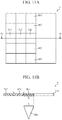
- FIG. 11A is a plan view showing a configuration of an antenna device 4 according to the fourth embodiment.
- FIG. 11B is a cross-sectional view of the antenna device 4 whose cross section is a plane cut along a dotted line ⁇ 6 of FIG. 11B .
- the antenna device 4 according to the fourth embodiment differs from the antenna device 3 according to the third embodiment in that the antenna device 4 includes a horn antenna 400 as an aperture antenna.
- the horn antenna 400 emits a beam from an aperture plane S 5 toward a radome 410.
- a third part 413 of the radome 410 is adjacent to one end O of a second part 412, and a first part 411 is adjacent to the other end P of the second part 412.
- the first part 411 of the radome 410 has a surface S 6 facing the aperture plane S 5 of the horn antenna 400 when the aperture plane S 5 of the horn antenna 400 is directed toward the first part 411 as shown in FIG. 11B , and the size of the surface S 6 of the first part 411 is equivalent to the size of the aperture plane S 5 of the horn antenna 400.
- FIG. 12 is a cross-sectional view showing a configuration when the aperture plane S 5 of the horn antenna 400 is directed toward the third part 413.
- the first part 411 is located in the direction of a scanning angle of 0 degrees with respect to the horn antenna 400
- the second part 412 is located in the direction of the first scanning angle with respect to the horn antenna 400
- the third part 413 is located in the direction of a second scanning angle ⁇ 9 with respect to the horn antenna 400.
- the first scanning angle is a scanning angle between the second scanning angle ⁇ 9 and the scanning angle of 0 degrees.
- the end of the third part 413 adjacent to one end O of the second part 412 is located in the direction of a scanning angle wider than the second scanning angle ⁇ 9 with respect to one end Q of the aperture plane S 5 of the horn antenna 400.
- the beam transmission characteristics of the first part 411, the second part 412, and the third part 413 of the radome 410 will be described below.
- the first part 411 of the radome 410 has a beam transmission characteristic corresponding to a scanning angle of 0 degrees of the beam emitted by the horn antenna 400 with the emission direction directed toward the first part 411.
- the second part 412 of the radome 410 has a beam transmission characteristic corresponding to the first scanning angle of the beam emitted by the horn antenna 400 with the emission direction directed toward the second part 412.
- the third part 413 of the radome 410 has a beam transmission characteristic corresponding to the second scanning angle ⁇ 9 of the beam emitted by the horn antenna 400 with the emission direction directed toward the third part 413.
- the first scanning angle is a scanning angle between the second scanning angle ⁇ 9 and the scanning angle of 0 degrees.
- each of the first part 411, the second part 412, and the third part 413 is composed of one or more layers.
- the first part 411 and the second part 412 differ in at least one or more of the number of layers, the material of the layer, and the thickness of each layer when the one or more layers are a plurality of layers, and thus differ in the beam transmission characteristic.
- the first part 411 and the third part 413 differ in at least one or more of the number of layers, the material of the layer, and the thickness of each layer when the one or more layers are a plurality of layers, and thus differ in the beam transmission characteristic.
- the second part 412 and the third part 413 differ in at least one or more of the number of layers, the material of the layer, and the thickness of each layer when the one or more layers are a plurality of layers, and thus differ in the beam transmission characteristic.
- FIG. 13A is a plan view showing a configuration of an antenna device 40 according to the modified example of the fourth embodiment.
- FIG. 13B is a cross-sectional view of the antenna device 40 whose cross section is a plane cut along a dotted line ⁇ 7 of FIG. 13A .
- the radome 420 in the antenna device 40, further includes, in addition to a first part 421, a second part 422, and a third part 423, a fourth part 424 and a fifth part 425 each having a surface flush with each surface of these parts.
- the horn antenna 400 has the aperture plane S 5 directed to the fifth part 425.
- the radome 420 includes the fourth part 424 adjacent to the end R of the first part 421, and includes the fifth part 425 adjacent to the end S of the fourth part 424.
- the end R of the first part 421 is the end of the first part 421 opposite to the end adjacent to the second part 422
- the end S of the fourth part 424 is the end of the fourth part 424 opposite to the end adjacent to the first part 421.
- the fourth part 424 is located in the direction of the third scanning angle with respect to the horn antenna 400, and the fifth part 425 is located in the direction of the fourth scanning angle ⁇ 10 with respect to the horn antenna 400.
- the third scanning angle is a scanning angle between the fourth scanning angle ⁇ 10 and the scanning angle of 0 degrees. More specifically about mutual arrangement of the fourth part 424 and the fifth part 425, the end of the fifth part adjacent to one end S of the fourth part is located in the direction of a scanning angle wider than the fourth scanning angle ⁇ 10 with respect to the other end T of the aperture plane S 5 of the horn antenna 400.
- the beam transmission characteristics of the fourth part 424 and the fifth part 425 of the radome 420 will be described below.
- the fourth part 424 of the radome 420 has a beam transmission characteristic corresponding to the third scanning angle of the beam emitted by the horn antenna 400 with the emission direction directed toward the fourth part 424.
- the fifth part 425 of the radome 420 has a beam transmission characteristic corresponding to the fourth scanning angle ⁇ 10 of the beam emitted by the horn antenna 400 with the emission direction directed toward the fifth part 425.
- the third scanning angle is a scanning angle between the fourth scanning angle ⁇ 10 and the scanning angle of 0 degrees.
- the fourth embodiment shows the configuration in which the aperture antenna covered by the radome 410 is the horn antenna 400. Even with such a configuration, the same effect as that of the antenna device 3 according to the third embodiment is obtained.
- the antenna device can suppress the attenuation of the beam intensity depending on the scanning angle of the beam emitted by the antenna in the radome without providing a step on the surface of the radome in the antenna device provided with the radome that covers the antenna, and therefore it can be used for antenna devices equipped with a radome that covers the antenna.
- antenna device 100: planar antenna, 101: a plurality of antenna elements, 102: dielectric substrate, 110, 120, 130, 140, 150, 210, 220, 230, 310, 320, 410, 420: radome, 111, 121, 131, 141, 151, 211, 221, 231, 311, 321, 411, 421: first part, 112, 122, 132, 142, 152, 212, 222, 232, 312, 322, 412, 422: second part, 113, 123, 133, 143, 153, 213, 223, 233, 313, 323, 413, 423: third part, 214, 224, 234, 324, 424: fourth part, 215, 225, 235, 325, 425: fifth part, 236: sixth part, 237: seventh part, 300: parabolic antenna, 301: primary radiator, 302: reflection mirror, 303: base, 400: horn antenna.
Landscapes
- Details Of Aerials (AREA)
- Variable-Direction Aerials And Aerial Arrays (AREA)
- Aerials With Secondary Devices (AREA)
- Waveguide Aerials (AREA)
Abstract

Description
- The present invention relates to an antenna device including a radome covering the antenna.
- The antenna may be equipped with a radome that covers a beam emitting surface to protect it from the external environment such as wind, rain or dust. However, in a general radome with a uniform thickness, it is known that since the beam transmission characteristic changes corresponding to an incident angle of a beam emitted by the antenna toward the radome, the attenuation of a beam intensity of a beam emitted by the antenna at a scanning angle other than a specific scanning angle is larger than that of a beam emitted at the specific scanning angle. Therefore, it is necessary to suppress the attenuation of the beam intensity depending on the scanning angle of the beam in the radome.
- There is a technique for changing the thickness of the radome in the middle in order to suppress the attenuation of the beam intensity depending on the scanning angle of the beam in the radome. For example, the antenna device described in
Patent Literature 1 has a structure in which the thickness of the radome is 1/2 wavelength or 1/4 wavelength in a narrower-angle direction than a predetermined direction when viewed from the antenna, and the thickness of the radome in a wider-angle direction than a predetermined direction when viewed from the antenna is thicker than the thickness of the radome in the narrow-angle direction. Therefore, in the antenna device, one surface of the radome has a step. - Patent Literature 1:
JP 2018-137563A - When a step is provided on the surface of the radome, it is strongly affected by the external environment such as air resistance or thermal deformation depending on the intended use of the antenna device. Further, limiting the thickness of the radome in the narrower-angle direction than the predetermined direction when viewed from the antenna is a constraint on the design of the antenna device. Further, if the thickness of the radome in the narrow-angle direction is set to the thickness of 1/2 wavelength or 1/4 wavelength of a high frequency band such as millimeter wave, there is a problem that the mechanical strength of the radome is weakened.
- The present invention has been made to solve the above-mentioned problems, and has an object to suppress the attenuation of the beam intensity depending on the scanning angle of the beam in the radome without providing a step on the surface of the radome in an antenna device provided with the radome covering the antenna.
- The antenna device according to the present invention includes an antenna and a radome that covers the antenna, in which the radome includes a first part, a second part and a third part each with a surface which is flush to each other, the first part has a beam transmission characteristic corresponding to a scanning angle of 0 degrees of a beam emitted by the antenna with an emission direction directed toward the first part, the second part has a beam transmission characteristic corresponding to a first scanning angle of a beam emitted by the antenna with an emission direction directed toward the second part, and the third part has a beam transmission characteristic corresponding to a second scanning angle of a beam emitted by the antenna with an emission direction directed toward the third part.
- In an antenna device provided with a radome covering the antenna, it is possible to suppress the attenuation of the beam intensity depending on the scanning angle of the beam emitted by the antenna in the radome without providing a step on the surface of the radome.
-
-
FIG. 1A is a plan view showing a configuration of an antenna device according to a first embodiment.FIG. 1B is a cross-sectional view showing the configuration of the antenna device according to the first embodiment. -
FIG. 2A is a cross-sectional view of a radome according to a first specific example of the first embodiment.FIG. 2B is a cross-sectional view of a radome according to a second specific example of the first embodiment.FIG. 2C is a cross-sectional view of a radome according to a third specific example of the first embodiment.FIG. 2D is a cross-sectional view of a radome according to a modified example of the first embodiment. -
FIG. 3A is a plan view showing a configuration of an antenna device according to a second embodiment.FIG. 3B is a cross-sectional view showing a configuration of the antenna device according to the second embodiment. -
FIG. 4 is a cross-sectional view showing a configuration of an antenna device according to a specific example of the second embodiment. -
FIG. 5 is a graph showing a layer structure of a radome according to a specific example of the second embodiment. -
FIG. 6 is a graph showing a beam transmission characteristic of a radome according to a specific example of the second embodiment and a beam transmission characteristic of a radome having a beam transmission characteristic corresponding to a specific scanning angle. -
FIG. 7A is a plan view showing a configuration of an antenna device according to a modified example of the second embodiment.FIG. 7B is a cross-sectional view showing the configuration of the antenna device according to the modified example of the second embodiment. -
FIG. 8A is a plan view showing a configuration of an antenna device according to a third embodiment.FIG. 8B is a cross-sectional view showing the configuration of the antenna device according to the third embodiment. -
FIG. 9 is a cross-sectional view showing a configuration of a parabolic antenna when an aperture plane is directed to a third part. -
FIG. 10A is a plan view showing a configuration of an antenna device according to a modified example of the third embodiment.FIG. 10B is a cross-sectional view showing the configuration of the antenna device according to the modified example of the third embodiment. -
FIG. 11A is a plan view showing a configuration of an antenna device according to a fourth embodiment.FIG. 11B is a cross-sectional view showing the configuration of the antenna device according to the fourth embodiment. -
FIG. 12 is a cross-sectional view showing a configuration of a horn antenna when an aperture plane is directed to a third part. -
FIG. 13A is a plan view showing a configuration of an antenna device according to a modified example of the fourth embodiment.FIG. 13B is a cross-sectional view showing the configuration of the antenna device according to the modified example of the fourth embodiment. - Hereinafter, in order to explain this invention in more detail, embodiments for carrying out the present invention will be described by referring to the accompanying drawings.
-
FIG. 1A is a plan view showing the configuration of anantenna device 1 according to a first embodiment.FIG. 1B is a cross-sectional view of theantenna device 1 whose cross section is a plane cut along a dotted line α1 ofFIG. 1A . As shown inFIGS. 1A and 1B , theantenna device 1 includes aplanar antenna 100 and aradome 110 that covers the planar antenna. - The
radome 110 includes afirst part 111, asecond part 112, and a third part 113which are flush with each other. More specifically, thesecond part 112 is adjacent to one end A of the first part and thethird part 113 is adjacent to the other end B of the first part. Note that, thesecond part 112 and thethird part 113 can be integrally formed together with each part of theradome 110 other than thefirst part 111 so as to surround thefirst part 111. - The
planar antenna 100 includes adielectric substrate 102 and a plurality ofantenna elements 101 installed side by side on thedielectric substrate 102. Theplanar antenna 100 emits a beam toward theradome 110 from a beam emitting surface composed of the surfaces of the plurality ofantenna elements 101. Theplanar antenna 100 can change the emission direction of the beam by changing the scanning angle of the beam by using a plurality ofantenna elements 101. Note that, in the present embodiment, the configuration in which theplanar antenna 100 is used as the antenna covered by theradome 110 will be described, but the antenna covered by theradome 110 may be an antenna capable of changing the beam emission direction, and is not limited to the configuration. - As a detailed arrangement of the
first part 111, thesecond part 112, and thethird part 113 of theradome 110 and theplanar antenna 100, thefirst part 111 is located in a direction of a scanning angle of 0 degrees with respect to theplanar antenna 100, thesecond part 112 is located in a direction of a first scanning angle θ1 with respect to theplanar antenna 100, and thethird part 113 is located in a direction of a second scanning angle θ2 with respect to theplanar antenna 100. More specifically, one end A of thefirst part 111 is located in a direction of a scanning angle narrower than the first scanning angle θ1 with respect to one end C of the beam emitting surface composed of the surfaces of the plurality ofantenna elements 101 included in theplanar antenna 100, and the other end B of thefirst part 111 is located in a direction of a scanning angle narrower than the second scanning angle θ2 with respect to the other end D of theplanar antenna 100. Note that, in the specification of the present application, the scanning angle of the beam emitted by theplanar antenna 100 is a scanning angle using a line orthogonal to a beam emitting surface of theplanar antenna 100 and the surface of thefirst part 111 facing the beam emitting surface as a reference line, and it is assumed that the scanning angle on thesecond part 112 side is a positive scanning angle, and the scanning angle on thethird part 113 side is a negative scanning angle. - In the present embodiment, as described above, the size of the
first part 111 is defined by the first scanning angle θ1 and the second scanning angle θ2, but the size of thefirst part 111 may be defined by the size of the beam emitting surface of theplanar antenna 100. In that case, for example, thefirst part 111 has a surface facing the beam emitting surface of theplanar antenna 100, and the size of the surface of thefirst part 111 is equivalent to or larger than the size of the beam emitting surface of the planar antenna. - Hereinafter, the beam transmission characteristics of the
first part 111, thesecond part 112, and the third part of theradome 110 will be described. Thefirst part 111 of theradome 110 has a beam transmission characteristic corresponding to a scanning angle of 0 degrees of a beam emitted by theplanar antenna 100 with an emission direction directed toward thefirst part 111. Note that, the "beam transmission characteristic" means the ease of transmission of the beam incident from a specific direction in theradome 110. Further, "thefirst part 111 has a beam transmission characteristic corresponding to a scanning angle of 0 degrees" means that thefirst part 111 has a characteristic of more easily transmitting a beam when theplanar antenna 100 emits the beam at a scanning angle of 0 degrees than when theplanar antenna 100 emits a beam at a scanning angle other than 0 degrees. - The
second part 112 of theradome 110 has a beam transmission characteristic corresponding to the first scanning angle θ1 of the beam emitted by theplanar antenna 100 with the emission direction directed toward thesecond part 112. Thethird part 113 of theradome 110 has a beam transmission characteristic corresponding to the second scanning angle θ2 of the beam emitted by theplanar antenna 100 with the emission direction directed toward thethird part 113. - More specifically about the beam transmission characteristics of the
first part 111, thesecond part 112, and thethird part 113, each of thefirst part 111, thesecond part 112, and thethird part 113 is composed of one or more layers. Thefirst part 111 and thesecond part 112 differ in at least one or more of the number of layers, the material of the layer, and the thickness of each layer when the one or more layers are a plurality of layers, and thus differ in the beam transmission characteristic. Thefirst part 111 and thethird part 113 differ in at least one or more of the number of layers, the material of the layer, and the thickness of each layer when the one or more layers are a plurality of layers, and thus differ in the beam transmission characteristic. An example of the material of the layer is a dielectric or the like. Note that, the number of layers, the material of the layer, and the thickness of each layer when the one or more layers are a plurality of layers can be the same in thesecond part 112 and thethird part 113. In that case, the beam transmission characteristic of thesecond part 112 and the beam transmission characteristic of thethird part 113 are the same. - Next, a specific example of the
radome 110 according to the first embodiment will be described by referring to the drawings.FIG. 2A is a cross-sectional view of aradome 120 according to a first specific example of the first embodiment. As shown inFIG. 2A , each of afirst part 121, asecond part 122, and athird part 123 of theradome 120 is composed of one layer. In the first specific example, thefirst part 111 and thesecond part 112 differ in the material of the layer, and thus differ in the beam transmission characteristic. Further, similarly, thefirst part 111 and thethird part 113 differ in the material of the layer, and thus differ in the beam transmission characteristic. -
FIG. 2B is a cross-sectional view of aradome 130 according to a second specific example of the first embodiment. As shown inFIG. 2B , each of afirst part 131, asecond part 132, and athird part 133 of theradome 130 is composed of three layers. In the second specific example, thefirst part 111 and thesecond part 112 differ in the material of any one or more layers of the three layers, and thus differ in the beam transmission characteristic. Further, similarly, thefirst part 111 and thethird part 113 differ in the material of any one or more layers of the three layers, and thus differ in the beam transmission characteristic. -
FIG. 2C is a cross-sectional view of aradome 140 according to a third specific example of the first embodiment. As shown inFIG. 2C , afirst part 141 of theradome 140 is composed of three layers, and each of asecond part 142 and athird part 143 is composed of two layers. In the third specific example, thefirst part 141 and thesecond part 142 differ in the material of layer, the number of layers, and the thickness of each layer, and thus differ in the beam transmission characteristic. Further, similarly, thefirst part 141 and thethird part 143 differ in the material of layer, the number of layers, and the thickness of each layer, and thus differ in the beam transmission characteristic. -
FIG. 2D is a cross-sectional view of aradome 150 according to a modified example of the first embodiment. As shown inFIG. 2D , each of afirst part 151, asecond part 152, and athird part 153 of theradome 150 is composed of one curved layer. In the drawing of each of the above specific examples, a planar radome is shown, but as in theradome 150 ofFIG. 2D , the radome covering theplanar antenna 100 may be curved. Also, the curvature of the curve of such a radome can be any value. - As described above, the
antenna device 1 according to the first embodiment includes aplanar antenna 100 as an antenna and a radome covering theplanar antenna 100, and theradome 110 includes afirst part 111, asecond part 112, and athird part 113 each with a surface which is flush to each other, thefirst part 111 has a beam transmission characteristic corresponding to a scanning angle of 0 degrees of the beam emitted by theplanar antenna 100 with an emission direction directed toward thefirst part 111, thesecond part 112 has a beam transmission characteristic corresponding to a first scanning angle θ1 of the beam emitted by theplanar antenna 100 with the emission direction directed toward thesecond part 112, and thethird part 113 has a beam transmission characteristic corresponding to a second scanning angle θ2 of the beam emitted by theplanar antenna 100 with the emission direction directed toward thethird part 113. - According to the above configuration, the surfaces of the
first part 111, thesecond part 112, and thethird part 113 are flush with each other. Further, thefirst part 111 suppresses the attenuation of the beam intensity when theplanar antenna 100 emits a beam at a scanning angle of 0 degrees. Thesecond part 112 suppresses the attenuation of the beam intensity when theplanar antenna 100 emits a beam at the first scanning angle. Thethird part 113 suppresses the attenuation of the beam intensity when theplanar antenna 100 emits a beam at the second scanning angle. This makes it possible to suppress the attenuation of the beam intensity depending on the scanning angle of the beam in the radome without providing a step on the surface of the radome. - Further, in the
antenna device 1 according to the first embodiment, each of thefirst part 111, thesecond part 112, and thethird part 113 is composed of one or more layers, and thefirst part 111 and thesecond part 112 differ in at least one or more of the number of layers, the material of the layer, and the thickness of each layer when the one or more layers are a plurality of layers, and thus differ in the beam transmission characteristic, and thefirst part 111 and thethird part 113 differ in at least one or more of the number of layers, the material of the layer, and the thickness of each layer when the one or more layers are a plurality of layers, and thus differ in the beam transmission characteristic. - According to the above configuration, at least one or more of the number of layers, the material of the layer, and the thickness of each layer when the one or more layers are a plurality of layers are made different from each other, and thereby it is possible to suppress the attenuation of the beam intensity depending on the scanning angle of the beam in the radome without providing a step on the surface of the radome.
- Further, in the
antenna device 1 according to the first embodiment, the antenna is aplanar antenna 100, thesecond part 112 is adjacent to one end A of thefirst part 111, and thethird part 113 is adjacent to the other end B of thefirst part 111. - According to the above configuration, in a region adjacent to one end A of the
first part 111, thesecond part 112 covers theplanar antenna 100, and in a region adj acent to the other end B of thefirst part 111, thethird part 113 covers theplanar antenna 100. This makes it possible to suppress the attenuation of the beam intensity of the beam emitted toward these regions while protecting theplanar antenna 100 from the external environment such as wind, rain or dust from the region adjacent to one end A of thefirst part 111 and the region adj acent to the other end B of thefirst part 111. - Further, in the
antenna device 1 according to the first embodiment, thefirst part 111 is located in the direction of a scanning angle of 0 degrees with respect to theplanar antenna 100, thesecond part 112 is located in the direction of the first scanning angle θ1 with respect to theplanar antenna 100, and thethird part 113 is located in the direction of the second scanning angle θ2 with respect to theplanar antenna 100. - According to the above configuration, the
first part 111 is disposed so as to suppress the attenuation of the beam intensity when theplanar antenna 100 emits a beam in the direction of a scanning angle of 0 degrees. Thesecond part 112 is disposed so as to suppress the attenuation of the beam intensity when theplanar antenna 100 emits a beam in the direction of the first scanning angle. Thethird part 113 is disposed so as to suppress the attenuation of the beam intensity when theplanar antenna 100 emits a beam in the direction of the second scanning angle. This makes it possible to suppress the attenuation of the beam intensity depending on the scanning angle of the beam in the radome. - The second embodiment will be described below by referring to the drawings. Note that, the same reference numerals are given to the configurations having the same functions as those described in the first embodiment, and the description thereof will be omitted.
- In the first embodiment, the configuration in which the
radome 110 includes three parts, thefirst part 111, thesecond part 112, and thethird part 113, has been described. In the second embodiment, a configuration in which aradome 210 further includes one or more parts each having a surface flush with each surface of afirst part 211, asecond part 212, and athird part 213 will be described. -
FIG. 3A is a plan view showing a configuration of anantenna device 2 according to the second embodiment.FIG. 3B is a cross-sectional view of theantenna device 2 whose cross section is a plane cut along a dotted line α2 ofFIG. 3A . As shown inFIGS. 3A and 3B , theantenna device 2 according to the second embodiment differs from theantenna device 1 according to the first embodiment in that theradome 210 further includes afourth part 214 and afifth part 215 in addition to thefirst part 211, thesecond part 212, and thethird part 213, and the size of a surface S1 of thefirst part 211 facing the beam emitting surface of theplanar antenna 100 is equivalent to the size of a beam emitting surface S2 of theplanar antenna 100. Note that, thefourth part 214 and thefifth part 215 can be integrally formed so as to surround thefirst part 211, thesecond part 212, and thethird part 213. - The arrangement of the
fourth part 214 and thefifth part 215 will be described below. Theradome 210 includes thefourth part 214 adjacent to the end E of thesecond part 212 and thefifth part 215 adjacent to the end F of thethird part 213. Note that, the end E of thesecond part 212 is the end of thesecond part 212 opposite to the end adjacent to thefirst part 211, and the end F of thethird part 213 is the end of thethird part 213 opposite to the end adjacent to thefirst part 211. Thefourth part 214 is located in a direction of a third scanning angle θ3 with respect to theplanar antenna 100, and thefifth part 215 is located in a direction of a fourth scanning angle θ4 with respect to theplanar antenna 100. More specifically, the end of thefourth part 214 adjacent to the end E of thesecond part 212 is located in a direction of a scanning angle wider than the third scanning angle θ3 with respect to one end C of a beam emitting surface composed of the surfaces of a plurality ofantenna elements 101 included in theplanar antenna 100. The end of thefifth part 215 adjacent to the end F of thethird part 213 is located in a direction of a scanning angle wider than the fourth scanning angle θ4 with respect to the other end D of the beam emitting surface composed of the surfaces of a plurality ofantenna elements 101 included in theplanar antenna 100. Further, thesecond part 212 is located between thefirst part 211 and thefourth part 214 defined as described above, and thethird part 213 is located between thefirst part 211 and thefifth part 215 defined as described above. - Next, the beam transmission characteristics of the
first part 211, thesecond part 212, thethird part 213, thefourth part 214, and thefifth part 215 included in theradome 210 will be described. Thefirst part 211 of theradome 210 has a beam transmission characteristic corresponding to a scanning angle of 0 degrees of the beam emitted by theplanar antenna 100 with the emission direction directed toward thefirst part 211. Thefourth part 214 of theradome 210 has a beam transmission characteristic corresponding to the third scanning angle θ3 of the beam emitted by theplanar antenna 100 with the emission direction directed toward thefourth part 214. Thefifth part 215 of theradome 210 has a beam transmission characteristic corresponding to the fourth scanning angle θ4 of the beam emitted by theplanar antenna 100 with the emission direction directed toward thefifth part 215. Note that, thesecond part 212 of theradome 210 has a beam transmission characteristic corresponding to the first scanning angle between the scanning angle of 0 degrees and the third scanning angle θ3. Thefifth part 215 of theradome 210 has a beam transmission characteristic corresponding to the second scanning angle between the scanning angle of 0 degrees and the fourth scanning angle θ4. - Next, a specific example of the
antenna device 2 according to the second embodiment will be described by referring to the drawings.FIG. 4 is a cross-sectional view showing a configuration of anantenna device 20 according to a specific example of the second embodiment. In theantenna device 20, the end of afourth part 224 adjacent to the end E of asecond part 222 is located in a direction of a scanning angle narrower than a scanning angle of 70 degrees with respect to the other end D of the beam emitting surface composed of the surfaces of a plurality ofantenna elements 101 included in theplanar antenna 100. The end of afifth part 225 adjacent to the end F of athird part 223 is located in a direction of a scanning angle narrower than a scanning angle of -70 degrees with respect to one end C of a beam emitting surface composed of the surfaces of a plurality ofantenna elements 101 included in theplanar antenna 100. Further, theplanar antenna 100 of theantenna device 20 includes a plurality of 12 × 12antenna elements 101. - The beam transmission characteristics of the
first part 221, thesecond part 222, thethird part 223, thefourth part 224, and thefifth part 225 included in theradome 220 will be described below. Thefirst part 221 of theradome 220 has a beam transmission characteristic corresponding to a scanning angle of 0 degrees of the beam emitted by theplanar antenna 100 with the emission direction directed toward thefirst part 221. Thesecond part 222 of theradome 220 has a beam transmission characteristic corresponding to a first scanning angle of 35 degrees of the beam emitted by theplanar antenna 100 with the emission direction directed toward thesecond part 222. Thethird part 223 of theradome 220 has a beam transmission characteristic corresponding to a second scanning angle of -35 degrees of the beam emitted by theplanar antenna 100 with the emission direction directed toward thethird part 223. - The
fourth part 224 of theradome 220 has a beam transmission characteristic corresponding to a third scanning angle of 70 degrees of the beam emitted by theplanar antenna 100 with the emission direction directed toward thefourth part 224. Thefifth part 225 of theradome 220 has a beam transmission characteristic corresponding to a fourth scanning angle of -70 degrees of the beam emitted by theplanar antenna 100 with the emission direction directed toward thefifth part 225. -
FIG. 5 is a graph showing a layer structure of theradome 220 according to a specific example of the second embodiment. The bar graph on the left side ofFIG. 5 shows each layer of thefirst part 221, the bar graph in the middle ofFIG. 5 shows each layer of thesecond part 222 and thethird part 223, and the bar graph on the right side ofFIG. 5 shows each layer of thefourth part 224 and thefifth part 225. The vertical axis ofFIG. 5 shows the thickness of the layer in each part. - As shown in
FIG. 5 , thefirst part 221 is composed of a PTFE (polytetrafluoroethylene) layer having a thickness of 1.4 mm, a QFRP (Quartz Fiber Reinforced Plastic) layer having a thickness of 1.0 mm, a PTFE layer having a thickness of 1.2 mm, and a form layer having a thickness of 3.1 mm. Note that, the form layer is a base layer for depositing each of the above layers, and is formed of a dielectric different from PTFE and QFRP. In addition, each of these layers is bonded with an adhesive shown as bond inFIG. 5 . Thefirst part 221 is composed of a plurality of layers of the above-mentioned material and thickness, and thus has a beam transmission characteristic corresponding to a scanning angle of 0 degrees of the beam emitted by theplanar antenna 100 toward thefirst part 221. - As shown in
FIG. 5 , each of thesecond part 222 and thethird part 223 is composed of a PTFE layer having a thickness of 1.5 mm, a QFRP layer having a thickness of 1.3 mm, a PTFE layer having a thickness of 1.4 mm, and a form layer having a thickness of 2.6 mm. Note that each of these layers is bonded with an adhesive. Thesecond part 222 is composed of a plurality of layers of the above-mentioned material and thickness, and thus has a beam transmission characteristic corresponding to a scanning angle of 35 degrees of the beam emitted by theplanar antenna 100 toward thesecond part 222. Thethird part 223 is composed of a plurality of layers of the above-mentioned material and thickness, and thus has a beam transmission characteristic corresponding to a scanning angle of -35 degrees of the beam emitted by theplanar antenna 100 toward thethird part 223. - As shown in
FIG. 5 , each of thefourth part 224 and thefifth part 225 is composed of a PTFE layer having a thickness of 1.6 mm, a QFRP layer having a thickness of 1.5 mm, a PTFE layer having a thickness of 1.5 mm, and a form layer having a thickness of 2.1 mm. Note that each of these layers is bonded with an adhesive. Thefourth part 224 is composed of a plurality of layers of the above-mentioned material and thickness, and thus has a beam transmission characteristic corresponding to a scanning angle of 70 degrees of the beam emitted by theplanar antenna 100 toward thefourth part 224. Thefifth part 225 is composed of a plurality of layers of the above-mentioned material and thickness, and thus has a beam transmission characteristic corresponding to a scanning angle of -70 degrees of the beam emitted by theplanar antenna 100 toward thefifth part 225. -
FIG. 6 is a graph showing the beam transmission characteristic of theradome 220 according to the specific example of the second embodiment and the beam transmission characteristic of the radome having the beam transmission characteristic corresponding to a specific scanning angle. The vertical axis ofFIG. 6 indicates the degree of attenuation of the beam intensity, which is a difference between the intensity of the beam after passing through the radome and the intensity of the beam before passing through the radome, as the beam transmission characteristic. The horizontal axis ofFIG. 6 indicates the scanning angle of the beam emitted by the antenna covered by the radome. The solid line graph inFIG. 6 shows the beam transmission characteristic of theradome 220, and one of the two dotted line graphs shows a beam transmission characteristic of a first radome in which all parts of the radome have the beam transmission characteristic corresponding to the scanning angle of 0 degrees of the beam emitted by the antenna, and the other of the two dotted line graphs shows a beam transmission characteristic of a second radome in which all parts of the radome have the beam transmission characteristic corresponding to the scanning angle of 70 degrees of the beam emitted by the antenna. As shown inFIG. 6 , the beam transmission characteristic of theradome 220 more easily transmits the beam for a scanning angle of 0 degrees than a second beam transmission characteristic due to the smaller degree of attenuation of the beam intensity. Further, as shown inFIG. 6 , the beam transmission characteristic of theradome 220 more easily transmits the beam for a scanning angle of 35 degrees than the second beam transmission characteristic due to the smaller degree of attenuation of the beam intensity. Further, as shown inFIG. 6 , the beam transmission characteristic of theradome 220 more easily transmits the beam for a scanning angle of 70 degrees than a first beam transmission characteristic due to the smaller degree of attenuation of the beam intensity. As described above, theradome 220 has a beam transmission characteristic corresponding to a wider scanning angle than the first radome and the second radome. - Next, a modified example of the second embodiment will be described by referring to the drawings.
FIG. 7A is a plan view showing a configuration of anantenna device 21 according to the modified example of the second embodiment.FIG. 7B is a cross-sectional view of theantenna device 21 whose cross section is a plane cut along a dotted line α3 ofFIG. 7A . As shown inFIGS. 7A and 7B , in theantenna device 21, aradome 230 further includes, in addition to afirst part 231, asecond part 232, athird part 233, afourth part 234, and afifth part 235, asixth part 236 and aseventh part 237 each having a surface flush with each surface of these parts. More specifically, theradome 230 includes asixth part 236 adjacent to the end G of thefourth part 234 and aseventh part 237 adjacent to the end H of thefifth part 235. Note that, the end G of thefourth part 234 is the end of thefourth part 234 opposite to the end adjacent to thesecond part 232, and the end H of thefifth part 235 is the end of thefifth part 235 opposite to the end adjacent to thethird part 233. Note that, thesixth part 236 and theseventh part 237 can be integrally formed so as to surround thefirst part 231, thesecond part 232, thethird part 233, thefourth part 234, and thefifth part 235. - The
sixth part 236 is located in a direction of a fifth scanning angle θ5 with respect to theplanar antenna 100, and theseventh part 237 is located in a direction of a sixth scanning angle θ6 with respect to theplanar antenna 100. More specifically, the end of thesixth part 236 adjacent to the end G of the fourth part is located in a direction of a scanning angle wider than the direction of the fifth scanning angle θ5 with respect to one end C of the beam emitting surface composed of the surfaces of the plurality ofantenna elements 101 included in theplanar antenna 100. The end of theseventh part 237 adjacent to the end H of thefifth part 235 is located in a direction of a scanning angle wider than the sixth scanning angle θ6 with respect to the other end D of the beam emitting surface composed of the surfaces of the plurality ofantenna elements 101 included in theplanar antenna 100. - The
sixth part 236 has a beam transmission characteristic corresponding to the fifth scanning angle θ5 of the beam emitted by theplanar antenna 100 with the emission direction directed toward thesixth part 236. Theseventh part 237 of theradome 230 has a beam transmission characteristic corresponding to the sixth scanning angle θ6 of the beam emitted by theplanar antenna 100 with the emission direction directed toward theseventh part 237. - As described above, there is no limitation on the number of parts that the radome according to the second embodiment further includes other than the first part, the second part, and the third part. When the number is singular, one part that the radome according to the second embodiment further includes other than the first part, the second part, and the third part has a beam transmission characteristic corresponding to a predetermined scanning angle of the beam emitted by the
planar antenna 100 with the emission direction directed toward the one part. When the number is plural, any part of the plurality of parts that the radome according to the second embodiment further includes other than the first part, the second part, and the third part has a beam transmission characteristic corresponding to a predetermined scanning angle of the beam emitted by theplanar antenna 100 with the emission direction directed toward the any part. - As described above, in the
antenna device 2 according to the second embodiment, theradome 210 further includes one or more parts each having a surface flush with each surface of thefirst part 211, thesecond part 212, and thethird part 213, and any part of the one or more parts has a beam transmission characteristic corresponding to a predetermined scanning angle of the beam emitted by theplanar antenna 100 with the emission direction directed toward the any part. - According to the above configuration, in a region where the one or more parts are arranged, the one or more parts cover the
planar antenna 100. This makes it possible to suppress the attenuation of the beam intensity of the beam emitted toward the region while protecting theplanar antenna 100 from the external environment such as wind, rain, or dust from the region. - Further, in the
antenna device 2 according to the first embodiment, thefirst part 211 has a surface facing the beam emitting surface of theplanar antenna 100, and the size of the surface of thefirst part 211 is equivalent to the size of the beam emitting surface of theplanar antenna 100. - According to the above configuration, the
first part 211 covers theplanar antenna 100 in a region having a size equivalent to the size of the beam emitting surface of theplanar antenna 100. This makes it possible to suppress the attenuation of the beam intensity of the beam emitted toward the region without changing the thickness of the radome in the region. - The third embodiment will be described below by referring to the drawings. In the first embodiment and the second embodiment, the configuration in which the antenna covered by the radome is a planar antenna has been described. In the third embodiment, a configuration in which the antenna covered by the radome is an aperture antenna will be described.
-
FIG. 8A is a plan view showing a configuration of anantenna device 3 according to the third embodiment.FIG. 8B is a cross-sectional view of theantenna device 3 whose cross section is a plane cut along a dotted line α4 ofFIG. 8A . As shown inFIGS. 8A and 8B , theantenna device 3 according to the third embodiment differs from theantenna device 1 according to the first embodiment in that theantenna device 3 includes aparabolic antenna 300, which is an aperture antenna, instead of a planar antenna, and mutual arrangement of afirst part 311, asecond part 312, and athird part 313 of theradome 310 is different from each other. Note that, thesecond part 312 can be integrally formed so as to surround thefirst part 231. Thethird part 313 can be integrally formed so as to surround thesecond part 312. - The
parabolic antenna 300 includes aprimary radiator 301, areflection mirror 302 facing theprimary radiator 301, and a base 303 connected to thereflection mirror 302. Theprimary radiator 301 radiates a beam to thereflection mirror 302, and thereflection mirror 302 reflects the beam radiated by theprimary radiator 301 toward theradome 310. The configuration including theprimary radiator 301 and thereflection mirror 302 can change the scanning angle of the emitted beam by rotating around the contact point with thebase 303. - The
third part 313 of theradome 310 is adjacent to one end I of thesecond part 312, and thefirst part 311 is adjacent to the other end J of thesecond part 312. Thefirst part 311 of theradome 310 has a surface S3 facing an aperture plane S4 of theparabolic antenna 300 when the aperture plane S4 of theparabolic antenna 300 is directed toward thefirst part 311 as shown inFIG. 8B , and the size of the surface S3 of thefirst part 311 is equivalent to the size of the aperture plane S4 of theparabolic antenna 300. - Next, the configuration when the aperture plane S4 of the
parabolic antenna 300 is directed toward thethird part 313 will be described.FIG. 9 is a cross-sectional view showing a configuration when the aperture plane S4 of theparabolic antenna 300 is directed toward thethird part 313. Thefirst part 311 is located in the direction of the scanning angle of 0 degrees with respect to theparabolic antenna 300, thesecond part 312 is located in the direction of the first scanning angle with respect to theparabolic antenna 300, and thethird part 313 is located in the direction of a second scanning angle θ7 with respect to theparabolic antenna 300. Note that, the first scanning angle is a scanning angle between the second scanning angle θ7 and the scanning angle of 0 degrees. More specifically about mutual arrangement of thefirst part 311, thesecond part 312, and thethird part 313, the end of thethird part 313 adjacent to one end I of thesecond part 312 is located in a direction of a scanning angle wider than the second scanning angle θ7 with respect to one end K of the aperture plane S4 of theparabolic antenna 300. - The beam transmission characteristics of the
first part 311, thesecond part 312, and thethird part 313 of theradome 310 will be described below. Thefirst part 311 of theradome 310 has a beam transmission characteristic corresponding to a scanning angle of 0 degrees of the beam emitted by theparabolic antenna 300 with the emission direction directed toward thefirst part 311. - The
second part 312 of theradome 310 has a beam transmission characteristic corresponding to the first scanning angle of the beam emitted by theparabolic antenna 300 with the emission direction directed toward thesecond part 312. Thethird part 313 of theradome 310 has a beam transmission characteristic corresponding to the second scanning angle θ7 of the beam emitted by theparabolic antenna 300 with the emission direction directed toward thethird part 313. Note that, the first scanning angle is a scanning angle between the second scanning angle θ7 and the scanning angle of 0 degrees. - More specifically about the beam transmission characteristics of the
first part 311, thesecond part 312, and thethird part 313, each of thefirst part 311, thesecond part 312, and thethird part 313 is composed of one or more layers. Thefirst part 311 and thesecond part 312 differ in at least one or more of the number of layers, the material of the layer, and the thickness of each layer when the one or more layers are a plurality of layers, and thus differ in the beam transmission characteristic. Thefirst part 311 and thethird part 313 differ in at least one or more of the number of layers, the material of the layer, and the thickness of each layer when the one or more layers are a plurality of layers, and thus differ in the beam transmission characteristic. Thesecond part 312 and thethird part 313 differ in at least one or more of the number of layers, the material of the layer, and the thickness of each layer when the one or more layers are a plurality of layers, and thus differ in the beam transmission characteristic. - Next, a modified example of the third embodiment will be described by referring to the drawings.
FIG. 10A is a plan view showing a configuration of anantenna device 30 according to the modified example of the third embodiment.FIG. 10B is a cross-sectional view of theantenna device 30 whose cross section is a plane cut along a dotted line α5 ofFIG. 10A . As shown inFIGS. 10A and 10B , in theantenna device 30, aradome 320 further includes, in addition to afirst part 321, asecond part 322, and athird part 323, afourth part 324 and afifth part 325 each having a surface flush with each surface of these parts. In addition, theparabolic antenna 300 has the aperture plane S4 directed toward thefifth part 325. More specifically about the arrangement of thefourth part 324 and thefifth part 325 of theradome 320, theradome 320 includes thefourth part 324 adjacent to the end L of thefirst part 321, and includes thefifth part 325 adjacent to the end M of thefourth part 324. Note that, the end L of thefirst part 321 is the end of thefirst part 321 opposite to the end adjacent to thesecond part 322, and the end M of thefourth part 324 is the end of thefourth part 324 opposite to the end adjacent to thefirst part 321. Note that, thefourth part 324 can be integrally formed with thesecond part 322 so as to surround thefirst part 321. Thefifth part 325 can be integrally formed with thethird part 323 so as to surround thesecond part 322 and thefourth part 324. - The
fourth part 324 is located in the direction of the third scanning angle with respect to theparabolic antenna 300, and thefifth part 325 is located in the direction of the fourth scanning angle θ8 with respect to theparabolic antenna 300. Note that, the third scanning angle is a scanning angle between the fourth scanning angle θ8 and the scanning angle of 0 degrees. More specifically about mutual arrangement of thefourth part 324 and thefifth part 325, the end of the fifth part adjacent to one end M of the fourth part is located in a direction of a scanning angle wider than the fourth scanning angle θ8 with respect to the other end N of the aperture plane S4 of theparabolic antenna 300. - The beam transmission characteristics of the
fourth part 324 and thefifth part 325 of theradome 320 will be described below. Thefourth part 324 of theradome 320 has a beam transmission characteristic corresponding to the third scanning angle of the beam emitted by theparabolic antenna 300 with the emission direction directed toward thefourth part 324. Thefifth part 325 of theradome 320 has a beam transmission characteristic corresponding to the fourth scanning angle θ8 of the beam emitted by theparabolic antenna 300 with the emission direction directed toward thefifth part 325. Note that, the third scanning angle is a scanning angle between the fourth scanning angle θ8 and the scanning angle of 0 degrees. - As described above, in the
antenna device 3 according to the third embodiment, the antenna is aparabolic antenna 300 as an aperture antenna, thethird part 313 is adjacent to one end I of thesecond part 312, and thefirst part 311 is adjacent to the other end J of thesecond part 312. - According to the above configuration, in a region adjacent to one end I of the
second part 312, thethird part 313 covers the aperture antenna, and in a region adjacent to the other end J of thesecond part 312, thefirst part 311 covers the aperture antenna. This makes it possible to suppress the attenuation of the beam intensity of the beam emitted toward these regions without providing a step on the surface of the radome while protecting the aperture antenna from the external environment such as wind, rain, or dust from a region adjacent to one end I of thesecond part 312 and the region adjacent to the other end J of thesecond part 312. - Further, in the
antenna device 3 according to the third embodiment, each of thefirst part 311, thesecond part 312, and thethird part 313 is composed of one or more layers, thefirst part 311 and thesecond part 312 differ in at least one or more of the number of layers, the material of the layer, and the thickness of each layer when the one or more layers are a plurality of layers and thus differ in the beam transmission characteristic, thefirst part 311 and thethird part 313 differ in at least one or more of the number of layers, the material of the layer, and the thickness of each layer when the one or more layers are a plurality of layers and thus differ in the beam transmission characteristic, and thesecond part 312 and thethird part 313 differ in at least one or more of the number of layers, the material of the layer, and the thickness of each layer when the one or more layers are a plurality of layers and thus differ in the beam transmission characteristic. - According to the above configuration, at least one or more of the number of layers, the material of the layer, and the thickness of each layer when the one or more layers are a plurality of layers are made different from each other, and thereby it is possible to suppress the attenuation of the beam intensity depending on the scanning angle of the beam in the radome without providing a step on the surface of the radome.
- Further, in the
antenna device 3 according to the third embodiment, thefirst part 311 is located in the direction of a scanning angle of 0 degrees with respect to the aperture antenna, thesecond part 312 is located in the direction of the first scanning angle between the second scanning angle and the scanning angle of 0 degrees with respect to the aperture antenna, and thethird part 313 is located in the direction of the second scanning angle θ7 with respect to the aperture antenna. - According to the above configuration, the
first part 311 is disposed so as to suppress the attenuation of the beam intensity when the aperture antenna emits a beam in the direction of a scanning angle of 0 degrees. Thesecond part 312 is disposed so as to suppress the attenuation of the beam intensity when the aperture antenna emits a beam in the direction of the first scanning angle. Thethird part 313 is disposed so as to suppress the attenuation of the beam intensity when the aperture antenna emits a beam in the direction of the second scanning angle θ7. This makes it possible to suppress the attenuation of the beam intensity depending on the scanning angle of the beam in the radome. - Further, in the
antenna device 3 according to the third embodiment, thefirst part 311 has a surface facing the aperture plane S4 when the aperture plane S4 of the aperture antenna is directed toward thefirst part 311, and the size of the surface of thefirst part 311 is equivalent to the size of the aperture plane S4 of the aperture antenna. - According to the above configuration, the
first part 311 covers the aperture antenna in a region having a size equivalent to the size of the aperture plane S4 of the aperture antenna. This makes it possible to suppress the attenuation of the beam intensity of the beam emitted toward the region while protecting the aperture antenna from the external environment such as wind, rain, or dust from the region. - The fourth embodiment will be described below by referring to the drawings. In the third embodiment, the configuration in which the antenna covered by the radome is a parabolic antenna as an aperture antenna has been described. In the fourth embodiment, a configuration in which the antenna covered by the radome is a horn antenna as an aperture antenna will be described.
-
FIG. 11A is a plan view showing a configuration of anantenna device 4 according to the fourth embodiment.FIG. 11B is a cross-sectional view of theantenna device 4 whose cross section is a plane cut along a dotted line α6 ofFIG. 11B . As shown inFIGS. 11A and 11B , theantenna device 4 according to the fourth embodiment differs from theantenna device 3 according to the third embodiment in that theantenna device 4 includes ahorn antenna 400 as an aperture antenna. - The
horn antenna 400 emits a beam from an aperture plane S5 toward aradome 410. - A
third part 413 of theradome 410 is adjacent to one end O of asecond part 412, and afirst part 411 is adjacent to the other end P of thesecond part 412. Thefirst part 411 of theradome 410 has a surface S6 facing the aperture plane S5 of thehorn antenna 400 when the aperture plane S5 of thehorn antenna 400 is directed toward thefirst part 411 as shown inFIG. 11B , and the size of the surface S6 of thefirst part 411 is equivalent to the size of the aperture plane S5 of thehorn antenna 400. - Next, the configuration when the aperture plane S5 of the
horn antenna 400 is directed toward thethird part 413 will be described.FIG. 12 is a cross-sectional view showing a configuration when the aperture plane S5 of thehorn antenna 400 is directed toward thethird part 413. Thefirst part 411 is located in the direction of a scanning angle of 0 degrees with respect to thehorn antenna 400, thesecond part 412 is located in the direction of the first scanning angle with respect to thehorn antenna 400, and thethird part 413 is located in the direction of a second scanning angle θ9 with respect to thehorn antenna 400. Note that, the first scanning angle is a scanning angle between the second scanning angle θ9 and the scanning angle of 0 degrees. More specifically about mutual arrangement of thefirst part 411, thesecond part 412, and thethird part 413, the end of thethird part 413 adjacent to one end O of thesecond part 412 is located in the direction of a scanning angle wider than the second scanning angle θ9 with respect to one end Q of the aperture plane S5 of thehorn antenna 400. - The beam transmission characteristics of the
first part 411, thesecond part 412, and thethird part 413 of theradome 410 will be described below. Thefirst part 411 of theradome 410 has a beam transmission characteristic corresponding to a scanning angle of 0 degrees of the beam emitted by thehorn antenna 400 with the emission direction directed toward thefirst part 411. - The
second part 412 of theradome 410 has a beam transmission characteristic corresponding to the first scanning angle of the beam emitted by thehorn antenna 400 with the emission direction directed toward thesecond part 412. Thethird part 413 of theradome 410 has a beam transmission characteristic corresponding to the second scanning angle θ9 of the beam emitted by thehorn antenna 400 with the emission direction directed toward thethird part 413. Note that, the first scanning angle is a scanning angle between the second scanning angle θ9 and the scanning angle of 0 degrees. - More specifically about the beam transmission characteristics of the
first part 411, thesecond part 412, and thethird part 413, each of thefirst part 411, thesecond part 412, and thethird part 413 is composed of one or more layers. Thefirst part 411 and thesecond part 412 differ in at least one or more of the number of layers, the material of the layer, and the thickness of each layer when the one or more layers are a plurality of layers, and thus differ in the beam transmission characteristic. Thefirst part 411 and thethird part 413 differ in at least one or more of the number of layers, the material of the layer, and the thickness of each layer when the one or more layers are a plurality of layers, and thus differ in the beam transmission characteristic. Thesecond part 412 and thethird part 413 differ in at least one or more of the number of layers, the material of the layer, and the thickness of each layer when the one or more layers are a plurality of layers, and thus differ in the beam transmission characteristic. - Next, a modified example of the fourth embodiment will be described by referring to the drawings.
FIG. 13A is a plan view showing a configuration of anantenna device 40 according to the modified example of the fourth embodiment.FIG. 13B is a cross-sectional view of theantenna device 40 whose cross section is a plane cut along a dotted line α7 ofFIG. 13A . As shown inFIGS. 13A and 13B , in theantenna device 40, the radome 420 further includes, in addition to afirst part 421, asecond part 422, and athird part 423, afourth part 424 and afifth part 425 each having a surface flush with each surface of these parts. Further, thehorn antenna 400 has the aperture plane S5 directed to thefifth part 425. More specifically about the arrangement of thefourth part 424 and thefifth part 425 of the radome 420, the radome 420 includes thefourth part 424 adjacent to the end R of thefirst part 421, and includes thefifth part 425 adjacent to the end S of thefourth part 424. Note that, the end R of thefirst part 421 is the end of thefirst part 421 opposite to the end adjacent to thesecond part 422, and the end S of thefourth part 424 is the end of thefourth part 424 opposite to the end adjacent to thefirst part 421. - The
fourth part 424 is located in the direction of the third scanning angle with respect to thehorn antenna 400, and thefifth part 425 is located in the direction of the fourth scanning angle θ10 with respect to thehorn antenna 400. Note that, the third scanning angle is a scanning angle between the fourth scanning angle θ10 and the scanning angle of 0 degrees. More specifically about mutual arrangement of thefourth part 424 and thefifth part 425, the end of the fifth part adjacent to one end S of the fourth part is located in the direction of a scanning angle wider than the fourth scanning angle θ10 with respect to the other end T of the aperture plane S5 of thehorn antenna 400. - The beam transmission characteristics of the
fourth part 424 and thefifth part 425 of the radome 420 will be described below. Thefourth part 424 of the radome 420 has a beam transmission characteristic corresponding to the third scanning angle of the beam emitted by thehorn antenna 400 with the emission direction directed toward thefourth part 424. Thefifth part 425 of the radome 420 has a beam transmission characteristic corresponding to the fourth scanning angle θ10 of the beam emitted by thehorn antenna 400 with the emission direction directed toward thefifth part 425. Note that, the third scanning angle is a scanning angle between the fourth scanning angle θ10 and the scanning angle of 0 degrees. - As described above, the fourth embodiment shows the configuration in which the aperture antenna covered by the
radome 410 is thehorn antenna 400. Even with such a configuration, the same effect as that of theantenna device 3 according to the third embodiment is obtained. - It should be noted that the invention of the present application can freely combine the embodiments, modify any constituent element of each embodiment, or omit any constituent element in each embodiment within the scope of the invention.
- The antenna device according to the present invention can suppress the attenuation of the beam intensity depending on the scanning angle of the beam emitted by the antenna in the radome without providing a step on the surface of the radome in the antenna device provided with the radome that covers the antenna, and therefore it can be used for antenna devices equipped with a radome that covers the antenna.
- 1, 2, 3, 4, 20, 21, 30, 40: antenna device, 100: planar antenna, 101: a plurality of antenna elements, 102: dielectric substrate, 110, 120, 130, 140, 150, 210, 220, 230, 310, 320, 410, 420: radome, 111, 121, 131, 141, 151, 211, 221, 231, 311, 321, 411, 421: first part, 112, 122, 132, 142, 152, 212, 222, 232, 312, 322, 412, 422: second part, 113, 123, 133, 143, 153, 213, 223, 233, 313, 323, 413, 423: third part, 214, 224, 234, 324, 424: fourth part, 215, 225, 235, 325, 425: fifth part, 236: sixth part, 237: seventh part, 300: parabolic antenna, 301: primary radiator, 302: reflection mirror, 303: base, 400: horn antenna.
Claims (11)
- An antenna device comprising an antenna and a radome that covers the antenna, wherein:the radome includes a first part, a second part and a third part each with a surface which is flush to each other;the first part has a beam transmission characteristic corresponding to a scanning angle of 0 degrees of a beam emitted by the antenna with an emission direction directed toward the first part;the second part has a beam transmission characteristic corresponding to a first scanning angle of a beam emitted by the antenna with an emission direction directed toward the second part; andthe third part has a beam transmission characteristic corresponding to a second scanning angle of a beam emitted by the antenna with an emission direction directed toward the third part.
- The antenna device according to claim 1, wherein:each of the first part, the second part, and the third part is composed of one or more layers;the first part and the second part differ in at least one or more of a number of layers, a material of the layer, and a thickness of each layer when the one or more layers are a plurality of layers, and thus differ in the beam transmission characteristic; andthe first part and the third part differ in at least one or more of a number of layers, a material of the layer, and a thickness of each layer when the one or more layers are a plurality of layers, and thus differ in the beam transmission characteristic.
- The antenna device according to claim 1, wherein:the antenna is a planar antenna; andthe second part is adjacent to one end of the first part, and the third part is adjacent to the other end of the first part.
- The antenna device according to claim 3, wherein:the first part is located in a direction of a scanning angle of 0 degrees with respect to the planar antenna;the second part is located in a direction of the first scanning angle with respect to the planar antenna; andthe third part is located in a direction of the second scanning angle with respect to the planar antenna.
- The antenna device according to claim 3, wherein:the first part has a surface facing a beam emitting surface of the planar antenna; anda size of the surface of the first part is equivalent to a size of the beam emitting surface of the planar antenna.
- The antenna device according to claim 1, wherein:the antenna is an aperture antenna; andthe third part is adjacent to one end of the second part, and the first part is adjacent to the other end of the second part.
- The antenna device according to claim 6, wherein:each of the first part, the second part, and the third part is composed of one or more layers;the first part and the second part differ in at least one or more of a number of layers, a material of the layer, and a thickness of each layer when the one or more layers are a plurality of layers, and thus differ in the beam transmission characteristic;the first part and the third part differ in at least one or more of a number of layers, a material of the layer, and a thickness of each layer when the one or more layers are a plurality of layers, and thus differ in the beam transmission characteristic; andthe second part and the third part differ in at least one or more of a number of layers, a material of the layer, and a thickness of each layer when the one or more layers are a plurality of layers, and thus differ in the beam transmission characteristic.
- The antenna device according to claim 7, wherein:the first part is located in a direction of a scanning angle of 0 degrees with respect to the aperture antenna;the second part is located in a direction of the first scanning angle between the second scanning angle and the scanning angle of 0 degrees with respect to the aperture antenna; andthe third part is located in a direction of the second scanning angle with respect to the aperture antenna.
- The antenna device according to claim 7, wherein:the first part has a surface facing an aperture plane when the aperture plane of the aperture antenna is directed toward the first part; anda size of the surface of the first part is equivalent to a size of the aperture plane of the aperture antenna.
- The antenna device according to any one of claims 1 to 9, wherein:the radome further includes one or more parts each having a surface flush with each surface of the first part, the second part, and the third part; andany part of the one or more parts has a beam transmission characteristic corresponding to a predetermined scanning angle of a beam emitted by the antenna with an emission direction directed toward the any part.
- The antenna device according to claim 1, wherein the material of the layer is a dielectric.
Applications Claiming Priority (1)
| Application Number | Priority Date | Filing Date | Title |
|---|---|---|---|
| PCT/JP2019/009007 WO2020179048A1 (en) | 2019-03-07 | 2019-03-07 | Antenna device |
Publications (3)
| Publication Number | Publication Date |
|---|---|
| EP3920329A1 true EP3920329A1 (en) | 2021-12-08 |
| EP3920329A4 EP3920329A4 (en) | 2022-02-16 |
| EP3920329B1 EP3920329B1 (en) | 2023-04-05 |
Family
ID=67692149
Family Applications (1)
| Application Number | Title | Priority Date | Filing Date |
|---|---|---|---|
| EP19918211.4A Active EP3920329B1 (en) | 2019-03-07 | 2019-03-07 | Antenna device |
Country Status (4)
| Country | Link |
|---|---|
| US (1) | US11962081B2 (en) |
| EP (1) | EP3920329B1 (en) |
| JP (1) | JP6563159B6 (en) |
| WO (1) | WO2020179048A1 (en) |
Families Citing this family (3)
| Publication number | Priority date | Publication date | Assignee | Title |
|---|---|---|---|---|
| KR102829317B1 (en) * | 2019-12-16 | 2025-07-03 | 현대자동차주식회사 | Transmission moudle of electromagnetic wave of radar for vehicle |
| JP7722444B2 (en) * | 2021-03-01 | 2025-08-13 | Agc株式会社 | Reflective material with protective plate |
| WO2026003921A1 (en) * | 2024-06-24 | 2026-01-02 | Ntt株式会社 | Electromagnetic wave control system |
Family Cites Families (24)
| Publication number | Priority date | Publication date | Assignee | Title |
|---|---|---|---|---|
| NL114072C (en) * | 1953-08-03 | |||
| JPS596312U (en) * | 1982-07-01 | 1984-01-17 | 三菱電機株式会社 | radome |
| JPS63300608A (en) * | 1987-05-29 | 1988-12-07 | Mitsubishi Electric Corp | Antenna system |
| JPH0310407A (en) | 1989-06-07 | 1991-01-18 | Nippondenso Co Ltd | Radome for planer antenna |
| US5184233A (en) * | 1990-08-24 | 1993-02-02 | Hughes Aircraft Company | Liquid crystal-based composite material including electrically conducting elongated particles and having enhanced microwave birefringence |
| JP2002111359A (en) * | 2000-09-27 | 2002-04-12 | Murata Mfg Co Ltd | Antenna device, communication device and radar device |
| JP4557177B2 (en) * | 2006-09-04 | 2010-10-06 | トヨタ自動車株式会社 | Antenna device |
| US20100039346A1 (en) * | 2008-04-21 | 2010-02-18 | Northrop Grumman Corporation | Asymmetric Radome For Phased Antenna Arrays |
| WO2011033935A1 (en) * | 2009-09-17 | 2011-03-24 | 三菱電機株式会社 | Radome equipment |
| US8830139B2 (en) * | 2010-08-13 | 2014-09-09 | Raytheon Company | Integrated window for a conformal hybrid EO/RF aperture |
| US8681064B2 (en) * | 2010-12-14 | 2014-03-25 | Raytheon Company | Resistive frequency selective surface circuit for reducing coupling and electromagnetic interference in radar antenna arrays |
| WO2012133210A1 (en) * | 2011-03-31 | 2012-10-04 | 古河電気工業株式会社 | Wide-coverage radar device |
| US20140091969A1 (en) * | 2012-10-02 | 2014-04-03 | Delphi Technologies, Inc. | Radome for a radar sensor assembly |
| US9564681B2 (en) * | 2013-11-11 | 2017-02-07 | Gogo Llc | Radome having localized areas of reduced radio signal attenuation |
| US9608321B2 (en) * | 2013-11-11 | 2017-03-28 | Gogo Llc | Radome having localized areas of reduced radio signal attenuation |
| WO2016136927A1 (en) * | 2015-02-27 | 2016-09-01 | 古河電気工業株式会社 | Antenna apparatus |
| JP6440123B2 (en) * | 2015-05-19 | 2018-12-19 | パナソニックIpマネジメント株式会社 | Antenna device, radio communication device, and radar device |
| JP6643203B2 (en) * | 2016-07-26 | 2020-02-12 | 株式会社Soken | Radar equipment |
| US20180159207A1 (en) * | 2016-12-02 | 2018-06-07 | Srg Global Inc. | Multi-piece vehicle radome having non-uniform back piece |
| JP6840564B2 (en) | 2017-02-21 | 2021-03-10 | 日本無線株式会社 | Planar antenna device |
| WO2018173518A1 (en) * | 2017-03-22 | 2018-09-27 | 日本電気株式会社 | Radome and pattern forming method |
| WO2019127498A1 (en) * | 2017-12-29 | 2019-07-04 | 华为技术有限公司 | Device |
| JPWO2020261511A1 (en) * | 2019-06-27 | 2020-12-30 | ||
| FR3118835B1 (en) * | 2021-01-14 | 2023-07-14 | Thales Sa | RADOME AND ANTENNA SYSTEM WITH ELEVATION COMPENSATION FUNCTION |
-
2019
- 2019-03-07 WO PCT/JP2019/009007 patent/WO2020179048A1/en not_active Ceased
- 2019-03-07 JP JP2019524289A patent/JP6563159B6/en active Active
- 2019-03-07 EP EP19918211.4A patent/EP3920329B1/en active Active
-
2021
- 2021-07-27 US US17/386,366 patent/US11962081B2/en active Active
Also Published As
| Publication number | Publication date |
|---|---|
| EP3920329A4 (en) | 2022-02-16 |
| WO2020179048A1 (en) | 2020-09-10 |
| JP6563159B1 (en) | 2019-08-21 |
| US20210359403A1 (en) | 2021-11-18 |
| EP3920329B1 (en) | 2023-04-05 |
| US11962081B2 (en) | 2024-04-16 |
| JP6563159B6 (en) | 2019-10-23 |
| JPWO2020179048A1 (en) | 2021-03-11 |
Similar Documents
| Publication | Publication Date | Title |
|---|---|---|
| US11962081B2 (en) | Antenna device | |
| US10644408B2 (en) | Antenna apparatus | |
| JP6440123B2 (en) | Antenna device, radio communication device, and radar device | |
| EP4304014A1 (en) | Frequency-selective reflector plate and reflection structure | |
| US11163039B2 (en) | Radar apparatus | |
| US11353546B2 (en) | Radar apparatus | |
| CN111418113A (en) | Radome structure, protected radioactive active system and methods of use thereof | |
| US20210184365A1 (en) | Antenna device including planar lens | |
| US20180203110A1 (en) | Cover member of sensor configured to detect ambient situation of vehicle and sensor assembly | |
| US20200393537A1 (en) | Radar device | |
| JP2016006411A (en) | Millimeter-wave antenna and on-vehicle radar device | |
| JP7543662B2 (en) | Antenna device and radar device | |
| US10312579B2 (en) | Array antenna device | |
| JPWO2008090846A1 (en) | emblem | |
| WO2020065714A1 (en) | Radar device | |
| JP2009278501A (en) | Housing for antenna | |
| WO2020209306A1 (en) | Radar device and bracket for radar device | |
| US20240069155A1 (en) | Radar apparatus | |
| US11031685B2 (en) | Aircraft radomes with broadband transparency | |
| CN109417230B (en) | Radome, reflector and feed assembly for microwave antennas | |
| US11646486B2 (en) | Antenna device | |
| CN113169449B (en) | Antenna device | |
| JP7768229B2 (en) | Microlens array antenna, and radar device and vehicle equipped with same | |
| JP6194263B2 (en) | Antenna device | |
| JP7290588B2 (en) | metasurface reflector |
Legal Events
| Date | Code | Title | Description |
|---|---|---|---|
| STAA | Information on the status of an ep patent application or granted ep patent |
Free format text: STATUS: THE INTERNATIONAL PUBLICATION HAS BEEN MADE |
|
| PUAI | Public reference made under article 153(3) epc to a published international application that has entered the european phase |
Free format text: ORIGINAL CODE: 0009012 |
|
| STAA | Information on the status of an ep patent application or granted ep patent |
Free format text: STATUS: REQUEST FOR EXAMINATION WAS MADE |
|
| 17P | Request for examination filed |
Effective date: 20210816 |
|
| AK | Designated contracting states |
Kind code of ref document: A1 Designated state(s): AL AT BE BG CH CY CZ DE DK EE ES FI FR GB GR HR HU IE IS IT LI LT LU LV MC MK MT NL NO PL PT RO RS SE SI SK SM TR |
|
| A4 | Supplementary search report drawn up and despatched |
Effective date: 20220119 |
|
| RIC1 | Information provided on ipc code assigned before grant |
Ipc: H01Q 15/16 20060101ALN20220113BHEP Ipc: H01Q 13/02 20060101ALN20220113BHEP Ipc: H01Q 1/42 20060101AFI20220113BHEP |
|
| DAV | Request for validation of the european patent (deleted) | ||
| DAX | Request for extension of the european patent (deleted) | ||
| GRAP | Despatch of communication of intention to grant a patent |
Free format text: ORIGINAL CODE: EPIDOSNIGR1 |
|
| STAA | Information on the status of an ep patent application or granted ep patent |
Free format text: STATUS: GRANT OF PATENT IS INTENDED |
|
| RIC1 | Information provided on ipc code assigned before grant |
Ipc: H01Q 15/16 20060101ALN20221003BHEP Ipc: H01Q 13/02 20060101ALN20221003BHEP Ipc: H01Q 1/42 20060101AFI20221003BHEP |
|
| INTG | Intention to grant announced |
Effective date: 20221020 |
|
| GRAS | Grant fee paid |
Free format text: ORIGINAL CODE: EPIDOSNIGR3 |
|
| GRAA | (expected) grant |
Free format text: ORIGINAL CODE: 0009210 |
|
| STAA | Information on the status of an ep patent application or granted ep patent |
Free format text: STATUS: THE PATENT HAS BEEN GRANTED |
|
| AK | Designated contracting states |
Kind code of ref document: B1 Designated state(s): AL AT BE BG CH CY CZ DE DK EE ES FI FR GB GR HR HU IE IS IT LI LT LU LV MC MK MT NL NO PL PT RO RS SE SI SK SM TR |
|
| REG | Reference to a national code |
Ref country code: GB Ref legal event code: FG4D |
|
| REG | Reference to a national code |
Ref country code: DE Ref legal event code: R096 Ref document number: 602019027348 Country of ref document: DE |
|
| REG | Reference to a national code |
Ref country code: CH Ref legal event code: EP |
|
| REG | Reference to a national code |
Ref country code: AT Ref legal event code: REF Ref document number: 1558954 Country of ref document: AT Kind code of ref document: T Effective date: 20230415 |
|
| REG | Reference to a national code |
Ref country code: IE Ref legal event code: FG4D |
|
| REG | Reference to a national code |
Ref country code: LT Ref legal event code: MG9D |
|
| REG | Reference to a national code |
Ref country code: NL Ref legal event code: MP Effective date: 20230405 |
|
| P01 | Opt-out of the competence of the unified patent court (upc) registered |
Effective date: 20230711 |
|
| REG | Reference to a national code |
Ref country code: AT Ref legal event code: MK05 Ref document number: 1558954 Country of ref document: AT Kind code of ref document: T Effective date: 20230405 |
|
| PG25 | Lapsed in a contracting state [announced via postgrant information from national office to epo] |
Ref country code: NL Free format text: LAPSE BECAUSE OF FAILURE TO SUBMIT A TRANSLATION OF THE DESCRIPTION OR TO PAY THE FEE WITHIN THE PRESCRIBED TIME-LIMIT Effective date: 20230405 |
|
| PG25 | Lapsed in a contracting state [announced via postgrant information from national office to epo] |
Ref country code: SE Free format text: LAPSE BECAUSE OF FAILURE TO SUBMIT A TRANSLATION OF THE DESCRIPTION OR TO PAY THE FEE WITHIN THE PRESCRIBED TIME-LIMIT Effective date: 20230405 Ref country code: PT Free format text: LAPSE BECAUSE OF FAILURE TO SUBMIT A TRANSLATION OF THE DESCRIPTION OR TO PAY THE FEE WITHIN THE PRESCRIBED TIME-LIMIT Effective date: 20230807 Ref country code: NO Free format text: LAPSE BECAUSE OF FAILURE TO SUBMIT A TRANSLATION OF THE DESCRIPTION OR TO PAY THE FEE WITHIN THE PRESCRIBED TIME-LIMIT Effective date: 20230705 Ref country code: ES Free format text: LAPSE BECAUSE OF FAILURE TO SUBMIT A TRANSLATION OF THE DESCRIPTION OR TO PAY THE FEE WITHIN THE PRESCRIBED TIME-LIMIT Effective date: 20230405 Ref country code: AT Free format text: LAPSE BECAUSE OF FAILURE TO SUBMIT A TRANSLATION OF THE DESCRIPTION OR TO PAY THE FEE WITHIN THE PRESCRIBED TIME-LIMIT Effective date: 20230405 |
|
| PG25 | Lapsed in a contracting state [announced via postgrant information from national office to epo] |
Ref country code: RS Free format text: LAPSE BECAUSE OF FAILURE TO SUBMIT A TRANSLATION OF THE DESCRIPTION OR TO PAY THE FEE WITHIN THE PRESCRIBED TIME-LIMIT Effective date: 20230405 Ref country code: PL Free format text: LAPSE BECAUSE OF FAILURE TO SUBMIT A TRANSLATION OF THE DESCRIPTION OR TO PAY THE FEE WITHIN THE PRESCRIBED TIME-LIMIT Effective date: 20230405 Ref country code: LV Free format text: LAPSE BECAUSE OF FAILURE TO SUBMIT A TRANSLATION OF THE DESCRIPTION OR TO PAY THE FEE WITHIN THE PRESCRIBED TIME-LIMIT Effective date: 20230405 Ref country code: LT Free format text: LAPSE BECAUSE OF FAILURE TO SUBMIT A TRANSLATION OF THE DESCRIPTION OR TO PAY THE FEE WITHIN THE PRESCRIBED TIME-LIMIT Effective date: 20230405 Ref country code: IS Free format text: LAPSE BECAUSE OF FAILURE TO SUBMIT A TRANSLATION OF THE DESCRIPTION OR TO PAY THE FEE WITHIN THE PRESCRIBED TIME-LIMIT Effective date: 20230805 Ref country code: HR Free format text: LAPSE BECAUSE OF FAILURE TO SUBMIT A TRANSLATION OF THE DESCRIPTION OR TO PAY THE FEE WITHIN THE PRESCRIBED TIME-LIMIT Effective date: 20230405 Ref country code: GR Free format text: LAPSE BECAUSE OF FAILURE TO SUBMIT A TRANSLATION OF THE DESCRIPTION OR TO PAY THE FEE WITHIN THE PRESCRIBED TIME-LIMIT Effective date: 20230706 Ref country code: AL Free format text: LAPSE BECAUSE OF FAILURE TO SUBMIT A TRANSLATION OF THE DESCRIPTION OR TO PAY THE FEE WITHIN THE PRESCRIBED TIME-LIMIT Effective date: 20230405 |
|
| PG25 | Lapsed in a contracting state [announced via postgrant information from national office to epo] |
Ref country code: FI Free format text: LAPSE BECAUSE OF FAILURE TO SUBMIT A TRANSLATION OF THE DESCRIPTION OR TO PAY THE FEE WITHIN THE PRESCRIBED TIME-LIMIT Effective date: 20230405 |
|
| REG | Reference to a national code |
Ref country code: DE Ref legal event code: R097 Ref document number: 602019027348 Country of ref document: DE |
|
| PG25 | Lapsed in a contracting state [announced via postgrant information from national office to epo] |
Ref country code: SK Free format text: LAPSE BECAUSE OF FAILURE TO SUBMIT A TRANSLATION OF THE DESCRIPTION OR TO PAY THE FEE WITHIN THE PRESCRIBED TIME-LIMIT Effective date: 20230405 |
|
| PG25 | Lapsed in a contracting state [announced via postgrant information from national office to epo] |
Ref country code: SM Free format text: LAPSE BECAUSE OF FAILURE TO SUBMIT A TRANSLATION OF THE DESCRIPTION OR TO PAY THE FEE WITHIN THE PRESCRIBED TIME-LIMIT Effective date: 20230405 Ref country code: SK Free format text: LAPSE BECAUSE OF FAILURE TO SUBMIT A TRANSLATION OF THE DESCRIPTION OR TO PAY THE FEE WITHIN THE PRESCRIBED TIME-LIMIT Effective date: 20230405 Ref country code: RO Free format text: LAPSE BECAUSE OF FAILURE TO SUBMIT A TRANSLATION OF THE DESCRIPTION OR TO PAY THE FEE WITHIN THE PRESCRIBED TIME-LIMIT Effective date: 20230405 Ref country code: EE Free format text: LAPSE BECAUSE OF FAILURE TO SUBMIT A TRANSLATION OF THE DESCRIPTION OR TO PAY THE FEE WITHIN THE PRESCRIBED TIME-LIMIT Effective date: 20230405 Ref country code: DK Free format text: LAPSE BECAUSE OF FAILURE TO SUBMIT A TRANSLATION OF THE DESCRIPTION OR TO PAY THE FEE WITHIN THE PRESCRIBED TIME-LIMIT Effective date: 20230405 Ref country code: CZ Free format text: LAPSE BECAUSE OF FAILURE TO SUBMIT A TRANSLATION OF THE DESCRIPTION OR TO PAY THE FEE WITHIN THE PRESCRIBED TIME-LIMIT Effective date: 20230405 |
|
| PLBE | No opposition filed within time limit |
Free format text: ORIGINAL CODE: 0009261 |
|
| STAA | Information on the status of an ep patent application or granted ep patent |
Free format text: STATUS: NO OPPOSITION FILED WITHIN TIME LIMIT |
|
| 26N | No opposition filed |
Effective date: 20240108 |
|
| PG25 | Lapsed in a contracting state [announced via postgrant information from national office to epo] |
Ref country code: SI Free format text: LAPSE BECAUSE OF FAILURE TO SUBMIT A TRANSLATION OF THE DESCRIPTION OR TO PAY THE FEE WITHIN THE PRESCRIBED TIME-LIMIT Effective date: 20230405 |
|
| PG25 | Lapsed in a contracting state [announced via postgrant information from national office to epo] |
Ref country code: SI Free format text: LAPSE BECAUSE OF FAILURE TO SUBMIT A TRANSLATION OF THE DESCRIPTION OR TO PAY THE FEE WITHIN THE PRESCRIBED TIME-LIMIT Effective date: 20230405 |
|
| REG | Reference to a national code |
Ref country code: CH Ref legal event code: PL |
|
| PG25 | Lapsed in a contracting state [announced via postgrant information from national office to epo] |
Ref country code: BG Free format text: LAPSE BECAUSE OF FAILURE TO SUBMIT A TRANSLATION OF THE DESCRIPTION OR TO PAY THE FEE WITHIN THE PRESCRIBED TIME-LIMIT Effective date: 20230405 |
|
| PG25 | Lapsed in a contracting state [announced via postgrant information from national office to epo] |
Ref country code: LU Free format text: LAPSE BECAUSE OF NON-PAYMENT OF DUE FEES Effective date: 20240307 |
|
| PG25 | Lapsed in a contracting state [announced via postgrant information from national office to epo] |
Ref country code: MC Free format text: LAPSE BECAUSE OF FAILURE TO SUBMIT A TRANSLATION OF THE DESCRIPTION OR TO PAY THE FEE WITHIN THE PRESCRIBED TIME-LIMIT Effective date: 20230405 |
|
| PG25 | Lapsed in a contracting state [announced via postgrant information from national office to epo] |
Ref country code: MC Free format text: LAPSE BECAUSE OF FAILURE TO SUBMIT A TRANSLATION OF THE DESCRIPTION OR TO PAY THE FEE WITHIN THE PRESCRIBED TIME-LIMIT Effective date: 20230405 Ref country code: LU Free format text: LAPSE BECAUSE OF NON-PAYMENT OF DUE FEES Effective date: 20240307 Ref country code: BG Free format text: LAPSE BECAUSE OF FAILURE TO SUBMIT A TRANSLATION OF THE DESCRIPTION OR TO PAY THE FEE WITHIN THE PRESCRIBED TIME-LIMIT Effective date: 20230405 |
|
| REG | Reference to a national code |
Ref country code: BE Ref legal event code: MM Effective date: 20240331 |
|
| PG25 | Lapsed in a contracting state [announced via postgrant information from national office to epo] |
Ref country code: BE Free format text: LAPSE BECAUSE OF NON-PAYMENT OF DUE FEES Effective date: 20240331 |
|
| PG25 | Lapsed in a contracting state [announced via postgrant information from national office to epo] |
Ref country code: IE Free format text: LAPSE BECAUSE OF NON-PAYMENT OF DUE FEES Effective date: 20240307 |
|
| PG25 | Lapsed in a contracting state [announced via postgrant information from national office to epo] |
Ref country code: IE Free format text: LAPSE BECAUSE OF NON-PAYMENT OF DUE FEES Effective date: 20240307 Ref country code: BE Free format text: LAPSE BECAUSE OF NON-PAYMENT OF DUE FEES Effective date: 20240331 Ref country code: CH Free format text: LAPSE BECAUSE OF NON-PAYMENT OF DUE FEES Effective date: 20240331 |
|
| REG | Reference to a national code |
Ref country code: DE Ref legal event code: R084 Ref document number: 602019027348 Country of ref document: DE |
|
| PG25 | Lapsed in a contracting state [announced via postgrant information from national office to epo] |
Ref country code: CY Free format text: LAPSE BECAUSE OF FAILURE TO SUBMIT A TRANSLATION OF THE DESCRIPTION OR TO PAY THE FEE WITHIN THE PRESCRIBED TIME-LIMIT; INVALID AB INITIO Effective date: 20190307 |
|
| REG | Reference to a national code |
Ref country code: GB Ref legal event code: 746 Effective date: 20250806 |
|
| PG25 | Lapsed in a contracting state [announced via postgrant information from national office to epo] |
Ref country code: HU Free format text: LAPSE BECAUSE OF FAILURE TO SUBMIT A TRANSLATION OF THE DESCRIPTION OR TO PAY THE FEE WITHIN THE PRESCRIBED TIME-LIMIT; INVALID AB INITIO Effective date: 20190307 |
|
| PG25 | Lapsed in a contracting state [announced via postgrant information from national office to epo] |
Ref country code: TR Free format text: LAPSE BECAUSE OF FAILURE TO SUBMIT A TRANSLATION OF THE DESCRIPTION OR TO PAY THE FEE WITHIN THE PRESCRIBED TIME-LIMIT Effective date: 20230405 |
|
| PGFP | Annual fee paid to national office [announced via postgrant information from national office to epo] |
Ref country code: GB Payment date: 20260202 Year of fee payment: 8 |
|
| PGFP | Annual fee paid to national office [announced via postgrant information from national office to epo] |
Ref country code: DE Payment date: 20260128 Year of fee payment: 8 |
|
| PGFP | Annual fee paid to national office [announced via postgrant information from national office to epo] |
Ref country code: IT Payment date: 20260220 Year of fee payment: 8 |
|
| PGFP | Annual fee paid to national office [announced via postgrant information from national office to epo] |
Ref country code: FR Payment date: 20260209 Year of fee payment: 8 |