EP3920203A1 - Vacuum-circuit breaker - Google Patents
Vacuum-circuit breaker Download PDFInfo
- Publication number
- EP3920203A1 EP3920203A1 EP19912583.2A EP19912583A EP3920203A1 EP 3920203 A1 EP3920203 A1 EP 3920203A1 EP 19912583 A EP19912583 A EP 19912583A EP 3920203 A1 EP3920203 A1 EP 3920203A1
- Authority
- EP
- European Patent Office
- Prior art keywords
- movable
- stationary
- support tube
- insulating support
- grounded tank
- Prior art date
- Legal status (The legal status is an assumption and is not a legal conclusion. Google has not performed a legal analysis and makes no representation as to the accuracy of the status listed.)
- Granted
Links
Images



Classifications
-
- H—ELECTRICITY
- H01—ELECTRIC ELEMENTS
- H01H—ELECTRIC SWITCHES; RELAYS; SELECTORS; EMERGENCY PROTECTIVE DEVICES
- H01H33/00—High-tension or heavy-current switches with arc-extinguishing or arc-preventing means
- H01H33/02—Details
- H01H33/53—Cases; Reservoirs, tanks, piping or valves, for arc-extinguishing fluid; Accessories therefor, e.g. safety arrangements, pressure relief devices
- H01H33/56—Gas reservoirs
- H01H33/565—Gas-tight sealings for moving parts penetrating into the reservoir
-
- H—ELECTRICITY
- H01—ELECTRIC ELEMENTS
- H01H—ELECTRIC SWITCHES; RELAYS; SELECTORS; EMERGENCY PROTECTIVE DEVICES
- H01H33/00—High-tension or heavy-current switches with arc-extinguishing or arc-preventing means
- H01H33/60—Switches wherein the means for extinguishing or preventing the arc do not include separate means for obtaining or increasing flow of arc-extinguishing fluid
- H01H33/66—Vacuum switches
- H01H33/666—Operating arrangements
- H01H33/6664—Operating arrangements with pivoting movable contact structure
-
- H—ELECTRICITY
- H01—ELECTRIC ELEMENTS
- H01H—ELECTRIC SWITCHES; RELAYS; SELECTORS; EMERGENCY PROTECTIVE DEVICES
- H01H33/00—High-tension or heavy-current switches with arc-extinguishing or arc-preventing means
- H01H33/02—Details
- H01H33/53—Cases; Reservoirs, tanks, piping or valves, for arc-extinguishing fluid; Accessories therefor, e.g. safety arrangements, pressure relief devices
-
- H—ELECTRICITY
- H01—ELECTRIC ELEMENTS
- H01H—ELECTRIC SWITCHES; RELAYS; SELECTORS; EMERGENCY PROTECTIVE DEVICES
- H01H33/00—High-tension or heavy-current switches with arc-extinguishing or arc-preventing means
- H01H33/02—Details
- H01H33/53—Cases; Reservoirs, tanks, piping or valves, for arc-extinguishing fluid; Accessories therefor, e.g. safety arrangements, pressure relief devices
- H01H33/56—Gas reservoirs
-
- H—ELECTRICITY
- H01—ELECTRIC ELEMENTS
- H01H—ELECTRIC SWITCHES; RELAYS; SELECTORS; EMERGENCY PROTECTIVE DEVICES
- H01H33/00—High-tension or heavy-current switches with arc-extinguishing or arc-preventing means
- H01H33/60—Switches wherein the means for extinguishing or preventing the arc do not include separate means for obtaining or increasing flow of arc-extinguishing fluid
- H01H33/66—Vacuum switches
- H01H33/666—Operating arrangements
-
- H—ELECTRICITY
- H02—GENERATION; CONVERSION OR DISTRIBUTION OF ELECTRIC POWER
- H02B—BOARDS, SUBSTATIONS OR SWITCHING ARRANGEMENTS FOR THE SUPPLY OR DISTRIBUTION OF ELECTRIC POWER
- H02B13/00—Arrangement of switchgear in which switches are enclosed in, or structurally associated with, a casing, e.g. cubicle
- H02B13/02—Arrangement of switchgear in which switches are enclosed in, or structurally associated with, a casing, e.g. cubicle with metal casing
- H02B13/035—Gas-insulated switchgear
- H02B13/0354—Gas-insulated switchgear comprising a vacuum switch
-
- H—ELECTRICITY
- H02—GENERATION; CONVERSION OR DISTRIBUTION OF ELECTRIC POWER
- H02B—BOARDS, SUBSTATIONS OR SWITCHING ARRANGEMENTS FOR THE SUPPLY OR DISTRIBUTION OF ELECTRIC POWER
- H02B13/00—Arrangement of switchgear in which switches are enclosed in, or structurally associated with, a casing, e.g. cubicle
- H02B13/02—Arrangement of switchgear in which switches are enclosed in, or structurally associated with, a casing, e.g. cubicle with metal casing
- H02B13/035—Gas-insulated switchgear
- H02B13/045—Details of casing, e.g. gas tightness
-
- H—ELECTRICITY
- H01—ELECTRIC ELEMENTS
- H01H—ELECTRIC SWITCHES; RELAYS; SELECTORS; EMERGENCY PROTECTIVE DEVICES
- H01H33/00—High-tension or heavy-current switches with arc-extinguishing or arc-preventing means
- H01H33/60—Switches wherein the means for extinguishing or preventing the arc do not include separate means for obtaining or increasing flow of arc-extinguishing fluid
- H01H33/66—Vacuum switches
- H01H33/666—Operating arrangements
- H01H2033/6665—Details concerning the mounting or supporting of the individual vacuum bottles
-
- H—ELECTRICITY
- H01—ELECTRIC ELEMENTS
- H01H—ELECTRIC SWITCHES; RELAYS; SELECTORS; EMERGENCY PROTECTIVE DEVICES
- H01H33/00—High-tension or heavy-current switches with arc-extinguishing or arc-preventing means
- H01H33/60—Switches wherein the means for extinguishing or preventing the arc do not include separate means for obtaining or increasing flow of arc-extinguishing fluid
- H01H33/66—Vacuum switches
- H01H33/666—Operating arrangements
- H01H2033/6667—Details concerning lever type driving rod arrangements
Definitions
- the present invention relates to a vacuum circuit breaker that includes an arc-extinguishing chamber using a vacuum valve.
- a vacuum circuit breaker includes an arc-extinguishing chamber.
- the arc-extinguishing chamber uses a vacuum valve, performs current interruption, and is housed in a grounded tank.
- the arc-extinguishing chamber is composed by connecting a plurality of components including: a movable-side insulating support tube; a movable-side frame; the vacuum valve; a stationary-side frame; and a stationary-side insulating support tube.
- Each end of the grounded tank is sealed with a flange, and the movable-side insulating support tube and the stationary-side insulating support tube are fixed to the flanges, respectively.
- a structure that absorbs a difference in length between the grounded tank and the arc-extinguishing chamber is necessary for the arc-extinguishing chamber to be disposed in the grounded tank. Accordingly, a slide contact structure is provided at a movable-side end of the vacuum valve to absorb the difference in length between the grounded tank and the arc-extinguishing chamber while ensuring electrical conductivity.
- Patent Literature 1 PCT International Publication No. 2012/063501
- a continued bending load proportional to mass and vibrational acceleration of the arc-extinguishing chamber is applied to the movable-side insulating support tube.
- the movable-side insulating support tube is fixed at an end to the movable-side flange, which seals the end of the grounded tank, so that the bending load applied to the movable-side insulating support tube causes a load on a juncture of the movable-side insulating support tube and the movable-side flange.
- the continued load on the juncture of the movable-side insulating support tube and the movable-side flange leads to fatigue at the juncture, thus problematically causing the arc-extinguishing chamber to have a decreased strength.
- the present invention has been made in view of the above, and an object of the present invention is to obtain a vacuum circuit breaker that prevents decrease in strength of an arc-extinguishing chamber, which might be caused by a continued load on a juncture of a movable-side insulating support tube and a movable-side flange.
- the present invention includes: a tubular grounded tank hermetically containing an insulating gas; a vacuum valve that is insulated and supported inside the grounded tank and includes a movable contact and a stationary contact; a movable conductor electrically connected to the movable contact; a stationary conductor electrically connected to the stationary contact; a movable-side external conductor and a stationary-side external conductor that are disposed respectively in a pair of bushings extending upward from the grounded tank; a movable-side frame electrically connecting a lower end of the movable-side external conductor to the movable conductor; a stationary-side frame electrically connecting a lower end of the stationary-side external conductor to the stationary conductor; and an insulating operation rod connected to an operating device that is disposed outside the grounded tank to operate the movable contact.
- the present invention also includes: a movable-side insulating support tube that supports the movable-side frame and insulates the movable-side frame from the grounded tank; a stationary-side insulating support tube that supports the stationary-side frame and insulates the stationary-side frame from the grounded tank; a movable-side flange that covers a movable-side end of the grounded tank and includes a hole allowing passage of the movable-side insulating support tube; and a flexible member on an inner peripheral surface of the movable-side flange.
- An arc-extinguishing chamber is formed by connection of the movable-side insulating support tube, the movable-side frame, the vacuum valve, the stationary-side frame, and the stationary-side insulating support tube, and is housed in the grounded tank.
- the movable-side insulating support tube is supported, at an end opposite from an end connected to the movable-side frame, by the movable-side flange via the flexible member and is movable along an axial direction and a radial direction of the arc-extinguishing chamber.
- a vacuum circuit breaker according to the present invention prevents decrease in strength of an arc-extinguishing chamber that might be caused by a continued load on a juncture of a movable-side insulating support tube and a movable-side flange.
- FIG. 1 illustrates structure of a vacuum circuit breaker according to the first embodiment of the present invention.
- the vacuum circuit breaker 50 according to the first embodiment includes: a tubular grounded tank 1 hermetically containing an insulating gas; a vacuum valve 4 that is insulated and supported inside the grounded tank 1 and includes a movable contact 5a and a stationary contact 5b; a movable conductor 20 electrically connected to the movable contact 5a; a stationary conductor 21 electrically connected to the stationary contact 5b; and a movable-side external conductor 23 and a stationary-side external conductor 24 that are disposed in a pair of bushings 22 extending upward from the grounded tank 1.
- the vacuum circuit breaker 50 also includes: a movable-side frame 15 electrically connecting a lower end of the movable-side external conductor 23 to the movable conductor 20; a stationary-side frame 16 electrically connecting a lower end of the stationary-side external conductor 24 to the stationary conductor 21; an insulating operation rod 14 connected to an operating device 12 disposed outside the grounded tank 1 to operate the movable contact 5a; a movable-side insulating support tube 9 that supports the movable-side frame 15 and insulates the movable-side frame 15 from the grounded tank 1; and a stationary-side insulating support tube 10 that supports the stationary-side frame 16 and insulates the stationary-side frame 16 from the grounded tank 1.
- a movable-side end of the grounded tank 1 is covered by a movable-side flange 2a that includes a hole allowing passage of the movable-side insulating support tube 9.
- a stationary-side end of the grounded tank 1 is covered by a stationary-side flange 2b.
- Rubber pieces 17 are disposed as flexible members on an inner peripheral surface of the movable-side flange 2a.
- An arc-extinguishing chamber 3 is formed by connection of: the movable-side insulating support tube 9; the movable-side frame 15; the vacuum valve 4; the stationary-side frame 16; and the stationary-side insulating support tube 10, and is housed in the grounded tank 1.
- the vacuum valve 4 is fixed to the movable-side frame 15 and the stationary-side frame 16 with bolts 25.
- the movable contact 5a is configured to receive driving force from the operating device 12 via a link mechanism 13, the insulating operation rod 14, and the movable conductor 20.
- the movable contact 5a can take a supply position to touch the stationary contact 5b and an interruption position to separate from the stationary contact 5b.
- a contact pressure spring 8 applies, to the insulating operation rod 14, force that pushes the movable contact 5a toward the stationary contact 5b. Therefore, electrical conductivity is ensured in a state the movable contact 5a and the stationary contact 5b are closed.
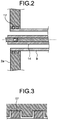
- FIG. 2 is an enlarged view of the movable-side flange of the vacuum circuit breaker according to the first embodiment.
- the movable-side insulating support tube 9 is slidably inserted into the hole of the movable-side flange 2a.
- the movable-side insulating support tube 9 is supported by the movable-side flange 2a via the rubber pieces 17.
- FIG. 3 is an enlarged view of the flexible members disposed on the movable-side flange of the vacuum circuit breaker according to the first embodiment.
- Each of rubber pieces 17 disposed on the inner peripheral surface of the movable-side flange 2a is quadrangular in cross-section. It is to be noted that rubber piece 17 may be of circular or elliptical in cross-section.
- the stationary-side insulating support tube 10 is fixed to the stationary-side flange 2b.
- FIG. 4 is an enlarged view of a juncture of the movable-side frame and the vacuum valve in the vacuum circuit breaker according to the first embodiment.
- the movable-side frame 15 is provided with a slide contact 19.
- the slide contact 19 is in contact with the movable conductor 20.
- the movable-side insulating support tube 9 and the stationary-side insulating support tube 10 may be epoxy cast insulators or fiber-reinforced plastics made of organic or glass fibers impregnated with a resin.
- FIG. 5 illustrates a state the arc-extinguishing chamber is being installed in the grounded tank of the vacuum circuit breaker according to the first embodiment.
- the vacuum circuit breaker 50 according to the first embodiment enables the arc-extinguishing chamber 3 to be assembled outside the grounded tank 1 and then inserted into the grounded tank 1. Therefore, the vacuum circuit breaker 50 according to the first embodiment is easy to manufacture, not requiring work that causes the insulating operation rod 14 to pass through the slide contact 19 inside the grounded tank 1.
- the vacuum circuit breaker 50 has a slide structure for the movable-side insulating support tube 9, which is supported by the inner peripheral surface of the movable-side flange 2a, and has the flexible rubber pieces 17 disposed between the movable-side insulating support tube 9 and the movable-side flange 2a.
- the movable-side insulating support tube 9, which is a part of the arc-extinguishing chamber 3, is supported by the movable-side flange 2a via the rubber pieces 17 to be movable along both in an axial direction and in a radial direction of the arc-extinguishing chamber 3.
- the movable-side insulating support tube 9 it becomes possible to make the movable-side insulating support tube 9 to have a reduced wall thickness and a smaller outside diameter.
- the vacuum circuit breaker 50 Since the movable-side insulating support tube 9, which serves as the part of the arc-extinguishing chamber 3, is axially movable, the vacuum circuit breaker 50 according to the first embodiment is capable of absorbing a difference in length between the grounded tank 1 and the arc-extinguishing chamber 3.
- the vacuum valve 4 is connected at both ends to the movable-side frame 15 and the stationary-side frame 16 with the bolts 25, even when the vacuum circuit breaker 50 according to the first embodiment has vibration during opening and closing operation, a movable side of arc-extinguishing chamber 6 and a stationary side of arc-extinguishing chamber 7 have the same vibration. This suppresses abrasion at the slide contact 19 and temperature rise at a contact part of the slide contact 19.
- FIG. 6 illustrates cross-sectional shapes of flexible member variations disposed on the movable-side flange of the vacuum circuit breaker according to the first embodiment.
- the movable-side insulating support tube 9 of the vacuum circuit breaker 50 is supported by the movable-side flange 2a to be axially movable, even when the movable contact 5a is subject to a continued push in a closed state, no load is applied to a part where the movable-side flange 2a supports the movable-side insulating support tube 9 via the rubber pieces 17.
- the movable-side insulating support tube 9 is therefore not required to have a larger diameter by having an increased wall thickness for the purpose of having mechanical strength to withstand a continued load, and the vacuum circuit breaker 50 is enabled to be smaller in size and lighter in weight.
- the arc-extinguishing chamber 3 is prevented from decreasing in strength due to the bending load that is proportional to mass and vibrational acceleration of the arc-extinguishing chamber 3.
- FIG. 7 is an enlarged view of the movable-side flange of the vacuum circuit breaker according to the second embodiment of the present invention.
- the vacuum circuit breaker 50 according to the second embodiment is such that the movable-side insulating support tube 9 has, at an end opposite from an end connected to the movable-side frame 15, a metal ring 11 fixed to its outer periphery. The metal ring 11 abuts against the inner peripheral surface of the movable-side flange 2a via the rubber pieces 17.
- the movable-side insulating support tube 9 is axially and radially movable and is not easily subject to a tensile load and a bending load.
- deformation of the movable-side insulating support tube 9 can be suppressed and wall thickness of the movable-side insulating support tube 9 can be further reduced.
Landscapes
- Engineering & Computer Science (AREA)
- Power Engineering (AREA)
- Gas-Insulated Switchgears (AREA)
- High-Tension Arc-Extinguishing Switches Without Spraying Means (AREA)
Abstract
Description
- The present invention relates to a vacuum circuit breaker that includes an arc-extinguishing chamber using a vacuum valve.
- As disclosed in Patent Literature 1, a vacuum circuit breaker includes an arc-extinguishing chamber. The arc-extinguishing chamber uses a vacuum valve, performs current interruption, and is housed in a grounded tank. The arc-extinguishing chamber is composed by connecting a plurality of components including: a movable-side insulating support tube; a movable-side frame; the vacuum valve; a stationary-side frame; and a stationary-side insulating support tube. Each end of the grounded tank is sealed with a flange, and the movable-side insulating support tube and the stationary-side insulating support tube are fixed to the flanges, respectively.
- Dimensional variation of the arc-extinguishing chamber, which is an assemblage of the plurality of components, results from errors in manufacturing and assembly of the components. For this reason, a structure that absorbs a difference in length between the grounded tank and the arc-extinguishing chamber is necessary for the arc-extinguishing chamber to be disposed in the grounded tank. Accordingly, a slide contact structure is provided at a movable-side end of the vacuum valve to absorb the difference in length between the grounded tank and the arc-extinguishing chamber while ensuring electrical conductivity.
- Patent Literature 1:
PCT International Publication No. 2012/063501 - Since a clearance for a contact part of a slide contact is extremely narrow, a continued bending load proportional to mass and vibrational acceleration of the arc-extinguishing chamber is applied to the movable-side insulating support tube. The movable-side insulating support tube is fixed at an end to the movable-side flange, which seals the end of the grounded tank, so that the bending load applied to the movable-side insulating support tube causes a load on a juncture of the movable-side insulating support tube and the movable-side flange. The continued load on the juncture of the movable-side insulating support tube and the movable-side flange leads to fatigue at the juncture, thus problematically causing the arc-extinguishing chamber to have a decreased strength.
- The present invention has been made in view of the above, and an object of the present invention is to obtain a vacuum circuit breaker that prevents decrease in strength of an arc-extinguishing chamber, which might be caused by a continued load on a juncture of a movable-side insulating support tube and a movable-side flange.
- In order to solve the above problems and achieve the object, the present invention includes: a tubular grounded tank hermetically containing an insulating gas; a vacuum valve that is insulated and supported inside the grounded tank and includes a movable contact and a stationary contact; a movable conductor electrically connected to the movable contact; a stationary conductor electrically connected to the stationary contact; a movable-side external conductor and a stationary-side external conductor that are disposed respectively in a pair of bushings extending upward from the grounded tank; a movable-side frame electrically connecting a lower end of the movable-side external conductor to the movable conductor; a stationary-side frame electrically connecting a lower end of the stationary-side external conductor to the stationary conductor; and an insulating operation rod connected to an operating device that is disposed outside the grounded tank to operate the movable contact. The present invention also includes: a movable-side insulating support tube that supports the movable-side frame and insulates the movable-side frame from the grounded tank; a stationary-side insulating support tube that supports the stationary-side frame and insulates the stationary-side frame from the grounded tank; a movable-side flange that covers a movable-side end of the grounded tank and includes a hole allowing passage of the movable-side insulating support tube; and a flexible member on an inner peripheral surface of the movable-side flange. An arc-extinguishing chamber is formed by connection of the movable-side insulating support tube, the movable-side frame, the vacuum valve, the stationary-side frame, and the stationary-side insulating support tube, and is housed in the grounded tank. The movable-side insulating support tube is supported, at an end opposite from an end connected to the movable-side frame, by the movable-side flange via the flexible member and is movable along an axial direction and a radial direction of the arc-extinguishing chamber.
- A vacuum circuit breaker according to the present invention prevents decrease in strength of an arc-extinguishing chamber that might be caused by a continued load on a juncture of a movable-side insulating support tube and a movable-side flange.
-
-
FIG. 1 illustrates structure of a vacuum circuit breaker according to a first embodiment of the present invention. -
FIG. 2 is an enlarged view of a movable-side flange of the vacuum circuit breaker according to the first embodiment. -
FIG. 3 is an enlarged view of flexible members disposed on the movable-side flange of the vacuum circuit breaker according to the first embodiment. -
FIG. 4 is an enlarged view of a juncture of a movable-side frame and a vacuum valve in the vacuum circuit breaker according to the first embodiment. -
FIG. 5 illustrates a state an arc-extinguishing chamber is being arranged in a grounded tank of the vacuum circuit breaker according to the first embodiment. -
FIG. 6 illustrates cross-sectional shapes of flexible member variations disposed on the movable-side flange of the vacuum circuit breaker according to the first embodiment. -
FIG. 7 is an enlarged view of a movable-side flange of a vacuum circuit breaker according to a second embodiment of the present invention. - With reference to the drawings, a detailed description is hereinafter provided of vacuum circuit breakers according to embodiments of the present invention. It is to be noted that these embodiments are not restrictive of the present invention.
-
FIG. 1 illustrates structure of a vacuum circuit breaker according to the first embodiment of the present invention. As illustrated inFIG. 1 , thevacuum circuit breaker 50 according to the first embodiment includes: a tubular grounded tank 1 hermetically containing an insulating gas; avacuum valve 4 that is insulated and supported inside the grounded tank 1 and includes amovable contact 5a and astationary contact 5b; amovable conductor 20 electrically connected to themovable contact 5a; astationary conductor 21 electrically connected to thestationary contact 5b; and a movable-sideexternal conductor 23 and a stationary-sideexternal conductor 24 that are disposed in a pair ofbushings 22 extending upward from the grounded tank 1. Thevacuum circuit breaker 50 also includes: a movable-side frame 15 electrically connecting a lower end of the movable-sideexternal conductor 23 to themovable conductor 20; a stationary-side frame 16 electrically connecting a lower end of the stationary-sideexternal conductor 24 to thestationary conductor 21; aninsulating operation rod 14 connected to anoperating device 12 disposed outside the grounded tank 1 to operate themovable contact 5a; a movable-sideinsulating support tube 9 that supports the movable-side frame 15 and insulates the movable-side frame 15 from the grounded tank 1; and a stationary-sideinsulating support tube 10 that supports the stationary-side frame 16 and insulates the stationary-side frame 16 from the grounded tank 1. A movable-side end of the grounded tank 1 is covered by a movable-side flange 2a that includes a hole allowing passage of the movable-sideinsulating support tube 9. A stationary-side end of the grounded tank 1 is covered by a stationary-side flange 2b.Rubber pieces 17 are disposed as flexible members on an inner peripheral surface of the movable-side flange 2a. An arc-extinguishingchamber 3 is formed by connection of: the movable-sideinsulating support tube 9; the movable-side frame 15; thevacuum valve 4; the stationary-side frame 16; and the stationary-sideinsulating support tube 10, and is housed in the grounded tank 1. Thevacuum valve 4 is fixed to the movable-side frame 15 and the stationary-side frame 16 withbolts 25. - The
movable contact 5a is configured to receive driving force from theoperating device 12 via alink mechanism 13, theinsulating operation rod 14, and themovable conductor 20. Themovable contact 5a can take a supply position to touch thestationary contact 5b and an interruption position to separate from thestationary contact 5b. During closing operation, acontact pressure spring 8 applies, to theinsulating operation rod 14, force that pushes themovable contact 5a toward thestationary contact 5b. Therefore, electrical conductivity is ensured in a state themovable contact 5a and thestationary contact 5b are closed. -
FIG. 2 is an enlarged view of the movable-side flange of the vacuum circuit breaker according to the first embodiment. The movable-sideinsulating support tube 9 is slidably inserted into the hole of the movable-side flange 2a. The movable-sideinsulating support tube 9 is supported by the movable-side flange 2a via therubber pieces 17.FIG. 3 is an enlarged view of the flexible members disposed on the movable-side flange of the vacuum circuit breaker according to the first embodiment. Each ofrubber pieces 17 disposed on the inner peripheral surface of the movable-side flange 2a is quadrangular in cross-section. It is to be noted thatrubber piece 17 may be of circular or elliptical in cross-section. - The stationary-side
insulating support tube 10 is fixed to the stationary-side flange 2b. -
FIG. 4 is an enlarged view of a juncture of the movable-side frame and the vacuum valve in the vacuum circuit breaker according to the first embodiment. The movable-side frame 15 is provided with aslide contact 19. Theslide contact 19 is in contact with themovable conductor 20. - The movable-side
insulating support tube 9 and the stationary-side insulatingsupport tube 10 may be epoxy cast insulators or fiber-reinforced plastics made of organic or glass fibers impregnated with a resin. -
FIG. 5 illustrates a state the arc-extinguishing chamber is being installed in the grounded tank of the vacuum circuit breaker according to the first embodiment. Thevacuum circuit breaker 50 according to the first embodiment enables the arc-extinguishingchamber 3 to be assembled outside the grounded tank 1 and then inserted into the grounded tank 1. Therefore, thevacuum circuit breaker 50 according to the first embodiment is easy to manufacture, not requiring work that causes theinsulating operation rod 14 to pass through theslide contact 19 inside the grounded tank 1. - The
vacuum circuit breaker 50 according to the first embodiment has a slide structure for the movable-sideinsulating support tube 9, which is supported by the inner peripheral surface of the movable-side flange 2a, and has theflexible rubber pieces 17 disposed between the movable-sideinsulating support tube 9 and the movable-side flange 2a. The movable-sideinsulating support tube 9, which is a part of the arc-extinguishingchamber 3, is supported by the movable-side flange 2a via therubber pieces 17 to be movable along both in an axial direction and in a radial direction of the arc-extinguishingchamber 3. Therefore, a bending load and a tensile load are less likely to be applied to the movable-sideinsulating support tube 9. Accordingly, it becomes possible to make the movable-side insulatingsupport tube 9 to have a reduced wall thickness and a smaller outside diameter. - Since the movable-side insulating
support tube 9, which serves as the part of the arc-extinguishingchamber 3, is axially movable, thevacuum circuit breaker 50 according to the first embodiment is capable of absorbing a difference in length between the grounded tank 1 and the arc-extinguishingchamber 3. - Since the
vacuum valve 4 is connected at both ends to the movable-side frame 15 and the stationary-side frame 16 with thebolts 25, even when thevacuum circuit breaker 50 according to the first embodiment has vibration during opening and closing operation, a movable side of arc-extinguishingchamber 6 and a stationary side of arc-extinguishingchamber 7 have the same vibration. This suppresses abrasion at theslide contact 19 and temperature rise at a contact part of theslide contact 19. -
FIG. 6 illustrates cross-sectional shapes of flexible member variations disposed on the movable-side flange of the vacuum circuit breaker according to the first embodiment. Disposing the O-rings 18 of circular cross-section on the inner peripheral surface of the movable-side flange 2a, with an outer peripheral surface of the movable-side insulatingsupport tube 9 partly machined, enables a difference to be caused between an internal air pressure of the movable-side frame 15 and the movable-side insulatingsupport tube 9 and an internal air pressure of the grounded tank 1. - Since the movable-side insulating
support tube 9 of thevacuum circuit breaker 50 according to the first embodiment is supported by the movable-side flange 2a to be axially movable, even when themovable contact 5a is subject to a continued push in a closed state, no load is applied to a part where the movable-side flange 2a supports the movable-side insulatingsupport tube 9 via therubber pieces 17. The movable-side insulatingsupport tube 9 is therefore not required to have a larger diameter by having an increased wall thickness for the purpose of having mechanical strength to withstand a continued load, and thevacuum circuit breaker 50 is enabled to be smaller in size and lighter in weight. Since the movable-side insulatingsupport tube 9 supported by the movable-side flange 2a via therubber pieces 17 is also radially movable, the arc-extinguishingchamber 3 is prevented from decreasing in strength due to the bending load that is proportional to mass and vibrational acceleration of the arc-extinguishingchamber 3. -
FIG. 7 is an enlarged view of the movable-side flange of the vacuum circuit breaker according to the second embodiment of the present invention. Thevacuum circuit breaker 50 according to the second embodiment is such that the movable-side insulatingsupport tube 9 has, at an end opposite from an end connected to the movable-side frame 15, ametal ring 11 fixed to its outer periphery. Themetal ring 11 abuts against the inner peripheral surface of the movable-side flange 2a via therubber pieces 17. Thus the movable-side insulatingsupport tube 9 is axially and radially movable and is not easily subject to a tensile load and a bending load. By installing themetal ring 11, deformation of the movable-side insulatingsupport tube 9 can be suppressed and wall thickness of the movable-side insulatingsupport tube 9 can be further reduced. - Disposing the O-
rings 18 on the inner peripheral surface of the movable-side flange 2a as in thevacuum circuit breaker 50 according to the first embodiment, with an outer peripheral surface of themetal ring 11 partly machined, enables a difference to be caused between an internal air pressure of the movable-side frame 15 and the movable-side insulatingsupport tube 9 and an internal air pressure of the grounded tank 1. - The above structures illustrated in the embodiments are illustrative of contents of the present invention, can be combined with other techniques that are publicly known and can be partly omitted or changed without departing from the gist of the present invention.
- 1 grounded tank; 2a movable-side flange; 2b stationary-side flange; 3 arc-extinguishing chamber; 4 vacuum valve; 5a movable contact; 5b stationary contact; 6 movable side of arc-extinguishing chamber; 7 stationary side of arc-extinguishing chamber; 8 contact pressure spring; 9 movable-side insulating support tube; 10 stationary-side insulating support tube; 11 metal ring; 12 operating device; 13 link mechanism; 14 insulating operation rod; 15 movable-side frame; 16 stationary-side frame; 17 rubber piece; 18 O-ring; 19 slide contact; 20 movable conductor; 21 stationary conductor; 22 bushing; 23 movable-side external conductor; 24 stationary-side external conductor; 25 bolt; 50 vacuum circuit breaker.
Claims (4)
- A vacuum circuit breaker comprising:a grounded tank hermetically containing an insulating gas, the grounded tank being tubular;a vacuum valve insulated and supported inside the grounded tank, the vacuum valve including a movable contact and a stationary contact;a movable conductor electrically connected to the movable contact;a stationary conductor electrically connected to the stationary contact;a movable-side external conductor and a stationary-side external conductor disposed in a pair of bushings extending upward from the grounded tank;a movable-side frame electrically connecting a lower end of the movable-side external conductor to the movable conductor;a stationary-side frame electrically connecting a lower end of the stationary-side external conductor to the stationary conductor;an insulating operation rod connected to an operating device disposed outside the grounded tank to operate the movable contact;a movable-side insulating support tube to support the movable-side frame and insulates thereof from the grounded tank;a stationary-side insulating support tube to support the stationary-side frame and insulates thereof frame from the grounded tank;a movable-side flange covering a movable-side end of the grounded tank, the movable-side flange including a hole allowing passage of the movable-side insulating support tube; anda flexible member on an inner peripheral surface of the movable-side flange, whereinan arc-extinguishing chamber is formed by connecting:the movable-side insulating support tube;the movable-side frame;the vacuum valve;the stationary-side frame; andthe stationary-side insulating support tube, and the arc-extinguishing chamber is housed in the grounded tank, andthe movable-side insulating support tube is supported, at an end opposite from an end connected to the movable-side frame, by the movable-side flange via the flexible member and is movable along an axial direction and a radial direction of the arc-extinguishing chamber.
- The vacuum circuit breaker according to claim 1, wherein the movable-side frame, the vacuum valve, and the stationary-side frame are connected by bolts.
- The vacuum circuit breaker according to claim 1, wherein the movable-side insulating support tube has, at the end opposite from the end connected to the movable-side frame, a metal ring fixed to an outer periphery thereof.
- The vacuum circuit breaker according to claim 1, wherein the flexible member is an O-ring.
Applications Claiming Priority (1)
| Application Number | Priority Date | Filing Date | Title |
|---|---|---|---|
| PCT/JP2019/003466 WO2020157933A1 (en) | 2019-01-31 | 2019-01-31 | Vacuum-circuit breaker |
Publications (3)
| Publication Number | Publication Date |
|---|---|
| EP3920203A1 true EP3920203A1 (en) | 2021-12-08 |
| EP3920203A4 EP3920203A4 (en) | 2022-01-26 |
| EP3920203B1 EP3920203B1 (en) | 2023-05-24 |
Family
ID=68613366
Family Applications (1)
| Application Number | Title | Priority Date | Filing Date |
|---|---|---|---|
| EP19912583.2A Active EP3920203B1 (en) | 2019-01-31 | 2019-01-31 | Vacuum-circuit breaker |
Country Status (4)
| Country | Link |
|---|---|
| US (1) | US11462376B2 (en) |
| EP (1) | EP3920203B1 (en) |
| JP (1) | JP6608097B1 (en) |
| WO (1) | WO2020157933A1 (en) |
Families Citing this family (2)
| Publication number | Priority date | Publication date | Assignee | Title |
|---|---|---|---|---|
| US10919014B2 (en) * | 2018-04-09 | 2021-02-16 | Craig Technical Consulting, Inc. | High-load vacuum chamber motion feedthrough systems and methods |
| CN115841928B (en) * | 2022-12-15 | 2023-10-31 | 江苏省埃迪机电设备实业有限公司 | A multi-purpose ultra-high voltage circuit breaker composite bellows assembly |
Family Cites Families (16)
| Publication number | Priority date | Publication date | Assignee | Title |
|---|---|---|---|---|
| JPH0384531U (en) * | 1989-12-20 | 1991-08-27 | ||
| DE19517287A1 (en) * | 1995-05-11 | 1996-11-14 | Abb Patent Gmbh | Electric switching unit for medium and high voltage |
| DE102004029871A1 (en) * | 2004-06-16 | 2006-02-16 | Siemens Ag | Circuit breaker with an interrupter arranged within an encapsulating housing |
| KR101153478B1 (en) * | 2008-04-07 | 2012-06-11 | 미쓰비시덴키 가부시키가이샤 | Vacuum breaker and gas insulated switchgear using the same |
| KR101300900B1 (en) * | 2009-10-29 | 2013-08-27 | 미쓰비시덴키 가부시키가이샤 | Tank-type vacuum interrupter |
| JP5297339B2 (en) * | 2009-10-29 | 2013-09-25 | 三菱電機株式会社 | Tank type vacuum circuit breaker |
| CN102484360B (en) * | 2009-10-29 | 2014-08-27 | 三菱电机株式会社 | Power switching device |
| KR101314471B1 (en) | 2010-02-23 | 2013-10-07 | 미쓰비시덴키 가부시키가이샤 | Power switching device |
| DE112010005871B4 (en) * | 2010-09-13 | 2016-03-17 | Mitsubishi Electric Corporation | Gas-insulated electrical appliance |
| JP5183831B2 (en) * | 2010-11-12 | 2013-04-17 | 三菱電機株式会社 | Gas insulated switchgear |
| DE112011104424B4 (en) * | 2010-12-17 | 2019-03-28 | Mitsubishi Electric Corporation | Gas-insulated switchgear |
| JP5579323B2 (en) * | 2011-07-07 | 2014-08-27 | 三菱電機株式会社 | Electromagnetic operation device |
| JP5796425B2 (en) | 2011-09-07 | 2015-10-21 | 株式会社明電舎 | Tank type vacuum circuit breaker |
| AU2013321871B2 (en) * | 2012-09-26 | 2016-01-07 | Mitsubishi Electric Corporation | Power opening/closing device |
| US20140374383A1 (en) * | 2013-06-25 | 2014-12-25 | Tetsu Shioiri | Tank-type vacuum circuit breaker |
| EP2975710B1 (en) * | 2014-07-18 | 2017-09-06 | General Electric Technology GmbH | Circuit breaker with an insulating hollow tube |
-
2019
- 2019-01-31 JP JP2019529952A patent/JP6608097B1/en active Active
- 2019-01-31 US US17/295,554 patent/US11462376B2/en active Active
- 2019-01-31 EP EP19912583.2A patent/EP3920203B1/en active Active
- 2019-01-31 WO PCT/JP2019/003466 patent/WO2020157933A1/en not_active Ceased
Also Published As
| Publication number | Publication date |
|---|---|
| JPWO2020157933A1 (en) | 2021-02-18 |
| US20220013313A1 (en) | 2022-01-13 |
| WO2020157933A1 (en) | 2020-08-06 |
| EP3920203B1 (en) | 2023-05-24 |
| JP6608097B1 (en) | 2019-11-20 |
| EP3920203A4 (en) | 2022-01-26 |
| US11462376B2 (en) | 2022-10-04 |
Similar Documents
| Publication | Publication Date | Title |
|---|---|---|
| EP3920203B1 (en) | Vacuum-circuit breaker | |
| CN108701564B (en) | Device and method for guiding a switching lever of a high-voltage circuit breaker | |
| JP5183831B2 (en) | Gas insulated switchgear | |
| WO2011052206A1 (en) | Tank-type vacuum interrupter | |
| US20180025870A1 (en) | Tank type vacuum circuit breaker | |
| JP2016081697A (en) | Vacuum circuit breaker | |
| JP2011229195A (en) | Tank-shaped vacuum circuit-breaker | |
| JP2011097686A (en) | Gas-insulated electric apparatus | |
| CN101192481B (en) | Earthing switch | |
| EP3767763B1 (en) | Gas-insulated switching device | |
| WO2017010066A1 (en) | Interrupter for power system | |
| KR102282700B1 (en) | switching device arrangement | |
| US10233969B2 (en) | Heat resistant structure for shaft retainer, and actuator | |
| EP3370243A1 (en) | Vacuum circuit breaker | |
| EP4583138A1 (en) | Vacuum valve and vacuum circuit breaker | |
| JP6130633B2 (en) | Resin mold vacuum valve | |
| EP4412011B1 (en) | Tank type circuit-breaker | |
| JP2018053945A (en) | Vibration prevention device | |
| JP4653558B2 (en) | Vacuum valve | |
| JP2014120250A (en) | Vacuum switch gear | |
| US10056741B2 (en) | Mobile pole and cutting device | |
| US20170133181A1 (en) | Avoiding incorrect orientations of a drive rod of a power switch | |
| CN215616261U (en) | Mounting mechanism for lining in hole | |
| JP2010282837A (en) | Vacuum valve | |
| EP4343806A1 (en) | Operation apparatus |
Legal Events
| Date | Code | Title | Description |
|---|---|---|---|
| STAA | Information on the status of an ep patent application or granted ep patent |
Free format text: STATUS: THE INTERNATIONAL PUBLICATION HAS BEEN MADE |
|
| PUAI | Public reference made under article 153(3) epc to a published international application that has entered the european phase |
Free format text: ORIGINAL CODE: 0009012 |
|
| STAA | Information on the status of an ep patent application or granted ep patent |
Free format text: STATUS: REQUEST FOR EXAMINATION WAS MADE |
|
| 17P | Request for examination filed |
Effective date: 20210503 |
|
| AK | Designated contracting states |
Kind code of ref document: A1 Designated state(s): AL AT BE BG CH CY CZ DE DK EE ES FI FR GB GR HR HU IE IS IT LI LT LU LV MC MK MT NL NO PL PT RO RS SE SI SK SM TR |
|
| A4 | Supplementary search report drawn up and despatched |
Effective date: 20220104 |
|
| RIC1 | Information provided on ipc code assigned before grant |
Ipc: H01H 33/666 20060101ALI20211221BHEP Ipc: H01H 33/56 20060101ALI20211221BHEP Ipc: H01H 33/66 20060101ALI20211221BHEP Ipc: H01H 33/53 20060101AFI20211221BHEP |
|
| DAV | Request for validation of the european patent (deleted) | ||
| DAX | Request for extension of the european patent (deleted) | ||
| GRAP | Despatch of communication of intention to grant a patent |
Free format text: ORIGINAL CODE: EPIDOSNIGR1 |
|
| STAA | Information on the status of an ep patent application or granted ep patent |
Free format text: STATUS: GRANT OF PATENT IS INTENDED |
|
| RIC1 | Information provided on ipc code assigned before grant |
Ipc: H01H 33/666 20060101ALI20220707BHEP Ipc: H01H 33/56 20060101ALI20220707BHEP Ipc: H01H 33/66 20060101ALI20220707BHEP Ipc: H01H 33/53 20060101AFI20220707BHEP |
|
| INTG | Intention to grant announced |
Effective date: 20220727 |
|
| GRAJ | Information related to disapproval of communication of intention to grant by the applicant or resumption of examination proceedings by the epo deleted |
Free format text: ORIGINAL CODE: EPIDOSDIGR1 |
|
| STAA | Information on the status of an ep patent application or granted ep patent |
Free format text: STATUS: REQUEST FOR EXAMINATION WAS MADE |
|
| INTC | Intention to grant announced (deleted) | ||
| GRAP | Despatch of communication of intention to grant a patent |
Free format text: ORIGINAL CODE: EPIDOSNIGR1 |
|
| STAA | Information on the status of an ep patent application or granted ep patent |
Free format text: STATUS: GRANT OF PATENT IS INTENDED |
|
| INTG | Intention to grant announced |
Effective date: 20221206 |
|
| GRAS | Grant fee paid |
Free format text: ORIGINAL CODE: EPIDOSNIGR3 |
|
| GRAA | (expected) grant |
Free format text: ORIGINAL CODE: 0009210 |
|
| STAA | Information on the status of an ep patent application or granted ep patent |
Free format text: STATUS: THE PATENT HAS BEEN GRANTED |
|
| AK | Designated contracting states |
Kind code of ref document: B1 Designated state(s): AL AT BE BG CH CY CZ DE DK EE ES FI FR GB GR HR HU IE IS IT LI LT LU LV MC MK MT NL NO PL PT RO RS SE SI SK SM TR |
|
| REG | Reference to a national code |
Ref country code: GB Ref legal event code: FG4D |
|
| REG | Reference to a national code |
Ref country code: CH Ref legal event code: EP |
|
| REG | Reference to a national code |
Ref country code: DE Ref legal event code: R096 Ref document number: 602019029404 Country of ref document: DE |
|
| REG | Reference to a national code |
Ref country code: AT Ref legal event code: REF Ref document number: 1570071 Country of ref document: AT Kind code of ref document: T Effective date: 20230615 |
|
| P01 | Opt-out of the competence of the unified patent court (upc) registered |
Effective date: 20230517 |
|
| REG | Reference to a national code |
Ref country code: IE Ref legal event code: FG4D |
|
| REG | Reference to a national code |
Ref country code: LT Ref legal event code: MG9D |
|
| REG | Reference to a national code |
Ref country code: NL Ref legal event code: MP Effective date: 20230524 |
|
| REG | Reference to a national code |
Ref country code: AT Ref legal event code: MK05 Ref document number: 1570071 Country of ref document: AT Kind code of ref document: T Effective date: 20230524 |
|
| PG25 | Lapsed in a contracting state [announced via postgrant information from national office to epo] |
Ref country code: SE Free format text: LAPSE BECAUSE OF FAILURE TO SUBMIT A TRANSLATION OF THE DESCRIPTION OR TO PAY THE FEE WITHIN THE PRESCRIBED TIME-LIMIT Effective date: 20230524 Ref country code: PT Free format text: LAPSE BECAUSE OF FAILURE TO SUBMIT A TRANSLATION OF THE DESCRIPTION OR TO PAY THE FEE WITHIN THE PRESCRIBED TIME-LIMIT Effective date: 20230925 Ref country code: NO Free format text: LAPSE BECAUSE OF FAILURE TO SUBMIT A TRANSLATION OF THE DESCRIPTION OR TO PAY THE FEE WITHIN THE PRESCRIBED TIME-LIMIT Effective date: 20230824 Ref country code: NL Free format text: LAPSE BECAUSE OF FAILURE TO SUBMIT A TRANSLATION OF THE DESCRIPTION OR TO PAY THE FEE WITHIN THE PRESCRIBED TIME-LIMIT Effective date: 20230524 Ref country code: ES Free format text: LAPSE BECAUSE OF FAILURE TO SUBMIT A TRANSLATION OF THE DESCRIPTION OR TO PAY THE FEE WITHIN THE PRESCRIBED TIME-LIMIT Effective date: 20230524 Ref country code: AT Free format text: LAPSE BECAUSE OF FAILURE TO SUBMIT A TRANSLATION OF THE DESCRIPTION OR TO PAY THE FEE WITHIN THE PRESCRIBED TIME-LIMIT Effective date: 20230524 |
|
| PG25 | Lapsed in a contracting state [announced via postgrant information from national office to epo] |
Ref country code: RS Free format text: LAPSE BECAUSE OF FAILURE TO SUBMIT A TRANSLATION OF THE DESCRIPTION OR TO PAY THE FEE WITHIN THE PRESCRIBED TIME-LIMIT Effective date: 20230524 Ref country code: PL Free format text: LAPSE BECAUSE OF FAILURE TO SUBMIT A TRANSLATION OF THE DESCRIPTION OR TO PAY THE FEE WITHIN THE PRESCRIBED TIME-LIMIT Effective date: 20230524 Ref country code: LV Free format text: LAPSE BECAUSE OF FAILURE TO SUBMIT A TRANSLATION OF THE DESCRIPTION OR TO PAY THE FEE WITHIN THE PRESCRIBED TIME-LIMIT Effective date: 20230524 Ref country code: LT Free format text: LAPSE BECAUSE OF FAILURE TO SUBMIT A TRANSLATION OF THE DESCRIPTION OR TO PAY THE FEE WITHIN THE PRESCRIBED TIME-LIMIT Effective date: 20230524 Ref country code: IS Free format text: LAPSE BECAUSE OF FAILURE TO SUBMIT A TRANSLATION OF THE DESCRIPTION OR TO PAY THE FEE WITHIN THE PRESCRIBED TIME-LIMIT Effective date: 20230924 Ref country code: HR Free format text: LAPSE BECAUSE OF FAILURE TO SUBMIT A TRANSLATION OF THE DESCRIPTION OR TO PAY THE FEE WITHIN THE PRESCRIBED TIME-LIMIT Effective date: 20230524 Ref country code: GR Free format text: LAPSE BECAUSE OF FAILURE TO SUBMIT A TRANSLATION OF THE DESCRIPTION OR TO PAY THE FEE WITHIN THE PRESCRIBED TIME-LIMIT Effective date: 20230825 |
|
| PG25 | Lapsed in a contracting state [announced via postgrant information from national office to epo] |
Ref country code: FI Free format text: LAPSE BECAUSE OF FAILURE TO SUBMIT A TRANSLATION OF THE DESCRIPTION OR TO PAY THE FEE WITHIN THE PRESCRIBED TIME-LIMIT Effective date: 20230524 |
|
| PG25 | Lapsed in a contracting state [announced via postgrant information from national office to epo] |
Ref country code: SK Free format text: LAPSE BECAUSE OF FAILURE TO SUBMIT A TRANSLATION OF THE DESCRIPTION OR TO PAY THE FEE WITHIN THE PRESCRIBED TIME-LIMIT Effective date: 20230524 |
|
| PG25 | Lapsed in a contracting state [announced via postgrant information from national office to epo] |
Ref country code: SM Free format text: LAPSE BECAUSE OF FAILURE TO SUBMIT A TRANSLATION OF THE DESCRIPTION OR TO PAY THE FEE WITHIN THE PRESCRIBED TIME-LIMIT Effective date: 20230524 Ref country code: SK Free format text: LAPSE BECAUSE OF FAILURE TO SUBMIT A TRANSLATION OF THE DESCRIPTION OR TO PAY THE FEE WITHIN THE PRESCRIBED TIME-LIMIT Effective date: 20230524 Ref country code: RO Free format text: LAPSE BECAUSE OF FAILURE TO SUBMIT A TRANSLATION OF THE DESCRIPTION OR TO PAY THE FEE WITHIN THE PRESCRIBED TIME-LIMIT Effective date: 20230524 Ref country code: EE Free format text: LAPSE BECAUSE OF FAILURE TO SUBMIT A TRANSLATION OF THE DESCRIPTION OR TO PAY THE FEE WITHIN THE PRESCRIBED TIME-LIMIT Effective date: 20230524 Ref country code: DK Free format text: LAPSE BECAUSE OF FAILURE TO SUBMIT A TRANSLATION OF THE DESCRIPTION OR TO PAY THE FEE WITHIN THE PRESCRIBED TIME-LIMIT Effective date: 20230524 Ref country code: CZ Free format text: LAPSE BECAUSE OF FAILURE TO SUBMIT A TRANSLATION OF THE DESCRIPTION OR TO PAY THE FEE WITHIN THE PRESCRIBED TIME-LIMIT Effective date: 20230524 |
|
| REG | Reference to a national code |
Ref country code: DE Ref legal event code: R097 Ref document number: 602019029404 Country of ref document: DE |
|
| PLBE | No opposition filed within time limit |
Free format text: ORIGINAL CODE: 0009261 |
|
| STAA | Information on the status of an ep patent application or granted ep patent |
Free format text: STATUS: NO OPPOSITION FILED WITHIN TIME LIMIT |
|
| 26N | No opposition filed |
Effective date: 20240227 |
|
| PG25 | Lapsed in a contracting state [announced via postgrant information from national office to epo] |
Ref country code: SI Free format text: LAPSE BECAUSE OF FAILURE TO SUBMIT A TRANSLATION OF THE DESCRIPTION OR TO PAY THE FEE WITHIN THE PRESCRIBED TIME-LIMIT Effective date: 20230524 |
|
| PG25 | Lapsed in a contracting state [announced via postgrant information from national office to epo] |
Ref country code: SI Free format text: LAPSE BECAUSE OF FAILURE TO SUBMIT A TRANSLATION OF THE DESCRIPTION OR TO PAY THE FEE WITHIN THE PRESCRIBED TIME-LIMIT Effective date: 20230524 Ref country code: IT Free format text: LAPSE BECAUSE OF FAILURE TO SUBMIT A TRANSLATION OF THE DESCRIPTION OR TO PAY THE FEE WITHIN THE PRESCRIBED TIME-LIMIT Effective date: 20230524 |
|
| PG25 | Lapsed in a contracting state [announced via postgrant information from national office to epo] |
Ref country code: MC Free format text: LAPSE BECAUSE OF FAILURE TO SUBMIT A TRANSLATION OF THE DESCRIPTION OR TO PAY THE FEE WITHIN THE PRESCRIBED TIME-LIMIT Effective date: 20230524 |
|
| PG25 | Lapsed in a contracting state [announced via postgrant information from national office to epo] |
Ref country code: MC Free format text: LAPSE BECAUSE OF FAILURE TO SUBMIT A TRANSLATION OF THE DESCRIPTION OR TO PAY THE FEE WITHIN THE PRESCRIBED TIME-LIMIT Effective date: 20230524 |
|
| PG25 | Lapsed in a contracting state [announced via postgrant information from national office to epo] |
Ref country code: LU Free format text: LAPSE BECAUSE OF NON-PAYMENT OF DUE FEES Effective date: 20240131 |
|
| GBPC | Gb: european patent ceased through non-payment of renewal fee |
Effective date: 20240131 |
|
| PG25 | Lapsed in a contracting state [announced via postgrant information from national office to epo] |
Ref country code: LU Free format text: LAPSE BECAUSE OF NON-PAYMENT OF DUE FEES Effective date: 20240131 |
|
| PG25 | Lapsed in a contracting state [announced via postgrant information from national office to epo] |
Ref country code: GB Free format text: LAPSE BECAUSE OF NON-PAYMENT OF DUE FEES Effective date: 20240131 |
|
| PG25 | Lapsed in a contracting state [announced via postgrant information from national office to epo] |
Ref country code: BE Free format text: LAPSE BECAUSE OF NON-PAYMENT OF DUE FEES Effective date: 20240131 |
|
| PG25 | Lapsed in a contracting state [announced via postgrant information from national office to epo] |
Ref country code: GB Free format text: LAPSE BECAUSE OF NON-PAYMENT OF DUE FEES Effective date: 20240131 Ref country code: BE Free format text: LAPSE BECAUSE OF NON-PAYMENT OF DUE FEES Effective date: 20240131 |
|
| REG | Reference to a national code |
Ref country code: BE Ref legal event code: MM Effective date: 20240131 |
|
| PG25 | Lapsed in a contracting state [announced via postgrant information from national office to epo] |
Ref country code: BG Free format text: LAPSE BECAUSE OF FAILURE TO SUBMIT A TRANSLATION OF THE DESCRIPTION OR TO PAY THE FEE WITHIN THE PRESCRIBED TIME-LIMIT Effective date: 20230524 |
|
| PG25 | Lapsed in a contracting state [announced via postgrant information from national office to epo] |
Ref country code: BG Free format text: LAPSE BECAUSE OF FAILURE TO SUBMIT A TRANSLATION OF THE DESCRIPTION OR TO PAY THE FEE WITHIN THE PRESCRIBED TIME-LIMIT Effective date: 20230524 |
|
| PG25 | Lapsed in a contracting state [announced via postgrant information from national office to epo] |
Ref country code: IE Free format text: LAPSE BECAUSE OF NON-PAYMENT OF DUE FEES Effective date: 20240131 |
|
| PG25 | Lapsed in a contracting state [announced via postgrant information from national office to epo] |
Ref country code: IE Free format text: LAPSE BECAUSE OF NON-PAYMENT OF DUE FEES Effective date: 20240131 |
|
| REG | Reference to a national code |
Ref country code: DE Ref legal event code: R084 Ref document number: 602019029404 Country of ref document: DE |
|
| PG25 | Lapsed in a contracting state [announced via postgrant information from national office to epo] |
Ref country code: CY Free format text: LAPSE BECAUSE OF FAILURE TO SUBMIT A TRANSLATION OF THE DESCRIPTION OR TO PAY THE FEE WITHIN THE PRESCRIBED TIME-LIMIT; INVALID AB INITIO Effective date: 20190131 |
|
| PG25 | Lapsed in a contracting state [announced via postgrant information from national office to epo] |
Ref country code: HU Free format text: LAPSE BECAUSE OF FAILURE TO SUBMIT A TRANSLATION OF THE DESCRIPTION OR TO PAY THE FEE WITHIN THE PRESCRIBED TIME-LIMIT; INVALID AB INITIO Effective date: 20190131 |
|
| PG25 | Lapsed in a contracting state [announced via postgrant information from national office to epo] |
Ref country code: TR Free format text: LAPSE BECAUSE OF FAILURE TO SUBMIT A TRANSLATION OF THE DESCRIPTION OR TO PAY THE FEE WITHIN THE PRESCRIBED TIME-LIMIT Effective date: 20230524 |
|
| PGFP | Annual fee paid to national office [announced via postgrant information from national office to epo] |
Ref country code: FR Payment date: 20251128 Year of fee payment: 8 |
|
| REG | Reference to a national code |
Ref country code: CH Ref legal event code: U11 Free format text: ST27 STATUS EVENT CODE: U-0-0-U10-U11 (AS PROVIDED BY THE NATIONAL OFFICE) Effective date: 20260201 |
|
| PGFP | Annual fee paid to national office [announced via postgrant information from national office to epo] |
Ref country code: DE Payment date: 20251210 Year of fee payment: 8 |
|
| PGFP | Annual fee paid to national office [announced via postgrant information from national office to epo] |
Ref country code: CH Payment date: 20260201 Year of fee payment: 8 |