EP3919873A1 - Sensor unit and function activation method - Google Patents
Sensor unit and function activation method Download PDFInfo
- Publication number
- EP3919873A1 EP3919873A1 EP19912481.9A EP19912481A EP3919873A1 EP 3919873 A1 EP3919873 A1 EP 3919873A1 EP 19912481 A EP19912481 A EP 19912481A EP 3919873 A1 EP3919873 A1 EP 3919873A1
- Authority
- EP
- European Patent Office
- Prior art keywords
- unit
- signal
- light
- sensor
- pulse wave
- Prior art date
- Legal status (The legal status is an assumption and is not a legal conclusion. Google has not performed a legal analysis and makes no representation as to the accuracy of the status listed.)
- Withdrawn
Links
Images



Classifications
-
- H—ELECTRICITY
- H04—ELECTRIC COMMUNICATION TECHNIQUE
- H04Q—SELECTING
- H04Q9/00—Arrangements in telecontrol or telemetry systems for selectively calling a substation from a main station, in which substation desired apparatus is selected for applying a control signal thereto or for obtaining measured values therefrom
-
- G—PHYSICS
- G01—MEASURING; TESTING
- G01S—RADIO DIRECTION-FINDING; RADIO NAVIGATION; DETERMINING DISTANCE OR VELOCITY BY USE OF RADIO WAVES; LOCATING OR PRESENCE-DETECTING BY USE OF THE REFLECTION OR RERADIATION OF RADIO WAVES; ANALOGOUS ARRANGEMENTS USING OTHER WAVES
- G01S17/00—Systems using the reflection or reradiation of electromagnetic waves other than radio waves, e.g. lidar systems
- G01S17/02—Systems using the reflection of electromagnetic waves other than radio waves
- G01S17/04—Systems determining the presence of a target
-
- G—PHYSICS
- G01—MEASURING; TESTING
- G01D—MEASURING NOT SPECIALLY ADAPTED FOR A SPECIFIC VARIABLE; ARRANGEMENTS FOR MEASURING TWO OR MORE VARIABLES NOT COVERED IN A SINGLE OTHER SUBCLASS; TARIFF METERING APPARATUS; MEASURING OR TESTING NOT OTHERWISE PROVIDED FOR
- G01D21/00—Measuring or testing not otherwise provided for
- G01D21/02—Measuring two or more variables by means not covered by a single other subclass
-
- G—PHYSICS
- G08—SIGNALLING
- G08C—TRANSMISSION SYSTEMS FOR MEASURED VALUES, CONTROL OR SIMILAR SIGNALS
- G08C19/00—Electric signal transmission systems
- G08C19/16—Electric signal transmission systems in which transmission is by pulses
-
- G—PHYSICS
- G08—SIGNALLING
- G08C—TRANSMISSION SYSTEMS FOR MEASURED VALUES, CONTROL OR SIMILAR SIGNALS
- G08C23/00—Non-electrical signal transmission systems, e.g. optical systems
- G08C23/04—Non-electrical signal transmission systems, e.g. optical systems using light waves, e.g. infrared
-
- H—ELECTRICITY
- H04—ELECTRIC COMMUNICATION TECHNIQUE
- H04B—TRANSMISSION
- H04B10/00—Transmission systems employing electromagnetic waves other than radio-waves, e.g. infrared, visible or ultraviolet light, or employing corpuscular radiation, e.g. quantum communication
- H04B10/40—Transceivers
Definitions
- the invention relates to a sensor unit and a function activation method.
- a sensor system having multiple sensor units combined to be able to transmit signals via a connector means is known.
- the sensor units respectively hold identification information, and set respective inherent identification numbers through signal transmission with one another.
- the respective sensor units operate after a delay time determined in correspondence with the respective identification numbers by using a synchronization signal transmitted at a prescribed period from a sensor unit having a specific type number among the sensor units as a start point.
- the delay time of each of the sensor units is determined so that an operation period is consistent with a prescribed period determined for each type information and different from the delay times of other sensor units having the same type information (see Patent Document 1).
- the operation period arbitrarily determined for each type is realized, and interference among those of the same type is avoided.
- Patent Document 1 Japanese Laid-open No. 2014-96697
- the conventional sensor system adopts a configuration in which each sensor unit has a communication function, and the sensor system is provided with a communication unit capable of transmitting a command of sensitivity adjustment or threshold setting with respect to the respective sensor units.
- an objective of the invention is to provide a sensor unit and a function activation method capable of collectively activating a function with respect to multiple sensor units.
- a sensor unit is capable of forming a unit series by connecting multiple sensor units and includes: an activation unit, activating a prescribed function based on a signal from outside; and a signal output unit, outputting a trigger signal for activating the prescribed function to the outside based on the signal from the outside.
- the prescribed function such as the sensitivity adjustment function
- the trigger signal for activating the prescribed function is output to the outside based on the signal from the outside.
- the trigger signal can be transmitted to the adjacent sensor unit in the unit series, such as the sensor unit adjacent on the right.
- the prescribed function such as the sensitivity adjustment function
- the prescribed function with respect to the sensor units can be collectively activated, and the work load for activating the prescribed function, such as the sensitivity adjustment function, in each sensor unit can be reduced.
- the sensor unit may further include a light communication unit capable of light signal transmission and reception.
- the signal output unit may transmit a light signal including the trigger signal to one of the sensor units in the unit series by using the light communication unit
- the light signal including the trigger signal is transmitted to one of the sensor units in the unit series, such as the sensor unit adjacent on the right. Accordingly, a light signal used for another purpose, such as a synchronization signal, can be used to transmit the trigger signal.
- the activation unit may activate the prescribed function based on the trigger signal included in the light signal received from another sensor unit in the unit series by using the light communication unit.
- a light signal is received from the other side in the unit series, such as from the sensor unit adjacent on the left, and the prescribed function is activated based on the trigger signal included in the received light signal. Accordingly, the light signal used for another purpose, such as a synchronization signal, can be used, and, in the case of the slave unit in the unit series, the prescribed function can be easily activated.
- the trigger signal may be represented as a pulse wave.
- the activation unit may activate the prescribed function based on the width of the pulse wave included in the light signal received from another sensor unit in the unit series by using the light communication unit.
- the prescribed function is activated based on the pulse width of the pulse wave included in the light signal. Accordingly, the trigger signal and signals other than the trigger signal in the light signal can be identified, and, in the light signal, the trigger signal and other signals, such as the synchronization signal can be easily used together.
- the trigger signal may be represented as a pulse wave.
- the activation unit may activate the prescribed function based on the width of the pulse wave included in the light signal received from another sensor unit in the unit series by using the light communication unit and the number of the pulse wave included in the light signal during a prescribed period.
- the prescribed function is activated based on the pulse width of the pulse wave included in the light signal and the number of the pulse wave included in the light signal during the prescribed period. Accordingly, the trigger signal and signals other than the trigger signal in the light signal can be easily identified, and, in the light signal, the trigger signal and other signals, such as the synchronization signal can be even more easily used together.
- the trigger signal may be represented as a pulse wave, and the prescribed function may include multiple functions.
- the activation unit may activate one of the functions based on a width of the pulse wave included in the light signal received from another sensor unit in the unit series by using the light communication unit.
- the prescribed function includes multiple functions, and one of the functions is activated based on the pulse width of the pulse wave included in the light signal. Accordingly, the functions included in the prescribed function can be easily chosen and activated.
- the sensor unit may further include an outside input unit receiving an outside input signal.
- the activation unit activates the prescribed function based on the outside input signal.
- the prescribed function is activated based on the outside input signal. Accordingly, by using the outside input signal, which is different from the case of the slave unit, the prescribed function can be easily activated in the case of the master unit in the unit series.
- the sensor unit may further include a light projection unit, emitting light toward a target object; and a light receiving unit, configured to receive light to be able to detect a light receiving amount.
- the sensor unit further includes a light projection unit, emitting light toward a target object; and a light receiving unit, configured to receive light to be able to detect a light receiving amount. Accordingly, a photoelectric sensor unit with which a prescribed function is collectively activated with respect to multiple photoelectric sensor units can be easily realized.
- a sensor system includes multiple sensor units.
- multiple sensor units are included. Accordingly, the respective sensor units can collectively activate the prescribed function, and the work load for activating the prescribed function in each sensor unit can be reduced.
- a function activation method is capable of forming a unit series by connecting multiple sensor units.
- the function activation method includes: an activation step of activating a prescribed function based on a signal from outside; and a signal output step of outputting a trigger signal for activating the prescribed function to the outside based on the signal from the outside.
- the prescribed function such as the sensitivity adjustment function
- the trigger signal for activating the prescribed function is output to the outside based on the signal from the outside.
- the trigger signal can be transmitted to the adjacent sensor unit in the unit series, such as the sensor unit adjacent on the right.
- the prescribed function such as the sensitivity adjustment function
- the prescribed function with respect to the sensor units can be collectively activated, and the work load for activating the prescribed function, such as the sensitivity adjustment function, in each sensor unit can be reduced.
- the signal output step may include transmitting a light signal including the trigger signal to one of the sensor units in the unit series.
- the light signal including the trigger signal is transmitted to one of the sensor units in the unit series, such as the sensor unit adjacent on the right. Accordingly, a light signal used for another purpose, such as a synchronization signal, can be used to transmit the trigger signal.
- the activation step may include: at a time of a slave unit in the unit series, activating the prescribed function based on the trigger signal included in the light signal received from another sensor unit in the unit series.
- a light signal is received from the other side in the unit series, such as from the sensor unit adjacent on the left, and the prescribed function is activated based on the trigger signal included in the received light signal. Accordingly, the light signal used for another purpose, such as a synchronization signal, can be used, and, in the case of the slave unit in the unit series, the prescribed function can be easily activated.
- the trigger signal may be represented as a pulse wave.
- the activation step may include: at a time of a slave unit in the unit series, activating the prescribed function based on a width of the pulse wave included in the light signal received from another sensor unit in the unit series
- the prescribed function is activated based on the pulse width of the pulse wave included in the light signal. Accordingly, the trigger signal and signals other than the trigger signal in the light signal can be identified, and, in the light signal, the trigger signal and other signals, such as the synchronization signal can be easily used together.
- the trigger signal may be represented as a pulse wave.
- the activation step may include: at a time of a slave unit in the unit series, activating the prescribed function based on a width of the pulse wave included in the light signal received from another sensor unit in the unit series and a number of the pulse wave included in the light signal during a prescribed period.
- the prescribed function is activated based on the pulse width of the pulse wave included in the light signal and the number of the pulse wave included in the light signal during the prescribed period. Accordingly, the trigger signal and signals other than the trigger signal in the light signal can be easily identified, and, in the light signal, the trigger signal and other signals, such as the synchronization signal can be even more easily used together.
- the trigger signal may be represented as a pulse wave
- the prescribed function may include multiple functions.
- the activation step may include: at a time of a slave unit in the unit series, activating one of the functions based on a width of the pulse wave included in the light signal received from another sensor unit in the unit series.
- the prescribed function includes multiple functions, and one of the functions is activated based on the pulse width of the pulse wave included in the light signal. Accordingly, the functions included in the prescribed function can be easily chosen and activated.
- the activation step may include: at a time of a master unit in the unit series, activating the prescribed function based on an outside input signal.
- the prescribed function is activated based on the outside input signal. Accordingly, by using the outside input signal, which is different from the case of the slave unit, the prescribed function can be easily activated in the case of the master unit in the unit series.
- the functions of multiple sensor units can be activated collectively.
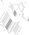
- FIG. 1 is a diagram illustrating a schematic configuration of a sensor system 100 according to an embodiment of the invention.
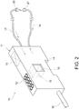
- FIG. 2 is a perspective view exemplifying the appearance of a sensor unit 10 shown in FIG. 1 .
- the sensor system 100 includes multiple sensor units 10. Each of the sensor units 10 is installed to a DIN rail 99, and the sensor units 10 are arranged to be adjacent to one another or provided with a fine gap therebetween. Therefore, the sensor units 10 form a sensor row UL configured by n (n being 2 or more) sensor units SU1 to SUn.
- the sensor unit 10 is, for example, an optical fiber type photoelectric sensor unit. As shown in FIG. 2 , the sensor unit 10 includes a housing 11 in a substantially rectangular parallelepiped shape. On the upper surface of the housing 11, a display unit 12 and an operation unit 13 are provided. The display unit 12 is configured as including a display with seven segments, for example. The operation unit 13 is configured as having multiple buttons, switches, etc., for example. On the lower surface of the housing 11, a groove 14 for attachment to the DIN rail 99 is formed.
- An electric cord 15 is pulled out of the rear surface of the housing 11.
- the electric cord 15 is, for example, connected with a control machine such as a programmable logic controller (PLC), etc.
- PLC programmable logic controller
- an outbound optical fiber cable 16 and an inbound optical fiber cable 17 are pulled out from the front surface of the housing 11.
- the tip of the outbound optical fiber 16 is connected with a sensor head 21, and the tip of the inbound optical fiber 17 is connected with the sensor head 22.
- a light communication window 18 is formed, and on the right side surface of the housing, which is a surface on the positive side of the X-axis in FIG. 2 , a light communication window 19 is formed.
- the light communication windows 18 and 19 are shown as respectively having openings. However, the light communication windows 18 and 19 are actually covered by a filter member.
- the filter member is, for example, a filter that allows infrared light to pass through while cuts off visible light.
- the light communication window 19 of the sensor unit SU1 and the light communication window 18 of the sensor unit SU2 are opposite to each other. Accordingly, as will be described in the following, it is possible to communicate (occasionally referred to as light communication in the following) via light signals in two directions between the adjacent sensor units 10.
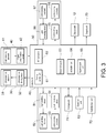
- FIG. 3 is a block diagram exemplifying a schematic internal configuration of the sensor unit 10 shown in FIG. 2 .
- a light projection unit 30, a light receiving unit 40, a light communication unit 50, a control unit 60, a storage unit 71, the operation unit 13, an outside input unit 72, the display unit 12, and an output unit 73 are provided.
- the light projection unit 30 emits light toward a target object (not shown).
- the light projection unit 30, for example, includes a light projection element 31 and a light projection driving circuit 32.
- the light projection element 31 is a light emitting diode, for example.
- the light projection element 31 may also be a light emitting element such as a light emitting diode, a laser diode.
- the light projection driving circuit 32 drives the light projection element 31. Specifically, the light projection driving circuit 32 outputs a driving signal to the light projection element 31 based on a control signal input from the control unit 60.
- the light projection element 31 is driven by the driving signal to emit light.
- the light receiving unit 40 is one in which multiple pixels respectively receive light to obtain light receiving distribution signals to be described afterwards.
- the light receiving unit 40 for example, includes a light receiving element 41 and a signal amplification circuit 42.
- the light receiving element 41 is a photodiode, for example.
- the light receiving element 41 may also be an image capturing element, such as a complementary MOSFET (CMOS) image sensor, a charge coupled device (CMD) image sensor, etc.
- CMOS complementary MOSFET
- CMD charge coupled device
- the light communication unit 50 is configured between the adjacent sensor units 10 to enable light communication in two directions.
- the light communication unit 50 includes a light emitting circuit 51, a light emitting element 52, a light receiving element 53, and a light receiving circuit 54 for performing light communication with the sensor unit 10 adjacent on the left when viewed from itself and a light emitting circuit 55, a light emitting element 56, a light receiving element 57, and a light receiving circuit 58 for performing light communication with the sensor unit adjacent on the right when viewed from itself.
- the light emitting element 52 and the light receiving element 53 are disposed inside the housing 11 so as to be opposite to the light communication window 18 shown in FIG. 2 .
- the light emitting element 52 is, for example, a light emitting diode that emits infrared light, for example, and the light receiving element 53 is, for example, a photodiode.
- the control signal from the control unit 60 is input to the light receiving circuit 51.
- the light emitting circuit 51 makes the light emitting element 52 emit infrared light based on the control signal.
- the light receiving element 53 receives infrared light from the sensor unit 10 arranged to be adjacent on the left in FIG. 1 , for example.
- An electrical signal (referred to as "light receiving signal”) indicating a light receiving amount thereof is output to the control unit 60 via the light receiving circuit 54.
- the light emitting element 56 and the light receiving element 57 are disposed inside the housing 11 so as to be opposite to the light communication window 19 shown in FIG. 2 .
- the light emitting element 56 is, for example, a light emitting diode that emits infrared light, for example, and the light receiving element 57 is, for example, a photodiode.
- the control signal from the control unit 60 is input to the light receiving circuit 55.
- the light emitting circuit 55 makes the light emitting element 56 emit infrared light based on the control signal.
- the light receiving element 57 receives the infrared light from the sensor unit 10 arranged to be adjacent on the right in FIG. 1 , for example.
- the light receiving signal indicating the light receiving amount thereof is output to the control unit 60 via the light receiving circuit 58.
- the control unit 60 is configured to control the operations of the respective units of the sensor unit 10. In addition, the control unit 60 is configured to realize the respective functions to be described afterwards by executing a program stored in the storage unit 71, etc.
- the control unit 60 is configured as including a microprocessor, such as a central processing unit (CPU).
- the control unit 60 includes a timing control unit 61 and an analog-to-digital (A/D) converter 62.
- the timing control unit 61 is configured so as to control the timing of the light emitted from the light projection unit 30 based on a synchronization signal included in the light receiving signal. Specifically, the timing control unit 61 outputs the control signal to the light projection driving circuit 32 at a prescribed timing by using the synchronization signal as a start point.
- the A/D converter 62 samples, quantizes, and encodes the electrical signal input from the signal amplification circuit 42 of the light receiving unit 40 to convert the electrical signal into a digital signal.
- the control unit 60 is configured so as to determine whether there is a target object by comparing the digital signal with a prescribed threshold.
- control unit 60 is configured so as to generate a binary signal, in which "1" stands for the case where there is a corresponding object and "0" stands for the case where there is no target object, according to the determination result, and output the binary signal to the outside via the output unit 73.
- control unit 60 as a functional configuration thereof, includes a determining unit 63, and activation unit 64, and a signal output unit 65, for example.
- the determining unit 63 is configured so as to determine whether the sensor unit 10 of its own is a master unit (referred to as "master”) or a slave unit (referred to as “slave") in the unit series UL.
- the determining unit 63 determines whether the sensor unit 10 is a master unit or a slave unit by recognizing the channel number by using the light communication unit 50, for example.
- the activation unit 64 is configured so as to activate a prescribed function based on a signal from the outside.
- the signal from the outside is, for example, a light signal received by using the light communication unit 50, an outside input signal received by using an outside input unit 72 to be described afterwards, etc.
- the prescribed function is, for example, a sensitivity adjustment function for adjusting the sensitivity of the light receiving signal of the light receiving unit 40 for detecting the target object, a setting function for setting a setting value of various settings of the sensor unit 10.
- the prescribed function is not limited to one, but may also be multiple. In the case where there are multiple prescribed functions, a signal from the outside for activating one of the functions may be different from a signal from the outside for activating another function.
- the activation unit 64 may also generate and output a control signal, for example, to activate the prescribed function.
- the signal output unit 65 is configured so as to output a trigger signal for activating the prescribed function to the outside based on the signal from the outside.
- the trigger signal is, for example, represented by a pulse wave having a prescribed amplitude (referred to as "pulse width" in the following).
- the type of the pulse wave is not particularly limited, and the pulse wave may be, for example, a sine wave, a square wave, a triangular wave, a sawtooth wave, etc.
- the pulse wave may be transmitted at a prescribed period.
- the signal output unit 65 is configured so as to transmit a light signal including the trigger signal to one of the sensor units 10 in the unit series UL, such as the sensor unit 10 adjacent on the right, by using the light communication unit 50. Accordingly, a light signal used for another purpose, such as a synchronization signal, can be used to transmit the trigger signal.
- the activation unit 64 is configured to be different in the case of the master unit and the case of the slave unit in the unit series UL. Specifically, at the time of the slave unit in the unit series UL, the activation unit 64 receives a light signal from the other side in the unit series UL, such as from the sensor unit 10 adjacent on the left, by using the light communication unit 50, and activates the prescribed function based on the trigger signal included in the received light signal. Accordingly, a light signal used for another purpose, such as a synchronization signal, can be used, and, in the case of the slave unit in the unit series UL, the prescribed function can be easily activated.
- the activation unit 64 activates the prescribed function based on the outside input signal received by the outside input unit 72 to be described in the following. Accordingly, by using the outside input signal, which is different from the case of the slave unit, the prescribed function can be easily activated in the case of the master unit in the unit series UL.
- the storage unit 71 is configured to store a program, data, etc. Specifically, the storage unit 71 stores a program executed by the control unit 60 and data such as a set value, etc.
- the storage unit 71 is configured to include a memory such as a read only memory (ROM), a random access memory (RAM), a buffer memory etc.
- the external input unit 72 is configured so as to receive the outside input signal from the outside of the sensor unit 110.
- the outside input signal is an electrical signal, for example.
- the type of the outside input signal which the outside input unit 72 is able to receive is not limited to one type, but may include multiple types.
- the outside input unit 72 outputs the received outside input signal to the control unit 60.
- the output unit 73 is a unit for outputting a signal to the outside of the sensor unit 10.
- the signal output by the output unit 73 is, for example, an electrical signal.
- the type of the signal output by the output unit 73 is not limited to one, but may include multiple types.
- the output unit 73 outputs a signal based on the control signal input from the control unit 60.
- the operation unit 13 is a unit for inputting information to the sensor unit 10. For example, when a user operates a button, a switch, etc., of the operation unit 13, the control unit 60 generates data in correspondence with the operation. Accordingly, information is input to the sensor unit 10.
- the display unit 12 is a unit for outputting information of the sensor unit 10.
- the display unit 12 for example, displays the determination result on whether there is a target object by using a numeral, text, a symbol, etc.
- the display unit 12 displays contents set/to be set in the sensor unit 10, such as a value, an ON/OFF state, an item name, etc., by using a numeral, text, a symbol, etc. Accordingly, the information of the sensor unit 10 is input.
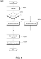
- FIG. 4 is a flowchart exemplifying a schematic operation in which the sensor unit 10 recognizes the channel number.
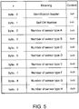
- FIG. 5 is a diagram exemplifying binary data which the sensor unit 10 as a master unit transmits.
- FIG. 6 is a diagram exemplifying binary data which the sensor unit 10 as a slave unit transmits.
- control unit 60 sets both the input port and the output port of the light communication unit 50 to a general input/output allocation, and then sets the output as ON during a prescribed period to output light (S201). Accordingly, infrared light from the light emitting element 56 is emitted in the prescribed period, for example.
- the determining unit 63 determines whether infrared light is received by using the light receiving element 53, for example, after the prescribed period from light starting being output (S202).
- Step 202 In the case where the determination result of Step 202 is that no infrared light is received, it is considered that a sensor unit 10 is not present on the upstream side, such as the adjacent left side, in the unit series UL. Accordingly, the determining unit 63 recognizes itself as in a master unit in the unit series UL (S203). That is, the determining unit 63 recognizes the channel number as "1".
- Step 202 In the case where the determination result of Step 202 is that infrared light is received, it is considered that a sensor unit 10 is present on the upstream side, such as the adjacent left side, in the unit series UL. Accordingly, the determining unit 63 recognizes itself as in a slave unit in the unit series UL (S204). That is, the determining unit 63 recognizes the channel number as a number other than "1".
- the control unit 60 switches the input port and the output port of the light communication unit 50 to a universal asynchronous receiver transmitter (UART) allocation, and then, in the case of the master unit, transmits binary data exemplified in FIG. 5 to the adjacent sensor unit 10, such as the sensor unit 10 adjacent on the right (S205).
- the control unit 60 does not perform Step S205.
- the binary data takes into consideration a difference in the timing at which power is turned on, and is output repeatedly for a predetermined number of times or more.
- the number of each type of the sensor unit 10 also expresses an order m (m being a positive integer) of each type of the sensor unit 10. By inputting data "0x01" as “number of sensor type A”, it is expressed that the order m in a group of the sensor units 10 of the type A is “1 ".
- the control unit 60 transmits the binary data exemplified in FIG. 6 to the adjacent sensor unit 10, such as the sensor unit 10 adjacent on the right, by using the light communication unit 50 (S206).
- the control unit 60 does not perform Step S206.
- the control unit 60 of the sensor unit 10 receiving the binary data recognizes the channel number of itself as "2". That is, the channel number of itself is recognized as a number greater by 1 than the channel number expressed by the "self CH number” of the received binary data.
- the channel number is incremented by 1 to express the channel number as "2”
- data "0x02" is input as the "self CH number”. Accordingly, in the case where data "0x05” has been input to the "self CH number” of the received binary data, data "0x06" is input to the "self CH number” in the binary data to be transmitted.
- Step S206 the control unit 60 ends a channel number recognition process S200.
- each sensor unit 10 recognizes a number greater by 1 than the channel number expressed by the "self CH number" of the received binary data as the channel number.
- FIG. 7 is a waveform diagram exemplifying a light signal OS which the light communication unit 50 shown in FIG. 3 transmits and receives.
- FIG. 8 is a table exemplifying a relationship between a pulse wave included in the light signal OS of the light communication unit 50 shown in FIG. 3 and a use thereof.
- the light signal OS includes three types of pulse waves, i.e., a first pulse wave PW1, a second pulse wave PW2, and a third pulse wave PW3.
- the first pulse wave PW1 has a pulse width Wd1 and is a wave with a period Pe1.
- the second pulse wave PW2 has a pulse width Wd2 greater than the pulse width Wd1 of the first pulse wave PW1 (pulse width Wd1 ⁇ pulse width Wd2), and is a wave with a period Pe2 longer than the period Pe1 of the first pulse wave PW1 (period Pe1 ⁇ period Pe2).
- the third pulse wave PW3 has a pulse width Wd3 greater than the pulse width Wd2 of the second pulse wave PW2 (pulse width Wd2 ⁇ pulse width Wd3), and is a wave with a period Pe3 longer than the period Pe2 of the second pulse wave PW2 (period Pe2 ⁇ period Pe3).
- the light signal OS includes a fourth pulse wave PW4 in addition to the first pulse wave W1 and the second pulse wave PW2.
- the fourth pulse wave PW4 has a pulse width Wd4 greater than the pulse width Wd3 of the third pulse wave PW3 (pulse width Wd3 ⁇ pulse width Wd4), and is a wave with the same period as the period Pe3 of the third pulse wave PW3.
- the light signal OS includes the fourth pulse wave PW4 in place of the third pulse wave PW3
- the invention is not limited thereto.
- the light signal OS may also include the third pulse wave PW3 and the fourth pulse wave PW4.
- the control unit 60 uses a pulse wave in a different purpose in correspondence with the pulse width of the pulse wave included in the received light signal OS. As shown in FIG. 5 , when receiving a pulse wave with the pulse width Wd1 or more, such as the first pulse wave PW1, the control unit 60 uses the pulse wave for the synchronization of the measurement timings by the light projection unit 30 and the light receiving unit 40. In addition, when receiving a pulse wave with the pulse width Wd2 or more, such as the second pulse wave PW2, the control unit 60 further uses the pulse wave as the timing of outputting measurement values by the light projection unit 30 and the light receiving unit 40 and as the timing for preventing the sensor units 10 of types "A" and "B" from interfering with each other.
- control unit 60 when receiving a pulse wave with the pulse width Wd3 or more, such as the third pulse wave PW3, the control unit 60 further uses the pulse wave as the timing for preventing the sensor units 10 of types "C" and "D" from interfering with each other.
- the activation unit 64 uses the pulse wave included in the light signal OS as the trigger signal activating the prescribed function. That is, at the time of the slave unit in the unit series UL, the activation unit 64 receives the light signal OS from the other side in the unit series UL, such as from the sensor unit 10 adjacent on the left, by using the light communication unit 50, and activates a prescribed process based on the pulse width of the pulse wave included in the light signal OS. Specifically, the activation unit 64 activates the sensitivity adjustment function which adjusts the sensitivity for detecting the target object when receiving a pulse wave with the pulse width Wd4, i.e., the fourth pulse wave PW4. In the sensitivity adjustment function, the control unit 60 changes the threshold used at the time of determining whether there is a target object.
- the trigger signal and signals other than the trigger signal in the light signal OS can be identified, and, in the light signal OS, the trigger signal and other signals, such as the synchronization signal, can be easily used together.
- the activation unit 64 may receive the light signal OS from the other side in the unit series UL, such as from the sensor unit 10 adjacent on the left, by using the light communication unit 50, and activate a prescribed process based on the pulse width of the pulse wave included in the light signal OS and the number of pulse waves. Specifically, the activation unit 64 activates the sensitivity adjustment function when receiving the fourth pulse wave PW4 with the pulse width Wd4 thrice during a period that is three times the period Pe3 of the fourth pulse wave PW4.
- the trigger signal and signals other than the trigger signal in the light signal OS can be easily identified, and, in the light signal OS, the trigger signal and other signals, such as the synchronization signal, can be used together even more easily.
- FIG. 7 illustrates an example in which the activation unit 64 activates the sensitivity adjustment function when receiving the fourth pulse wave PW4 with the pulse width Wd4 thrice
- the invention is not limited thereto.
- the activation unit 64 may also activate the sensitivity adjustment function when receiving the fourth pulse wave PW4 with the pulse width Wd4 twice or four times.
- the activation unit 64 activates the sensitivity adjustment function when not receiving the fourth wave PW4 with the pulse width Wd4 during the period three times the period Pe3 of the fourth pulse PW3 after receiving the fourth pulse wave PW4 with the pulse width Wd4 twice or four times.
- the prescribed function activated by the activation unit 64 is not limited to one function, but may also include multiple functions.
- the activation unit 64 activates a first setting function which switches various settings to first setting values when receiving a fifth pulse wave PW5.
- the fifth pulse wave PW5 has a pulse width Wd5 greater than the pulse width Wd4 of the fourth pulse wave PW4 (pulse width Wd4 ⁇ pulse width Wd5), and is a wave with the same period as the period Pe3 of the third pulse wave PW3.
- the activation unit 64 activates a first setting function which switches various settings to second setting values when receiving a sixth pulse wave PW6.
- the sixth pulse wave PW6 has a pulse width Wd6 greater than the pulse width Wd5 of the fifth pulse wave PW5 (pulse width Wd5 ⁇ pulse width Wd6), and is a wave with the same period as the period Pe3 of the third pulse wave PW3. Accordingly, the prescribed function includes multiple functions, and by activating one of the multiple functions based on the pulse width of the pulse wave included in the light signal OS, the functions included in the prescribed function can be easily selected and activated.
- FIG. 9 is a perspective view exemplifying a schematic configuration of a conveyance mechanism CM in which sensor heads 21 and 22 of the sensor unit 10 are disposed.
- the conveyance mechanism CM is configured so as to move a substrate SUB in a direction from the left of FIG. 9 to the right, for example, by rotating a roller.
- the sensor head 21 is disposed on a rail on the near side in FIG. 9
- the sensor head 23 is disposed on a rail on the back side in FIG. 9 .
- the sensor unit 10 detects that the substrate SUB, which is the target object, is passing through.
- the conveyance mechanism CM is configured to be able to convey multiple types of the substrates SUB.
- the conveyance mechanism CM moves the rail on the front side in the direction of the arrow sign shown in FIG. 9 , and the distance between the rail on the front side and the rail on the back side is able to vary.
- the sensor unit 10 activates the prescribed function, such as the sensitivity adjustment function, based on a signal from the outside, and outputs a trigger signal for activating the prescribed function to the outside based on the signal from the outside.
- the trigger signal can be transmitted to the adjacent sensor unit 10 in the unit series UL, such as the sensor unit 10 adjacent on the right.
- the prescribed function such as the sensitivity adjustment function
- the prescribed function with respect to the sensor units 10 can be collectively activated, and the work load for activating the prescribed function, such as the sensitivity adjustment function, in each sensor unit 10 can be reduced.
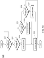
- FIG. 10 is a flowchart exemplifying a schematic operation in which the sensor unit 10, which is a master unit, activates a prescribed function.
- FIG. 11 is a flowchart exemplifying a schematic operation in which the sensor unit 10, which is a slave unit, activates a prescribed function.
- the control unit 60 executes a master unit function activation process S220 shown in FIG. 10 .
- the activation unit 64 determines whether an outside input signal is received (S221) based on a signal from the outside input unit 72. Step S221 is repeated until an outside signal is received.
- the activation unit 64 determines whether the outside input signal is a first outside input signal (S222). Whether the outside input signal is the first outside input signal is determined by using, for example, the period of the outside input signal, the amplitude (size) of the outside input signal, the pulse width thereof in the case where the outside input signal is a pulse wave, or a combination thereof as a criterion.
- Step S222 In the case where the determination result of Step S222 indicates that the received outside input signal is the first outside input signal, the activation unit 64 activates a first function in correspondence with the first outside input signal (S223).
- the activation unit 64 determines whether the outside input signal is a second outside input signal (S224). Whether the outside input signal is the second outside input signal is determined by using, for example, the period of the outside input signal, the amplitude (size) of the outside input signal, the pulse width thereof in the case where the outside input signal is a pulse wave, or a combination thereof as a criterion. Such criterion may be different from the criterion on whether the outside input signal is the first outside input signal.
- Step S224 In the case where the determination result of Step S224 indicates that the received outside input signal is the second outside input signal, the activation unit 64 activates a second function in correspondence with the second outside input signal (S225).
- the activation unit 64 determines whether the outside input signal is a third outside input signal (S226). Whether the outside input signal is the third outside input signal is determined by using, for example, the period of the outside input signal, the amplitude (size) of the outside input signal, the pulse width thereof in the case where the outside input signal is a pulse wave, or a combination thereof as a criterion. Such criterion may be different from the criteria on whether the outside input signal is the first outside input signal and whether the outside input signal is the second outside input signal.
- Step S226 indicates that the received outside input signal is the third outside input signal
- the activation unit 64 activates a third function in correspondence with the third outside input signal (S227).
- Step S226 indicates that the received outside input signal is not the third outside input signal
- the received outside input signal is considered as neither of the first outside input signal, the second outside input signal, and the third outside input signal for activating the prescribed functions. Accordingly, the control unit 60 ends the master unit function activation process S220 without taking any action.
- the signal output unit 65 transmits a light signal including the trigger signal to one of the sensor units 10 in the unit series, such as the sensor unit 10 on the right side, by using the light communication unit 50 (S228).
- the transmitted trigger signal is a pulse wave with the pulse width Wd4 in the case after Step S223, a pulse wave with the pulse width Wd5 in the case after Step S225, and is a pulse wave with the pulse width Wd6 in the case after Step S227.
- the control unit 60 executes a slave unit function activation process S240 shown in FIG. 11 .
- the activation unit 64 determines whether the light signal OS is received (S241) by using the light communication unit 50. Step S241 is repeated until the light signal OS is received.
- the activation unit 64 determines whether the light signal OS satisfies a first condition (S242).
- the first condition is, for example, that the light signal OS includes the pulse wave PW4 with the pulse width Wd4.
- Step S242 In the case where the determination result of Step S242 indicates that the received light signal OS satisfies the first condition, the activation unit 64 activates a first function in correspondence with the first condition (S243).
- Step S242 determines whether the received light signal OS satisfies a second condition (S244).
- the second condition is, for example, that the light signal OS includes the pulse wave PW5 with the pulse width Wd5.
- Step S244 In the case where the determination result of Step S244 indicates that the received light signal OS satisfies the second condition, the activation unit 64 activates a second function in correspondence with the second condition (S245).
- the activation unit 64 determines whether the light signal OS satisfies a third condition (S246).
- the third condition is, for example, that the light signal OS includes the pulse wave PW6 with the pulse width Wd6.
- Step S246 In the case where the determination result of Step S246 indicates that the received light signal OS satisfies the third condition, the activation unit 64 activates a third function in correspondence with the third condition (S247).
- Step S246 indicates that the received light signal OS does not satisfy the third condition
- the received light signal OS is considered as not including the trigger signal for activating a prescribed function. Accordingly, the control unit 60 ends the slave unit function activation process S240 without taking any action.
- the signal output unit 65 transmits the light signal OS including the trigger signal to one of the sensor units 10 in the unit series UL, such as the sensor unit 10 adjacent on the right, by using the light communication unit 50 (S248).
- the transmitted trigger signal is, for example, the fourth pulse wave PW4 with the pulse width Wd4 in the case after Step S243, the fifth pulse wave PW5 with the pulse width Wd5 in the case after Step S245, and the sixth pulse wave PW6 with the pulse width PW6 in the case after Step S247.
- the sensor unit 10 and the function activation method according to an embodiment of the invention activate the prescribed function, such as the sensitivity adjustment function, based on a signal from the outside, and outputs the trigger signal for activating the prescribed function to the outside based on the signal from the outside.
- the trigger signal can be transmitted to the adjacent sensor unit 10 in the unit series UL, such as the sensor unit 10 adjacent on the right.
- the prescribed function, such as the sensitivity adjustment function with respect to the sensor units 10 can be collectively activated, and the work load for activating the prescribed function, such as the sensitivity adjustment function, in each sensor unit 10 can be reduced.
- 10 Light projection unit; 10: Sensor unit; 11: Housing; 12: Display unit; 13: Operation unit; 14: Groove; 15: Electric cord; 16: Outbound optical fiber; 17: Inbound optical fiber; 18, 19: Light communication window; 21, 22: Sensor head; 30: Light projection unit; 31: Light projection element; 32: Light projection driving circuit; 40: Light receiving unit; 41: Light receiving element; 42: Signal amplification circuit; 50: Light communication unit; 51: Light emitting circuit; 52: Light emitting element; 53: Light receiving element; 54: Light receiving circuit; 55: Light emitting circuit; 56: Light emitting element; 57: Light receiving element; 58: Light receiving circuit; 60: Control unit; 61: Timing control unit; 62: A/D converter; 63: Determining unit; 64: Activation unit; 65: Signal output unit; 71: Storage unit; 72: Outside input unit; 73: Output unit; 99: DIN rail; 100: Sensor system; OS: Light signal; Pe1, Pe2, Pe3: Period; PW1: First pulse wave
Landscapes
- Physics & Mathematics (AREA)
- Engineering & Computer Science (AREA)
- General Physics & Mathematics (AREA)
- Electromagnetism (AREA)
- Computer Networks & Wireless Communication (AREA)
- Signal Processing (AREA)
- Radar, Positioning & Navigation (AREA)
- Remote Sensing (AREA)
- Arrangements For Transmission Of Measured Signals (AREA)
- Geophysics And Detection Of Objects (AREA)
- Electronic Switches (AREA)
Abstract
Description
- The invention relates to a sensor unit and a function activation method.
- Conventionally, as a sensor system, a sensor system having multiple sensor units combined to be able to transmit signals via a connector means is known. The sensor units respectively hold identification information, and set respective inherent identification numbers through signal transmission with one another. The respective sensor units operate after a delay time determined in correspondence with the respective identification numbers by using a synchronization signal transmitted at a prescribed period from a sensor unit having a specific type number among the sensor units as a start point. The delay time of each of the sensor units is determined so that an operation period is consistent with a prescribed period determined for each type information and different from the delay times of other sensor units having the same type information (see Patent Document 1). In the sensor system, the operation period arbitrarily determined for each type is realized, and interference among those of the same type is avoided.
- [Patent Document 1]
Japanese Laid-open No. 2014-96697 - Here, in a sensor system having multiple photoelectric sensor units, there is a need for collectively making sensitivity adjustment to the light receiving sensitivity or changing a threshold with respect to the photoelectric sensor units. In such case, the conventional sensor system adopts a configuration in which each sensor unit has a communication function, and the sensor system is provided with a communication unit capable of transmitting a command of sensitivity adjustment or threshold setting with respect to the respective sensor units.
- However, in the case where the communication unit is not provided as in the sensor system disclosed in
Patent Document 1, there is no way to collectively activate a function with respect to the sensor units. Therefore, it is necessary to perform an operation to activate the function for each of all the sensor units, and the work load becomes a burden. - Therefore, an objective of the invention is to provide a sensor unit and a function activation method capable of collectively activating a function with respect to multiple sensor units.
- A sensor unit according to an aspect of the invention is capable of forming a unit series by connecting multiple sensor units and includes: an activation unit, activating a prescribed function based on a signal from outside; and a signal output unit, outputting a trigger signal for activating the prescribed function to the outside based on the signal from the outside.
- According to the aspect, the prescribed function, such as the sensitivity adjustment function, is activated based on the signal from the outside, and the trigger signal for activating the prescribed function is output to the outside based on the signal from the outside. Accordingly, the trigger signal can be transmitted to the adjacent sensor unit in the unit series, such as the sensor unit adjacent on the right. Accordingly, with the respective sensor units successively transmitting the trigger signal, the prescribed function, such as the sensitivity adjustment function, with respect to the sensor units can be collectively activated, and the work load for activating the prescribed function, such as the sensitivity adjustment function, in each sensor unit can be reduced.
- According to the aspect, the sensor unit may further include a light communication unit capable of light signal transmission and reception. The signal output unit may transmit a light signal including the trigger signal to one of the sensor units in the unit series by using the light communication unit
- According to the aspect, the light signal including the trigger signal is transmitted to one of the sensor units in the unit series, such as the sensor unit adjacent on the right. Accordingly, a light signal used for another purpose, such as a synchronization signal, can be used to transmit the trigger signal.
- According to the aspect, at a time of a slave unit in the unit series, the activation unit may activate the prescribed function based on the trigger signal included in the light signal received from another sensor unit in the unit series by using the light communication unit.
- According to the aspect, at the time of the slave unit in the unit series, a light signal is received from the other side in the unit series, such as from the sensor unit adjacent on the left, and the prescribed function is activated based on the trigger signal included in the received light signal. Accordingly, the light signal used for another purpose, such as a synchronization signal, can be used, and, in the case of the slave unit in the unit series, the prescribed function can be easily activated.
- According to the aspect, the trigger signal may be represented as a pulse wave. At a time of a slave unit in the unit series, the activation unit may activate the prescribed function based on the width of the pulse wave included in the light signal received from another sensor unit in the unit series by using the light communication unit.
- According to the aspect, the prescribed function is activated based on the pulse width of the pulse wave included in the light signal. Accordingly, the trigger signal and signals other than the trigger signal in the light signal can be identified, and, in the light signal, the trigger signal and other signals, such as the synchronization signal can be easily used together.
- According to the aspect, the trigger signal may be represented as a pulse wave. At a time of a slave unit in the unit series, the activation unit may activate the prescribed function based on the width of the pulse wave included in the light signal received from another sensor unit in the unit series by using the light communication unit and the number of the pulse wave included in the light signal during a prescribed period.
- According to the aspect, the prescribed function is activated based on the pulse width of the pulse wave included in the light signal and the number of the pulse wave included in the light signal during the prescribed period. Accordingly, the trigger signal and signals other than the trigger signal in the light signal can be easily identified, and, in the light signal, the trigger signal and other signals, such as the synchronization signal can be even more easily used together.
- According to the aspect, the trigger signal may be represented as a pulse wave, and the prescribed function may include multiple functions. At a time of a slave unit in the unit series, the activation unit may activate one of the functions based on a width of the pulse wave included in the light signal received from another sensor unit in the unit series by using the light communication unit.
- According to the aspect, the prescribed function includes multiple functions, and one of the functions is activated based on the pulse width of the pulse wave included in the light signal. Accordingly, the functions included in the prescribed function can be easily chosen and activated.
- According to the aspect, the sensor unit may further include an outside input unit receiving an outside input signal. At a time of a master unit in the unit series, the activation unit activates the prescribed function based on the outside input signal.
- According to the aspect, at the time of the master unit in the unit series, the prescribed function is activated based on the outside input signal. Accordingly, by using the outside input signal, which is different from the case of the slave unit, the prescribed function can be easily activated in the case of the master unit in the unit series.
- According to the aspect, the sensor unit may further include a light projection unit, emitting light toward a target object; and a light receiving unit, configured to receive light to be able to detect a light receiving amount.
- According to the aspect, the sensor unit further includes a light projection unit, emitting light toward a target object; and a light receiving unit, configured to receive light to be able to detect a light receiving amount. Accordingly, a photoelectric sensor unit with which a prescribed function is collectively activated with respect to multiple photoelectric sensor units can be easily realized.
- In addition, a sensor system according to another aspect of the invention includes multiple sensor units.
- According to the aspect, multiple sensor units are included. Accordingly, the respective sensor units can collectively activate the prescribed function, and the work load for activating the prescribed function in each sensor unit can be reduced.
- In addition, a function activation method according to still another aspect of the invention is capable of forming a unit series by connecting multiple sensor units. The function activation method includes: an activation step of activating a prescribed function based on a signal from outside; and a signal output step of outputting a trigger signal for activating the prescribed function to the outside based on the signal from the outside.
- According to the aspect, the prescribed function, such as the sensitivity adjustment function, is activated based on the signal from the outside, and the trigger signal for activating the prescribed function is output to the outside based on the signal from the outside. Accordingly, the trigger signal can be transmitted to the adjacent sensor unit in the unit series, such as the sensor unit adjacent on the right. Accordingly, with the respective sensor units successively transmitting the trigger signal, the prescribed function, such as the sensitivity adjustment function, with respect to the sensor units can be collectively activated, and the work load for activating the prescribed function, such as the sensitivity adjustment function, in each sensor unit can be reduced.
- According to the aspect, the signal output step may include transmitting a light signal including the trigger signal to one of the sensor units in the unit series.
- According to the aspect, the light signal including the trigger signal is transmitted to one of the sensor units in the unit series, such as the sensor unit adjacent on the right. Accordingly, a light signal used for another purpose, such as a synchronization signal, can be used to transmit the trigger signal.
- According to the aspect, the activation step may include: at a time of a slave unit in the unit series, activating the prescribed function based on the trigger signal included in the light signal received from another sensor unit in the unit series.
- According to the aspect, at the time of the slave unit in the unit series, a light signal is received from the other side in the unit series, such as from the sensor unit adjacent on the left, and the prescribed function is activated based on the trigger signal included in the received light signal. Accordingly, the light signal used for another purpose, such as a synchronization signal, can be used, and, in the case of the slave unit in the unit series, the prescribed function can be easily activated.
- According to the aspect, the trigger signal may be represented as a pulse wave. The activation step may include: at a time of a slave unit in the unit series, activating the prescribed function based on a width of the pulse wave included in the light signal received from another sensor unit in the unit series
- According to the aspect, the prescribed function is activated based on the pulse width of the pulse wave included in the light signal. Accordingly, the trigger signal and signals other than the trigger signal in the light signal can be identified, and, in the light signal, the trigger signal and other signals, such as the synchronization signal can be easily used together.
- According to the aspect, the trigger signal may be represented as a pulse wave. The activation step may include: at a time of a slave unit in the unit series, activating the prescribed function based on a width of the pulse wave included in the light signal received from another sensor unit in the unit series and a number of the pulse wave included in the light signal during a prescribed period.
- According to the aspect, the prescribed function is activated based on the pulse width of the pulse wave included in the light signal and the number of the pulse wave included in the light signal during the prescribed period. Accordingly, the trigger signal and signals other than the trigger signal in the light signal can be easily identified, and, in the light signal, the trigger signal and other signals, such as the synchronization signal can be even more easily used together.
- According to the aspect, the trigger signal may be represented as a pulse wave, and the prescribed function may include multiple functions. The activation step may include: at a time of a slave unit in the unit series, activating one of the functions based on a width of the pulse wave included in the light signal received from another sensor unit in the unit series.
- According to the aspect, the prescribed function includes multiple functions, and one of the functions is activated based on the pulse width of the pulse wave included in the light signal. Accordingly, the functions included in the prescribed function can be easily chosen and activated.
- According to the aspect, the activation step may include: at a time of a master unit in the unit series, activating the prescribed function based on an outside input signal.
- According to the aspect, at the time of the master unit in the unit series, the prescribed function is activated based on the outside input signal. Accordingly, by using the outside input signal, which is different from the case of the slave unit, the prescribed function can be easily activated in the case of the master unit in the unit series.
- According to the invention, the functions of multiple sensor units can be activated collectively.
-
-
FIG. 1 is a diagram illustrating a schematic configuration of a sensor system according to an embodiment of the invention. -
FIG. 2 is a perspective view exemplifying the appearance of a sensor unit shown inFIG. 1 . -
FIG. 3 is a block diagram exemplifying a schematic internal configuration of the sensor unit shown inFIG. 2 . -
FIG. 4 is a flowchart exemplifying a schematic operation in which a sensor unit recognizes a channel number. -
FIG. 5 is a diagram exemplifying binary data which a sensor unit of a master unit transmits. -
FIG. 6 is a diagram exemplifying binary data which a sensor unit as a slave unit transmits. -
FIG. 7 is a waveform diagram exemplifying a light signal which a light communication unit shown inFIG. 3 transmits and receives. -
FIG. 8 is a table exemplifying a relationship between a pulse wave included in the light signal of the light communication unit shown inFIG. 3 and a use thereof. -
FIG. 9 is a perspective view exemplifying a schematic configuration of a conveyance mechanism in which a sensor head of a sensor unit is disposed. -
FIG. 10 is a flowchart exemplifying a schematic operation in which a sensor unit, as a master unit, activates a prescribed function. -
FIG. 11 is a flowchart exemplifying a schematic operation in which a sensor unit, as a slave unit, activates a prescribed function. - The embodiments of the invention will be described in the following. In the descriptions of the following drawings, like or similar parts are represented by like or similar symbols. However, the drawings are merely schematic. Therefore, specific dimensions should be determined in light of the following explanation. In addition, it goes without saying that the drawings include parts having different dimensional relationships and ratios from each other. Furthermore, the technical scope of the invention should not be construed as limited to the embodiment.
- First of all, referring to
FIGs. 1 and2 , an example of the appearance of a sensor unit according to an embodiment of the invention will be described.FIG. 1 is a diagram illustrating a schematic configuration of asensor system 100 according to an embodiment of the invention.FIG. 2 is a perspective view exemplifying the appearance of asensor unit 10 shown inFIG. 1 . - As shown in
FIG. 1 , thesensor system 100 includesmultiple sensor units 10. Each of thesensor units 10 is installed to aDIN rail 99, and thesensor units 10 are arranged to be adjacent to one another or provided with a fine gap therebetween. Therefore, thesensor units 10 form a sensor row UL configured by n (n being 2 or more) sensor units SU1 to SUn. - The
sensor unit 10 is, for example, an optical fiber type photoelectric sensor unit. As shown inFIG. 2 , thesensor unit 10 includes ahousing 11 in a substantially rectangular parallelepiped shape. On the upper surface of thehousing 11, adisplay unit 12 and anoperation unit 13 are provided. Thedisplay unit 12 is configured as including a display with seven segments, for example. Theoperation unit 13 is configured as having multiple buttons, switches, etc., for example. On the lower surface of thehousing 11, agroove 14 for attachment to theDIN rail 99 is formed. - An
electric cord 15 is pulled out of the rear surface of thehousing 11. Theelectric cord 15 is, for example, connected with a control machine such as a programmable logic controller (PLC), etc. In addition, from the front surface of thehousing 11, an outboundoptical fiber cable 16 and an inboundoptical fiber cable 17 are pulled out. The tip of the outboundoptical fiber 16 is connected with asensor head 21, and the tip of the inboundoptical fiber 17 is connected with thesensor head 22. - In addition, on the left side surface of the
housing 11, alight communication window 18 is formed, and on the right side surface of the housing, which is a surface on the positive side of the X-axis inFIG. 2 , alight communication window 19 is formed. InFIG. 2 , thelight communication windows light communication windows - As shown in
FIG. 1 , when thesensor units 10 are arranged into a row to form the unit series UL, for example, thelight communication window 19 of the sensor unit SU1 and thelight communication window 18 of the sensor unit SU2 are opposite to each other. Accordingly, as will be described in the following, it is possible to communicate (occasionally referred to as light communication in the following) via light signals in two directions between theadjacent sensor units 10. - Then, referring to
FIG. 3 , an example of the internal configuration of the sensor unit according to an embodiment of the invention is described.FIG. 3 is a block diagram exemplifying a schematic internal configuration of thesensor unit 10 shown inFIG. 2 . - As shown in
FIG. 3 , in thesensor unit 10, alight projection unit 30, alight receiving unit 40, alight communication unit 50, acontrol unit 60, astorage unit 71, theoperation unit 13, anoutside input unit 72, thedisplay unit 12, and anoutput unit 73 are provided. - The
light projection unit 30 emits light toward a target object (not shown). Thelight projection unit 30, for example, includes alight projection element 31 and a lightprojection driving circuit 32. Thelight projection element 31 is a light emitting diode, for example. Alternatively, thelight projection element 31 may also be a light emitting element such as a light emitting diode, a laser diode. The lightprojection driving circuit 32 drives thelight projection element 31. Specifically, the lightprojection driving circuit 32 outputs a driving signal to thelight projection element 31 based on a control signal input from thecontrol unit 60. Thelight projection element 31 is driven by the driving signal to emit light. - The
light receiving unit 40 is one in which multiple pixels respectively receive light to obtain light receiving distribution signals to be described afterwards. Thelight receiving unit 40, for example, includes alight receiving element 41 and asignal amplification circuit 42. Thelight receiving element 41 is a photodiode, for example. Alternatively, thelight receiving element 41 may also be an image capturing element, such as a complementary MOSFET (CMOS) image sensor, a charge coupled device (CMD) image sensor, etc. An electrical signal obtained through light reception by thelight receiving element 41 is amplified by thesignal amplification circuit 42. Thesignal amplification circuit 42 outputs the amplified electrical signal to thecontrol unit 60. - The
light communication unit 50, as shown inFIG. 1 , is configured between theadjacent sensor units 10 to enable light communication in two directions. Thelight communication unit 50 includes alight emitting circuit 51, alight emitting element 52, alight receiving element 53, and alight receiving circuit 54 for performing light communication with thesensor unit 10 adjacent on the left when viewed from itself and alight emitting circuit 55, alight emitting element 56, alight receiving element 57, and alight receiving circuit 58 for performing light communication with the sensor unit adjacent on the right when viewed from itself. - The
light emitting element 52 and thelight receiving element 53 are disposed inside thehousing 11 so as to be opposite to thelight communication window 18 shown inFIG. 2 . Thelight emitting element 52 is, for example, a light emitting diode that emits infrared light, for example, and thelight receiving element 53 is, for example, a photodiode. The control signal from thecontrol unit 60 is input to thelight receiving circuit 51. Thelight emitting circuit 51 makes thelight emitting element 52 emit infrared light based on the control signal. Thelight receiving element 53 receives infrared light from thesensor unit 10 arranged to be adjacent on the left inFIG. 1 , for example. An electrical signal (referred to as "light receiving signal") indicating a light receiving amount thereof is output to thecontrol unit 60 via thelight receiving circuit 54. - In addition, the
light emitting element 56 and thelight receiving element 57 are disposed inside thehousing 11 so as to be opposite to thelight communication window 19 shown inFIG. 2 . Thelight emitting element 56 is, for example, a light emitting diode that emits infrared light, for example, and thelight receiving element 57 is, for example, a photodiode. The control signal from thecontrol unit 60 is input to thelight receiving circuit 55. Thelight emitting circuit 55 makes thelight emitting element 56 emit infrared light based on the control signal. Thelight receiving element 57 receives the infrared light from thesensor unit 10 arranged to be adjacent on the right inFIG. 1 , for example. The light receiving signal indicating the light receiving amount thereof is output to thecontrol unit 60 via thelight receiving circuit 58. - The
control unit 60 is configured to control the operations of the respective units of thesensor unit 10. In addition, thecontrol unit 60 is configured to realize the respective functions to be described afterwards by executing a program stored in thestorage unit 71, etc. Thecontrol unit 60 is configured as including a microprocessor, such as a central processing unit (CPU). - The
control unit 60 includes atiming control unit 61 and an analog-to-digital (A/D)converter 62. Thetiming control unit 61 is configured so as to control the timing of the light emitted from thelight projection unit 30 based on a synchronization signal included in the light receiving signal. Specifically, thetiming control unit 61 outputs the control signal to the lightprojection driving circuit 32 at a prescribed timing by using the synchronization signal as a start point. The A/D converter 62 samples, quantizes, and encodes the electrical signal input from thesignal amplification circuit 42 of thelight receiving unit 40 to convert the electrical signal into a digital signal. Thecontrol unit 60 is configured so as to determine whether there is a target object by comparing the digital signal with a prescribed threshold. In addition, thecontrol unit 60 is configured so as to generate a binary signal, in which "1" stands for the case where there is a corresponding object and "0" stands for the case where there is no target object, according to the determination result, and output the binary signal to the outside via theoutput unit 73. - In addition, the
control unit 60, as a functional configuration thereof, includes a determiningunit 63, andactivation unit 64, and asignal output unit 65, for example. - The determining
unit 63 is configured so as to determine whether thesensor unit 10 of its own is a master unit (referred to as "master") or a slave unit (referred to as "slave") in the unit series UL. The determiningunit 63 determines whether thesensor unit 10 is a master unit or a slave unit by recognizing the channel number by using thelight communication unit 50, for example. - The
activation unit 64 is configured so as to activate a prescribed function based on a signal from the outside. The signal from the outside is, for example, a light signal received by using thelight communication unit 50, an outside input signal received by using anoutside input unit 72 to be described afterwards, etc. In addition, the prescribed function is, for example, a sensitivity adjustment function for adjusting the sensitivity of the light receiving signal of thelight receiving unit 40 for detecting the target object, a setting function for setting a setting value of various settings of thesensor unit 10. The prescribed function is not limited to one, but may also be multiple. In the case where there are multiple prescribed functions, a signal from the outside for activating one of the functions may be different from a signal from the outside for activating another function. Theactivation unit 64 may also generate and output a control signal, for example, to activate the prescribed function. - The
signal output unit 65 is configured so as to output a trigger signal for activating the prescribed function to the outside based on the signal from the outside. The trigger signal is, for example, represented by a pulse wave having a prescribed amplitude (referred to as "pulse width" in the following). The type of the pulse wave is not particularly limited, and the pulse wave may be, for example, a sine wave, a square wave, a triangular wave, a sawtooth wave, etc. In addition, the pulse wave may be transmitted at a prescribed period. - More specifically, the
signal output unit 65 is configured so as to transmit a light signal including the trigger signal to one of thesensor units 10 in the unit series UL, such as thesensor unit 10 adjacent on the right, by using thelight communication unit 50. Accordingly, a light signal used for another purpose, such as a synchronization signal, can be used to transmit the trigger signal. - The
activation unit 64 is configured to be different in the case of the master unit and the case of the slave unit in the unit series UL. Specifically, at the time of the slave unit in the unit series UL, theactivation unit 64 receives a light signal from the other side in the unit series UL, such as from thesensor unit 10 adjacent on the left, by using thelight communication unit 50, and activates the prescribed function based on the trigger signal included in the received light signal. Accordingly, a light signal used for another purpose, such as a synchronization signal, can be used, and, in the case of the slave unit in the unit series UL, the prescribed function can be easily activated. - Meanwhile, at the time of the master unit in the unit series UL, the
activation unit 64 activates the prescribed function based on the outside input signal received by theoutside input unit 72 to be described in the following. Accordingly, by using the outside input signal, which is different from the case of the slave unit, the prescribed function can be easily activated in the case of the master unit in the unit series UL. - The
storage unit 71 is configured to store a program, data, etc. Specifically, thestorage unit 71 stores a program executed by thecontrol unit 60 and data such as a set value, etc. Thestorage unit 71 is configured to include a memory such as a read only memory (ROM), a random access memory (RAM), a buffer memory etc. - The
external input unit 72 is configured so as to receive the outside input signal from the outside of the sensor unit 110. The outside input signal is an electrical signal, for example. The type of the outside input signal which theoutside input unit 72 is able to receive is not limited to one type, but may include multiple types. Theoutside input unit 72 outputs the received outside input signal to thecontrol unit 60. - The
output unit 73 is a unit for outputting a signal to the outside of thesensor unit 10. The signal output by theoutput unit 73 is, for example, an electrical signal. The type of the signal output by theoutput unit 73 is not limited to one, but may include multiple types. Theoutput unit 73 outputs a signal based on the control signal input from thecontrol unit 60. - The
operation unit 13 is a unit for inputting information to thesensor unit 10. For example, when a user operates a button, a switch, etc., of theoperation unit 13, thecontrol unit 60 generates data in correspondence with the operation. Accordingly, information is input to thesensor unit 10. - The
display unit 12 is a unit for outputting information of thesensor unit 10. Thedisplay unit 12, for example, displays the determination result on whether there is a target object by using a numeral, text, a symbol, etc. In addition, thedisplay unit 12 displays contents set/to be set in thesensor unit 10, such as a value, an ON/OFF state, an item name, etc., by using a numeral, text, a symbol, etc. Accordingly, the information of thesensor unit 10 is input. - Then, referring to
FIGs. 4 to 6 , an operation in which a sensor unit recognizes a channel number according to an embodiment of the invention is described.FIG. 4 is a flowchart exemplifying a schematic operation in which thesensor unit 10 recognizes the channel number.FIG. 5 is a diagram exemplifying binary data which thesensor unit 10 as a master unit transmits.FIG. 6 is a diagram exemplifying binary data which thesensor unit 10 as a slave unit transmits. - As shown in
FIG. 4 , firstly, thecontrol unit 60 sets both the input port and the output port of thelight communication unit 50 to a general input/output allocation, and then sets the output as ON during a prescribed period to output light (S201). Accordingly, infrared light from thelight emitting element 56 is emitted in the prescribed period, for example. - Then, the determining
unit 63 determines whether infrared light is received by using thelight receiving element 53, for example, after the prescribed period from light starting being output (S202). - In the case where the determination result of Step 202 is that no infrared light is received, it is considered that a
sensor unit 10 is not present on the upstream side, such as the adjacent left side, in the unit series UL. Accordingly, the determiningunit 63 recognizes itself as in a master unit in the unit series UL (S203). That is, the determiningunit 63 recognizes the channel number as "1". - In the case where the determination result of Step 202 is that infrared light is received, it is considered that a
sensor unit 10 is present on the upstream side, such as the adjacent left side, in the unit series UL. Accordingly, the determiningunit 63 recognizes itself as in a slave unit in the unit series UL (S204). That is, the determiningunit 63 recognizes the channel number as a number other than "1". - After a further prescribed period, the
control unit 60 switches the input port and the output port of thelight communication unit 50 to a universal asynchronous receiver transmitter (UART) allocation, and then, in the case of the master unit, transmits binary data exemplified inFIG. 5 to theadjacent sensor unit 10, such as thesensor unit 10 adjacent on the right (S205). In the case where thesensor unit 10 is a slave unit, thecontrol unit 60 does not perform Step S205. The binary data takes into consideration a difference in the timing at which power is turned on, and is output repeatedly for a predetermined number of times or more. - As shown in
FIG. 5 , by inputting data "0x01" as "self CH number", the channel number of the master unit being achannel 1 is expressed. By inputting data "0x01" as "number of sensor type A", it is expressed that onesensor unit 10 of type A is recognized. That is, the type of the master unit sending the binary data ofFIG. 5 is "A". For example, in the case where the type of the master unit is "B", data "0x00" is input as "number of sensor type A", whereas data "0x01" is input as "number of sensor type B". The type information expressing the type of thesensor unit 10 is held in eachsensor unit 10. - The number of each type of the
sensor unit 10 also expresses an order m (m being a positive integer) of each type of thesensor unit 10. By inputting data "0x01" as "number of sensor type A", it is expressed that the order m in a group of thesensor units 10 of the type A is "1 ". - "Setting the general input/output allocation" above means "not setting the UART allocation".
- Referring to
FIG. 4 again, in thesensor unit 10 receiving the binary data, i.e., in thesensor unit 10 as a slave unit, thecontrol unit 60 transmits the binary data exemplified inFIG. 6 to theadjacent sensor unit 10, such as thesensor unit 10 adjacent on the right, by using the light communication unit 50 (S206). In the case where thesensor unit 10 is a master unit, thecontrol unit 60 does not perform Step S206. - Since the data "0x01" has been input to "self CH number" of the received binary data, the
control unit 60 of thesensor unit 10 receiving the binary data recognizes the channel number of itself as "2". That is, the channel number of itself is recognized as a number greater by 1 than the channel number expressed by the "self CH number" of the received binary data. In the binary data shown inFIG. 6 , the channel number is incremented by 1 to express the channel number as "2", and data "0x02" is input as the "self CH number". Accordingly, in the case where data "0x05" has been input to the "self CH number" of the received binary data, data "0x06" is input to the "self CH number" in the binary data to be transmitted. - Also, in the example of
FIG. 6 , since the type of thesensor unit 10 which receives the binary data from the master unit is "A", "number of sensor type A" is incremented by 1 and data "0x02" is input. That is, it is recognized that the order is "2" in the group of thesensor units 10 of the type A. - Referring to
FIG. 4 again, after Step S206, thecontrol unit 60 ends a channel number recognition process S200. - In this way, binary data is sent one after another by the
sensor unit 10. Eachsensor unit 10 recognizes a number greater by 1 than the channel number expressed by the "self CH number" of the received binary data as the channel number. - Then, referring to
FIGs. 7 and8 , an example of the light communication of a sensor unit according to an embodiment of the invention will be described.FIG. 7 is a waveform diagram exemplifying a light signal OS which thelight communication unit 50 shown inFIG. 3 transmits and receives.FIG. 8 is a table exemplifying a relationship between a pulse wave included in the light signal OS of thelight communication unit 50 shown inFIG. 3 and a use thereof. - As shown in the upper part of
FIG. 7 , in a normal situation where the prescribed function is not activated, the light signal OS, for example, includes three types of pulse waves, i.e., a first pulse wave PW1, a second pulse wave PW2, and a third pulse wave PW3. The first pulse wave PW1 has a pulse width Wd1 and is a wave with a period Pe1. The second pulse wave PW2 has a pulse width Wd2 greater than the pulse width Wd1 of the first pulse wave PW1 (pulse width Wd1 < pulse width Wd2), and is a wave with a period Pe2 longer than the period Pe1 of the first pulse wave PW1 (period Pe1 < period Pe2). The third pulse wave PW3 has a pulse width Wd3 greater than the pulse width Wd2 of the second pulse wave PW2 (pulse width Wd2 < pulse width Wd3), and is a wave with a period Pe3 longer than the period Pe2 of the second pulse wave PW2 (period Pe2 < period Pe3). - As shown in the lower part of
FIG. 7 , in a situation where the prescribed function is activated, the light signal OS, for example, includes a fourth pulse wave PW4 in addition to the first pulse wave W1 and the second pulse wave PW2. The fourth pulse wave PW4 has a pulse width Wd4 greater than the pulse width Wd3 of the third pulse wave PW3 (pulse width Wd3 < pulse width Wd4), and is a wave with the same period as the period Pe3 of the third pulse wave PW3. - According to the embodiment, in the lower part of
FIG. 4 , while an example in which the light signal OS includes the fourth pulse wave PW4 in place of the third pulse wave PW3 is shown, the invention is not limited thereto. At the time when the prescribed function is activated, the light signal OS may also include the third pulse wave PW3 and the fourth pulse wave PW4. - The
control unit 60 uses a pulse wave in a different purpose in correspondence with the pulse width of the pulse wave included in the received light signal OS. As shown inFIG. 5 , when receiving a pulse wave with the pulse width Wd1 or more, such as the first pulse wave PW1, thecontrol unit 60 uses the pulse wave for the synchronization of the measurement timings by thelight projection unit 30 and thelight receiving unit 40. In addition, when receiving a pulse wave with the pulse width Wd2 or more, such as the second pulse wave PW2, thecontrol unit 60 further uses the pulse wave as the timing of outputting measurement values by thelight projection unit 30 and thelight receiving unit 40 and as the timing for preventing thesensor units 10 of types "A" and "B" from interfering with each other. Moreover, when receiving a pulse wave with the pulse width Wd3 or more, such as the third pulse wave PW3, thecontrol unit 60 further uses the pulse wave as the timing for preventing thesensor units 10 of types "C" and "D" from interfering with each other. - Furthermore, the
activation unit 64 uses the pulse wave included in the light signal OS as the trigger signal activating the prescribed function. That is, at the time of the slave unit in the unit series UL, theactivation unit 64 receives the light signal OS from the other side in the unit series UL, such as from thesensor unit 10 adjacent on the left, by using thelight communication unit 50, and activates a prescribed process based on the pulse width of the pulse wave included in the light signal OS. Specifically, theactivation unit 64 activates the sensitivity adjustment function which adjusts the sensitivity for detecting the target object when receiving a pulse wave with the pulse width Wd4, i.e., the fourth pulse wave PW4. In the sensitivity adjustment function, thecontrol unit 60 changes the threshold used at the time of determining whether there is a target object. Accordingly, by activating the prescribed function based on the pulse width of the pulse wave included in the light signal OS, the trigger signal and signals other than the trigger signal in the light signal OS can be identified, and, in the light signal OS, the trigger signal and other signals, such as the synchronization signal, can be easily used together. - Moreover, at the time of the slave unit in the unit series UL, the
activation unit 64 may receive the light signal OS from the other side in the unit series UL, such as from thesensor unit 10 adjacent on the left, by using thelight communication unit 50, and activate a prescribed process based on the pulse width of the pulse wave included in the light signal OS and the number of pulse waves. Specifically, theactivation unit 64 activates the sensitivity adjustment function when receiving the fourth pulse wave PW4 with the pulse width Wd4 thrice during a period that is three times the period Pe3 of the fourth pulse wave PW4. Accordingly, by activating the prescribed function based on the pulse width of the pulse wave included in the light signal OS and the number of pulse waves included in the light signal OS during a prescribed period, the trigger signal and signals other than the trigger signal in the light signal OS can be easily identified, and, in the light signal OS, the trigger signal and other signals, such as the synchronization signal, can be used together even more easily. - While
FIG. 7 illustrates an example in which theactivation unit 64 activates the sensitivity adjustment function when receiving the fourth pulse wave PW4 with the pulse width Wd4 thrice, the invention is not limited thereto. For example, theactivation unit 64 may also activate the sensitivity adjustment function when receiving the fourth pulse wave PW4 with the pulse width Wd4 twice or four times. In such case, theactivation unit 64 activates the sensitivity adjustment function when not receiving the fourth wave PW4 with the pulse width Wd4 during the period three times the period Pe3 of the fourth pulse PW3 after receiving the fourth pulse wave PW4 with the pulse width Wd4 twice or four times. - In addition, the prescribed function activated by the
activation unit 64 is not limited to one function, but may also include multiple functions. In such case, for example, theactivation unit 64 activates a first setting function which switches various settings to first setting values when receiving a fifth pulse wave PW5. The fifth pulse wave PW5 has a pulse width Wd5 greater than the pulse width Wd4 of the fourth pulse wave PW4 (pulse width Wd4 < pulse width Wd5), and is a wave with the same period as the period Pe3 of the third pulse wave PW3. Alternatively, theactivation unit 64 activates a first setting function which switches various settings to second setting values when receiving a sixth pulse wave PW6. The sixth pulse wave PW6 has a pulse width Wd6 greater than the pulse width Wd5 of the fifth pulse wave PW5 (pulse width Wd5 < pulse width Wd6), and is a wave with the same period as the period Pe3 of the third pulse wave PW3. Accordingly, the prescribed function includes multiple functions, and by activating one of the multiple functions based on the pulse width of the pulse wave included in the light signal OS, the functions included in the prescribed function can be easily selected and activated. - Then, referring to
FIG. 9 , an application example of a case in which a sensor unit according to an embodiment of the invention activates a prescribed function is described.FIG. 9 is a perspective view exemplifying a schematic configuration of a conveyance mechanism CM in which sensor heads 21 and 22 of thesensor unit 10 are disposed. - As shown in
FIG. 9 , the conveyance mechanism CM is configured so as to move a substrate SUB in a direction from the left ofFIG. 9 to the right, for example, by rotating a roller. In each of thesensor units 10 forming the unit series UL shown inFIG. 1 , thesensor head 21 is disposed on a rail on the near side inFIG. 9 , and the sensor head 23 is disposed on a rail on the back side inFIG. 9 . With the light emitted from thesensor head 21 being shielded by the substrate SUB and not incident to thesensor head 22, thesensor unit 10 detects that the substrate SUB, which is the target object, is passing through. - The conveyance mechanism CM is configured to be able to convey multiple types of the substrates SUB. When the substrates SUB of different sizes are being transported, the conveyance mechanism CM moves the rail on the front side in the direction of the arrow sign shown in
FIG. 9 , and the distance between the rail on the front side and the rail on the back side is able to vary. - When the distance between the rails is changed, since the distance between the
sensor head 21 and thesensor head 22 is also changed, it becomes necessary to adjust each of thesensor units 10 to the sensitivity corresponding to the distance between the rails of the conveyance mechanism CM. - In such case, the
sensor unit 10 according to the embodiment activates the prescribed function, such as the sensitivity adjustment function, based on a signal from the outside, and outputs a trigger signal for activating the prescribed function to the outside based on the signal from the outside. Accordingly, the trigger signal can be transmitted to theadjacent sensor unit 10 in the unit series UL, such as thesensor unit 10 adjacent on the right. Accordingly, with therespective sensor units 10 successively transmitting the trigger signal, the prescribed function, such as the sensitivity adjustment function, with respect to thesensor units 10 can be collectively activated, and the work load for activating the prescribed function, such as the sensitivity adjustment function, in eachsensor unit 10 can be reduced. - Then, referring to
FIGs. 10 and11 , an operation performed when a sensor unit according to an embodiment of the invention activates a prescribed function is described.FIG. 10 is a flowchart exemplifying a schematic operation in which thesensor unit 10, which is a master unit, activates a prescribed function.FIG. 11 is a flowchart exemplifying a schematic operation in which thesensor unit 10, which is a slave unit, activates a prescribed function. - When the
sensor unit 10 itself is determined as the master unit in the unit series UL by the determiningunit 63, for example, thecontrol unit 60 executes a master unit function activation process S220 shown inFIG. 10 . - Firstly, the
activation unit 64 determines whether an outside input signal is received (S221) based on a signal from theoutside input unit 72. Step S221 is repeated until an outside signal is received. - In the case where an outside input signal is received based on the determination result of Step S221, the
activation unit 64 determines whether the outside input signal is a first outside input signal (S222). Whether the outside input signal is the first outside input signal is determined by using, for example, the period of the outside input signal, the amplitude (size) of the outside input signal, the pulse width thereof in the case where the outside input signal is a pulse wave, or a combination thereof as a criterion. - In the case where the determination result of Step S222 indicates that the received outside input signal is the first outside input signal, the
activation unit 64 activates a first function in correspondence with the first outside input signal (S223). - Meanwhile, in the case where the determination result of Step S222 indicates that the received outside input signal is not the first outside input signal, the
activation unit 64 determines whether the outside input signal is a second outside input signal (S224). Whether the outside input signal is the second outside input signal is determined by using, for example, the period of the outside input signal, the amplitude (size) of the outside input signal, the pulse width thereof in the case where the outside input signal is a pulse wave, or a combination thereof as a criterion. Such criterion may be different from the criterion on whether the outside input signal is the first outside input signal. - In the case where the determination result of Step S224 indicates that the received outside input signal is the second outside input signal, the
activation unit 64 activates a second function in correspondence with the second outside input signal (S225). - Meanwhile, in the case where the determination result of Step S224 indicates that the received outside input signal is not the second outside input signal, the
activation unit 64 determines whether the outside input signal is a third outside input signal (S226). Whether the outside input signal is the third outside input signal is determined by using, for example, the period of the outside input signal, the amplitude (size) of the outside input signal, the pulse width thereof in the case where the outside input signal is a pulse wave, or a combination thereof as a criterion. Such criterion may be different from the criteria on whether the outside input signal is the first outside input signal and whether the outside input signal is the second outside input signal. - In the case where the determination result of Step S226 indicates that the received outside input signal is the third outside input signal, the
activation unit 64 activates a third function in correspondence with the third outside input signal (S227). - Meanwhile, in the case where the determination result of Step S226 indicates that the received outside input signal is not the third outside input signal, the received outside input signal is considered as neither of the first outside input signal, the second outside input signal, and the third outside input signal for activating the prescribed functions. Accordingly, the
control unit 60 ends the master unit function activation process S220 without taking any action. - After Step S223, Step S225, and Step S227, the
signal output unit 65 transmits a light signal including the trigger signal to one of thesensor units 10 in the unit series, such as thesensor unit 10 on the right side, by using the light communication unit 50 (S228). The transmitted trigger signal is a pulse wave with the pulse width Wd4 in the case after Step S223, a pulse wave with the pulse width Wd5 in the case after Step S225, and is a pulse wave with the pulse width Wd6 in the case after Step S227. - After Step S228, the
control unit 60 ends the master unit function activation process S220. - In addition, when the
sensor unit 10 itself is determined as the slave unit in the unit series UL by the determiningunit 63, for example, thecontrol unit 60 executes a slave unit function activation process S240 shown inFIG. 11 . - Firstly, the
activation unit 64 determines whether the light signal OS is received (S241) by using thelight communication unit 50. Step S241 is repeated until the light signal OS is received. - In the case where the light signal OS is received based on the determination result of Step S241, the
activation unit 64 determines whether the light signal OS satisfies a first condition (S242). The first condition is, for example, that the light signal OS includes the pulse wave PW4 with the pulse width Wd4. - In the case where the determination result of Step S242 indicates that the received light signal OS satisfies the first condition, the
activation unit 64 activates a first function in correspondence with the first condition (S243). - Meanwhile, in the case where the determination result of Step S242 indicates that the received light signal OS does not satisfy the first condition, the
activation unit 64 determines whether the light signal OS satisfies a second condition (S244). The second condition is, for example, that the light signal OS includes the pulse wave PW5 with the pulse width Wd5. - In the case where the determination result of Step S244 indicates that the received light signal OS satisfies the second condition, the
activation unit 64 activates a second function in correspondence with the second condition (S245). - Meanwhile, in the case where the determination result of Step S244 indicates that the received light signal OS does not satisfy the second condition, the
activation unit 64 determines whether the light signal OS satisfies a third condition (S246). The third condition is, for example, that the light signal OS includes the pulse wave PW6 with the pulse width Wd6. - In the case where the determination result of Step S246 indicates that the received light signal OS satisfies the third condition, the
activation unit 64 activates a third function in correspondence with the third condition (S247). - Meanwhile, in the case where the determination result of Step S246 indicates that the received light signal OS does not satisfy the third condition, the received light signal OS is considered as not including the trigger signal for activating a prescribed function. Accordingly, the
control unit 60 ends the slave unit function activation process S240 without taking any action. - After Step S243, Step S245, and Step S247, the
signal output unit 65 transmits the light signal OS including the trigger signal to one of thesensor units 10 in the unit series UL, such as thesensor unit 10 adjacent on the right, by using the light communication unit 50 (S248). The transmitted trigger signal is, for example, the fourth pulse wave PW4 with the pulse width Wd4 in the case after Step S243, the fifth pulse wave PW5 with the pulse width Wd5 in the case after Step S245, and the sixth pulse wave PW6 with the pulse width PW6 in the case after Step S247. - After Step S228, the
control unit 60 ends the slave unit function activation process S240. - An exemplary embodiment of the invention has been described above. The
sensor unit 10 and the function activation method according to an embodiment of the invention activate the prescribed function, such as the sensitivity adjustment function, based on a signal from the outside, and outputs the trigger signal for activating the prescribed function to the outside based on the signal from the outside. Accordingly, the trigger signal can be transmitted to theadjacent sensor unit 10 in the unit series UL, such as thesensor unit 10 adjacent on the right. Accordingly, with therespective sensor units 10 successively transmitting the trigger signal, the prescribed function, such as the sensitivity adjustment function, with respect to thesensor units 10 can be collectively activated, and the work load for activating the prescribed function, such as the sensitivity adjustment function, in eachsensor unit 10 can be reduced. - The embodiments described above are for facilitating the understanding of the invention, and are not for limiting and interpreting the invention. Each element included in the embodiment and its arrangement, material, condition, shape, size, and the like are not limited to those exemplified, and can be changed as appropriate. In addition, the configurations shown in different embodiments can be partially replaced or combined.
-
- 1. A sensor unit (10), capable of forming a unit series by connecting a plurality of sensor units. The sensor unit includes: an activation unit (64), activating a prescribed function based on a signal from outside; and a signal output unit (65), outputting a trigger signal for activating the prescribed function to the outside based on the signal from the outside.
- 10. A function activation method for a sensor unit (10) capable of forming a unit series by connecting a plurality of sensor units. The function activation method includes: an activation step of activating a prescribed function based on a signal from outside; and a signal output step of outputting a trigger signal for activating the prescribed function to the outside based on the signal from the outside.
- 10: Light projection unit; 10: Sensor unit; 11: Housing; 12: Display unit; 13: Operation unit; 14: Groove; 15: Electric cord; 16: Outbound optical fiber; 17: Inbound optical fiber; 18, 19: Light communication window; 21, 22: Sensor head; 30: Light projection unit; 31: Light projection element; 32: Light projection driving circuit; 40: Light receiving unit; 41: Light receiving element; 42: Signal amplification circuit; 50: Light communication unit; 51: Light emitting circuit; 52: Light emitting element; 53: Light receiving element; 54: Light receiving circuit; 55: Light emitting circuit; 56: Light emitting element; 57: Light receiving element; 58: Light receiving circuit; 60: Control unit; 61: Timing control unit; 62: A/D converter; 63: Determining unit; 64: Activation unit; 65: Signal output unit; 71: Storage unit; 72: Outside input unit; 73: Output unit; 99: DIN rail; 100: Sensor system; OS: Light signal; Pe1, Pe2, Pe3: Period; PW1: First pulse wave; PW2: Second pulse wave; PW3: Third pulse wave; PW4: Fourth pulse wave; PW5: Fifth pulse wave; PW6: Sixth pulse wave; S200: Channel number recognition process; S220: Parent apparatus function activation process; S240: slave unit function activation process; SUB: Substrate; UL: Unit series; Wd1, Wd2, Wd3, Wd4, Wd5, Wd6: Pulse width.
Claims (16)
- A sensor unit, capable of forming a unit series by connecting a plurality of sensor units, the sensor unit comprising:an activation unit, activating a prescribed function based on a signal from outside; anda signal output unit, outputting a trigger signal for activating the prescribed function to the outside based on the signal from the outside.
- The sensor unit as claimed in claim 1, further comprising a light communication unit capable of light signal transmission and reception,
wherein the signal output unit transmits a light signal comprising the trigger signal to one of the sensor units in the unit series by using the light communication unit. - The sensor unit as claimed in claim 2, wherein at a time of a slave unit in the unit series, the activation unit activates the prescribed function based on the trigger signal comprised in the light signal received from another sensor unit in the unit series by using the light communication unit.
- The sensor unit as claimed in claim 2 or 3, wherein the trigger signal is represented by a pulse wave, and
at a time of a slave unit in the unit series, the activation unit activates the prescribed function based on a width of the pulse wave comprised in the light signal received from another sensor unit in the unit series by using the light communication unit. - The sensor unit as claimed in claim 2 or 3, wherein the trigger signal is represented by a pulse wave, and
at a time of a slave unit in the unit series, the activation unit activates the prescribed function based on a width of the pulse wave comprised in the light signal received from another sensor unit in the unit series by using the light communication unit and a number of the pulse wave comprised in the light signal during a prescribed period. - The sensor unit as claimed in claim 2 or 3, wherein the trigger signal is represented by a pulse wave,the prescribed function comprises a plurality of functions, andat a time of a slave unit in the unit series, the activation unit activates one of the functions based on a width of the pulse wave comprised in the light signal received from another sensor unit in the unit series by using the light communication unit.
- The sensor unit as claimed in any one of claims 1 to 6, further comprising an outside input unit receiving an outside input signal,
wherein at a time of a master unit in the unit series, the activation unit activates the prescribed function based on the outside input signal. - The sensor unit as claimed in any one of claims 1 to 7, further comprising: a light projection unit, emitting light toward a target object; and
a light receiving unit, configured to receive light to be able to detect a light receiving amount. - A sensor system, comprising a plurality of sensor units as claimed in any one of claims 1 to 8.
- A function activation method for a sensor unit capable of forming a unit series by connecting a plurality of sensor units, the function activation method comprising:an activation step of activating a prescribed function based on a signal from outside; anda signal output step of outputting a trigger signal for activating the prescribed function to the outside based on the signal from the outside.
- The function activation method as claimed in claim 10, wherein the signal output step comprises transmitting a light signal comprising the trigger signal to one of the sensor units in the unit series.
- The function activation method as claimed in claim 11, wherein the activation step comprises at a time of a slave unit in the unit series, activating the prescribed function based on the trigger signal comprised in the light signal received from another sensor unit in the unit series.
- The function activation method in claim 11 or 12, wherein the trigger signal is represented by a pulse wave, and
the activation step comprises: at a time of a slave unit in the unit series, activating the prescribed function based on a width of the pulse wave comprised in the light signal received from another sensor unit in the unit series. - The function activation method in claim 11 or 12, wherein the trigger signal is represented by a pulse wave, and
wherein the activation step comprises: at a time of a slave unit in the unit series, activating the prescribed function based on a width of the pulse wave comprised in the light signal received from another sensor unit in the unit series and a number of the pulse wave comprised in the light signal during a prescribed period. - The function activation method in claim 11 or 12, wherein the trigger signal is represented by a pulse wave,the prescribed function comprises a plurality of functions, andthe activation step comprises: at a time of a slave unit in the unit series, activating one of the functions based on a width of the pulse wave comprised in the light signal received from another sensor unit in the unit series.
- The function activation method in any one of claims 10 to 15, wherein the activation step comprises: at a time of a master unit in the unit series, activating the prescribed function based on an outside input signal.
Applications Claiming Priority (2)
| Application Number | Priority Date | Filing Date | Title |
|---|---|---|---|
| JP2019014628A JP7135898B2 (en) | 2019-01-30 | 2019-01-30 | Sensor unit and function operation method |
| PCT/JP2019/050728 WO2020158267A1 (en) | 2019-01-30 | 2019-12-25 | Sensor unit and function activation method |
Publications (2)
| Publication Number | Publication Date |
|---|---|
| EP3919873A1 true EP3919873A1 (en) | 2021-12-08 |
| EP3919873A4 EP3919873A4 (en) | 2022-10-19 |
Family
ID=71840622
Family Applications (1)
| Application Number | Title | Priority Date | Filing Date |
|---|---|---|---|
| EP19912481.9A Withdrawn EP3919873A4 (en) | 2019-01-30 | 2019-12-25 | SENSOR UNIT AND FUNCTION ACTIVATION METHOD |
Country Status (5)
| Country | Link |
|---|---|
| US (1) | US11531101B2 (en) |
| EP (1) | EP3919873A4 (en) |
| JP (1) | JP7135898B2 (en) |
| CN (1) | CN112639411A (en) |
| WO (1) | WO2020158267A1 (en) |
Families Citing this family (1)
| Publication number | Priority date | Publication date | Assignee | Title |
|---|---|---|---|---|
| CN116519031A (en) * | 2023-04-11 | 2023-08-01 | 上海洛丁森工业自动化设备有限公司 | In-situ Instrumentation and Transmitter Systems |
Family Cites Families (10)
| Publication number | Priority date | Publication date | Assignee | Title |
|---|---|---|---|---|
| DE1763685A1 (en) | 1968-07-18 | 1971-11-25 | Messerschmitt Boelkow Blohm | Procedure for transferring commands |
| JP4120750B2 (en) * | 1999-11-30 | 2008-07-16 | オムロン株式会社 | Sensor system |
| JP4038378B2 (en) * | 2002-02-05 | 2008-01-23 | サンクス株式会社 | Display method in sensor system, sensor system, and sensor unit |
| JP3610966B2 (en) * | 2002-03-15 | 2005-01-19 | オムロン株式会社 | Continuous photoelectric sensor system |
| EP1557648A4 (en) | 2002-10-27 | 2007-12-26 | Citizen Holdings Co Ltd | Measurement electronic device system |
| DE102004043052B3 (en) | 2004-09-06 | 2006-01-19 | Siemens Ag | Method for detecting tampering on an assembly with a sensor |
| JP5216603B2 (en) * | 2009-01-19 | 2013-06-19 | 株式会社キーエンス | Continuous sensor system, network unit, and sensor unit |
| JP5346726B2 (en) * | 2009-07-24 | 2013-11-20 | 株式会社キーエンス | Continuous sensor system, network unit, and sensor unit |
| JP5978933B2 (en) | 2012-11-09 | 2016-08-24 | オムロン株式会社 | Sensor system |
| JP6948205B2 (en) * | 2017-09-27 | 2021-10-13 | 株式会社キーエンス | Sensor unit |
-
2019
- 2019-01-30 JP JP2019014628A patent/JP7135898B2/en active Active
- 2019-12-25 EP EP19912481.9A patent/EP3919873A4/en not_active Withdrawn
- 2019-12-25 WO PCT/JP2019/050728 patent/WO2020158267A1/en not_active Ceased
- 2019-12-25 CN CN201980057483.XA patent/CN112639411A/en active Pending
- 2019-12-25 US US17/415,736 patent/US11531101B2/en active Active
Also Published As
| Publication number | Publication date |
|---|---|
| EP3919873A4 (en) | 2022-10-19 |
| JP2020123148A (en) | 2020-08-13 |
| US11531101B2 (en) | 2022-12-20 |
| CN112639411A (en) | 2021-04-09 |
| US20220066028A1 (en) | 2022-03-03 |
| WO2020158267A1 (en) | 2020-08-06 |
| JP7135898B2 (en) | 2022-09-13 |
Similar Documents
| Publication | Publication Date | Title |
|---|---|---|
| EP2730939B1 (en) | Sensor system | |
| CN1021394C (en) | Optical fiber link control safety system | |
| JP5465563B2 (en) | Multi-axis photoelectric sensor | |
| US20150301221A1 (en) | Multiple optical axis photoelectric sensor | |
| EP3919873A1 (en) | Sensor unit and function activation method | |
| US20150185359A1 (en) | Photoelectric switch for detection of an object and method for operating the same | |
| EP3112899B1 (en) | Photoelectric sensor | |
| EP2813868A1 (en) | Method for synchronizing optical units of a photoelectric barrier and light curtain | |
| KR20160018360A (en) | Multi-optical axis photoelectric sensor | |
| US9261550B2 (en) | In-situ cable unplug detector operating during normal signaling mode | |
| RU2009133365A (en) | TIRE ARCHITECTURE SYSTEM AND TRANSMISSION PROTOCOL ASSOCIATED WITH IT | |
| EP2730984A2 (en) | Sensor system | |
| US9711031B2 (en) | Communication state display method and communication state display device | |
| JP5432783B2 (en) | Photoelectric switch with communication function and photoelectric switch system | |
| US20130010297A1 (en) | Testing method, device and system for shutter glasses | |
| CN211014637U (en) | Background suppression photoelectric sensor based on TOF detection module | |
| EP3301487B2 (en) | Multi-optical axis photoelectric sensor | |
| CN116243328A (en) | Sensor for detecting a position of a body | |
| CN112946772A (en) | Photoelectric detection system based on power supply coding, control method and coding method | |
| JP4808291B1 (en) | Sensor head structure | |
| JP5690901B2 (en) | Multi-axis photoelectric sensor | |
| JP2013121175A (en) | Wireless receiver, control method of wireless receiver, wireless reception program and recording medium storing wireless reception program | |
| JP5959674B2 (en) | Multi-axis photoelectric sensor | |
| JP2007104119A (en) | Multiple-optical-axis photoelectric sensor, beam lighting device, and light receiving unit | |
| JP2019060775A (en) | Photoelectric switch and photoelectric switch system |
Legal Events
| Date | Code | Title | Description |
|---|---|---|---|
| STAA | Information on the status of an ep patent application or granted ep patent |
Free format text: STATUS: THE INTERNATIONAL PUBLICATION HAS BEEN MADE |
|
| PUAI | Public reference made under article 153(3) epc to a published international application that has entered the european phase |
Free format text: ORIGINAL CODE: 0009012 |
|
| STAA | Information on the status of an ep patent application or granted ep patent |
Free format text: STATUS: REQUEST FOR EXAMINATION WAS MADE |
|
| 17P | Request for examination filed |
Effective date: 20210610 |
|
| AK | Designated contracting states |
Kind code of ref document: A1 Designated state(s): AL AT BE BG CH CY CZ DE DK EE ES FI FR GB GR HR HU IE IS IT LI LT LU LV MC MK MT NL NO PL PT RO RS SE SI SK SM TR |
|
| DAV | Request for validation of the european patent (deleted) | ||
| DAX | Request for extension of the european patent (deleted) | ||
| A4 | Supplementary search report drawn up and despatched |
Effective date: 20220919 |
|
| RIC1 | Information provided on ipc code assigned before grant |
Ipc: G08C 23/04 20060101ALI20220913BHEP Ipc: G01D 11/00 20060101ALI20220913BHEP Ipc: G08C 15/06 20060101ALI20220913BHEP Ipc: G01D 21/00 20060101AFI20220913BHEP |
|
| STAA | Information on the status of an ep patent application or granted ep patent |
Free format text: STATUS: EXAMINATION IS IN PROGRESS |
|
| 17Q | First examination report despatched |
Effective date: 20231024 |
|
| GRAP | Despatch of communication of intention to grant a patent |
Free format text: ORIGINAL CODE: EPIDOSNIGR1 |
|
| STAA | Information on the status of an ep patent application or granted ep patent |
Free format text: STATUS: GRANT OF PATENT IS INTENDED |
|
| INTG | Intention to grant announced |
Effective date: 20250702 |
|
| STAA | Information on the status of an ep patent application or granted ep patent |
Free format text: STATUS: THE APPLICATION IS DEEMED TO BE WITHDRAWN |
|
| 18D | Application deemed to be withdrawn |
Effective date: 20251104 |