EP3919848A1 - Evaporator with feed tube flow distributors for random gravitation and acceleration fields - Google Patents
Evaporator with feed tube flow distributors for random gravitation and acceleration fields Download PDFInfo
- Publication number
- EP3919848A1 EP3919848A1 EP21174473.5A EP21174473A EP3919848A1 EP 3919848 A1 EP3919848 A1 EP 3919848A1 EP 21174473 A EP21174473 A EP 21174473A EP 3919848 A1 EP3919848 A1 EP 3919848A1
- Authority
- EP
- European Patent Office
- Prior art keywords
- perforated tube
- evaporator
- orifices
- channel
- adapter
- Prior art date
- Legal status (The legal status is an assumption and is not a legal conclusion. Google has not performed a legal analysis and makes no representation as to the accuracy of the status listed.)
- Granted
Links
Images


Classifications
-
- F—MECHANICAL ENGINEERING; LIGHTING; HEATING; WEAPONS; BLASTING
- F25—REFRIGERATION OR COOLING; COMBINED HEATING AND REFRIGERATION SYSTEMS; HEAT PUMP SYSTEMS; MANUFACTURE OR STORAGE OF ICE; LIQUEFACTION SOLIDIFICATION OF GASES
- F25B—REFRIGERATION MACHINES, PLANTS OR SYSTEMS; COMBINED HEATING AND REFRIGERATION SYSTEMS; HEAT PUMP SYSTEMS
- F25B39/00—Evaporators; Condensers
- F25B39/02—Evaporators
- F25B39/028—Evaporators having distributing means
-
- F—MECHANICAL ENGINEERING; LIGHTING; HEATING; WEAPONS; BLASTING
- F28—HEAT EXCHANGE IN GENERAL
- F28F—DETAILS OF HEAT-EXCHANGE AND HEAT-TRANSFER APPARATUS, OF GENERAL APPLICATION
- F28F1/00—Tubular elements; Assemblies of tubular elements
- F28F1/02—Tubular elements of cross-section which is non-circular
- F28F1/022—Tubular elements of cross-section which is non-circular with multiple channels
-
- F—MECHANICAL ENGINEERING; LIGHTING; HEATING; WEAPONS; BLASTING
- F28—HEAT EXCHANGE IN GENERAL
- F28D—HEAT-EXCHANGE APPARATUS, NOT PROVIDED FOR IN ANOTHER SUBCLASS, IN WHICH THE HEAT-EXCHANGE MEDIA DO NOT COME INTO DIRECT CONTACT
- F28D1/00—Heat-exchange apparatus having stationary conduit assemblies for one heat-exchange medium only, the media being in contact with different sides of the conduit wall, in which the other heat-exchange medium is a large body of fluid, e.g. domestic or motor car radiators
- F28D1/02—Heat-exchange apparatus having stationary conduit assemblies for one heat-exchange medium only, the media being in contact with different sides of the conduit wall, in which the other heat-exchange medium is a large body of fluid, e.g. domestic or motor car radiators with heat-exchange conduits immersed in the body of fluid
- F28D1/0246—Heat-exchange apparatus having stationary conduit assemblies for one heat-exchange medium only, the media being in contact with different sides of the conduit wall, in which the other heat-exchange medium is a large body of fluid, e.g. domestic or motor car radiators with heat-exchange conduits immersed in the body of fluid heat-exchange elements having several adjacent conduits forming a whole, e.g. blocks
-
- F—MECHANICAL ENGINEERING; LIGHTING; HEATING; WEAPONS; BLASTING
- F28—HEAT EXCHANGE IN GENERAL
- F28D—HEAT-EXCHANGE APPARATUS, NOT PROVIDED FOR IN ANOTHER SUBCLASS, IN WHICH THE HEAT-EXCHANGE MEDIA DO NOT COME INTO DIRECT CONTACT
- F28D7/00—Heat-exchange apparatus having stationary tubular conduit assemblies for both heat-exchange media, the media being in contact with different sides of a conduit wall
- F28D7/10—Heat-exchange apparatus having stationary tubular conduit assemblies for both heat-exchange media, the media being in contact with different sides of a conduit wall the conduits being arranged one within the other, e.g. concentrically
- F28D7/12—Heat-exchange apparatus having stationary tubular conduit assemblies for both heat-exchange media, the media being in contact with different sides of a conduit wall the conduits being arranged one within the other, e.g. concentrically the surrounding tube being closed at one end, e.g. return type
-
- F—MECHANICAL ENGINEERING; LIGHTING; HEATING; WEAPONS; BLASTING
- F28—HEAT EXCHANGE IN GENERAL
- F28F—DETAILS OF HEAT-EXCHANGE AND HEAT-TRANSFER APPARATUS, OF GENERAL APPLICATION
- F28F1/00—Tubular elements; Assemblies of tubular elements
- F28F1/10—Tubular elements and assemblies thereof with means for increasing heat-transfer area, e.g. with fins, with projections, with recesses
- F28F1/40—Tubular elements and assemblies thereof with means for increasing heat-transfer area, e.g. with fins, with projections, with recesses the means being only inside the tubular element
-
- F—MECHANICAL ENGINEERING; LIGHTING; HEATING; WEAPONS; BLASTING
- F28—HEAT EXCHANGE IN GENERAL
- F28F—DETAILS OF HEAT-EXCHANGE AND HEAT-TRANSFER APPARATUS, OF GENERAL APPLICATION
- F28F13/00—Arrangements for modifying heat-transfer, e.g. increasing, decreasing
- F28F13/18—Arrangements for modifying heat-transfer, e.g. increasing, decreasing by applying coatings, e.g. radiation-absorbing, radiation-reflecting; by surface treatment, e.g. polishing
- F28F13/185—Heat-exchange surfaces provided with microstructures or with porous coatings
- F28F13/187—Heat-exchange surfaces provided with microstructures or with porous coatings especially adapted for evaporator surfaces or condenser surfaces, e.g. with nucleation sites
-
- F—MECHANICAL ENGINEERING; LIGHTING; HEATING; WEAPONS; BLASTING
- F28—HEAT EXCHANGE IN GENERAL
- F28F—DETAILS OF HEAT-EXCHANGE AND HEAT-TRANSFER APPARATUS, OF GENERAL APPLICATION
- F28F3/00—Plate-like or laminated elements; Assemblies of plate-like or laminated elements
- F28F3/12—Elements constructed in the shape of a hollow panel, e.g. with channels
-
- F—MECHANICAL ENGINEERING; LIGHTING; HEATING; WEAPONS; BLASTING
- F28—HEAT EXCHANGE IN GENERAL
- F28F—DETAILS OF HEAT-EXCHANGE AND HEAT-TRANSFER APPARATUS, OF GENERAL APPLICATION
- F28F9/00—Casings; Header boxes; Auxiliary supports for elements; Auxiliary members within casings
- F28F9/02—Header boxes; End plates
- F28F9/026—Header boxes; End plates with static flow control means, e.g. with means for uniformly distributing heat exchange media into conduits
- F28F9/027—Header boxes; End plates with static flow control means, e.g. with means for uniformly distributing heat exchange media into conduits in the form of distribution pipes
- F28F9/0273—Header boxes; End plates with static flow control means, e.g. with means for uniformly distributing heat exchange media into conduits in the form of distribution pipes with multiple holes
-
- F—MECHANICAL ENGINEERING; LIGHTING; HEATING; WEAPONS; BLASTING
- F28—HEAT EXCHANGE IN GENERAL
- F28F—DETAILS OF HEAT-EXCHANGE AND HEAT-TRANSFER APPARATUS, OF GENERAL APPLICATION
- F28F9/00—Casings; Header boxes; Auxiliary supports for elements; Auxiliary members within casings
- F28F9/02—Header boxes; End plates
- F28F9/026—Header boxes; End plates with static flow control means, e.g. with means for uniformly distributing heat exchange media into conduits
- F28F9/0282—Header boxes; End plates with static flow control means, e.g. with means for uniformly distributing heat exchange media into conduits by varying the geometry of conduit ends, e.g. by using inserts or attachments for modifying the pattern of flow at the conduit inlet or outlet
-
- F—MECHANICAL ENGINEERING; LIGHTING; HEATING; WEAPONS; BLASTING
- F28—HEAT EXCHANGE IN GENERAL
- F28D—HEAT-EXCHANGE APPARATUS, NOT PROVIDED FOR IN ANOTHER SUBCLASS, IN WHICH THE HEAT-EXCHANGE MEDIA DO NOT COME INTO DIRECT CONTACT
- F28D15/00—Heat-exchange apparatus with the intermediate heat-transfer medium in closed tubes passing into or through the conduit walls ; Heat-exchange apparatus employing intermediate heat-transfer medium or bodies
- F28D15/02—Heat-exchange apparatus with the intermediate heat-transfer medium in closed tubes passing into or through the conduit walls ; Heat-exchange apparatus employing intermediate heat-transfer medium or bodies in which the medium condenses and evaporates, e.g. heat pipes
- F28D15/0266—Heat-exchange apparatus with the intermediate heat-transfer medium in closed tubes passing into or through the conduit walls ; Heat-exchange apparatus employing intermediate heat-transfer medium or bodies in which the medium condenses and evaporates, e.g. heat pipes with separate evaporating and condensing chambers connected by at least one conduit; Loop-type heat pipes; with multiple or common evaporating or condensing chambers
-
- F—MECHANICAL ENGINEERING; LIGHTING; HEATING; WEAPONS; BLASTING
- F28—HEAT EXCHANGE IN GENERAL
- F28D—HEAT-EXCHANGE APPARATUS, NOT PROVIDED FOR IN ANOTHER SUBCLASS, IN WHICH THE HEAT-EXCHANGE MEDIA DO NOT COME INTO DIRECT CONTACT
- F28D15/00—Heat-exchange apparatus with the intermediate heat-transfer medium in closed tubes passing into or through the conduit walls ; Heat-exchange apparatus employing intermediate heat-transfer medium or bodies
- F28D15/02—Heat-exchange apparatus with the intermediate heat-transfer medium in closed tubes passing into or through the conduit walls ; Heat-exchange apparatus employing intermediate heat-transfer medium or bodies in which the medium condenses and evaporates, e.g. heat pipes
- F28D15/04—Heat-exchange apparatus with the intermediate heat-transfer medium in closed tubes passing into or through the conduit walls ; Heat-exchange apparatus employing intermediate heat-transfer medium or bodies in which the medium condenses and evaporates, e.g. heat pipes with tubes having a capillary structure
- F28D15/046—Heat-exchange apparatus with the intermediate heat-transfer medium in closed tubes passing into or through the conduit walls ; Heat-exchange apparatus employing intermediate heat-transfer medium or bodies in which the medium condenses and evaporates, e.g. heat pipes with tubes having a capillary structure characterised by the material or the construction of the capillary structure
-
- F—MECHANICAL ENGINEERING; LIGHTING; HEATING; WEAPONS; BLASTING
- F28—HEAT EXCHANGE IN GENERAL
- F28D—HEAT-EXCHANGE APPARATUS, NOT PROVIDED FOR IN ANOTHER SUBCLASS, IN WHICH THE HEAT-EXCHANGE MEDIA DO NOT COME INTO DIRECT CONTACT
- F28D21/00—Heat-exchange apparatus not covered by any of the groups F28D1/00 - F28D20/00
- F28D2021/0019—Other heat exchangers for particular applications; Heat exchange systems not otherwise provided for
- F28D2021/0021—Other heat exchangers for particular applications; Heat exchange systems not otherwise provided for for aircrafts or cosmonautics
-
- F—MECHANICAL ENGINEERING; LIGHTING; HEATING; WEAPONS; BLASTING
- F28—HEAT EXCHANGE IN GENERAL
- F28D—HEAT-EXCHANGE APPARATUS, NOT PROVIDED FOR IN ANOTHER SUBCLASS, IN WHICH THE HEAT-EXCHANGE MEDIA DO NOT COME INTO DIRECT CONTACT
- F28D21/00—Heat-exchange apparatus not covered by any of the groups F28D1/00 - F28D20/00
- F28D2021/0019—Other heat exchangers for particular applications; Heat exchange systems not otherwise provided for
- F28D2021/0061—Other heat exchangers for particular applications; Heat exchange systems not otherwise provided for for phase-change applications
- F28D2021/0064—Vaporizers, e.g. evaporators
-
- F—MECHANICAL ENGINEERING; LIGHTING; HEATING; WEAPONS; BLASTING
- F28—HEAT EXCHANGE IN GENERAL
- F28D—HEAT-EXCHANGE APPARATUS, NOT PROVIDED FOR IN ANOTHER SUBCLASS, IN WHICH THE HEAT-EXCHANGE MEDIA DO NOT COME INTO DIRECT CONTACT
- F28D21/00—Heat-exchange apparatus not covered by any of the groups F28D1/00 - F28D20/00
- F28D2021/0019—Other heat exchangers for particular applications; Heat exchange systems not otherwise provided for
- F28D2021/0068—Other heat exchangers for particular applications; Heat exchange systems not otherwise provided for for refrigerant cycles
- F28D2021/0071—Evaporators
Definitions
- the subject matter disclosed herein relates generally to the field of evaporators, and specifically to an evaporator for terrestrial and microgravity environments.
- Evaporators utilize latent heat of a fluid to absorb waste heat from a heat source. As such, in order to operate efficiently, an evaporating surface of an evaporator should be covered by a layer of a liquid phase of a working fluid as much as possible during operational conditions.
- liquid phase of a working fluid tends to accumulate and move in the direction of gravity in a terrestrial environment.
- a microgravity environment liquid distribution is randomized and tends to move freely if undisturbed. Therefore, in each of these terrestrial and microgravity environment cases, it is often critical to replenish evaporating surfaces of evaporators with liquid.
- an evaporator assembly includes an inlet header, an outlet header, and an evaporator body extending from the inlet header to the outlet header.
- the evaporator body defining a channel fluidly connected to the outlet header.
- the evaporator assembly further includes a feed tube including: an adapter fluidly connected to the inlet header and a perforated tube fluidly connected to the inlet header through the adapter.
- the perforated tube including a first end attached to the adapter, a second end opposite the first end, and a plurality of orifices fluidly connecting the perforated tube to the channel.
- the perforated tube extends within the channel.
- further embodiments may include that the second end of the perforated tube is located in the outlet header.
- further embodiments may include that the second end of the perforated tube is sealed off.
- further embodiments may include that the plurality of orifices extend circumferentially around the perforated tube.
- further embodiments may include that the plurality of orifices extend longitudinally along a selected length of the perforated tube.
- further embodiments may include that the selected length is less than or equal to a length of the evaporator body.
- further embodiments may include that the plurality of orifices start proximate the adapter and terminate before the outlet header.
- further embodiments may include that the plurality of orifices extend helically around the perforated tube.
- further embodiments may include that the plurality of orifices are arranged circumferentially around the perforated tube at a plurality of locations longitudinally along a selected length of the perforated tube.
- further embodiments may include that the channel includes grooves respectively delimited by first and second interior facing sidewalls of the evaporator body which form a base and an apex with an apex angle opposite the base and defined such that, for a fluid flow moving through the channel in a microgravity environment: a portion of the fluid flow in a liquid phase within a groove of the channel will move in the groove from the base to the apex, and a portion of the fluid flow in a vapor phase within a groove of the channel will move in the groove from the apex to the base.
- further embodiments may include that the groove circumferentially arrayed to extend outwardly from an open central region where the perforated tube is located.
- further embodiments may include that the apex angle is 2 ⁇ and ⁇ is less than 90° minus a solid-liquid contact angle.
- further embodiments may include a fluid pump fluidly connected to the inlet header.
- the fluid pump being configured to deliver a working fluid at a selected pressure to maintain the working fluid through an entirety of the perforated tube.
- further embodiments may include that the adapter is configured to block working fluid from migrating from the channel into the inlet header.
- a feed tube for an evaporator assembly including an adapter and a perforated tube connected to the adapter.
- the perforated tube including a first end attached to the adapter, a second end opposite the first end, and a plurality of orifices.
- further embodiments may include that the second end of the perforated tube is sealed off.
- further embodiments may include that the plurality of orifices extend circumferentially around the perforated tube.
- further embodiments may include that the plurality of orifices extend longitudinally along a selected length of the perforated tube.
- further embodiments may include that the plurality of orifices extend helically around the perforated tube.
- further embodiments may include that the plurality of orifices are arranged circumferentially around the perforated tube at a plurality of locations longitudinally along a selected length of the perforated tube.
- Movement of a working fluid of an evaporator in a microgravity environment is mainly dictated by a surface tension of the working fluid, characteristics of a surface the working fluid is intended to be in contact with and external disturbances applied to the system.
- the working fluid will tend to pool and flow in the direction of gravity.
- working fluid can be replenished into the groove and vapor can be expelled out of the groove at similar rates which is useful in the replenishment of working fluid on an evaporating surface of an evaporator.
- the evaporator design is therefore suitable for both terrestrial and microgravity environments.
- the working fluid may not be able to wet the entire length of the evaporator, and thus the evaporator will not have the designed efficiency of the temperature uniformity.
- the embodiments disclose herein seek to correct this inefficiency by allowing the working fluid to wed the entire length of the evaporator using a perforated tube installed along the length of the evaporator.
- the evaporator assembly 100 includes an inlet header 110, an evaporator body 130, and an outlet header 120.
- the evaporator body 130 is interposed between the inlet header 110 and the outlet header 120 and extends from the inlet header 110 to the outlet header 120.
- the evaporator body 130 is the evaporating element of the evaporator assembly 100.
- a fluid pump 400 is fluidly connected to the inlet header at the inlet 111.
- the pump 400 is configured to deliver a working fluid 200 to the evaporator assembly 100 at a selected pressure.
- the working fluid 200 enters the inlet header 110 at an inlet 111.
- the working fluid 200 then flows from the inlet header 110 to the outlet header 120 through the evaporator body 101 in a flow direction 104.
- the working fluid 200 absorbs heat 103 from a heat source while flowing through the evaporator body 130.
- the fluid then exits the outlet header 120 through an outlet 121 at the outlet header 120.
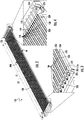
- FIGS. 2-4 a cutaway view of the evaporator assembly 100 is illustrated, according to an embodiment of the present disclosure.
- the working fluid 200 is conveyed from the inlet header 110 to the evaporator body 130 through a feed tube 300.
- the feed tube 300 is composed of an adapter 310 and a perforated tube 330.
- the adapter 310 fluidly connects the feed tube 300 to the inlet header 110.
- the perforated tube 330 may be tubular in shape as illustrated in FIGS. 2-4 .
- the perforated tube 330 includes a first end 332 and a second end 334 opposite the first end 332.
- the perforated tube 330 extends within and through a channel 140 formed within the evaporator body 130.
- the perforated tube 330 is fluidly connected to the adapter 310 at the first end 332 such that the working fluid 200 may flow from the inlet header 110 into the first end 332 of the perforated tube 330 through the adapter 310.
- the first end 332 is attached to the adapter 310.
- the second end 334 of the perforated tube 330 is located in the outlet header 120, as illustrated in FIG. 4 .
- the second end 334 is sealed off or closed, such that no working fluid 200 exits the perforated tube 330 at the second end 334.
- the perforated tube 330 extends within the evaporator body 130 through a channel 140 defined in the evaporator body 130.
- the evaporator body 130 is formed to define channels 140 that may be arranged in a linear formation 141 across a width W of the evaporator body 130.
- Each of the channels 140 can have a substantially same shape as the others.
- the perforated tube 330 includes a plurality of orifices 336 along a selected length L1 of the perforated tube 330.
- the selected length L1 may be less than an overall length of the perforated tube 330. As illustrated in FIGS. 2-4 , the selected length L1 does not extend from the first end 332 to the second end 334 but rather the selected length L1 is about equal to or less than a length L2 of the evaporator body 130.
- the plurality of orifices 336 start proximate the adapter 310 or right after the adapter 310 but terminate before the outlet header 130. There are no orifices 336 located in a portion of the perforated tube 330 that is located in the outlet header 120, as illustrated in FIG. 4 .
- the orifices 336 stop or cease to exist once the perforated tube 330 enters the outlet header 120.
- the orifices 336 fluidly connect the perforated tube 330 to the channel 140.
- the orifices 336 are configured to provide the working fluid 200 to the channels 140 of the evaporator body 130.
- the orifices 336 are configured to provide the working fluid 200 to the channels 140 in liquid form, where the heat 103 may transform at least a portion of the working fluid 200 to vapor form.
- the working fluid 200 then migrates from the channels 140 into the outlet header 120 at a channel outlet 146.
- the channel outlet 146 fluidly connects the channel 140 to the outlet header 120.
- the adapter 310 prevents or blocks the working fluid 200 from migrating from the channel 140 into the inlet header 110. In other words, the adapter 310 fluidly separates the channel 140 and the inlet header 110.
- the evaporative surfaces within the channel 140 of the evaporator body 130 may be continuously supplied with the working fluid 200 in a liquid phase.
- the pump 400 (see FIG. 1 ) is configured to deliver the working fluid 200 into the inlet 111, then to the inlet header 110, then into the adapter 310, and then into the perforated tube 330 at a selected pressure in a liquid form.
- the selected pressure is high enough to maintain working fluid 200 throughout an entirety of the perforated tube 330 at all times. In other words, the perforated tube 330 is always filled with working fluid 200 (i.e., completely filled).
- the perforated tube 330 is always filled with working fluid 200, the gravitation and the acceleration loads of any magnitude from any direction will not have any significant effect to the fill condition of the perforated tube 330 as long as the pump 400 is capable of generating enough pressure head to overcome the total system pressure drop.
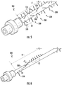
- FIGS. 5 and 6 different patterns of orifices 336 are illustrated, in accordance with an embodiment of the present disclosure. It is understood that while two patterns of orifices 336 are illustrated in FIGS. 5 and 6 , the embodiments disclosed herein may be applicable to any pattern of orifices 336. Some examples for other patterns may include but are not limited to a single row, multiple one-sided rows, partial areal coverage, or any other pattern conceivable by one of skill in the art.
- FIG. 5 illustrates a plurality of orifices 336 arranged circumferentially C1 around the perforated tube 330 at a plurality of locations 338 longitudinally L3 along the selected length L1 of the perforated tube 330.
- there may be any number of orifices 336 at each location 338.
- there may be six orifices 336 at each location 338, but it is understood that the embodiments disclosed herein may be applicable to more or less than six orifices at each location 338.
- the number of orifices 336 at each location may be equivalent to a number of grooves 142 (See FIGS.
- the orifices 336 may be aligned with each groove 142 such that working fluid 200 from the orifices 336 may be directed into the groove 142.
- the number of orifices 336 may vary but there may be enough orifices 336 such that the working fluid 200 can cover the evaporative surfaces of the channel 140.
- the orifices 336 are sized such that the flow of working fluid 200 is high enough to reach the evaporative surfaces of the channel 140.
- the evaporative surfaces includes the grooves 142.
- the orifices 336 may be intermittently spaced or regularly spaced circumferentially C1 around the perforated tube 330 at each location 338.
- the locations 338 may be intermittently spaced or regularly spaced (e.g., D1 is the same between each location) longitudinally L3 along the selected length L1 of the perforated tube 330.
- FIG. 6 illustrates a plurality of orifices 336 arranged in helically H1 around the perforated tube 330. There may be one orifices 336 at each location 338 as the plurality of orifices 336 winds helically H1 around the perforated tub 330. In other words, the plurality of orifices 336 are arranged in a line that winds circumferentially C1 around the perforated tube 330 while traversing longitudinally L3 along the selected length L1 of the perforated tube 330.
- the orifices 336 within the perforated tube 330 can be designed to have any pattern as long as the liquid stream of working fluid 200 emanating from the orifices 336 can cover the channel 140, which is a heat input surface of the evaporator body 130.
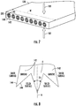
- grooves 142 formed within the channels 140 of the evaporator body 130 are illustrated, according to an embodiment of the present disclosure.
- the evaporator body 130 is formed to define channels 140 that may be arranged in a linear formation across a width W of the evaporator body 130.
- Each of the channels 140 can have a substantially same shape as the others and includes grooves 142 that are circumferentially arrayed to extend radially outwardly from an open central region 143 where the perforated tube 330 is located.
- each of the grooves 142 has a same shape as the others and is immediately adjacent to neighboring grooves 142.
- each of the grooves 142 is delimited by first and second interior facing sidewalls 144 of the evaporator body 130.
- the first and second interior facing sidewalls 144 are tapered toward each other to form a base B and an apex A.
- the apex A is opposite the base B and has an apex angle 2 ⁇ where ⁇ is less than 90° minus a solid-liquid contact angle.
- the apex angle 2 ⁇ is defined such that, for a fluid flow moving through one of the channels 140 in a microgravity environment where a portion of the fluid flow is in a liquid phase and another portion of the fluid flow is in a vapor phase, the portion of the fluid flow in the liquid phase within a particular groove 142 of the channel 140 will move in the particular groove 142 from the base B to the apex A and the portion of the fluid flow in the vapor phase within the particular groove 142 will move in the particular groove 142 from the apex A to the base B.
- FIG. 9 an operation of the channels 140 and the grooves 142 in a microgravity environment is illustrated, in accordance with an embodiment of the present disclosure.
- the liquid moves in the direction from the base B and to the apex A.
- the vapor is expelled from the apex A toward the base B and to the open central region 143 where the perforated tube 330 is located.
- the gravity field G1 does not affect the distribution of the working fluid 200 to grooves 142 of the channels 140 because the working fluid 330 is pressurized and is directed out of the perforated tube 330 towards the grooves 142. Therefore, more heat transfer may occur between the evaporator body 130 and the working fluid 330 because the working fluid 200 is not susceptible to the gravity field G1.
Landscapes
- Engineering & Computer Science (AREA)
- Physics & Mathematics (AREA)
- Thermal Sciences (AREA)
- Mechanical Engineering (AREA)
- General Engineering & Computer Science (AREA)
- Geometry (AREA)
- Chemical & Material Sciences (AREA)
- Crystallography & Structural Chemistry (AREA)
- Heat-Exchange Devices With Radiators And Conduit Assemblies (AREA)
Abstract
Description
- The subject matter disclosed herein relates generally to the field of evaporators, and specifically to an evaporator for terrestrial and microgravity environments.
- Evaporators utilize latent heat of a fluid to absorb waste heat from a heat source. As such, in order to operate efficiently, an evaporating surface of an evaporator should be covered by a layer of a liquid phase of a working fluid as much as possible during operational conditions.
- The liquid phase of a working fluid (i.e., liquid) tends to accumulate and move in the direction of gravity in a terrestrial environment. In a microgravity environment, liquid distribution is randomized and tends to move freely if undisturbed. Therefore, in each of these terrestrial and microgravity environment cases, it is often critical to replenish evaporating surfaces of evaporators with liquid.
- According to one embodiment, an evaporator assembly is provided. The evaporator assembly includes an inlet header, an outlet header, and an evaporator body extending from the inlet header to the outlet header. The evaporator body defining a channel fluidly connected to the outlet header. The evaporator assembly further includes a feed tube including: an adapter fluidly connected to the inlet header and a perforated tube fluidly connected to the inlet header through the adapter. The perforated tube including a first end attached to the adapter, a second end opposite the first end, and a plurality of orifices fluidly connecting the perforated tube to the channel. The perforated tube extends within the channel.
- In addition to one or more of the features described above, or as an alternative, further embodiments may include that the second end of the perforated tube is located in the outlet header.
- In addition to one or more of the features described above, or as an alternative, further embodiments may include that the second end of the perforated tube is sealed off.
- In addition to one or more of the features described above, or as an alternative, further embodiments may include that the plurality of orifices extend circumferentially around the perforated tube.
- In addition to one or more of the features described above, or as an alternative, further embodiments may include that the plurality of orifices extend longitudinally along a selected length of the perforated tube.
- In addition to one or more of the features described above, or as an alternative, further embodiments may include that the selected length is less than or equal to a length of the evaporator body.
- In addition to one or more of the features described above, or as an alternative, further embodiments may include that the plurality of orifices start proximate the adapter and terminate before the outlet header.
- In addition to one or more of the features described above, or as an alternative, further embodiments may include that the plurality of orifices extend helically around the perforated tube.
- In addition to one or more of the features described above, or as an alternative, further embodiments may include that the plurality of orifices are arranged circumferentially around the perforated tube at a plurality of locations longitudinally along a selected length of the perforated tube.
- In addition to one or more of the features described above, or as an alternative, further embodiments may include that the channel includes grooves respectively delimited by first and second interior facing sidewalls of the evaporator body which form a base and an apex with an apex angle opposite the base and defined such that, for a fluid flow moving through the channel in a microgravity environment: a portion of the fluid flow in a liquid phase within a groove of the channel will move in the groove from the base to the apex, and a portion of the fluid flow in a vapor phase within a groove of the channel will move in the groove from the apex to the base.
- In addition to one or more of the features described above, or as an alternative, further embodiments may include that the groove circumferentially arrayed to extend outwardly from an open central region where the perforated tube is located.
- In addition to one or more of the features described above, or as an alternative, further embodiments may include that the apex angle is 2β and β is less than 90° minus a solid-liquid contact angle.
- In addition to one or more of the features described above, or as an alternative, further embodiments may include a fluid pump fluidly connected to the inlet header. The fluid pump being configured to deliver a working fluid at a selected pressure to maintain the working fluid through an entirety of the perforated tube.
- In addition to one or more of the features described above, or as an alternative, further embodiments may include that the adapter is configured to block working fluid from migrating from the channel into the inlet header.
- According to another embodiment, a feed tube for an evaporator assembly is provided. The feed tube including an adapter and a perforated tube connected to the adapter. The perforated tube including a first end attached to the adapter, a second end opposite the first end, and a plurality of orifices.
- In addition to one or more of the features described above, or as an alternative, further embodiments may include that the second end of the perforated tube is sealed off.
- In addition to one or more of the features described above, or as an alternative, further embodiments may include that the plurality of orifices extend circumferentially around the perforated tube.
- In addition to one or more of the features described above, or as an alternative, further embodiments may include that the plurality of orifices extend longitudinally along a selected length of the perforated tube.
- In addition to one or more of the features described above, or as an alternative, further embodiments may include that the plurality of orifices extend helically around the perforated tube.
- In addition to one or more of the features described above, or as an alternative, further embodiments may include that the plurality of orifices are arranged circumferentially around the perforated tube at a plurality of locations longitudinally along a selected length of the perforated tube.
- The foregoing features and elements may be combined in various combinations without exclusivity, unless expressly indicated otherwise. These features and elements as well as the operation thereof will become more apparent in light of the following description and the accompanying drawings. It should be understood, however, that the following description and drawings are intended to be illustrative and explanatory in nature and non-limiting.
- The following descriptions should not be considered limiting in any way. With reference to the accompanying drawings, like elements are numbered alike:
-
FIG. 1 is a perspective view of an evaporator assembly, in accordance with an embodiment of the present disclosure; -
FIG. 2 is a cutaway view of the evaporator assembly, in accordance with an embodiment of the present disclosure; -
FIG. 3 is an enlarged cutaway view of an inlet header of the evaporator assembly ofFIG. 2 , in accordance with an embodiment of the present disclosure; -
FIG. 4 is an enlarged cutaway view of an outlet header of the evaporator assembly ofFIG. 2 , in accordance with an embodiment of the present disclosure; -
FIG. 5 is an isometric view of a feed tube of the evaporator assembly, in accordance with an embodiment of the present disclosure; -
FIG. 6 is an isometric view of a feed tube of the evaporator assembly, in accordance with an embodiment of the present disclosure; -
FIG. 7 is a perspective view of a body and channels of the evaporator assembly ofFIG. 1 , in accordance with an embodiment of the present disclosure; -
FIG. 8 is an axial view illustrating a configuration of grooves of the channels ofFIG. 7 , in accordance with an embodiment of the present disclosure; -
FIG. 9 is an illustration of an operation of the groove channels ofFIG 7 in a microgravity environment, in accordance with an embodiment of the present disclosure; and -
FIG. 10 is an illustration of an operation of the groove channels ofFIG 7 in a gravity field, in accordance with an embodiment of the present disclosure. - A detailed description of one or more embodiments of the disclosed apparatus and method are presented herein by way of exemplification and not limitation with reference to the Figures.
- Movement of a working fluid of an evaporator in a microgravity environment is mainly dictated by a surface tension of the working fluid, characteristics of a surface the working fluid is intended to be in contact with and external disturbances applied to the system. In a terrestrial environment, the working fluid will tend to pool and flow in the direction of gravity. In either case, in a properly designed groove, working fluid can be replenished into the groove and vapor can be expelled out of the groove at similar rates which is useful in the replenishment of working fluid on an evaporating surface of an evaporator. As such, as will be described below, a groove geometry in which working fluid can be replenished into the groove and vapor can be expelled out of the groove at similar rates in integrated into an evaporator design. The evaporator design, according to one or more embodiments, is therefore suitable for both terrestrial and microgravity environments.
- Additionally for a long evaporator oriented against gravity or under an adverse acceleration load, the working fluid may not be able to wet the entire length of the evaporator, and thus the evaporator will not have the designed efficiency of the temperature uniformity. The embodiments disclose herein seek to correct this inefficiency by allowing the working fluid to wed the entire length of the evaporator using a perforated tube installed along the length of the evaporator.
- Referring now to
FIG. 1 , an isometric view of anevaporator assembly 100 is illustrated, according to an embodiment of the present disclosure. Theevaporator assembly 100 includes aninlet header 110, anevaporator body 130, and anoutlet header 120. Theevaporator body 130 is interposed between theinlet header 110 and theoutlet header 120 and extends from theinlet header 110 to theoutlet header 120. Theevaporator body 130 is the evaporating element of theevaporator assembly 100. Afluid pump 400 is fluidly connected to the inlet header at theinlet 111. Thepump 400 is configured to deliver a workingfluid 200 to theevaporator assembly 100 at a selected pressure. The workingfluid 200 enters theinlet header 110 at aninlet 111. The workingfluid 200 then flows from theinlet header 110 to theoutlet header 120 through the evaporator body 101 in aflow direction 104. The workingfluid 200 absorbsheat 103 from a heat source while flowing through theevaporator body 130. The fluid then exits theoutlet header 120 through anoutlet 121 at theoutlet header 120. - Referring now to
FIGS. 2-4 , with continued reference toFIG. 1 , a cutaway view of theevaporator assembly 100 is illustrated, according to an embodiment of the present disclosure. The workingfluid 200 is conveyed from theinlet header 110 to theevaporator body 130 through afeed tube 300. It is understood that, although discussed herein in the singular tense, theevaporator assembly 100 may includemultiple feed tubes 300, as illustrated inFIGS. 2-4 . Thefeed tube 300 is composed of anadapter 310 and aperforated tube 330. Theadapter 310 fluidly connects thefeed tube 300 to theinlet header 110. - The
perforated tube 330 may be tubular in shape as illustrated inFIGS. 2-4 . Theperforated tube 330 includes afirst end 332 and asecond end 334 opposite thefirst end 332. Theperforated tube 330 extends within and through achannel 140 formed within theevaporator body 130. Theperforated tube 330 is fluidly connected to theadapter 310 at thefirst end 332 such that the workingfluid 200 may flow from theinlet header 110 into thefirst end 332 of theperforated tube 330 through theadapter 310. Thefirst end 332 is attached to theadapter 310. In an embodiment, thesecond end 334 of theperforated tube 330 is located in theoutlet header 120, as illustrated inFIG. 4 . In an embodiment, thesecond end 334 is sealed off or closed, such that no workingfluid 200 exits theperforated tube 330 at thesecond end 334. - The
perforated tube 330 extends within theevaporator body 130 through achannel 140 defined in theevaporator body 130. Theevaporator body 130 is formed to definechannels 140 that may be arranged in a linear formation 141 across a width W of theevaporator body 130. Each of thechannels 140 can have a substantially same shape as the others. - The
perforated tube 330 includes a plurality oforifices 336 along a selected length L1 of theperforated tube 330. The selected length L1 may be less than an overall length of theperforated tube 330. As illustrated inFIGS. 2-4 , the selected length L1 does not extend from thefirst end 332 to thesecond end 334 but rather the selected length L1 is about equal to or less than a length L2 of theevaporator body 130. The plurality oforifices 336 start proximate theadapter 310 or right after theadapter 310 but terminate before theoutlet header 130. There are noorifices 336 located in a portion of theperforated tube 330 that is located in theoutlet header 120, as illustrated inFIG. 4 . In other words, theorifices 336 stop or cease to exist once theperforated tube 330 enters theoutlet header 120. Theorifices 336 fluidly connect theperforated tube 330 to thechannel 140. Theorifices 336 are configured to provide the workingfluid 200 to thechannels 140 of theevaporator body 130. Theorifices 336 are configured to provide the workingfluid 200 to thechannels 140 in liquid form, where theheat 103 may transform at least a portion of the workingfluid 200 to vapor form. The workingfluid 200 then migrates from thechannels 140 into theoutlet header 120 at achannel outlet 146. Thechannel outlet 146 fluidly connects thechannel 140 to theoutlet header 120. Theadapter 310 prevents or blocks the workingfluid 200 from migrating from thechannel 140 into theinlet header 110. In other words, theadapter 310 fluidly separates thechannel 140 and theinlet header 110. - In order to ensure that the
evaporator assembly 100 can operate as efficiently as possible under any gravitational or acceleration load from any direction, the evaporative surfaces within thechannel 140 of theevaporator body 130 may be continuously supplied with the workingfluid 200 in a liquid phase. - The pump 400 (see
FIG. 1 ) is configured to deliver the workingfluid 200 into theinlet 111, then to theinlet header 110, then into theadapter 310, and then into theperforated tube 330 at a selected pressure in a liquid form. The selected pressure is high enough to maintain workingfluid 200 throughout an entirety of theperforated tube 330 at all times. In other words, theperforated tube 330 is always filled with working fluid 200 (i.e., completely filled). - Advantageously, since the
perforated tube 330 is always filled with workingfluid 200, the gravitation and the acceleration loads of any magnitude from any direction will not have any significant effect to the fill condition of theperforated tube 330 as long as thepump 400 is capable of generating enough pressure head to overcome the total system pressure drop. - Referring now to
FIGS. 5 and 6 , different patterns oforifices 336 are illustrated, in accordance with an embodiment of the present disclosure. It is understood that while two patterns oforifices 336 are illustrated inFIGS. 5 and 6 , the embodiments disclosed herein may be applicable to any pattern oforifices 336. Some examples for other patterns may include but are not limited to a single row, multiple one-sided rows, partial areal coverage, or any other pattern conceivable by one of skill in the art. -
FIG. 5 illustrates a plurality oforifices 336 arranged circumferentially C1 around theperforated tube 330 at a plurality oflocations 338 longitudinally L3 along the selected length L1 of theperforated tube 330. In other words, at eachlocation 338 there the orifices 366 arranged circumferentially C1 around the peroratedtube 330. There may be any number oforifices 336 at eachlocation 338. In an embodiment, there may be sixorifices 336 at eachlocation 338, but it is understood that the embodiments disclosed herein may be applicable to more or less than six orifices at eachlocation 338. The number oforifices 336 at each location may be equivalent to a number of grooves 142 (SeeFIGS. 7-10 ) in eachchannel 140. Theorifices 336 may be aligned with eachgroove 142 such that workingfluid 200 from theorifices 336 may be directed into thegroove 142. The number oforifices 336 may vary but there may beenough orifices 336 such that the workingfluid 200 can cover the evaporative surfaces of thechannel 140. Theorifices 336 are sized such that the flow of workingfluid 200 is high enough to reach the evaporative surfaces of thechannel 140. The evaporative surfaces includes thegrooves 142. Theorifices 336 may be intermittently spaced or regularly spaced circumferentially C1 around theperforated tube 330 at eachlocation 338. Thelocations 338 may be intermittently spaced or regularly spaced (e.g., D1 is the same between each location) longitudinally L3 along the selected length L1 of theperforated tube 330. -
FIG. 6 illustrates a plurality oforifices 336 arranged in helically H1 around theperforated tube 330. There may be oneorifices 336 at eachlocation 338 as the plurality oforifices 336 winds helically H1 around theperforated tub 330. In other words, the plurality oforifices 336 are arranged in a line that winds circumferentially C1 around theperforated tube 330 while traversing longitudinally L3 along the selected length L1 of theperforated tube 330. - Advantageously, the
orifices 336 within theperforated tube 330 can be designed to have any pattern as long as the liquid stream of workingfluid 200 emanating from theorifices 336 can cover thechannel 140, which is a heat input surface of theevaporator body 130. - Referring now to
FIGS. 7 and 8 , with continued reference toFIGS. 1-6 ,grooves 142 formed within thechannels 140 of theevaporator body 130 are illustrated, according to an embodiment of the present disclosure. Theevaporator body 130 is formed to definechannels 140 that may be arranged in a linear formation across a width W of theevaporator body 130. Each of thechannels 140 can have a substantially same shape as the others and includesgrooves 142 that are circumferentially arrayed to extend radially outwardly from an opencentral region 143 where theperforated tube 330 is located. - Each of the
grooves 142 has a same shape as the others and is immediately adjacent to neighboringgrooves 142. In addition, each of thegrooves 142 is delimited by first and second interior facing sidewalls 144 of theevaporator body 130. The first and secondinterior facing sidewalls 144 are tapered toward each other to form a base B and an apex A. The apex A is opposite the base B and has an apex angle 2β where β is less than 90° minus a solid-liquid contact angle. That is, the apex angle 2β is defined such that, for a fluid flow moving through one of thechannels 140 in a microgravity environment where a portion of the fluid flow is in a liquid phase and another portion of the fluid flow is in a vapor phase, the portion of the fluid flow in the liquid phase within aparticular groove 142 of thechannel 140 will move in theparticular groove 142 from the base B to the apex A and the portion of the fluid flow in the vapor phase within theparticular groove 142 will move in theparticular groove 142 from the apex A to the base B. - Referring now to
FIG. 9 , with continued reference toFIGS. 1-8 , an operation of thechannels 140 and thegrooves 142 in a microgravity environment is illustrated, in accordance with an embodiment of the present disclosure. As shown inFIG. 9 , in the microgravity environment, once liquid contacts the first and second interior facing sidewalls 144 of each of thegrooves 142, the liquid moves in the direction from the base B and to the apex A. After vaporization by exposure of theevaporator body 130 to heat 103, the vapor is expelled from the apex A toward the base B and to the opencentral region 143 where theperforated tube 330 is located. - Referring now to
FIG. 10 , with continued reference toFIGS. 1-9 , an operation of thechannels 140 and thegrooves 142 in a gravity field G1 is illustrated, in accordance with an embodiment of the present disclosure. As shown inFIG. 10 , the gravity field G1 does not affect the distribution of the workingfluid 200 togrooves 142 of thechannels 140 because the workingfluid 330 is pressurized and is directed out of theperforated tube 330 towards thegrooves 142. Therefore, more heat transfer may occur between theevaporator body 130 and the workingfluid 330 because the workingfluid 200 is not susceptible to the gravity field G1. - Technical effects and benefits of the features described herein include utilizing pressurized perforated tubes to more equally distribute a working fluid in liquid form across a heat transfer surface of an evaporator in both microgravity environments and terrestrial environments.
- A detailed description of one or more embodiments of the disclosed apparatus and method are presented herein by way of exemplification and not limitation with reference to the Figures.
- The term "about" is intended to include the degree of error associated with measurement of the particular quantity based upon the equipment available at the time of filing the application.
- The terminology used herein is for the purpose of describing particular embodiments only and is not intended to be limiting of the present disclosure. As used herein, the singular forms "a", "an" and "the" are intended to include the plural forms as well, unless the context clearly indicates otherwise. It will be further understood that the terms "comprises" and/or "comprising," when used in this specification, specify the presence of stated features, integers, steps, operations, elements, and/or components, but do not preclude the presence or addition of one or more other features, integers, steps, operations, element components, and/or groups thereof.
- While the present disclosure has been described with reference to an exemplary embodiment or embodiments, it will be understood by those skilled in the art that various changes may be made and equivalents may be substituted for elements thereof without departing from the scope of the present disclosure as defined by the claims. In addition, many modifications may be made to adapt a particular situation or material to the teachings of the present disclosure without departing from the scope thereof. Therefore, it is intended that the present disclosure not be limited to the particular embodiment disclosed as the best mode contemplated for carrying out this present disclosure, but that the present disclosure will include all embodiments falling within the scope of the claims.
Claims (15)
- A feed tube (300) for an evaporator assembly (100), the feed tube comprising:an adapter (310); anda perforated tube (330) connected to the adapter, the perforated tube comprising a first end (332) attached to the adapter, a second end (334) opposite the first end, and a plurality of orifices (336).
- The feed tube of claim 1, wherein the second end of the perforated tube is sealed off.
- The feed tube of claim 1 or 2, wherein the plurality of orifices extend circumferentially around the perforated tube
- The feed tube of claim 1 or 2, wherein the plurality of orifices extend longitudinally along a selected length of the perforated tube
- The feed tube of claim 1 or 2, wherein the plurality of orifices extend helically around the perforated tube
- The feed tube of claim 1 or 2, wherein the plurality of orifices are arranged circumferentially around the perforated tube at a plurality of locations longitudinally along a selected length of the perforated tube.
- An evaporator assembly (100), comprising:an inlet header (110);an outlet header (120);an evaporator body (130) extending from the inlet header to the outlet header, the evaporator body defining a channel (140) fluidly connected to the outlet header;the feed tube (300) according to any preceding claim;wherein the adapter (310) is fluidly connected to the inlet header; andthe perforated tube (330) is fluidly connected to the inlet header through the adapter, wherein the plurality of orifices (336) fluidly connect the perforated tube to the channel, wherein the perforated tube extends within the channel.
- The evaporator assembly of claim 7, wherein the second end of the perforated tube is located in the outlet header
- The evaporator assembly of claim 7 or 8, when dependent upon claim 4; wherein the selected length is less than or equal to a length of the evaporator body.
- The evaporator assembly of claim 7, 8, or 9, wherein the plurality of orifices (336) start proximate the adapter (310) and terminate before the outlet header (120).
- The evaporator assembly of any of claims 7 to 10, wherein the channel comprises grooves (142) respectively delimited by first and second interior facing sidewalls of the evaporator body which form a base and an apex (A) with an apex angle opposite the base (B) and defined such that, for a fluid flow moving through the channel in a microgravity environment:a portion of the fluid flow in a liquid phase within a groove of the channel will move in the groove from the base to the apex, anda portion of the fluid flow in a vapor phase within a groove of the channel will move in the groove from the apex to the base.
- The evaporator assembly of claim 11, wherein the groove circumferentially arrayed to extend outwardly from an open central region where the perforated tube is located.
- The evaporator assembly of claim 11 or 12, wherein the apex angle is 2β and β is less than 90° minus a solid-liquid contact angle.
- The evaporator assembly of any of claims 7 to 13, further comprising:
a fluid pump (400) fluidly connected to the inlet header, the fluid pump being configured to deliver a working fluid (200) at a selected pressure to maintain the working fluid through an entirety of the perforated tube. - The evaporator assembly of any of claims 7 to 14, wherein the adapter (310) is configured to block working fluid from migrating from the channel into the inlet header.
Applications Claiming Priority (1)
| Application Number | Priority Date | Filing Date | Title |
|---|---|---|---|
| US16/890,121 US11656010B2 (en) | 2020-06-02 | 2020-06-02 | Evaporator with feed tube flow distributors for random gravitation and acceleration fields |
Publications (2)
| Publication Number | Publication Date |
|---|---|
| EP3919848A1 true EP3919848A1 (en) | 2021-12-08 |
| EP3919848B1 EP3919848B1 (en) | 2024-10-23 |
Family
ID=75977702
Family Applications (1)
| Application Number | Title | Priority Date | Filing Date |
|---|---|---|---|
| EP21174473.5A Active EP3919848B1 (en) | 2020-06-02 | 2021-05-18 | Evaporator with feed tube flow distributors for random gravitation and acceleration fields |
Country Status (2)
| Country | Link |
|---|---|
| US (1) | US11656010B2 (en) |
| EP (1) | EP3919848B1 (en) |
Citations (10)
| Publication number | Priority date | Publication date | Assignee | Title |
|---|---|---|---|---|
| US2611584A (en) * | 1947-03-22 | 1952-09-23 | Trane Co | Heat exchanger |
| US3026092A (en) * | 1958-08-18 | 1962-03-20 | Marlo Coil Company | Heat exchanger |
| WO1994014021A1 (en) * | 1992-12-07 | 1994-06-23 | Multistack International Limited | Improvements in plate heat-exchangers |
| US5651268A (en) * | 1995-01-05 | 1997-07-29 | Nippondeso Co., Ltd. | Refrigerant evaporator |
| EP0798533A1 (en) * | 1996-03-29 | 1997-10-01 | Sanden Corporation | Heat exchanger with a distribution device capable of uniformly distributing a medium to a plurality of exchanger tubes |
| JP2004278935A (en) * | 2003-03-17 | 2004-10-07 | Calsonic Kansei Corp | Evaporator |
| US20090000327A1 (en) * | 2005-12-14 | 2009-01-01 | Behr Gmbh& Co.Kg | Heat Pump |
| CN101782297A (en) * | 2009-01-19 | 2010-07-21 | 三花丹佛斯(杭州)微通道换热器有限公司 | Heat exchanger |
| US20110290465A1 (en) * | 2010-06-01 | 2011-12-01 | Delphi Technologies, Inc. | Orientation insensitive refrigerant distributor tube |
| EP3067652A1 (en) * | 2015-03-11 | 2016-09-14 | Politechnika Gdanska | Heat exchanger and method for exchanging heat |
Family Cites Families (6)
| Publication number | Priority date | Publication date | Assignee | Title |
|---|---|---|---|---|
| US2816738A (en) * | 1956-02-17 | 1957-12-17 | John J Nesbitt Inc | Heat exchanger |
| US4007601A (en) | 1975-10-16 | 1977-02-15 | The United States Of America As Represented By The Administrator Of The National Aeronautics And Space Administration | Tubular sublimator/evaporator heat sink |
| DE3526574C1 (en) * | 1985-07-25 | 1987-03-26 | Dornier System Gmbh | Capillary supported evaporator |
| DE3750962T2 (en) | 1986-04-04 | 1995-05-11 | Seiko Epson Corp | Device for generating an image on a recording material. |
| JP4738401B2 (en) * | 2007-11-28 | 2011-08-03 | 三菱電機株式会社 | Air conditioner |
| CN102278904B (en) | 2011-07-29 | 2013-03-06 | 华北电力大学 | Internal liquid-dividing hood-type condensed heat-exchanging pipe |
-
2020
- 2020-06-02 US US16/890,121 patent/US11656010B2/en active Active
-
2021
- 2021-05-18 EP EP21174473.5A patent/EP3919848B1/en active Active
Patent Citations (10)
| Publication number | Priority date | Publication date | Assignee | Title |
|---|---|---|---|---|
| US2611584A (en) * | 1947-03-22 | 1952-09-23 | Trane Co | Heat exchanger |
| US3026092A (en) * | 1958-08-18 | 1962-03-20 | Marlo Coil Company | Heat exchanger |
| WO1994014021A1 (en) * | 1992-12-07 | 1994-06-23 | Multistack International Limited | Improvements in plate heat-exchangers |
| US5651268A (en) * | 1995-01-05 | 1997-07-29 | Nippondeso Co., Ltd. | Refrigerant evaporator |
| EP0798533A1 (en) * | 1996-03-29 | 1997-10-01 | Sanden Corporation | Heat exchanger with a distribution device capable of uniformly distributing a medium to a plurality of exchanger tubes |
| JP2004278935A (en) * | 2003-03-17 | 2004-10-07 | Calsonic Kansei Corp | Evaporator |
| US20090000327A1 (en) * | 2005-12-14 | 2009-01-01 | Behr Gmbh& Co.Kg | Heat Pump |
| CN101782297A (en) * | 2009-01-19 | 2010-07-21 | 三花丹佛斯(杭州)微通道换热器有限公司 | Heat exchanger |
| US20110290465A1 (en) * | 2010-06-01 | 2011-12-01 | Delphi Technologies, Inc. | Orientation insensitive refrigerant distributor tube |
| EP3067652A1 (en) * | 2015-03-11 | 2016-09-14 | Politechnika Gdanska | Heat exchanger and method for exchanging heat |
Also Published As
| Publication number | Publication date |
|---|---|
| US20210372673A1 (en) | 2021-12-02 |
| EP3919848B1 (en) | 2024-10-23 |
| US11656010B2 (en) | 2023-05-23 |
Similar Documents
| Publication | Publication Date | Title |
|---|---|---|
| US6450132B1 (en) | Loop type heat pipe | |
| JP6408572B2 (en) | Heat exchanger | |
| JP6002316B2 (en) | Heat exchanger | |
| JP2016525205A5 (en) | ||
| JP2016525205A (en) | Heat exchanger | |
| US10458665B2 (en) | Passive liquid collecting device | |
| EP3919848B1 (en) | Evaporator with feed tube flow distributors for random gravitation and acceleration fields | |
| US11788803B2 (en) | Insert for evaporator header | |
| EP3637024B1 (en) | Thermal control loop | |
| US20240027141A1 (en) | Evaporator with grooved channels | |
| US20200080789A1 (en) | Shell and tube heat exchanger with perforated fins interconnecting the tubes | |
| PT83596B (en) | METHOD AND AUTOMATIC DEVICE FOR CLEANING A HEAT EXCHANGER FOR GAS FLUIDS | |
| EP3859258B1 (en) | Evaporator with grooved channels | |
| RU2750511C2 (en) | Heat exchanger with a fluid/gas mixing device having holes with an improved shape | |
| US4690210A (en) | Fluid jet impingement heat exchanger for operation in zero gravity conditions | |
| EP3943305A1 (en) | Spiral heat exchanger with monolithic phase change material chamber | |
| US10458714B2 (en) | Heat exchanger assembly | |
| EP0106544B1 (en) | Distributor apparatus for fluid including a gaseous and liquid phase | |
| JP2764174B2 (en) | Falling liquid film evaporator | |
| US5314011A (en) | Heat pipe | |
| CN106461342B (en) | Compact heat exchanger | |
| JP2005300073A (en) | Evaporator | |
| KR0181662B1 (en) | Liquid refrigerant flow distributor in refrigeration unit | |
| HK1205245A1 (en) | Heat exchanger |
Legal Events
| Date | Code | Title | Description |
|---|---|---|---|
| PUAI | Public reference made under article 153(3) epc to a published international application that has entered the european phase |
Free format text: ORIGINAL CODE: 0009012 |
|
| STAA | Information on the status of an ep patent application or granted ep patent |
Free format text: STATUS: THE APPLICATION HAS BEEN PUBLISHED |
|
| AK | Designated contracting states |
Kind code of ref document: A1 Designated state(s): AL AT BE BG CH CY CZ DE DK EE ES FI FR GB GR HR HU IE IS IT LI LT LU LV MC MK MT NL NO PL PT RO RS SE SI SK SM TR |
|
| B565 | Issuance of search results under rule 164(2) epc |
Effective date: 20211020 |
|
| STAA | Information on the status of an ep patent application or granted ep patent |
Free format text: STATUS: REQUEST FOR EXAMINATION WAS MADE |
|
| 17P | Request for examination filed |
Effective date: 20220608 |
|
| RBV | Designated contracting states (corrected) |
Designated state(s): AL AT BE BG CH CY CZ DE DK EE ES FI FR GB GR HR HU IE IS IT LI LT LU LV MC MK MT NL NO PL PT RO RS SE SI SK SM TR |
|
| STAA | Information on the status of an ep patent application or granted ep patent |
Free format text: STATUS: EXAMINATION IS IN PROGRESS |
|
| 17Q | First examination report despatched |
Effective date: 20230503 |
|
| GRAP | Despatch of communication of intention to grant a patent |
Free format text: ORIGINAL CODE: EPIDOSNIGR1 |
|
| STAA | Information on the status of an ep patent application or granted ep patent |
Free format text: STATUS: GRANT OF PATENT IS INTENDED |
|
| INTG | Intention to grant announced |
Effective date: 20240521 |
|
| GRAS | Grant fee paid |
Free format text: ORIGINAL CODE: EPIDOSNIGR3 |
|
| GRAA | (expected) grant |
Free format text: ORIGINAL CODE: 0009210 |
|
| STAA | Information on the status of an ep patent application or granted ep patent |
Free format text: STATUS: THE PATENT HAS BEEN GRANTED |
|
| AK | Designated contracting states |
Kind code of ref document: B1 Designated state(s): AL AT BE BG CH CY CZ DE DK EE ES FI FR GB GR HR HU IE IS IT LI LT LU LV MC MK MT NL NO PL PT RO RS SE SI SK SM TR |
|
| REG | Reference to a national code |
Ref country code: GB Ref legal event code: FG4D |
|
| REG | Reference to a national code |
Ref country code: CH Ref legal event code: EP |
|
| REG | Reference to a national code |
Ref country code: DE Ref legal event code: R096 Ref document number: 602021020541 Country of ref document: DE |
|
| REG | Reference to a national code |
Ref country code: IE Ref legal event code: FG4D |
|
| REG | Reference to a national code |
Ref country code: LT Ref legal event code: MG9D |
|
| REG | Reference to a national code |
Ref country code: NL Ref legal event code: MP Effective date: 20241023 |
|
| REG | Reference to a national code |
Ref country code: AT Ref legal event code: MK05 Ref document number: 1735167 Country of ref document: AT Kind code of ref document: T Effective date: 20241023 |
|
| PG25 | Lapsed in a contracting state [announced via postgrant information from national office to epo] |
Ref country code: NL Free format text: LAPSE BECAUSE OF FAILURE TO SUBMIT A TRANSLATION OF THE DESCRIPTION OR TO PAY THE FEE WITHIN THE PRESCRIBED TIME-LIMIT Effective date: 20241023 |
|
| PG25 | Lapsed in a contracting state [announced via postgrant information from national office to epo] |
Ref country code: NL Free format text: LAPSE BECAUSE OF FAILURE TO SUBMIT A TRANSLATION OF THE DESCRIPTION OR TO PAY THE FEE WITHIN THE PRESCRIBED TIME-LIMIT Effective date: 20241023 |
|
| PG25 | Lapsed in a contracting state [announced via postgrant information from national office to epo] |
Ref country code: IS Free format text: LAPSE BECAUSE OF FAILURE TO SUBMIT A TRANSLATION OF THE DESCRIPTION OR TO PAY THE FEE WITHIN THE PRESCRIBED TIME-LIMIT Effective date: 20250223 Ref country code: PT Free format text: LAPSE BECAUSE OF FAILURE TO SUBMIT A TRANSLATION OF THE DESCRIPTION OR TO PAY THE FEE WITHIN THE PRESCRIBED TIME-LIMIT Effective date: 20250224 Ref country code: HR Free format text: LAPSE BECAUSE OF FAILURE TO SUBMIT A TRANSLATION OF THE DESCRIPTION OR TO PAY THE FEE WITHIN THE PRESCRIBED TIME-LIMIT Effective date: 20241023 |
|
| PG25 | Lapsed in a contracting state [announced via postgrant information from national office to epo] |
Ref country code: FI Free format text: LAPSE BECAUSE OF FAILURE TO SUBMIT A TRANSLATION OF THE DESCRIPTION OR TO PAY THE FEE WITHIN THE PRESCRIBED TIME-LIMIT Effective date: 20241023 |
|
| PG25 | Lapsed in a contracting state [announced via postgrant information from national office to epo] |
Ref country code: BG Free format text: LAPSE BECAUSE OF FAILURE TO SUBMIT A TRANSLATION OF THE DESCRIPTION OR TO PAY THE FEE WITHIN THE PRESCRIBED TIME-LIMIT Effective date: 20241023 |
|
| PG25 | Lapsed in a contracting state [announced via postgrant information from national office to epo] |
Ref country code: ES Free format text: LAPSE BECAUSE OF FAILURE TO SUBMIT A TRANSLATION OF THE DESCRIPTION OR TO PAY THE FEE WITHIN THE PRESCRIBED TIME-LIMIT Effective date: 20241023 |
|
| PG25 | Lapsed in a contracting state [announced via postgrant information from national office to epo] |
Ref country code: NO Free format text: LAPSE BECAUSE OF FAILURE TO SUBMIT A TRANSLATION OF THE DESCRIPTION OR TO PAY THE FEE WITHIN THE PRESCRIBED TIME-LIMIT Effective date: 20250123 |
|
| PG25 | Lapsed in a contracting state [announced via postgrant information from national office to epo] |
Ref country code: LV Free format text: LAPSE BECAUSE OF FAILURE TO SUBMIT A TRANSLATION OF THE DESCRIPTION OR TO PAY THE FEE WITHIN THE PRESCRIBED TIME-LIMIT Effective date: 20241023 Ref country code: AT Free format text: LAPSE BECAUSE OF FAILURE TO SUBMIT A TRANSLATION OF THE DESCRIPTION OR TO PAY THE FEE WITHIN THE PRESCRIBED TIME-LIMIT Effective date: 20241023 Ref country code: GR Free format text: LAPSE BECAUSE OF FAILURE TO SUBMIT A TRANSLATION OF THE DESCRIPTION OR TO PAY THE FEE WITHIN THE PRESCRIBED TIME-LIMIT Effective date: 20250124 |
|
| PG25 | Lapsed in a contracting state [announced via postgrant information from national office to epo] |
Ref country code: PL Free format text: LAPSE BECAUSE OF FAILURE TO SUBMIT A TRANSLATION OF THE DESCRIPTION OR TO PAY THE FEE WITHIN THE PRESCRIBED TIME-LIMIT Effective date: 20241023 |
|
| PG25 | Lapsed in a contracting state [announced via postgrant information from national office to epo] |
Ref country code: RS Free format text: LAPSE BECAUSE OF FAILURE TO SUBMIT A TRANSLATION OF THE DESCRIPTION OR TO PAY THE FEE WITHIN THE PRESCRIBED TIME-LIMIT Effective date: 20250123 |
|
| PG25 | Lapsed in a contracting state [announced via postgrant information from national office to epo] |
Ref country code: SM Free format text: LAPSE BECAUSE OF FAILURE TO SUBMIT A TRANSLATION OF THE DESCRIPTION OR TO PAY THE FEE WITHIN THE PRESCRIBED TIME-LIMIT Effective date: 20241023 |
|
| PGFP | Annual fee paid to national office [announced via postgrant information from national office to epo] |
Ref country code: DE Payment date: 20250423 Year of fee payment: 5 |
|
| PG25 | Lapsed in a contracting state [announced via postgrant information from national office to epo] |
Ref country code: DK Free format text: LAPSE BECAUSE OF FAILURE TO SUBMIT A TRANSLATION OF THE DESCRIPTION OR TO PAY THE FEE WITHIN THE PRESCRIBED TIME-LIMIT Effective date: 20241023 |
|
| PGFP | Annual fee paid to national office [announced via postgrant information from national office to epo] |
Ref country code: GB Payment date: 20250423 Year of fee payment: 5 |
|
| PG25 | Lapsed in a contracting state [announced via postgrant information from national office to epo] |
Ref country code: EE Free format text: LAPSE BECAUSE OF FAILURE TO SUBMIT A TRANSLATION OF THE DESCRIPTION OR TO PAY THE FEE WITHIN THE PRESCRIBED TIME-LIMIT Effective date: 20241023 |
|
| PGFP | Annual fee paid to national office [announced via postgrant information from national office to epo] |
Ref country code: FR Payment date: 20250423 Year of fee payment: 5 |
|
| PG25 | Lapsed in a contracting state [announced via postgrant information from national office to epo] |
Ref country code: RO Free format text: LAPSE BECAUSE OF FAILURE TO SUBMIT A TRANSLATION OF THE DESCRIPTION OR TO PAY THE FEE WITHIN THE PRESCRIBED TIME-LIMIT Effective date: 20241023 |
|
| REG | Reference to a national code |
Ref country code: DE Ref legal event code: R097 Ref document number: 602021020541 Country of ref document: DE |
|
| PG25 | Lapsed in a contracting state [announced via postgrant information from national office to epo] |
Ref country code: SK Free format text: LAPSE BECAUSE OF FAILURE TO SUBMIT A TRANSLATION OF THE DESCRIPTION OR TO PAY THE FEE WITHIN THE PRESCRIBED TIME-LIMIT Effective date: 20241023 |
|
| PG25 | Lapsed in a contracting state [announced via postgrant information from national office to epo] |
Ref country code: CZ Free format text: LAPSE BECAUSE OF FAILURE TO SUBMIT A TRANSLATION OF THE DESCRIPTION OR TO PAY THE FEE WITHIN THE PRESCRIBED TIME-LIMIT Effective date: 20241023 |
|
| PG25 | Lapsed in a contracting state [announced via postgrant information from national office to epo] |
Ref country code: IT Free format text: LAPSE BECAUSE OF FAILURE TO SUBMIT A TRANSLATION OF THE DESCRIPTION OR TO PAY THE FEE WITHIN THE PRESCRIBED TIME-LIMIT Effective date: 20241023 |
|
| PLBE | No opposition filed within time limit |
Free format text: ORIGINAL CODE: 0009261 |
|
| STAA | Information on the status of an ep patent application or granted ep patent |
Free format text: STATUS: NO OPPOSITION FILED WITHIN TIME LIMIT |
|
| PG25 | Lapsed in a contracting state [announced via postgrant information from national office to epo] |
Ref country code: SE Free format text: LAPSE BECAUSE OF FAILURE TO SUBMIT A TRANSLATION OF THE DESCRIPTION OR TO PAY THE FEE WITHIN THE PRESCRIBED TIME-LIMIT Effective date: 20241023 |
|
| 26N | No opposition filed |
Effective date: 20250724 |
|
| REG | Reference to a national code |
Ref country code: CH Ref legal event code: H13 Free format text: ST27 STATUS EVENT CODE: U-0-0-H10-H13 (AS PROVIDED BY THE NATIONAL OFFICE) Effective date: 20251223 |
|
| PG25 | Lapsed in a contracting state [announced via postgrant information from national office to epo] |
Ref country code: LU Free format text: LAPSE BECAUSE OF NON-PAYMENT OF DUE FEES Effective date: 20250518 |
|
| PG25 | Lapsed in a contracting state [announced via postgrant information from national office to epo] |
Ref country code: CH Free format text: LAPSE BECAUSE OF NON-PAYMENT OF DUE FEES Effective date: 20250531 |
|
| REG | Reference to a national code |
Ref country code: BE Ref legal event code: MM Effective date: 20250531 |
|
| PG25 | Lapsed in a contracting state [announced via postgrant information from national office to epo] |
Ref country code: MC Free format text: LAPSE BECAUSE OF FAILURE TO SUBMIT A TRANSLATION OF THE DESCRIPTION OR TO PAY THE FEE WITHIN THE PRESCRIBED TIME-LIMIT Effective date: 20241023 |
|
| PG25 | Lapsed in a contracting state [announced via postgrant information from national office to epo] |
Ref country code: IE Free format text: LAPSE BECAUSE OF NON-PAYMENT OF DUE FEES Effective date: 20250518 |
|
| PG25 | Lapsed in a contracting state [announced via postgrant information from national office to epo] |
Ref country code: BE Free format text: LAPSE BECAUSE OF NON-PAYMENT OF DUE FEES Effective date: 20250531 |