EP3919816A1 - Fireplace extractor - Google Patents
Fireplace extractor Download PDFInfo
- Publication number
- EP3919816A1 EP3919816A1 EP20382461.0A EP20382461A EP3919816A1 EP 3919816 A1 EP3919816 A1 EP 3919816A1 EP 20382461 A EP20382461 A EP 20382461A EP 3919816 A1 EP3919816 A1 EP 3919816A1
- Authority
- EP
- European Patent Office
- Prior art keywords
- extractor
- ring
- chimneys
- turning ring
- support ring
- Prior art date
- Legal status (The legal status is an assumption and is not a legal conclusion. Google has not performed a legal analysis and makes no representation as to the accuracy of the status listed.)
- Withdrawn
Links
Images



Classifications
-
- F—MECHANICAL ENGINEERING; LIGHTING; HEATING; WEAPONS; BLASTING
- F23—COMBUSTION APPARATUS; COMBUSTION PROCESSES
- F23L—SUPPLYING AIR OR NON-COMBUSTIBLE LIQUIDS OR GASES TO COMBUSTION APPARATUS IN GENERAL ; VALVES OR DAMPERS SPECIALLY ADAPTED FOR CONTROLLING AIR SUPPLY OR DRAUGHT IN COMBUSTION APPARATUS; INDUCING DRAUGHT IN COMBUSTION APPARATUS; TOPS FOR CHIMNEYS OR VENTILATING SHAFTS; TERMINALS FOR FLUES
- F23L17/00—Inducing draught; Tops for chimneys or ventilating shafts; Terminals for flues
- F23L17/02—Tops for chimneys or ventilating shafts; Terminals for flues
- F23L17/10—Tops for chimneys or ventilating shafts; Terminals for flues wherein the top moves as a whole
-
- F—MECHANICAL ENGINEERING; LIGHTING; HEATING; WEAPONS; BLASTING
- F23—COMBUSTION APPARATUS; COMBUSTION PROCESSES
- F23L—SUPPLYING AIR OR NON-COMBUSTIBLE LIQUIDS OR GASES TO COMBUSTION APPARATUS IN GENERAL ; VALVES OR DAMPERS SPECIALLY ADAPTED FOR CONTROLLING AIR SUPPLY OR DRAUGHT IN COMBUSTION APPARATUS; INDUCING DRAUGHT IN COMBUSTION APPARATUS; TOPS FOR CHIMNEYS OR VENTILATING SHAFTS; TERMINALS FOR FLUES
- F23L2700/00—Installations for increasing draught in chimneys; Specific draught control devices for locomotives
- F23L2700/001—Installations for increasing draught in chimneys
Definitions
- the present invention refers to an extractor for chimneys designed to function in general in any space, such as neighborhood communities, single-family homes or any other type of building in which there are chimneys that generate fumes produced by the combustion of coal, firewood or any other flammable product.
- the object of the invention is, therefore, to provide a smoke extraction system that improves existing manufacturing techniques and incorporates different elements in order to improve efficiency, cleanliness and even aesthetics.
- U200700217 a wind extractor is provided that incorporates in its upper part a double-deck Savonius turbine, located one on the other with a 90-degree offset in order to allow its rotation when receiving the outside wind, whatever its direction, remaining mounted the upper turbine of the Savonius type with two decks and with blades arranged one from the other with an offset of 90 degrees within a grate of any type through which It will allow the wind to be collected, becoming a motor turbine.
- an extractor turbine is mounted connected by its shaft to the upper Savonius turbine, acting as a driving element on the lower turbine that will be driven, leaving the upper arid lower turbines separated from each other by means of a closing partition, so that the rotation of the motor is transmitted to the lower one so that this, in turn, produces the extraction of interior air or bad odors through a lower annular area carrying the lower cylindrical piece that supports the lower turbine some supports constituted by plates mounted diametrically and internally to the lower cylindrical body of the extractor provided with bearings that support the shaft between the driving turbine and the extractor turbine.
- Said invention is novel and efficient but presents the drawback that the grid and the mechanism provided entail a higher manufacturing cost, as well as greater difficulty in cleaning, upkeep and maintenance.
- the vertical shafts or tubular supports that support the rotating heads are often left unprotected and exposed to easy deterioration caused by fumes.
- the invention that is advocated solves a large part of the problems raised, since it provides a greater height to the support ring that is directly coupled to the chimney tube, providing it with a larger wall and simple additional fixing elements, which allows favor a greater firmness to the final complex, avoiding movements and displacements caused by the force of the wind or wear.
- the height of the fins is increased and the number of these is not increased or decreased depending on the size of the extractor, but rather a total set of 18 fins is provided for the system to function optimally in the different dimensions, which which increases the turning capacity.
- the turning rings are mounted one on top of the other, constituting two separate pieces that are assembled and joined by means of a vertical bar that covers the shaft, and that is provided in its middle area with a fitting element to join both pieces, which once united form the skeleton of the set. This gives the system more robustness.
- the axis of rotation unlike conventional shafts that usually have a "U" shape, in addition to being fully covered and protected, is cylindrical, thus avoiding unwanted turbulence caused by air flows, in addition to being protected from smoke and soot as it is completely hidden
- the dome or upper cover has a circular, but flattened shape, which allows incorporating six pivots that merge into the upper turning ring to create a more secure joint than traditional adhesives, which can degrade at certain temperatures and cause the system to dismount.
- the extractor of the invention is constituted from a support ring (1) of 51 mm with a central circular neck or socket (2) supported by three conventional arms (3) designed to house by its lower part the axis of rotation (9) and the bearings (4).
- This support ring (1) is provided with three inserts or tabs (5) for correct fixing and coupling to the chimney pipe.
- the axis of rotation (9) is circular.
- dome (13) is assembled to the upper turning ring (7) through six pivots (14) that merge into the ring (7) to achieve a more secure connection.
Landscapes
- Engineering & Computer Science (AREA)
- Chemical & Material Sciences (AREA)
- Combustion & Propulsion (AREA)
- Mechanical Engineering (AREA)
- General Engineering & Computer Science (AREA)
- Tents Or Canopies (AREA)
Abstract
Extractor for chimneys designed to function in general in any space, such as neighborhood communities, single-family homes or any other type of building in which there are chimneys that generate fumes produced by the combustion of coal, firewood or any other flammable producto,
Is characterized in that it comprises a support ring of 51 mm in height with a circular central socket supported by three conventional arms ; a lower turnin ring ; an upper turning ring ; a rotary axis in a circular shape ; 18 fins and a dome with six pivots in which the support ring incorporates three inserts or flanges in order to provide greater fixation to the chimney.
Description
- The present invention refers to an extractor for chimneys designed to function in general in any space, such as neighborhood communities, single-family homes or any other type of building in which there are chimneys that generate fumes produced by the combustion of coal, firewood or any other flammable product.
- The object of the invention is, therefore, to provide a smoke extraction system that improves existing manufacturing techniques and incorporates different elements in order to improve efficiency, cleanliness and even aesthetics.
- Different types of smoke extractors for closed spaces are known in the state of the art. Systems that have conventional bearing designs: shaft, support rings, fins and domes, have been manufactured and used routinely, but which present a series of drawbacks such as insufficient extraction capacity, their short duration due to the fixing systems of parts or the lack of protection of some of the basic parts with respect to soot and pollution, as well as the rapid wear generated by the fumes.
- In the invention U200700217 a wind extractor is provided that incorporates in its upper part a double-deck Savonius turbine, located one on the other with a 90-degree offset in order to allow its rotation when receiving the outside wind, whatever its direction, remaining mounted the upper turbine of the Savonius type with two decks and with blades arranged one from the other with an offset of 90 degrees within a grate of any type through which It will allow the wind to be collected, becoming a motor turbine.
- Inside the wind extractor itself and in its lower part, an extractor turbine is mounted connected by its shaft to the upper Savonius turbine, acting as a driving element on the lower turbine that will be driven, leaving the upper arid lower turbines separated from each other by means of a closing partition, so that the rotation of the motor is transmitted to the lower one so that this, in turn, produces the extraction of interior air or bad odors through a lower annular area carrying the lower cylindrical piece that supports the lower turbine some supports constituted by plates mounted diametrically and internally to the lower cylindrical body of the extractor provided with bearings that support the shaft between the driving turbine and the extractor turbine.
- Said invention is novel and efficient but presents the drawback that the grid and the mechanism provided entail a higher manufacturing cost, as well as greater difficulty in cleaning, upkeep and maintenance. On the other hand, in conventional wind extraction systems that work through blades and swing bearings, the vertical shafts or tubular supports that support the rotating heads are often left unprotected and exposed to easy deterioration caused by fumes.
- The invention that is advocated solves a large part of the problems raised, since it provides a greater height to the support ring that is directly coupled to the chimney tube, providing it with a larger wall and simple additional fixing elements, which allows favor a greater firmness to the final complex, avoiding movements and displacements caused by the force of the wind or wear.
- Likewise, the height of the fins is increased and the number of these is not increased or decreased depending on the size of the extractor, but rather a total set of 18 fins is provided for the system to function optimally in the different dimensions, which which increases the turning capacity.
- Regarding the turning rings, they are mounted one on top of the other, constituting two separate pieces that are assembled and joined by means of a vertical bar that covers the shaft, and that is provided in its middle area with a fitting element to join both pieces, which once united form the skeleton of the set. This gives the system more robustness.
- The axis of rotation, unlike conventional shafts that usually have a "U" shape, in addition to being fully covered and protected, is cylindrical, thus avoiding unwanted turbulence caused by air flows, in addition to being protected from smoke and soot as it is completely hidden
- The dome or upper cover has a circular, but flattened shape, which allows incorporating six pivots that merge into the upper turning ring to create a more secure joint than traditional adhesives, which can degrade at certain temperatures and cause the system to dismount.
-
-
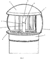
Figure 1 is a sectional view of the extractor assembly for chimneys. -
Figure 2 is a side view of the chimney extractor assembly. -
Figure 3 is a front view of the upper or lower turning ring. -
Figure 4 is a detailed view of the complete part that make up the lower and upper turning rings. -
Figure 5 is a new detailed view of the complete part that make up both the lower and upper turning rings. -
Figure 6 is a detailed view of the support ring. -
Figure 7 is a detailed view of the dome of the extractor with its six pivots. - As we can see in the referred figures, the extractor of the invention is constituted from a support ring (1) of 51 mm with a central circular neck or socket (2) supported by three conventional arms (3) designed to house by its lower part the axis of rotation (9) and the bearings (4). This support ring (1) is provided with three inserts or tabs (5) for correct fixing and coupling to the chimney pipe.
- On the support ring (1) the system formed by the lower turning ring (6) and the upper turning ring (7) in which the shaft and the bearings fit is placed. Both turning rings are joined by the vertical bar (8) that covers the shaft (9), Each upper and lower turning ring is manufactured as an independent piece, so that both incorporate a section or half (10) of the vertical bar (8) that joins both rings and covers the shaft (9), so that once both sections (15) are fitted, the skeleton of the assembly (11) Is formed without the rotation axis (9) being exposed, avoiding the drawbacks described.
- For its part, the axis of rotation (9) is circular.
- Between the upper turning piece or ring (7) and the lower turning piece or ring (6) are located conventional fins (12), but which are provided with a height of 150 mm and in a number of 18 units.
- Finally the dome (13) is assembled to the upper turning ring (7) through six pivots (14) that merge into the ring (7) to achieve a more secure connection.
- It is not considered necessary to make the present specification more extensive so that a person skilled in the art can understand the scope of the invention and the advantages derived from its use. The sizes, shapes, mechanisms, and constituent materials of the invention may be varied to adapt them to the advantages that may be derived from its specific application, as long as this does not affect the essentiality of the invention. The terms used in this report should be taken as illustrative, not limiting.
Claims (6)
- Extractor for chimneys characterized in that it comprises a support ring (1) of 51 mm in height with a circular central socket (2) supported by three conventional arms (3); a lower turning ring (6); an upper turning ring (7); a rotary axis in a circular shape (9); 18 fins and a dome (13) with six pivots (14) in which the support ring (1) incorporates three inserts or flanges (5) in order to provide greater fixation to the chimney.
- Extractor for chimneys according to the previous claim, characterized in that the lower turning ring (6) and the upper turning ring (7) constitute two different sections, each one comprising and in a single piece, a section or half of the vertical bar (8) that covers the shaft (9).
- Extractor for chimneys according to the first and second claims characterized in that the vertical bar (8) is joined by means of a socket (15) to cover the shaft (9)
- Extractor for chimneys according to the first claim, characterized in that the dome (13) incorporates six pivots (14) that fuse firmly to the upper turning ring (7).
- Extractor for chimneys according to the first claim characterized in that the 18 fins have a height of 150 mm.
- Extractor for chimneys according to the first claim, characterized in that the rotation axis (9) is round.
Priority Applications (1)
| Application Number | Priority Date | Filing Date | Title |
|---|---|---|---|
| EP20382461.0A EP3919816A1 (en) | 2020-06-01 | 2020-06-01 | Fireplace extractor |
Applications Claiming Priority (1)
| Application Number | Priority Date | Filing Date | Title |
|---|---|---|---|
| EP20382461.0A EP3919816A1 (en) | 2020-06-01 | 2020-06-01 | Fireplace extractor |
Publications (1)
| Publication Number | Publication Date |
|---|---|
| EP3919816A1 true EP3919816A1 (en) | 2021-12-08 |
Family
ID=78372140
Family Applications (1)
| Application Number | Title | Priority Date | Filing Date |
|---|---|---|---|
| EP20382461.0A Withdrawn EP3919816A1 (en) | 2020-06-01 | 2020-06-01 | Fireplace extractor |
Country Status (1)
| Country | Link |
|---|---|
| EP (1) | EP3919816A1 (en) |
Citations (4)
| Publication number | Priority date | Publication date | Assignee | Title |
|---|---|---|---|---|
| US3392659A (en) * | 1966-07-18 | 1968-07-16 | Leslie Welding Co Inc | Turbine ventilator having self-aligning bearings |
| US4303375A (en) * | 1980-05-02 | 1981-12-01 | Foglesong Robert M | Closable vane turbine ventilator |
| AU2009100921A4 (en) * | 2009-09-10 | 2009-11-05 | Csr Building Products Limited | Component for Rotor Ventilator |
| DE102013021001B3 (en) * | 2013-12-05 | 2015-02-05 | Ventfair Produktions- und Vertriebs GmbH | turbine fan |
-
2020
- 2020-06-01 EP EP20382461.0A patent/EP3919816A1/en not_active Withdrawn
Patent Citations (4)
| Publication number | Priority date | Publication date | Assignee | Title |
|---|---|---|---|---|
| US3392659A (en) * | 1966-07-18 | 1968-07-16 | Leslie Welding Co Inc | Turbine ventilator having self-aligning bearings |
| US4303375A (en) * | 1980-05-02 | 1981-12-01 | Foglesong Robert M | Closable vane turbine ventilator |
| AU2009100921A4 (en) * | 2009-09-10 | 2009-11-05 | Csr Building Products Limited | Component for Rotor Ventilator |
| DE102013021001B3 (en) * | 2013-12-05 | 2015-02-05 | Ventfair Produktions- und Vertriebs GmbH | turbine fan |
Similar Documents
| Publication | Publication Date | Title |
|---|---|---|
| JP7519684B2 (en) | Vortex Acceleration Wind Energy Tower | |
| US20110201264A1 (en) | Passive Heat Recovery & Ventilation System | |
| CN202215432U (en) | Energy-gathering recovery-type wind-driven generator | |
| US20100060010A1 (en) | Ecology friendly compound energy unit | |
| EP2123905A1 (en) | Wind collector device for power production | |
| EP3919816A1 (en) | Fireplace extractor | |
| CN101196374A (en) | Piston type energy-saving dedusting environment friendly system | |
| CN221005069U (en) | Organic solid waste coupling incinerator | |
| CN216769473U (en) | Combined air preheater | |
| CN207865355U (en) | A kind of thermoelectricity station-service waste-heat recovery device | |
| WO2010128213A2 (en) | Thermal power boiler | |
| KR102425691B1 (en) | Vertical axis wind power generator for using wind speed inside exhaust pipe | |
| US865372A (en) | Chimney. | |
| CN102357435A (en) | Centrifugal guide vane | |
| KR20140054496A (en) | Wind turbine system | |
| CN201411890Y (en) | Dwelling backflow wind and smoke exhaust device | |
| CN224049444U (en) | Fire exhaust fan filter protection structure | |
| CN2651640Y (en) | Unpowered self-suction type roof fan | |
| CN214950682U (en) | Integral three-layer coil pipe smoke two-return-stroke heat carrier furnace | |
| CN105674334B (en) | A kind of dustless self-priming environment-friendly and energy-saving furnace of closing | |
| CN210179656U (en) | Stove chimney device | |
| KR200428326Y1 (en) | Connection structure of double pipe duct for ventilation system of kitchen in multi-storey apartment | |
| CN2237805Y (en) | HEPA | |
| CN214619587U (en) | Rotary chimney of a new type of waste incinerator | |
| CN201476074U (en) | Cooking water heating energy-saving boiler |
Legal Events
| Date | Code | Title | Description |
|---|---|---|---|
| STAA | Information on the status of an ep patent application or granted ep patent |
Free format text: STATUS: UNKNOWN |
|
| PUAI | Public reference made under article 153(3) epc to a published international application that has entered the european phase |
Free format text: ORIGINAL CODE: 0009012 |
|
| STAA | Information on the status of an ep patent application or granted ep patent |
Free format text: STATUS: THE APPLICATION HAS BEEN PUBLISHED |
|
| AK | Designated contracting states |
Kind code of ref document: A1 Designated state(s): AL AT BE BG CH CY CZ DE DK EE ES FI FR GB GR HR HU IE IS IT LI LT LU LV MC MK MT NL NO PL PT RO RS SE SI SK SM TR |
|
| B565 | Issuance of search results under rule 164(2) epc |
Effective date: 20210208 |
|
| STAA | Information on the status of an ep patent application or granted ep patent |
Free format text: STATUS: THE APPLICATION IS DEEMED TO BE WITHDRAWN |
|
| 18D | Application deemed to be withdrawn |
Effective date: 20220609 |