EP3919691A1 - Work machine - Google Patents
Work machine Download PDFInfo
- Publication number
- EP3919691A1 EP3919691A1 EP20748706.7A EP20748706A EP3919691A1 EP 3919691 A1 EP3919691 A1 EP 3919691A1 EP 20748706 A EP20748706 A EP 20748706A EP 3919691 A1 EP3919691 A1 EP 3919691A1
- Authority
- EP
- European Patent Office
- Prior art keywords
- steering
- pressure oil
- pilot pressure
- pressure
- outputted
- Prior art date
- Legal status (The legal status is an assumption and is not a legal conclusion. Google has not performed a legal analysis and makes no representation as to the accuracy of the status listed.)
- Granted
Links
Images




Classifications
-
- B—PERFORMING OPERATIONS; TRANSPORTING
- B62—LAND VEHICLES FOR TRAVELLING OTHERWISE THAN ON RAILS
- B62D—MOTOR VEHICLES; TRAILERS
- B62D5/00—Power-assisted or power-driven steering
- B62D5/06—Power-assisted or power-driven steering fluid, i.e. using a pressurised fluid for most or all the force required for steering a vehicle
- B62D5/065—Power-assisted or power-driven steering fluid, i.e. using a pressurised fluid for most or all the force required for steering a vehicle characterised by specially adapted means for varying pressurised fluid supply based on need, e.g. on-demand, variable assist
-
- B—PERFORMING OPERATIONS; TRANSPORTING
- B62—LAND VEHICLES FOR TRAVELLING OTHERWISE THAN ON RAILS
- B62D—MOTOR VEHICLES; TRAILERS
- B62D5/00—Power-assisted or power-driven steering
- B62D5/06—Power-assisted or power-driven steering fluid, i.e. using a pressurised fluid for most or all the force required for steering a vehicle
- B62D5/09—Power-assisted or power-driven steering fluid, i.e. using a pressurised fluid for most or all the force required for steering a vehicle characterised by means for actuating valves
-
- B—PERFORMING OPERATIONS; TRANSPORTING
- B62—LAND VEHICLES FOR TRAVELLING OTHERWISE THAN ON RAILS
- B62D—MOTOR VEHICLES; TRAILERS
- B62D5/00—Power-assisted or power-driven steering
- B62D5/06—Power-assisted or power-driven steering fluid, i.e. using a pressurised fluid for most or all the force required for steering a vehicle
- B62D5/09—Power-assisted or power-driven steering fluid, i.e. using a pressurised fluid for most or all the force required for steering a vehicle characterised by means for actuating valves
- B62D5/091—Hydraulic steer-by-wire systems, e.g. the valve being actuated by an electric motor
-
- B—PERFORMING OPERATIONS; TRANSPORTING
- B62—LAND VEHICLES FOR TRAVELLING OTHERWISE THAN ON RAILS
- B62D—MOTOR VEHICLES; TRAILERS
- B62D5/00—Power-assisted or power-driven steering
- B62D5/06—Power-assisted or power-driven steering fluid, i.e. using a pressurised fluid for most or all the force required for steering a vehicle
- B62D5/20—Power-assisted or power-driven steering fluid, i.e. using a pressurised fluid for most or all the force required for steering a vehicle specially adapted for particular type of steering gear or particular application
- B62D5/28—Power-assisted or power-driven steering fluid, i.e. using a pressurised fluid for most or all the force required for steering a vehicle specially adapted for particular type of steering gear or particular application for pivoted bogies
-
- B—PERFORMING OPERATIONS; TRANSPORTING
- B62—LAND VEHICLES FOR TRAVELLING OTHERWISE THAN ON RAILS
- B62D—MOTOR VEHICLES; TRAILERS
- B62D5/00—Power-assisted or power-driven steering
- B62D5/06—Power-assisted or power-driven steering fluid, i.e. using a pressurised fluid for most or all the force required for steering a vehicle
- B62D5/30—Safety devices, e.g. alternate emergency power supply or transmission means to ensure steering upon failure of the primary steering means
-
- E—FIXED CONSTRUCTIONS
- E02—HYDRAULIC ENGINEERING; FOUNDATIONS; SOIL SHIFTING
- E02F—DREDGING; SOIL-SHIFTING
- E02F9/00—Component parts of dredgers or soil-shifting machines, not restricted to one of the kinds covered by groups E02F3/00 - E02F7/00
- E02F9/08—Superstructures; Supports for superstructures
- E02F9/0841—Articulated frame, i.e. having at least one pivot point between two travelling gear units
-
- E—FIXED CONSTRUCTIONS
- E02—HYDRAULIC ENGINEERING; FOUNDATIONS; SOIL SHIFTING
- E02F—DREDGING; SOIL-SHIFTING
- E02F9/00—Component parts of dredgers or soil-shifting machines, not restricted to one of the kinds covered by groups E02F3/00 - E02F7/00
- E02F9/20—Drives; Control devices
- E02F9/2004—Control mechanisms, e.g. control levers
-
- E—FIXED CONSTRUCTIONS
- E02—HYDRAULIC ENGINEERING; FOUNDATIONS; SOIL SHIFTING
- E02F—DREDGING; SOIL-SHIFTING
- E02F9/00—Component parts of dredgers or soil-shifting machines, not restricted to one of the kinds covered by groups E02F3/00 - E02F7/00
- E02F9/20—Drives; Control devices
- E02F9/22—Hydraulic or pneumatic drives
- E02F9/2221—Control of flow rate; Load sensing arrangements
- E02F9/2225—Control of flow rate; Load sensing arrangements using pressure-compensating valves
- E02F9/2228—Control of flow rate; Load sensing arrangements using pressure-compensating valves including an electronic controller
-
- E—FIXED CONSTRUCTIONS
- E02—HYDRAULIC ENGINEERING; FOUNDATIONS; SOIL SHIFTING
- E02F—DREDGING; SOIL-SHIFTING
- E02F9/00—Component parts of dredgers or soil-shifting machines, not restricted to one of the kinds covered by groups E02F3/00 - E02F7/00
- E02F9/20—Drives; Control devices
- E02F9/22—Hydraulic or pneumatic drives
- E02F9/225—Control of steering, e.g. for hydraulic motors driving the vehicle tracks
-
- E—FIXED CONSTRUCTIONS
- E02—HYDRAULIC ENGINEERING; FOUNDATIONS; SOIL SHIFTING
- E02F—DREDGING; SOIL-SHIFTING
- E02F9/00—Component parts of dredgers or soil-shifting machines, not restricted to one of the kinds covered by groups E02F3/00 - E02F7/00
- E02F9/20—Drives; Control devices
- E02F9/22—Hydraulic or pneumatic drives
- E02F9/2278—Hydraulic circuits
- E02F9/2285—Pilot-operated systems
-
- E—FIXED CONSTRUCTIONS
- E02—HYDRAULIC ENGINEERING; FOUNDATIONS; SOIL SHIFTING
- E02F—DREDGING; SOIL-SHIFTING
- E02F9/00—Component parts of dredgers or soil-shifting machines, not restricted to one of the kinds covered by groups E02F3/00 - E02F7/00
- E02F9/24—Safety devices, e.g. for preventing overload
-
- E—FIXED CONSTRUCTIONS
- E02—HYDRAULIC ENGINEERING; FOUNDATIONS; SOIL SHIFTING
- E02F—DREDGING; SOIL-SHIFTING
- E02F9/00—Component parts of dredgers or soil-shifting machines, not restricted to one of the kinds covered by groups E02F3/00 - E02F7/00
- E02F9/26—Indicating devices
- E02F9/267—Diagnosing or detecting failure of vehicles
- E02F9/268—Diagnosing or detecting failure of vehicles with failure correction follow-up actions
-
- F—MECHANICAL ENGINEERING; LIGHTING; HEATING; WEAPONS; BLASTING
- F15—FLUID-PRESSURE ACTUATORS; HYDRAULICS OR PNEUMATICS IN GENERAL
- F15B—SYSTEMS ACTING BY MEANS OF FLUIDS IN GENERAL; FLUID-PRESSURE ACTUATORS, e.g. SERVOMOTORS; DETAILS OF FLUID-PRESSURE SYSTEMS, NOT OTHERWISE PROVIDED FOR
- F15B19/00—Testing; Calibrating; Fault detection or monitoring; Simulation or modelling of fluid-pressure systems or apparatus not otherwise provided for
- F15B19/005—Fault detection or monitoring
-
- F—MECHANICAL ENGINEERING; LIGHTING; HEATING; WEAPONS; BLASTING
- F15—FLUID-PRESSURE ACTUATORS; HYDRAULICS OR PNEUMATICS IN GENERAL
- F15B—SYSTEMS ACTING BY MEANS OF FLUIDS IN GENERAL; FLUID-PRESSURE ACTUATORS, e.g. SERVOMOTORS; DETAILS OF FLUID-PRESSURE SYSTEMS, NOT OTHERWISE PROVIDED FOR
- F15B20/00—Safety arrangements for fluid actuator systems; Applications of safety devices in fluid actuator systems; Emergency measures for fluid actuator systems
-
- E—FIXED CONSTRUCTIONS
- E02—HYDRAULIC ENGINEERING; FOUNDATIONS; SOIL SHIFTING
- E02F—DREDGING; SOIL-SHIFTING
- E02F9/00—Component parts of dredgers or soil-shifting machines, not restricted to one of the kinds covered by groups E02F3/00 - E02F7/00
- E02F9/26—Indicating devices
-
- F—MECHANICAL ENGINEERING; LIGHTING; HEATING; WEAPONS; BLASTING
- F15—FLUID-PRESSURE ACTUATORS; HYDRAULICS OR PNEUMATICS IN GENERAL
- F15B—SYSTEMS ACTING BY MEANS OF FLUIDS IN GENERAL; FLUID-PRESSURE ACTUATORS, e.g. SERVOMOTORS; DETAILS OF FLUID-PRESSURE SYSTEMS, NOT OTHERWISE PROVIDED FOR
- F15B13/00—Details of servomotor systems ; Valves for servomotor systems
- F15B13/02—Fluid distribution or supply devices characterised by their adaptation to the control of servomotors
- F15B13/04—Fluid distribution or supply devices characterised by their adaptation to the control of servomotors for use with a single servomotor
- F15B13/042—Fluid distribution or supply devices characterised by their adaptation to the control of servomotors for use with a single servomotor operated by fluid pressure
- F15B13/043—Fluid distribution or supply devices characterised by their adaptation to the control of servomotors for use with a single servomotor operated by fluid pressure with electrically-controlled pilot valves
- F15B13/0433—Fluid distribution or supply devices characterised by their adaptation to the control of servomotors for use with a single servomotor operated by fluid pressure with electrically-controlled pilot valves the pilot valves being pressure control valves
-
- F—MECHANICAL ENGINEERING; LIGHTING; HEATING; WEAPONS; BLASTING
- F15—FLUID-PRESSURE ACTUATORS; HYDRAULICS OR PNEUMATICS IN GENERAL
- F15B—SYSTEMS ACTING BY MEANS OF FLUIDS IN GENERAL; FLUID-PRESSURE ACTUATORS, e.g. SERVOMOTORS; DETAILS OF FLUID-PRESSURE SYSTEMS, NOT OTHERWISE PROVIDED FOR
- F15B2211/00—Circuits for servomotor systems
- F15B2211/30—Directional control
- F15B2211/32—Directional control characterised by the type of actuation
- F15B2211/327—Directional control characterised by the type of actuation electrically or electronically
-
- F—MECHANICAL ENGINEERING; LIGHTING; HEATING; WEAPONS; BLASTING
- F15—FLUID-PRESSURE ACTUATORS; HYDRAULICS OR PNEUMATICS IN GENERAL
- F15B—SYSTEMS ACTING BY MEANS OF FLUIDS IN GENERAL; FLUID-PRESSURE ACTUATORS, e.g. SERVOMOTORS; DETAILS OF FLUID-PRESSURE SYSTEMS, NOT OTHERWISE PROVIDED FOR
- F15B2211/00—Circuits for servomotor systems
- F15B2211/30—Directional control
- F15B2211/32—Directional control characterised by the type of actuation
- F15B2211/329—Directional control characterised by the type of actuation actuated by fluid pressure
-
- F—MECHANICAL ENGINEERING; LIGHTING; HEATING; WEAPONS; BLASTING
- F15—FLUID-PRESSURE ACTUATORS; HYDRAULICS OR PNEUMATICS IN GENERAL
- F15B—SYSTEMS ACTING BY MEANS OF FLUIDS IN GENERAL; FLUID-PRESSURE ACTUATORS, e.g. SERVOMOTORS; DETAILS OF FLUID-PRESSURE SYSTEMS, NOT OTHERWISE PROVIDED FOR
- F15B2211/00—Circuits for servomotor systems
- F15B2211/30—Directional control
- F15B2211/355—Pilot pressure control
-
- F—MECHANICAL ENGINEERING; LIGHTING; HEATING; WEAPONS; BLASTING
- F15—FLUID-PRESSURE ACTUATORS; HYDRAULICS OR PNEUMATICS IN GENERAL
- F15B—SYSTEMS ACTING BY MEANS OF FLUIDS IN GENERAL; FLUID-PRESSURE ACTUATORS, e.g. SERVOMOTORS; DETAILS OF FLUID-PRESSURE SYSTEMS, NOT OTHERWISE PROVIDED FOR
- F15B2211/00—Circuits for servomotor systems
- F15B2211/30—Directional control
- F15B2211/36—Pilot pressure sensing
-
- F—MECHANICAL ENGINEERING; LIGHTING; HEATING; WEAPONS; BLASTING
- F15—FLUID-PRESSURE ACTUATORS; HYDRAULICS OR PNEUMATICS IN GENERAL
- F15B—SYSTEMS ACTING BY MEANS OF FLUIDS IN GENERAL; FLUID-PRESSURE ACTUATORS, e.g. SERVOMOTORS; DETAILS OF FLUID-PRESSURE SYSTEMS, NOT OTHERWISE PROVIDED FOR
- F15B2211/00—Circuits for servomotor systems
- F15B2211/50—Pressure control
- F15B2211/575—Pilot pressure control
-
- F—MECHANICAL ENGINEERING; LIGHTING; HEATING; WEAPONS; BLASTING
- F15—FLUID-PRESSURE ACTUATORS; HYDRAULICS OR PNEUMATICS IN GENERAL
- F15B—SYSTEMS ACTING BY MEANS OF FLUIDS IN GENERAL; FLUID-PRESSURE ACTUATORS, e.g. SERVOMOTORS; DETAILS OF FLUID-PRESSURE SYSTEMS, NOT OTHERWISE PROVIDED FOR
- F15B2211/00—Circuits for servomotor systems
- F15B2211/60—Circuit components or control therefor
- F15B2211/63—Electronic controllers
- F15B2211/6303—Electronic controllers using input signals
- F15B2211/6306—Electronic controllers using input signals representing a pressure
- F15B2211/6316—Electronic controllers using input signals representing a pressure the pressure being a pilot pressure
-
- F—MECHANICAL ENGINEERING; LIGHTING; HEATING; WEAPONS; BLASTING
- F15—FLUID-PRESSURE ACTUATORS; HYDRAULICS OR PNEUMATICS IN GENERAL
- F15B—SYSTEMS ACTING BY MEANS OF FLUIDS IN GENERAL; FLUID-PRESSURE ACTUATORS, e.g. SERVOMOTORS; DETAILS OF FLUID-PRESSURE SYSTEMS, NOT OTHERWISE PROVIDED FOR
- F15B2211/00—Circuits for servomotor systems
- F15B2211/60—Circuit components or control therefor
- F15B2211/63—Electronic controllers
- F15B2211/6303—Electronic controllers using input signals
- F15B2211/6336—Electronic controllers using input signals representing a state of the output member, e.g. position, speed or acceleration
-
- F—MECHANICAL ENGINEERING; LIGHTING; HEATING; WEAPONS; BLASTING
- F15—FLUID-PRESSURE ACTUATORS; HYDRAULICS OR PNEUMATICS IN GENERAL
- F15B—SYSTEMS ACTING BY MEANS OF FLUIDS IN GENERAL; FLUID-PRESSURE ACTUATORS, e.g. SERVOMOTORS; DETAILS OF FLUID-PRESSURE SYSTEMS, NOT OTHERWISE PROVIDED FOR
- F15B2211/00—Circuits for servomotor systems
- F15B2211/60—Circuit components or control therefor
- F15B2211/63—Electronic controllers
- F15B2211/6303—Electronic controllers using input signals
- F15B2211/6346—Electronic controllers using input signals representing a state of input means, e.g. joystick position
-
- F—MECHANICAL ENGINEERING; LIGHTING; HEATING; WEAPONS; BLASTING
- F15—FLUID-PRESSURE ACTUATORS; HYDRAULICS OR PNEUMATICS IN GENERAL
- F15B—SYSTEMS ACTING BY MEANS OF FLUIDS IN GENERAL; FLUID-PRESSURE ACTUATORS, e.g. SERVOMOTORS; DETAILS OF FLUID-PRESSURE SYSTEMS, NOT OTHERWISE PROVIDED FOR
- F15B2211/00—Circuits for servomotor systems
- F15B2211/60—Circuit components or control therefor
- F15B2211/635—Circuits providing pilot pressure to pilot pressure-controlled fluid circuit elements
- F15B2211/6355—Circuits providing pilot pressure to pilot pressure-controlled fluid circuit elements having valve means
-
- F—MECHANICAL ENGINEERING; LIGHTING; HEATING; WEAPONS; BLASTING
- F15—FLUID-PRESSURE ACTUATORS; HYDRAULICS OR PNEUMATICS IN GENERAL
- F15B—SYSTEMS ACTING BY MEANS OF FLUIDS IN GENERAL; FLUID-PRESSURE ACTUATORS, e.g. SERVOMOTORS; DETAILS OF FLUID-PRESSURE SYSTEMS, NOT OTHERWISE PROVIDED FOR
- F15B2211/00—Circuits for servomotor systems
- F15B2211/60—Circuit components or control therefor
- F15B2211/67—Methods for controlling pilot pressure
-
- F—MECHANICAL ENGINEERING; LIGHTING; HEATING; WEAPONS; BLASTING
- F15—FLUID-PRESSURE ACTUATORS; HYDRAULICS OR PNEUMATICS IN GENERAL
- F15B—SYSTEMS ACTING BY MEANS OF FLUIDS IN GENERAL; FLUID-PRESSURE ACTUATORS, e.g. SERVOMOTORS; DETAILS OF FLUID-PRESSURE SYSTEMS, NOT OTHERWISE PROVIDED FOR
- F15B2211/00—Circuits for servomotor systems
- F15B2211/80—Other types of control related to particular problems or conditions
- F15B2211/86—Control during or prevention of abnormal conditions
- F15B2211/862—Control during or prevention of abnormal conditions the abnormal condition being electric or electronic failure
-
- F—MECHANICAL ENGINEERING; LIGHTING; HEATING; WEAPONS; BLASTING
- F15—FLUID-PRESSURE ACTUATORS; HYDRAULICS OR PNEUMATICS IN GENERAL
- F15B—SYSTEMS ACTING BY MEANS OF FLUIDS IN GENERAL; FLUID-PRESSURE ACTUATORS, e.g. SERVOMOTORS; DETAILS OF FLUID-PRESSURE SYSTEMS, NOT OTHERWISE PROVIDED FOR
- F15B2211/00—Circuits for servomotor systems
- F15B2211/80—Other types of control related to particular problems or conditions
- F15B2211/86—Control during or prevention of abnormal conditions
- F15B2211/862—Control during or prevention of abnormal conditions the abnormal condition being electric or electronic failure
- F15B2211/8623—Electric supply failure
-
- F—MECHANICAL ENGINEERING; LIGHTING; HEATING; WEAPONS; BLASTING
- F15—FLUID-PRESSURE ACTUATORS; HYDRAULICS OR PNEUMATICS IN GENERAL
- F15B—SYSTEMS ACTING BY MEANS OF FLUIDS IN GENERAL; FLUID-PRESSURE ACTUATORS, e.g. SERVOMOTORS; DETAILS OF FLUID-PRESSURE SYSTEMS, NOT OTHERWISE PROVIDED FOR
- F15B2211/00—Circuits for servomotor systems
- F15B2211/80—Other types of control related to particular problems or conditions
- F15B2211/86—Control during or prevention of abnormal conditions
- F15B2211/863—Control during or prevention of abnormal conditions the abnormal condition being a hydraulic or pneumatic failure
-
- F—MECHANICAL ENGINEERING; LIGHTING; HEATING; WEAPONS; BLASTING
- F15—FLUID-PRESSURE ACTUATORS; HYDRAULICS OR PNEUMATICS IN GENERAL
- F15B—SYSTEMS ACTING BY MEANS OF FLUIDS IN GENERAL; FLUID-PRESSURE ACTUATORS, e.g. SERVOMOTORS; DETAILS OF FLUID-PRESSURE SYSTEMS, NOT OTHERWISE PROVIDED FOR
- F15B2211/00—Circuits for servomotor systems
- F15B2211/80—Other types of control related to particular problems or conditions
- F15B2211/86—Control during or prevention of abnormal conditions
- F15B2211/863—Control during or prevention of abnormal conditions the abnormal condition being a hydraulic or pneumatic failure
- F15B2211/8633—Pressure source supply failure
-
- F—MECHANICAL ENGINEERING; LIGHTING; HEATING; WEAPONS; BLASTING
- F15—FLUID-PRESSURE ACTUATORS; HYDRAULICS OR PNEUMATICS IN GENERAL
- F15B—SYSTEMS ACTING BY MEANS OF FLUIDS IN GENERAL; FLUID-PRESSURE ACTUATORS, e.g. SERVOMOTORS; DETAILS OF FLUID-PRESSURE SYSTEMS, NOT OTHERWISE PROVIDED FOR
- F15B2211/00—Circuits for servomotor systems
- F15B2211/80—Other types of control related to particular problems or conditions
- F15B2211/86—Control during or prevention of abnormal conditions
- F15B2211/863—Control during or prevention of abnormal conditions the abnormal condition being a hydraulic or pneumatic failure
- F15B2211/8636—Circuit failure, e.g. valve or hose failure
-
- F—MECHANICAL ENGINEERING; LIGHTING; HEATING; WEAPONS; BLASTING
- F15—FLUID-PRESSURE ACTUATORS; HYDRAULICS OR PNEUMATICS IN GENERAL
- F15B—SYSTEMS ACTING BY MEANS OF FLUIDS IN GENERAL; FLUID-PRESSURE ACTUATORS, e.g. SERVOMOTORS; DETAILS OF FLUID-PRESSURE SYSTEMS, NOT OTHERWISE PROVIDED FOR
- F15B2211/00—Circuits for servomotor systems
- F15B2211/80—Other types of control related to particular problems or conditions
- F15B2211/875—Control measures for coping with failures
- F15B2211/8752—Emergency operation mode, e.g. fail-safe operation mode
-
- F—MECHANICAL ENGINEERING; LIGHTING; HEATING; WEAPONS; BLASTING
- F15—FLUID-PRESSURE ACTUATORS; HYDRAULICS OR PNEUMATICS IN GENERAL
- F15B—SYSTEMS ACTING BY MEANS OF FLUIDS IN GENERAL; FLUID-PRESSURE ACTUATORS, e.g. SERVOMOTORS; DETAILS OF FLUID-PRESSURE SYSTEMS, NOT OTHERWISE PROVIDED FOR
- F15B2211/00—Circuits for servomotor systems
- F15B2211/80—Other types of control related to particular problems or conditions
- F15B2211/875—Control measures for coping with failures
- F15B2211/8757—Control measures for coping with failures using redundant components or assemblies
Definitions
- the present invention relates to a work machine to actuate a hydraulic actuator by an electric signal outputted from a steering device.
- An electric operating device including an electric lever to output an electric signal responding to an amount of the operation, a proportional solenoid pressure reducing valve to generate a pilot pressure in accordance with the electric signal outputted from the electric lever, and a directional control valve to control an opening by the pilot pressure generated by the proportional solenoid pressure reducing valve has heretofore been known.
- Patent Literature 1 In an electric operating device described in Patent Literature 1, for example, a main operating device and a sub operating device are provided in parallel, and a work machine can be operated safely by switching the main operating device to the sub operating device in a case where something goes wrong with the main operating device.
- Patent Literature 1 Japanese Unexamined Patent Application Publication No. 2016-114129
- Patent Literature 1 An electric operating device in Patent Literature 1 can be applied to a steering circuit in a work machine, for example. If such an electric operating device is applied to a wheel-type work machine that moves at a high speed, however, there is the problem of causing an inoperable state while an operator who recognize a malfunction shifts from a main operating device to a sub operating device.
- An object of the present invention is to provide a technology of enhancing switching responsiveness in a work machine that can be operated continuously by switching a steering circuit in a case where a malfunction occurs.
- an embodiment of a work machine according to the present invention in the work machine, comprises:
- the present invention makes it possible to enhance switching responsiveness in a work machine that can be operated continuously by switching a steering circuit in a case where a malfunction occurs.
- problems, configurations, and effects other than those described above will be obvious in the descriptions of the following embodiments.
- Embodiments of a wheel loader that is an example of a work vehicle according to the present invention are hereunder explained in reference to the drawings.
- the same reference numerals are given to the same configurations in respective embodiments, and duplicate description is omitted.
- FIG. 1 is a side view of a wheel loader 100 according to an embodiment of the present invention.
- the wheel loader 100 that is an example of a work machine includes a lift arm 101, a bucket 102, a front frame 104 having a pair of left and right front wheels 103, and the like, a cab 105, and a rear frame 107 having a pair of left and right rear wheels 106, and the like.
- the front wheels 103 and the rear wheels 106 are driven by an engine mounted on the wheel loader 100. More specifically, the driving force of the engine is changed by a transmission via a torque converter and further is transmitted to the front wheels 103 and the rear wheels 106 via a propeller shaft and an axle.
- the lift arm 101 moves rotationally in the vertical direction (looks up and down) by actuating of a lift arm cylinder 108.
- the bucket 102 moves rotationally in the vertical direction (clouds or dumps) by actuating of a bucket cylinder 109.
- the lift arm 101, the bucket 102, the lift arm cylinder 108, and the bucket cylinder 109 constitute a front work device.
- the front frame 104 and the rear frame 107 are rotatably connected to each other by a connecting shaft 110.
- the front frame 104 and the rear frame 107 are connected by a pair of steering cylinders 111L and 111R provided on the left and right of the connecting shaft 110.
- the paired left and right steering cylinders 111L and 111R correspond to a "steering actuator" according to the present invention.
- the front frame 104 bends around the connecting shaft 110 left and right with respect to the rear frame 107 by expanding one of the paired steering cylinders 111L and 111R and contracting the other by a steering circuit 10 that will be described later. Accordingly, the relative mounting angle between the front frame 104 and the rear frame 107 changes, and the vehicle body bends and steers.
- the wheel loader 100 is of an articulated type in which the front frame 104 and the rear frame 107 are bent around the connecting shaft 110.
- a steering lever 11 (refer to FIG. 2 ) to expand and contract the steering cylinders 111L and 111R is installed in the cab 105.
- the steering lever 11 corresponds to a steering device. Although they are not shown in the figures, in the cab 105, an arm operation lever to expand and contract the lift arm cylinder 108, a bucket operation lever to expand and contract the bucket cylinder 109, an accelerator pedal to adjust an engine speed, a brake pedal to brake the front wheels 103 and the rear wheels 106, and other are installed.
- a notification device 24 (refer to FIG. 2 ) to notify various information to a operator is installed.
- the notification device 24 is a display, a warning lamp, a speaker, and the like, for example. That is, a operator in the cab 105 can operate the steering lever 11, etc. while checking the notification device 24.
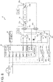
- FIG. 2 is a block diagram of the steering circuit 10 in the wheel loader 100.
- the steering circuit 10 is a device to actuate (expand and contract) the steering cylinders 111L and 111R in accordance with the operation of a operator to the steering lever 11.
- the steering circuit 10 mainly includes a steering lever 11, a controller 12, a pressure source 13, proportional solenoid pressure reducing valves 14a and 14b, diodes 15a and 15b, relays 16a and 16b, a power source 17, solenoid valves 18a and 18b, switching valves 20a and 20b, a directional control valve 21, first pressure sensors 22a and 22b, and second pressure sensors 23a and 23b.
- the steering lever 11 outputs a voltage value (steering signal) corresponding to the amount of the operation by an operator to the controller 12 and the diode 15a or 15b through OUT1 or OUT2.
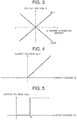
- FIG. 3 is a graph showing a relationship between an amount of the operation of the steering lever 11 and an output voltage V.
- a positive voltage is outputted to OUT1 and a negative voltage is outputted to OUT2.
- a negative voltage is outputted to OUT1 and a positive voltage is outputted to OUT2.
- the absolute values of the voltages outputted to OUT1 and OUT2 increase.
- the controller 12 controls the operations of the proportional solenoid pressure reducing valves 14a and 14b, the switching valves 20a and 20b, and the notification device 24 on the basis of a voltage value outputted from the steering lever 11, measured voltages Va1 measured by the first pressure sensors 22a and 22b, and measured voltages Va2 measured by the second pressure sensors 23a and 23b.
- the controller 12 mainly includes a main controller 12a, a sub controller 12b, and a memory 12c, for example.
- the controller 12 includes a CPU (Central Processing Unit), a ROM (Read Only Memory), a RAM (Random Access Memory), and the like. Then respective processes that will be described later are realized by the CPU reading and executing programs from the ROM and the RAM.
- the main controller 12a adjusts the opening of the proportional solenoid pressure reducing valve 14a or 14b in accordance with a voltage value outputted from the steering lever 11.
- the sub controller 12b switches the state of the switching valve 20a or 20b on the basis of a voltage value outputted from the steering lever 11, a measured voltage Va1 measured by the first pressure sensor 22a or 22b, a measured voltage Va2 measured by the second pressure sensor 23a or 23b, and health information obtained from the main controller 12a; and notifies a malfunction in the steering circuit 10 through the notification device 24.
- the memory 12c stores input voltage-target pilot pressure tables (conversion tables) 31a and 31b and target pilot pressure-target solenoid current tables 32a and 32b shown in FIG. 6 .
- FIG. 6 is a view showing processing of the main controller 12a.
- the input voltage-target pilot pressure table 31a or 31b shows a relationship between a voltage value outputted from the steering lever 11 and a target pressure Pt1 of a first pilot pressure oil to be outputted from the proportional solenoid pressure reducing valve 14a or 14b.
- the target pilot pressure-target solenoid current table 32a or 32b shows a relationship between the target pressure Pt1 specified by the input voltage-target pilot pressure table 31a or 31b and a target current value of a PWM signal to adjust the opening of the proportional solenoid pressure reducing valve 14a or 14b.
- the main controller 12a calculates a target pressure Pt1 corresponding to a voltage value outputted from OUT1 in the steering lever 11 on the basis of the input voltage-target pilot pressure table 31a. Successively, the main controller 12a calculates a target current value corresponding to the calculated target pressure Pt1 on the basis of the target pilot pressure-target solenoid current table 32a. Then the main controller 12a controls a PWM driver 33a and outputs a PWM signal corresponding to the target current value to the proportional solenoid pressure reducing valve 14a.
- the proportional solenoid pressure reducing valve 14a opens in a case where the voltage value of OUT1 is higher than a predetermined value and closes in a case where the voltage value of OUT1 is lower than a predetermined value (including a negative voltage value). Further, the opening of the proportional solenoid pressure reducing valve 14a increases as the voltage value of OUT1 increases.
- a method of adjusting the opening of the proportional solenoid pressure reducing valve 14b by using a voltage value outputted from OUT2 in the steering lever 11, the input voltage-target pilot pressure table 31b, the target pilot pressure-target solenoid current table 32b, and a PWM driver 33b.
- the pressure source 13 supplies a pressure oil with a pilot primary pressure to the proportional solenoid pressure reducing valves 14a and 14b and the solenoid valves 18a and 18b.
- the pressure source 13 includes a tank to store a hydraulic oil, a hydraulic pump to pump the hydraulic oil stored in the tank, and the like, for example.
- the pilot primary pressure is set so as to be higher than the maximum value of the target pressure Pt1 of the first pilot pressure oil and the maximum value of a target pressure Pt2 of a second pilot pressure oil that will be described later.
- the proportional solenoid pressure reducing valve 14a or 14b reduces the pilot primary pressure to the target pressure Pt1 in accordance with the PWM signal outputted from the main controller 12a; and outputs the first pilot pressure oil reduced to the target pressure Pt1 to the switching valve 20a or 20b. That is, the proportional solenoid pressure reducing valve 14a or 14b outputs the first pilot pressure oil with a higher pressure as the current value of the PWM signal increases. In other words, the first pilot pressure oil is outputted from one of the proportional solenoid pressure reducing valves 14a and 14b at a pressure responding to the positive steering signal in the paired steering signals R and L outputted from the steering lever 11.
- FIG. 4 is a graph showing a relationship between an input voltage (OUT1 or OUT2) and an output voltage in the diode 15a or 15b.
- the diode 15a passes the steering signal R of OUT1 and the diode 15b does not pass the steering signal L of OUT2.
- the diode 15a does not pass the steering signal R of OUT 1 and the diode 15b passes the steering signal L of OUT2.
- the diode 15a or 15b passes only the steering signal of a positive voltage value, of the steering signals outputted from the steering lever 11; and does not pass the steering signal of a negative voltage value. Further, as the voltage value outputted from OUT1 or OUT2 increases, the voltage value outputted from the diode 15a or 15b increases. That is, the diode 15a or 15b passes only a steering signal corresponding to the steering lever 11 operated in a predetermined direction.
- the relay 16a or 16b applies a voltage (instruction signal) supplied from the power source 17 to the solenoid valve 18a or 18b according to the diode 15a or 15b having passed a steering signal.
- FIG. 5 is a graph showing a relationship between an input voltage value and an output voltage value in the relay 16a or 16b. That is, the relay 16a or 16b outputs an instruction signal of a predetermined voltage value according to the diode 15a or 15b having passed a steering signal of a predetermined voltage value VO or higher.
- the instruction signal is a signal for causing the solenoid valve 18a or 18b to output the second pilot pressure oil with a predetermined pressure.
- the solenoid valve 18a or 18b reduces the pilot primary pressure supplied from the pressure source 13 to a predetermined target pressure Pt2; and outputs a second pilot pressure oil reduced to the target pressure Pt2 to the switching valve 20a or 20b while the instruction signal is outputted from the relay 16a or 16b.
- the solenoid valve 18a or 18b does not output a second pilot pressure oil while the instruction signal is not outputted from the relay 16a or 16b.
- the switching valve 20a or 20b outputs only one of the first pilot pressure oil supplied from the proportional solenoid pressure reducing valve 14a or 14b and the second pilot pressure oil supplied from the solenoid valve 18a or 18b to a pilot chamber 21a or 21b in the directional control valve 21. More specifically, the switching valves 20a and 20b are configured so as to be switchable between a first state of passing the first pilot pressure oil and not passing the second pilot pressure oil and a second state of not passing the first pilot pressure oil and passing the second pilot pressure oil.
- the switching valves 20a and 20b output only one of the first pilot pressure oil and the second pilot pressure oil in accordance with the control of the sub controller 12b.
- the switching valves 20a and 20b may also be configured so as to: be urged to the second state (initial state) by urging members such as springs; and maintain the first state only while an instruction signal is outputted from the sub controller 12b.
- the directional control valve 21 supplies a hydraulic oil to the steering cylinders 111L and 111R in accordance with a pilot pressure oil supplied to the pilot chamber 21a or 21b.
- the directional control valve 21 is a proportional valve in which a supply amount (supply speed) of the hydraulic oil supplied to the steering cylinders 111L and 111R increases as the pressure of the supplied pilot pressure oil increases.
- the directional control valve 21 is configured so as to be switchable to the states A, B, and C.
- the directional control valve 21 is maintained in the state A (initial state) while the pilot pressure oil is not supplied to both the pilot chambers 21a and 21b.
- the directional control valve 21 in the state A keeps the steering cylinders 111L and 111R in a stationary state. That is, the steering angle of the wheel loader 100 is maintained while the directional control valve 21 is in the state A.
- the pilot pressure oil is supplied to the pilot chamber 21a. Accordingly, the directional control valve 21 is switched from the state A to the state B.
- the directional control valve 21 in the state B supplies the hydraulic oil to the bottom chamber of the steering cylinder 111L and the rod chamber of the steering cylinder 111R.
- the hydraulic oil in the rod chamber of the steering cylinder 111L and the bottom chamber of the steering cylinder 111R is discharged to a tank (not shown in the figures). Accordingly, the steering cylinder 111L expands and the steering cylinder 111R contracts. As a result, the front frame 104 bends to the right with respect to the rear frame 107 and the steering of the wheel loader 100 turns to the right.
- the pilot pressure oil is supplied to the pilot chamber 21b. Accordingly, the directional control valve 21 is switched from the state A to the state C.
- the directional control valve 21 in the state C supplies the hydraulic oil to the rod chamber of the steering cylinder 111L and the bottom chamber of the steering cylinder 111R.
- the hydraulic oil in the bottom chamber of the steering cylinder 111L and the rod chamber of the steering cylinder 111R is discharged to a tank (not shown in the figures). Accordingly, the steering cylinder 111L contracts and the steering cylinder 111R expands. As a result, the front frame 104 bends to the left with respect to the rear frame 107 and the steering of the wheel loader 100 turns to the left.
- the first pressure sensor 22a or 22b measures the pressure value of the pilot pressure oil outputted from the switching valve 20a or 20b, in other words the pilot pressure oil supplied to the pilot chamber 21a or 21b in the directional control valve 21; and outputs the pressure value as a pressure Pa1 to the controller 12.
- the second pressure sensor 23a or 23b measures the pressure value of the second pilot pressure oil outputted from the solenoid valve 18a or 18b, in other words the second pilot pressure oil supplied to the switching valve 20a or 20b; and outputs the pressure value as a pressure Pa2 to the controller 12.
- the circuit ranging from the steering lever 11 to the directional control valve 21 via the main controller 12a, the proportional solenoid pressure reducing valves 14a and 14b, and the switching valves 20a and 20b in the first state is referred to as a "main circuit” and the circuit ranging from the steering lever 11 to the solenoid valves 18a and 18b via the diodes 15a and 15b and the relays 16a and 16b is referred to as a "sub circuit".
- the sub circuit may further include the circuit ranging from the solenoid valves 18a and 18b to the directional control valve 21 via the switching valves 20a and 20b in the second state.
- FIG. 7 is a flowchart of malfunction detection processing.
- the sub controller 12b outputs an instruction signal to the switching valves 20a and 20b. In other words, the switching valves 20a and 20b are maintained in the first state.
- the sub controller 12b monitors the output of a steering signal from the steering lever 11 (S11). Then, the sub controller 12b calculates a target pressure Pt1 of the first pilot pressure oil (S12) on the basis of the voltage value of the steering signal and the input voltage-target pilot pressure table 31a or 31b according to the steering signal being outputted from the steering lever 11 (S11: Yes). Further, the sub controller 12b obtains a pressure Pa1 measured by the first pressure sensor 22a or 22b (S13).
- the switching valves 20a and 20b are in the first state, and hence the pressure Pa1 means the pressure value of the first pilot pressure oil.
- the sub controller 12b calculates a target pressure Pt1 corresponding to the voltage value of the steering signal R of OUT1 on the basis of the input voltage-target pilot pressure table 31a (S12); and obtains a pressure Pa1 of the first pilot pressure oil supplied to the pilot chamber 21a from the first pressure sensor 22a (S13).
- the sub controller 12b calculates a target pressure Pt1 corresponding to the voltage value of the steering signal L of OUT2 on the basis of the input voltage-target pilot pressure table 31b (S12); and obtains a pressure Pa1 of the first pilot pressure oil supplied to the pilot chamber 21b from the first pressure sensor 22b (S13).
- the sub controller 12b compares the target pressure Pt1 with the pressure Pa1 (S14). Then, the sub controller 12b detects a malfunction in the main circuit and switches the solenoid valve 18a or 18b from the first state to the second state (S15) according to judging that the difference between the target pressure Pt1 and the pressure Pa1 is a threshold value or more (S14: Yes). That is, the sub controller 12b stops the instruction signal that continues to be outputted to the switching valves 20a and 20b. Accordingly, the switching valves 20a and 20b are switched from the first state to the second state by urging members.
- the sub controller 12b notifies a malfunction in the main circuit to a operator through the notification device 24 (S16) according to detecting the malfunction in the main circuit (S14: Yes).
- a specific notification method is not particularly limited but a message may be displayed in a display, a warning lamp may be lit or blinked, or an alarm may be outputted from a speaker, for example. The same applies to the notification methods at Steps S18 and S21 that will be described later.
- the sub controller 12b judges that the main circuit operates normally and advances to the processes after Step S17 without executing the processes of Steps S15 and S16 according to judging that the difference between the target pressure Pt1 and the pressure Pa1 is less than a threshold value (S14: No). That is, the switching valves 20a and 20b are maintained in the first state. Successively, the sub controller 12b compares the steering signal R outputted from OUT1 with the steering signal L outputted from OUT2 (S17).
- the ideal values of the steering signals R and L are voltage values the absolute values of which are the same and the signs of which are inverted. That is, theoretically the sum of the voltage values of the steering signals R and L is zero.
- the sub controller 12b may judge that the steering signals R and L are normal in a case where the difference between the absolute values of the steering signals R and L is less than a predetermined value and the signs of the steering signals R and L are inverted, for example.
- the sub controller 12b may judge that the steering signals R and L are abnormal in a case where the difference between the absolute values of the steering signals R and L is a predetermined value or more or the signs of the steering signals R and L are the same.
- the sub controller 12b notifies a malfunction in the steering lever 11 through the notification device 24 (S18) according to judging that the steering signals R and L are abnormal (S17: No).
- the sub controller 12b advances to the processes after Step S19 without executing Step S18 according to judging that the steering signals R and L are normal (S17: Yes).
- the sub controller 12b obtains the pressure Pa2 of the second pilot pressure oil from the second pressure sensor 23a or 23b (S19). Successively, the sub controller 12b judges whether or not the pressure Pa2 is less than a predetermined value (S20). More specifically, the sub controller 12b judges whether or not the pressure Pa2 obtained from the second pressure sensor 23a is less than a predetermined value in a case where the steering signal R is a positive voltage value. On the other hand, the sub controller 12b judges whether or not the pressure Pa2 obtained from the second pressure sensor 23b is less than a predetermined value in a case where the steering signal L is a positive voltage value.
- the sub controller 12b notifies a malfunction in the sub circuit through the notification device 24 (S21) according to judging that the pressure Pa2 is less than a predetermined value (S20: Yes). On the other hand, the sub controller 12b returns to S11 and continues the processes without executing the process of S21 according to judging that the pressure Pa2 is a predetermined value or more (S20: No). That is, the malfunction detection processing in FIG. 7 continues until some malfunction is detected in the steering circuit 10.
- both the first pilot pressure oil and the second pilot pressure oil are always supplied to the switching valves 20a and 20b in parallel. Therefore, in a case where a malfunction in the main circuit is detect and the switching valve 20a or 20b is switched from the first state to the second state (S14: Yes), the second pilot pressure oil is supplied instantly to the pilot chamber 21a or 21b. That is, the wheel loader 100 can continue to turn in the operating direction of the steering lever 11 even if a malfunction occurs in the main circuit. That is, high responsiveness can be achieved at the time of switching from the main circuit to the sub circuit.
- the above embodiment therefore is configured so that the second pilot pressure oil may be supplied to the switching valve 20a or 20b only if a voltage value inputted to the relay 16a or 16b is a predetermined voltage value V0 or larger. Accordingly, in a case where the tilt amount of the steering lever 11 is small (in other words, the steering of the wheel loader 100 is fixed), the second pilot pressure oil is not supplied to the directional control valve 21 even if the switching valve 20a or 20b is switched to the second state. As a result, the steering angle of the wheel loader 100 can be prevented from increasing at the timing of causing a malfunction in the main circuit.
- the rate of malfunction in the sub circuit can be lower than that in the main circuit. Accordingly, in a case where a malfunction occurs in the main circuit, the sub circuit can be functioned without fail.
- a operator can stop the wheel loader 100 safely by switching the switching valve 20a or 20b and continuing to turn the wheel loader 100 and also by notifying a malfunction in the main circuit.
- a malfunction in the main circuit in a case where abnormalities in the steering lever 11 and the sub circuit are detected (S17: No/S20: Yes), those are also notified to a operator (S18/S21), and hence the degree of safety in the wheel loader 100 improves further.
- a concrete method for detecting a malfunction in the main circuit is not limited to Step S14 in FIG. 7 .
- the wheel loader 100 may include an expansion and contraction sensor to detect an expansion and contraction amount of the steering cylinder 111L or 111R. Then, the sub controller 12b may detect a malfunction in the main circuit by consistency between a steering signal outputted from the steering lever 11 and an expansion and contraction amount of the steering cylinder 111L or 111R detected by the expansion and contraction sensor.
- a malfunction in a main circuit refers to a situation where a pressure (output) of the first pilot pressure oil corresponding to a steering signal (input) deviates from an allowable range like at Step S14.
- a malfunction in the sub circuit refers to a situation where a pressure (output) of the second pilot pressure oil corresponding to a steering signal (input) deviates from an allowable range like at Step S19.
- a malfunction in the steering lever 11 refers to a situation where a steering signal R or L (output) corresponding to a tilt (input) of the steering lever 11 does not match the original characteristic (absolute values match and signs are inverted) like at Step S17.
- the diodes 15a and 15b and the relays 16a and 16b are examples constituting an amplifier circuit that amplifies and outputs a steering signal as an instruction signal.
- a concrete configuration of an amplifier circuit is not limited to the example of FIG. 2 .
- the steering circuit 10 may include amplifier circuits 40a and 40b shown in FIG. 8 instead of the amplifier circuit including the diodes 15a and 15b and the relays 16a and 16b.
- FIG. 8 is a block diagram of a steering circuit 10 including the amplifier circuits 40a and 40b.
- the amplifier circuit 40a is a non-inverting amplifier circuit including an operational amplifier 41a and resistors 42a and 43a.
- the amplifier circuit 40b is a non-inverting amplifier circuit including an operational amplifier 41b and resistors 42b and 43b.
- a steering signal outputted from the steering lever 11 is inputted to an input terminal VIN and outputted as an amplified instruction signal from an output terminal VOUT to the solenoid valve 18a or 18b.
- a concrete example of a work machine is not limited to the wheel loader 100 and may also be an excavator car, a dump truck, and the like. Furthermore, in the above embodiment, a steering wheel capable of outputting a voltage may be used instead of the steering lever 11.
Landscapes
- Engineering & Computer Science (AREA)
- General Engineering & Computer Science (AREA)
- Mechanical Engineering (AREA)
- Chemical & Material Sciences (AREA)
- Mining & Mineral Resources (AREA)
- Civil Engineering (AREA)
- Structural Engineering (AREA)
- Transportation (AREA)
- Combustion & Propulsion (AREA)
- Physics & Mathematics (AREA)
- Fluid Mechanics (AREA)
- Analytical Chemistry (AREA)
- Operation Control Of Excavators (AREA)
- Power Steering Mechanism (AREA)
- Fluid-Pressure Circuits (AREA)
- Steering Control In Accordance With Driving Conditions (AREA)
- Component Parts Of Construction Machinery (AREA)
Abstract
Description
- The present invention relates to a work machine to actuate a hydraulic actuator by an electric signal outputted from a steering device.
- An electric operating device including an electric lever to output an electric signal responding to an amount of the operation, a proportional solenoid pressure reducing valve to generate a pilot pressure in accordance with the electric signal outputted from the electric lever, and a directional control valve to control an opening by the pilot pressure generated by the proportional solenoid pressure reducing valve has heretofore been known.
- In an electric operating device described in
Patent Literature 1, for example, a main operating device and a sub operating device are provided in parallel, and a work machine can be operated safely by switching the main operating device to the sub operating device in a case where something goes wrong with the main operating device. - Patent Literature 1:
Japanese Unexamined Patent Application Publication No. 2016-114129 - An electric operating device in
Patent Literature 1 can be applied to a steering circuit in a work machine, for example. If such an electric operating device is applied to a wheel-type work machine that moves at a high speed, however, there is the problem of causing an inoperable state while an operator who recognize a malfunction shifts from a main operating device to a sub operating device. - An object of the present invention is to provide a technology of enhancing switching responsiveness in a work machine that can be operated continuously by switching a steering circuit in a case where a malfunction occurs.
- In order to attain the above object, an embodiment of a work machine according to the present invention, in the work machine, comprises:
- a hydraulic pump;
- a steering actuator; and
- a directional control valve to control a pressure oil supplied from the hydraulic pump and supplied to the steering actuator;
- the work machine actuating the steering actuator by the directional control valve controlled by a steering signal outputted from a steering device according to an amount of the operation by an operator,
- wherein the work machine comprises:
- a proportional solenoid valve for outputting a first pilot pressure oil with a pressure responding to the steering signal;
- a solenoid valve for outputting a second pilot pressure oil with a predetermined pressure while the steering signal is outputted from the steering device;
- a switching valve capable of switching to a first state of outputting the first pilot pressure oil to the directional control valve and a second state of outputting the second pilot pressure oil to the directional control valve, while the first pilot pressure oil is outputted from the proportional solenoid valve and the second pilot pressure oil is outputted from the solenoid valve in parallel; and
- a controller to switch the switching valve from the first state to the second state in a case where a malfunction is detected in a main circuit ranging from the steering device to the directional control valve via the proportional solenoid valve and the switching valve of the first state.
- The present invention makes it possible to enhance switching responsiveness in a work machine that can be operated continuously by switching a steering circuit in a case where a malfunction occurs. Here, problems, configurations, and effects other than those described above will be obvious in the descriptions of the following embodiments.
-
- [
FIG. 1] FIG. 1 is a side view of a wheel loader according to an embodiment of the present invention. - [
FIG. 2] FIG. 2 is a block diagram of a steering circuit in a wheel loader. - [
FIG. 3] FIG. 3 is a graph showing a relationship between an amount of the operation of a steering lever and an output voltage V. - [
FIG. 4] FIG. 4 is a graph showing a relationship between an input voltage and an output voltage in a diode. - [
FIG. 5] FIG. 5 is a graph showing a relationship between an input voltage value and an output voltage value in a relay. - [
FIG. 6] FIG. 6 is a view showing processing of a main controller. - [
FIG. 7] FIG. 7 is a flowchart of malfunction detection processing. - [
FIG. 8] FIG. 8 is a block diagram of a steering circuit according to a modification. - Embodiments of a wheel loader that is an example of a work vehicle according to the present invention are hereunder explained in reference to the drawings. Here, the same reference numerals are given to the same configurations in respective embodiments, and duplicate description is omitted.
-
FIG. 1 is a side view of awheel loader 100 according to an embodiment of the present invention. Thewheel loader 100 that is an example of a work machine includes alift arm 101, abucket 102, afront frame 104 having a pair of left and rightfront wheels 103, and the like, acab 105, and arear frame 107 having a pair of left and rightrear wheels 106, and the like. - The
front wheels 103 and therear wheels 106 are driven by an engine mounted on thewheel loader 100. More specifically, the driving force of the engine is changed by a transmission via a torque converter and further is transmitted to thefront wheels 103 and therear wheels 106 via a propeller shaft and an axle. - The
lift arm 101 moves rotationally in the vertical direction (looks up and down) by actuating of alift arm cylinder 108. Thebucket 102 moves rotationally in the vertical direction (clouds or dumps) by actuating of abucket cylinder 109. Thelift arm 101, thebucket 102, thelift arm cylinder 108, and thebucket cylinder 109 constitute a front work device. - The
front frame 104 and therear frame 107 are rotatably connected to each other by a connectingshaft 110. Thefront frame 104 and therear frame 107 are connected by a pair ofsteering cylinders connecting shaft 110. The paired left andright steering cylinders - The
front frame 104 bends around the connectingshaft 110 left and right with respect to therear frame 107 by expanding one of the pairedsteering cylinders steering circuit 10 that will be described later. Accordingly, the relative mounting angle between thefront frame 104 and therear frame 107 changes, and the vehicle body bends and steers. In other words, thewheel loader 100 is of an articulated type in which thefront frame 104 and therear frame 107 are bent around the connectingshaft 110. - A steering lever 11 (refer to
FIG. 2 ) to expand and contract thesteering cylinders cab 105. Thesteering lever 11 corresponds to a steering device. Although they are not shown in the figures, in thecab 105, an arm operation lever to expand and contract thelift arm cylinder 108, a bucket operation lever to expand and contract thebucket cylinder 109, an accelerator pedal to adjust an engine speed, a brake pedal to brake thefront wheels 103 and therear wheels 106, and other are installed. - Further, in the
cab 105, a notification device 24 (refer toFIG. 2 ) to notify various information to a operator is installed. Thenotification device 24 is a display, a warning lamp, a speaker, and the like, for example. That is, a operator in thecab 105 can operate thesteering lever 11, etc. while checking thenotification device 24. -
FIG. 2 is a block diagram of thesteering circuit 10 in thewheel loader 100. Thesteering circuit 10 is a device to actuate (expand and contract) thesteering cylinders steering lever 11. Thesteering circuit 10 mainly includes asteering lever 11, acontroller 12, apressure source 13, proportional solenoidpressure reducing valves diodes relays power source 17,solenoid valves switching valves directional control valve 21,first pressure sensors second pressure sensors - The
steering lever 11 outputs a voltage value (steering signal) corresponding to the amount of the operation by an operator to thecontroller 12 and thediode FIG. 3 is a graph showing a relationship between an amount of the operation of thesteering lever 11 and an output voltage V. In a case where thesteering lever 11 is tilted to the right, a positive voltage is outputted to OUT1 and a negative voltage is outputted to OUT2. In contrast, in a case where thesteering lever 11 is tilted to the left, a negative voltage is outputted to OUT1 and a positive voltage is outputted to OUT2. Further, as the amount of the operation of thesteering lever 11 increases, the absolute values of the voltages outputted to OUT1 and OUT2 increase. - The
controller 12 controls the operations of the proportional solenoidpressure reducing valves switching valves notification device 24 on the basis of a voltage value outputted from thesteering lever 11, measured voltages Va1 measured by thefirst pressure sensors second pressure sensors controller 12 mainly includes amain controller 12a, asub controller 12b, and amemory 12c, for example. - The
controller 12 includes a CPU (Central Processing Unit), a ROM (Read Only Memory), a RAM (Random Access Memory), and the like. Then respective processes that will be described later are realized by the CPU reading and executing programs from the ROM and the RAM. A concrete configuration of thecontroller 12, however, is not limited to this, and the processes may also be realized by hardware such as an ASIC (Application Specific Integrated Circuit) and an FPGA (Field-Programmable Gate Array). - The
main controller 12a adjusts the opening of the proportional solenoidpressure reducing valve lever 11. Thesub controller 12b: switches the state of the switchingvalve lever 11, a measured voltage Va1 measured by thefirst pressure sensor second pressure sensor main controller 12a; and notifies a malfunction in thesteering circuit 10 through thenotification device 24. Thememory 12c stores input voltage-target pilot pressure tables (conversion tables) 31a and 31b and target pilot pressure-target solenoid current tables 32a and 32b shown inFIG. 6 . -
FIG. 6 is a view showing processing of themain controller 12a. The input voltage-target pilot pressure table 31a or 31b shows a relationship between a voltage value outputted from the steeringlever 11 and a target pressure Pt1 of a first pilot pressure oil to be outputted from the proportional solenoidpressure reducing valve pressure reducing valve - The
main controller 12a calculates a target pressure Pt1 corresponding to a voltage value outputted from OUT1 in the steeringlever 11 on the basis of the input voltage-target pilot pressure table 31a. Successively, themain controller 12a calculates a target current value corresponding to the calculated target pressure Pt1 on the basis of the target pilot pressure-target solenoid current table 32a. Then themain controller 12a controls aPWM driver 33a and outputs a PWM signal corresponding to the target current value to the proportional solenoidpressure reducing valve 14a. - That is, the proportional solenoid
pressure reducing valve 14a opens in a case where the voltage value of OUT1 is higher than a predetermined value and closes in a case where the voltage value of OUT1 is lower than a predetermined value (including a negative voltage value). Further, the opening of the proportional solenoidpressure reducing valve 14a increases as the voltage value of OUT1 increases. The same applies to a method of adjusting the opening of the proportional solenoidpressure reducing valve 14b by using a voltage value outputted from OUT2 in the steeringlever 11, the input voltage-target pilot pressure table 31b, the target pilot pressure-target solenoid current table 32b, and aPWM driver 33b. - The
pressure source 13 supplies a pressure oil with a pilot primary pressure to the proportional solenoidpressure reducing valves solenoid valves pressure source 13 includes a tank to store a hydraulic oil, a hydraulic pump to pump the hydraulic oil stored in the tank, and the like, for example. The pilot primary pressure is set so as to be higher than the maximum value of the target pressure Pt1 of the first pilot pressure oil and the maximum value of a target pressure Pt2 of a second pilot pressure oil that will be described later. - The proportional solenoid
pressure reducing valve main controller 12a; and outputs the first pilot pressure oil reduced to the target pressure Pt1 to the switchingvalve pressure reducing valve pressure reducing valves lever 11. - The
diode lever 11.FIG. 4 is a graph showing a relationship between an input voltage (OUT1 or OUT2) and an output voltage in thediode FIG. 4 , in a case where the steeringlever 11 is tilted to the right, thediode 15a passes the steering signal R of OUT1 and thediode 15b does not pass the steering signal L of OUT2. Further, in a case where the steeringlever 11 is tilted to the left, thediode 15a does not pass the steering signal R ofOUT 1 and thediode 15b passes the steering signal L of OUT2. - In this way, the
diode lever 11; and does not pass the steering signal of a negative voltage value. Further, as the voltage value outputted from OUT1 or OUT2 increases, the voltage value outputted from thediode diode lever 11 operated in a predetermined direction. - The
relay power source 17 to thesolenoid valve diode FIG. 5 is a graph showing a relationship between an input voltage value and an output voltage value in therelay relay diode solenoid valve - The
solenoid valve pressure source 13 to a predetermined target pressure Pt2; and outputs a second pilot pressure oil reduced to the target pressure Pt2 to the switchingvalve relay solenoid valve relay - The switching
valve pressure reducing valve solenoid valve pilot chamber directional control valve 21. More specifically, the switchingvalves - That is, the first pilot pressure oil and the second pilot pressure oil are always supplied to the switching
valves lever 11 is operated. Then the switchingvalves sub controller 12b. Here, the switchingvalves sub controller 12b. - The
directional control valve 21 supplies a hydraulic oil to thesteering cylinders pilot chamber directional control valve 21 is a proportional valve in which a supply amount (supply speed) of the hydraulic oil supplied to thesteering cylinders directional control valve 21 is configured so as to be switchable to the states A, B, and C. - The
directional control valve 21 is maintained in the state A (initial state) while the pilot pressure oil is not supplied to both thepilot chambers directional control valve 21 in the state A keeps the steeringcylinders wheel loader 100 is maintained while thedirectional control valve 21 is in the state A. - In a case where the steering
lever 11 is tilted to the right, the pilot pressure oil is supplied to thepilot chamber 21a. Accordingly, thedirectional control valve 21 is switched from the state A to the state B. Thedirectional control valve 21 in the state B supplies the hydraulic oil to the bottom chamber of thesteering cylinder 111L and the rod chamber of thesteering cylinder 111R. On the other hand, the hydraulic oil in the rod chamber of thesteering cylinder 111L and the bottom chamber of thesteering cylinder 111R is discharged to a tank (not shown in the figures). Accordingly, thesteering cylinder 111L expands and thesteering cylinder 111R contracts. As a result, thefront frame 104 bends to the right with respect to therear frame 107 and the steering of thewheel loader 100 turns to the right. - In a case where the steering
lever 11 is tilted to the left, the pilot pressure oil is supplied to thepilot chamber 21b. Accordingly, thedirectional control valve 21 is switched from the state A to the state C. Thedirectional control valve 21 in the state C supplies the hydraulic oil to the rod chamber of thesteering cylinder 111L and the bottom chamber of thesteering cylinder 111R. On the other hand, the hydraulic oil in the bottom chamber of thesteering cylinder 111L and the rod chamber of thesteering cylinder 111R is discharged to a tank (not shown in the figures). Accordingly, thesteering cylinder 111L contracts and thesteering cylinder 111R expands. As a result, thefront frame 104 bends to the left with respect to therear frame 107 and the steering of thewheel loader 100 turns to the left. - The
first pressure sensor valve pilot chamber directional control valve 21; and outputs the pressure value as a pressure Pa1 to thecontroller 12. Thesecond pressure sensor solenoid valve valve controller 12. - Meanwhile, in the
steering circuit 10 shown inFIG. 2 , the circuit ranging from the steeringlever 11 to thedirectional control valve 21 via themain controller 12a, the proportional solenoidpressure reducing valves valves lever 11 to thesolenoid valves diodes relays solenoid valves directional control valve 21 via the switchingvalves - Malfunction detection processing executed by the
sub controller 12b is explained hereunder in reference toFIG. 7. FIG. 7 is a flowchart of malfunction detection processing. Here, at the start of the malfunction detection processing, it is assumed that thesub controller 12b outputs an instruction signal to the switchingvalves valves - Firstly, the
sub controller 12b monitors the output of a steering signal from the steering lever 11 (S11). Then, thesub controller 12b calculates a target pressure Pt1 of the first pilot pressure oil (S12) on the basis of the voltage value of the steering signal and the input voltage-target pilot pressure table 31a or 31b according to the steering signal being outputted from the steering lever 11 (S11: Yes). Further, thesub controller 12b obtains a pressure Pa1 measured by thefirst pressure sensor valves - That is, in a case where the steering
lever 11 is tilted to the right, thesub controller 12b: calculates a target pressure Pt1 corresponding to the voltage value of the steering signal R of OUT1 on the basis of the input voltage-target pilot pressure table 31a (S12); and obtains a pressure Pa1 of the first pilot pressure oil supplied to thepilot chamber 21a from thefirst pressure sensor 22a (S13). On the other hand, in a case where the steeringlever 11 is tilted to the left, thesub controller 12b: calculates a target pressure Pt1 corresponding to the voltage value of the steering signal L of OUT2 on the basis of the input voltage-target pilot pressure table 31b (S12); and obtains a pressure Pa1 of the first pilot pressure oil supplied to thepilot chamber 21b from thefirst pressure sensor 22b (S13). - Successively, the
sub controller 12b compares the target pressure Pt1 with the pressure Pa1 (S14). Then, thesub controller 12b detects a malfunction in the main circuit and switches thesolenoid valve sub controller 12b stops the instruction signal that continues to be outputted to the switchingvalves valves - Further, the
sub controller 12b notifies a malfunction in the main circuit to a operator through the notification device 24 (S16) according to detecting the malfunction in the main circuit (S14: Yes). A specific notification method is not particularly limited but a message may be displayed in a display, a warning lamp may be lit or blinked, or an alarm may be outputted from a speaker, for example. The same applies to the notification methods at Steps S18 and S21 that will be described later. - On the other hand, the
sub controller 12b judges that the main circuit operates normally and advances to the processes after Step S17 without executing the processes of Steps S15 and S16 according to judging that the difference between the target pressure Pt1 and the pressure Pa1 is less than a threshold value (S14: No). That is, the switchingvalves sub controller 12b compares the steering signal R outputted from OUT1 with the steering signal L outputted from OUT2 (S17). - Here, as it will be obvious in reference to
FIG. 3 , the ideal values of the steering signals R and L are voltage values the absolute values of which are the same and the signs of which are inverted. That is, theoretically the sum of the voltage values of the steering signals R and L is zero. Thesub controller 12b may judge that the steering signals R and L are normal in a case where the difference between the absolute values of the steering signals R and L is less than a predetermined value and the signs of the steering signals R and L are inverted, for example. On the other hand, thesub controller 12b may judge that the steering signals R and L are abnormal in a case where the difference between the absolute values of the steering signals R and L is a predetermined value or more or the signs of the steering signals R and L are the same. - Then the
sub controller 12b notifies a malfunction in the steeringlever 11 through the notification device 24 (S18) according to judging that the steering signals R and L are abnormal (S17: No). On the other hand, thesub controller 12b advances to the processes after Step S19 without executing Step S18 according to judging that the steering signals R and L are normal (S17: Yes). - Successively, the
sub controller 12b obtains the pressure Pa2 of the second pilot pressure oil from thesecond pressure sensor sub controller 12b judges whether or not the pressure Pa2 is less than a predetermined value (S20). More specifically, thesub controller 12b judges whether or not the pressure Pa2 obtained from thesecond pressure sensor 23a is less than a predetermined value in a case where the steering signal R is a positive voltage value. On the other hand, thesub controller 12b judges whether or not the pressure Pa2 obtained from thesecond pressure sensor 23b is less than a predetermined value in a case where the steering signal L is a positive voltage value. - Then the
sub controller 12b notifies a malfunction in the sub circuit through the notification device 24 (S21) according to judging that the pressure Pa2 is less than a predetermined value (S20: Yes). On the other hand, thesub controller 12b returns to S11 and continues the processes without executing the process of S21 according to judging that the pressure Pa2 is a predetermined value or more (S20: No). That is, the malfunction detection processing inFIG. 7 continues until some malfunction is detected in thesteering circuit 10. - The above embodiment provides the following working effects.
- In the above embodiment, both the first pilot pressure oil and the second pilot pressure oil are always supplied to the switching
valves valve pilot chamber wheel loader 100 can continue to turn in the operating direction of the steeringlever 11 even if a malfunction occurs in the main circuit. That is, high responsiveness can be achieved at the time of switching from the main circuit to the sub circuit. - Whereas the pressure of the first pilot pressure oil varies according to the tilt amount of the steering
lever 11, however, the pressure of the second pilot pressure oil is fixed regardless of the tilt amount of the steeringlever 11. Therefore, in a case where the switchingvalve lever 11. - The above embodiment therefore is configured so that the second pilot pressure oil may be supplied to the switching
valve relay lever 11 is small (in other words, the steering of thewheel loader 100 is fixed), the second pilot pressure oil is not supplied to thedirectional control valve 21 even if the switchingvalve wheel loader 100 can be prevented from increasing at the timing of causing a malfunction in the main circuit. - Further, in the above embodiment, by configuring the sub circuit so as to include the
diodes relays solenoid valves - Furthermore, according to the above embodiment, a operator can stop the
wheel loader 100 safely by switching the switchingvalve wheel loader 100 and also by notifying a malfunction in the main circuit. In addition, according to the above embodiment, in a case where abnormalities in the steeringlever 11 and the sub circuit are detected (S17: No/S20: Yes), those are also notified to a operator (S18/S21), and hence the degree of safety in thewheel loader 100 improves further. - Meanwhile, a concrete method for detecting a malfunction in the main circuit is not limited to Step S14 in
FIG. 7 . As another example, thewheel loader 100 may include an expansion and contraction sensor to detect an expansion and contraction amount of thesteering cylinder sub controller 12b may detect a malfunction in the main circuit by consistency between a steering signal outputted from the steeringlever 11 and an expansion and contraction amount of thesteering cylinder - In the present description, "malfunction" refers to a state where correspondence between an input and an output in a component (for example, a main circuit, a sub circuit, or a steering lever 11) deviates from a predetermined allowable range. More specifically, a malfunction in a main circuit refers to a situation where a pressure (output) of the first pilot pressure oil corresponding to a steering signal (input) deviates from an allowable range like at Step S14. A malfunction in the sub circuit refers to a situation where a pressure (output) of the second pilot pressure oil corresponding to a steering signal (input) deviates from an allowable range like at Step S19. A malfunction in the steering
lever 11 refers to a situation where a steering signal R or L (output) corresponding to a tilt (input) of the steeringlever 11 does not match the original characteristic (absolute values match and signs are inverted) like at Step S17. - Further, the
diodes relays FIG. 2 . As another example, thesteering circuit 10 may includeamplifier circuits 40a and 40b shown inFIG. 8 instead of the amplifier circuit including thediodes relays FIG. 8 is a block diagram of asteering circuit 10 including theamplifier circuits 40a and 40b. - As shown in
FIG. 8 , theamplifier circuit 40a is a non-inverting amplifier circuit including anoperational amplifier 41a andresistors operational amplifier 41b andresistors lever 11 is inputted to an input terminal VIN and outputted as an amplified instruction signal from an output terminal VOUT to thesolenoid valve resistors resistors amplifier circuits 40a and 40b is represented by the expression VOUT = {(R1+R2)/R1} x VIN. - Further, in the above embodiment, the example of mounting the
steering circuit 10 shown inFIG. 2 on thewheel loader 100 has been explained. A concrete example of a work machine, however, is not limited to thewheel loader 100 and may also be an excavator car, a dump truck, and the like. Furthermore, in the above embodiment, a steering wheel capable of outputting a voltage may be used instead of the steeringlever 11. -
- 10
- steering circuit
- 11
- steering lever (steering device)
- 12
- controller
- 12a
- main controller
- 12b
- sub controller
- 12c
- memory
- 13
- pressure source
- 14a, 14b
- proportional solenoid pressure reducing valve
- 15a, 15b
- diode
- 16a, 16b
- relay
- 17
- power source
- 18a, 18b
- solenoid valve
- 20a, 20b
- switching valve
- 21
- directional control valve
- 21a, 21b
- pilot chamber
- 22a, 22b
- first pressure sensor
- 23a, 23b
- second pressure sensor
- 24
- notification device
- 31a, 31b
- input voltage-target pilot pressure table
- 32a, 32b
- target pilot pressure-target solenoid current table
- 33a, 33b
- PWM driver
- 40a, 40b
- amplifier circuit
- 41a, 41b
- operational amplifier
- 42a, 42b, 43a, 43b
- resistor
- 100
- wheel loader (work machine)
- 101
- lift arm
- 102
- bucket
- 103
- front wheel
- 104
- front frame
- 105
- cab
- 106
- rear wheel
- 107
- rear frame
- 108
- lift arm cylinder
- 109
- bucket cylinder
- 110
- connecting shaft
- 111L, 111R
- steering cylinder (steering actuator)
Claims (5)
- A work machine comprising:a hydraulic pump;a steering actuator; anda directional control valve to control a pressure oil supplied from the hydraulic pump and supplied to the steering actuator;the work machine actuating the steering actuator by the directional control valve controlled by a steering signal outputted from a steering device according to an amount of the operation by an operator,wherein the work machine comprises:a proportional solenoid valve for outputting a first pilot pressure oil with a pressure responding to the steering signal;a solenoid valve for outputting a second pilot pressure oil with a predetermined pressure while the steering signal is outputted from the steering device;a switching valve capable of switching to a first state of outputting the first pilot pressure oil to the directional control valve and a second state of outputting the second pilot pressure oil to the directional control valve, while the first pilot pressure oil is outputted from the proportional solenoid valve and the second pilot pressure oil is outputted from the solenoid valve in parallel; anda controller to switch the switching valve from the first state to the second state in a case where a malfunction is detected in a main circuit ranging from the steering device to the directional control valve via the proportional solenoid valve and the switching valve of the first state.
- The work machine according to Claim 1, further comprising:a memory to store a conversion table showing a target pressure of the first pilot pressure oil corresponding to the steering signal; anda first pressure sensor to measure a pressure of the first pilot pressure oil supplied from the switching valve of the first state to the directional control valve; andwherein the controller detects a malfunction in the main circuit according to a difference between a target pressure specified on the basis of the steering signal and the conversion table and a pressure measured by the first pressure sensor being equal to or greater than a threshold value.
- The work machine according to Claim 1, further comprising:a diode that passes only the steering signal corresponding to the steering device operated in a predetermine direction; anda relay to output an instruction signal for causing the solenoid valve to output the second pilot pressure oil according to the diode having passed the steering signal.
- The work machine according to Claim 3, further comprising:a second pressure sensor to measure a pressure of the second pilot pressure oil outputted from the solenoid valve; anda notification device to notify a malfunction in a sub circuit ranging from the steering device to the solenoid valve via the diode and the relay according to a pressure measured by the second pressure sensor being lower than a predetermined value while the steering signal corresponding to the steering device operated in a predetermined direction is outputted.
- The work machine according to Claim 1,wherein the proportional solenoid valve outputs the first pilot pressure oil with a pressure responding to the positive steering signal of the paired steering signals outputted from the steering device; andthe work machine further comprises a notification device to notify a malfunction in the steering device according to a difference between absolute values of the paired steering signals being equal to or greater than a predetermined value or signs of the paired steering signals being identical.
Applications Claiming Priority (2)
| Application Number | Priority Date | Filing Date | Title |
|---|---|---|---|
| JP2019015049A JP7123821B2 (en) | 2019-01-31 | 2019-01-31 | working machine |
| PCT/JP2020/002137 WO2020158542A1 (en) | 2019-01-31 | 2020-01-22 | Work machine |
Publications (3)
| Publication Number | Publication Date |
|---|---|
| EP3919691A1 true EP3919691A1 (en) | 2021-12-08 |
| EP3919691A4 EP3919691A4 (en) | 2022-11-23 |
| EP3919691B1 EP3919691B1 (en) | 2026-07-08 |
Family
ID=71840947
Family Applications (1)
| Application Number | Title | Priority Date | Filing Date |
|---|---|---|---|
| EP20748706.7A Active EP3919691B1 (en) | 2019-01-31 | 2020-01-22 | Work machine |
Country Status (5)
| Country | Link |
|---|---|
| US (1) | US12031298B2 (en) |
| EP (1) | EP3919691B1 (en) |
| JP (1) | JP7123821B2 (en) |
| CN (1) | CN112639220B (en) |
| WO (1) | WO2020158542A1 (en) |
Families Citing this family (4)
| Publication number | Priority date | Publication date | Assignee | Title |
|---|---|---|---|---|
| US11926992B2 (en) | 2020-07-06 | 2024-03-12 | Deere & Company | Pilot neutralizing system |
| US12110659B2 (en) * | 2020-07-06 | 2024-10-08 | Deere & Company | Pilot neutralizing system |
| CN115324977B (en) * | 2022-07-13 | 2025-08-22 | 中科云谷科技有限公司 | Debugging method of solenoid valve for arm-type mechanical products |
| DE102024117373B3 (en) * | 2024-06-20 | 2025-01-02 | Festo Se & Co. Kg | Method for operating a pneumatic system and pneumatic system |
Family Cites Families (15)
| Publication number | Priority date | Publication date | Assignee | Title |
|---|---|---|---|---|
| JP2935888B2 (en) * | 1990-11-12 | 1999-08-16 | カヤバ工業株式会社 | Vehicle steering system |
| DE19622731C2 (en) * | 1996-06-07 | 1998-04-02 | Danfoss As | Hydrostatic steering system with two control systems |
| JP2001010517A (en) * | 1999-06-29 | 2001-01-16 | Nissan Diesel Motor Co Ltd | Vehicle power steering device |
| US7434653B2 (en) | 2005-03-31 | 2008-10-14 | Caterpillar Inc. | On-demand electro-hydraulic steering system |
| KR20080056908A (en) * | 2006-12-19 | 2008-06-24 | 두산인프라코어 주식회사 | Wheel Drive Emergency Drive System Using Steering System |
| KR101298401B1 (en) * | 2006-12-22 | 2013-08-20 | 두산인프라코어 주식회사 | Self-diagnostic emergency steering device for wheel loader |
| JP4333743B2 (en) * | 2007-01-10 | 2009-09-16 | トヨタ自動車株式会社 | Steering device |
| JP5052147B2 (en) * | 2007-01-25 | 2012-10-17 | 日立建機株式会社 | Steering device for construction vehicles |
| US8056672B2 (en) * | 2009-12-09 | 2011-11-15 | Deere & Company | Steering control system combining electro-hydraulic and manually-actuated pilot pressure control valves for safe operation |
| KR101737633B1 (en) * | 2010-08-19 | 2017-05-18 | 두산인프라코어 주식회사 | Emergency Steering Device for Construction Machinery |
| JP2012224298A (en) * | 2011-04-22 | 2012-11-15 | Honda Motor Co Ltd | Electric power steering apparatus |
| JP6013888B2 (en) | 2012-11-20 | 2016-10-25 | 株式会社Kcm | Hydraulic drive system and construction machine including the same |
| JP6078444B2 (en) * | 2013-09-20 | 2017-02-08 | 日立オートモティブシステムズ株式会社 | Power steering device and control device for on-vehicle equipment |
| JP6484021B2 (en) | 2014-12-12 | 2019-03-13 | 日立建機株式会社 | Work machine |
| JP6940992B2 (en) | 2017-07-21 | 2021-09-29 | 川崎重工業株式会社 | A hydraulic drive system and a hydraulic drive system including the hydraulic drive system. |
-
2019
- 2019-01-31 JP JP2019015049A patent/JP7123821B2/en active Active
-
2020
- 2020-01-22 US US17/275,757 patent/US12031298B2/en active Active
- 2020-01-22 CN CN202080004691.6A patent/CN112639220B/en active Active
- 2020-01-22 WO PCT/JP2020/002137 patent/WO2020158542A1/en not_active Ceased
- 2020-01-22 EP EP20748706.7A patent/EP3919691B1/en active Active
Also Published As
| Publication number | Publication date |
|---|---|
| US20220056671A1 (en) | 2022-02-24 |
| CN112639220B (en) | 2022-07-01 |
| WO2020158542A1 (en) | 2020-08-06 |
| CN112639220A (en) | 2021-04-09 |
| EP3919691B1 (en) | 2026-07-08 |
| EP3919691A4 (en) | 2022-11-23 |
| JP7123821B2 (en) | 2022-08-23 |
| JP2020122337A (en) | 2020-08-13 |
| US12031298B2 (en) | 2024-07-09 |
Similar Documents
| Publication | Publication Date | Title |
|---|---|---|
| US12031298B2 (en) | Work machine | |
| US6401456B1 (en) | Method and device for controlling work machine | |
| KR970000492B1 (en) | Hydraulic drive system of construction machinery | |
| EP2988033B1 (en) | Wheel loader | |
| EP2212671A1 (en) | Method for calibrating sensors | |
| CN114787854A (en) | Method for controlling hydraulic cylinder of working machine | |
| EP3556640B1 (en) | Working vehicle | |
| JP6577336B2 (en) | Industrial vehicle | |
| US10954970B2 (en) | Hydraulic drive device for industrial vehicle | |
| JP3924088B2 (en) | Hydraulic machine control device | |
| US20250031598A1 (en) | Method for operating a hydrostatic steering device for an agricultural utility vehicle | |
| EP2657538B1 (en) | Oil pressure system for a wheel loader | |
| EP3225585B1 (en) | Current controller | |
| CN115151734B (en) | Control device and hydraulic system equipped with the control device | |
| JP2005021139A (en) | Agricultural work vehicle | |
| JPH0544650A (en) | Controller for variable capacity type hydraulic pump | |
| CN114623115B (en) | Hydraulic system and valve core position calibration method thereof | |
| JP4158680B2 (en) | Vehicle behavior control device | |
| JPH03138469A (en) | Load sensing type hydraulic driving device | |
| JP4814193B2 (en) | Engine electronic governor | |
| JP2022152585A (en) | solenoid valve controller | |
| JPS60116909A (en) | Control method for fluid actuator | |
| JP2001049698A (en) | Failure diagnosis method for electric lever device and hydraulic drive control device | |
| JPWO1992006306A1 (en) | Hydraulic pump control device |
Legal Events
| Date | Code | Title | Description |
|---|---|---|---|
| STAA | Information on the status of an ep patent application or granted ep patent |
Free format text: STATUS: THE INTERNATIONAL PUBLICATION HAS BEEN MADE |
|
| PUAI | Public reference made under article 153(3) epc to a published international application that has entered the european phase |
Free format text: ORIGINAL CODE: 0009012 |
|
| STAA | Information on the status of an ep patent application or granted ep patent |
Free format text: STATUS: REQUEST FOR EXAMINATION WAS MADE |
|
| 17P | Request for examination filed |
Effective date: 20210831 |
|
| AK | Designated contracting states |
Kind code of ref document: A1 Designated state(s): AL AT BE BG CH CY CZ DE DK EE ES FI FR GB GR HR HU IE IS IT LI LT LU LV MC MK MT NL NO PL PT RO RS SE SI SK SM TR |
|
| DAV | Request for validation of the european patent (deleted) | ||
| DAX | Request for extension of the european patent (deleted) | ||
| A4 | Supplementary search report drawn up and despatched |
Effective date: 20221021 |
|
| RIC1 | Information provided on ipc code assigned before grant |
Ipc: F15B 19/00 20060101ALI20221017BHEP Ipc: F15B 13/043 20060101ALI20221017BHEP Ipc: E02F 9/22 20060101ALI20221017BHEP Ipc: E02F 9/08 20060101ALI20221017BHEP Ipc: B62D 5/09 20060101ALI20221017BHEP Ipc: B62D 5/065 20060101ALI20221017BHEP Ipc: B62D 5/30 20060101ALI20221017BHEP Ipc: B62D 5/28 20060101ALI20221017BHEP Ipc: F15B 20/00 20060101ALI20221017BHEP Ipc: E02F 9/26 20060101ALI20221017BHEP Ipc: E02F 9/24 20060101ALI20221017BHEP Ipc: E02F 9/20 20060101AFI20221017BHEP |
|
| RIN1 | Information on inventor provided before grant (corrected) |
Inventor name: OOKI TAKATOSHI |
|
| STAA | Information on the status of an ep patent application or granted ep patent |
Free format text: STATUS: EXAMINATION IS IN PROGRESS |
|
| 17Q | First examination report despatched |
Effective date: 20230524 |
|
| GRAP | Despatch of communication of intention to grant a patent |
Free format text: ORIGINAL CODE: EPIDOSNIGR1 |
|
| STAA | Information on the status of an ep patent application or granted ep patent |
Free format text: STATUS: GRANT OF PATENT IS INTENDED |
|
| INTG | Intention to grant announced |
Effective date: 20260420 |
|
| GRAS | Grant fee paid |
Free format text: ORIGINAL CODE: EPIDOSNIGR3 |
|
| GRAA | (expected) grant |
Free format text: ORIGINAL CODE: 0009210 |
|
| STAA | Information on the status of an ep patent application or granted ep patent |
Free format text: STATUS: THE PATENT HAS BEEN GRANTED |
|
| AK | Designated contracting states |
Kind code of ref document: B1 Designated state(s): AL AT BE BG CH CY CZ DE DK EE ES FI FR GB GR HR HU IE IS IT LI LT LU LV MC MK MT NL NO PL PT RO RS SE SI SK SM TR |
|
| REG | Reference to a national code |
Ref country code: CH Ref legal event code: F10 Free format text: ST27 STATUS EVENT CODE: U-0-0-F10-F00 (AS PROVIDED BY THE NATIONAL OFFICE) Effective date: 20260708 Ref country code: GB Ref legal event code: FG4D |
|
| REG | Reference to a national code |
Ref country code: DE Ref legal event code: R096 Ref document number: 602020074158 Country of ref document: DE |
|
| REG | Reference to a national code |
Ref country code: IE Ref legal event code: FG4D |