EP3919675A1 - Blade segment for a refiner - Google Patents
Blade segment for a refiner Download PDFInfo
- Publication number
- EP3919675A1 EP3919675A1 EP20178487.3A EP20178487A EP3919675A1 EP 3919675 A1 EP3919675 A1 EP 3919675A1 EP 20178487 A EP20178487 A EP 20178487A EP 3919675 A1 EP3919675 A1 EP 3919675A1
- Authority
- EP
- European Patent Office
- Prior art keywords
- blade segment
- blade
- edge
- longitudinal axis
- refiner
- Prior art date
- Legal status (The legal status is an assumption and is not a legal conclusion. Google has not performed a legal analysis and makes no representation as to the accuracy of the status listed.)
- Granted
Links
Images


Classifications
-
- D—TEXTILES; PAPER
- D21—PAPER-MAKING; PRODUCTION OF CELLULOSE
- D21D—TREATMENT OF THE MATERIALS BEFORE PASSING TO THE PAPER-MAKING MACHINE
- D21D1/00—Methods of beating or refining; Beaters of the Hollander type
- D21D1/20—Methods of refining
- D21D1/22—Jordans
- D21D1/24—Jordan rolls
-
- D—TEXTILES; PAPER
- D21—PAPER-MAKING; PRODUCTION OF CELLULOSE
- D21D—TREATMENT OF THE MATERIALS BEFORE PASSING TO THE PAPER-MAKING MACHINE
- D21D1/00—Methods of beating or refining; Beaters of the Hollander type
- D21D1/004—Methods of beating or refining including disperging or deflaking
- D21D1/006—Disc mills
- D21D1/008—Discs
-
- D—TEXTILES; PAPER
- D21—PAPER-MAKING; PRODUCTION OF CELLULOSE
- D21D—TREATMENT OF THE MATERIALS BEFORE PASSING TO THE PAPER-MAKING MACHINE
- D21D1/00—Methods of beating or refining; Beaters of the Hollander type
- D21D1/20—Methods of refining
- D21D1/22—Jordans
- D21D1/26—Jordan bed plates
-
- D—TEXTILES; PAPER
- D21—PAPER-MAKING; PRODUCTION OF CELLULOSE
- D21D—TREATMENT OF THE MATERIALS BEFORE PASSING TO THE PAPER-MAKING MACHINE
- D21D1/00—Methods of beating or refining; Beaters of the Hollander type
- D21D1/20—Methods of refining
- D21D1/30—Disc mills
- D21D1/306—Discs
Definitions
- the invention relates to refiners for refining fibrous material and especially to a blade segment for a refiner for refining fibrous material.
- Refiners used for refining fibrous material comprise typically two refining elements opposite to each other and turning relative to each other, i.e. one or both of them is/are rotating.
- the refining elements comprise refining surfaces provided with blade bars and blade grooves therebetween, the blade bars being intended to defiber and refine the material to be refined and the blade grooves being intended to convey the material to be refined forward along the refining surfaces.
- the refining surface of the refining element is typically formed of several blade segments fastened to a body of the respective refining element, each blade segment comprising a respective refining surface formed by blade bars and blade grooves therebetween.
- the complete refining surface of the refining element is thus formed of the refining surfaces of several blade segments fastened next to each other in the refining element.
- EP-publication 3401439 B1 discloses a blade segment applicable to be used in refiners for refining fibrous material.
- An object of the present invention is to provide a novel blade segment for a refiner for refining fibrous material, as well as a novel refiner for refining fibrous material.
- the invention is characterized by the features of the independent claim.
- the invention is based on the idea of configuring at least one side edge of the blade segment to provide such a shape that deviates from a direction of a longitudinal axis of the blade segment.
- the shape of at least one side edge of the blade segment When the shape of at least one side edge of the blade segment is arranged to have a shape that deviates from the direction of the longitudinal axis of the blade segment, and when the configuration of the opposite side edge is selected in co-operation with the configuration of the first mentioned side edge, it provides longitudinal slit-like openings providing flow paths between the neighbouring blade segments for supplying the fibrous material to be refined into the refining chamber between the stator and the rotor and for discharging the fibrous material already refined out of the refining chamber.
- This slit-like opening has therefore a centre line the direction of which deviates from the direction of the longitudinal axis of the blade segment at least at most part of the extension of the opening.
- Figure 1 is a schematic general side view of a general construction of a refiner 1 in cross-section, which refiner may be used for refining a fibrous material, such as a wood material containing lignocellulose or another fibre material suitable to be used for manufacturing paper or paperboard, for example.
- the refiner 1 shown in Figure 1 is of conical type but disc-refiners, conical-disc-refiners and cylindrical refiners could be used as well as an example here.
- a refiner comprises at least two substantially oppositely positioned refining elements at least one of which is rotating, and a refining chamber formed between each two substantially oppositely positioned refining elements. In the following a refiner with only one rotatable refining element is described.
- the refiner 1 of Figure 1 comprises a frame 2 and a stationary, fixed refining element 3, i.e. a stator 3, supported on the frame 2.
- the stator 3 comprises two or more stator blade segments 4, each of them comprising blade bars and blade grooves therebetween.
- the blade bars and the blade grooves in each stator blade segment 4 form a refining surface 5 of the respective blade segment 4, the refining surface 5 of each stator blade segment 4 thereby providing a part of a refining surface of the stator 3.
- a complete refining surface of the stator 3 is formed of the refining surfaces 5 of a necessary number of the blade segments 4 fastened next to each other in the stator 3 so that the complete refining surface 5 extending over the whole circumference of the stator 3 is provided.
- both the refining surface of each single stator blade segment 4 as well as the complete refining surface of the stator 3 are herein denoted with the same reference sign 5.
- the refiner 1 further comprises a rotatable refining element 6, i.e. a rotor 6, of the refiner 1.
- the rotor 6 comprises a hub 7.
- the rotor 6 further comprises two or more rotor blade segments 8 supported to the hub 7, each rotor blade segment 8 comprising blade bars and blade grooves therebetween.
- the blade bars and the blade grooves in each rotor blade segment 8 form a refining surface 9 of the respective blade segment 8, the refining surface 9 of each rotor blade segment 8 thereby providing a part of a refining surface of the rotor 6.
- a complete refining surface of the rotor 6 is formed of the refining surfaces 9 of a necessary number of the blade segments 8 fastened next to each other in the rotor 6 so that the complete refining surface 9 extending over the whole circumference of the rotor 6 is provided.
- both the refining surface of each single rotor blade segment 8 as well as the complete refining surface of the rotor 6 are herein denoted with the same reference sign 9.
- the hub 7 of the rotor 6 is connected to a driving motor 10 by a shaft 11 so that the rotor 6 can be rotated relative to the stator 3 in a direction of arrow RD, for instance, the arrow RD thus indicating an intended rotation direction RD of the rotor 6.
- the refiner 1 may also comprise a loading device which, for the sake of clarity, is not shown in Figure 1 .
- the loading device can be used for moving back and forth the rotor 6 attached to the shaft 11, as schematically shown by arrow A, in order to adjust a size of a refining gap 12, i.e. a refining chamber 12, between the stator 3 and the rotor 6, wherein the fibrous material is actually refined.
- the fibrous material to be refined is fed into the refiner 1 via a feed channel 13 in a manner shown by arrow F.
- most of the fibrous material fed into the refiner 1 passes, in a manner schematically shown by arrows P, through openings 14, i.e. flow paths, in the refining surface 9 of the rotor 6 into the refining chamber 12, wherein the fibrous material is to be refined.
- most of the already refined fibrous material is, in turn, discharged through openings 15, i.e. flow paths, in the refining surface 9 of the stator 3 into an intermediate space 16 between the frame 2 of the refiner 1 and the stator 3, wherefrom the refined material is removed via a discharge channel 17 from the refiner 1, as schematically shown by arrow D.
- some of the fibrous material to be fed into the refiner 1 may transfer into the refining chamber 12 from the right end of the refining chamber 12, i.e. from a first end 18 or an inner end 18 of the refiner 1 having a smaller diameter, as seen in Figure 1 .
- some of the already refined material may also exit the refining chamber 12 from the left end of the refining chamber 12, i.e. from a second end 19 or an outer end 19 of the refiner 1 having a larger diameter, as seen in Figure 1 , wherefrom a connection is provided to the intermediate space 16.
- first end 18 of the refiner 1 In the embodiment of Figure 1 of the refiner 1, only one feed channel 13 is provided, and it is arranged at the first end 18 of the refiner 1 having the smaller diameter.
- the actual implementation of the refiner could also comprise a second feed channel arranged at the second end 19 of the refiner 1 having the larger diameter, whereby the discharge channel 17 of the refiner 1 could be arranged for example somewhere between the first 18 and second 19 ends of the refiner 1.
- the reference sign 18 and the term first end 18 or the term inner end 18 may indicate both the first end 18 or the inner end 18 of the refiner 1 having the smaller diameter and the first end 18 or the inner end 18 of the refining element 3, 6 or of the refining chamber 12 having the smaller diameter.
- the reference sign 19 and the term second end 19 or the term outer end 19 may indicate both the second end 19 or the outer end 19 of the refiner 1 having the larger diameter and the second end 19 or the outer end 19 of the refining element 3, 6 or of the refining chamber 12 having the larger diameter.
- the blade segment of the solution described herein may be applied in other kind of conical refiners too.
- the blade segment of the solution described herein is applicable also in cylindrical refiners and disc refiners as well as in refiners comprising both a conical portion and a disc portion.
- Figure 2 is a schematic oblique side view of a stator 3 and a rotor 6 of a conical refiner, the stator 3 being shown in cross-section.
- the stator 3 In the circumferential direction of the stator 3 there are a number of adjacent inner blade segments 4a on the side of the inner end 18 of the stator 3 and a respective number of adjacent outer blade segments 4b on the side of the outer end 19 of the stator 3, which inner 4a and outer 4b segments together provide a blade segment 4.
- Each inner blade segment 4a is interconnected with the respective outer blade segment 4b at the corresponding circumferential position of the stator 3, providing a blade segment 4 that provides a substantially continuous refining surface 5 between the inner end 18 and the outer end 19 of the stator 3 at the respective inner 4a and outer 4b stator blade segments of this blade segment 4.
- Side edges of the stator blade segments 4a, 4b are implemented such that slit-like openings 15 making flow paths are provided between the interconnected stator blade segments 4 in the circumferential direction of the stator 3.
- each inner blade segment 8a is interconnected with the respective outer blade segment 8b at the corresponding circumferential position of the rotor 6, providing a blade segment 8 that provides a substantially continuous refining surface 9 between the inner end 18 and the outer end 19 of the rotor 6 at the respective inner 8a and outer 8b stator blade segments of this blade segment 8.
- FIG. 3 is a schematic planar upper view of a set of adjacent interconnected stator blade segments 4a, 4b or rotor blade segments 8a, 8b applicable to be used for forming a part of the refining surface 5, 9 of a stator 3 or a rotor 6 substantially similar to that of Figure 2 .
- Figure 4a shows schematically a planar upper view of a blade segment 4a, 8a applicable to be used on the side of the inner end 18 of the stator 3 or the rotor 6
- Figure 4b shows schematically a planar upper view of a blade segment 4b, 8b applicable to be used on the side of the outer end 19 of the stator 3 or the rotor 6.
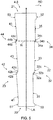
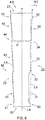
- Figures 5 and 6 disclose schematically a planar upper view of another blade segment 4, 8 applicable to be used in a stator 3 and/or a rotor 6 of a conical refiner, the refining surface 5, 9 of the blade segment 4, 8 being omitted in Figures 5 and 6 for the sake of clarity.
- the blade segment 4, 8 of Figures 5 and 6 is intended to extend as a single uniform piece from the inner end 18 of the stator 3/rotor 6 up to the outer end 19 of the stator 3/rotor 6.
- the following description is thus applicable to each blade segment 4, 4a, 4b, 8, 8a, 8b mentioned above, including the blade segments 4, 8 being formed by interconnecting the inner 4a, 8a and respective outer 4b, 8b blade segments.
- the blade segment 4, 4a, 4b, 8, 8a, 8b comprises an inner end edge 20 or a first end edge 20 to be directed towards the inner end 18 of the refining element 3, 6 having the smaller diameter.
- the blade segment further comprises an outer end edge 21 or a second end edge 21 to be directed towards the outer end 19 of the refining element 3, 6 having the larger diameter.
- the inner end edge of the blade segment provides an axially inner end of the blade segment and the outer end edge of the blade segment provides an axially outer end of the blade segment, the direction from the axially inner end towards the axially outer end thus providing the longitudinal axis of the blade segment.
- the outer end edge 21 is thus substantially opposite to the inner end edge 20 in the direction of the longitudinal axis of the blade segment.
- the longitudinal axis LA of the blade segment is shown schematically by arrows both at a centre line of the blade segments as well as at an edge line of the blade segments, which lines have a common intersecting point.
- Below the longitudinal axis LA at the edge line of the blade segment is also called edge axis and is denoted with the reference sign LA' and shown with broken lines in Figure 6 .
- Figures 4a, 4b and 5 the longitudinal axes of the blade segments are shown schematically at centre lines of the blade segments.
- a line denoting the longitudinal axis LA of the blade segment actually runs along the conical surface of the blade segment and therefore runs at an angle relative to the shaft 11 of the conical refiner 1 but may be projected at the shaft 11 so as to run parallel to the shaft 11 of the refiner 1.
- a line denoting the longitudinal axis LA of the blade segment running along the cylindrical surface of the blade segment runs substantially parallel to the shaft of the refiner.
- a line denoting the longitudinal axis LA of the blade segment runs along a substantially planar surface of the blade segment in a radial direction of the blade segment, i.e. in disc-like blade segments the longitudinal axis of the blade segment unites with the radial direction of the blade segment.
- the blade segment further comprises a first side edge 22 or a leading side edge 22 extending from the inner end edge 20 of the blade segment up to the outer end edge 21 of the blade segment and providing the side edge of the blade segment which first meets the edge of a counter blade segment during operation of the refiner, to be directed substantially towards the intended rotation direction RD of the rotor 6. So, in the rotor 6 it provides the side edge of the blade segment to be directed towards the intended rotation direction RD of the rotor 6 and in the stator 3 it provides the side edge of the blade segment to be directed to opposite direction relative to the intended rotation direction RD of the rotor 6.
- the blade segment further comprises a second side edge 23 or a trailing side edge 23 substantially opposite to the first side edge 22 in a direction substantially perpendicular to the longitudinal axis LA of the blade segment and extending from the inner end edge 20 of the blade segment up to the outer end edge 21 of the blade segment and providing the side edge of the blade segment which last meets the edge of a counter blade segment during operation of the refiner. So, in the rotor 6 it provides the side edge of the blade segment to be directed to the opposite direction relative to the intended rotation direction RD of the rotor 6 and in the stator 3 it provides the side edge to be directed towards the intended rotation direction RD of the rotor 6.
- the inner 20 and the outer 21 end edges together with the first 22 and second 23 side edges define a periphery of the blade segment 8.
- the blade segment comprises a body 24 having a front surface 25 to be directed towards the refining chamber 12 of the refiner 1.
- the front surface 25 of the blade segment body 24 is provided with blade bars 26 and blade grooves 27 which together provide the refining surface 5, 9 of the blade segment.
- the blade bars 26 are intended to defibre and refine the material to be refined and the blade grooves 27 are intended to convey the material to be refined forward along the refining surface 5, 9.
- Fastening holes 28 are intended to receive fastening means, like bolts, for fastening the blade segment to the supporting structures pf the stator and the hub of the rotor directly or via fastening elements, like rings, 29, 30 or the like.
- an extension or shoulder 50, 51, 52, 53 at least on one side edge 22, 23 of the segment.
- the extension or shoulder is intended to come into contact with a neighbouring blade segment when assembled to provide a part of a refining surface of a refining element of a refiner.
- Figure 4a and Figure 5 show the shoulders 50, 51 at the inner end of the blade segments 4, 4a, 8, 8a and Figure 4b and Figure 5 show the shoulders 52, 53 at the outer end of the blade segments 4, 4b, 8, 8b.
- the shoulders 50, 51, 52, 53 may lie on corners of one segment as in Figure 5 , or on corners of separate successive segments, i.e.
- edge axes LA' along the shoulder lines 50, 51, 52, 53, more specifically via the seam lines between the two neighbouring segments, and running parallel to the axial direction of the refiner (or the radial direction in case of a disc refiner) just like the longitudinal axis LA of the segment.
- the slit-like opening 14, 15 is formed on the first side edge 22 between the inner shoulder 50 and the outer shoulder 52, and on the second side edge 23 between the inner shoulder 51 and the outer shoulder 53.
- the slit-like longitudinal opening 14, 15 may run continuously from the innermost shoulder up to the outermost shoulder without interruptions other than those caused by ex-segment structures, like fastening rings.
- the slit-like longitudinal opening 14, 15 may be discontinuous between the innermost and outermost shoulders when the elbows are designed to have a contact with the neighbouring segment, as disclosed in more detail later.
- the first side edge 22 comprises, in a direction from the inner end edge 20 towards the outer end edge 21, at least a substantially straight first long edge portion 31.
- the direction of the first long edge portion 31 is arranged to deviate from the direction of the longitudinal axis LA of the blade segment, i.e. with respect to the direction of the longitudinal axis LA of the blade segment, such that the first long edge portion 31 is directed towards the centre part or the centre line of the blade segment, the centre line of the blade segment being denoted in Figures 4a, 4b and 5 by the longitudinal axis LA of the blade segment.
- the first long edge portion 31 is followed by a first bend 32a, which is turned away from the direction of the first long edge portion 31, i.e. to an opposite direction with respect to the direction of the longitudinal axis LA than the first long edge portion 31, that is away from the centre part or the centre line of the blade segment.
- the first bend 32a is followed by a substantially straight or slightly curved short edge portion 32b.
- the direction of the short edge portion 32b is arranged to deviate from the direction of the longitudinal axis LA to a different direction than the first long edge portion 31, i.e. to an opposite direction with respect to the direction of the longitudinal axis LA than the first long edge portion 31, that is away from the centre part or the centre line of the blade segment.
- the short edge portion 32b is followed by a second bend 32c which is turned away from the direction of the first short edge portion 32b, i.e. to an opposite direction with respect to the direction of the longitudinal axis LA than the short edge portion 32b, that is towards the centre part or the centre line of the blade segment.
- the first bend 32a, the short edge portion 32b and the second bend 32c provide an elbow 32 in the first side edge 22 of the blade segment.
- the second bend 32c or the elbow 32 is, in turn, followed by a substantially straight second long edge portion 33 the direction of which is arranged to deviate from the direction of the longitudinal axis LA of the blade segment to the same direction as the first long edge portion 31, i.e. towards the centre part or the centre line of the blade segment.
- the second long edge portion 33 is thus arranged to deviate with respect to the direction of the longitudinal axis LA to the same direction as the first long edge portion 31.
- the second side edge 23 of the blade segments 4, 4a, 4b, 8, 8a, 8b comprises, in a direction from the inner end edge 20 towards the outer end edge 21, at least a substantially straight first long edge portion 41.
- the direction of the first long edge portion 41 is arranged to deviate from the direction of the longitudinal axis LA of the blade segment, i.e. with respect to the direction of the longitudinal axis LA of the blade segment, such that the first long edge portion 41 is directed away from the centre part or the centre line of the blade segment.
- the first long edge portion 41 is followed by a first bend 42a, which is turned away from the direction of the first long edge portion 41, i.e. to an opposite direction with respect to the direction of the longitudinal axis LA than the first long edge portion 41, that is towards the centre part or the centre line of the blade segment.
- the first bend 42a is followed by a substantially straight or slightly curved short edge portion 42b.
- the direction of the short edge portion 42b is arranged to deviate from the direction of the longitudinal axis LA to a different direction than the first long edge portion 41, i.e. to an opposite direction with respect to the direction of the longitudinal axis LA than the first long edge portion 41, that is towards the centre line of the blade segment.
- the short edge portion 42b is followed by a second bend 42c which is turned away from the direction of the first short edge portion 42b, i.e. to an opposite direction with respect to the direction of the longitudinal axis LA than the short edge portion 42b, that is away from the centre line of the blade segment.
- the first bend 42a, the short edge portion 42b and the second bend 42c provide an elbow 42 in the second side edge 23 of the blade segment.
- the second bend 42c or the elbow 42 is, in turn, followed by a substantially straight second long edge portion 43 the direction of which is arranged to deviate from the direction of the longitudinal axis LA of the blade segment to the same direction as the first long edge portion 41, i.e. away from the centre part or the centre line of the blade segment.
- the second long edge portion 43 is thus arranged to deviate with respect to the direction of the longitudinal axis LA to the same direction as the first long edge portion 41.
- the first side edge 22 of the blade segment 4, 8 of Figure 5 further comprises another bevel 34 following the second long edge portion 33.
- the second long edge portion 33 is followed by a third bend 34a, which is turned away from the direction of the second long edge portion 33, i.e. to an opposite direction with respect to the direction of the longitudinal axis LA than the second long edge portion 33, that is away from the centre part or the centre line of the blade segment.
- the third bend 34a is followed by a second substantially straight or slightly curved short edge portion 34b.
- the direction of the second short edge portion 34b is arranged to deviate from the direction of the longitudinal axis LA to a different direction than the second long edge portion 33, i.e. to an opposite direction with respect to the direction of the longitudinal axis LA than the second long edge portion, that is away from the centre part or the centre line of the blade segment.
- the second short edge portion 34b is followed by a fourth bend 34c which is turned away from the direction of the second short edge portion 34b, i.e. to an opposite direction with respect to the direction of the longitudinal axis LA than the second short edge portion 34b, that is towards the centre part or the centre line of the blade segment.
- the third bend 34a, the second short edge portion 34b and the fourth bend 34c provide a second elbow 34 in the first side edge 22 of the blade segment.
- the fourth bend 34c or the second elbow 34 is, in turn, followed by a substantially straight third long edge portion 35 the direction of which is arranged to deviate from the direction of the longitudinal axis LA of the blade segment to the same direction as the first 31 and the second 33 long edge portions, i.e. towards the centre part or the centre line of the blade segment.
- the third long edge portion 35 is thus arranged to deviate with respect to the direction of the longitudinal axis LA to the same direction as the first 31 and the second 33 long edge portions.
- the second side edge 23 of the blade segment 4, 8 of Figure 5 comprises another bevel 44 following the second long edge portion 43.
- the second long edge portion 43 is followed by a third bend 44a, which is turned away from the direction of the second long edge portion 43, i.e. to an opposite direction with respect to the direction of the longitudinal axis LA than the second long edge portion, that is towards the centre part or the centre line of the blade segment.
- the third bend 44a is followed by a second substantially straight or slightly curved short edge portion 44b.
- the direction of the second short edge portion 44b is arranged to deviate from the direction of the longitudinal axis LA to a different direction than the second long edge portion 43, i.e. to an opposite direction with respect to the direction of the longitudinal axis LA than the second long edge portion, that is towards the centre part or the centre line of the blade segment.
- the second short edge portion 44b is followed by a fourth bend 44c which is turned away from the direction of the second short edge portion 44b, i.e. to an opposite direction with respect to the direction of the longitudinal axis LA than the second short edge portion 44b, that is away from the centre part or the centre line of the blade segment.
- the third bend 44a, the second short edge portion 44b and the fourth bend 44c provide a second elbow 44 in the second side edge 23 of the blade segment.
- the fourth bend 44c or the second elbow 44 is, in turn, followed by a substantially straight third long edge portion 45 the direction of which is arranged to deviate from the direction of the longitudinal axis LA of the blade segment to the same direction as the first 41 and the second 43 long edge portions, i.e. away from the centre part or the centre line of the blade segment.
- the third long edge portion 45 is thus arranged to deviate with respect to the direction of the longitudinal axis LA to the same direction as the first 41 and the second 43 long edge portions.
- both side edges 22, 23 of the blade segment comprise at least two edge portions 31, 33, 35, 41, 43, 45 arranged to deviate from the direction of the longitudinal axis LA of the blade segment 4, 4a, 4b, 8, 8a, 8b and being connected by an elbow 32, 34, 42, 44 between each two edge portions 31, 33, 35, 41, 43, 45.
- the configurations of the side edges 22, 23 are also arranged to deviate from a mirror image with respect to the longitudinal axis LA of the blade segment.
- At least one side edge 22, 23 of the blade segment 4, 4a, 4b, 8, 8a, 8b comprises at least two edge portions 31, 33, 35, 41, 43, 45 the directions of which are arranged to deviate from the direction of the longitudinal axis LA of the blade segment 4, 4a, 4b, 8, 8a, 8b, and the at least two edge portions are connected by an elbow 32, 34, 42, 44 between each two edge portions 31, 33, 35, 41, 43, 45.
- the directions of the edge portions at the specific side edge 22, 23 are arranged to deviate to the same direction from the direction of the longitudinal axis LA and the elbow 32, 34, 42, 44 is turned away from the edge portions 31, 33, 35, 41, 43, 45 such that it deviates with respect to the direction of the longitudinal axis LA of the blade segment to the different direction than the edge portions 31, 33, 35, 41, 43, 45.
- the reach of the elbows 32, 34 may be so arranged that it does not substantially exceed the edge axis LA', whereby a continuous slit-like opening 14, 15 between the neighbouring segments 4, 8 may be provided.
- the reach of the elbows 42, 44 may be so arranged that the elbow extends up to the edge axis LA', like the elbow 44, or exceeds the edge axis LA', like the elbow 42. If the opposite side edges 22, 23 are not parallel the elbow may exceed the edge axis LA' even to such an extent that it enables contact with a neighbouring segment, whereby a discontinuous slit-like opening 14, 15 between the neighbouring segments 4, 8 may be provided.
- the disclosed configuration of the side edge of the blade segment provides a shape of gentle zigzag that deviates from the direction of the longitudinal axis of the blade segment.
- the configuration of the opposite side edge When the configuration of the opposite side edge is selected in co-operation with the configuration of the first mentioned side edge, it provides longitudinal slit-like openings, i.e. flow paths, between the neighbouring blade segments for supplying the fibrous material to be refined into the refining chamber between the stator and the rotor and for discharging the fibrous material already refined out of the refining chamber.
- This slit-like opening has therefore a centre line the direction of which deviates from the direction of the axis of the blade segment at least at most part of the extension of the opening.
- the slit-like opening has a width between 10 mm and 25 mm.
- the edge portions at the same side edge 22, 23 of the blade segment and arranged to deviate to the same direction from the direction of the longitudinal axis LA of the blade segment are substantially parallel.
- the effect of this is that an opening of substantially constant width is easy to implement between neighbouring blade segments.
- each side edge of the blade segment comprises at least one elbow.
- both side edges of the blade segment has a kind of shape of gentle zigzag, preventing thereby a significant portion of the side edge from following the longitudinal axis of the blade segment and thereby preventing a formation of opening portions possibly causing a tendency of vibration of the refiner during the operation thereof.
- the elbows at the opposite side edges lie on the same normal level with respect to the longitudinal axis LA of the blade segment, the normal of the longitudinal axis LA of the blade segment being schematically shown in Figure 5 with a broken line denoted with the reference sign N.
- This has the effect of providing an opening with a substantially constant width along the longitudinal extension of the opening.
- a number of elbows at each side edge 22, 23 is from one to ten, preferably from two to six, or from two to seven, or from two to eight.
- the deviation of the direction of extension of the opening from the longitudinal axis of the blade segment may be ensured. Too dense zigzag shape of the side edge of the blade segment may result in a perpetual back-and-forth type flow path for the pulp which eventually does not differ so much from the vibrationally possibly undesired design.
- an angle of the deviation of the elbow from the longitudinal axis LA of the blade segment is about 10 - 90 degrees, preferably from 10 to 60 degrees, and more preferably from 10 to 50 degrees.
- a direction of an extension of the elbow is substantially parallel to a direction of an extension of a blade bar.
- the elbow is arranged to form an angle which is substantially parallel to the blade bar angle applied in the blade segment.
- configurations of the side edges 22, 23 are arranged to deviate from a mirror image with respect to a longitudinal axis of the blade segment, or in other words, the side edges of the blade segment are not mirror images of each other with respect to the longitudinal axis LA of the blade segment.
Landscapes
- Paper (AREA)
Abstract
Description
- The invention relates to refiners for refining fibrous material and especially to a blade segment for a refiner for refining fibrous material.
- Refiners used for refining fibrous material, such as refiners used for manufacturing mechanical pulp or in any low consistency refining, comprise typically two refining elements opposite to each other and turning relative to each other, i.e. one or both of them is/are rotating. The refining elements comprise refining surfaces provided with blade bars and blade grooves therebetween, the blade bars being intended to defiber and refine the material to be refined and the blade grooves being intended to convey the material to be refined forward along the refining surfaces. The refining surface of the refining element is typically formed of several blade segments fastened to a body of the respective refining element, each blade segment comprising a respective refining surface formed by blade bars and blade grooves therebetween. The complete refining surface of the refining element is thus formed of the refining surfaces of several blade segments fastened next to each other in the refining element.
EP-publication 3401439 B1 discloses a blade segment applicable to be used in refiners for refining fibrous material. - An object of the present invention is to provide a novel blade segment for a refiner for refining fibrous material, as well as a novel refiner for refining fibrous material.
- The invention is characterized by the features of the independent claim.
- The invention is based on the idea of configuring at least one side edge of the blade segment to provide such a shape that deviates from a direction of a longitudinal axis of the blade segment.
- When the shape of at least one side edge of the blade segment is arranged to have a shape that deviates from the direction of the longitudinal axis of the blade segment, and when the configuration of the opposite side edge is selected in co-operation with the configuration of the first mentioned side edge, it provides longitudinal slit-like openings providing flow paths between the neighbouring blade segments for supplying the fibrous material to be refined into the refining chamber between the stator and the rotor and for discharging the fibrous material already refined out of the refining chamber. This slit-like opening has therefore a centre line the direction of which deviates from the direction of the longitudinal axis of the blade segment at least at most part of the extension of the opening. This has the effect that an angle of incidence between the openings in the rotor and in the stator changes in the axial direction of the refiner, causing a point of incidence between the openings in the rotor and in the stator to move from the axial direction of the refiner. This, in turn, has the effect that possible flow variations appearing in an operation of a refiner of prior art may be diminished.
- Some embodiments of the invention are disclosed in the dependent claims.
- In the following the invention will be described in greater detail by means of preferred embodiments with reference to the accompanying drawings, in which
-
Figure 1 is a schematic general side view of a conical refiner in cross-section; -
Figure 2 is a schematic oblique side view of a stator and a rotor applicable to be used in the refiner ofFigure 1 ; -
Figure 3 is a schematic planar upper view of a set of stator/rotor blade segments; -
Figures 4a and 4b are schematic planar upper views of blade segments according to the solution; and -
Figures 5 and6 show a schematic planar upper view of another blade segment according to the solution. - For the sake of clarity, the figures show some embodiments of the invention in a simplified manner. Like reference numerals identify like elements in the figures.
-
Figure 1 is a schematic general side view of a general construction of a refiner 1 in cross-section, which refiner may be used for refining a fibrous material, such as a wood material containing lignocellulose or another fibre material suitable to be used for manufacturing paper or paperboard, for example. The refiner 1 shown inFigure 1 is of conical type but disc-refiners, conical-disc-refiners and cylindrical refiners could be used as well as an example here. Generally, a refiner comprises at least two substantially oppositely positioned refining elements at least one of which is rotating, and a refining chamber formed between each two substantially oppositely positioned refining elements. In the following a refiner with only one rotatable refining element is described. - The refiner 1 of
Figure 1 comprises a frame 2 and a stationary,fixed refining element 3, i.e. astator 3, supported on the frame 2. Thestator 3 comprises two or more stator blade segments 4, each of them comprising blade bars and blade grooves therebetween. The blade bars and the blade grooves in each stator blade segment 4 form arefining surface 5 of the respective blade segment 4, therefining surface 5 of each stator blade segment 4 thereby providing a part of a refining surface of thestator 3. A complete refining surface of thestator 3 is formed of therefining surfaces 5 of a necessary number of the blade segments 4 fastened next to each other in thestator 3 so that thecomplete refining surface 5 extending over the whole circumference of thestator 3 is provided. For the sake of clarity, both the refining surface of each single stator blade segment 4 as well as the complete refining surface of thestator 3 are herein denoted with thesame reference sign 5. - The refiner 1 further comprises a
rotatable refining element 6, i.e. arotor 6, of the refiner 1. Therotor 6 comprises ahub 7. Therotor 6 further comprises two or morerotor blade segments 8 supported to thehub 7, eachrotor blade segment 8 comprising blade bars and blade grooves therebetween. The blade bars and the blade grooves in eachrotor blade segment 8 form arefining surface 9 of therespective blade segment 8, therefining surface 9 of eachrotor blade segment 8 thereby providing a part of a refining surface of therotor 6. A complete refining surface of therotor 6 is formed of therefining surfaces 9 of a necessary number of theblade segments 8 fastened next to each other in therotor 6 so that thecomplete refining surface 9 extending over the whole circumference of therotor 6 is provided. For the sake of clarity, both the refining surface of each singlerotor blade segment 8 as well as the complete refining surface of therotor 6 are herein denoted with thesame reference sign 9. - The
hub 7 of therotor 6 is connected to adriving motor 10 by ashaft 11 so that therotor 6 can be rotated relative to thestator 3 in a direction of arrow RD, for instance, the arrow RD thus indicating an intended rotation direction RD of therotor 6. - The refiner 1 may also comprise a loading device which, for the sake of clarity, is not shown in
Figure 1 . The loading device can be used for moving back and forth therotor 6 attached to theshaft 11, as schematically shown by arrow A, in order to adjust a size of arefining gap 12, i.e. arefining chamber 12, between thestator 3 and therotor 6, wherein the fibrous material is actually refined. - The fibrous material to be refined is fed into the refiner 1 via a
feed channel 13 in a manner shown by arrow F. In one embodiment most of the fibrous material fed into the refiner 1 passes, in a manner schematically shown by arrows P, throughopenings 14, i.e. flow paths, in the refiningsurface 9 of therotor 6 into therefining chamber 12, wherein the fibrous material is to be refined. Furthermore, most of the already refined fibrous material is, in turn, discharged throughopenings 15, i.e. flow paths, in therefining surface 9 of thestator 3 into anintermediate space 16 between the frame 2 of the refiner 1 and thestator 3, wherefrom the refined material is removed via adischarge channel 17 from the refiner 1, as schematically shown by arrow D. - Since the space between the
rotor 6 and the frame 2 of the refiner 1 ofFigure 1 is not fully closed, some of the fibrous material to be fed into the refiner 1 may transfer into therefining chamber 12 from the right end of therefining chamber 12, i.e. from afirst end 18 or aninner end 18 of the refiner 1 having a smaller diameter, as seen inFigure 1 . Correspondingly, some of the already refined material may also exit therefining chamber 12 from the left end of therefining chamber 12, i.e. from asecond end 19 or anouter end 19 of the refiner 1 having a larger diameter, as seen inFigure 1 , wherefrom a connection is provided to theintermediate space 16. - In the embodiment of
Figure 1 of the refiner 1, only onefeed channel 13 is provided, and it is arranged at thefirst end 18 of the refiner 1 having the smaller diameter. The actual implementation of the refiner could also comprise a second feed channel arranged at thesecond end 19 of the refiner 1 having the larger diameter, whereby thedischarge channel 17 of the refiner 1 could be arranged for example somewhere between the first 18 and second 19 ends of the refiner 1. In the following, thereference sign 18 and the termfirst end 18 or the terminner end 18 may indicate both thefirst end 18 or theinner end 18 of the refiner 1 having the smaller diameter and thefirst end 18 or theinner end 18 of therefining element refining chamber 12 having the smaller diameter. Correspondingly, thereference sign 19 and the termsecond end 19 or the termouter end 19 may indicate both thesecond end 19 or theouter end 19 of the refiner 1 having the larger diameter and thesecond end 19 or theouter end 19 of therefining element refining chamber 12 having the larger diameter. - It is emphasized that in addition to the conical refiner disclosed above the blade segment of the solution described herein may be applied in other kind of conical refiners too. In addition to the conical refiners the blade segment of the solution described herein is applicable also in cylindrical refiners and disc refiners as well as in refiners comprising both a conical portion and a disc portion.
-
Figure 2 is a schematic oblique side view of astator 3 and arotor 6 of a conical refiner, thestator 3 being shown in cross-section. In the circumferential direction of thestator 3 there are a number of adjacentinner blade segments 4a on the side of theinner end 18 of thestator 3 and a respective number of adjacentouter blade segments 4b on the side of theouter end 19 of thestator 3, which inner 4a and outer 4b segments together provide a blade segment 4. Eachinner blade segment 4a is interconnected with the respectiveouter blade segment 4b at the corresponding circumferential position of thestator 3, providing a blade segment 4 that provides a substantiallycontinuous refining surface 5 between theinner end 18 and theouter end 19 of thestator 3 at the respective inner 4a and outer 4b stator blade segments of this blade segment 4. Side edges of thestator blade segments like openings 15 making flow paths are provided between the interconnected stator blade segments 4 in the circumferential direction of thestator 3. - Similarly, in the circumferential direction of the
rotor 6 there are a number of adjacentinner blade segments 8a on the side of theinner end 18 of therotor 6 and a respective number of adjacentouter blade segments 8b on the side of theouter end 19 of therotor 6, which inner 8a and outer 8b blade segments together provide ablade segment 8. Eachinner blade segment 8a is interconnected with the respectiveouter blade segment 8b at the corresponding circumferential position of therotor 6, providing ablade segment 8 that provides a substantiallycontinuous refining surface 9 between theinner end 18 and theouter end 19 of therotor 6 at the respective inner 8a and outer 8b stator blade segments of thisblade segment 8. Side edges of therotor blade segments like openings 14 making flow paths are provided between the interconnectedrotor blade segments 8 in the circumferential direction of therotor 6.Figure 3 is a schematic planar upper view of a set of adjacent interconnectedstator blade segments rotor blade segments refining surface stator 3 or arotor 6 substantially similar to that ofFigure 2 . - When the
rotor blade segments hub 7 of therotor 6, there will thus be longitudinal slit-like openings 14 between the neighbouringrotor blade segments 8 in the circumferential direction of therotor 6, through whichopenings 14 the fibre material to the refined is supplied into therefining chamber 12 between therotor 6 and thestator 3. Similarly, there will be longitudinal slit-like openings 15 between the neighbouring stator blade segments 4 in the circumferential direction of thestator 3, through whichopenings 15 the fibre material already refined in therefining chamber 12 is discharged out of therefining chamber 12. The configuration of this kind of refiner is called a side feed configuration or a side feed refiner. - In the following the blade segment structure according to the solution disclosed herein is considered in more detail in view of
Figures 4a, 4b ,5 and6 , whereinFigure 4a shows schematically a planar upper view of ablade segment inner end 18 of thestator 3 or therotor 6 andFigure 4b shows schematically a planar upper view of ablade segment outer end 19 of thestator 3 or therotor 6.Figures 5 and6 , in turn, disclose schematically a planar upper view of anotherblade segment 4, 8 applicable to be used in astator 3 and/or arotor 6 of a conical refiner, therefining surface blade segment 4, 8 being omitted inFigures 5 and6 for the sake of clarity. When consideringFigure 2 above, theblade segment 4, 8 ofFigures 5 and6 is intended to extend as a single uniform piece from theinner end 18 of thestator 3/rotor 6 up to theouter end 19 of thestator 3/rotor 6.The following description is thus applicable to eachblade segment blade segments 4, 8 being formed by interconnecting the inner 4a, 8a and respective outer 4b, 8b blade segments. - The
blade segment inner end edge 20 or afirst end edge 20 to be directed towards theinner end 18 of therefining element outer end edge 21 or asecond end edge 21 to be directed towards theouter end 19 of therefining element outer end edge 21 is thus substantially opposite to theinner end edge 20 in the direction of the longitudinal axis of the blade segment. InFigure 3 the longitudinal axis LA of the blade segment is shown schematically by arrows both at a centre line of the blade segments as well as at an edge line of the blade segments, which lines have a common intersecting point. Below the longitudinal axis LA at the edge line of the blade segment is also called edge axis and is denoted with the reference sign LA' and shown with broken lines inFigure 6 . InFigures 4a, 4b and5 the longitudinal axes of the blade segments are shown schematically at centre lines of the blade segments. - It is to be noted that in the blade segment intended to a conical refiner, a line denoting the longitudinal axis LA of the blade segment actually runs along the conical surface of the blade segment and therefore runs at an angle relative to the
shaft 11 of the conical refiner 1 but may be projected at theshaft 11 so as to run parallel to theshaft 11 of the refiner 1. In a blade segment intended to a cylindrical refiner, in turn, a line denoting the longitudinal axis LA of the blade segment running along the cylindrical surface of the blade segment runs substantially parallel to the shaft of the refiner. Furthermore, in a blade segment intended to a disc refiner, in turn, a line denoting the longitudinal axis LA of the blade segment runs along a substantially planar surface of the blade segment in a radial direction of the blade segment, i.e. in disc-like blade segments the longitudinal axis of the blade segment unites with the radial direction of the blade segment. - The blade segment further comprises a
first side edge 22 or a leadingside edge 22 extending from theinner end edge 20 of the blade segment up to theouter end edge 21 of the blade segment and providing the side edge of the blade segment which first meets the edge of a counter blade segment during operation of the refiner, to be directed substantially towards the intended rotation direction RD of therotor 6. So, in therotor 6 it provides the side edge of the blade segment to be directed towards the intended rotation direction RD of therotor 6 and in thestator 3 it provides the side edge of the blade segment to be directed to opposite direction relative to the intended rotation direction RD of therotor 6. - The blade segment further comprises a
second side edge 23 or a trailingside edge 23 substantially opposite to thefirst side edge 22 in a direction substantially perpendicular to the longitudinal axis LA of the blade segment and extending from theinner end edge 20 of the blade segment up to theouter end edge 21 of the blade segment and providing the side edge of the blade segment which last meets the edge of a counter blade segment during operation of the refiner. So, in therotor 6 it provides the side edge of the blade segment to be directed to the opposite direction relative to the intended rotation direction RD of therotor 6 and in thestator 3 it provides the side edge to be directed towards the intended rotation direction RD of therotor 6. The inner 20 and the outer 21 end edges together with the first 22 and second 23 side edges define a periphery of theblade segment 8. - The blade segment comprises a
body 24 having afront surface 25 to be directed towards therefining chamber 12 of the refiner 1. Thefront surface 25 of theblade segment body 24 is provided withblade bars 26 andblade grooves 27 which together provide therefining surface blade grooves 27 are intended to convey the material to be refined forward along therefining surface - At the innermost and outermost end edges of the segment there is an extension or
shoulder side edge Figure 4a andFigure 5 show theshoulders blade segments Figure 4b andFigure 5 show theshoulders blade segments shoulders Figure 5 , or on corners of separate successive segments, i.e. on corner(s) of theinner segment outer segment Figures 4a and 4b . Naturally, all the corners of thesegment 4, 8 could be provided with ashoulder Figures 4a, 4b theinner segment shoulders inner edge 20 or alternatively on each corner thereof, and respectively, theouter segment shoulders outer edge 21 or alternatively on each corner thereof. The amount of shoulders per side edge of one segment is from 2 to 10. Basically, theseshoulders - In
Figure 6 there are also drawn edge axes LA' along the shoulder lines 50, 51, 52, 53, more specifically via the seam lines between the two neighbouring segments, and running parallel to the axial direction of the refiner (or the radial direction in case of a disc refiner) just like the longitudinal axis LA of the segment. The slit-like opening first side edge 22 between theinner shoulder 50 and theouter shoulder 52, and on thesecond side edge 23 between theinner shoulder 51 and theouter shoulder 53. The slit-likelongitudinal opening longitudinal opening - Referring to
Figures 4a, 4b and5 and theblade segments 4, 8 therein, thefirst side edge 22 comprises, in a direction from theinner end edge 20 towards theouter end edge 21, at least a substantially straight firstlong edge portion 31. The direction of the firstlong edge portion 31 is arranged to deviate from the direction of the longitudinal axis LA of the blade segment, i.e. with respect to the direction of the longitudinal axis LA of the blade segment, such that the firstlong edge portion 31 is directed towards the centre part or the centre line of the blade segment, the centre line of the blade segment being denoted inFigures 4a, 4b and5 by the longitudinal axis LA of the blade segment. - The first
long edge portion 31 is followed by afirst bend 32a, which is turned away from the direction of the firstlong edge portion 31, i.e. to an opposite direction with respect to the direction of the longitudinal axis LA than the firstlong edge portion 31, that is away from the centre part or the centre line of the blade segment. - The
first bend 32a is followed by a substantially straight or slightly curvedshort edge portion 32b. The direction of theshort edge portion 32b is arranged to deviate from the direction of the longitudinal axis LA to a different direction than the firstlong edge portion 31, i.e. to an opposite direction with respect to the direction of the longitudinal axis LA than the firstlong edge portion 31, that is away from the centre part or the centre line of the blade segment. - The
short edge portion 32b is followed by asecond bend 32c which is turned away from the direction of the firstshort edge portion 32b, i.e. to an opposite direction with respect to the direction of the longitudinal axis LA than theshort edge portion 32b, that is towards the centre part or the centre line of the blade segment. - The
first bend 32a, theshort edge portion 32b and thesecond bend 32c provide anelbow 32 in thefirst side edge 22 of the blade segment. - The
second bend 32c or theelbow 32 is, in turn, followed by a substantially straight secondlong edge portion 33 the direction of which is arranged to deviate from the direction of the longitudinal axis LA of the blade segment to the same direction as the firstlong edge portion 31, i.e. towards the centre part or the centre line of the blade segment. The secondlong edge portion 33 is thus arranged to deviate with respect to the direction of the longitudinal axis LA to the same direction as the firstlong edge portion 31. - Furthermore, the
second side edge 23 of theblade segments inner end edge 20 towards theouter end edge 21, at least a substantially straight firstlong edge portion 41. The direction of the firstlong edge portion 41 is arranged to deviate from the direction of the longitudinal axis LA of the blade segment, i.e. with respect to the direction of the longitudinal axis LA of the blade segment, such that the firstlong edge portion 41 is directed away from the centre part or the centre line of the blade segment. - The first
long edge portion 41 is followed by afirst bend 42a, which is turned away from the direction of the firstlong edge portion 41, i.e. to an opposite direction with respect to the direction of the longitudinal axis LA than the firstlong edge portion 41, that is towards the centre part or the centre line of the blade segment. - The
first bend 42a is followed by a substantially straight or slightly curvedshort edge portion 42b. The direction of theshort edge portion 42b is arranged to deviate from the direction of the longitudinal axis LA to a different direction than the firstlong edge portion 41, i.e. to an opposite direction with respect to the direction of the longitudinal axis LA than the firstlong edge portion 41, that is towards the centre line of the blade segment. - The
short edge portion 42b is followed by asecond bend 42c which is turned away from the direction of the firstshort edge portion 42b, i.e. to an opposite direction with respect to the direction of the longitudinal axis LA than theshort edge portion 42b, that is away from the centre line of the blade segment. - The
first bend 42a, theshort edge portion 42b and thesecond bend 42c provide anelbow 42 in thesecond side edge 23 of the blade segment. - The
second bend 42c or theelbow 42 is, in turn, followed by a substantially straight secondlong edge portion 43 the direction of which is arranged to deviate from the direction of the longitudinal axis LA of the blade segment to the same direction as the firstlong edge portion 41, i.e. away from the centre part or the centre line of the blade segment. The secondlong edge portion 43 is thus arranged to deviate with respect to the direction of the longitudinal axis LA to the same direction as the firstlong edge portion 41. - When further considering the
blade segment 4, 8 ofFigure 5 , thefirst side edge 22 of theblade segment 4, 8 ofFigure 5 further comprises anotherbevel 34 following the secondlong edge portion 33. Thereby the secondlong edge portion 33 is followed by athird bend 34a, which is turned away from the direction of the secondlong edge portion 33, i.e. to an opposite direction with respect to the direction of the longitudinal axis LA than the secondlong edge portion 33, that is away from the centre part or the centre line of the blade segment. - The
third bend 34a is followed by a second substantially straight or slightly curvedshort edge portion 34b. The direction of the secondshort edge portion 34b is arranged to deviate from the direction of the longitudinal axis LA to a different direction than the secondlong edge portion 33, i.e. to an opposite direction with respect to the direction of the longitudinal axis LA than the second long edge portion, that is away from the centre part or the centre line of the blade segment. - The second
short edge portion 34b is followed by afourth bend 34c which is turned away from the direction of the secondshort edge portion 34b, i.e. to an opposite direction with respect to the direction of the longitudinal axis LA than the secondshort edge portion 34b, that is towards the centre part or the centre line of the blade segment. - The
third bend 34a, the secondshort edge portion 34b and thefourth bend 34c provide asecond elbow 34 in thefirst side edge 22 of the blade segment. - The
fourth bend 34c or thesecond elbow 34 is, in turn, followed by a substantially straight thirdlong edge portion 35 the direction of which is arranged to deviate from the direction of the longitudinal axis LA of the blade segment to the same direction as the first 31 and the second 33 long edge portions, i.e. towards the centre part or the centre line of the blade segment. The thirdlong edge portion 35 is thus arranged to deviate with respect to the direction of the longitudinal axis LA to the same direction as the first 31 and the second 33 long edge portions. - Similarly, the
second side edge 23 of theblade segment 4, 8 ofFigure 5 comprises anotherbevel 44 following the secondlong edge portion 43. Thereby the secondlong edge portion 43 is followed by athird bend 44a, which is turned away from the direction of the secondlong edge portion 43, i.e. to an opposite direction with respect to the direction of the longitudinal axis LA than the second long edge portion, that is towards the centre part or the centre line of the blade segment. - The
third bend 44a is followed by a second substantially straight or slightly curvedshort edge portion 44b. The direction of the secondshort edge portion 44b is arranged to deviate from the direction of the longitudinal axis LA to a different direction than the secondlong edge portion 43, i.e. to an opposite direction with respect to the direction of the longitudinal axis LA than the second long edge portion, that is towards the centre part or the centre line of the blade segment. - The second
short edge portion 44b is followed by afourth bend 44c which is turned away from the direction of the secondshort edge portion 44b, i.e. to an opposite direction with respect to the direction of the longitudinal axis LA than the secondshort edge portion 44b, that is away from the centre part or the centre line of the blade segment. - The
third bend 44a, the secondshort edge portion 44b and thefourth bend 44c provide asecond elbow 44 in thesecond side edge 23 of the blade segment. - The
fourth bend 44c or thesecond elbow 44 is, in turn, followed by a substantially straight thirdlong edge portion 45 the direction of which is arranged to deviate from the direction of the longitudinal axis LA of the blade segment to the same direction as the first 41 and the second 43 long edge portions, i.e. away from the centre part or the centre line of the blade segment. The thirdlong edge portion 45 is thus arranged to deviate with respect to the direction of the longitudinal axis LA to the same direction as the first 41 and the second 43 long edge portions. - In the embodiments of the blade segments of
Figures 4a, 4b and5 , both side edges 22, 23 of the blade segment comprise at least twoedge portions blade segment elbow edge portions - In the embodiments of the blade segments of
Figures 4a, 4b and5 , the configurations of the side edges 22, 23 are also arranged to deviate from a mirror image with respect to the longitudinal axis LA of the blade segment. - Generally, according to the disclosed solution, at least one
side edge blade segment edge portions blade segment elbow edge portions - According to a further embodiment, the directions of the edge portions at the
specific side edge elbow edge portions edge portions - According to an embodiment of the blade segment, as schematically shown on the side of the
first side edge 22 of theblade segment 4, 8 inFigure 6 , the reach of theelbows short edge portion like opening segments 4, 8 may be provided. - According to an embodiment of the blade segment, as schematically shown on the side of the
second side edge 23 of theblade segment 4, 8 inFigure 6 , the reach of theelbows elbow 44, or exceeds the edge axis LA', like theelbow 42. If the opposite side edges 22, 23 are not parallel the elbow may exceed the edge axis LA' even to such an extent that it enables contact with a neighbouring segment, whereby a discontinuous slit-like opening segments 4, 8 may be provided. - The disclosed configuration of the side edge of the blade segment provides a shape of gentle zigzag that deviates from the direction of the longitudinal axis of the blade segment. When the configuration of the opposite side edge is selected in co-operation with the configuration of the first mentioned side edge, it provides longitudinal slit-like openings, i.e. flow paths, between the neighbouring blade segments for supplying the fibrous material to be refined into the refining chamber between the stator and the rotor and for discharging the fibrous material already refined out of the refining chamber. This slit-like opening has therefore a centre line the direction of which deviates from the direction of the axis of the blade segment at least at most part of the extension of the opening. This has the effect that an angle of incidence between the openings in the rotor and in the stator changes in the axial direction of the refiner, or the longitudinal axis and the edge axis of the blade segments, causing a point of incidence between the openings in the rotor and in the stator to move from the axial direction of the refiner or the longitudinal axis of the blade segments. This, in turn, has the effect that possible flow pulse variations and thus vibrations appearing during the operation of a refiner may be diminished.
- According to an embodiment the slit-like opening has a width between 10 mm and 25 mm.
- According to an embodiment, the edge portions at the
same side edge - According to an embodiment, each side edge of the blade segment comprises at least one elbow. The effect of this is that both side edges of the blade segment has a kind of shape of gentle zigzag, preventing thereby a significant portion of the side edge from following the longitudinal axis of the blade segment and thereby preventing a formation of opening portions possibly causing a tendency of vibration of the refiner during the operation thereof.
- According to an embodiment, the elbows at the opposite side edges lie on the same normal level with respect to the longitudinal axis LA of the blade segment, the normal of the longitudinal axis LA of the blade segment being schematically shown in
Figure 5 with a broken line denoted with the reference sign N. This has the effect of providing an opening with a substantially constant width along the longitudinal extension of the opening. - According to an embodiment, a number of elbows at each
side edge - According to an embodiment, an angle of the deviation of the elbow from the longitudinal axis LA of the blade segment is about 10 - 90 degrees, preferably from 10 to 60 degrees, and more preferably from 10 to 50 degrees.
- According to an embodiment, a direction of an extension of the elbow is substantially parallel to a direction of an extension of a blade bar. In other words, the elbow is arranged to form an angle which is substantially parallel to the blade bar angle applied in the blade segment.
- According to an embodiment, configurations of the side edges 22, 23 are arranged to deviate from a mirror image with respect to a longitudinal axis of the blade segment, or in other words, the side edges of the blade segment are not mirror images of each other with respect to the longitudinal axis LA of the blade segment.
- It will be obvious to a person skilled in the art that, as the technology advances, the inventive concept can be implemented in various ways. The invention and its embodiments are not limited to the examples described above but may vary within the scope of the claims.
Claims (16)
- A blade segment (4, 8) for a refiner (1) for refining fibrous material, the blade segment (4, 8) comprising
a first end edge (20) and a second end edge (21) opposite to the first end edge in a direction of a longitudinal axis (LA) of the blade segment (4, 4a, 4b, 8, 8a, 8b),
a first side edge (22) and a second side edge (23) opposite to the first side edge (22), the first side edge (22) and the second side edge (23) extending between the first end edge (20) and the second end edge (21),
a refining surface (5, 9) comprising blade bars (26) and blade grooves (27) therebetween on a front surface (25) of the blade segment (4, 8), and wherein
characterized in that
at least one side edge (22, 23) comprises at least two edge portions (31, 33, 35, 41, 43, 45) arranged to deviate from the direction of the longitudinal axis (LA) of the blade segment (4, 4a, 4b, 8, 8a, 8b) and being connected by an elbow (32, 34, 42, 44) between each two edge portions (31, 33, 35, 41, 43, 45). - A blade segment as claimed in claim 1, characterized in that the edge portions (31, 33, 35, 41, 43, 45) are arranged to deviate to the same direction with respect to the direction of the longitudinal axis (LA) and the elbow (32, 34, 42, 44) is turned away from the edge portions (31, 33, 35, 41, 43, 45) to deviate with respect to the direction of the longitudinal axis (LA) to different direction than the edge portions (31, 33, 35, 41, 43, 45).
- A blade segment as claimed in claim 1 or 2, characterized in that both side edges (22, 23) comprise at least two edge portions (31, 33, 35, 41, 43, 45) arranged to deviate from the direction of the longitudinal axis (LA) of the blade segment (4, 4a, 4b, 8, 8a, 8b) and being connected by the elbow (32, 34, 42, 44) between each two edge portions (31, 33, 35, 41, 43, 45).
- A blade segment as claimed in any one of the preceding claims, characterized in that the edge portions (31, 33, 35,41, 43, 45) being at the same side edge (22, 23) and arranged to deviate to the same direction from the direction of the longitudinal axis (LA) are substantially parallel.
- A blade segment as claimed in any one of the preceding claims, characterized in that the side edge (22, 23) comprises, in a direction from the inner end edge (20) towards the outer end edge (21), at least a substantially straight first long edge portion (31, 41) arranged to deviate from the direction of the longitudinal axis (LA) of the blade segment (4, 4a, 4b, 8, 8a, 8b), a first bend (32a, 42a) following the first long edge portion (31, 41) and turned away from the direction of the first long edge portion (31, 41), a substantially straight short edge portion (32b, 42b) following the first bend (32a, 42a) and arranged to deviate from the direction of the longitudinal axis (LA) of the blade segment (4, 4a, 4b, 8, 8a, 8b) to a different direction than the first long edge portion (31, 41), a second bend (32c, 42c) following the first short edge portion (32b, 42b) and turned away from the direction of the first short edge portion (32b, 42b) and a substantially straight second long edge portion (33, 43) following the second bend (32c, 42c) and arranged to deviate from the direction of the longitudinal axis (LA) of the blade segment (4, 4a, 4b, 8, 8a, 8b) to the same direction as the first long edge portion (31, 41), wherein the first bend (32a, 42a), the short edge portion (32b, 42b) and the second bend (32c, 42c) provide the elbow (32, 42) in the side edge (22, 23) of the blade segment (4, 4a, 4b, 8, 8a, 8b).
- A blade segment as claimed in any one of the preceding claims, characterized in that each side edge (22, 23) comprises at least one elbow (32, 34, 42, 44).
- A blade segment as claimed in any one of the preceding claims, characterized in that elbows (32, 34, 42, 44) at the opposite side edges (22, 23) lie on the same normal (N) level with respect to the longitudinal axis (LA).
- A blade segment as claimed in any one of the preceding claims, characterized in that a number of elbows (32, 34, 42, 44) at each side edge (22, 23) is from one to ten, preferably from two to about seven.
- A blade segment as claimed in any one of the preceding claims, characterized in that an angle of the deviation of the elbow (32, 34,42,44) with respect to the longitudinal axis (LA) is about 10 - 90 degrees.
- A blade segment as claimed in any one of the preceding claims, characterized in that a direction of an extension of the elbow (32, 34, 42, 44) is substantially parallel to a direction of an extension of the blade bar (26).
- A blade segment as claimed in any one of the preceding claims, characterized in that configurations of the side edges (22, 23) are arranged to deviate from a mirror image with respect to a longitudinal axis (LA) of the blade segment (4, 4a, 4b, 8, 8a, 8b).
- A blade segment as claimed in any one of the preceding claims, characterized in that the elbow (42) is arranged to exceed an edge axis (LA') of the blade segment (4, 4a, 4b, 8, 8a, 8b).
- A blade segment as claimed in any one of the preceding claims, characterized in that there are at least at one end of the blade segment (4, 4a, 4b, 8, 8a, 8b) at both corners of the blade segment (4, 4a, 4b, 8, 8a, 8b) a shoulder (50, 51, 52, 53) which comes into contact with a neighbouring blade segment (4, 4a, 4b, 8, 8a, 8b) when assembled to provide a part of a refining surface (5, 9) of a refining element (3, 6) of a refiner (1).
- A refiner for refining fibrous material, characterized in that the refiner (1) comprises at least one blade segment (4, 4a, 4b, 8, 8a, 8b) as claimed in any one of claims 1 to 13.
- A refiner for refining fibrous material, characterized in that in a refining element (3, 6) of the refiner (1) there is a continuous slit-like opening (14, 15) between neighbouring blade segments (4, 4a, 4b, 8, 8a, 8b).
- A refiner for refining fibrous material, characterized in that in a refining element (3, 6) of the refiner (1) there is a discontinuous slit-like opening (14, 15) between neighbouring blade segments (4, 4a, 4b, 8, 8a, 8b).
Priority Applications (8)
| Application Number | Priority Date | Filing Date | Title |
|---|---|---|---|
| EP20178487.3A EP3919675B1 (en) | 2020-06-05 | 2020-06-05 | Blade segment for a refiner |
| BR112022023725A BR112022023725A2 (en) | 2020-06-05 | 2021-06-02 | BLADE SEGMENT FOR A REFINER, AND REFINER FOR REFINING FIBROUS MATERIAL |
| CA3179136A CA3179136A1 (en) | 2020-06-05 | 2021-06-02 | Blade segment for refiner |
| KR1020227041230A KR20230020403A (en) | 2020-06-05 | 2021-06-02 | Blade segments for refiners |
| CN202180040543.4A CN115698423B (en) | 2020-06-05 | 2021-06-02 | Blade segment for a refiner |
| PCT/EP2021/064841 WO2021245161A1 (en) | 2020-06-05 | 2021-06-02 | Blade segment for refiner |
| US18/007,679 US12410558B2 (en) | 2020-06-05 | 2021-06-02 | Blade segment for refiner |
| JP2022574530A JP7697173B2 (en) | 2020-06-05 | 2021-06-02 | Blade segments for refiners |
Applications Claiming Priority (1)
| Application Number | Priority Date | Filing Date | Title |
|---|---|---|---|
| EP20178487.3A EP3919675B1 (en) | 2020-06-05 | 2020-06-05 | Blade segment for a refiner |
Publications (2)
| Publication Number | Publication Date |
|---|---|
| EP3919675A1 true EP3919675A1 (en) | 2021-12-08 |
| EP3919675B1 EP3919675B1 (en) | 2026-04-15 |
Family
ID=71016408
Family Applications (1)
| Application Number | Title | Priority Date | Filing Date |
|---|---|---|---|
| EP20178487.3A Active EP3919675B1 (en) | 2020-06-05 | 2020-06-05 | Blade segment for a refiner |
Country Status (8)
| Country | Link |
|---|---|
| US (1) | US12410558B2 (en) |
| EP (1) | EP3919675B1 (en) |
| JP (1) | JP7697173B2 (en) |
| KR (1) | KR20230020403A (en) |
| CN (1) | CN115698423B (en) |
| BR (1) | BR112022023725A2 (en) |
| CA (1) | CA3179136A1 (en) |
| WO (1) | WO2021245161A1 (en) |
Citations (1)
| Publication number | Priority date | Publication date | Assignee | Title |
|---|---|---|---|---|
| EP3401439B1 (en) | 2017-05-11 | 2019-10-09 | Valmet Technologies Oy | Blade segment for a refiner |
Family Cites Families (7)
| Publication number | Priority date | Publication date | Assignee | Title |
|---|---|---|---|---|
| US56433A (en) * | 1866-07-17 | Improvement in quartz-mills | ||
| US1329742A (en) * | 1918-11-05 | 1920-02-03 | Nat Equip Co | Reducing apparatus |
| FI124677B (en) * | 2008-06-19 | 2014-11-28 | Valmet Technologies Inc | Grinder, refiner surface, steel segment and method for milling fibrous material |
| FI125031B (en) * | 2011-01-27 | 2015-04-30 | Valmet Technologies Inc | Refiner and leaf elements |
| DE102014009588A1 (en) * | 2014-06-27 | 2016-01-14 | Andritz Fiedler Gmbh | Set for mechanical working, in particular grinding of suspended pulp material |
| FI126263B (en) * | 2014-10-29 | 2016-09-15 | Valmet Technologies Inc | Blade element for refiner and refiner for refining fiber material |
| WO2020163459A1 (en) * | 2019-02-06 | 2020-08-13 | Andritz Inc. | Refiner plate segments having feeding grooves |
-
2020
- 2020-06-05 EP EP20178487.3A patent/EP3919675B1/en active Active
-
2021
- 2021-06-02 US US18/007,679 patent/US12410558B2/en active Active
- 2021-06-02 JP JP2022574530A patent/JP7697173B2/en active Active
- 2021-06-02 CA CA3179136A patent/CA3179136A1/en active Pending
- 2021-06-02 WO PCT/EP2021/064841 patent/WO2021245161A1/en not_active Ceased
- 2021-06-02 KR KR1020227041230A patent/KR20230020403A/en active Pending
- 2021-06-02 CN CN202180040543.4A patent/CN115698423B/en active Active
- 2021-06-02 BR BR112022023725A patent/BR112022023725A2/en unknown
Patent Citations (1)
| Publication number | Priority date | Publication date | Assignee | Title |
|---|---|---|---|---|
| EP3401439B1 (en) | 2017-05-11 | 2019-10-09 | Valmet Technologies Oy | Blade segment for a refiner |
Also Published As
| Publication number | Publication date |
|---|---|
| CA3179136A1 (en) | 2021-12-09 |
| KR20230020403A (en) | 2023-02-10 |
| JP2023527922A (en) | 2023-06-30 |
| US20230228033A1 (en) | 2023-07-20 |
| US12410558B2 (en) | 2025-09-09 |
| EP3919675B1 (en) | 2026-04-15 |
| CN115698423B (en) | 2025-01-10 |
| CN115698423A (en) | 2023-02-03 |
| WO2021245161A1 (en) | 2021-12-09 |
| JP7697173B2 (en) | 2025-06-24 |
| BR112022023725A2 (en) | 2022-12-20 |
Similar Documents
| Publication | Publication Date | Title |
|---|---|---|
| EP3401439B1 (en) | Blade segment for a refiner | |
| EP2198082B1 (en) | Refiner | |
| EP2664709A1 (en) | Blade element for a conical portion of a stator | |
| EP3786357B1 (en) | Blade element pair for a refiner | |
| JP7754391B2 (en) | Blade elements for refiners | |
| EP3919675B1 (en) | Blade segment for a refiner | |
| AU721789B2 (en) | Feeding element for fibrous material | |
| FI126708B (en) | Grinder and blade element for refiner | |
| EP4165244B1 (en) | Blade segment for a refiner | |
| EP4162108B1 (en) | Blade segment for a refiner | |
| EP4083316A1 (en) | Blade element | |
| CN119175760B (en) | Blades for a fine grinding mill for refining lignocellulosic materials and a fine grinding mill including at least one blade. | |
| US20220333303A1 (en) | Flow-altering refiner segment | |
| JP2024536206A (en) | Refining segments for refiners | |
| CN119175760A (en) | Blade of refiner for refining lignocellulosic material and refiner comprising at least one blade |
Legal Events
| Date | Code | Title | Description |
|---|---|---|---|
| PUAI | Public reference made under article 153(3) epc to a published international application that has entered the european phase |
Free format text: ORIGINAL CODE: 0009012 |
|
| STAA | Information on the status of an ep patent application or granted ep patent |
Free format text: STATUS: THE APPLICATION HAS BEEN PUBLISHED |
|
| AK | Designated contracting states |
Kind code of ref document: A1 Designated state(s): AL AT BE BG CH CY CZ DE DK EE ES FI FR GB GR HR HU IE IS IT LI LT LU LV MC MK MT NL NO PL PT RO RS SE SI SK SM TR |
|
| B565 | Issuance of search results under rule 164(2) epc |
Effective date: 20201119 |
|
| STAA | Information on the status of an ep patent application or granted ep patent |
Free format text: STATUS: REQUEST FOR EXAMINATION WAS MADE |
|
| 17P | Request for examination filed |
Effective date: 20220603 |
|
| RBV | Designated contracting states (corrected) |
Designated state(s): AL AT BE BG CH CY CZ DE DK EE ES FI FR GB GR HR HU IE IS IT LI LT LU LV MC MK MT NL NO PL PT RO RS SE SI SK SM TR |
|
| P01 | Opt-out of the competence of the unified patent court (upc) registered |
Effective date: 20230602 |
|
| GRAP | Despatch of communication of intention to grant a patent |
Free format text: ORIGINAL CODE: EPIDOSNIGR1 |
|
| STAA | Information on the status of an ep patent application or granted ep patent |
Free format text: STATUS: GRANT OF PATENT IS INTENDED |
|
| INTG | Intention to grant announced |
Effective date: 20251110 |
|
| GRAS | Grant fee paid |
Free format text: ORIGINAL CODE: EPIDOSNIGR3 |
|
| GRAA | (expected) grant |
Free format text: ORIGINAL CODE: 0009210 |
|
| STAA | Information on the status of an ep patent application or granted ep patent |
Free format text: STATUS: THE PATENT HAS BEEN GRANTED |
|
| AK | Designated contracting states |
Kind code of ref document: B1 Designated state(s): AL AT BE BG CH CY CZ DE DK EE ES FI FR GB GR HR HU IE IS IT LI LT LU LV MC MK MT NL NO PL PT RO RS SE SI SK SM TR |
|
| REG | Reference to a national code |
Ref country code: CH Ref legal event code: F10 Free format text: ST27 STATUS EVENT CODE: U-0-0-F10-F00 (AS PROVIDED BY THE NATIONAL OFFICE) Effective date: 20260415 |
|
| REG | Reference to a national code |
Ref country code: DE Ref legal event code: R096 Ref document number: 602020070312 Country of ref document: DE |