EP3919398A1 - Double-layered container - Google Patents
Double-layered container Download PDFInfo
- Publication number
- EP3919398A1 EP3919398A1 EP19913451.1A EP19913451A EP3919398A1 EP 3919398 A1 EP3919398 A1 EP 3919398A1 EP 19913451 A EP19913451 A EP 19913451A EP 3919398 A1 EP3919398 A1 EP 3919398A1
- Authority
- EP
- European Patent Office
- Prior art keywords
- layer body
- shoulder
- outside air
- mouth portion
- outer layer
- Prior art date
- Legal status (The legal status is an assumption and is not a legal conclusion. Google has not performed a legal analysis and makes no representation as to the accuracy of the status listed.)
- Granted
Links
Images



Classifications
-
- B—PERFORMING OPERATIONS; TRANSPORTING
- B65—CONVEYING; PACKING; STORING; HANDLING THIN OR FILAMENTARY MATERIAL
- B65D—CONTAINERS FOR STORAGE OR TRANSPORT OF ARTICLES OR MATERIALS, e.g. BAGS, BARRELS, BOTTLES, BOXES, CANS, CARTONS, CRATES, DRUMS, JARS, TANKS, HOPPERS, FORWARDING CONTAINERS; ACCESSORIES, CLOSURES, OR FITTINGS THEREFOR; PACKAGING ELEMENTS; PACKAGES
- B65D1/00—Rigid or semi-rigid containers having bodies formed in one piece, e.g. by casting metallic material, by moulding plastics, by blowing vitreous material, by throwing ceramic material, by moulding pulped fibrous material or by deep-drawing operations performed on sheet material
- B65D1/02—Bottles or similar containers with necks or like restricted apertures, designed for pouring contents
- B65D1/0207—Bottles or similar containers with necks or like restricted apertures, designed for pouring contents characterised by material, e.g. composition, physical features
- B65D1/0215—Bottles or similar containers with necks or like restricted apertures, designed for pouring contents characterised by material, e.g. composition, physical features multilayered
-
- B—PERFORMING OPERATIONS; TRANSPORTING
- B65—CONVEYING; PACKING; STORING; HANDLING THIN OR FILAMENTARY MATERIAL
- B65D—CONTAINERS FOR STORAGE OR TRANSPORT OF ARTICLES OR MATERIALS, e.g. BAGS, BARRELS, BOTTLES, BOXES, CANS, CARTONS, CRATES, DRUMS, JARS, TANKS, HOPPERS, FORWARDING CONTAINERS; ACCESSORIES, CLOSURES, OR FITTINGS THEREFOR; PACKAGING ELEMENTS; PACKAGES
- B65D1/00—Rigid or semi-rigid containers having bodies formed in one piece, e.g. by casting metallic material, by moulding plastics, by blowing vitreous material, by throwing ceramic material, by moulding pulped fibrous material or by deep-drawing operations performed on sheet material
- B65D1/02—Bottles or similar containers with necks or like restricted apertures, designed for pouring contents
- B65D1/0223—Bottles or similar containers with necks or like restricted apertures, designed for pouring contents characterised by shape
- B65D1/023—Neck construction
- B65D1/0246—Closure retaining means, e.g. beads, screw-threads
-
- B—PERFORMING OPERATIONS; TRANSPORTING
- B65—CONVEYING; PACKING; STORING; HANDLING THIN OR FILAMENTARY MATERIAL
- B65D—CONTAINERS FOR STORAGE OR TRANSPORT OF ARTICLES OR MATERIALS, e.g. BAGS, BARRELS, BOTTLES, BOXES, CANS, CARTONS, CRATES, DRUMS, JARS, TANKS, HOPPERS, FORWARDING CONTAINERS; ACCESSORIES, CLOSURES, OR FITTINGS THEREFOR; PACKAGING ELEMENTS; PACKAGES
- B65D1/00—Rigid or semi-rigid containers having bodies formed in one piece, e.g. by casting metallic material, by moulding plastics, by blowing vitreous material, by throwing ceramic material, by moulding pulped fibrous material or by deep-drawing operations performed on sheet material
- B65D1/02—Bottles or similar containers with necks or like restricted apertures, designed for pouring contents
- B65D1/0223—Bottles or similar containers with necks or like restricted apertures, designed for pouring contents characterised by shape
- B65D1/0261—Bottom construction
- B65D1/0276—Bottom construction having a continuous contact surface, e.g. Champagne-type bottom
-
- B—PERFORMING OPERATIONS; TRANSPORTING
- B65—CONVEYING; PACKING; STORING; HANDLING THIN OR FILAMENTARY MATERIAL
- B65D—CONTAINERS FOR STORAGE OR TRANSPORT OF ARTICLES OR MATERIALS, e.g. BAGS, BARRELS, BOTTLES, BOXES, CANS, CARTONS, CRATES, DRUMS, JARS, TANKS, HOPPERS, FORWARDING CONTAINERS; ACCESSORIES, CLOSURES, OR FITTINGS THEREFOR; PACKAGING ELEMENTS; PACKAGES
- B65D23/00—Details of bottles or jars not otherwise provided for
- B65D23/02—Linings or internal coatings
-
- B—PERFORMING OPERATIONS; TRANSPORTING
- B65—CONVEYING; PACKING; STORING; HANDLING THIN OR FILAMENTARY MATERIAL
- B65D—CONTAINERS FOR STORAGE OR TRANSPORT OF ARTICLES OR MATERIALS, e.g. BAGS, BARRELS, BOTTLES, BOXES, CANS, CARTONS, CRATES, DRUMS, JARS, TANKS, HOPPERS, FORWARDING CONTAINERS; ACCESSORIES, CLOSURES, OR FITTINGS THEREFOR; PACKAGING ELEMENTS; PACKAGES
- B65D79/00—Kinds or details of packages, not otherwise provided for
- B65D79/005—Packages having deformable parts for indicating or neutralizing internal pressure-variations by other means than venting
- B65D79/008—Packages having deformable parts for indicating or neutralizing internal pressure-variations by other means than venting the deformable part being located in a rigid or semi-rigid container, e.g. in bottles or jars
- B65D79/0084—Packages having deformable parts for indicating or neutralizing internal pressure-variations by other means than venting the deformable part being located in a rigid or semi-rigid container, e.g. in bottles or jars in the sidewall or shoulder part thereof
-
- B—PERFORMING OPERATIONS; TRANSPORTING
- B65—CONVEYING; PACKING; STORING; HANDLING THIN OR FILAMENTARY MATERIAL
- B65D—CONTAINERS FOR STORAGE OR TRANSPORT OF ARTICLES OR MATERIALS, e.g. BAGS, BARRELS, BOTTLES, BOXES, CANS, CARTONS, CRATES, DRUMS, JARS, TANKS, HOPPERS, FORWARDING CONTAINERS; ACCESSORIES, CLOSURES, OR FITTINGS THEREFOR; PACKAGING ELEMENTS; PACKAGES
- B65D2501/00—Containers having bodies formed in one piece
- B65D2501/0009—Bottles or similar containers with necks or like restricted apertures designed for pouring contents
- B65D2501/0018—Ribs
- B65D2501/0027—Hollow longitudinal ribs
Definitions
- the present disclosure relates to a double container.
- Double containers are conventionally known as containers for containing foods such as food seasonings, e.g. soy sauce, and beverages, cosmetics such as skin lotions, and toiletries such as shampoos, hair conditioners, and liquid soaps as contents.
- Such a double container has a double structure in which an inner layer body capable of volume-reduction deformation is located on the inner side of an outer layer body forming the outer shell of the container.
- the double container can form, for example, a squeeze-type discharge container combined with a discharge cap having a check valve, or a pump-type container combined with a pump.
- the contents contained in the inner layer body can be discharged to the outside by squeezing (pressing) the barrel portion of the outer layer body or operating the pump. Meanwhile, by introducing outside air between the inner layer body and the outer layer body from an outside air introduction port provided at a predetermined position, the outer shell shape of the container can be maintained while the inner layer body remains volume-reduction deformed.
- the contents can be discharged without replacing the contents with outside air inside the inner layer body, so that the contents contained in the inner layer body can be prevented from being in contact with outside air and thus prevented from degradation or degeneration.
- the double container can be formed by biaxial stretch blow molding a preform having a double structure in which an inner body is located on the inner side of an outer body (for example, see JP 2017-178434 A (PTL 1)).
- an inner layer body is mainly made of a polyester resin and an air passage from an outside air introduction port provided in a mouth portion to a barrel portion is secured easily.
- a double container is a double container that has an outer layer body and an inner layer body located on an inner side of the outer layer body and mainly made of a polyester resin and is formed by biaxial stretch blow molding, the double container comprising: a tubular mouth portion; a shoulder portion connected to a lower end of the mouth portion, gradually increasing in diameter in a downward direction, and having an outward protruding curved shape over a length in a vertical direction in a longitudinal section; a barrel portion connected to a lower end of the shoulder portion; and a bottom portion closing a lower end of the barrel portion, wherein the mouth portion has an outside air introduction port for introducing outside air between the outer layer body and the inner layer body, and the double container comprises a shoulder rib that is concave or convex as seen from outside and at least extends from an upper end of the shoulder portion to the lower end of the shoulder portion.
- a plurality of the shoulder rib may be radially arranged in a top view.
- an inner layer body is mainly made of a polyester resin and an air passage from an outside air introduction port provided in a mouth portion to a barrel portion is secured easily.
- a double container 1 (hereafter also referred to as "container 1") according to this embodiment has an outer layer body 2 and an inner layer body 3 located on the inner side of the outer layer body 2, and is formed by biaxial stretch blow molding.
- the container 1 includes an approximately cylindrical mouth portion 4 having a central axis O, a shoulder portion 5 connected to the lower end of the mouth portion 4, a barrel portion 6 connected to the lower end of the shoulder portion 5, and a bottom portion 7 closing the lower end of the barrel portion 6.
- vertical direction (up-down direction) denotes a direction along the central axis O
- upward denotes a direction from the bottom portion 7 to the mouth portion 4 (for example, upward in FIG. 1 )
- the term “downward” denotes a direction opposite to the upward direction.
- the term “longitudinal section” denotes a section by a plane including the central axis O
- the term “cross section” denotes a section by a plane perpendicular to the central axis O.
- the mouth portion 4 has a male screw 4a for screwing the peripheral wall of a discharge cap.
- the mouth portion 4 may have a protrusion of an annular shape or the like that can be undercut-engaged with the peripheral wall of the discharge cap by capping.
- the mouth portion 4 has an outside air introduction port 13 for introducing outside air between the outer layer body 3 and the inner layer body 2. The detailed structure of the outside air introduction port 13 will be described later.
- An annular seal protrusion 4b centered at the central axis O is provided in a part of the mouth portion 4 lower than the outside air introduction port 13.
- the seal protrusion 4b may be in close contact with the peripheral wall of the discharge cap, air between the outer layer body 3 and the inner layer body 2 can be prevented from leaking from the lower end of the peripheral wall of the discharge cap through the outside air introduction port 13 when the barrel portion 6 is squeezed (pressed).
- the seal protrusion 4b may be omitted.
- An annular neck ring 4c centered at the central axis O is provided in a part of the mouth portion 4 lower than the seal protrusion 4b. The shape of the neck ring 4c may be changed as appropriate. The neck ring 4c may be omitted.
- the shoulder portion 5 gradually increases in diameter in the downward direction, and has a curved shape protruding to the outside of the container 1 over a length in the vertical direction in a longitudinal section.
- the shoulder portion 5 has an approximately circular shape in a cross section.
- the barrel portion 6 has an approximately cylindrical shape centered at the central axis O.
- the barrel portion 6 has four groove-shaped annular ribs 6a extending in the circumferential direction.
- the shape of the barrel portion 6 may be changed as appropriate.
- the barrel portion 6 may not include the annular ribs 6a.
- the bottom portion 7 has an annular grounding portion 7a centered at the central axis O and a bottom panel 7b located on the inner side of the grounding portion 7a.
- the shape of the bottom portion 7 may be changed as appropriate.
- the outer layer body 2 is mainly made of polyethylene terephthalate (PET).
- PET polyethylene terephthalate
- the outer layer body 2 forms the outer shell of the container 1, and the part of the outer layer body 2 forming the barrel portion 6 has flexibility of being deformable by squeezing operation and resilience of being restorable by an elastic force after deformation.
- the outer layer body 2 may not have such flexibility and resilience.
- the main material of the outer layer body 2 is not limited to PET.
- the main material of the outer layer body 2 may be a polyester resin other than PET, such as polytrimethylene terephthalate (PTT), polybutylene terephthalate (PBT), or polyethylene naphthalate (PEN), or a polyolefin resin such as polypropylene (PP) or polyethylene (PE).
- PET polytrimethylene terephthalate
- PBT polybutylene terephthalate
- PEN polyethylene naphthalate
- a polyolefin resin such as polypropylene (PP) or polyethylene (PE).
- the main material of the outer layer body 2 is preferably a polyester resin.
- the outer layer body 2 is not limited to a single layer structure, and may have a multi-layer structure that can improve the barrier property and the like.
- the inner layer body 3 is mainly made of PET.
- the main material of the inner layer body 3 is not limited to PET.
- the main material of the inner layer body 3 may be a polyester resin other than PET, such as polytrimethylene terephthalate (PTT), polybutylene terephthalate (PBT), or polyethylene naphthalate (PEN).
- the inner layer body 3 has a bag shape thinner than the outer layer body 2.
- a containing space S connected to an upper end opening 4d of the mouth portion 4 is formed inside the inner layer body 3.
- the containing space S is capable of containing any of foods such as food seasonings, e.g. soy sauce, and beverages, cosmetics such as skin lotions, and toiletries such as shampoos, hair conditioners, and liquid soaps as contents.
- the contents are not limited to foods, cosmetics, or toiletries.
- the inner layer body 3 is not limited to a single layer structure, and may have a multi-layer structure that can improve the barrier property, the content resistance, and the like
- the main material of each of the outer layer body 2 and the inner layer body 3 is biaxially stretchable PET.
- An example of such biaxially stretchable PET is homo-PET.
- other types of PET such as IPA (isophthalic acid) modified PET and CHDM modified PET may be used.
- the PET forming the outer layer body 2 and the PET forming the inner layer body 3 may be different.
- the container 1 is formed by biaxial stretch blow molding a preform 9 illustrated in FIG. 4 .
- the preform 9 has an outer body 10 that forms the outer layer body 2 and an inner body 11 that forms the inner layer body 3.
- the preform 9 has a double preform structure composed of the outer body 10 and the inner body 11.
- the preform 9 includes a mouth portion 4 having substantially the same structure as the mouth portion 4 in the container 1 as it is not substantially stretched in the biaxial stretch blow molding.
- a bottomed cylindrical (test tube shape) preform barrel portion 12 is connected below the mouth portion 4.
- the outer body 10 has a cylindrical outer mouth portion 10a that forms the mouth portion 4.
- a male screw 4a, a seal protrusion 4b, and a neck ring 4c are provided on the outer peripheral surface of the outer mouth portion 10a.
- the outer mouth portion 10a has an outside air introduction port 13 that is a horizontally long through hole, in the part between the male screw 4a and the seal protrusion 4b.
- the outer mouth portion 10a has two outside air introduction ports 13 with the central axis O being located therebetween.
- the number of outside air introduction ports 13 and the arrangement and shape of the outside air introduction ports 13 may be changed as appropriate.
- the male screw 4a has a notch 14 directly above the outside air introduction port 13. An outside air inlet provided in the discharge cap and the outside air introduction port 13 communicate via the notch 14. Alternatively, the male screw 4a may not have the notch 14.
- An outer barrel portion 10b that forms the preform barrel portion 12 is connected below the outer mouth portion 10a.
- the outer barrel portion 10b has an upper part that gradually decreases in outer diameter and gradually increases in thickness in the downward direction, a cylindrical middle part that has an approximately uniform thickness in the vertical direction, and a semispherical lower part that closes the lower end of the middle part.
- the shape of the outer barrel portion 10b may be changed as appropriate.
- the inner body 11 includes a stepped cylindrical inner mouth portion 11a that forms the mouth portion 4.
- the inner mouth portion 11a has an annular flange 15 placed on the upper end of the outer mouth portion 10a, a cylindrical upper tube 16 vertically suspended from the inner peripheral edge of the flange 15 and in contact with the inner surface of the outer mouth portion 10a, a conical inclined tube 17 that decreases in diameter in the downward direction from the lower end of the upper tube 16, and part of a cylindrical lower tube 18 (i.e. part except a lower part) vertically suspended from the lower end of the inclined tube 17.
- the upper end of the inclined tube 17 is located higher than the upper end of the pair of outside air introduction ports 13.
- the inner barrel portion 11b that forms the preform barrel portion 12 is connected below the inner mouth portion 11a.
- the inner barrel portion 11b has an upper part composed of the lower part of the lower tube 18 and an inclined portion 19 that gradually decreases in outer diameter and gradually increases in thickness in the downward direction from the lower part, a cylindrical middle part that has an approximately uniform thickness in the vertical direction, and a semispherical lower part that closes the lower end of the middle part.
- the shape of the inner barrel portion 11b may be changed as appropriate according to the shape of the outer barrel portion 10b.
- the inner body 11 has projection pieces 20 extending in the vertical direction from the upper end of the inclined tube 17 to the upper part of the inclined portion 19.
- Three projection pieces 20 are arranged on each of the two sides of an axis passing through both of the pair of outside air introduction ports 13 in a top view so that, even after biaxial stretch blow molding, a space for air passage can be favorably maintained between the outer layer body 2 and the inner layer body 3 around and below the outside air introduction ports 13.
- the number of projection pieces 20 and the arrangement and shape of the projection pieces 20 may be changed as appropriate.
- the projection pieces 20 may be omitted.
- the preform 9 can be molded into the container 1 by biaxial stretch blow molding that involves stretching in the axial direction by a stretching rod and stretching in the circumferential direction by blowing pressurized air (or liquid as contents).
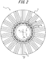
- the container 1 formed in this way has, in the shoulder portion 5, a plurality of (18 in this embodiment) shoulder ribs 8 formed along the shape of the cavity of the mold for blow molding. In FIGS. 1 and 2 , only one of the plurality of shoulder rib 8 is given the reference sign.
- the shoulder ribs 8 are arranged radially around the central axis O in a top view. That is, each shoulder rib 8 extends in the radial direction of the central axis O in a top view.
- the shoulder ribs 8 are spaced at regular intervals in the circumferential direction of the central axis O.
- the number of shoulder ribs 8 and the arrangement of the shoulder ribs 8 in the circumferential direction of the central axis O may be changed as appropriate.
- Each shoulder rib 8 is concave as seen from outside the container 1, and extends from the upper end to the lower end of the shoulder portion 5.
- each shoulder rib 8 has an upper end 8a located at the upper end of the shoulder portion 5 and a lower end 8b located at the lower end of the shoulder portion 5.
- the expression “the upper end 8a of the rib 8 is located at the upper end of the shoulder portion 5" includes not only the case where the upper end 8a of the rib 8 and the upper end of the shoulder portion 5 match but also the case where the upper end 8a of the rib 8 deviates from the upper end of the shoulder portion 5 upward or downward by at most such an extent that is approximately equal to the thickness of the outer layer body 2.
- the lower end 8b of the rib 8 is located at the lower end of the shoulder portion 5" includes not only the case where the lower end 8b of the rib 8 and the lower end of the shoulder portion 5 match but also the case where the lower end 8b of the rib 8 deviates from the lower end of the shoulder portion 5 upward or downward by at most such an extent that is approximately equal to the thickness of the outer layer body 2.
- Each shoulder rib 8 at least extends from the upper end to the lower end of the shoulder portion 5.
- Each shoulder rib 8 has a U cross sectional shape that gradually decreases in width inward in the radial direction of the central axis O, substantially throughout its length.
- the structure in which the shoulder portion 5 has an outward protruding curved shape over a length in the vertical direction as in this embodiment combined with the use of a polyester resin having a higher tensile elastic modulus (Young's modulus) than a polyolefin resin or the like as the main material of the inner layer body 3, makes it difficult for the inner layer body 3 to deform inward in the shoulder portion 5, so that it is difficult to secure the air passage in the shoulder portion 5.
- a plurality of shoulder ribs 8 that at least extend from the upper end to the lower end of the shoulder portion 5 and are arranged radially in a top view are provided.
- the plurality of shoulder ribs 8 make it possible to stably secure the air passage between the outer layer body 2 and the inner layer body 3 in the shoulder portion 5, so that outside air can be smoothly introduced into the barrel portion 6 after the contents are discharged.
- the mouth portion 4, the shoulder portion 5, and the barrel portion 6 in the container 1 have a circular tubular shape in a cross section in the foregoing embodiment, the present disclosure is not limited to such.
- the mouth portion 4, the shoulder portion 5, and the barrel portion 6 may have a polygonal or elliptical tubular shape in a cross section.
- each outside air introduction port 13 is a through hole passing through the part (the outer mouth portion 10a) forming the mouth portion 4 in the outer layer body 2 in the foregoing embodiment, the present disclosure is not limited to such.
- the outside air introduction port 13 may be provided between the part (the outer mouth portion 10a) forming the mouth portion 4 in the outer layer body 2 and the part (the inner mouth portion 11a) forming the mouth portion 4 in the inner layer body 3.
- the outside air introduction port 13 may be a groove continuous from the outer peripheral edge of the flange 15 of the inner mouth portion 11a to the lower end of the upper tube 16 on the lower surface of the flange 15 and the outer peripheral surface of the upper tube 16, and/or a groove continuous from the outer peripheral edge of the upper end surface of the outer mouth portion 10a to a position beyond the lower end of the upper tube 16 on the upper end surface of the outer mouth portion 10a and the inner peripheral surface of the outer mouth portion 10a.
- the plurality of shoulder ribs 8 are concave as seen from outside the container 1 in the foregoing embodiment, the present disclosure is not limited to such.
- the plurality of shoulder ribs 8 may be convex as seen from outside the container 1.
- the plurality of shoulder ribs 8 are arranged radially in a top view in the foregoing embodiment, the present disclosure is not limited to such.
- the plurality of shoulder ribs 8 may each extend in a direction inclined with respect to the radial direction of the central axis O in a top view, or have a curved or bent shape in a top view.
- the number of shoulder ribs 8 is not limited to two or more, and may be one.
Landscapes
- Engineering & Computer Science (AREA)
- Mechanical Engineering (AREA)
- Ceramic Engineering (AREA)
- Containers Having Bodies Formed In One Piece (AREA)
Abstract
Description
- The present disclosure relates to a double container.
- Double containers are conventionally known as containers for containing foods such as food seasonings, e.g. soy sauce, and beverages, cosmetics such as skin lotions, and toiletries such as shampoos, hair conditioners, and liquid soaps as contents.
- Such a double container has a double structure in which an inner layer body capable of volume-reduction deformation is located on the inner side of an outer layer body forming the outer shell of the container. The double container can form, for example, a squeeze-type discharge container combined with a discharge cap having a check valve, or a pump-type container combined with a pump. In this case, the contents contained in the inner layer body can be discharged to the outside by squeezing (pressing) the barrel portion of the outer layer body or operating the pump. Meanwhile, by introducing outside air between the inner layer body and the outer layer body from an outside air introduction port provided at a predetermined position, the outer shell shape of the container can be maintained while the inner layer body remains volume-reduction deformed. With such a double container, the contents can be discharged without replacing the contents with outside air inside the inner layer body, so that the contents contained in the inner layer body can be prevented from being in contact with outside air and thus prevented from degradation or degeneration.
- The double container can be formed by biaxial stretch blow molding a preform having a double structure in which an inner body is located on the inner side of an outer body (for example, see
JP 2017-178434 A - PTL 1:
JP 2017-178434 A - In the conventional double container described in PTL 1, in the case where the outside air introduction port is provided in the mouth portion, there is a possibility that the air passage from the outside air introduction port to the barrel portion is not secured, and outside air cannot be smoothly introduced into the barrel portion after the contents are discharged. Securing the air passage is particularly difficult in the case where the inner layer body is mainly made of a polyester resin such as polyethylene terephthalate.
- It could therefore be helpful to provide a double container in which an inner layer body is mainly made of a polyester resin and an air passage from an outside air introduction port provided in a mouth portion to a barrel portion is secured easily.
- A double container according to an aspect of the present disclosure is a double container that has an outer layer body and an inner layer body located on an inner side of the outer layer body and mainly made of a polyester resin and is formed by biaxial stretch blow molding, the double container comprising: a tubular mouth portion; a shoulder portion connected to a lower end of the mouth portion, gradually increasing in diameter in a downward direction, and having an outward protruding curved shape over a length in a vertical direction in a longitudinal section; a barrel portion connected to a lower end of the shoulder portion; and a bottom portion closing a lower end of the barrel portion, wherein the mouth portion has an outside air introduction port for introducing outside air between the outer layer body and the inner layer body, and the double container comprises a shoulder rib that is concave or convex as seen from outside and at least extends from an upper end of the shoulder portion to the lower end of the shoulder portion.
- In the double container according to an aspect of the present disclosure, a plurality of the shoulder rib may be radially arranged in a top view.
- It is thus possible to provide a double container in which an inner layer body is mainly made of a polyester resin and an air passage from an outside air introduction port provided in a mouth portion to a barrel portion is secured easily.
- In the accompanying drawings:
-
FIG. 1 is a partial sectional side view of a double container according to one of the disclosed embodiments; -
FIG. 2 is a top view of the double container illustrated inFIG. 1 ; -
FIG. 3 is a sectional view along A-A inFIG. 2 ; and -
FIG. 4 is a partial sectional side view of a preform before being molded into the double container illustrated inFIG. 1 . - A double container according to one of the disclosed embodiments will be described in detail below, with reference to the drawings.
- As illustrated in
FIG. 1 , a double container 1 (hereafter also referred to as "container 1") according to this embodiment has an outer layer body 2 and an inner layer body 3 located on the inner side of the outer layer body 2, and is formed by biaxial stretch blow molding. - As illustrated in
FIGS. 1 and2 , the container 1 includes an approximatelycylindrical mouth portion 4 having a central axis O, ashoulder portion 5 connected to the lower end of themouth portion 4, abarrel portion 6 connected to the lower end of theshoulder portion 5, and a bottom portion 7 closing the lower end of thebarrel portion 6. Herein, the term "vertical direction" (up-down direction) denotes a direction along the central axis O, the term "upward" denotes a direction from the bottom portion 7 to the mouth portion 4 (for example, upward inFIG. 1 ), and the term "downward" denotes a direction opposite to the upward direction. The term "longitudinal section" denotes a section by a plane including the central axis O, and the term "cross section" denotes a section by a plane perpendicular to the central axis O. - The
mouth portion 4 has amale screw 4a for screwing the peripheral wall of a discharge cap. Instead of themale screw 4a, themouth portion 4 may have a protrusion of an annular shape or the like that can be undercut-engaged with the peripheral wall of the discharge cap by capping. Themouth portion 4 has an outsideair introduction port 13 for introducing outside air between the outer layer body 3 and the inner layer body 2. The detailed structure of the outsideair introduction port 13 will be described later. Anannular seal protrusion 4b centered at the central axis O is provided in a part of themouth portion 4 lower than the outsideair introduction port 13. As a result of theseal protrusion 4b being in close contact with the peripheral wall of the discharge cap, air between the outer layer body 3 and the inner layer body 2 can be prevented from leaking from the lower end of the peripheral wall of the discharge cap through the outsideair introduction port 13 when thebarrel portion 6 is squeezed (pressed). Alternatively, theseal protrusion 4b may be omitted. Anannular neck ring 4c centered at the central axis O is provided in a part of themouth portion 4 lower than theseal protrusion 4b. The shape of theneck ring 4c may be changed as appropriate. Theneck ring 4c may be omitted. - The
shoulder portion 5 gradually increases in diameter in the downward direction, and has a curved shape protruding to the outside of the container 1 over a length in the vertical direction in a longitudinal section. Theshoulder portion 5 has an approximately circular shape in a cross section. - The
barrel portion 6 has an approximately cylindrical shape centered at the central axis O. Thebarrel portion 6 has four groove-shapedannular ribs 6a extending in the circumferential direction. The shape of thebarrel portion 6 may be changed as appropriate. For example, thebarrel portion 6 may not include theannular ribs 6a. - The bottom portion 7 has an
annular grounding portion 7a centered at the central axis O and abottom panel 7b located on the inner side of thegrounding portion 7a. The shape of the bottom portion 7 may be changed as appropriate. - The outer layer body 2 is mainly made of polyethylene terephthalate (PET). The outer layer body 2 forms the outer shell of the container 1, and the part of the outer layer body 2 forming the
barrel portion 6 has flexibility of being deformable by squeezing operation and resilience of being restorable by an elastic force after deformation. For example, in the case where the container 1 forms a pump-type container, the outer layer body 2 may not have such flexibility and resilience. The main material of the outer layer body 2 is not limited to PET. For example, the main material of the outer layer body 2 may be a polyester resin other than PET, such as polytrimethylene terephthalate (PTT), polybutylene terephthalate (PBT), or polyethylene naphthalate (PEN), or a polyolefin resin such as polypropylene (PP) or polyethylene (PE). The main material of the outer layer body 2 is preferably a polyester resin. The outer layer body 2 is not limited to a single layer structure, and may have a multi-layer structure that can improve the barrier property and the like. - The inner layer body 3 is mainly made of PET. The main material of the inner layer body 3 is not limited to PET. For example, the main material of the inner layer body 3 may be a polyester resin other than PET, such as polytrimethylene terephthalate (PTT), polybutylene terephthalate (PBT), or polyethylene naphthalate (PEN). The inner layer body 3 has a bag shape thinner than the outer layer body 2. A containing space S connected to an upper end opening 4d of the
mouth portion 4 is formed inside the inner layer body 3. The containing space S is capable of containing any of foods such as food seasonings, e.g. soy sauce, and beverages, cosmetics such as skin lotions, and toiletries such as shampoos, hair conditioners, and liquid soaps as contents. The contents are not limited to foods, cosmetics, or toiletries. The inner layer body 3 is not limited to a single layer structure, and may have a multi-layer structure that can improve the barrier property, the content resistance, and the like. - In this embodiment, the main material of each of the outer layer body 2 and the inner layer body 3 is biaxially stretchable PET. An example of such biaxially stretchable PET is homo-PET. Alternatively, other types of PET such as IPA (isophthalic acid) modified PET and CHDM modified PET may be used. The PET forming the outer layer body 2 and the PET forming the inner layer body 3 may be different.
- The container 1 is formed by biaxial stretch blow molding a
preform 9 illustrated inFIG. 4 . Thepreform 9 has anouter body 10 that forms the outer layer body 2 and aninner body 11 that forms the inner layer body 3. In this embodiment, thepreform 9 has a double preform structure composed of theouter body 10 and theinner body 11. Thepreform 9 includes amouth portion 4 having substantially the same structure as themouth portion 4 in the container 1 as it is not substantially stretched in the biaxial stretch blow molding. A bottomed cylindrical (test tube shape)preform barrel portion 12 is connected below themouth portion 4. - The
outer body 10 has a cylindricalouter mouth portion 10a that forms themouth portion 4. Amale screw 4a, aseal protrusion 4b, and aneck ring 4c are provided on the outer peripheral surface of theouter mouth portion 10a. Theouter mouth portion 10a has an outsideair introduction port 13 that is a horizontally long through hole, in the part between themale screw 4a and theseal protrusion 4b. In this embodiment, theouter mouth portion 10a has two outsideair introduction ports 13 with the central axis O being located therebetween. The number of outsideair introduction ports 13 and the arrangement and shape of the outsideair introduction ports 13 may be changed as appropriate. Themale screw 4a has anotch 14 directly above the outsideair introduction port 13. An outside air inlet provided in the discharge cap and the outsideair introduction port 13 communicate via thenotch 14. Alternatively, themale screw 4a may not have thenotch 14. - An
outer barrel portion 10b that forms thepreform barrel portion 12 is connected below theouter mouth portion 10a. Theouter barrel portion 10b has an upper part that gradually decreases in outer diameter and gradually increases in thickness in the downward direction, a cylindrical middle part that has an approximately uniform thickness in the vertical direction, and a semispherical lower part that closes the lower end of the middle part. The shape of theouter barrel portion 10b may be changed as appropriate. - The
inner body 11 includes a stepped cylindricalinner mouth portion 11a that forms themouth portion 4. Theinner mouth portion 11a has anannular flange 15 placed on the upper end of theouter mouth portion 10a, a cylindricalupper tube 16 vertically suspended from the inner peripheral edge of theflange 15 and in contact with the inner surface of theouter mouth portion 10a, a conicalinclined tube 17 that decreases in diameter in the downward direction from the lower end of theupper tube 16, and part of a cylindrical lower tube 18 (i.e. part except a lower part) vertically suspended from the lower end of theinclined tube 17. The upper end of theinclined tube 17 is located higher than the upper end of the pair of outsideair introduction ports 13. - An
inner barrel portion 11b that forms thepreform barrel portion 12 is connected below theinner mouth portion 11a. Theinner barrel portion 11b has an upper part composed of the lower part of thelower tube 18 and aninclined portion 19 that gradually decreases in outer diameter and gradually increases in thickness in the downward direction from the lower part, a cylindrical middle part that has an approximately uniform thickness in the vertical direction, and a semispherical lower part that closes the lower end of the middle part. The shape of theinner barrel portion 11b may be changed as appropriate according to the shape of theouter barrel portion 10b. - The
inner body 11 hasprojection pieces 20 extending in the vertical direction from the upper end of theinclined tube 17 to the upper part of theinclined portion 19. Threeprojection pieces 20 are arranged on each of the two sides of an axis passing through both of the pair of outsideair introduction ports 13 in a top view so that, even after biaxial stretch blow molding, a space for air passage can be favorably maintained between the outer layer body 2 and the inner layer body 3 around and below the outsideair introduction ports 13. The number ofprojection pieces 20 and the arrangement and shape of theprojection pieces 20 may be changed as appropriate. Theprojection pieces 20 may be omitted. - The
preform 9 can be molded into the container 1 by biaxial stretch blow molding that involves stretching in the axial direction by a stretching rod and stretching in the circumferential direction by blowing pressurized air (or liquid as contents). The container 1 formed in this way has, in theshoulder portion 5, a plurality of (18 in this embodiment)shoulder ribs 8 formed along the shape of the cavity of the mold for blow molding. InFIGS. 1 and2 , only one of the plurality ofshoulder rib 8 is given the reference sign. - As illustrated in
FIGS. 1 to 3 , in this embodiment, theshoulder ribs 8 are arranged radially around the central axis O in a top view. That is, eachshoulder rib 8 extends in the radial direction of the central axis O in a top view. Theshoulder ribs 8 are spaced at regular intervals in the circumferential direction of the central axis O. The number ofshoulder ribs 8 and the arrangement of theshoulder ribs 8 in the circumferential direction of the central axis O may be changed as appropriate. Eachshoulder rib 8 is concave as seen from outside the container 1, and extends from the upper end to the lower end of theshoulder portion 5. That is, eachshoulder rib 8 has anupper end 8a located at the upper end of theshoulder portion 5 and alower end 8b located at the lower end of theshoulder portion 5. Herein, the expression "theupper end 8a of therib 8 is located at the upper end of theshoulder portion 5" includes not only the case where theupper end 8a of therib 8 and the upper end of theshoulder portion 5 match but also the case where theupper end 8a of therib 8 deviates from the upper end of theshoulder portion 5 upward or downward by at most such an extent that is approximately equal to the thickness of the outer layer body 2. The expression "thelower end 8b of therib 8 is located at the lower end of theshoulder portion 5" includes not only the case where thelower end 8b of therib 8 and the lower end of theshoulder portion 5 match but also the case where thelower end 8b of therib 8 deviates from the lower end of theshoulder portion 5 upward or downward by at most such an extent that is approximately equal to the thickness of the outer layer body 2. Eachshoulder rib 8 at least extends from the upper end to the lower end of theshoulder portion 5. Eachshoulder rib 8 has a U cross sectional shape that gradually decreases in width inward in the radial direction of the central axis O, substantially throughout its length. - In this embodiment, by using biaxial stretch blow molding with the double-structure preform, the adhesion of the inner layer body 3 to the outer layer body 2 is reduced and the air passage after discharging the contents is secured easily as compared with the case where extrusion blow molding (EBM) by laminated parison in which the inner layer body 3 and the outer layer body 2 are integrated is used. However, the structure in which the
shoulder portion 5 has an outward protruding curved shape over a length in the vertical direction as in this embodiment, combined with the use of a polyester resin having a higher tensile elastic modulus (Young's modulus) than a polyolefin resin or the like as the main material of the inner layer body 3, makes it difficult for the inner layer body 3 to deform inward in theshoulder portion 5, so that it is difficult to secure the air passage in theshoulder portion 5. In view of this, in this embodiment, a plurality ofshoulder ribs 8 that at least extend from the upper end to the lower end of theshoulder portion 5 and are arranged radially in a top view are provided. In the double the container 1 according to this embodiment, the plurality ofshoulder ribs 8 make it possible to stably secure the air passage between the outer layer body 2 and the inner layer body 3 in theshoulder portion 5, so that outside air can be smoothly introduced into thebarrel portion 6 after the contents are discharged. - The foregoing embodiment is merely an example of an embodiment of the present disclosure, and various changes can be made without departing from the scope of the present disclosure.
- Although the
mouth portion 4, theshoulder portion 5, and thebarrel portion 6 in the container 1 have a circular tubular shape in a cross section in the foregoing embodiment, the present disclosure is not limited to such. For example, themouth portion 4, theshoulder portion 5, and thebarrel portion 6 may have a polygonal or elliptical tubular shape in a cross section. - Although each outside
air introduction port 13 is a through hole passing through the part (theouter mouth portion 10a) forming themouth portion 4 in the outer layer body 2 in the foregoing embodiment, the present disclosure is not limited to such. For example, the outsideair introduction port 13 may be provided between the part (theouter mouth portion 10a) forming themouth portion 4 in the outer layer body 2 and the part (theinner mouth portion 11a) forming themouth portion 4 in the inner layer body 3. For example, the outsideair introduction port 13 may be a groove continuous from the outer peripheral edge of theflange 15 of theinner mouth portion 11a to the lower end of theupper tube 16 on the lower surface of theflange 15 and the outer peripheral surface of theupper tube 16, and/or a groove continuous from the outer peripheral edge of the upper end surface of theouter mouth portion 10a to a position beyond the lower end of theupper tube 16 on the upper end surface of theouter mouth portion 10a and the inner peripheral surface of theouter mouth portion 10a. - Although the plurality of
shoulder ribs 8 are concave as seen from outside the container 1 in the foregoing embodiment, the present disclosure is not limited to such. The plurality ofshoulder ribs 8 may be convex as seen from outside the container 1. Although the plurality ofshoulder ribs 8 are arranged radially in a top view in the foregoing embodiment, the present disclosure is not limited to such. The plurality ofshoulder ribs 8 may each extend in a direction inclined with respect to the radial direction of the central axis O in a top view, or have a curved or bent shape in a top view. The number ofshoulder ribs 8 is not limited to two or more, and may be one. -
- 1
- double container
- 2
- outer layer body
- 3
- inner layer body
- 4
- mouth portion
- 4a
- male screw
- 4b
- seal protrusion
- 4c
- neck ring
- 4d
- upper end opening
- 5
- shoulder portion
- 6
- barrel portion
- 7
- bottom portion
- 7a
- grounding portion
- 7b
- bottom panel
- 8
- shoulder rib
- 9
- preform
- 10
- outer body
- 10a
- outer mouth portion
- 10b
- outer barrel portion
- 11
- inner body
- 11a
- inner mouth portion
- 11b
- inner barrel portion
- 12
- preform barrel portion
- 13
- outside air introduction port
- 14
- notch
- 15
- flange
- 16
- upper tube
- 17
- inclined tube
- 18
- lower tube
- 19
- inclined portion
- 20
- projection piece
- O
- central axis
- S
- containing space
Claims (2)
- A double container that has an outer layer body and an inner layer body located on an inner side of the outer layer body and mainly made of a polyester resin and is formed by biaxial stretch blow molding, the double container comprising:a tubular mouth portion;a shoulder portion connected to a lower end of the mouth portion, gradually increasing in diameter in a downward direction, and having an outward protruding curved shape over a length in a vertical direction in a longitudinal section;a barrel portion connected to a lower end of the shoulder portion; anda bottom portion closing a lower end of the barrel portion,wherein the mouth portion has an outside air introduction port for introducing outside air between the outer layer body and the inner layer body, andthe double container comprises a shoulder rib that is concave or convex as seen from outside and at least extends from an upper end of the shoulder portion to the lower end of the shoulder portion.
- The double container according to claim 1, wherein a plurality of the shoulder rib are radially arranged in a top view.
Applications Claiming Priority (2)
| Application Number | Priority Date | Filing Date | Title |
|---|---|---|---|
| JP2019015537A JP7309266B2 (en) | 2019-01-31 | 2019-01-31 | double container |
| PCT/JP2019/045856 WO2020158127A1 (en) | 2019-01-31 | 2019-11-22 | Double-layered container |
Publications (3)
| Publication Number | Publication Date |
|---|---|
| EP3919398A1 true EP3919398A1 (en) | 2021-12-08 |
| EP3919398A4 EP3919398A4 (en) | 2022-10-05 |
| EP3919398B1 EP3919398B1 (en) | 2026-02-18 |
Family
ID=71841334
Family Applications (1)
| Application Number | Title | Priority Date | Filing Date |
|---|---|---|---|
| EP19913451.1A Active EP3919398B1 (en) | 2019-01-31 | 2019-11-22 | Double-layered container |
Country Status (5)
| Country | Link |
|---|---|
| US (1) | US11873132B2 (en) |
| EP (1) | EP3919398B1 (en) |
| JP (1) | JP7309266B2 (en) |
| CN (1) | CN113348134B (en) |
| WO (1) | WO2020158127A1 (en) |
Families Citing this family (10)
| Publication number | Priority date | Publication date | Assignee | Title |
|---|---|---|---|---|
| JP7404178B2 (en) * | 2020-07-16 | 2023-12-25 | 株式会社三共 | gaming machine |
| JP7413175B2 (en) * | 2020-07-21 | 2024-01-15 | 株式会社三共 | gaming machine |
| JP7418303B2 (en) * | 2020-07-31 | 2024-01-19 | 株式会社吉野工業所 | double container |
| JP2022086878A (en) * | 2020-11-30 | 2022-06-09 | 株式会社吉野工業所 | Delamination container |
| JP7715979B2 (en) * | 2021-04-05 | 2025-07-31 | キョーラク株式会社 | double container |
| US12515864B2 (en) | 2021-04-05 | 2026-01-06 | Kyoraku Co., Ltd. | Preform, double container and method of manufacturing thereof |
| JP7644348B2 (en) * | 2021-06-15 | 2025-03-12 | キョーラク株式会社 | Method for manufacturing preform and double container |
| JP7801552B2 (en) * | 2021-06-18 | 2026-01-19 | キョーラク株式会社 | double container |
| JP7650774B2 (en) * | 2021-09-30 | 2025-03-25 | 株式会社吉野工業所 | Double container |
| US20240327052A1 (en) * | 2023-03-31 | 2024-10-03 | Henkel Ag & Co. Kgaa | Bottle with ribbed neck |
Family Cites Families (15)
| Publication number | Priority date | Publication date | Assignee | Title |
|---|---|---|---|---|
| DE69413423T2 (en) * | 1994-06-16 | 1999-06-02 | Kwik Kork International Inc., Christ Church | CORK PLUG FOR WINE BOTTLES |
| JP2000062745A (en) | 1998-08-13 | 2000-02-29 | Toppan Printing Co Ltd | Separable multilayer container |
| JP3896524B2 (en) * | 2000-12-20 | 2007-03-22 | 株式会社吉野工業所 | Synthetic resin biaxial stretch blow molding |
| DE102012105778A1 (en) * | 2012-06-29 | 2014-03-20 | Krones Ag | Plastic container with straight mouth areas |
| JP6112385B2 (en) | 2012-08-31 | 2017-04-12 | 株式会社吉野工業所 | Blow molded container and manufacturing method thereof |
| JP6054706B2 (en) | 2012-10-31 | 2016-12-27 | 株式会社吉野工業所 | Delamination container |
| EP3075672B1 (en) * | 2013-11-27 | 2018-04-04 | Kyoraku Co., Ltd. | Delamination container |
| JP6435242B2 (en) * | 2015-07-30 | 2018-12-05 | 株式会社吉野工業所 | Double container |
| JP6594771B2 (en) | 2015-12-25 | 2019-10-23 | 株式会社吉野工業所 | Double container |
| JP6808339B2 (en) | 2016-03-31 | 2021-01-06 | 株式会社吉野工業所 | Laminated peeling container and preform |
| JP6712490B2 (en) * | 2016-04-28 | 2020-06-24 | 北海製罐株式会社 | Blow-molded multiple bottle manufacturing method |
| JP2017202853A (en) | 2016-05-12 | 2017-11-16 | 北海製罐株式会社 | Polyester resin multiple bottle and method for producing the same |
| JP6986836B2 (en) | 2016-11-30 | 2021-12-22 | 株式会社吉野工業所 | Laminated peeling bottle |
| CN110494368B (en) | 2017-03-24 | 2024-02-13 | 东洋制罐株式会社 | Synthetic resin container |
| JP6910714B2 (en) | 2017-04-28 | 2021-07-28 | 株式会社吉野工業所 | Double container |
-
2019
- 2019-01-31 JP JP2019015537A patent/JP7309266B2/en active Active
- 2019-11-22 EP EP19913451.1A patent/EP3919398B1/en active Active
- 2019-11-22 CN CN201980090263.7A patent/CN113348134B/en active Active
- 2019-11-22 WO PCT/JP2019/045856 patent/WO2020158127A1/en not_active Ceased
- 2019-11-22 US US17/426,430 patent/US11873132B2/en active Active
Also Published As
| Publication number | Publication date |
|---|---|
| CN113348134A (en) | 2021-09-03 |
| JP2020121778A (en) | 2020-08-13 |
| EP3919398A4 (en) | 2022-10-05 |
| JP7309266B2 (en) | 2023-07-18 |
| WO2020158127A1 (en) | 2020-08-06 |
| US11873132B2 (en) | 2024-01-16 |
| EP3919398B1 (en) | 2026-02-18 |
| US20220097893A1 (en) | 2022-03-31 |
| CN113348134B (en) | 2023-04-14 |
Similar Documents
| Publication | Publication Date | Title |
|---|---|---|
| EP3919398B1 (en) | Double-layered container | |
| EP3733538B1 (en) | Synthetic resin-made container, preform, and method of manufacturing synthetic resin-made container | |
| JP7098229B2 (en) | Double container | |
| US11851235B2 (en) | Preform assembly, double container, and method of manufacturing double container | |
| EP3733539A1 (en) | Synthetic resin container | |
| JP7094620B2 (en) | Synthetic resin container | |
| JP2020193007A (en) | Delamination container | |
| KR20220039804A (en) | Laminate Peeling Container | |
| JP7204303B2 (en) | Double container and its manufacturing method | |
| CN111225856A (en) | Double container | |
| US11414237B2 (en) | Delamination container | |
| JP7570788B2 (en) | Delaminated container | |
| JP7399557B2 (en) | Double container and method for manufacturing double container | |
| JP7692670B2 (en) | Delaminated container | |
| JP7837664B2 (en) | Laminated peeling container | |
| US12264007B2 (en) | Delamination container | |
| JP2021008291A (en) | Delamination container | |
| JP2024172620A (en) | Delaminated container | |
| JP2022086878A (en) | Delamination container |
Legal Events
| Date | Code | Title | Description |
|---|---|---|---|
| STAA | Information on the status of an ep patent application or granted ep patent |
Free format text: STATUS: THE INTERNATIONAL PUBLICATION HAS BEEN MADE |
|
| PUAI | Public reference made under article 153(3) epc to a published international application that has entered the european phase |
Free format text: ORIGINAL CODE: 0009012 |
|
| STAA | Information on the status of an ep patent application or granted ep patent |
Free format text: STATUS: REQUEST FOR EXAMINATION WAS MADE |
|
| 17P | Request for examination filed |
Effective date: 20210723 |
|
| AK | Designated contracting states |
Kind code of ref document: A1 Designated state(s): AL AT BE BG CH CY CZ DE DK EE ES FI FR GB GR HR HU IE IS IT LI LT LU LV MC MK MT NL NO PL PT RO RS SE SI SK SM TR |
|
| DAV | Request for validation of the european patent (deleted) | ||
| DAX | Request for extension of the european patent (deleted) | ||
| A4 | Supplementary search report drawn up and despatched |
Effective date: 20220902 |
|
| RIC1 | Information provided on ipc code assigned before grant |
Ipc: B65D 23/02 20060101ALI20220829BHEP Ipc: B65D 1/02 20060101AFI20220829BHEP |
|
| STAA | Information on the status of an ep patent application or granted ep patent |
Free format text: STATUS: EXAMINATION IS IN PROGRESS |
|
| 17Q | First examination report despatched |
Effective date: 20240702 |
|
| GRAP | Despatch of communication of intention to grant a patent |
Free format text: ORIGINAL CODE: EPIDOSNIGR1 |
|
| STAA | Information on the status of an ep patent application or granted ep patent |
Free format text: STATUS: GRANT OF PATENT IS INTENDED |
|
| INTG | Intention to grant announced |
Effective date: 20251114 |
|
| RIN1 | Information on inventor provided before grant (corrected) |
Inventor name: SASAKI, MASAAKI |
|
| GRAS | Grant fee paid |
Free format text: ORIGINAL CODE: EPIDOSNIGR3 |
|
| GRAA | (expected) grant |
Free format text: ORIGINAL CODE: 0009210 |
|
| STAA | Information on the status of an ep patent application or granted ep patent |
Free format text: STATUS: THE PATENT HAS BEEN GRANTED |
|
| AK | Designated contracting states |
Kind code of ref document: B1 Designated state(s): AL AT BE BG CH CY CZ DE DK EE ES FI FR GB GR HR HU IE IS IT LI LT LU LV MC MK MT NL NO PL PT RO RS SE SI SK SM TR |
|
| REG | Reference to a national code |
Ref country code: CH Ref legal event code: F10 Free format text: ST27 STATUS EVENT CODE: U-0-0-F10-F00 (AS PROVIDED BY THE NATIONAL OFFICE) Effective date: 20260218 Ref country code: GB Ref legal event code: FG4D |
|
| REG | Reference to a national code |
Ref country code: IE Ref legal event code: FG4D |
|
| REG | Reference to a national code |
Ref country code: DE Ref legal event code: R096 Ref document number: 602019081630 Country of ref document: DE |