EP3919380B1 - Anti-drive mechanism for rotary aircraft control - Google Patents
Anti-drive mechanism for rotary aircraft control Download PDFInfo
- Publication number
- EP3919380B1 EP3919380B1 EP21163593.3A EP21163593A EP3919380B1 EP 3919380 B1 EP3919380 B1 EP 3919380B1 EP 21163593 A EP21163593 A EP 21163593A EP 3919380 B1 EP3919380 B1 EP 3919380B1
- Authority
- EP
- European Patent Office
- Prior art keywords
- rotating ring
- key
- swashplate
- top case
- rotating
- Prior art date
- Legal status (The legal status is an assumption and is not a legal conclusion. Google has not performed a legal analysis and makes no representation as to the accuracy of the status listed.)
- Active
Links
Images




Classifications
-
- B—PERFORMING OPERATIONS; TRANSPORTING
- B64—AIRCRAFT; AVIATION; COSMONAUTICS
- B64C—AEROPLANES; HELICOPTERS
- B64C27/00—Rotorcraft; Rotors peculiar thereto
- B64C27/54—Mechanisms for controlling blade adjustment or movement relative to rotor head, e.g. lag-lead movement
- B64C27/58—Transmitting means, e.g. interrelated with initiating means or means acting on blades
- B64C27/59—Transmitting means, e.g. interrelated with initiating means or means acting on blades mechanical
- B64C27/605—Transmitting means, e.g. interrelated with initiating means or means acting on blades mechanical including swash plate, spider or cam mechanisms
-
- B—PERFORMING OPERATIONS; TRANSPORTING
- B64—AIRCRAFT; AVIATION; COSMONAUTICS
- B64C—AEROPLANES; HELICOPTERS
- B64C27/00—Rotorcraft; Rotors peculiar thereto
- B64C27/04—Helicopters
- B64C27/12—Rotor drives
- B64C27/14—Direct drive between power plant and rotor hub
Definitions
- This disclosure relates generally to aeronautical engineering, and more particularly, though not exclusively, to a swashplate system for providing an anti-drive mechanism for rotary aircraft control.
- Rotary wing aircraft may be used to perform a variety of tasks requiring a high degree of functional flexibility.
- US6149386A discloses swash-plates oscillating mounted by the non-rotating plate on a central ball joint sliding axially around a guide fixed to the structure and on which the ball joint is locked from rotation by internal splines engaging external splines of the guide.
- Two cotters slide in diametrically opposite grooves in the external face of the ball joint, and the non-rotating plate pivots on trunnions of the cotters around one of two perpendicular axes the other of which an axis around which the cotters pivot and which is perpendicular to the rotor axis.
- US6074168A discloses rotating and non-rotating swash-plates that are guided in axial translation and in tilting on the rotor axis by a non-rotating axial guide arrangement, such as two pillars, and slides on each of which slides one of two pads carrying diametrically opposite trunnions, enabling the pivoting of the non-rotating plate around a first diametrical axis, whereas the sliding movements of the pads on the slides guide the pivoting movements of the non-rotating plate around a second diametrical axis perpendicular to the rotor axis and first diametrical axis, and which is the axis of the cylindrical face of the slides.
- a non-rotating axial guide arrangement such as two pillars, and slides on each of which slides one of two pads carrying diametrically opposite trunnions
- EP2679493B1 discloses a constraint assembly for an aircraft, having a first member; a second member mounted to translate along and rotate about its own axis (A); and connecting means for connecting the first and second member / to prevent rotation of the second member about the axis (A) with respect to the first member; the connecting means having a retaining arm, which projects outwards from one of the first and second member, and extends at a distance of other than zero from the axis (A); and an antirotation bracket, which projects from the other of the first and second member, extends at a distance of other than zero from the axis (A), and defines a through opening engaged in sliding manner by the retaining arm.
- US20130149150A1 discloses a rotor system, comprising a mating element, a sleeve, a first swashplate ring, a locking element, and a second swashplate ring.
- the mating element having a first plurality of grooves a first plurality of ridges.
- the sleeve is positioned inside the mating element such that the sleeve prevents rotation of the mating element about the sleeve while allowing the mating element to translate along the sleeve.
- the sleeve has a second plurality of grooves mating with the first plurality of ridges and a second plurality of ridges mating with the first plurality of grooves.
- the first swashplate ring is positioned around the mating element, and the locking element prevents the first swashplate ring from rotating about the sleeve.
- the second swashplate ring is rotatable about the sleeve.
- US9151162B2 discloses a rotor system including an anti-rotation sleeve featuring an outer recess portion and a tilt sleeve positioned about the anti-rotation sleeve and having an opening therethrough.
- a first swashplate ring is positioned about the tilt sleeve and features an inner recess portion.
- An anti-rotation mechanism is disposed through the opening and at least partially in the outer recess portion and the inner recess portion. The anti-rotation mechanism is operable to prevent the first swashplate ring from rotating about the anti-rotation sleeve.
- a second swashplate ring is positioned about the first swashplate ring and rotatable about the anti-rotation sleeve.
- FIGURE 1 illustrates an example embodiment of a rotorcraft 101.
- Rotary aircraft 101 could be either a manned or an unmanned rotary aircraft. In some cases, rotary aircraft 101 could be electrically powered instead of powered by jet fuel. In those cases, rotary aircraft 101 could either be designed from the start with an in-air recharging system, or it could be modified after production with an aftermarket in-air recharging system.
- rotary aircraft 101 In cases where rotary aircraft 101 is powered by jet fuel, it could be modified to serve as a tanker for in-air recharging of electrical aircraft such as electrically powered drones.
- rotary aircraft 101 could include a generator that converts its jet fuel power into electrical power, and that electrical power could be shared with electrical aircraft such as drones.
- Rotorcraft 101 includes a rotor system 103 with a plurality of rotor blades 111.
- the pitch of each rotor blade 111 can be managed or adjusted in order to selectively control direction, thrust, and lift of rotorcraft 101.
- Rotorcraft 101 further includes a fuselage 105 and a tail structure 109.
- tail structure 109 may be used as a horizontal stabilizer.
- Torque is supplied to rotor system 103 using at least one engine.
- rotor blades 111 form a motive subsystem, or in other words, a subsystem that provides the motive force to move the aircraft.
- rotorcraft 101 may be an autonomous drone vehicle, or a remote-controlled drone vehicle, in which case some control functions are provided by a computer.
- FIGURE 2 illustrates a perspective view of an example tiltrotor aircraft 201.
- Tiltrotor aircraft 201 could be either a manned or an unmanned rotary aircraft. In some cases, tiltrotor aircraft 201 could be electrically powered instead of powered by jet fuel. In those cases, tiltrotor aircraft 201 could either be designed from the start with an in-air recharging system, or it could be modified after production with an aftermarket in-air recharging system.
- tiltrotor aircraft 201 In cases where tiltrotor aircraft 201 is powered by jet fuel, it could be modified to serve as a tanker for in-air recharging of electrical aircraft such as electrically powered drones.
- tiltrotor aircraft 201 could include a generator that converts its jet fuel power into electrical power, and that electrical power could be shared with electrical aircraft such as drones.
- Tiltrotor aircraft 201 includes nacelles 203a and 203b, a wing 205, and a fuselage 207.
- Each nacelle 203a and 203b respectively includes a plurality of rotor blades 211. Moreover, each nacelle 203a and 203b may include an engine and gearbox for driving rotor blades 211. In some embodiments, nacelles 203a and 203b may each be configured to rotate between a helicopter mode, in which the nacelles 203a and 203b are approximately vertical, and an airplane mode, in which the nacelles 203a and 203b are approximately horizontal.
- rotorcraft 101 of FIGURE 1 and tiltrotor aircraft 201 of FIGURE 2 are merely illustrative of a variety of aircraft that can be used to implement embodiments of the present disclosure.
- Other aircraft implementations can include, for example, fixed-wing airplanes, hybrid aircraft, unmanned aircraft, gyrocopters, a variety of helicopter configurations, and drones, among other examples.
- rotor blades 211 form a motive subsystem, or in other words, a subsystem that provides the motive force to move the aircraft.
- the controls that manage or adjust the control direction form a control subsystem, which can include manual user controls, as well as computer augmentation to manual user control.
- tiltrotor aircraft 201 may be an autonomous drone vehicle, or a remote-controlled drone vehicle, in which case some control functions are provided by a computer.
- Control of an illustrative rotary aircraft includes the use of pilot inputs, such as via a control yoke. Pilot inputs on the control yoke are translated to movement via actuators that act on a swashplate.
- a typical swashplate includes a rotating ring that rotates with the rotors and the driveshaft.
- the top case, outer housing (tilt ball) and a non-rotating ring do not rotate.
- the rotating ring and the non-rotating ring may be joined to one another, for example, via a duplex or triplex bearing.
- a tilt ball is disposed around the top case as an exterior casing, and acts essentially as a large bearing for the control system.
- three actuators input loads to change the pitch of the blades. These actuators translate and tilt the swashplate, and the swashplate translates this movement into displacement of the rotors. For changes to so-called collective blade pitch, the entire rotor moves jointly in a single direction. For example, to induce forward motion in the rotary aircraft, the swashplate tilts forward. When the tilt ball and swashplate move up the top case axially, it will increase the angle of attack on all blades and produce an upward vertical motion.
- the swashplate and tilt ball may also be used to produce cyclic blade pitch.
- cyclic blade pitch is not a gross movement of the entire rotor mechanism. Rather, one or more of the actuators moves and acts on the swashplate, and tilts the swashplate about the tilt ball. As the swashplate tilts the rotor follows the tilt, while pitch links on the swashplate transmit pitch information to the blades. Therefore, when a pitch link dips down, this decreases the pitch on the blade. If a pitch link tilts up, it increases the pitch on that blade. This combination of collective blade pitch and cyclic blade pitch produces an input and the aircraft follows the direction of the control input.
- the non-rotating ring of the swashplate receives control inputs and translates them to the rotating ring.
- the non-rotating ring should not rotate about or relative to the tilt ball and/or the top case. Rather, the non-rotating ring should remain rotationally static.
- actuators displace the swashplate, this motion tends to try to drive the non-rotating ring and make it rotate relative to the tilt ball.
- an anti-drive mechanism or anti-drive means may be employed.
- the anti-drive means essentially lock the tilt ball into place relative to the top case.
- the anti-drive means should permit this axial motion.
- FIGURES 3 , 4 , and 5 of the present specification An existing solution is the use of a sliding spline that locks out rotation between the tilt ball and the gearbox.
- This sliding spline may be provided via an external casing on the gearbox, which may typically be constructed of aluminum.
- Such a spline mechanism is illustrated in FIGURES 3 , 4 , and 5 of the present specification, described in greater detail below.
- This spline mechanism provides effective anti-drive means to prevent the tilt ball from rotating relative to the gearbox. It also advantageously provides the translatable axial motion up and down the gearbox.
- this spline configuration can be improved.
- the joint at the splines experiences substantial wear when the aircraft is in service.
- the spline teeth may require a wear coating to prevent degradation and to preserve performance.
- it is easiest to plate the spline such as by hard anodizing the aluminum.
- this hard anodizing reduces the strength of the aluminum and hastens metal fatigue.
- Steel is a more durable option than aluminum, and advantageously can take a thin, dense chrome plating as a wear coating. This provides a more durable anti-drive mechanism than hard anodized aluminum. However, steel is much heavier than aluminum.
- the sleeve around the gearbox that provides the spline mechanism has a diameter of approximately 18 inches, and similarly, a height of approximately 18 inches (approximately 203mm). If this sleeve were constructed of steel, it would contribute approximately 50 to 60 pounds (approximately 23 to 27 kg) of weight to the rotary aircraft, thus reducing its payload capacity or airlift capacity by a corresponding 50 to 60 pounds.
- an anti-drive means that can be constructed of steel, thus providing for greater durability and strength, and an improved wear coating such as chrome plating, while also not adding as much weight to the aircraft.
- the spline mechanism illustrated in FIGURES 3 - 5 can be supplemented, or even completely replaced, with a key-and-slot mechanism.
- the key-and-slot mechanism does not require a full exterior sleeve around the top case.
- keys for example, three keys
- These keys may have a length of approximately the same height as the top case, and are configured to engage internal slots on the tilt ball. Because these keys do not require a full sleeve around the top case, they can be constructed of a material, such as steel, without contributing substantial weight to the aircraft.
- three such keys can be attached equidistantly, radially around the top case.
- These three steel keys may have a thin, dense chrome plating as a wear surface, and in total contribute only an additional 4 to 5 pounds (1.8 to 2.3 kg) to the weight of the aircraft, as opposed to 50 to 60 pounds (23 to 27 kg) in the case of a full steel sleeve around the top case.
- An advantage to the key-slot arrangement is that the simple geometry of the key allows the use of an aluminum key with a tungsten carbide coating. Applying this coating generally includes grinding the part to a close tolerance before and after application. The complexity of a splined interface makes it difficult to apply such a coating, while the flat surfaces of the key are well-suited for the use of tungsten carbide.
- the key and slot configuration can be manufactured relatively easily, and does not require specialized machining, which may be necessary for the spline configuration. It should be noted, however, that the key-and-slot configuration and the spline configuration are not mutually exclusive. A spline configuration could be used in conjunction with a key-and-slot configuration, or the key-and-slot configuration could be used instead of the spline configuration.
- FIGURE 3 illustrates a longitudinal cross-section of an example rotor control system not presently being claimed.
- FIGURES 8 and 9 below provide some contextual illustration of how the mechanism of FIGURES 3 and 4 would relate to the rest of the rotor system.
- tilt ball 362 surrounds and mates to sleeve 360.
- sleeve 360 prevents rotation of tilt ball 362 about top case 315.
- Sleeve 360 may also allow tilt ball 362 to translate axially on sleeve 360.
- Non-rotating ring 340a is positioned around tilt ball 362.
- pin 342 and key 344 prevent non-rotating ring 340a from rotating about the longitudinal axis of tilt ball 362 while allowing it to rotate around the spherical surface of tilt ball 362.
- key 344 fits within an external slot in tilt ball 362.
- Key 344 is configured to receive pin 342.
- Non-rotating ring 340a is also configured to receive pin 342, and pin 342 prevents tilt ball 362 and non-rotating ring 340a from rotating relative to one another.
- Tilt ball 362 may include a spherical outer surface. This spherical outer surface allows swashplate 340 to rotate about the spherical shape of tilt ball 362. As stated above, rotation of non-rotating ring 340a causes rotating ring 340b to rotate, which in turn translates pitch links 350 up and down and feathers blades 330. Thus, teachings of certain embodiments recognize the capability to prevent radial rotation of non-rotating ring 340a while allowing rotation of non-rotating ring 340a about the spherical surface of tilt ball 362.
- Bearing 346 separates tilt ball 362 and non-rotating ring 340a. In some embodiments, bearing 346 allows non-rotating ring 340a to rotate about the spherical shape of tilt ball 362. Bearing 346 is a replaceable wear item and may be made of any suitable bearing material, such as Teflon.
- Rotating ring 340b is positioned around non-rotating ring 340a.
- Bearing 348 separates non-rotating ring 340a from rotating ring 340b and allows rotating ring 340b to rotate relative to non-rotating ring 340a.
- rotating ring 340b rotates with drive levers 352 and drive links 354.
- Rotating ring 340b also translates axially with non-rotating ring 340a as non-rotating ring 340a rotates about the spherical surface of tilt ball 362.
- FIGURE 4 illustrates a transverse cross-section of an example control system not presently being claimed.
- top case 415 surrounds drive shaft 410.
- Sleeve 460 is attached to and around top case 415.
- Tilt ball 462 is attached to sleeve 460 such that sleeve 460 prevents rotation of tilt ball 462 about top case 415.
- Non-rotating ring 440a is positioned around tilt ball 462.
- Pin 442 and key 444 prevent non-rotating ring 440a from rotating around top case 415.
- Rotating ring 440b is positioned around non-rotating ring 440a, and is free to rotate around non-rotating ring 440a with the use of bearing 448.
- sleeve 460 includes splines that mate with splines on tilt ball 462.
- the splines on sleeve 460 are continuous around the outer diameter of sleeve 460
- the splines on tilt ball 462 are continuous around the inner diameter of tilt ball 462.
- the splines on sleeve 460 and tilt ball 462 are shown in greater detail in FIGURE 5 .
- the splines of sleeve 460 and tilt ball 462 provide direct contact between sleeve 460 and tilt ball 462. Direct contact may allow the outer diameter of tilt ball 462 to be reduced. In turn, this may allow the diameters of non-rotating ring 442a and rotating ring 442b to be reduced. Accordingly, teachings of certain examples recognize that using splines may reduce the outer diameter of swashplate 440.
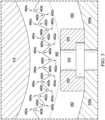
- FIGURE 5 illustrates an enlarged view of the control system of FIGURE 4 , showing the mesh of the splines on sleeve 460 and tilt ball 462.
- the spline surfaces of sleeve 460 and tilt ball 462 may be treated with an appropriate surface treatment or coating to reduce wear and friction between the parts.
- sleeve 460 and/or tilt ball 462 may be anodized.
- Anodization is an electrolyte passivation process used to increase the thickness of the natural oxide layer on the surface of metal parts.
- sleeve 460 and/or tilt ball 462 may be treated using a process called Keronite, which may produce a hard, dense ceramic surface layer on sleeve 460 and/or tilt ball 462.
- the splines on sleeve 460 and tilt ball 462 have sharp peaks, but may have a variety of interlocking shapes.
- FIGURE 6 illustrates an alternative embodiment of an anti-drive mechanism. Illustrated in FIGURE 6 is an anti-drive mechanism that includes a key-and-slot combination instead of the spline configuration of FIGURES 3-5 .
- the key-and-slot configuration may be much simpler than the spline configuration disclosed above.
- a set of three keys 616 are attached to top case 624.
- keys 616 are located radially equidistantly around the circumference of top case 624.
- Keys 616 are attached to top case 624, thus, in some embodiments, eliminating the need for a full sleeve mechanism that may be necessary for the spline configuration above. Note, however, that this embodiment is not incompatible with a sleeve configuration. In some examples, a sleeve could be provided with the necessary keys.
- tilt ball 604 sits around a top case 624 for the gearbox, which is illustrated in more detail in FIGURES 8 and 9 .
- Tilt ball 604 includes slots that mate to key 616 in a key and slot system. Keys 616 run axially along the top case 624 and guide bearings 618 to ensure that tilt ball 604 does not bind, and to permit axial movement up and down top case 624. The spacing may be selected to be near enough to effectively provide an anti-drive mechanism for tilt ball 604 to ensure that tilt ball 604 does not rotate relative to top case 624. While three keys are illustrated here by way of example, more or fewer keys may be provided in other embodiments. The number of keys used may be selected according to criteria such as the desires strength of the anti-drive, and the desired weight characteristics.
- tilt ball 604 sits around top case 624 for the gearbox illustrated in more detail in FIGURES 8 and 9 .
- Tilt ball 604 includes three slots 612 that mate to keys 616 in a key-and-slot system. Keys 616 run axially along top case 624, and guide bearings 618 mate tilt ball 604 to keys 616. There is enough spacing provided between key 616 and guide bearing 618 to ensure that tilt ball 604 does not bind, and to permit axial movement up and down top case 624. However, the spacing is near enough to effectively provide an anti-drive mechanism for tilt ball 604 to ensure that tilt ball 604 does not rotate relative to top case 624. In an illustrative embodiment, the spacing between key 616 and slot 612 may be less than approximately 1 mm.
- top case 624 may provide a non-loadbearing floating insert 624a along with fasteners 625 that are a second retaining feature for key 616 and top case 624.
- Stop surface on key 616a ensures that tilt ball 604 does not slide down to or past top case 624.
- the drive shaft is disposed within top case 624, and may pass through the center of top case 624.
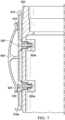
- FIGURE 7 illustrates a cutaway view of select elements of the anti-drive mechanism of FIGURE 6 . Visible in this FIGURE are tilt ball 604, guide bearings 618, and key 616. FIGURE 7 illustrates the alignment of the various elements, how key 616 is attached to top case 624, and how guide bearing 618 in tilt ball 604 functions on key 616. As described above, this permits tilt ball 604 to move axially along key 616 attached to top case 624, while preventing rotation of tilt ball 604 relative to top case 624.
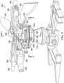
- FIGURE 8 illustrates an example helicopter rotor assembly 800.
- Helicopter rotor assembly 800 represents a simplified version of the helicopter rotor assembly of FIGURE 9 .
- helicopter rotor assembly 800 includes a power train 805, a drive shaft 810, a rotor hub assembly 820, blades 830, a swashplate 840, and pitch links 850.
- helicopter rotor assembly 800 may include more or fewer components.
- FIGURE 8 does not show components such as a gearbox, a yoke, drive links, drive levers, and other components, such as those illustrated in the rotor assembly of FIGURE 9 that may be incorporated.
- Power train 805, drive shaft 810, and rotor hub assembly 820 are mechanical components for transmitting torque and/or rotation.
- Power train 805 may include a variety of component, including an engine, a transmission, and differentials.
- drive shaft 810 receives torque or rotational energy from power train 805 and rotates rotor hub assembly 820. Rotation of rotor hub assembly 820 causes blades 830 to rotate about drive shaft 810.
- Swashplate 840 translates helicopter flight control input into motion of blades 830.
- swashplate 840 may transmit flight control input from the non-rotating fuselage to the rotating drive assembly 820 and/or blades 830.
- Swashplate 840 includes a non-rotating swashplate ring 840a and a rotating swashplate ring 840b.
- Non-rotating swashplate ring 840a does not rotate with drive shaft 810
- rotating swashplate ring 840b does rotate with drive shaft 810.
- pitch links 850 connect rotating swashplate ring 840b to blades 830.
- translating the non-rotating swashplate ring 840a along the axis of drive shaft 810 causes the pitch links 830 to move up or down. This changes the pitch angle of all blades equally, increasing or decreasing the thrust of the rotor and causing the aircraft to ascend or descend.
- Tilting the non-rotating swashplate ring 840a causes the rotating swashplate 840b to tilt, moving the pitch links up and down cyclically as they rotate with the drive shaft. This tilts the thrust vector of the rotor, causing the aircraft to translate horizontally following the direction the swashplate is tilted.
- non-rotating swashplate ring 840a should not rotate with drive shaft 810, whereas rotating swashplate ring 840b should rotate with drive shaft 810.
- Teachings of certain embodiments provide the capability to prevent a non-rotating swashplate ring from rotating while allowing the rotating swashplate ring to rotate with the rotor blades. A particular embodiment is described below with regard to FIGURE 9 .
- FIGURE 9 illustrates a rotor system 900, according to one example embodiment.
- Rotor system 900 features a drive shaft 910, a gearbox 915, a yoke 920, grips 925, blades 930, a swashplate 940 having a non-rotating swashplate ring 940a and a rotating swashplate ring 940b, pitch links 950, drive levers 952, drive links 954, and a sleeve 960.
- Drive shaft 910, yoke 920, grips 925, drive levers 952, and drive links 954 are mechanical components for transmitting torque and/or rotation.
- grips 925 couple blades 930 to yoke 920, which is coupled to drive shaft 910.
- Drive levers 952 and drive links 954 couple yoke 920 to rotating swashplate ring 940b.
- drive shaft 910 receives torque or rotational energy and rotates yoke 920.
- Rotation of yoke 920 causes grips 925 to rotate blades 930 and causes drive levers 952 and drive links 954 to rotate rotating swashplate ring 940b.
- Swashplate 940 translates flight control input into motion of blades 930. Because blades 930 are typically spinning when the helicopter is in flight, swashplate 940 may transmit flight control input from the non-rotating fuselage to the rotating yoke 920, grips 925, and/or blades 930.
- Swashplate 940 includes a non-rotating swashplate ring 940a and a rotating swashplate ring 940b.
- Non-rotating swashplate ring 940a does not rotate with drive shaft 910, whereas rotating swashplate ring 940b does rotate with drive shaft 910.
- Rotating swashplate ring 940b may be coupled to blades 930 via pitch links 950, which allow rotating swashplate ring 940b to control deflection of blades 930.
- translating or tilting non-rotating swashplate ring 940a causes rotating swashplate ring 940b to translate or tilt, which in turn moves pitch links 950 up and down.
- Sleeve 960 is coupled to and around gearbox 915.
- sleeve 960 is substantially cylindrical.
- Gearbox 915 surrounds drive shaft 910 and separates rotating drive shaft 910 from non-rotating components such as sleeve 960 and non-rotating swashplate ring 940a.
- Sleeve 960 prevents non-rotating swashplate ring 940a from rotating with drive shaft 910.
- using sleeve 960 to prevent rotating of non-rotating swashplate ring 940a may allow for a shorter rotor system 900.
- sleeve 960 may eliminate the need to externally couple non-rotating swashplate ring 940a directly to gearbox 915. If non-rotating swashplate ring 940a is not coupled directly to gearbox 215, then the overall size and height of rotor system 900 may be reduced.
- FIGURES illustrate the architecture, functionality, and operation of possible implementations of various embodiments of the present disclosure. It should also be noted that, in some alternative implementations, the function(s) associated with a particular block may occur out of the order specified in the FIGURES. For example, two blocks shown in succession may, in fact, be executed substantially concurrently, or the blocks may sometimes be executed in the reverse order or alternative orders, depending upon the functionality involved.
- each of the expressions "at least one of X, Y and Z,” “at least one of X, Y or Z,” “one or more of X, Y and Z,” “one or more of X, Y or Z” and "A, B and/or C” can mean any of the following: 1) X, but not Y and not Z; 2) Y, but not X and not Z; 3) Z, but not X and not Y; 4) X and Y, but not Z; 5) X and Z, but not Y; 6) Y and Z, but not X; or 7) X, Y, and Z.
- first and second are intended to distinguish the particular nouns (e.g., blade, rotor, element, device, condition, module, activity, operation, etc.) they modify. Unless expressly stated to the contrary, the use of these terms is not intended to indicate any type of order, rank, importance, temporal sequence, or hierarchy of the modified noun.
- first X and second X are intended to designate two X elements that are not necessarily limited by any order, rank, importance, temporal sequence, or hierarchy of the two elements.
- “at least one of,” “one or more of,” and the like can be represented using the “(s)” nomenclature (e.g., one or more element(s)).
Landscapes
- Engineering & Computer Science (AREA)
- Mechanical Engineering (AREA)
- Aviation & Aerospace Engineering (AREA)
- Transmission Devices (AREA)
Description
- This disclosure relates generally to aeronautical engineering, and more particularly, though not exclusively, to a swashplate system for providing an anti-drive mechanism for rotary aircraft control.
- Rotary wing aircraft may be used to perform a variety of tasks requiring a high degree of functional flexibility.
-
US6149386A discloses swash-plates oscillating mounted by the non-rotating plate on a central ball joint sliding axially around a guide fixed to the structure and on which the ball joint is locked from rotation by internal splines engaging external splines of the guide. Two cotters slide in diametrically opposite grooves in the external face of the ball joint, and the non-rotating plate pivots on trunnions of the cotters around one of two perpendicular axes the other of which an axis around which the cotters pivot and which is perpendicular to the rotor axis. -
US6074168A discloses rotating and non-rotating swash-plates that are guided in axial translation and in tilting on the rotor axis by a non-rotating axial guide arrangement, such as two pillars, and slides on each of which slides one of two pads carrying diametrically opposite trunnions, enabling the pivoting of the non-rotating plate around a first diametrical axis, whereas the sliding movements of the pads on the slides guide the pivoting movements of the non-rotating plate around a second diametrical axis perpendicular to the rotor axis and first diametrical axis, and which is the axis of the cylindrical face of the slides. -
EP2679493B1 discloses a constraint assembly for an aircraft, having a first member; a second member mounted to translate along and rotate about its own axis (A); and connecting means for connecting the first and second member / to prevent rotation of the second member about the axis (A) with respect to the first member; the connecting means having a retaining arm, which projects outwards from one of the first and second member, and extends at a distance of other than zero from the axis (A); and an antirotation bracket, which projects from the other of the first and second member, extends at a distance of other than zero from the axis (A), and defines a through opening engaged in sliding manner by the retaining arm. -
US20130149150A1 discloses a rotor system, comprising a mating element, a sleeve, a first swashplate ring, a locking element, and a second swashplate ring. The mating element having a first plurality of grooves a first plurality of ridges. The sleeve is positioned inside the mating element such that the sleeve prevents rotation of the mating element about the sleeve while allowing the mating element to translate along the sleeve. The sleeve has a second plurality of grooves mating with the first plurality of ridges and a second plurality of ridges mating with the first plurality of grooves. The first swashplate ring is positioned around the mating element, and the locking element prevents the first swashplate ring from rotating about the sleeve. The second swashplate ring is rotatable about the sleeve. -
US9151162B2 - Aspects of the present invention are set out in the appended claims. Optional features are set out in the dependent claims.
-
-
FIGURE 1 illustrates an example embodiment of a rotorcraft -
FIGURE 2 illustrates a perspective view of an example tiltrotor aircraft. -
FIGURE 3 illustrates a longitudinal cross-section of an example rotor system. -
FIGURE 4 illustrates a transverse cross-section of an example rotor system. -
FIGURE 5 illustrates a detail view of the transverse cross-section of the rotor system ofFIGURE 4 . -
FIGURE 6 illustrates an alternative embodiment of an anti-drive mechanism. -
FIGURE 7 illustrates a cutaway view of select elements of the anti-drive mechanism ofFIGURE 6 . -
FIGURE 8 illustrates an example helicopter rotor assembly. -
FIGURE 9 illustrates a rotor system, according to one example embodiment. - The following disclosure describes various illustrative embodiments and examples for implementing the features and functionality of the present disclosure. While particular components, arrangements, and/or features are described below in connection with various example embodiments, these are merely examples used to simplify the present disclosure and are not intended to be limiting. It will of course be appreciated that in the development of any actual embodiment, numerous implementation-specific decisions must be made to achieve the developer's specific goals, including compliance with system, business, and/or legal constraints, which may vary from one implementation to another. Moreover, it will be appreciated that, while such a development effort might be complex and time-consuming, it would nevertheless be a routine undertaking for those of ordinary skill in the art having the benefit of this disclosure.
- In the specification, reference may be made to the spatial relationships between various components and to the spatial orientation of various aspects of components as depicted in the attached drawings. However, as will be recognized by those skilled in the art after a complete reading of the present disclosure, the devices, components, members, apparatuses, etc. described herein may be positioned in any desired orientation. Thus, the use of terms such as "above," "below," "upper," "lower," or other similar terms to describe a spatial relationship between various components or to describe the spatial orientation of aspects of such components, should be understood to describe a relative relationship between the components or a spatial orientation of aspects of such components, respectively, as the components described herein may be oriented in any desired direction.
- Further, the present disclosure may repeat reference numerals and/or letters in the various examples. This repetition is for the purpose of simplicity and clarity and does not in itself dictate a relationship between the various embodiments and/or configurations discussed.
- Example embodiments that may be used to implement the features and functionality of this disclosure will now be described with more particular reference to the attached FIGURES.
-
FIGURE 1 illustrates an example embodiment of arotorcraft 101.Rotary aircraft 101 could be either a manned or an unmanned rotary aircraft. In some cases,rotary aircraft 101 could be electrically powered instead of powered by jet fuel. In those cases,rotary aircraft 101 could either be designed from the start with an in-air recharging system, or it could be modified after production with an aftermarket in-air recharging system. - In cases where
rotary aircraft 101 is powered by jet fuel, it could be modified to serve as a tanker for in-air recharging of electrical aircraft such as electrically powered drones. For example,rotary aircraft 101 could include a generator that converts its jet fuel power into electrical power, and that electrical power could be shared with electrical aircraft such as drones. - The illustrated example portrays a side view of
rotorcraft 101. Rotorcraft 101 includes arotor system 103 with a plurality ofrotor blades 111. The pitch of eachrotor blade 111 can be managed or adjusted in order to selectively control direction, thrust, and lift ofrotorcraft 101. Rotorcraft 101 further includes afuselage 105 and atail structure 109. In the illustrated embodiment,tail structure 109 may be used as a horizontal stabilizer. Torque is supplied torotor system 103 using at least one engine. In this illustration,rotor blades 111 form a motive subsystem, or in other words, a subsystem that provides the motive force to move the aircraft. The controls that manage or adjust the control direction form a control subsystem, which can include manual user controls, as well as computer augmentation to manual user control. Furthermore, in some embodiments, rotorcraft 101 may be an autonomous drone vehicle, or a remote-controlled drone vehicle, in which case some control functions are provided by a computer. -
FIGURE 2 illustrates a perspective view of anexample tiltrotor aircraft 201.Tiltrotor aircraft 201 could be either a manned or an unmanned rotary aircraft. In some cases,tiltrotor aircraft 201 could be electrically powered instead of powered by jet fuel. In those cases,tiltrotor aircraft 201 could either be designed from the start with an in-air recharging system, or it could be modified after production with an aftermarket in-air recharging system. - In cases where
tiltrotor aircraft 201 is powered by jet fuel, it could be modified to serve as a tanker for in-air recharging of electrical aircraft such as electrically powered drones. For example,tiltrotor aircraft 201 could include a generator that converts its jet fuel power into electrical power, and that electrical power could be shared with electrical aircraft such as drones. - Tiltrotor
aircraft 201 includesnacelles wing 205, and afuselage 207. - Each
nacelle rotor blades 211. Moreover, eachnacelle rotor blades 211. In some embodiments,nacelles nacelles nacelles - It should be appreciated that
rotorcraft 101 ofFIGURE 1 andtiltrotor aircraft 201 ofFIGURE 2 are merely illustrative of a variety of aircraft that can be used to implement embodiments of the present disclosure. Other aircraft implementations can include, for example, fixed-wing airplanes, hybrid aircraft, unmanned aircraft, gyrocopters, a variety of helicopter configurations, and drones, among other examples. - In this illustration,
rotor blades 211 form a motive subsystem, or in other words, a subsystem that provides the motive force to move the aircraft. The controls that manage or adjust the control direction form a control subsystem, which can include manual user controls, as well as computer augmentation to manual user control. Furthermore, in some embodiments,tiltrotor aircraft 201 may be an autonomous drone vehicle, or a remote-controlled drone vehicle, in which case some control functions are provided by a computer. - Control of an illustrative rotary aircraft includes the use of pilot inputs, such as via a control yoke. Pilot inputs on the control yoke are translated to movement via actuators that act on a swashplate. A typical swashplate includes a rotating ring that rotates with the rotors and the driveshaft. The top case, outer housing (tilt ball) and a non-rotating ring do not rotate. The rotating ring and the non-rotating ring may be joined to one another, for example, via a duplex or triplex bearing. In an illustrative embodiment, a tilt ball is disposed around the top case as an exterior casing, and acts essentially as a large bearing for the control system.
- In an embodiment, three actuators input loads to change the pitch of the blades. These actuators translate and tilt the swashplate, and the swashplate translates this movement into displacement of the rotors. For changes to so-called collective blade pitch, the entire rotor moves jointly in a single direction. For example, to induce forward motion in the rotary aircraft, the swashplate tilts forward. When the tilt ball and swashplate move up the top case axially, it will increase the angle of attack on all blades and produce an upward vertical motion.
- The swashplate and tilt ball may also be used to produce cyclic blade pitch. In contrast to collective blade pitch, cyclic blade pitch is not a gross movement of the entire rotor mechanism. Rather, one or more of the actuators moves and acts on the swashplate, and tilts the swashplate about the tilt ball. As the swashplate tilts the rotor follows the tilt, while pitch links on the swashplate transmit pitch information to the blades. Therefore, when a pitch link dips down, this decreases the pitch on the blade. If a pitch link tilts up, it increases the pitch on that blade. This combination of collective blade pitch and cyclic blade pitch produces an input and the aircraft follows the direction of the control input.
- To maintain this control, the non-rotating ring of the swashplate receives control inputs and translates them to the rotating ring. For this to operate mechanically as intended, the non-rotating ring should not rotate about or relative to the tilt ball and/or the top case. Rather, the non-rotating ring should remain rotationally static. However, when actuators displace the swashplate, this motion tends to try to drive the non-rotating ring and make it rotate relative to the tilt ball.
- To prevent the tilt ball from rotating relative to the top case, an anti-drive mechanism or anti-drive means may be employed. The anti-drive means essentially lock the tilt ball into place relative to the top case. To preserve the collective pitch motion, which requires the tilt ball to slide axially relative to the top case, the anti-drive means should permit this axial motion.
- An existing solution is the use of a sliding spline that locks out rotation between the tilt ball and the gearbox. This sliding spline may be provided via an external casing on the gearbox, which may typically be constructed of aluminum. Such a spline mechanism is illustrated in
FIGURES 3 ,4 , and5 of the present specification, described in greater detail below. This spline mechanism provides effective anti-drive means to prevent the tilt ball from rotating relative to the gearbox. It also advantageously provides the translatable axial motion up and down the gearbox. - However, this spline configuration can be improved. For example, the joint at the splines experiences substantial wear when the aircraft is in service. Thus, the spline teeth may require a wear coating to prevent degradation and to preserve performance. Because of the complex geometry of the spline, it is easiest to plate the spline, such as by hard anodizing the aluminum. However, this hard anodizing reduces the strength of the aluminum and hastens metal fatigue.
- Steel is a more durable option than aluminum, and advantageously can take a thin, dense chrome plating as a wear coating. This provides a more durable anti-drive mechanism than hard anodized aluminum. However, steel is much heavier than aluminum. In an illustrative example, the sleeve around the gearbox that provides the spline mechanism has a diameter of approximately 18 inches, and similarly, a height of approximately 18 inches (approximately 203mm). If this sleeve were constructed of steel, it would contribute approximately 50 to 60 pounds (approximately 23 to 27 kg) of weight to the rotary aircraft, thus reducing its payload capacity or airlift capacity by a corresponding 50 to 60 pounds.
- It is therefore beneficial to have an anti-drive means that can be constructed of steel, thus providing for greater durability and strength, and an improved wear coating such as chrome plating, while also not adding as much weight to the aircraft.
- As illustrated in
FIGURES 6 and7 of the present specification, described in greater detail below, the spline mechanism illustrated inFIGURES 3 - 5 can be supplemented, or even completely replaced, with a key-and-slot mechanism. Advantageously, the key-and-slot mechanism does not require a full exterior sleeve around the top case. Rather, keys (for example, three keys) are attached directly to the top case of the gearbox. These keys may have a length of approximately the same height as the top case, and are configured to engage internal slots on the tilt ball. Because these keys do not require a full sleeve around the top case, they can be constructed of a material, such as steel, without contributing substantial weight to the aircraft. For example, in an illustrative embodiment, three such keys can be attached equidistantly, radially around the top case. These three steel keys may have a thin, dense chrome plating as a wear surface, and in total contribute only an additional 4 to 5 pounds (1.8 to 2.3 kg) to the weight of the aircraft, as opposed to 50 to 60 pounds (23 to 27 kg) in the case of a full steel sleeve around the top case. - An advantage to the key-slot arrangement is that the simple geometry of the key allows the use of an aluminum key with a tungsten carbide coating. Applying this coating generally includes grinding the part to a close tolerance before and after application. The complexity of a splined interface makes it difficult to apply such a coating, while the flat surfaces of the key are well-suited for the use of tungsten carbide.
- These keys mate to corresponding slots in the tilt ball. Guide bearings may be used as a replaceable wear item in the slots of the tilt ball mating with the keys. As a secondary retention feature, fasteners may be used in the holes of the top case. These fasteners are not intended to bear the load of the anti-drive mechanism, but as a secondary retention feature using floating inserts to prevent loading of the fasteners. Advantageously, the key and slot configuration can be manufactured relatively easily, and does not require specialized machining, which may be necessary for the spline configuration. It should be noted, however, that the key-and-slot configuration and the spline configuration are not mutually exclusive. A spline configuration could be used in conjunction with a key-and-slot configuration, or the key-and-slot configuration could be used instead of the spline configuration.
-
FIGURE 3 illustrates a longitudinal cross-section of an example rotor control system not presently being claimed. -
FIGURES 8 and9 below provide some contextual illustration of how the mechanism ofFIGURES 3 and4 would relate to the rest of the rotor system. As shown inFIGURE 3 ,tilt ball 362 surrounds and mates tosleeve 360. In operation,sleeve 360 prevents rotation oftilt ball 362 abouttop case 315.Sleeve 360 may also allowtilt ball 362 to translate axially onsleeve 360. -
Non-rotating ring 340a is positioned aroundtilt ball 362. In the example ofFIGURE 3 ,pin 342 and key 344 preventnon-rotating ring 340a from rotating about the longitudinal axis oftilt ball 362 while allowing it to rotate around the spherical surface oftilt ball 362. In this example, key 344 fits within an external slot intilt ball 362.Key 344 is configured to receivepin 342.Non-rotating ring 340a is also configured to receivepin 342, and pin 342 preventstilt ball 362 andnon-rotating ring 340a from rotating relative to one another. -
Tilt ball 362 may include a spherical outer surface. This spherical outer surface allows swashplate 340 to rotate about the spherical shape oftilt ball 362. As stated above, rotation ofnon-rotating ring 340a causesrotating ring 340b to rotate, which in turn translatespitch links 350 up and down and feathers blades 330. Thus, teachings of certain embodiments recognize the capability to prevent radial rotation ofnon-rotating ring 340a while allowing rotation ofnon-rotating ring 340a about the spherical surface oftilt ball 362. - Bearing 346 separates
tilt ball 362 andnon-rotating ring 340a. In some embodiments, bearing 346 allowsnon-rotating ring 340a to rotate about the spherical shape oftilt ball 362. Bearing 346 is a replaceable wear item and may be made of any suitable bearing material, such as Teflon. - Rotating
ring 340b is positioned aroundnon-rotating ring 340a. Bearing 348 separatesnon-rotating ring 340a from rotatingring 340b and allowsrotating ring 340b to rotate relative tonon-rotating ring 340a. In operation, rotatingring 340b rotates withdrive levers 352 and drivelinks 354. Rotatingring 340b also translates axially withnon-rotating ring 340a asnon-rotating ring 340a rotates about the spherical surface oftilt ball 362. -
FIGURE 4 illustrates a transverse cross-section of an example control system not presently being claimed. As shown inFIGURE 4 ,top case 415 surroundsdrive shaft 410.Sleeve 460 is attached to and aroundtop case 415.Tilt ball 462 is attached tosleeve 460 such thatsleeve 460 prevents rotation oftilt ball 462 abouttop case 415.Non-rotating ring 440a is positioned aroundtilt ball 462.Pin 442 and key 444 preventnon-rotating ring 440a from rotating aroundtop case 415. Rotatingring 440b is positioned aroundnon-rotating ring 440a, and is free to rotate aroundnon-rotating ring 440a with the use ofbearing 448. - As shown in
FIGURE 4 ,sleeve 460 includes splines that mate with splines ontilt ball 462. In the example ofFIGURE 4 , the splines onsleeve 460 are continuous around the outer diameter ofsleeve 460, and the splines ontilt ball 462 are continuous around the inner diameter oftilt ball 462. The splines onsleeve 460 andtilt ball 462 are shown in greater detail inFIGURE 5 . - In some examples, the splines of
sleeve 460 andtilt ball 462 provide direct contact betweensleeve 460 andtilt ball 462. Direct contact may allow the outer diameter oftilt ball 462 to be reduced. In turn, this may allow the diameters of non-rotating ring 442a and rotating ring 442b to be reduced. Accordingly, teachings of certain examples recognize that using splines may reduce the outer diameter of swashplate 440. -
FIGURE 5 illustrates an enlarged view of the control system ofFIGURE 4 , showing the mesh of the splines onsleeve 460 andtilt ball 462. - In some examples, the spline surfaces of
sleeve 460 andtilt ball 462 may be treated with an appropriate surface treatment or coating to reduce wear and friction between the parts. For example,sleeve 460 and/ortilt ball 462 may be anodized. Anodization is an electrolyte passivation process used to increase the thickness of the natural oxide layer on the surface of metal parts. In one example example,sleeve 460 and/ortilt ball 462 may be treated using a process called Keronite, which may produce a hard, dense ceramic surface layer onsleeve 460 and/ortilt ball 462. - In the example of
FIGURE 5 , the splines onsleeve 460 andtilt ball 462 have sharp peaks, but may have a variety of interlocking shapes. -
FIGURE 6 illustrates an alternative embodiment of an anti-drive mechanism. Illustrated inFIGURE 6 is an anti-drive mechanism that includes a key-and-slot combination instead of the spline configuration ofFIGURES 3-5 . - As can be seen in
FIGURE 6 , the key-and-slot configuration may be much simpler than the spline configuration disclosed above. In this illustration, a set of threekeys 616 are attached totop case 624. In this illustration,keys 616 are located radially equidistantly around the circumference oftop case 624.Keys 616 are attached totop case 624, thus, in some embodiments, eliminating the need for a full sleeve mechanism that may be necessary for the spline configuration above. Note, however, that this embodiment is not incompatible with a sleeve configuration. In some examples, a sleeve could be provided with the necessary keys. - In this illustration,
tilt ball 604 sits around atop case 624 for the gearbox, which is illustrated in more detail inFIGURES 8 and9 .Tilt ball 604 includes slots that mate to key 616 in a key and slot system.Keys 616 run axially along thetop case 624 and guidebearings 618 to ensure thattilt ball 604 does not bind, and to permit axial movement up and downtop case 624. The spacing may be selected to be near enough to effectively provide an anti-drive mechanism fortilt ball 604 to ensure thattilt ball 604 does not rotate relative totop case 624. While three keys are illustrated here by way of example, more or fewer keys may be provided in other embodiments. The number of keys used may be selected according to criteria such as the desires strength of the anti-drive, and the desired weight characteristics. - In this illustration,
tilt ball 604 sits aroundtop case 624 for the gearbox illustrated in more detail inFIGURES 8 and9 .Tilt ball 604 includes threeslots 612 that mate tokeys 616 in a key-and-slot system.Keys 616 run axially alongtop case 624, and guidebearings 618mate tilt ball 604 tokeys 616. There is enough spacing provided betweenkey 616 and guide bearing 618 to ensure thattilt ball 604 does not bind, and to permit axial movement up and downtop case 624. However, the spacing is near enough to effectively provide an anti-drive mechanism fortilt ball 604 to ensure thattilt ball 604 does not rotate relative totop case 624. In an illustrative embodiment, the spacing betweenkey 616 andslot 612 may be less than approximately 1 mm. - There is illustrated in this embodiment the use of bosses on
key 616 and holes intop case 624. Holes intop case 624 may provide anon-loadbearing floating insert 624a along withfasteners 625 that are a second retaining feature forkey 616 andtop case 624. - Also illustrated in this embodiment is the use of a stop surface on key 616a to provide a lower bound to the axial movement of
tilt ball 604 alongtop case 624. Stop surface on key 616a ensures thattilt ball 604 does not slide down to or pasttop case 624. - Although not seen in this FIGURE, the drive shaft is disposed within
top case 624, and may pass through the center oftop case 624. -
FIGURE 7 illustrates a cutaway view of select elements of the anti-drive mechanism ofFIGURE 6 . Visible in this FIGURE aretilt ball 604, guidebearings 618, andkey 616.FIGURE 7 illustrates the alignment of the various elements, how key 616 is attached totop case 624, and how guide bearing 618 intilt ball 604 functions onkey 616. As described above, this permitstilt ball 604 to move axially alongkey 616 attached totop case 624, while preventing rotation oftilt ball 604 relative totop case 624. -
FIGURE 8 illustrates an examplehelicopter rotor assembly 800.Helicopter rotor assembly 800 represents a simplified version of the helicopter rotor assembly ofFIGURE 9 . InFIGURE 8 ,helicopter rotor assembly 800 includes apower train 805, adrive shaft 810, arotor hub assembly 820,blades 830, aswashplate 840, and pitch links 850. In some examples,helicopter rotor assembly 800 may include more or fewer components. For example,FIGURE 8 does not show components such as a gearbox, a yoke, drive links, drive levers, and other components, such as those illustrated in the rotor assembly ofFIGURE 9 that may be incorporated. -
Power train 805,drive shaft 810, androtor hub assembly 820 are mechanical components for transmitting torque and/or rotation.Power train 805 may include a variety of component, including an engine, a transmission, and differentials. In operation, driveshaft 810 receives torque or rotational energy frompower train 805 and rotatesrotor hub assembly 820. Rotation ofrotor hub assembly 820 causesblades 830 to rotate aboutdrive shaft 810. -
Swashplate 840 translates helicopter flight control input into motion ofblades 830. - Because
blades 830 are typically spinning when the helicopter is in flight,swashplate 840 may transmit flight control input from the non-rotating fuselage to therotating drive assembly 820 and/orblades 830. -
Swashplate 840 includes anon-rotating swashplate ring 840a and arotating swashplate ring 840b. Non-rotating swashplate ring 840a does not rotate withdrive shaft 810, whereas rotatingswashplate ring 840b does rotate withdrive shaft 810. In the example ofFIGURE 8 , pitch links 850 connect rotatingswashplate ring 840b toblades 830. - In operation, according to one example embodiment, translating the non-rotating swashplate ring 840a along the axis of
drive shaft 810 causes the pitch links 830 to move up or down. This changes the pitch angle of all blades equally, increasing or decreasing the thrust of the rotor and causing the aircraft to ascend or descend. Tilting the non-rotating swashplate ring 840a causes therotating swashplate 840b to tilt, moving the pitch links up and down cyclically as they rotate with the drive shaft. This tilts the thrust vector of the rotor, causing the aircraft to translate horizontally following the direction the swashplate is tilted. - In the example of
FIGURE 8 , non-rotating swashplate ring 840a should not rotate withdrive shaft 810, whereas rotatingswashplate ring 840b should rotate withdrive shaft 810. Teachings of certain embodiments provide the capability to prevent a non-rotating swashplate ring from rotating while allowing the rotating swashplate ring to rotate with the rotor blades. A particular embodiment is described below with regard toFIGURE 9 . -
FIGURE 9 illustrates arotor system 900, according to one example embodiment. -
Rotor system 900 features adrive shaft 910, agearbox 915, ayoke 920, grips 925,blades 930, aswashplate 940 having anon-rotating swashplate ring 940a and arotating swashplate ring 940b, pitch links 950, drive levers 952, drivelinks 954, and asleeve 960. - Drive
shaft 910,yoke 920, grips 925, drive levers 952, and drivelinks 954 are mechanical components for transmitting torque and/or rotation. Inrotor system 900,grips 925couple blades 930 toyoke 920, which is coupled to driveshaft 910. Drive levers 952 and drivelinks 954couple yoke 920 to rotatingswashplate ring 940b. In operation, driveshaft 910 receives torque or rotational energy and rotatesyoke 920. Rotation ofyoke 920 causesgrips 925 to rotateblades 930 and causes drivelevers 952 and drivelinks 954 to rotate rotatingswashplate ring 940b. -
Swashplate 940 translates flight control input into motion ofblades 930. Becauseblades 930 are typically spinning when the helicopter is in flight,swashplate 940 may transmit flight control input from the non-rotating fuselage to therotating yoke 920, grips 925, and/orblades 930. -
Swashplate 940 includes anon-rotating swashplate ring 940a and arotating swashplate ring 940b. Non-rotating swashplate ring 940a does not rotate withdrive shaft 910, whereas rotatingswashplate ring 940b does rotate withdrive shaft 910. Rotatingswashplate ring 940b may be coupled toblades 930 viapitch links 950, which allow rotatingswashplate ring 940b to control deflection ofblades 930. In operation, translating or tilting non-rotating swashplate ring 940a causes rotatingswashplate ring 940b to translate or tilt, which in turn moves pitchlinks 950 up and down. -
Sleeve 960 is coupled to and aroundgearbox 915. In the illustrated embodiment,sleeve 960 is substantially cylindrical.Gearbox 915 surroundsdrive shaft 910 and separatesrotating drive shaft 910 from non-rotating components such assleeve 960 and non-rotating swashplate ring 940a. -
Sleeve 960 prevents non-rotating swashplate ring 940a from rotating withdrive shaft 910. In some embodiments, usingsleeve 960 to prevent rotating of non-rotating swashplate ring 940a may allow for ashorter rotor system 900. For example, in some embodiments,sleeve 960 may eliminate the need to externally couple non-rotating swashplate ring 940a directly togearbox 915. If non-rotating swashplate ring 940a is not coupled directly to gearbox 215, then the overall size and height ofrotor system 900 may be reduced. - The flowcharts and diagrams in the FIGURES illustrate the architecture, functionality, and operation of possible implementations of various embodiments of the present disclosure. It should also be noted that, in some alternative implementations, the function(s) associated with a particular block may occur out of the order specified in the FIGURES. For example, two blocks shown in succession may, in fact, be executed substantially concurrently, or the blocks may sometimes be executed in the reverse order or alternative orders, depending upon the functionality involved.
- Although several embodiments have been illustrated and described in detail, numerous other changes, substitutions, variations, alterations, and/or modifications are possible without departing from the scope of the present invention, as defined by the appended claims. The particular embodiments described herein are illustrative only, and may be modified and practiced in different but equivalent manners, as would be apparent to those of ordinary skill in the art having the benefit of the teachings herein.
- Those of ordinary skill in the art would appreciate that the present disclosure may be readily used as a basis for designing or modifying other embodiments for carrying out the same purposes and/or achieving the same advantages of the embodiments introduced herein. For example, certain embodiments may be implemented using more, less, and/or other components than those described herein. Moreover, in certain embodiments, some components may be implemented separately, consolidated into one or more integrated components, and/or omitted. Similarly, methods associated with certain embodiments may be implemented using more, less, and/or other steps than those described herein, and their steps may be performed in any suitable order.
- The diagrams in the FIGURES illustrate the architecture, functionality, and/or operation of possible implementations of various embodiments of the present disclosure.
- Numerous other changes, substitutions, variations, alterations, and modifications may be ascertained to one of ordinary skill in the art and it is intended that the present disclosure encompass all such changes, substitutions, variations, alterations, and modifications insofar as they fall within the scope of the appended claims.
- One or more advantages mentioned herein do not in any way suggest that any one of the embodiments described herein necessarily provides all the described advantages or that all the embodiments of the present disclosure necessarily provide any one of the described advantages. Note that in this specification, references to various features included in "one embodiment," "example embodiment," "an embodiment," "another embodiment," "certain embodiments," "some embodiments," "various embodiments," "other embodiments," "alternative embodiment," and the like are intended to mean that any such features are included in one or more embodiments of the present disclosure, but may or may not necessarily be combined in the same embodiments.
- As used herein, unless expressly stated to the contrary, use of the phrase "at least one of," "one or more of" and "and/or" are open ended expressions that are both conjunctive and disjunctive in operation for any combination of named elements, conditions, or activities. For example, each of the expressions "at least one of X, Y and Z," "at least one of X, Y or Z," "one or more of X, Y and Z," "one or more of X, Y or Z" and "A, B and/or C" can mean any of the following: 1) X, but not Y and not Z; 2) Y, but not X and not Z; 3) Z, but not X and not Y; 4) X and Y, but not Z; 5) X and Z, but not Y; 6) Y and Z, but not X; or 7) X, Y, and Z. Additionally, unless expressly stated to the contrary, the terms "first," "second," "third," etc., are intended to distinguish the particular nouns (e.g., blade, rotor, element, device, condition, module, activity, operation, etc.) they modify. Unless expressly stated to the contrary, the use of these terms is not intended to indicate any type of order, rank, importance, temporal sequence, or hierarchy of the modified noun. For example, "first X" and "second X" are intended to designate two X elements that are not necessarily limited by any order, rank, importance, temporal sequence, or hierarchy of the two elements. As referred to herein, "at least one of," "one or more of," and the like can be represented using the "(s)" nomenclature (e.g., one or more element(s)).
Claims (11)
- A swashplate assembly for a rotary aircraft, comprising:a rotating ring configured to rotate with a drive shaft of the rotary aircraft;a non-rotating ring coupled to the rotating ring and rotationally decoupled from the rotating ring, wherein the non-rotating ring does not rotate with the rotating ring and drive shaft;a gearbox top case (624) configured to surround the drive shaft;a tilt ball (604) disposed around the gearbox top case (624); andan anti-drive mechanism to maintain the tilt ball (604) rotationally stationary relative to the gearbox top case (624), the anti-drive mechanism comprising a key and slot system between the gearbox top case (624) and the tilt ball (604), wherein the tilt ball (604) contains slots (612) of the key-and-slot system to mate with keys (616) of the key-and-slot system;characterised in that the keys (616) are attached directly to the gearbox top case (624).
- The swashplate assembly of claim 1, wherein the non-rotating ring is coupled to the rotating ring via a duplex or triplex bearing.
- The swashplate assembly of claim 1 or claim 2, further comprising a plurality of key-and-slot pairs.
- The swashplate assembly of claim 3, wherein the key-and-slot pairs are disposed substantially equidistantly around a circumference of the gearbox top case.
- The swashplate assembly of any one of claims 1-3, wherein the keys (616) of the key-and-slot system are located on a circumference of the gearbox top case (624).
- The swashplate assembly of claim 5, wherein each key (616) is steel
- The swashplate assembly of claim 5, wherein each key (616) further comprises a chrome wear surface.
- The swashplate assembly of claim 5, wherein each key (616) is aluminum, and preferably further comprising a tungsten carbide coating on each aluminum key
- The swashplate assembly of any preceding claim, wherein slots of the key-and-slot system comprise replaceable wear items comprising a polytetrafluoroethylene liner, and/or further comprising pins and keys to align the tilt ball (604) with the non-rotating ring.
- A rotary aircraft, comprising:an airframe;a main rotor assembly;a gearbox and drive shaft to drive the main rotor assembly;a pilot control input; anda swashplate assembly to translate pilot control inputs to motion of the main rotor assembly, wherein the swashplate assembly is according to claim 1, wherein the rotating ring is configured to engage the main rotor assembly and wherein the tilt ball (604) is mechanically coupled to the non-rotating ring to prevent the tilt ball (604) and non-rotating ring from rotating relative to one another.
- The rotary aircraft of claim 10, wherein the non-rotating ring is coupled to the rotating ring via a duplex or triplex bearing.
Applications Claiming Priority (1)
| Application Number | Priority Date | Filing Date | Title |
|---|---|---|---|
| US16/894,321 US11440653B2 (en) | 2020-06-05 | 2020-06-05 | Anti-drive mechanism for rotary aircraft control |
Publications (2)
| Publication Number | Publication Date |
|---|---|
| EP3919380A1 EP3919380A1 (en) | 2021-12-08 |
| EP3919380B1 true EP3919380B1 (en) | 2024-08-21 |
Family
ID=75111431
Family Applications (1)
| Application Number | Title | Priority Date | Filing Date |
|---|---|---|---|
| EP21163593.3A Active EP3919380B1 (en) | 2020-06-05 | 2021-03-19 | Anti-drive mechanism for rotary aircraft control |
Country Status (2)
| Country | Link |
|---|---|
| US (1) | US11440653B2 (en) |
| EP (1) | EP3919380B1 (en) |
Families Citing this family (2)
| Publication number | Priority date | Publication date | Assignee | Title |
|---|---|---|---|---|
| CN107600415B (en) * | 2017-09-19 | 2023-09-29 | 四川建筑职业技术学院 | Tilting type high-mobility unmanned aerial vehicle adopting cross-pitch-variable rotor wing structure |
| EP4039587A1 (en) * | 2021-02-03 | 2022-08-10 | AIRBUS HELICOPTERS DEUTSCHLAND GmbH | A swashplate assembly with integrated electric motor |
Family Cites Families (13)
| Publication number | Priority date | Publication date | Assignee | Title |
|---|---|---|---|---|
| US2973815A (en) * | 1957-11-08 | 1961-03-07 | Omega Aircraft Corp | Pitch control mechanism for helicopter rotors |
| US3841586A (en) * | 1973-04-26 | 1974-10-15 | Boeing Co | Rotor swashplate assembly |
| FR2661886B1 (en) * | 1990-05-14 | 1992-08-28 | Aerospatiale | DEVICE WITH CYCLIC PLATES MOUNTED ON JOINTS DECOUPLED INTO TANGING AND ROLLING, FOR CONTROLLING THE PITCH OF THE BLADES OF A GIRAVION ROTOR. |
| US5083725A (en) * | 1990-10-11 | 1992-01-28 | United Technologies Corporation | Elastomeric swashplate configuration for helicopters |
| FR2770827B1 (en) * | 1997-11-13 | 2000-01-14 | Eurocopter France | DEVICE WITH SCYCLICAL PLATES FOR CONTROLLING THE PITCH OF THE BLADE OF A ROTOR WITH NON-ROTATING PLATE ARTICULATED BY KEYS ON A CENTRAL BALL JOINT |
| FR2771708B1 (en) * | 1997-12-03 | 2000-02-04 | Eurocopter France | DEVICE WITH SCYCLIC PLATES FOR CONTROLLING THE PITCH OF THE BLADE OF A ROTOR WITH ROTATING GUIDE BODIES ON TRANSLATED SLIDES ACCORDING TO THE AXIS OF THE ROTOR |
| FR2848524B1 (en) * | 2002-12-13 | 2005-12-09 | Eurocopter France | CYCLIC TRAY DEVICE FOR CONTROLLING THE PITCH OF THE BLADES OF A ROTOR OF GIRAVION |
| US8961138B2 (en) * | 2011-12-09 | 2015-02-24 | Bell Helicopter Textron Inc. | Preventing rotation of a fixed ring of a swashplate |
| EP2679493B1 (en) | 2012-06-27 | 2016-04-27 | AGUSTAWESTLAND S.p.A. | Aircraft constraint assembly, and rotor assembly for an aircraft capable of hovering and equipped with such a constraint assembly |
| US9151162B2 (en) * | 2012-11-08 | 2015-10-06 | Bell Helicopter Textron Inc. | Preventing rotation of a fixed ring of a swashplate |
| EP3168146B1 (en) * | 2015-11-11 | 2019-06-05 | kopter group ag | Rotor blade coupling device of a rotor head for a rotorcraft |
| US10161441B2 (en) * | 2016-11-01 | 2018-12-25 | Sikorsky Aircraft Corporation | Self-lubricated bearings |
| US10836479B2 (en) * | 2018-06-19 | 2020-11-17 | Bell Textron Inc. | Rotating swashplate ring to rotor mast connection |
-
2020
- 2020-06-05 US US16/894,321 patent/US11440653B2/en active Active
-
2021
- 2021-03-19 EP EP21163593.3A patent/EP3919380B1/en active Active
Also Published As
| Publication number | Publication date |
|---|---|
| EP3919380A1 (en) | 2021-12-08 |
| US11440653B2 (en) | 2022-09-13 |
| US20210380231A1 (en) | 2021-12-09 |
Similar Documents
| Publication | Publication Date | Title |
|---|---|---|
| US10392098B2 (en) | High stiffness hub assemblies for rotor systems | |
| US10532809B2 (en) | Rotor hub bearing system | |
| EP2730505B1 (en) | Preventing rotation of a fixed ring of a swashplate | |
| US6764280B2 (en) | Multi-bladed tail rotor hub design for coriolis relief | |
| US9334048B2 (en) | Elastomeric bearing having tapered layers | |
| US20150125300A1 (en) | Rotor hub for a rotorcraft | |
| US20210246978A1 (en) | Spherical mounted cylindrical roller bearing system | |
| US11891168B2 (en) | Bearingless gimbaled rotor hubs and swashplates | |
| US10836479B2 (en) | Rotating swashplate ring to rotor mast connection | |
| US20190016455A1 (en) | Inboard Bearing Assemblies with Improved Accessibility | |
| US11440653B2 (en) | Anti-drive mechanism for rotary aircraft control | |
| EP2602186B1 (en) | Preventing rotation of a fixed ring of a swashplate | |
| US11618557B2 (en) | Centrifugal force bearing with piezo clutch | |
| US20220252144A1 (en) | Gear Systems having Bearing Flexure Mounted Thrust Bearings | |
| US10486807B2 (en) | Inboard bearing assemblies having independent shoes | |
| US11745853B2 (en) | Single Hooke's joint with spherical mast attachment | |
| US10960972B2 (en) | Rotorcraft masts having a nonintegral raceway | |
| CA2445517C (en) | Dual trunnion hub-to-mast assembly | |
| US10494091B2 (en) | Hub bolt supported inboard bearing assemblies | |
| US10479497B2 (en) | Inboard bearing assemblies having load transfer shoe bolts | |
| US20240190560A1 (en) | Axially Biased Nonintegral Raceways for Rotorcraft Masts | |
| US11591079B2 (en) | Drive tube and swashplate trunnion assembly with cylindrical bearings | |
| US12612151B2 (en) | Dynamically tuned tail assemblies for rotorcraft | |
| US11708156B2 (en) | Friction welded raceways for use in rotorcraft propulsion assemblies | |
| EP4711271A1 (en) | Next generation rotorcraft attributes: vtol/ctol capability, direct drive rotor, front wings, laminar airflow modular fuselage, new construction blade hinges |
Legal Events
| Date | Code | Title | Description |
|---|---|---|---|
| PUAI | Public reference made under article 153(3) epc to a published international application that has entered the european phase |
Free format text: ORIGINAL CODE: 0009012 |
|
| STAA | Information on the status of an ep patent application or granted ep patent |
Free format text: STATUS: EXAMINATION IS IN PROGRESS |
|
| 17P | Request for examination filed |
Effective date: 20210319 |
|
| AK | Designated contracting states |
Kind code of ref document: A1 Designated state(s): AL AT BE BG CH CY CZ DE DK EE ES FI FR GB GR HR HU IE IS IT LI LT LU LV MC MK MT NL NO PL PT RO RS SE SI SK SM TR |
|
| B565 | Issuance of search results under rule 164(2) epc |
Effective date: 20210913 |
|
| GRAP | Despatch of communication of intention to grant a patent |
Free format text: ORIGINAL CODE: EPIDOSNIGR1 |
|
| STAA | Information on the status of an ep patent application or granted ep patent |
Free format text: STATUS: GRANT OF PATENT IS INTENDED |
|
| RIC1 | Information provided on ipc code assigned before grant |
Ipc: B64C 27/14 20060101ALN20240215BHEP Ipc: B64C 27/605 20060101AFI20240215BHEP |
|
| RIC1 | Information provided on ipc code assigned before grant |
Ipc: B64C 27/14 20060101ALN20240220BHEP Ipc: B64C 27/605 20060101AFI20240220BHEP |
|
| INTG | Intention to grant announced |
Effective date: 20240307 |
|
| P01 | Opt-out of the competence of the unified patent court (upc) registered |
Effective date: 20240523 |
|
| RAP1 | Party data changed (applicant data changed or rights of an application transferred) |
Owner name: TEXTRON INNOVATIONS INC. |
|
| GRAS | Grant fee paid |
Free format text: ORIGINAL CODE: EPIDOSNIGR3 |
|
| GRAA | (expected) grant |
Free format text: ORIGINAL CODE: 0009210 |
|
| STAA | Information on the status of an ep patent application or granted ep patent |
Free format text: STATUS: THE PATENT HAS BEEN GRANTED |
|
| AK | Designated contracting states |
Kind code of ref document: B1 Designated state(s): AL AT BE BG CH CY CZ DE DK EE ES FI FR GB GR HR HU IE IS IT LI LT LU LV MC MK MT NL NO PL PT RO RS SE SI SK SM TR |
|
| REG | Reference to a national code |
Ref country code: GB Ref legal event code: FG4D |
|
| REG | Reference to a national code |
Ref country code: CH Ref legal event code: EP |
|
| REG | Reference to a national code |
Ref country code: IE Ref legal event code: FG4D |
|
| REG | Reference to a national code |
Ref country code: DE Ref legal event code: R096 Ref document number: 602021017377 Country of ref document: DE |
|
| REG | Reference to a national code |
Ref country code: LT Ref legal event code: MG9D |
|
| REG | Reference to a national code |
Ref country code: NL Ref legal event code: MP Effective date: 20240821 |
|
| PG25 | Lapsed in a contracting state [announced via postgrant information from national office to epo] |
Ref country code: NO Free format text: LAPSE BECAUSE OF FAILURE TO SUBMIT A TRANSLATION OF THE DESCRIPTION OR TO PAY THE FEE WITHIN THE PRESCRIBED TIME-LIMIT Effective date: 20241121 |
|
| REG | Reference to a national code |
Ref country code: AT Ref legal event code: MK05 Ref document number: 1715276 Country of ref document: AT Kind code of ref document: T Effective date: 20240821 |
|
| PG25 | Lapsed in a contracting state [announced via postgrant information from national office to epo] |
Ref country code: NL Free format text: LAPSE BECAUSE OF FAILURE TO SUBMIT A TRANSLATION OF THE DESCRIPTION OR TO PAY THE FEE WITHIN THE PRESCRIBED TIME-LIMIT Effective date: 20240821 Ref country code: PT Free format text: LAPSE BECAUSE OF FAILURE TO SUBMIT A TRANSLATION OF THE DESCRIPTION OR TO PAY THE FEE WITHIN THE PRESCRIBED TIME-LIMIT Effective date: 20241223 Ref country code: FI Free format text: LAPSE BECAUSE OF FAILURE TO SUBMIT A TRANSLATION OF THE DESCRIPTION OR TO PAY THE FEE WITHIN THE PRESCRIBED TIME-LIMIT Effective date: 20240821 Ref country code: GR Free format text: LAPSE BECAUSE OF FAILURE TO SUBMIT A TRANSLATION OF THE DESCRIPTION OR TO PAY THE FEE WITHIN THE PRESCRIBED TIME-LIMIT Effective date: 20241122 Ref country code: PL Free format text: LAPSE BECAUSE OF FAILURE TO SUBMIT A TRANSLATION OF THE DESCRIPTION OR TO PAY THE FEE WITHIN THE PRESCRIBED TIME-LIMIT Effective date: 20240821 |
|
| PG25 | Lapsed in a contracting state [announced via postgrant information from national office to epo] |
Ref country code: BG Free format text: LAPSE BECAUSE OF FAILURE TO SUBMIT A TRANSLATION OF THE DESCRIPTION OR TO PAY THE FEE WITHIN THE PRESCRIBED TIME-LIMIT Effective date: 20240821 |
|
| PG25 | Lapsed in a contracting state [announced via postgrant information from national office to epo] |
Ref country code: LV Free format text: LAPSE BECAUSE OF FAILURE TO SUBMIT A TRANSLATION OF THE DESCRIPTION OR TO PAY THE FEE WITHIN THE PRESCRIBED TIME-LIMIT Effective date: 20240821 |
|
| PG25 | Lapsed in a contracting state [announced via postgrant information from national office to epo] |
Ref country code: IS Free format text: LAPSE BECAUSE OF FAILURE TO SUBMIT A TRANSLATION OF THE DESCRIPTION OR TO PAY THE FEE WITHIN THE PRESCRIBED TIME-LIMIT Effective date: 20241221 Ref country code: AT Free format text: LAPSE BECAUSE OF FAILURE TO SUBMIT A TRANSLATION OF THE DESCRIPTION OR TO PAY THE FEE WITHIN THE PRESCRIBED TIME-LIMIT Effective date: 20240821 |
|
| PG25 | Lapsed in a contracting state [announced via postgrant information from national office to epo] |
Ref country code: HR Free format text: LAPSE BECAUSE OF FAILURE TO SUBMIT A TRANSLATION OF THE DESCRIPTION OR TO PAY THE FEE WITHIN THE PRESCRIBED TIME-LIMIT Effective date: 20240821 |
|
| PG25 | Lapsed in a contracting state [announced via postgrant information from national office to epo] |
Ref country code: ES Free format text: LAPSE BECAUSE OF FAILURE TO SUBMIT A TRANSLATION OF THE DESCRIPTION OR TO PAY THE FEE WITHIN THE PRESCRIBED TIME-LIMIT Effective date: 20240821 Ref country code: RS Free format text: LAPSE BECAUSE OF FAILURE TO SUBMIT A TRANSLATION OF THE DESCRIPTION OR TO PAY THE FEE WITHIN THE PRESCRIBED TIME-LIMIT Effective date: 20241121 |
|
| PG25 | Lapsed in a contracting state [announced via postgrant information from national office to epo] |
Ref country code: RS Free format text: LAPSE BECAUSE OF FAILURE TO SUBMIT A TRANSLATION OF THE DESCRIPTION OR TO PAY THE FEE WITHIN THE PRESCRIBED TIME-LIMIT Effective date: 20241121 Ref country code: PT Free format text: LAPSE BECAUSE OF FAILURE TO SUBMIT A TRANSLATION OF THE DESCRIPTION OR TO PAY THE FEE WITHIN THE PRESCRIBED TIME-LIMIT Effective date: 20241223 Ref country code: PL Free format text: LAPSE BECAUSE OF FAILURE TO SUBMIT A TRANSLATION OF THE DESCRIPTION OR TO PAY THE FEE WITHIN THE PRESCRIBED TIME-LIMIT Effective date: 20240821 Ref country code: NO Free format text: LAPSE BECAUSE OF FAILURE TO SUBMIT A TRANSLATION OF THE DESCRIPTION OR TO PAY THE FEE WITHIN THE PRESCRIBED TIME-LIMIT Effective date: 20241121 Ref country code: NL Free format text: LAPSE BECAUSE OF FAILURE TO SUBMIT A TRANSLATION OF THE DESCRIPTION OR TO PAY THE FEE WITHIN THE PRESCRIBED TIME-LIMIT Effective date: 20240821 Ref country code: LV Free format text: LAPSE BECAUSE OF FAILURE TO SUBMIT A TRANSLATION OF THE DESCRIPTION OR TO PAY THE FEE WITHIN THE PRESCRIBED TIME-LIMIT Effective date: 20240821 Ref country code: IS Free format text: LAPSE BECAUSE OF FAILURE TO SUBMIT A TRANSLATION OF THE DESCRIPTION OR TO PAY THE FEE WITHIN THE PRESCRIBED TIME-LIMIT Effective date: 20241221 Ref country code: HR Free format text: LAPSE BECAUSE OF FAILURE TO SUBMIT A TRANSLATION OF THE DESCRIPTION OR TO PAY THE FEE WITHIN THE PRESCRIBED TIME-LIMIT Effective date: 20240821 Ref country code: GR Free format text: LAPSE BECAUSE OF FAILURE TO SUBMIT A TRANSLATION OF THE DESCRIPTION OR TO PAY THE FEE WITHIN THE PRESCRIBED TIME-LIMIT Effective date: 20241122 Ref country code: FI Free format text: LAPSE BECAUSE OF FAILURE TO SUBMIT A TRANSLATION OF THE DESCRIPTION OR TO PAY THE FEE WITHIN THE PRESCRIBED TIME-LIMIT Effective date: 20240821 Ref country code: ES Free format text: LAPSE BECAUSE OF FAILURE TO SUBMIT A TRANSLATION OF THE DESCRIPTION OR TO PAY THE FEE WITHIN THE PRESCRIBED TIME-LIMIT Effective date: 20240821 Ref country code: BG Free format text: LAPSE BECAUSE OF FAILURE TO SUBMIT A TRANSLATION OF THE DESCRIPTION OR TO PAY THE FEE WITHIN THE PRESCRIBED TIME-LIMIT Effective date: 20240821 Ref country code: AT Free format text: LAPSE BECAUSE OF FAILURE TO SUBMIT A TRANSLATION OF THE DESCRIPTION OR TO PAY THE FEE WITHIN THE PRESCRIBED TIME-LIMIT Effective date: 20240821 |
|
| PG25 | Lapsed in a contracting state [announced via postgrant information from national office to epo] |
Ref country code: DK Free format text: LAPSE BECAUSE OF FAILURE TO SUBMIT A TRANSLATION OF THE DESCRIPTION OR TO PAY THE FEE WITHIN THE PRESCRIBED TIME-LIMIT Effective date: 20240821 Ref country code: RO Free format text: LAPSE BECAUSE OF FAILURE TO SUBMIT A TRANSLATION OF THE DESCRIPTION OR TO PAY THE FEE WITHIN THE PRESCRIBED TIME-LIMIT Effective date: 20240821 Ref country code: SM Free format text: LAPSE BECAUSE OF FAILURE TO SUBMIT A TRANSLATION OF THE DESCRIPTION OR TO PAY THE FEE WITHIN THE PRESCRIBED TIME-LIMIT Effective date: 20240821 |
|
| PG25 | Lapsed in a contracting state [announced via postgrant information from national office to epo] |
Ref country code: EE Free format text: LAPSE BECAUSE OF FAILURE TO SUBMIT A TRANSLATION OF THE DESCRIPTION OR TO PAY THE FEE WITHIN THE PRESCRIBED TIME-LIMIT Effective date: 20240821 |
|
| PG25 | Lapsed in a contracting state [announced via postgrant information from national office to epo] |
Ref country code: CZ Free format text: LAPSE BECAUSE OF FAILURE TO SUBMIT A TRANSLATION OF THE DESCRIPTION OR TO PAY THE FEE WITHIN THE PRESCRIBED TIME-LIMIT Effective date: 20240821 |
|
| PG25 | Lapsed in a contracting state [announced via postgrant information from national office to epo] |
Ref country code: IT Free format text: LAPSE BECAUSE OF FAILURE TO SUBMIT A TRANSLATION OF THE DESCRIPTION OR TO PAY THE FEE WITHIN THE PRESCRIBED TIME-LIMIT Effective date: 20240821 Ref country code: SK Free format text: LAPSE BECAUSE OF FAILURE TO SUBMIT A TRANSLATION OF THE DESCRIPTION OR TO PAY THE FEE WITHIN THE PRESCRIBED TIME-LIMIT Effective date: 20240821 |
|
| REG | Reference to a national code |
Ref country code: DE Ref legal event code: R097 Ref document number: 602021017377 Country of ref document: DE |
|
| PLBE | No opposition filed within time limit |
Free format text: ORIGINAL CODE: 0009261 |
|
| STAA | Information on the status of an ep patent application or granted ep patent |
Free format text: STATUS: NO OPPOSITION FILED WITHIN TIME LIMIT |
|
| 26N | No opposition filed |
Effective date: 20250522 |
|
| PG25 | Lapsed in a contracting state [announced via postgrant information from national office to epo] |
Ref country code: SE Free format text: LAPSE BECAUSE OF FAILURE TO SUBMIT A TRANSLATION OF THE DESCRIPTION OR TO PAY THE FEE WITHIN THE PRESCRIBED TIME-LIMIT Effective date: 20240821 |
|
| PG25 | Lapsed in a contracting state [announced via postgrant information from national office to epo] |
Ref country code: MC Free format text: LAPSE BECAUSE OF FAILURE TO SUBMIT A TRANSLATION OF THE DESCRIPTION OR TO PAY THE FEE WITHIN THE PRESCRIBED TIME-LIMIT Effective date: 20240821 |
|
| REG | Reference to a national code |
Ref country code: CH Ref legal event code: H13 Free format text: ST27 STATUS EVENT CODE: U-0-0-H10-H13 (AS PROVIDED BY THE NATIONAL OFFICE) Effective date: 20251024 |
|
| PG25 | Lapsed in a contracting state [announced via postgrant information from national office to epo] |
Ref country code: LU Free format text: LAPSE BECAUSE OF NON-PAYMENT OF DUE FEES Effective date: 20250319 |
|
| REG | Reference to a national code |
Ref country code: BE Ref legal event code: MM Effective date: 20250331 |
|
| PG25 | Lapsed in a contracting state [announced via postgrant information from national office to epo] |
Ref country code: BE Free format text: LAPSE BECAUSE OF NON-PAYMENT OF DUE FEES Effective date: 20250331 |
|
| PG25 | Lapsed in a contracting state [announced via postgrant information from national office to epo] |
Ref country code: CH Free format text: LAPSE BECAUSE OF NON-PAYMENT OF DUE FEES Effective date: 20250331 |
|
| PG25 | Lapsed in a contracting state [announced via postgrant information from national office to epo] |
Ref country code: IE Free format text: LAPSE BECAUSE OF NON-PAYMENT OF DUE FEES Effective date: 20250319 |
|
| PGFP | Annual fee paid to national office [announced via postgrant information from national office to epo] |
Ref country code: GB Payment date: 20260327 Year of fee payment: 6 |
|
| PGFP | Annual fee paid to national office [announced via postgrant information from national office to epo] |
Ref country code: DE Payment date: 20260327 Year of fee payment: 6 |
|
| PGFP | Annual fee paid to national office [announced via postgrant information from national office to epo] |
Ref country code: FR Payment date: 20260325 Year of fee payment: 6 |