EP3919376A1 - Gearbox with coaxial input and output shafts - Google Patents
Gearbox with coaxial input and output shafts Download PDFInfo
- Publication number
- EP3919376A1 EP3919376A1 EP21160912.8A EP21160912A EP3919376A1 EP 3919376 A1 EP3919376 A1 EP 3919376A1 EP 21160912 A EP21160912 A EP 21160912A EP 3919376 A1 EP3919376 A1 EP 3919376A1
- Authority
- EP
- European Patent Office
- Prior art keywords
- input shaft
- drivetrain
- coupled
- mast
- ducted fan
- Prior art date
- Legal status (The legal status is an assumption and is not a legal conclusion. Google has not performed a legal analysis and makes no representation as to the accuracy of the status listed.)
- Granted
Links
Images

Classifications
-
- B—PERFORMING OPERATIONS; TRANSPORTING
- B64—AIRCRAFT; AVIATION; COSMONAUTICS
- B64C—AEROPLANES; HELICOPTERS
- B64C27/00—Rotorcraft; Rotors peculiar thereto
- B64C27/04—Helicopters
- B64C27/12—Rotor drives
-
- B—PERFORMING OPERATIONS; TRANSPORTING
- B64—AIRCRAFT; AVIATION; COSMONAUTICS
- B64C—AEROPLANES; HELICOPTERS
- B64C27/00—Rotorcraft; Rotors peculiar thereto
- B64C27/20—Rotorcraft characterised by having shrouded rotors, e.g. flying platforms
-
- B—PERFORMING OPERATIONS; TRANSPORTING
- B64—AIRCRAFT; AVIATION; COSMONAUTICS
- B64C—AEROPLANES; HELICOPTERS
- B64C27/00—Rotorcraft; Rotors peculiar thereto
- B64C27/54—Mechanisms for controlling blade adjustment or movement relative to rotor head, e.g. lag-lead movement
- B64C27/58—Transmitting means, e.g. interrelated with initiating means or means acting on blades
-
- B—PERFORMING OPERATIONS; TRANSPORTING
- B64—AIRCRAFT; AVIATION; COSMONAUTICS
- B64C—AEROPLANES; HELICOPTERS
- B64C29/00—Aircraft capable of landing or taking-off vertically, e.g. vertical take-off and landing [VTOL] aircraft
- B64C29/0008—Aircraft capable of landing or taking-off vertically, e.g. vertical take-off and landing [VTOL] aircraft having its flight directional axis horizontal when grounded
- B64C29/0016—Aircraft capable of landing or taking-off vertically, e.g. vertical take-off and landing [VTOL] aircraft having its flight directional axis horizontal when grounded the lift during taking-off being created by free or ducted propellers or by blowers
- B64C29/0033—Aircraft capable of landing or taking-off vertically, e.g. vertical take-off and landing [VTOL] aircraft having its flight directional axis horizontal when grounded the lift during taking-off being created by free or ducted propellers or by blowers the propellers being tiltable relative to the fuselage
-
- B—PERFORMING OPERATIONS; TRANSPORTING
- B64—AIRCRAFT; AVIATION; COSMONAUTICS
- B64D—EQUIPMENT FOR FITTING IN OR TO AIRCRAFT; FLIGHT SUITS; PARACHUTES; ARRANGEMENT OR MOUNTING OF POWER PLANTS OR PROPULSION TRANSMISSIONS IN AIRCRAFT
- B64D27/00—Arrangement or mounting of power plants in aircraft; Aircraft characterised by the type or position of power plants
- B64D27/02—Aircraft characterised by the type or position of power plants
- B64D27/30—Aircraft characterised by electric power plants
- B64D27/31—Aircraft characterised by electric power plants within, or attached to, wings
-
- B—PERFORMING OPERATIONS; TRANSPORTING
- B64—AIRCRAFT; AVIATION; COSMONAUTICS
- B64D—EQUIPMENT FOR FITTING IN OR TO AIRCRAFT; FLIGHT SUITS; PARACHUTES; ARRANGEMENT OR MOUNTING OF POWER PLANTS OR PROPULSION TRANSMISSIONS IN AIRCRAFT
- B64D27/00—Arrangement or mounting of power plants in aircraft; Aircraft characterised by the type or position of power plants
- B64D27/02—Aircraft characterised by the type or position of power plants
- B64D27/30—Aircraft characterised by electric power plants
- B64D27/34—All-electric aircraft
-
- B—PERFORMING OPERATIONS; TRANSPORTING
- B64—AIRCRAFT; AVIATION; COSMONAUTICS
- B64D—EQUIPMENT FOR FITTING IN OR TO AIRCRAFT; FLIGHT SUITS; PARACHUTES; ARRANGEMENT OR MOUNTING OF POWER PLANTS OR PROPULSION TRANSMISSIONS IN AIRCRAFT
- B64D35/00—Transmitting power from power plants to propellers or rotors; Arrangements of transmissions
- B64D35/02—Transmitting power from power plants to propellers or rotors; Arrangements of transmissions specially adapted for specific power plants
- B64D35/021—Transmitting power from power plants to propellers or rotors; Arrangements of transmissions specially adapted for specific power plants for electric power plants
-
- B—PERFORMING OPERATIONS; TRANSPORTING
- B64—AIRCRAFT; AVIATION; COSMONAUTICS
- B64D—EQUIPMENT FOR FITTING IN OR TO AIRCRAFT; FLIGHT SUITS; PARACHUTES; ARRANGEMENT OR MOUNTING OF POWER PLANTS OR PROPULSION TRANSMISSIONS IN AIRCRAFT
- B64D35/00—Transmitting power from power plants to propellers or rotors; Arrangements of transmissions
- B64D35/08—Transmitting power from power plants to propellers or rotors; Arrangements of transmissions characterised by the transmission being driven by a plurality of power plants
-
- B—PERFORMING OPERATIONS; TRANSPORTING
- B64—AIRCRAFT; AVIATION; COSMONAUTICS
- B64U—UNMANNED AERIAL VEHICLES [UAV]; EQUIPMENT THEREFOR
- B64U10/00—Type of UAV
- B64U10/20—Vertical take-off and landing [VTOL] aircraft
-
- B—PERFORMING OPERATIONS; TRANSPORTING
- B64—AIRCRAFT; AVIATION; COSMONAUTICS
- B64U—UNMANNED AERIAL VEHICLES [UAV]; EQUIPMENT THEREFOR
- B64U30/00—Means for producing lift; Empennages; Arrangements thereof
- B64U30/20—Rotors; Rotor supports
- B64U30/26—Ducted or shrouded rotors
-
- F—MECHANICAL ENGINEERING; LIGHTING; HEATING; WEAPONS; BLASTING
- F16—ENGINEERING ELEMENTS AND UNITS; GENERAL MEASURES FOR PRODUCING AND MAINTAINING EFFECTIVE FUNCTIONING OF MACHINES OR INSTALLATIONS; THERMAL INSULATION IN GENERAL
- F16D—COUPLINGS FOR TRANSMITTING ROTATION; CLUTCHES; BRAKES
- F16D41/00—Freewheels or freewheel clutches
- F16D41/06—Freewheels or freewheel clutches with intermediate wedging coupling members between an inner and an outer surface
- F16D41/069—Freewheels or freewheel clutches with intermediate wedging coupling members between an inner and an outer surface the intermediate members wedging by pivoting or rocking, e.g. sprags
-
- F—MECHANICAL ENGINEERING; LIGHTING; HEATING; WEAPONS; BLASTING
- F16—ENGINEERING ELEMENTS AND UNITS; GENERAL MEASURES FOR PRODUCING AND MAINTAINING EFFECTIVE FUNCTIONING OF MACHINES OR INSTALLATIONS; THERMAL INSULATION IN GENERAL
- F16H—GEARING
- F16H1/00—Toothed gearings for conveying rotary motion
- F16H1/28—Toothed gearings for conveying rotary motion with gears having orbital motion
-
- F—MECHANICAL ENGINEERING; LIGHTING; HEATING; WEAPONS; BLASTING
- F16—ENGINEERING ELEMENTS AND UNITS; GENERAL MEASURES FOR PRODUCING AND MAINTAINING EFFECTIVE FUNCTIONING OF MACHINES OR INSTALLATIONS; THERMAL INSULATION IN GENERAL
- F16H—GEARING
- F16H57/00—General details of gearing
- F16H57/08—General details of gearing of gearings with members having orbital motion
-
- F—MECHANICAL ENGINEERING; LIGHTING; HEATING; WEAPONS; BLASTING
- F16—ENGINEERING ELEMENTS AND UNITS; GENERAL MEASURES FOR PRODUCING AND MAINTAINING EFFECTIVE FUNCTIONING OF MACHINES OR INSTALLATIONS; THERMAL INSULATION IN GENERAL
- F16D—COUPLINGS FOR TRANSMITTING ROTATION; CLUTCHES; BRAKES
- F16D2300/00—Special features for couplings or clutches
- F16D2300/06—Lubrication details not provided for in group F16D13/74
-
- F—MECHANICAL ENGINEERING; LIGHTING; HEATING; WEAPONS; BLASTING
- F16—ENGINEERING ELEMENTS AND UNITS; GENERAL MEASURES FOR PRODUCING AND MAINTAINING EFFECTIVE FUNCTIONING OF MACHINES OR INSTALLATIONS; THERMAL INSULATION IN GENERAL
- F16H—GEARING
- F16H57/00—General details of gearing
- F16H57/08—General details of gearing of gearings with members having orbital motion
- F16H2057/087—Arrangement and support of friction devices in planetary gearings, e.g. support of clutch drums, stacked arrangements of friction devices
Definitions
- the present disclosure relates generally to rotor-driven aircraft and more particularly, but not by way of limitation, to a gearbox design having coaxial input and output shafts.
- Tiltrotor aircraft are configured to fly in helicopter mode for vertical takeoff and landing (VTOL) and in airplane mode for highspeed flight. These aircraft are preferably compact and light-weight vehicles. Minimizing the size and weight of tiltrotor aircraft and their components can be challenging.
- An example of a drivetrain for an aircraft includes an input shaft, a first electric motor coupled to the input shaft via a first sprag clutch, a planetary gear set coupled to the input shaft, and a mast coupled to the planetary gear set.
- the input shaft and mast are coaxially aligned.
- An example of a rotorcraft includes a plurality of fan assemblies.
- Each fan assembly of the plurality of fan assemblies includes a drivetrain having a gearbox with an input shaft and a mast coaxially aligned with the input shaft, and a plurality of electric motors coupled to the input shaft.
- Each electric motor of the plurality of electric motors is coupled to the input shaft via a sprag clutch.
- Rotorcraft 101 is generally configured as a vertical takeoff and landing (VTOL) aircraft, more specifically a tiltrotor, that is operable in an airplane mode associated with forward flight and a helicopter mode associated with vertical takeoff from and landing to a landing zone.
- VTOL vertical takeoff and landing
- Rotorcraft 101 comprises a fuselage 103 comprising a cockpit and/or passenger compartment, wings 105 extending from the fuselage 103, a pair of ducted fan assemblies 107a, 107b carried by, supported by and/or otherwise coupled to fuselage 103, a pair of ducted fan assemblies107c, 107d carried by, supported by, and/or otherwise coupled to wings 105.
- Ducted fan assemblies 107a-107d are arranged about fuselage 103 to be generally coplanar when rotorcraft 101 is in helicopter and airplane modes.
- ducted fan assemblies 107a, 107b may be offset from ducted fan assemblies 107c, 107d.
- some or all of ducted fan assemblies 107a-107d may be ductless (e.g., comprising a fan or rotor without a duct).
- Each ducted fan assembly 107a, 107b is supported by a rotatable shaft or spindle 113 extending at least partially through fuselage 103 and coupled to the pair of ducted fan assemblies 107a, 107b.
- the pair of ducted fan assemblies 107a, 107b may be selectively rotated with respect to fuselage 103 by at least one actuator (e.g. electric, electro-mechanical, magnetic, and/or hydraulic) in order to transition rotorcraft 101 between the airplane mode and the helicopter mode.
- Each ducted fan assembly 107a-107d comprises a duct 108a-108d, respectively, with each duct 108a-108d having a plurality of structural supports and/or struts 110a-110d.
- outer surfaces of the ducts 108 may be shaped to provide optimal and/or preferred flight characteristics in at least one of the airplane mode and the helicopter mode.
- Ducted fan assemblies 107a, 107b each include a fan 112a, 112b, respectively. It will be appreciated that fans 112a, 112b rotate in opposing directions with respect to one another to balance the torque generated by each fan 112a, 112b.
- Each fan 112a, 112b includes plurality of rotor blades.
- Fans 112a, 112b are disposed within their respective duct 108 and are configured to generate thrust when selectively rotated. As illustrated in FIG. 1 , each fan 112a, 112b comprises five rotor blades. However, in other aspects, each fan 112a, 112b may comprise two, three, five, six, seven, eight, and/or more rotor blades.
- Each wing 105 carries a single ducted fan assembly of the pair of ducted fan assemblies 107c, 107d.
- the pair of ducted fan assemblies 107c, 107d are supported by a rotatable shaft or spindle (e.g., similar to spindle 113) that extends at least partially through wings 105 and is coupled to the pair of ducted fan assemblies 107c, 107d.
- the pair of ducted fan assemblies 107c, 107d may be selectively rotated with respect to fuselage 103 by at least one actuator (e.g. electric, electro-mechanical, magnetic, and/or hydraulic) in order to transition rotorcraft 101 between the airplane mode and the helicopter mode.
- actuator e.g. electric, electro-mechanical, magnetic, and/or hydraulic
- the pair of ducted fan assemblies 107c, 107d are structurally similar to the pair of ducted fan assemblies 107a, 107b and each includes its own duct 108c, 108d, struts 110c, 110d, fans 112c, 112d. Compared to the pair of ducted fan assemblies 107a, 107b, the pair of ducted fan assemblies 107c, 107d are disposed further outboard of fuselage 103. Although ducted fan assemblies 107a-107d are described as including fans 112a-112d, respectively, it will be appreciated that the ducted fan assemblies could include propellers, rotors, and the like.
- Rotorcraft 101 is controlled via flight control system 130.
- Flight control system 130 includes flight control computer 140 that connected to and in communication with propulsion system 150.
- Propulsion system 150 is controlled by flight control computer 140 and includes components that assist with the flight of rotorcraft 101.
- Propulsion system 150 may generally include a hybrid electrical system, a hybrid hydraulic system and/or combinations thereof.
- Flight control computer 140 is configured to selectively control the components of propulsion system 150 to operate rotorcraft 101.
- Flight control system 130 may include flight control input hardware (e.g. flight controls) configured to receive inputs and/or commands from a pilot to control operation of the rotorcraft 101 and/or a plurality of sensors and/or gauges configured to provide feedback regarding operational characteristics of rotorcraft 101 to the flight control computer 140.
- flight control input hardware e.g. flight controls
- flight control computer 140 may be configured to selectively control the operation, orientation, rotation, position, and/or rotational speed of the pairs of ducted fan assemblies 107a, 107b and 107c, 107d.
- flight control system 130 may comprise fly-by-wire architecture for controlling rotorcraft 101. Additionally, in some aspects, flight control system 130 may be capable of optionally-piloted operation. Furthermore, in some aspects, flight control system 130 may comprise collective pitch control for adjusting the pitch of rotor blades 124 and rotational speed control for individually adjusting a rotational speed of rotor systems 122 of each of the ducted fan assemblies 107a-107d, without the need for cyclic control for controlling operation of rotorcraft 101.
- FIG. 3 illustrates ducted fan assembly 107a according to aspects of the disclosure.
- Ducted fan assembly 107a will be discussed with the understanding that the discussion thereof applies to ducted fan assemblies 107b-107d.
- Ducted fan assembly 107a is depicted in FIG. 3 without fan 112a and includes a central housing 119 that is configured to support and house components such as a rotor, a gearbox, and/or other components.
- Ducted fan assembly 107a further includes a plurality of stators 121 that extend outward from housing 119.
- ducted fan assembly 107a includes four stators 121 that extend radially outward from housing 119.
- ducted fan assembly 107a has two primary stators that include an inboard primary stator 121a and an outboard primary stator 121b.
- Inboard primary stator 121a is configured to be coupled to a corresponding spindle, such as spindle 113.
- Ducted fan assembly 107a is rotatable about a spindle axis 123 that is defined by spindle 113.
- Ducted fan assembly 107a includes two secondary stators 121c.
- Primary inboard and outboard stators 121a, 121b respectively are configured to carry a larger proportion of the load of ducted fan assembly 107a back to fuselage 103 than are secondary stators 121c.
- Inboard primary stator 121a and outboard primary stator 121b are longitudinally aligned relative to each other on opposed sides of housing 119 and secondary stators 121c are longitudinally aligned relative to each other on opposed sides of housing 119 and aligned perpendicularly to inboard primary stator 121a and outboard primary stator 121b.
- stators 121 are equally spaced about housing 119.
- ducted fan assembly 107 may be alternatively configured with more or fewer stators 121.
- ducted fan assembly 107a may be alternatively configured with different spacing of stators 121 about housing 119.
- Ducted fan assembly 107a further includes an inboard control vane 125a and an outboard control vane 125b, which are pivotally attached to inboard primary stator 121a and outboard primary stator 121b, respectively.
- Inboard control vane 125a and outboard control vane 125b are pivotable about a vane axis 127 that extends parallel to spindle axis 123.
- inboard control vane 125a and outboard control vane 125b are configured to rotate together to facilitate yaw control, changes of direction, turning, etc. during flight of rotorcraft 101. It should be appreciated, however, that inboard control vane 125a and outboard control vane 125b may alternatively be configured to rotate independently from one another.
- ducted fan assembly 107a is not limited to the illustrated configuration of inboard control vane 125a and outboard control vane 125b.
- ducted fan assembly 107 may alternatively be configured with more or fewer control vanes, such as a single control vane that defines a continuous control surface.
- Ducted fan assembly 107a may include one or more sections of skin 129 that form an aerodynamic outer covering of ducted fan assembly 107a, and that define an opening that extends through ducted fan assembly 107a. As shown, housing 119 is located primarily aft of the opening.
- FIGS. 4 and 5 are sectioned views of a ducted fan assembly according to aspects of the disclosure.
- FIGS. 4 and 5 are discussed relative to ducted fan assembly 107a with the understanding that the discussion thereof applies to ducted fan assemblies 107b-107d.
- duct 108a and central housing 119 are hidden from view for illustrative purposes.
- Ducted fan assembly 107a includes a drivetrain 200 that is housed in central housing 119.
- Drivetrain 200 includes a gearbox 202, a mast 204, an input shaft 206, and a plurality of electric motors 208.
- drivetrain 200 includes a push/pull tube 205 that extends through mast 204 and input shaft 206.
- Push/pull tube 205 is coupled to fan 112a such that axial movement of push/pull tube 205 causes a pitch of the blades of fan 112a to change. It will be appreciated by those of skill in the art that mast 204 and input shaft 206 can accommodate other components such as wiring and the like.
- Gearbox 202 includes an oil sump 210 with a chip detector/screen 212 positioned therein to remove debris from lubricant that circulates throughout gearbox 202.
- Gearbox 202 also includes a planetary gear set 214 that is coupled between input shaft 206 and mast 204.
- mast 204 is coupled directly to planetary gear set 214.
- mast 204 is coupled to planetary gear set 214 via a few intermediary couplers.
- FIGS. 4 and 5 are meant to be illustrative.
- Planetary gear set 214 is used to reduce the speed of input shaft 206 to increase the torque supplied to mast 204.
- planetary gear set 214 is configured with a gear ratio that reduces the speed of mast 204 relative to input shaft 206 between about 1:3 and 1:5.
- Fan 112a is secured to mast 204, and the torque supplied to mast 204 rotates fan 112a to generate thrust.
- Input shaft 206 also drives an oil pump 216 that circulates lubricant (e.g., oil) throughout gearbox 202.
- lubricant e.g., oil
- An additional benefit to the incorporation of planetary gear set 214 is that input shaft 206 and mast 204 are coaxially aligned, which minimizes the packaging size of drivetrain 200.
- input shaft 206 and mast 204 may be coupled through an arrangement other than planetary gear set 214.
- input shaft 206 and mast 204 may be coupled via beveled gears and the like.
- Each electric motor 208 of the plurality of electric motors 208 is a relatively small and compact motor that is sometimes referred to as an axial flux, disc, or "pancake" motor.
- FIG. 4 illustrates three electric motors 208 arranged on input shaft 206.
- drivetrain 200 may include as few as one electric motor 208, two electric motors 208, or more than three electric motors 208. Including more than one electric motor 208 is beneficial as it provides redundancy for safety.
- Each electric motor 208 is mounted to input shaft 206 via a sprag clutch 209.
- a sprag clutch transmits torque when rotated in a first direction and freewheels/overruns and does not transmit torque when rotated in an opposite direction.
- each sprag clutch 209 allows its respective electric motor 208 to transmit torque to input shaft 206 when rotating in a first direction or alternatively to operate in an overrun or freewheel mode when rotating in second direction.
- each sprag clutch 209 is a packed-grease sprag clutch that does not require a lubrication system to circulate a lubricant (e.g., oil or grease) to and from each sprag clutch 209.
- Packed-grease sprag clutches are sealed units that do not require external lubrication. Using packed-grease style sprag clutches helps reduce the number of components that need to be packaged as a part of drivetrain 200 as no lubrication lines etc.
- each sprag clutch 209 is fluidly coupled to a lubrication system that provides lubricant (e.g., oil or grease) to each sprag clutch 209.
- lubricant e.g., oil or grease
- each electric motor 208 of the plurality of electric motors 208 may simultaneously operate to provide torque to input shaft 206.
- the failed electric motor 208 is allowed to freewheel on input shaft 206 by its sprag clutch 209 while the remaining electric motors 208 continue to provide torque to input shaft 206.
- only a single electric motor 208 of the plurality of electric motors 208 may be operated to provide torque to input shaft 206 while the remaining electric motors 208 of the plurality of electric motors 208 are permitted to freewheel by their respective sprag clutches 209.
- one or both of the remaining electric motors 208 may be operated to provide torque to input shaft 206.
- acts, events, or functions of any of the algorithms, methods, or processes described herein can be performed in a different sequence, can be added, merged, or left out altogether (e.g., not all described acts or events are necessary for the practice of the algorithms, methods, or processes).
- acts or events can be performed concurrently, e.g., through multi-threaded processing, interrupt processing, or multiple processors or processor cores or on other parallel architectures, rather than sequentially.
- certain computer-implemented tasks are described as being performed by a particular entity, other aspects are possible in which these tasks are performed by a different entity.
- substantially is defined as largely but not necessarily wholly what is specified (and includes what is specified; e.g., substantially 90 degrees includes 90 degrees and substantially parallel includes parallel), as understood by a person of ordinary skill in the art.
- the terms “substantially,” “approximately,” “generally,” “generally in the range of,” and “about” may be substituted with “within [a percentage] of' what is specified, as understood by a person of ordinary skill in the art. For example, within 1%, 2%, 3%, 5%, and 10% of what is specified herein.
Landscapes
- Engineering & Computer Science (AREA)
- Aviation & Aerospace Engineering (AREA)
- Mechanical Engineering (AREA)
- General Engineering & Computer Science (AREA)
- Remote Sensing (AREA)
- Retarders (AREA)
- General Details Of Gearings (AREA)
Abstract
Description
- The present disclosure relates generally to rotor-driven aircraft and more particularly, but not by way of limitation, to a gearbox design having coaxial input and output shafts.
- This section provides background information to facilitate a better understanding of the various aspects of the disclosure. It should be understood that the statements in this section of this document are to be read in this light, and not as admissions of prior art.
- Rapid commercial growth and expansion of urban areas often increases the distance from one side of a metropolitan area to another. This rapid commercial growth and expansion often results in an increase in the population, further resulting in more congestion and emissions due to an increased number of vehicles on the current highway infrastructure. As technology further increases, such metropolitan areas will continue to grow, placing serious burden on the current highway infrastructure to handle the increased traffic and furthering the need for improved travel across a metropolitan area that reduces emissions while allowing faster, more convenient, and more efficient travel throughout a metropolitan area and/or between bordering states. One approach is to utilize tiltrotor aircraft to carry people across metropolitan areas. Tiltrotor aircraft are configured to fly in helicopter mode for vertical takeoff and landing (VTOL) and in airplane mode for highspeed flight. These aircraft are preferably compact and light-weight vehicles. Minimizing the size and weight of tiltrotor aircraft and their components can be challenging.
- This summary is provided to introduce a selection of concepts that are further described below in the detailed description. This summary is not intended to identify key or essential features of the claimed subject matter, nor is it to be used as an aid in limiting the scope of the claimed subject matter.
- An example of a drivetrain for an aircraft includes an input shaft, a first electric motor coupled to the input shaft via a first sprag clutch, a planetary gear set coupled to the input shaft, and a mast coupled to the planetary gear set. The input shaft and mast are coaxially aligned.
- An example of a rotorcraft includes a plurality of fan assemblies. Each fan assembly of the plurality of fan assemblies includes a drivetrain having a gearbox with an input shaft and a mast coaxially aligned with the input shaft, and a plurality of electric motors coupled to the input shaft. Each electric motor of the plurality of electric motors is coupled to the input shaft via a sprag clutch.
- The disclosure is best understood from the following detailed description when read with the accompanying figures. It is emphasized that, in accordance with standard practice in the industry, various features are not drawn to scale. In fact, the dimensions of various features may be arbitrarily increased or reduced for clarity of discussion.
-
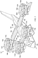
FIG. 1 is a perspective view of an aircraft oriented in a helicopter mode according to aspects of the disclosure; -
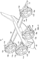
FIG. 2 is a perspective view of an aircraft oriented in an airplane mode according to aspects of the disclosure; -
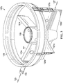
FIG. 3 is a perspective view of a ducted fan assembly according to aspects of the disclosure; -
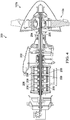
FIG. 4 is a sectioned view of a drivetrain according to aspects of the disclosure; and -
FIG. 5 is a sectioned view of a gearbox according to aspects of the disclosure. - Various aspects will now be described more fully with reference to the accompanying drawings. The disclosure may, however, be embodied in many different forms and should not be construed as limited to the aspects set forth herein.
- Referring now to
FIGS. 1 and2 , perspective views of arotorcraft 101 operating in helicopter and airplane modes, respectively, are shown according to aspects of the disclosure. Rotorcraft 101 is generally configured as a vertical takeoff and landing (VTOL) aircraft, more specifically a tiltrotor, that is operable in an airplane mode associated with forward flight and a helicopter mode associated with vertical takeoff from and landing to a landing zone. Rotorcraft 101 comprises afuselage 103 comprising a cockpit and/or passenger compartment,wings 105 extending from thefuselage 103, a pair ofducted fan assemblies fuselage 103, a pair of ducted fan assemblies107c, 107d carried by, supported by, and/or otherwise coupled towings 105.Ducted fan assemblies 107a-107d are arranged aboutfuselage 103 to be generally coplanar whenrotorcraft 101 is in helicopter and airplane modes. In other aspects, ductedfan assemblies fan assemblies fan assemblies 107a-107d may be ductless (e.g., comprising a fan or rotor without a duct). - Each ducted
fan assembly spindle 113 extending at least partially throughfuselage 103 and coupled to the pair of ductedfan assemblies fuselage 103 by at least one actuator (e.g. electric, electro-mechanical, magnetic, and/or hydraulic) in order to transitionrotorcraft 101 between the airplane mode and the helicopter mode. Each ductedfan assembly 107a-107d comprises aduct 108a-108d, respectively, with eachduct 108a-108d having a plurality of structural supports and/orstruts 110a-110d. In some aspects, outer surfaces of the ducts 108 may be shaped to provide optimal and/or preferred flight characteristics in at least one of the airplane mode and the helicopter mode. -
Ducted fan assemblies fan fans fan fan Fans FIG. 1 , eachfan fan - Each
wing 105 carries a single ducted fan assembly of the pair of ductedfan assemblies fan assemblies wings 105 and is coupled to the pair of ductedfan assemblies fuselage 103 by at least one actuator (e.g. electric, electro-mechanical, magnetic, and/or hydraulic) in order to transitionrotorcraft 101 between the airplane mode and the helicopter mode. The pair of ductedfan assemblies fan assemblies own duct struts fans fan assemblies ducted fan assemblies fuselage 103. Although ductedfan assemblies 107a-107d are described as includingfans 112a-112d, respectively, it will be appreciated that the ducted fan assemblies could include propellers, rotors, and the like. - Rotorcraft 101 is controlled via
flight control system 130.Flight control system 130 includesflight control computer 140 that connected to and in communication withpropulsion system 150.Propulsion system 150 is controlled byflight control computer 140 and includes components that assist with the flight of rotorcraft 101.Propulsion system 150 may generally include a hybrid electrical system, a hybrid hydraulic system and/or combinations thereof.Flight control computer 140 is configured to selectively control the components ofpropulsion system 150 to operate rotorcraft 101.Flight control system 130 may include flight control input hardware (e.g. flight controls) configured to receive inputs and/or commands from a pilot to control operation of therotorcraft 101 and/or a plurality of sensors and/or gauges configured to provide feedback regarding operational characteristics ofrotorcraft 101 to theflight control computer 140. Additionally,flight control computer 140 may be configured to selectively control the operation, orientation, rotation, position, and/or rotational speed of the pairs of ductedfan assemblies flight control system 130 may comprise fly-by-wire architecture for controllingrotorcraft 101. Additionally, in some aspects,flight control system 130 may be capable of optionally-piloted operation. Furthermore, in some aspects,flight control system 130 may comprise collective pitch control for adjusting the pitch of rotor blades 124 and rotational speed control for individually adjusting a rotational speed of rotor systems 122 of each of the ductedfan assemblies 107a-107d, without the need for cyclic control for controlling operation ofrotorcraft 101. -
FIG. 3 illustrates ductedfan assembly 107a according to aspects of the disclosure.Ducted fan assembly 107a will be discussed with the understanding that the discussion thereof applies to ductedfan assemblies 107b-107d.Ducted fan assembly 107a is depicted inFIG. 3 withoutfan 112a and includes acentral housing 119 that is configured to support and house components such as a rotor, a gearbox, and/or other components.Ducted fan assembly 107a further includes a plurality ofstators 121 that extend outward fromhousing 119. In this embodiment,ducted fan assembly 107a includes fourstators 121 that extend radially outward fromhousing 119. More specifically,ducted fan assembly 107a has two primary stators that include an inboardprimary stator 121a and an outboardprimary stator 121b. Inboardprimary stator 121a is configured to be coupled to a corresponding spindle, such asspindle 113.Ducted fan assembly 107a is rotatable about aspindle axis 123 that is defined byspindle 113.Ducted fan assembly 107a includes twosecondary stators 121c. Primary inboard andoutboard stators ducted fan assembly 107a back tofuselage 103 than aresecondary stators 121c. Inboardprimary stator 121a and outboardprimary stator 121b are longitudinally aligned relative to each other on opposed sides ofhousing 119 andsecondary stators 121c are longitudinally aligned relative to each other on opposed sides ofhousing 119 and aligned perpendicularly to inboardprimary stator 121a and outboardprimary stator 121b. In this regard,stators 121 are equally spaced abouthousing 119. It should be appreciated that ducted fan assembly 107 may be alternatively configured with more orfewer stators 121. It should further be appreciated thatducted fan assembly 107a may be alternatively configured with different spacing ofstators 121 abouthousing 119. -
Ducted fan assembly 107a further includes aninboard control vane 125a and anoutboard control vane 125b, which are pivotally attached to inboardprimary stator 121a and outboardprimary stator 121b, respectively.Inboard control vane 125a andoutboard control vane 125b are pivotable about avane axis 127 that extends parallel tospindle axis 123. In this embodiment,inboard control vane 125a andoutboard control vane 125b are configured to rotate together to facilitate yaw control, changes of direction, turning, etc. during flight ofrotorcraft 101. It should be appreciated, however, thatinboard control vane 125a andoutboard control vane 125b may alternatively be configured to rotate independently from one another. It should further be appreciated thatducted fan assembly 107a is not limited to the illustrated configuration ofinboard control vane 125a andoutboard control vane 125b. For example, ducted fan assembly 107 may alternatively be configured with more or fewer control vanes, such as a single control vane that defines a continuous control surface.Ducted fan assembly 107a may include one or more sections ofskin 129 that form an aerodynamic outer covering ofducted fan assembly 107a, and that define an opening that extends throughducted fan assembly 107a. As shown,housing 119 is located primarily aft of the opening. -
FIGS. 4 and5 are sectioned views of a ducted fan assembly according to aspects of the disclosure.FIGS. 4 and5 are discussed relative toducted fan assembly 107a with the understanding that the discussion thereof applies to ductedfan assemblies 107b-107d. InFIGS. 4 and5 ,duct 108a andcentral housing 119 are hidden from view for illustrative purposes.Ducted fan assembly 107a includes adrivetrain 200 that is housed incentral housing 119.Drivetrain 200 includes agearbox 202, amast 204, aninput shaft 206, and a plurality ofelectric motors 208. In the aspect illustrated inFIG. 4 ,drivetrain 200 includes a push/pull tube 205 that extends throughmast 204 andinput shaft 206. Push/pull tube 205 is coupled tofan 112a such that axial movement of push/pull tube 205 causes a pitch of the blades offan 112a to change. It will be appreciated by those of skill in the art thatmast 204 andinput shaft 206 can accommodate other components such as wiring and the like. -
Gearbox 202 includes anoil sump 210 with a chip detector/screen 212 positioned therein to remove debris from lubricant that circulates throughoutgearbox 202.Gearbox 202 also includes a planetary gear set 214 that is coupled betweeninput shaft 206 andmast 204. In the aspect ofFIG. 4 ,mast 204 is coupled directly to planetary gear set 214. In the aspect ofFIG. 5 ,mast 204 is coupled to planetary gear set 214 via a few intermediary couplers. The aspects ofFIGS. 4 and5 are meant to be illustrative. Planetary gear set 214 is used to reduce the speed ofinput shaft 206 to increase the torque supplied tomast 204. For example, planetary gear set 214 is configured with a gear ratio that reduces the speed ofmast 204 relative to inputshaft 206 between about 1:3 and 1:5.Fan 112a is secured tomast 204, and the torque supplied tomast 204 rotatesfan 112a to generate thrust.Input shaft 206 also drives anoil pump 216 that circulates lubricant (e.g., oil) throughoutgearbox 202. An additional benefit to the incorporation of planetary gear set 214 is thatinput shaft 206 andmast 204 are coaxially aligned, which minimizes the packaging size ofdrivetrain 200. In other aspects,input shaft 206 andmast 204 may be coupled through an arrangement other than planetary gear set 214. For example,input shaft 206 andmast 204 may be coupled via beveled gears and the like. - Each
electric motor 208 of the plurality ofelectric motors 208 is a relatively small and compact motor that is sometimes referred to as an axial flux, disc, or "pancake" motor.FIG. 4 illustrates threeelectric motors 208 arranged oninput shaft 206. In other aspects,drivetrain 200 may include as few as oneelectric motor 208, twoelectric motors 208, or more than threeelectric motors 208. Including more than oneelectric motor 208 is beneficial as it provides redundancy for safety. Eachelectric motor 208 is mounted to inputshaft 206 via asprag clutch 209. A sprag clutch transmits torque when rotated in a first direction and freewheels/overruns and does not transmit torque when rotated in an opposite direction. In other words, eachsprag clutch 209 allows its respectiveelectric motor 208 to transmit torque to inputshaft 206 when rotating in a first direction or alternatively to operate in an overrun or freewheel mode when rotating in second direction. In some aspects, eachsprag clutch 209 is a packed-grease sprag clutch that does not require a lubrication system to circulate a lubricant (e.g., oil or grease) to and from eachsprag clutch 209. Packed-grease sprag clutches are sealed units that do not require external lubrication. Using packed-grease style sprag clutches helps reduce the number of components that need to be packaged as a part ofdrivetrain 200 as no lubrication lines etc. are required to lubricate the sprag clutches. In some aspects, eachsprag clutch 209 is fluidly coupled to a lubrication system that provides lubricant (e.g., oil or grease) to eachsprag clutch 209. - In some aspects, each
electric motor 208 of the plurality ofelectric motors 208 may simultaneously operate to provide torque to inputshaft 206. In the event of a failure of oneelectric motor 208 of the plurality ofelectric motors 208, the failedelectric motor 208 is allowed to freewheel oninput shaft 206 by itssprag clutch 209 while the remainingelectric motors 208 continue to provide torque to inputshaft 206. In other aspects, only a singleelectric motor 208 of the plurality ofelectric motors 208 may be operated to provide torque to inputshaft 206 while the remainingelectric motors 208 of the plurality ofelectric motors 208 are permitted to freewheel by theirrespective sprag clutches 209. In the event of a failure of the first electric motor 208 (or if additional torque is needed), one or both of the remainingelectric motors 208 may be operated to provide torque to inputshaft 206. - Depending on the aspect, certain acts, events, or functions of any of the algorithms, methods, or processes described herein can be performed in a different sequence, can be added, merged, or left out altogether (e.g., not all described acts or events are necessary for the practice of the algorithms, methods, or processes). Moreover, in certain aspects, acts or events can be performed concurrently, e.g., through multi-threaded processing, interrupt processing, or multiple processors or processor cores or on other parallel architectures, rather than sequentially. Although certain computer-implemented tasks are described as being performed by a particular entity, other aspects are possible in which these tasks are performed by a different entity.
- Conditional language used herein, such as, among others, "can," "might," "may," "e.g.," and the like, unless specifically stated otherwise, or otherwise understood within the context as used, is generally intended to convey that certain aspects include, while other aspects do not include, certain features, elements and/or states. Thus, such conditional language is not generally intended to imply that features, elements and/or states are in any way required for one or more aspects or that one or more aspects necessarily include logic for deciding, with or without author input or prompting, whether these features, elements and/or states are included or are to be performed in any particular aspect.
- The term "substantially" is defined as largely but not necessarily wholly what is specified (and includes what is specified; e.g., substantially 90 degrees includes 90 degrees and substantially parallel includes parallel), as understood by a person of ordinary skill in the art. In any disclosed aspect, the terms "substantially," "approximately," "generally," "generally in the range of," and "about" may be substituted with "within [a percentage] of' what is specified, as understood by a person of ordinary skill in the art. For example, within 1%, 2%, 3%, 5%, and 10% of what is specified herein.
- While the above detailed description has shown, described, and pointed out novel features as applied to various aspects, it will be understood that various omissions, substitutions, and changes in the form and details of the devices or algorithms illustrated can be made without departing from the spirit of the disclosure. As will be recognized, the processes described herein can be embodied within a form that does not provide all of the features and benefits set forth herein, as some features can be used or practiced separately from others. The scope of protection is defined by the appended claims rather than by the foregoing description. All changes which come within the meaning and range of equivalency of the claims are to be embraced within their scope.
Claims (11)
- A drivetrain (200) for an aircraft, the drivetrain (200) comprising:an input shaft (206);a first electric motor (208) coupled to the input shaft (206) via a first sprag clutch (209);a planetary gear set (214) coupled to the input shaft (206); anda mast (204) coupled to the planetary gear set (214),wherein the input shaft (206) and the mast (204) are coaxially aligned.
- The drivetrain (200) of claim 1, further comprising a second electric motor (208) coupled to the input shaft (206) via a second sprag clutch (209).
- The drivetrain (200) of claim 1 or claim 2, wherein the planetary gear set (214) comprises a gear ratio that reduces a rotational speed of the mast (204) relative to the input shaft (206).
- The drivetrain (200) of any one of claims 1 to 3, wherein the first sprag clutch (209) is a packed-grease sprag clutch.
- A drivetrain (200) for an aircraft, the drivetrain (200) comprising:a gearbox (214) having an input shaft (206) and a mast (204) coaxially aligned with the input shaft (206); anda plurality of electric motors (208) coupled to the input shaft (206),wherein each electric motor of the plurality of electric motors (208) is coupled to the input shaft (206) via a sprag clutch (209).
- The drivetrain (200) of claim 5, wherein the input shaft (206) is coupled to the mast (204) via a planetary gear set (214).
- The drivetrain (200) of claim 6, wherein the planetary gear set (214) comprises a gear ratio that reduces a rotational speed of the mast (204) relative to the input shaft (206).
- The drivetrain (200) of any one of claims 5 to 7, wherein each sprag clutch (209) is a packed-grease sprag clutch.
- A rotorcraft (101) comprising:
a plurality of fan assemblies (107a-d), each fan assembly of the plurality of fan assemblies comprising a drivetrain (200) according to any one of claims 5 to 8. - The rotorcraft (101) of claim 9, wherein one or more of the plurality of fan assemblies (107a-d) are ducted fan assemblies.
- The rotorcraft (101) of claim 9 or claim 10, wherein the rotorcraft is a tiltrotor aircraft and the plurality of fan assemblies (107a-d) rotate between an airplane mode and a helicopter mode.
Applications Claiming Priority (1)
| Application Number | Priority Date | Filing Date | Title |
|---|---|---|---|
| US16/889,458 US11731779B2 (en) | 2020-06-01 | 2020-06-01 | Drivetrain for an aircraft including gearbox with coaxial input and output shafts |
Publications (2)
| Publication Number | Publication Date |
|---|---|
| EP3919376A1 true EP3919376A1 (en) | 2021-12-08 |
| EP3919376B1 EP3919376B1 (en) | 2023-01-18 |
Family
ID=74859274
Family Applications (1)
| Application Number | Title | Priority Date | Filing Date |
|---|---|---|---|
| EP21160912.8A Active EP3919376B1 (en) | 2020-06-01 | 2021-03-05 | Gearbox with coaxial input and output shafts |
Country Status (2)
| Country | Link |
|---|---|
| US (1) | US11731779B2 (en) |
| EP (1) | EP3919376B1 (en) |
Cited By (7)
| Publication number | Priority date | Publication date | Assignee | Title |
|---|---|---|---|---|
| US11718397B2 (en) | 2021-05-19 | 2023-08-08 | Textron Innovations Inc. | Electric tiltrotor aircraft |
| US11787551B1 (en) | 2022-10-06 | 2023-10-17 | Archer Aviation, Inc. | Vertical takeoff and landing aircraft electric engine configuration |
| FR3141675A1 (en) * | 2023-01-30 | 2024-05-10 | Airbus (S.A.S.) | Electric propulsion assembly comprising at least one electric motor having a tubular motor shaft, aircraft comprising at least one such propulsion assembly |
| EP4474289A1 (en) * | 2023-06-09 | 2024-12-11 | Pratt & Whitney Canada Corp. | Electric motor propulsion system for an aircraft |
| US12227300B2 (en) | 2022-10-06 | 2025-02-18 | Archer Aviation Inc. | Systems and methods for oil maintenance in gearboxes for eVTOL aircraft |
| US12234021B2 (en) | 2022-10-06 | 2025-02-25 | Archer Aviation Inc. | Systems and methods for improved gearboxes for evtol aircraft |
| US12649582B2 (en) | 2024-08-23 | 2026-06-09 | Archer Aviation Inc. | Systems and methods for oil maintenance and distribution in electric engines for evtol aircraft |
Families Citing this family (6)
| Publication number | Priority date | Publication date | Assignee | Title |
|---|---|---|---|---|
| EP4209414A1 (en) * | 2022-01-05 | 2023-07-12 | Zuri.com SE | Vertical takeoff and landing aircraft |
| FR3137894A1 (en) * | 2022-07-13 | 2024-01-19 | Airbus (S.A.S.) | Electric propulsion assembly comprising at least one electric motor positioned at the front of a transmission system, aircraft comprising at least one such propulsion assembly |
| US12337956B2 (en) * | 2023-02-22 | 2025-06-24 | Textron Innovations Inc. | System and method for monitoring clutch wear |
| FR3156836A1 (en) * | 2023-12-18 | 2025-06-20 | Safran Transmission Systems | MECHANICAL REDUCER FOR AN AIRCRAFT TURBOMACHINE |
| IT202400003511A1 (en) * | 2024-02-20 | 2025-08-20 | Umbragroup S P A | ELECTROMECHANICAL UNIT FOR VARIABLE PITCH PROPELLER |
| CA3284048A1 (en) * | 2024-08-26 | 2026-03-01 | Pratt & Whitney Canada Corp. | Clutched electric powerplant for aircraft propulsion system |
Citations (6)
| Publication number | Priority date | Publication date | Assignee | Title |
|---|---|---|---|---|
| CA699150A (en) * | 1964-12-01 | B. Candela Giovan | Sprag clutch and energizing means therefor | |
| CA2350495A1 (en) * | 1999-10-04 | 2001-04-12 | Masaru Morii | Automatic transmission for vehicles |
| US20090022608A1 (en) * | 2006-02-23 | 2009-01-22 | Zf Friedrichshafen Ag | Drive device for the oil pump of a motor vehicle transmission |
| US20100127119A1 (en) * | 2008-03-06 | 2010-05-27 | Karem Aircraft, Inc. | Rotorcraft engine and rotor speed synchronization |
| EP3333073A1 (en) * | 2016-12-11 | 2018-06-13 | Bell Helicopter Textron Inc. | Drivetrain subassembly having an integrated sprag clutch race and gear shaft member |
| CA3101225A1 (en) * | 2018-06-25 | 2020-01-02 | Kopter Group Ag | Rotorcraft having an electric drive for driving a main and/or tail rotor of the rotorcraft |
Family Cites Families (20)
| Publication number | Priority date | Publication date | Assignee | Title |
|---|---|---|---|---|
| US2984306A (en) | 1958-05-08 | 1961-05-16 | United Aircraft Corp | Helicopter rotor head and its controls |
| US3686978A (en) | 1971-04-09 | 1972-08-29 | Fairfied Mfg Co Inc | Plantetary reduction wheel hub |
| US4040312A (en) | 1974-10-29 | 1977-08-09 | Eaton Corporation | Planetary reduction drive unit |
| US5281094A (en) * | 1991-05-13 | 1994-01-25 | Alliedsignal Inc | Electromechanical apparatus for varying blade of variable-pitch fan blades |
| JP2001027261A (en) * | 1999-07-12 | 2001-01-30 | Nsk Warner Kk | One-way clutch assembly |
| DE10314234B3 (en) * | 2003-03-29 | 2004-10-28 | Aurator Treuhandgesellschaft Mbh | Four-wave power split transmission |
| DE102005034340B4 (en) | 2005-07-22 | 2013-05-16 | PS Automation GmbH Gesellschaft für Antriebstechnik | Planetary gear and actuator for valves with a planetary gear |
| US8720814B2 (en) * | 2005-10-18 | 2014-05-13 | Frick A. Smith | Aircraft with freewheeling engine |
| WO2010123601A1 (en) * | 2009-01-27 | 2010-10-28 | Kuhn Ira F Jr | Purebred and hybrid electric vtol tilt rotor aircraft |
| NO330820B1 (en) * | 2009-12-24 | 2011-07-25 | Prox Dynamics As | Rotor mechanism for helicopters |
| JP5748801B2 (en) | 2013-06-21 | 2015-07-15 | ジヤトコ株式会社 | Seal structure in automatic transmission |
| US9834303B2 (en) | 2013-08-14 | 2017-12-05 | Bell Helicopter Textron Inc. | Method and apparatus of connecting a fixed drive system to a rotating drive system for a tiltrotor aircraft |
| IL233942B (en) * | 2014-08-04 | 2020-01-30 | Israel Aerospace Ind Ltd | Assembly of the drive system |
| US10144507B2 (en) * | 2014-08-28 | 2018-12-04 | Pascal Chretien | Electromagnetic distributed direct drive for aircraft |
| CN104882998B (en) | 2015-06-03 | 2017-07-11 | 江苏胜开尓工业技术有限公司 | A kind of magnetic sealing device for big torque magnetic stirring apparatus |
| NO342415B1 (en) * | 2016-08-31 | 2018-05-22 | FLIR Unmanned Aerial Systems AS | Controlling blade pitch by a plurality of electric motors |
| US11008113B2 (en) | 2017-07-23 | 2021-05-18 | Textron Innovations Inc. | Clutch with synchronizer and locking mechanism |
| TWI648491B (en) | 2017-11-21 | 2019-01-21 | 摩特動力工業股份有限公司 | Coaxial electric power stepless transmission |
| US11053019B2 (en) * | 2018-04-19 | 2021-07-06 | The Boeing Company | Hybrid propulsion engines for aircraft |
| US11060593B2 (en) * | 2018-10-19 | 2021-07-13 | Hamilton Sundstrand Corporation | Jam-tolerant electric rotary actuator |
-
2020
- 2020-06-01 US US16/889,458 patent/US11731779B2/en active Active
-
2021
- 2021-03-05 EP EP21160912.8A patent/EP3919376B1/en active Active
Patent Citations (6)
| Publication number | Priority date | Publication date | Assignee | Title |
|---|---|---|---|---|
| CA699150A (en) * | 1964-12-01 | B. Candela Giovan | Sprag clutch and energizing means therefor | |
| CA2350495A1 (en) * | 1999-10-04 | 2001-04-12 | Masaru Morii | Automatic transmission for vehicles |
| US20090022608A1 (en) * | 2006-02-23 | 2009-01-22 | Zf Friedrichshafen Ag | Drive device for the oil pump of a motor vehicle transmission |
| US20100127119A1 (en) * | 2008-03-06 | 2010-05-27 | Karem Aircraft, Inc. | Rotorcraft engine and rotor speed synchronization |
| EP3333073A1 (en) * | 2016-12-11 | 2018-06-13 | Bell Helicopter Textron Inc. | Drivetrain subassembly having an integrated sprag clutch race and gear shaft member |
| CA3101225A1 (en) * | 2018-06-25 | 2020-01-02 | Kopter Group Ag | Rotorcraft having an electric drive for driving a main and/or tail rotor of the rotorcraft |
Cited By (24)
| Publication number | Priority date | Publication date | Assignee | Title |
|---|---|---|---|---|
| US11718397B2 (en) | 2021-05-19 | 2023-08-08 | Textron Innovations Inc. | Electric tiltrotor aircraft |
| EP4091940B1 (en) * | 2021-05-19 | 2023-09-06 | Textron Innovations Inc. | Electric tiltrotor aircraft |
| US12208908B2 (en) | 2022-10-06 | 2025-01-28 | Archer Aviation Inc. | Systems and methods for oil management in gearboxes for eVTOL aircraft |
| US12227300B2 (en) | 2022-10-06 | 2025-02-18 | Archer Aviation Inc. | Systems and methods for oil maintenance in gearboxes for eVTOL aircraft |
| US11912424B1 (en) | 2022-10-06 | 2024-02-27 | Archer Aviation Inc. | Systems and methods for improved gearboxes for eVTOL aircraft |
| US11958621B1 (en) | 2022-10-06 | 2024-04-16 | Archer Aviation, Inc. | Systems and methods for, and components of, gearboxes for eVTOL aircraft |
| US11975853B2 (en) | 2022-10-06 | 2024-05-07 | Archer Aviation, Inc. | Systems for cooling an electrical engine for eVTOL aircraft using an end bell assembly connected to a thermal plate |
| US12583593B2 (en) | 2022-10-06 | 2026-03-24 | Archer Aviation Inc. | Systems and methods for oil maintenance in gearboxes for eVTOL aircraft |
| US12024304B2 (en) | 2022-10-06 | 2024-07-02 | Archer Aviation, Inc. | Systems and methods for oil maintenance in gearboxes for eVTOL aircraft |
| US12030656B1 (en) | 2022-10-06 | 2024-07-09 | Archer Aviation, Inc. | Systems and methods for oil management in gearboxes for evtol aircraft |
| US12129040B2 (en) | 2022-10-06 | 2024-10-29 | Archer Aviation Inc. | Systems and methods for oil management in gearboxes for eVTOL aircraft |
| US12234021B2 (en) | 2022-10-06 | 2025-02-25 | Archer Aviation Inc. | Systems and methods for improved gearboxes for evtol aircraft |
| US11820523B1 (en) | 2022-10-06 | 2023-11-21 | Archer Aviation, Inc. | Systems and methods for, and components of, gearboxes for eVTOL aircraft |
| US11787551B1 (en) | 2022-10-06 | 2023-10-17 | Archer Aviation, Inc. | Vertical takeoff and landing aircraft electric engine configuration |
| US12486022B2 (en) | 2022-10-06 | 2025-12-02 | Archer Aviation Inc. | Systems and methods for oil management in gearboxes for EVTOL aircraft |
| US12286234B2 (en) | 2022-10-06 | 2025-04-29 | Archer Aviation Inc. | Aircraft electric propulsion system with overlapping shafts for gearbox oil distribution |
| US12312091B2 (en) | 2022-10-06 | 2025-05-27 | Archer Aviation Inc. | Systems and methods for improved gearboxes for evtol aircraft |
| US12384547B2 (en) | 2022-10-06 | 2025-08-12 | Archer Aviation Inc. | Systems and methods for improved gearboxes for EVTOL aircraft |
| US12473074B2 (en) | 2022-10-06 | 2025-11-18 | Archer Aviation Inc. | Aircraft propulsion system including pump gear driven by planetary gearbox assembly |
| US12486021B2 (en) | 2022-10-06 | 2025-12-02 | Archer Aviation Inc. | Electric propulsion system for an aircraft including a motor located between a gearbox assembly and a propeller |
| FR3141675A1 (en) * | 2023-01-30 | 2024-05-10 | Airbus (S.A.S.) | Electric propulsion assembly comprising at least one electric motor having a tubular motor shaft, aircraft comprising at least one such propulsion assembly |
| EP4474289A1 (en) * | 2023-06-09 | 2024-12-11 | Pratt & Whitney Canada Corp. | Electric motor propulsion system for an aircraft |
| EP4768394A3 (en) * | 2023-06-09 | 2026-08-12 | Pratt & Whitney Canada Corp. | Electric motor propulsion system for an aircraft |
| US12649582B2 (en) | 2024-08-23 | 2026-06-09 | Archer Aviation Inc. | Systems and methods for oil maintenance and distribution in electric engines for evtol aircraft |
Also Published As
| Publication number | Publication date |
|---|---|
| US20210371120A1 (en) | 2021-12-02 |
| EP3919376B1 (en) | 2023-01-18 |
| US11731779B2 (en) | 2023-08-22 |
Similar Documents
| Publication | Publication Date | Title |
|---|---|---|
| US11731779B2 (en) | Drivetrain for an aircraft including gearbox with coaxial input and output shafts | |
| US11970283B2 (en) | Dual motor input with overrunning clutch | |
| US11608167B2 (en) | Fail-operational VTOL aircraft | |
| EP3564122B1 (en) | Hybrid tiltrotor drive system | |
| EP3495260B1 (en) | Dual rotor propulsion systems for tiltrotor aircraft | |
| EP3875375B1 (en) | Rotor system with a swashplate and an electric drive system as a single integrated unit. | |
| CN109665094B (en) | Multi-rotor aircraft with fuselage and at least one wing | |
| EP3930158A1 (en) | Segmented input shaft for electric motor stack and gearbox unit | |
| US11465738B2 (en) | Fail-operational VTOL aircraft | |
| US11554866B2 (en) | Line replaceable centerbody assemblies for ducted propulsion | |
| EP3929089B1 (en) | Electric motor stack with integral one-piece gearbox input shaft | |
| EP3428065A1 (en) | Variable-speed drive system for tiltrotor with fixed engine and rotating proprotor | |
| EP3876400A1 (en) | Electric drive system line replaceable unit with integrated thermal cooling | |
| US12434823B2 (en) | Electric tiltrotor aircraft with fixed motors | |
| WO2008118131A1 (en) | Fail-operational multiple lifting-rotor aircraft | |
| EP3933228B1 (en) | Sealed coaxial input and output shafts | |
| KR102211475B1 (en) | Aerial vehicle with distributed electric power tilt prop | |
| US11634233B2 (en) | Distributed battery bank for ducted-rotor aircraft | |
| US20200283139A1 (en) | Hybrid rotor propulsion for rotor aircraft | |
| US11794886B2 (en) | Hybrid rotorcraft having at least one pusher or puller propeller, and an associated piloting method | |
| CN120239672A (en) | Electric coaxial rotor aircraft | |
| WO2014062091A1 (en) | Vertical take-off and landing craft | |
| WO2005044662A1 (en) | Aircraft power assembly and aircraft provided with such an assembly |
Legal Events
| Date | Code | Title | Description |
|---|---|---|---|
| STAA | Information on the status of an ep patent application or granted ep patent |
Free format text: STATUS: EXAMINATION IS IN PROGRESS |
|
| PUAI | Public reference made under article 153(3) epc to a published international application that has entered the european phase |
Free format text: ORIGINAL CODE: 0009012 |
|
| 17P | Request for examination filed |
Effective date: 20210305 |
|
| AK | Designated contracting states |
Kind code of ref document: A1 Designated state(s): AL AT BE BG CH CY CZ DE DK EE ES FI FR GB GR HR HU IE IS IT LI LT LU LV MC MK MT NL NO PL PT RO RS SE SI SK SM TR |
|
| B565 | Issuance of search results under rule 164(2) epc |
Effective date: 20210811 |
|
| GRAP | Despatch of communication of intention to grant a patent |
Free format text: ORIGINAL CODE: EPIDOSNIGR1 |
|
| STAA | Information on the status of an ep patent application or granted ep patent |
Free format text: STATUS: GRANT OF PATENT IS INTENDED |
|
| RIC1 | Information provided on ipc code assigned before grant |
Ipc: F16D 41/069 20060101ALN20220928BHEP Ipc: F16H 57/08 20060101ALI20220928BHEP Ipc: F16H 57/04 20100101ALI20220928BHEP Ipc: F16H 57/00 20120101ALI20220928BHEP Ipc: B64C 29/00 20060101ALI20220928BHEP Ipc: B64C 27/58 20060101ALI20220928BHEP Ipc: B64C 27/20 20060101ALI20220928BHEP Ipc: B64C 27/12 20060101AFI20220928BHEP |
|
| RIC1 | Information provided on ipc code assigned before grant |
Ipc: F16D 41/069 20060101ALN20221004BHEP Ipc: F16H 57/08 20060101ALI20221004BHEP Ipc: F16H 57/04 20100101ALI20221004BHEP Ipc: F16H 57/00 20120101ALI20221004BHEP Ipc: B64C 29/00 20060101ALI20221004BHEP Ipc: B64C 27/58 20060101ALI20221004BHEP Ipc: B64C 27/20 20060101ALI20221004BHEP Ipc: B64C 27/12 20060101AFI20221004BHEP |
|
| INTG | Intention to grant announced |
Effective date: 20221020 |
|
| GRAS | Grant fee paid |
Free format text: ORIGINAL CODE: EPIDOSNIGR3 |
|
| GRAA | (expected) grant |
Free format text: ORIGINAL CODE: 0009210 |
|
| STAA | Information on the status of an ep patent application or granted ep patent |
Free format text: STATUS: THE PATENT HAS BEEN GRANTED |
|
| RAP1 | Party data changed (applicant data changed or rights of an application transferred) |
Owner name: TEXTRON INNOVATIONS INC. |
|
| AK | Designated contracting states |
Kind code of ref document: B1 Designated state(s): AL AT BE BG CH CY CZ DE DK EE ES FI FR GB GR HR HU IE IS IT LI LT LU LV MC MK MT NL NO PL PT RO RS SE SI SK SM TR |
|
| REG | Reference to a national code |
Ref country code: GB Ref legal event code: FG4D |
|
| REG | Reference to a national code |
Ref country code: DE Ref legal event code: R096 Ref document number: 602021001237 Country of ref document: DE |
|
| REG | Reference to a national code |
Ref country code: CH Ref legal event code: EP |
|
| REG | Reference to a national code |
Ref country code: AT Ref legal event code: REF Ref document number: 1544555 Country of ref document: AT Kind code of ref document: T Effective date: 20230215 Ref country code: IE Ref legal event code: FG4D |
|
| REG | Reference to a national code |
Ref country code: LT Ref legal event code: MG9D |
|
| REG | Reference to a national code |
Ref country code: NL Ref legal event code: MP Effective date: 20230118 |
|
| REG | Reference to a national code |
Ref country code: AT Ref legal event code: MK05 Ref document number: 1544555 Country of ref document: AT Kind code of ref document: T Effective date: 20230118 |
|
| PG25 | Lapsed in a contracting state [announced via postgrant information from national office to epo] |
Ref country code: NL Free format text: LAPSE BECAUSE OF FAILURE TO SUBMIT A TRANSLATION OF THE DESCRIPTION OR TO PAY THE FEE WITHIN THE PRESCRIBED TIME-LIMIT Effective date: 20230118 |
|
| P01 | Opt-out of the competence of the unified patent court (upc) registered |
Effective date: 20230602 |
|
| PG25 | Lapsed in a contracting state [announced via postgrant information from national office to epo] |
Ref country code: RS Free format text: LAPSE BECAUSE OF FAILURE TO SUBMIT A TRANSLATION OF THE DESCRIPTION OR TO PAY THE FEE WITHIN THE PRESCRIBED TIME-LIMIT Effective date: 20230118 Ref country code: PT Free format text: LAPSE BECAUSE OF FAILURE TO SUBMIT A TRANSLATION OF THE DESCRIPTION OR TO PAY THE FEE WITHIN THE PRESCRIBED TIME-LIMIT Effective date: 20230518 Ref country code: NO Free format text: LAPSE BECAUSE OF FAILURE TO SUBMIT A TRANSLATION OF THE DESCRIPTION OR TO PAY THE FEE WITHIN THE PRESCRIBED TIME-LIMIT Effective date: 20230418 Ref country code: LV Free format text: LAPSE BECAUSE OF FAILURE TO SUBMIT A TRANSLATION OF THE DESCRIPTION OR TO PAY THE FEE WITHIN THE PRESCRIBED TIME-LIMIT Effective date: 20230118 Ref country code: LT Free format text: LAPSE BECAUSE OF FAILURE TO SUBMIT A TRANSLATION OF THE DESCRIPTION OR TO PAY THE FEE WITHIN THE PRESCRIBED TIME-LIMIT Effective date: 20230118 Ref country code: HR Free format text: LAPSE BECAUSE OF FAILURE TO SUBMIT A TRANSLATION OF THE DESCRIPTION OR TO PAY THE FEE WITHIN THE PRESCRIBED TIME-LIMIT Effective date: 20230118 Ref country code: ES Free format text: LAPSE BECAUSE OF FAILURE TO SUBMIT A TRANSLATION OF THE DESCRIPTION OR TO PAY THE FEE WITHIN THE PRESCRIBED TIME-LIMIT Effective date: 20230118 Ref country code: AT Free format text: LAPSE BECAUSE OF FAILURE TO SUBMIT A TRANSLATION OF THE DESCRIPTION OR TO PAY THE FEE WITHIN THE PRESCRIBED TIME-LIMIT Effective date: 20230118 |
|
| PG25 | Lapsed in a contracting state [announced via postgrant information from national office to epo] |
Ref country code: SE Free format text: LAPSE BECAUSE OF FAILURE TO SUBMIT A TRANSLATION OF THE DESCRIPTION OR TO PAY THE FEE WITHIN THE PRESCRIBED TIME-LIMIT Effective date: 20230118 Ref country code: PL Free format text: LAPSE BECAUSE OF FAILURE TO SUBMIT A TRANSLATION OF THE DESCRIPTION OR TO PAY THE FEE WITHIN THE PRESCRIBED TIME-LIMIT Effective date: 20230118 Ref country code: IS Free format text: LAPSE BECAUSE OF FAILURE TO SUBMIT A TRANSLATION OF THE DESCRIPTION OR TO PAY THE FEE WITHIN THE PRESCRIBED TIME-LIMIT Effective date: 20230518 Ref country code: GR Free format text: LAPSE BECAUSE OF FAILURE TO SUBMIT A TRANSLATION OF THE DESCRIPTION OR TO PAY THE FEE WITHIN THE PRESCRIBED TIME-LIMIT Effective date: 20230419 Ref country code: FI Free format text: LAPSE BECAUSE OF FAILURE TO SUBMIT A TRANSLATION OF THE DESCRIPTION OR TO PAY THE FEE WITHIN THE PRESCRIBED TIME-LIMIT Effective date: 20230118 |
|
| REG | Reference to a national code |
Ref country code: DE Ref legal event code: R097 Ref document number: 602021001237 Country of ref document: DE |
|
| PG25 | Lapsed in a contracting state [announced via postgrant information from national office to epo] |
Ref country code: SM Free format text: LAPSE BECAUSE OF FAILURE TO SUBMIT A TRANSLATION OF THE DESCRIPTION OR TO PAY THE FEE WITHIN THE PRESCRIBED TIME-LIMIT Effective date: 20230118 Ref country code: RO Free format text: LAPSE BECAUSE OF FAILURE TO SUBMIT A TRANSLATION OF THE DESCRIPTION OR TO PAY THE FEE WITHIN THE PRESCRIBED TIME-LIMIT Effective date: 20230118 Ref country code: MC Free format text: LAPSE BECAUSE OF FAILURE TO SUBMIT A TRANSLATION OF THE DESCRIPTION OR TO PAY THE FEE WITHIN THE PRESCRIBED TIME-LIMIT Effective date: 20230118 Ref country code: EE Free format text: LAPSE BECAUSE OF FAILURE TO SUBMIT A TRANSLATION OF THE DESCRIPTION OR TO PAY THE FEE WITHIN THE PRESCRIBED TIME-LIMIT Effective date: 20230118 Ref country code: DK Free format text: LAPSE BECAUSE OF FAILURE TO SUBMIT A TRANSLATION OF THE DESCRIPTION OR TO PAY THE FEE WITHIN THE PRESCRIBED TIME-LIMIT Effective date: 20230118 Ref country code: CZ Free format text: LAPSE BECAUSE OF FAILURE TO SUBMIT A TRANSLATION OF THE DESCRIPTION OR TO PAY THE FEE WITHIN THE PRESCRIBED TIME-LIMIT Effective date: 20230118 |
|
| PLBE | No opposition filed within time limit |
Free format text: ORIGINAL CODE: 0009261 |
|
| STAA | Information on the status of an ep patent application or granted ep patent |
Free format text: STATUS: NO OPPOSITION FILED WITHIN TIME LIMIT |
|
| PG25 | Lapsed in a contracting state [announced via postgrant information from national office to epo] |
Ref country code: SK Free format text: LAPSE BECAUSE OF FAILURE TO SUBMIT A TRANSLATION OF THE DESCRIPTION OR TO PAY THE FEE WITHIN THE PRESCRIBED TIME-LIMIT Effective date: 20230118 |
|
| REG | Reference to a national code |
Ref country code: BE Ref legal event code: MM Effective date: 20230331 |
|
| 26N | No opposition filed |
Effective date: 20231019 |
|
| PG25 | Lapsed in a contracting state [announced via postgrant information from national office to epo] |
Ref country code: LU Free format text: LAPSE BECAUSE OF NON-PAYMENT OF DUE FEES Effective date: 20230305 |
|
| REG | Reference to a national code |
Ref country code: IE Ref legal event code: MM4A |
|
| PG25 | Lapsed in a contracting state [announced via postgrant information from national office to epo] |
Ref country code: SI Free format text: LAPSE BECAUSE OF FAILURE TO SUBMIT A TRANSLATION OF THE DESCRIPTION OR TO PAY THE FEE WITHIN THE PRESCRIBED TIME-LIMIT Effective date: 20230118 Ref country code: IE Free format text: LAPSE BECAUSE OF NON-PAYMENT OF DUE FEES Effective date: 20230305 |
|
| PG25 | Lapsed in a contracting state [announced via postgrant information from national office to epo] |
Ref country code: BE Free format text: LAPSE BECAUSE OF NON-PAYMENT OF DUE FEES Effective date: 20230331 |
|
| REG | Reference to a national code |
Ref country code: CH Ref legal event code: PL |
|
| PG25 | Lapsed in a contracting state [announced via postgrant information from national office to epo] |
Ref country code: BG Free format text: LAPSE BECAUSE OF FAILURE TO SUBMIT A TRANSLATION OF THE DESCRIPTION OR TO PAY THE FEE WITHIN THE PRESCRIBED TIME-LIMIT Effective date: 20230118 |
|
| PG25 | Lapsed in a contracting state [announced via postgrant information from national office to epo] |
Ref country code: BG Free format text: LAPSE BECAUSE OF FAILURE TO SUBMIT A TRANSLATION OF THE DESCRIPTION OR TO PAY THE FEE WITHIN THE PRESCRIBED TIME-LIMIT Effective date: 20230118 |
|
| PG25 | Lapsed in a contracting state [announced via postgrant information from national office to epo] |
Ref country code: CH Free format text: LAPSE BECAUSE OF NON-PAYMENT OF DUE FEES Effective date: 20240331 |
|
| PG25 | Lapsed in a contracting state [announced via postgrant information from national office to epo] |
Ref country code: CY Free format text: LAPSE BECAUSE OF FAILURE TO SUBMIT A TRANSLATION OF THE DESCRIPTION OR TO PAY THE FEE WITHIN THE PRESCRIBED TIME-LIMIT; INVALID AB INITIO Effective date: 20210305 |
|
| PG25 | Lapsed in a contracting state [announced via postgrant information from national office to epo] |
Ref country code: HU Free format text: LAPSE BECAUSE OF FAILURE TO SUBMIT A TRANSLATION OF THE DESCRIPTION OR TO PAY THE FEE WITHIN THE PRESCRIBED TIME-LIMIT; INVALID AB INITIO Effective date: 20210305 |
|
| PG25 | Lapsed in a contracting state [announced via postgrant information from national office to epo] |
Ref country code: TR Free format text: LAPSE BECAUSE OF FAILURE TO SUBMIT A TRANSLATION OF THE DESCRIPTION OR TO PAY THE FEE WITHIN THE PRESCRIBED TIME-LIMIT Effective date: 20230118 |
|
| PGFP | Annual fee paid to national office [announced via postgrant information from national office to epo] |
Ref country code: GB Payment date: 20260327 Year of fee payment: 6 |
|
| PGFP | Annual fee paid to national office [announced via postgrant information from national office to epo] |
Ref country code: DE Payment date: 20260327 Year of fee payment: 6 |
|
| PGFP | Annual fee paid to national office [announced via postgrant information from national office to epo] |
Ref country code: IT Payment date: 20260319 Year of fee payment: 6 |
|
| PGFP | Annual fee paid to national office [announced via postgrant information from national office to epo] |
Ref country code: FR Payment date: 20260325 Year of fee payment: 6 |
|
| PG25 | Lapsed in a contracting state [announced via postgrant information from national office to epo] |
Ref country code: CH Free format text: THE PATENT HAS BEEN ANNULLED BY A DECISION OF A NATIONAL AUTHORITY Effective date: 20240331 |
|
| PG25 | Lapsed in a contracting state [announced via postgrant information from national office to epo] |
Ref country code: MT Free format text: LAPSE BECAUSE OF NON-PAYMENT OF DUE FEES Effective date: 20230305 |