EP3919372A1 - Single motor single actuator rotorcraft - Google Patents
Single motor single actuator rotorcraft Download PDFInfo
- Publication number
- EP3919372A1 EP3919372A1 EP21176695.1A EP21176695A EP3919372A1 EP 3919372 A1 EP3919372 A1 EP 3919372A1 EP 21176695 A EP21176695 A EP 21176695A EP 3919372 A1 EP3919372 A1 EP 3919372A1
- Authority
- EP
- European Patent Office
- Prior art keywords
- rotorcraft
- propulsion unit
- airframe
- propeller
- actuator
- Prior art date
- Legal status (The legal status is an assumption and is not a legal conclusion. Google has not performed a legal analysis and makes no representation as to the accuracy of the status listed.)
- Granted
Links
Images




Classifications
-
- B—PERFORMING OPERATIONS; TRANSPORTING
- B64—AIRCRAFT; AVIATION; COSMONAUTICS
- B64C—AEROPLANES; HELICOPTERS
- B64C13/00—Control systems or transmitting systems for actuating flying-control surfaces, lift-increasing flaps, air brakes, or spoilers
- B64C13/24—Transmitting means
-
- B—PERFORMING OPERATIONS; TRANSPORTING
- B64—AIRCRAFT; AVIATION; COSMONAUTICS
- B64C—AEROPLANES; HELICOPTERS
- B64C11/00—Propellers, e.g. of ducted type; Features common to propellers and rotors for rotorcraft
- B64C11/16—Blades
- B64C11/20—Constructional features
- B64C11/28—Collapsible or foldable blades
-
- B—PERFORMING OPERATIONS; TRANSPORTING
- B64—AIRCRAFT; AVIATION; COSMONAUTICS
- B64C—AEROPLANES; HELICOPTERS
- B64C11/00—Propellers, e.g. of ducted type; Features common to propellers and rotors for rotorcraft
- B64C11/46—Arrangements of, or constructional features peculiar to, multiple propellers
- B64C11/48—Units of two or more coaxial propellers
-
- B—PERFORMING OPERATIONS; TRANSPORTING
- B64—AIRCRAFT; AVIATION; COSMONAUTICS
- B64C—AEROPLANES; HELICOPTERS
- B64C27/00—Rotorcraft; Rotors peculiar thereto
- B64C27/02—Gyroplanes
- B64C27/021—Rotor or rotor head construction
- B64C27/022—Devices for folding or adjusting the blades
-
- B—PERFORMING OPERATIONS; TRANSPORTING
- B64—AIRCRAFT; AVIATION; COSMONAUTICS
- B64C—AEROPLANES; HELICOPTERS
- B64C27/00—Rotorcraft; Rotors peculiar thereto
- B64C27/02—Gyroplanes
- B64C27/021—Rotor or rotor head construction
- B64C27/024—Devices for shifting the rotor axis
-
- B—PERFORMING OPERATIONS; TRANSPORTING
- B64—AIRCRAFT; AVIATION; COSMONAUTICS
- B64C—AEROPLANES; HELICOPTERS
- B64C27/00—Rotorcraft; Rotors peculiar thereto
- B64C27/32—Rotors
- B64C27/37—Rotors having articulated joints
-
- B—PERFORMING OPERATIONS; TRANSPORTING
- B64—AIRCRAFT; AVIATION; COSMONAUTICS
- B64C—AEROPLANES; HELICOPTERS
- B64C27/00—Rotorcraft; Rotors peculiar thereto
- B64C27/32—Rotors
- B64C27/46—Blades
- B64C27/473—Constructional features
- B64C27/50—Blades foldable to facilitate stowage of aircraft
-
- B—PERFORMING OPERATIONS; TRANSPORTING
- B64—AIRCRAFT; AVIATION; COSMONAUTICS
- B64C—AEROPLANES; HELICOPTERS
- B64C27/00—Rotorcraft; Rotors peculiar thereto
- B64C27/52—Tilting of rotor bodily relative to fuselage
-
- B—PERFORMING OPERATIONS; TRANSPORTING
- B64—AIRCRAFT; AVIATION; COSMONAUTICS
- B64C—AEROPLANES; HELICOPTERS
- B64C27/00—Rotorcraft; Rotors peculiar thereto
- B64C27/82—Rotorcraft; Rotors peculiar thereto characterised by the provision of an auxiliary rotor or fluid-jet device for counter-balancing lifting rotor torque or changing direction of rotorcraft
-
- B—PERFORMING OPERATIONS; TRANSPORTING
- B64—AIRCRAFT; AVIATION; COSMONAUTICS
- B64U—UNMANNED AERIAL VEHICLES [UAV]; EQUIPMENT THEREFOR
- B64U30/00—Means for producing lift; Empennages; Arrangements thereof
- B64U30/20—Rotors; Rotor supports
- B64U30/24—Coaxial rotors
-
- B—PERFORMING OPERATIONS; TRANSPORTING
- B64—AIRCRAFT; AVIATION; COSMONAUTICS
- B64U—UNMANNED AERIAL VEHICLES [UAV]; EQUIPMENT THEREFOR
- B64U30/00—Means for producing lift; Empennages; Arrangements thereof
- B64U30/20—Rotors; Rotor supports
- B64U30/29—Constructional aspects of rotors or rotor supports; Arrangements thereof
- B64U30/293—Foldable or collapsible rotors or rotor supports
-
- B—PERFORMING OPERATIONS; TRANSPORTING
- B64—AIRCRAFT; AVIATION; COSMONAUTICS
- B64U—UNMANNED AERIAL VEHICLES [UAV]; EQUIPMENT THEREFOR
- B64U50/00—Propulsion; Power supply
- B64U50/10—Propulsion
- B64U50/19—Propulsion using electrically powered motors
-
- G—PHYSICS
- G05—CONTROLLING; REGULATING
- G05D—SYSTEMS FOR CONTROLLING OR REGULATING NON-ELECTRIC VARIABLES
- G05D1/00—Control of position, course, altitude or attitude of land, water, air or space vehicles, e.g. using automatic pilots
- G05D1/10—Simultaneous control of position or course in three dimensions
- G05D1/101—Simultaneous control of position or course in three dimensions specially adapted for aircraft
-
- B—PERFORMING OPERATIONS; TRANSPORTING
- B64—AIRCRAFT; AVIATION; COSMONAUTICS
- B64U—UNMANNED AERIAL VEHICLES [UAV]; EQUIPMENT THEREFOR
- B64U10/00—Type of UAV
- B64U10/10—Rotorcrafts
- B64U10/13—Flying platforms
-
- B—PERFORMING OPERATIONS; TRANSPORTING
- B64—AIRCRAFT; AVIATION; COSMONAUTICS
- B64U—UNMANNED AERIAL VEHICLES [UAV]; EQUIPMENT THEREFOR
- B64U2101/00—UAVs specially adapted for particular uses or applications
- B64U2101/30—UAVs specially adapted for particular uses or applications for imaging, photography or videography
- B64U2101/31—UAVs specially adapted for particular uses or applications for imaging, photography or videography for surveillance
-
- B—PERFORMING OPERATIONS; TRANSPORTING
- B64—AIRCRAFT; AVIATION; COSMONAUTICS
- B64U—UNMANNED AERIAL VEHICLES [UAV]; EQUIPMENT THEREFOR
- B64U2101/00—UAVs specially adapted for particular uses or applications
- B64U2101/60—UAVs specially adapted for particular uses or applications for transporting passengers; for transporting goods other than weapons
-
- B—PERFORMING OPERATIONS; TRANSPORTING
- B64—AIRCRAFT; AVIATION; COSMONAUTICS
- B64U—UNMANNED AERIAL VEHICLES [UAV]; EQUIPMENT THEREFOR
- B64U2201/00—UAVs characterised by their flight controls
- B64U2201/10—UAVs characterised by their flight controls autonomous, i.e. by navigating independently from ground or air stations, e.g. by using inertial navigation systems [INS]
Definitions
- UAVs Unmanned Aerial Vehicles
- applications for their use continues to evolve at a rapid pace.
- drones are used for aerial photography, to fill combat roles, by hobbyists, and are contemplated for use in the delivery of goods and services.
- known rotorcraft drones that are capable of hovering as well as forward flight typically have multiple rotors and can be prohibitively expensive and/or overly complicated to operate for use in certain roles.
- Unmanned rotorcraft having a single motor and a propulsion unit that is reoriented via a single actuator, along with methods for such rotorcraft to maintain a flight path, are disclosed herein.
- Such unmanned rotorcraft may be provided with collapsible blades that are adapted to deploy when flight is initiated.
- FIG. 1 is an oblique view of an unmanned rotorcraft 101.
- Rotorcraft 101 comprises an airframe 103, a plurality of main rotor blades 105 that are coupled to airframe 103 for rotation therewith, and a propulsion unit 107 having a propeller 109 that includes a plurality of propeller blades 111.
- airframe 103 has a substantially cylindrical shape that extends from a first end 113 to a second end 115.
- airframe 103 can be alternatively implemented with any other suitable geometry.
- Blades 105 are coupled to airframe 103 in fixed positions for rotation therewith about a rotor axis 117. As shown, blades 105 are coupled to airframe 103 at first end 113 thereof. Each blade 105 extends from a root 119 that is coupled to airframe 103 to a tip 121. In this embodiment, blades 105 are adapted to be collapsible relative to airframe 103. More specifically, root 119 of each blade 105 is pivotally coupled to airframe 103. Blades 105 are collapsible toward airframe 103 when rotorcraft 101 is not in flight, for example by folding blades 105 toward airframe 103 such that tips 121 move inward toward airframe 103 and toward second end 115 thereof.
- Rotorcraft 101 is configured such that blades 105 can be secured in respective collapsed positions relative to airframe 103 while rotorcraft 101 is not in flight, and such that blades 105 deploy from their respective collapsed positions when flight of rotorcraft 101 is initiated.
- rotorcraft 101 is adapted such that blades 105 deploy from their collapsed positions when flight of rotorcraft 101 is initiated and airframe 103 rotates about rotor axis 117.
- blades 105 are adapted to lock into respective deployed positions after flight of rotorcraft 101 is initiated.
- blades 105 are configured in accordance with desired flight characteristics of rotorcraft 101.
- desired flight characteristics of rotorcraft 101 For example, one or more physical characteristics of blades 105, such as respective dimensions, geometry, camber, and pitch thereof, can be configured based on an expected rotation rate of airframe 103, to impart desired lift and anti-torque forces to rotorcraft 101.
- propulsion unit 107 is located proximate to second end 115 of airframe 103.
- blades 105 and propulsion unit 107 are located at opposed ends of airframe 103.
- Propulsion unit 107 includes a motor (not shown) that causes blades 111 of propeller 109 to rotate about a propeller axis 123.
- rotation of propeller 109 imparts counter-rotation to airframe 103, thus causing blades 105 to rotate.
- rotation of blades 111 in a first direction 125 about propeller axis 123 causes blades 105 to rotate in an opposed second direction 127 about rotor axis 117.
- first direction 125 is not limited to the illustrated counterclockwise rotation.
- propulsion unit 107 can alternatively be adapted to cause blades 111 to rotate in second direction 127, which in turn would cause blades 105 to rotate in first direction 125.
- blades 111 are adapted to be at least partially collapsible relative to airframe 103. More specifically, each blade 111 has a fixed portion 129 that extends outward from a propeller shaft (not shown) of propulsion unit 107 and a collapsible portion 131 that is pivotable relative to airframe 103. Portions 131 of blades 111 are collapsible toward airframe 103 when rotorcraft 101 is not in flight, for example by folding the portions 131 toward airframe 103 such that tips 133 of blades 111 move inward toward airframe 103 and toward first end 113 thereof.
- Rotorcraft 101 is configured such that portions 131 of blades 111 can be secured in respective collapsed positions relative to airframe 103 while rotorcraft 101 is not in flight, and such that portions 131 deploy from their respective collapsed positions when flight of rotorcraft 101 is initiated.
- rotorcraft 101 is adapted such that portions 131 deploy from their collapsed positions when flight of rotorcraft 101 is initiated and propeller 109 rotates about propeller axis 123.
- portions 131 of blades 111 are adapted to lock into respective deployed positions after flight of rotorcraft 101 is initiated.
- FIGS 2A-2D are side views of rotorcraft 101.
- propeller axis 123 When propeller axis 123 is coaxially aligned with rotor axis 117, as shown in Figures 2A and 2B , with propeller 109 rotating, rotorcraft 101 will hover.
- rotorcraft 101 When hovering, rotorcraft 101 can ascend, descend, or maintain altitude based on rotational speed of blades 111, which in turn determines rotational speed of blades 105.
- Rotational speed of propeller 109 can be regulated, for example, by an amount of power supplied to propulsion unit 107.
- rotorcraft 101 is adapted such that propeller axis 123 can be temporarily moved out of alignment with rotor axis 117.
- propulsion unit 107 can be coupled to airframe 103 such that it is pivotable in one or more directions relative to airframe 103.
- propulsion unit 107 is coupled to airframe 103 such that it is pivotable about a pivot axis 135.
- pivot axis 135 extends out of the page along a perpendicular direction.
- Rotorcraft 101 further includes an actuator 137 that is adapted to cause propulsion unit 107 to pivot about pivot axis 135.
- actuator 137 includes a first end 139 that is coupled to airframe 103 and a second opposed end 141 that is coupled to propulsion unit 107.
- actuator 137 comprises a solenoid-type actuator or linear actuator that is adapted to abruptly switch between two states.
- actuator 137 When activated, actuator 137 causes propulsion unit 107 to be pivoted out of a rest position (as shown in Figures 2A and 2B ) and into a pivoted position (as shown in Figures 2C and 2D ), thereby reorienting propulsion unit 107 such that propeller axis 123 moves out of alignment with rotor axis 117. Misalignment of propeller axis 123 relative to rotor axis 117 causes adjustment of a thrust vector applied to rotorcraft 101 by propeller 109, thereby causing a direction change in a flight path of rotorcraft 101. Actuator 137 is further adapted to leave propulsion unit 107 in the pivoted position for a short interval of time.
- actuator 137 is adapted to, upon completing reorientation of propulsion unit 107 to the pivoted position, abruptly return propulsion unit 107 to the rest position such that propeller axis 123 is realigned with rotor axis 117.
- actuator 137 is adapted to temporarily reorient propulsion unit 107 such that propeller axis 123 moves out of alignment with rotor axis 117.
- propulsion unit 107 is coupled to airframe 103 such that it is only pivotable about pivot axis 135 along a single path, from the rest position to the pivoted position and back to the rest position as shown in Figures 2A-2D .
- coupling of propulsion unit 107 to airframe 103 is not limited to the illustrated implementation in which propulsion unit 107 is only pivotable along a single path.
- propulsion unit 107 may be differently coupled to airframe 103, for example using discrete gimbal axes, such that it can be moved from the rest position along one or additional paths to corresponding pivoted positions.
- Rotorcraft 101 further includes a control system (not shown).
- the control system preferably is adapted to determine a flight path between a current location of rotorcraft 101 and a target destination for rotorcraft 101 and to ensure that rotorcraft 101 remains true to the flight path while it flies to the target destination.
- the control system is further adapted to perform other functions related to operation of rotorcraft 101, for example starting rotation of propeller 109 such that blades 105 and blades 111 deploy upon determining that rotorcraft 101 has been deployed for flight, and causing the execution of one or more non-flight-related operations when rotorcraft 101 reaches the target destination.
- the control system includes one or more navigation components.
- navigation components may include one or more of a Global Positioning System (GPS) receiver, a magnetometer, one or more accelerometers, an inertial measurement unit (IMU), an attitude and heading reference system (AHRS), a rate gyro, and a barometric altitude sensor.
- GPS Global Positioning System
- IMU inertial measurement unit
- AHRS attitude and heading reference system
- the navigation components are adapted to determine a current location in space of rotorcraft 101 and to track an angular position of airframe 103. Based on information output by the navigation components, the control system causes actuator 137 to reorient propulsion unit 107 at appropriate times to keep rotorcraft 101 on course relative to its determined flight path.
- the control system further includes a communication component that includes an antenna, a memory for storing instructions and data, and a processor.
- the processor is adapted to autonomously control flight of rotorcraft 101, for example by monitoring and governing interactions between itself and other components of the control system, such as information output by the navigation components and signals or data received by the communication component, for example.
- the control system is preferably implemented on one or more integrated chips and/or circuit boards.
- the control system is adapted to perform a plurality of functions related to operation of rotorcraft 101.
- the control system is adapted to receive information corresponding to a target location that rotorcraft 101 is to fly to, for example via the communication component.
- the control system is further adapted to, based on information provided by the navigation components, determine a current location of rotorcraft 101, determine a flight path from the current location to the target destination when flight of rotorcraft 101 is initiated, and monitor a current heading of rotorcraft 101 during flight.
- the control system is further adapted to track a rotational angular orientation of airframe 103, for example via one or more of the navigation components.
- the control system is further adapted to, based upon a determination of whether the current heading corresponds to the determined flight path, and in accordance with the rotational angular orientation of airframe 103, cause actuator 137 to reorient propulsion unit 107 as needed to adjust the current heading of rotorcraft 101 in accordance with the determined flight path.
- Rotorcraft 101 further includes a power source (not shown), such as one or more batteries.
- the power source is adapted to provide power to one or more of the control system, propulsion unit 107, and actuator 137.
- One or more components of rotorcraft 101 can be manufactured from a composite material or any other suitable material.
- composite material comprises a fiber-reinforced polymer (FRP) composition that includes filament fibers, such as carbon or glass fibers for example, embedded in a thermoset polymer matrix material such as a thermoplastic resin.
- FRP fiber-reinforced polymer
- the components of rotorcraft 101 may alternatively be made of any other suitable material.
- Figure 3 is a flowchart illustrating a method 201 for use by rotorcraft 101 to determine and autonomously maintain a flight path toward a target destination, in accordance with this disclosure.
- method 201 is embodied in computer-executable instructions that are stored in the memory of the control system and that are executed by the processor of the control system.
- rotorcraft 101 may receive information related to a target destination that rotorcraft 101 is to fly to.
- the target destination information is received via the communication component of the control system, for example in the form of a signal transmitted using a wireless communication protocol.
- Such information may comprise, for example, GPS coordinates corresponding to the target destination.
- propulsion unit 107 is activated.
- Activation of propulsion unit 107 may be caused by the processor of the control system, and preferably includes causing propeller 109 to begin rotating at a speed that causes blades 105 and blades 111 to deploy, and that causes airframe 103 to rotate such that sufficient lift is generated by blades 105 to initiate flight of rotorcraft 101.
- activation of propulsion unit 107 is in response to the control system detecting that initiating flight of rotorcraft 101 is desired.
- rotorcraft 101 is adapted to be hand-deployed by a user, for example by tossing rotorcraft 101 away from the user.
- the control system is preferably adapted to detect a range of such tossing motions, for example via the navigation components.
- Rotorcraft 101 is adapted to initiate flight along a course that follows the tossing motion.
- rotorcraft 101 may alternatively be adapted to initialize flight in a hover maneuver or in any other suitable manner.
- the control system determines a current location of rotorcraft 101 and determines a current heading of rotorcraft 101, for example based on information provided by the navigation components.
- the control system determines a flight path for rotorcraft 101 from its current location to the target destination.
- the processor executes software instructions or logic to determine the flight path, using the target destination information and the current location and current heading information provided by the navigation components.
- the target destination information comprises one or more coordinates, such as a GPS location for example, that corresponds to the target destination.
- the control system determines whether the current heading of rotorcraft 101 corresponds to the determined flight path to the target destination.
- the control system is further adapted to, when the current heading of rotorcraft 101 does not correspond to the flight path to the target destination, proceed to step 213.
- the control system causes propulsion unit 107 to be reoriented one or more times to cause the current heading to be adjusted to correspond to the determined flight path.
- Causing propulsion unit 107 to be reoriented includes the control system determining a current angular orientation of airframe 103, and in particular of actuator 137, relative to the current heading, for example based on information provided by one or more of the navigation components that is adapted to track the angular orientation of airframe 103.
- Figures 4A-4C are top views of the rotorcraft 101, illustrating an example reorientation of propulsion unit 107 to adjust a current heading 401 of rotorcraft 101 to correspond to a determined flight path 403 to a target destination 405.
- the control system determines an angular orientation of actuator 137 at which to trigger the reorientation of propulsion unit 107 such that current heading 401 of rotorcraft 101 will be adjusted toward determined flight path 403.
- the control system triggers the reorientation of propulsion unit 107 when actuator 137 is at a first angular orientation relative to flight path 403.
- actuator 137 initiates a cycle and begins pivoting propulsion unit 107 about pivot axis 135.
- actuator 137 is fully extended such that propulsion unit 107 is in the reoriented position.
- propeller axis 123 is out of alignment with rotor axis 117, for example as seen in Figure 2C .
- actuator 137 may not cycle completely within a single revolution of airframe 103.
- one or more revolutions, such as three to four revolutions, of airframe 103 may occur in the time required for actuator 137 to complete a cycle of reorienting propulsion unit 107.
- the control system may further be adapted to account for one or more additional factors in determining the angular orientation of actuator 137 at which to trigger the reorientation of propulsion unit 107, such as flapping characteristics of one or both of blades 105 and blades 111, for example.
- control system is further adapted to, when the current heading of rotorcraft 101 corresponds to the flight path, proceed to step 215.
- control system causes rotorcraft 101 to maintain its current heading.
- the control system determines whether the current location of rotorcraft 101 matches the target destination.
- the control system is adapted to, when the determination indicates that the current location of rotorcraft 101 matches the target destination, proceed to step 219.
- the control system causes rotorcraft 101 to maintain its position at the target destination, for example by causing rotorcraft 101 to hover in place.
- the control system is further adapted to, when the determination indicates that the current location of rotorcraft 101 does not match the target destination, return to step 211.
- step 201 is not strictly limited to the framework of steps as illustrated and described herein.
- the steps of method 201 need not be performed in the enumerated order, and one or more steps of method 201 may be modified or omitted altogether as appropriate.
- the control system is not limited to receiving the target destination information prior to activation of propulsion unit 107.
- step 203 may alternatively be performed after step 205.
- one or more steps of method 201 can be modified or omitted.
- a flight path to the target destination can be pre-determined, for example by a user of rotorcraft 101, and communicated to the control system, for example as part of communication of the target destination information at step 203.
- step 209 is omitted from method 201.
- method 201 is not limited to being performed by embodiments of rotorcraft 101.
- a portion or the entirety of method 201 can be adapted for performance by rotorcraft having configurations, features, etc. that differ from those of rotorcraft 101.
- rotorcraft 101 is not limited to collapsible rotor blades 105 and collapsible propeller blades 111 as illustrated and described herein.
- rotorcraft 101 may be provided with blades that are alternatively configured for collapsibility, or alternatively still may be provided with blades that are permanently deployed.
- rotorcraft 101 is not limited to having four blades 105 as shown, and that rotorcraft 101 can alternatively be configured with more or fewer blades 105.
- rotorcraft 101 is not limited to having two blades 111 as shown, and rotorcraft 101 can alternatively be configured with more blades 111.
- blades 105 and blades 111 are not limited to the respective illustrated geometries. For example, as shown blades 105 are longer than blades 111. However, rotorcraft 101 can be alternatively configured with blades 111 that are the same length as, or are longer than, blades 105.
- Rotorcraft 101 can be provided in varying sizes, but preferably is implemented in a handheld-size scale that enables ease of transport and deployment by a user. Rotorcraft 101 can be manufactured economically, which makes it suitable for use in roles where recovery cannot be guaranteed. Rotorcraft 101 is suitable for implementation in varying roles, for example as a deployable surveillance drone capable of capturing 360° video (e.g., using a camera), as a node in a mobile communications network (e.g., a cell repeater), as a mapping drone (e.g., using lidar, photogrammetry, etc.), or as a vehicle for precise aerial delivery of an explosive (e.g., in a dangerous environment). It should be appreciated that rotorcraft 101 can be alternatively adapted to be deployed other than by hand. For example, rotorcraft 101 can be alternatively adapted to be launched, or can be alternatively adapted to be dispensed as a sub-munition.
- a deployable surveillance drone capable of capturing 360° video (e.g., using
- R l a numerical range with a lower limit, R l , and an upper limit, R u .
- R any number falling within the range is specifically disclosed.
- any numerical range defined by two R numbers as defined in the above is also specifically disclosed.
Landscapes
- Engineering & Computer Science (AREA)
- Aviation & Aerospace Engineering (AREA)
- Mechanical Engineering (AREA)
- Chemical & Material Sciences (AREA)
- Combustion & Propulsion (AREA)
- Automation & Control Theory (AREA)
- Radar, Positioning & Navigation (AREA)
- Remote Sensing (AREA)
- Physics & Mathematics (AREA)
- General Physics & Mathematics (AREA)
- Control Of Position, Course, Altitude, Or Attitude Of Moving Bodies (AREA)
Abstract
Description
- Not applicable.
- Not applicable.
- The technology of Unmanned Aerial Vehicles (UAVs) and applications for their use continues to evolve at a rapid pace. For example, drones are used for aerial photography, to fill combat roles, by hobbyists, and are contemplated for use in the delivery of goods and services. However, known rotorcraft drones that are capable of hovering as well as forward flight typically have multiple rotors and can be prohibitively expensive and/or overly complicated to operate for use in certain roles.
-
-
Figure 1 is an oblique view of an unmanned rotorcraft having main rotor blades and a propulsion unit that includes a propeller; -
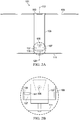
Figure 2A is a side view of an embodiment of the unmanned rotorcraft depicted inFigure 1 according to this disclosure, with the propulsion unit in a rest position; -
Figure 2B is a magnified portion of the view depicted inFigure 2A ; -
Figure 2C is a side view of the unmanned rotorcraft depicted inFigure 2A , with the propulsion unit reoriented such that a propeller axis of the propulsion unit is not aligned with a rotor axis of the main rotor blades; -
Figure 2D is a magnified portion of the view depicted inFigure 2C ; -
Figure 3 is a flow chart illustrating a process for use by the unmanned rotorcraft to determine and maintain a flight path, according to this disclosure; and -
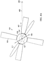
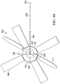
Figures 4A-4C are top views of the unmanned rotorcraft depicted inFigure 1 , illustrating reorientation of the propulsion unit to adjust a heading of the rotorcraft. - In this disclosure, reference may be made to the spatial relationships between various components and to the spatial orientation of various aspects of components as the devices are depicted in the attached drawings. However, as will be recognized by those skilled in the art after a complete reading of this disclosure, the devices, members, apparatuses, etc. described herein may be positioned in any desired orientation. Thus, the use of terms such as "above," "below," "upper," "lower," or other like terms to describe a spatial relationship between various components or to describe the spatial orientation of aspects of such components should be understood to describe a relative relationship between the components or a spatial orientation of aspects of such components, respectively, as the device described herein may be oriented in any desired direction.
- Unmanned rotorcraft having a single motor and a propulsion unit that is reoriented via a single actuator, along with methods for such rotorcraft to maintain a flight path, are disclosed herein. Such unmanned rotorcraft may be provided with collapsible blades that are adapted to deploy when flight is initiated.
-
Figure 1 is an oblique view of anunmanned rotorcraft 101. Rotorcraft 101 comprises anairframe 103, a plurality ofmain rotor blades 105 that are coupled toairframe 103 for rotation therewith, and apropulsion unit 107 having apropeller 109 that includes a plurality ofpropeller blades 111. In this embodiment,airframe 103 has a substantially cylindrical shape that extends from afirst end 113 to asecond end 115. However, it should be appreciated thatairframe 103 can be alternatively implemented with any other suitable geometry. -
Blades 105 are coupled toairframe 103 in fixed positions for rotation therewith about arotor axis 117. As shown,blades 105 are coupled toairframe 103 atfirst end 113 thereof. Eachblade 105 extends from aroot 119 that is coupled toairframe 103 to atip 121. In this embodiment,blades 105 are adapted to be collapsible relative toairframe 103. More specifically,root 119 of eachblade 105 is pivotally coupled toairframe 103.Blades 105 are collapsible towardairframe 103 when rotorcraft 101 is not in flight, for example by foldingblades 105 towardairframe 103 such thattips 121 move inward towardairframe 103 and towardsecond end 115 thereof. - Rotorcraft 101 is configured such that
blades 105 can be secured in respective collapsed positions relative toairframe 103 while rotorcraft 101 is not in flight, and such thatblades 105 deploy from their respective collapsed positions when flight of rotorcraft 101 is initiated. As shown,rotorcraft 101 is adapted such thatblades 105 deploy from their collapsed positions when flight ofrotorcraft 101 is initiated andairframe 103 rotates aboutrotor axis 117. Preferably,blades 105 are adapted to lock into respective deployed positions after flight ofrotorcraft 101 is initiated. - In a preferred implementation,
blades 105 are configured in accordance with desired flight characteristics ofrotorcraft 101. For example, one or more physical characteristics ofblades 105, such as respective dimensions, geometry, camber, and pitch thereof, can be configured based on an expected rotation rate ofairframe 103, to impart desired lift and anti-torque forces torotorcraft 101. - As shown,
propulsion unit 107 is located proximate tosecond end 115 ofairframe 103. In this regard,blades 105 andpropulsion unit 107 are located at opposed ends ofairframe 103.Propulsion unit 107 includes a motor (not shown) that causesblades 111 ofpropeller 109 to rotate about apropeller axis 123. During flight ofrotorcraft 101, rotation ofpropeller 109 imparts counter-rotation toairframe 103, thus causingblades 105 to rotate. For example, rotation ofblades 111 in afirst direction 125 aboutpropeller axis 123 causesblades 105 to rotate in an opposedsecond direction 127 aboutrotor axis 117. It should be appreciated thatfirst direction 125 is not limited to the illustrated counterclockwise rotation. For example,propulsion unit 107 can alternatively be adapted to causeblades 111 to rotate insecond direction 127, which in turn would causeblades 105 to rotate infirst direction 125. - In this embodiment,
blades 111 are adapted to be at least partially collapsible relative toairframe 103. More specifically, eachblade 111 has afixed portion 129 that extends outward from a propeller shaft (not shown) ofpropulsion unit 107 and acollapsible portion 131 that is pivotable relative toairframe 103.Portions 131 ofblades 111 are collapsible towardairframe 103 whenrotorcraft 101 is not in flight, for example by folding theportions 131 towardairframe 103 such thattips 133 ofblades 111 move inward towardairframe 103 and towardfirst end 113 thereof. - Rotorcraft 101 is configured such that
portions 131 ofblades 111 can be secured in respective collapsed positions relative toairframe 103 while rotorcraft 101 is not in flight, and such thatportions 131 deploy from their respective collapsed positions when flight ofrotorcraft 101 is initiated. As shown,rotorcraft 101 is adapted such thatportions 131 deploy from their collapsed positions when flight ofrotorcraft 101 is initiated andpropeller 109 rotates aboutpropeller axis 123. Preferably,portions 131 ofblades 111 are adapted to lock into respective deployed positions after flight ofrotorcraft 101 is initiated. -
Figures 2A-2D are side views ofrotorcraft 101. Whenpropeller axis 123 is coaxially aligned withrotor axis 117, as shown inFigures 2A and 2B , withpropeller 109 rotating,rotorcraft 101 will hover. When hovering,rotorcraft 101 can ascend, descend, or maintain altitude based on rotational speed ofblades 111, which in turn determines rotational speed ofblades 105. Rotational speed ofpropeller 109 can be regulated, for example, by an amount of power supplied topropulsion unit 107. - To enable directional maneuvering,
rotorcraft 101 is adapted such thatpropeller axis 123 can be temporarily moved out of alignment withrotor axis 117. For example,propulsion unit 107 can be coupled toairframe 103 such that it is pivotable in one or more directions relative toairframe 103. - In this embodiment,
propulsion unit 107 is coupled toairframe 103 such that it is pivotable about apivot axis 135. As shown inFigures 2A and 2B ,pivot axis 135 extends out of the page along a perpendicular direction. Rotorcraft 101 further includes anactuator 137 that is adapted to causepropulsion unit 107 to pivot aboutpivot axis 135. As shown,actuator 137 includes afirst end 139 that is coupled toairframe 103 and a second opposedend 141 that is coupled topropulsion unit 107. Preferably,actuator 137 comprises a solenoid-type actuator or linear actuator that is adapted to abruptly switch between two states. - When activated,
actuator 137 causespropulsion unit 107 to be pivoted out of a rest position (as shown inFigures 2A and 2B ) and into a pivoted position (as shown inFigures 2C and 2D ), thereby reorientingpropulsion unit 107 such thatpropeller axis 123 moves out of alignment withrotor axis 117. Misalignment ofpropeller axis 123 relative torotor axis 117 causes adjustment of a thrust vector applied torotorcraft 101 bypropeller 109, thereby causing a direction change in a flight path ofrotorcraft 101.Actuator 137 is further adapted to leavepropulsion unit 107 in the pivoted position for a short interval of time. Preferably,actuator 137 is adapted to, upon completing reorientation ofpropulsion unit 107 to the pivoted position, abruptlyreturn propulsion unit 107 to the rest position such thatpropeller axis 123 is realigned withrotor axis 117. In this regard,actuator 137 is adapted to temporarily reorientpropulsion unit 107 such thatpropeller axis 123 moves out of alignment withrotor axis 117. - In this embodiment,
propulsion unit 107 is coupled toairframe 103 such that it is only pivotable aboutpivot axis 135 along a single path, from the rest position to the pivoted position and back to the rest position as shown inFigures 2A-2D . It should be appreciated that coupling ofpropulsion unit 107 toairframe 103 is not limited to the illustrated implementation in whichpropulsion unit 107 is only pivotable along a single path. For example, in alternative embodiments ofpropulsion unit 107 may be differently coupled toairframe 103, for example using discrete gimbal axes, such that it can be moved from the rest position along one or additional paths to corresponding pivoted positions. -
Rotorcraft 101 further includes a control system (not shown). The control system preferably is adapted to determine a flight path between a current location ofrotorcraft 101 and a target destination forrotorcraft 101 and to ensure thatrotorcraft 101 remains true to the flight path while it flies to the target destination. The control system is further adapted to perform other functions related to operation ofrotorcraft 101, for example starting rotation ofpropeller 109 such thatblades 105 andblades 111 deploy upon determining thatrotorcraft 101 has been deployed for flight, and causing the execution of one or more non-flight-related operations whenrotorcraft 101 reaches the target destination. - The control system includes one or more navigation components. For example, navigation components may include one or more of a Global Positioning System (GPS) receiver, a magnetometer, one or more accelerometers, an inertial measurement unit (IMU), an attitude and heading reference system (AHRS), a rate gyro, and a barometric altitude sensor. The navigation components are adapted to determine a current location in space of
rotorcraft 101 and to track an angular position ofairframe 103. Based on information output by the navigation components, the control system causesactuator 137 to reorientpropulsion unit 107 at appropriate times to keeprotorcraft 101 on course relative to its determined flight path. The control system further includes a communication component that includes an antenna, a memory for storing instructions and data, and a processor. - The processor is adapted to autonomously control flight of
rotorcraft 101, for example by monitoring and governing interactions between itself and other components of the control system, such as information output by the navigation components and signals or data received by the communication component, for example. The control system is preferably implemented on one or more integrated chips and/or circuit boards. - The control system is adapted to perform a plurality of functions related to operation of
rotorcraft 101. For example, the control system is adapted to receive information corresponding to a target location that rotorcraft 101 is to fly to, for example via the communication component. The control system is further adapted to, based on information provided by the navigation components, determine a current location ofrotorcraft 101, determine a flight path from the current location to the target destination when flight ofrotorcraft 101 is initiated, and monitor a current heading ofrotorcraft 101 during flight. The control system is further adapted to track a rotational angular orientation ofairframe 103, for example via one or more of the navigation components. - The control system is further adapted to, based upon a determination of whether the current heading corresponds to the determined flight path, and in accordance with the rotational angular orientation of
airframe 103,cause actuator 137 to reorientpropulsion unit 107 as needed to adjust the current heading ofrotorcraft 101 in accordance with the determined flight path. -
Rotorcraft 101 further includes a power source (not shown), such as one or more batteries. The power source is adapted to provide power to one or more of the control system,propulsion unit 107, andactuator 137. - One or more components of
rotorcraft 101, such asairframe 103,blades 105, andpropeller 109 can be manufactured from a composite material or any other suitable material. Preferably, composite material comprises a fiber-reinforced polymer (FRP) composition that includes filament fibers, such as carbon or glass fibers for example, embedded in a thermoset polymer matrix material such as a thermoplastic resin. The components ofrotorcraft 101 may alternatively be made of any other suitable material. -
Figure 3 is a flowchart illustrating amethod 201 for use byrotorcraft 101 to determine and autonomously maintain a flight path toward a target destination, in accordance with this disclosure. Preferably,method 201 is embodied in computer-executable instructions that are stored in the memory of the control system and that are executed by the processor of the control system. - At
step 203,rotorcraft 101 may receive information related to a target destination that rotorcraft 101 is to fly to. Preferably, the target destination information is received via the communication component of the control system, for example in the form of a signal transmitted using a wireless communication protocol. Such information may comprise, for example, GPS coordinates corresponding to the target destination. - At
step 205,propulsion unit 107 is activated. Activation ofpropulsion unit 107 may be caused by the processor of the control system, and preferably includes causingpropeller 109 to begin rotating at a speed that causesblades 105 andblades 111 to deploy, and that causesairframe 103 to rotate such that sufficient lift is generated byblades 105 to initiate flight ofrotorcraft 101. Preferably, activation ofpropulsion unit 107 is in response to the control system detecting that initiating flight ofrotorcraft 101 is desired. In this embodiment,rotorcraft 101 is adapted to be hand-deployed by a user, for example by tossingrotorcraft 101 away from the user. The control system is preferably adapted to detect a range of such tossing motions, for example via the navigation components.Rotorcraft 101 is adapted to initiate flight along a course that follows the tossing motion. However,rotorcraft 101 may alternatively be adapted to initialize flight in a hover maneuver or in any other suitable manner. - At
step 207, the control system determines a current location ofrotorcraft 101 and determines a current heading ofrotorcraft 101, for example based on information provided by the navigation components. Atstep 209, the control system determines a flight path forrotorcraft 101 from its current location to the target destination. In this embodiment, the processor executes software instructions or logic to determine the flight path, using the target destination information and the current location and current heading information provided by the navigation components. The target destination information comprises one or more coordinates, such as a GPS location for example, that corresponds to the target destination. - At
step 211, the control system determines whether the current heading ofrotorcraft 101 corresponds to the determined flight path to the target destination. The control system is further adapted to, when the current heading ofrotorcraft 101 does not correspond to the flight path to the target destination, proceed to step 213. - At
step 213, the control system causespropulsion unit 107 to be reoriented one or more times to cause the current heading to be adjusted to correspond to the determined flight path. Causingpropulsion unit 107 to be reoriented includes the control system determining a current angular orientation ofairframe 103, and in particular ofactuator 137, relative to the current heading, for example based on information provided by one or more of the navigation components that is adapted to track the angular orientation ofairframe 103. -
Figures 4A-4C are top views of therotorcraft 101, illustrating an example reorientation ofpropulsion unit 107 to adjust a current heading 401 ofrotorcraft 101 to correspond to adetermined flight path 403 to atarget destination 405. Further atstep 213, based on a current rotational speed ofairframe 103 and an amount of time that actuator 137 requires to cycle, that is to reorientpropulsion unit 107 from the rest position to the reoriented position and back to the rest position, the control system determines an angular orientation ofactuator 137 at which to trigger the reorientation ofpropulsion unit 107 such that current heading 401 ofrotorcraft 101 will be adjusted towarddetermined flight path 403. - To illustrate, as seen in
Figure 4A the control system triggers the reorientation ofpropulsion unit 107 whenactuator 137 is at a first angular orientation relative toflight path 403. In response,actuator 137 initiates a cycle and begins pivotingpropulsion unit 107 aboutpivot axis 135. As seen inFigure 4B ,actuator 137 is fully extended such thatpropulsion unit 107 is in the reoriented position. Withpropulsion unit 107 in the reoriented position,propeller axis 123 is out of alignment withrotor axis 117, for example as seen inFigure 2C . The misalignment betweenpropeller axis 123 androtor axis 117 causesairframe 103, and thus a blade plane of rotation defined byblades 105, to tilt towardtarget destination 405 as seen inFigure 4B , thereby adjusting current heading 401 towardflight path 403. As seen inFigure 4C , actuator 137 finishes its cycle, withpropulsion unit 107 returned to its rest position.Method 201 then returns to step 211. - It should be appreciated that the positions of
actuator 137 depicted inFigures 4A-4C are for illustrative purposes, and thatactuator 137 may not cycle completely within a single revolution ofairframe 103. For example, in operation one or more revolutions, such as three to four revolutions, ofairframe 103 may occur in the time required foractuator 137 to complete a cycle of reorientingpropulsion unit 107. It should further be appreciated that the control system may further be adapted to account for one or more additional factors in determining the angular orientation ofactuator 137 at which to trigger the reorientation ofpropulsion unit 107, such as flapping characteristics of one or both ofblades 105 andblades 111, for example. - Alternatively, at
step 211, the control system is further adapted to, when the current heading ofrotorcraft 101 corresponds to the flight path, proceed to step 215. Atstep 215, the control system causesrotorcraft 101 to maintain its current heading. - At
step 217, the control system determines whether the current location ofrotorcraft 101 matches the target destination. The control system is adapted to, when the determination indicates that the current location ofrotorcraft 101 matches the target destination, proceed to step 219. At step 219, the control system causesrotorcraft 101 to maintain its position at the target destination, for example by causingrotorcraft 101 to hover in place. Alternatively, atstep 217, the control system is further adapted to, when the determination indicates that the current location ofrotorcraft 101 does not match the target destination, return to step 211. - It should be appreciated that performance of
method 201 is not strictly limited to the framework of steps as illustrated and described herein. For example, the steps ofmethod 201 need not be performed in the enumerated order, and one or more steps ofmethod 201 may be modified or omitted altogether as appropriate. To illustrate, the control system is not limited to receiving the target destination information prior to activation ofpropulsion unit 107. Stated differently, step 203 may alternatively be performed afterstep 205. To further illustrate, in accordance with alternative embodiments ofmethod 201, one or more steps ofmethod 201 can be modified or omitted. For example, in an example alternative embodiment, a flight path to the target destination can be pre-determined, for example by a user ofrotorcraft 101, and communicated to the control system, for example as part of communication of the target destination information atstep 203. In such an alternative embodiment,step 209 is omitted frommethod 201. It should further be appreciated thatmethod 201 is not limited to being performed by embodiments ofrotorcraft 101. For example, a portion or the entirety ofmethod 201 can be adapted for performance by rotorcraft having configurations, features, etc. that differ from those ofrotorcraft 101. - It should further still be appreciated that
rotorcraft 101 is not limited tocollapsible rotor blades 105 andcollapsible propeller blades 111 as illustrated and described herein. For example,rotorcraft 101 may be provided with blades that are alternatively configured for collapsibility, or alternatively still may be provided with blades that are permanently deployed. It should further be appreciated thatrotorcraft 101 is not limited to having fourblades 105 as shown, and thatrotorcraft 101 can alternatively be configured with more orfewer blades 105. Furthermore,rotorcraft 101 is not limited to having twoblades 111 as shown, androtorcraft 101 can alternatively be configured withmore blades 111. It should further still be appreciated thatblades 105 andblades 111 are not limited to the respective illustrated geometries. For example, as shownblades 105 are longer thanblades 111. However,rotorcraft 101 can be alternatively configured withblades 111 that are the same length as, or are longer than,blades 105. -
Rotorcraft 101 can be provided in varying sizes, but preferably is implemented in a handheld-size scale that enables ease of transport and deployment by a user.Rotorcraft 101 can be manufactured economically, which makes it suitable for use in roles where recovery cannot be guaranteed.Rotorcraft 101 is suitable for implementation in varying roles, for example as a deployable surveillance drone capable of capturing 360° video (e.g., using a camera), as a node in a mobile communications network (e.g., a cell repeater), as a mapping drone (e.g., using lidar, photogrammetry, etc.), or as a vehicle for precise aerial delivery of an explosive (e.g., in a dangerous environment). It should be appreciated thatrotorcraft 101 can be alternatively adapted to be deployed other than by hand. For example,rotorcraft 101 can be alternatively adapted to be launched, or can be alternatively adapted to be dispensed as a sub-munition. - At least one embodiment is disclosed, and variations, combinations, and/or modifications of the embodiment(s) and/or features of the embodiment(s) made by a person having ordinary skill in the art are within the scope of this disclosure. Alternative embodiments that result from combining, integrating, and/or omitting features of the embodiment(s) are also within the scope of this disclosure. Where numerical ranges or limitations are expressly stated, such express ranges or limitations should be understood to include iterative ranges or limitations of like magnitude falling within the expressly stated ranges or limitations (e.g., from about 1 to about 10 includes, 2, 3, 4, etc.; greater than 0.10 includes 0.11, 0.12, 0.13, etc.). For example, whenever a numerical range with a lower limit, Rl, and an upper limit, Ru, is disclosed, any number falling within the range is specifically disclosed. In particular, the following numbers within the range are specifically disclosed: R=Rl +k ∗ (Ru-Rl), wherein k is a variable ranging from 1 percent to 100 percent with a 1 percent increment, i.e., k is 1 percent, 2 percent, 3 percent, 4 percent, 5 percent,...50 percent, 51 percent, 52 percent,..., 95 percent, 96 percent, 95 percent, 98 percent, 99 percent, or 100 percent. Moreover, any numerical range defined by two R numbers as defined in the above is also specifically disclosed.
- Use of the term "optionally" with respect to any element of a claim means that the element is required, or alternatively, the element is not required, both alternatives being within the scope of the claim. Use of broader terms such as comprises, includes, and having should be understood to provide support for narrower terms such as consisting of, consisting essentially of, and comprised substantially of. Accordingly, the scope of protection is not limited by the description set out above but is defined by the claims that follow, that scope including all equivalents of the subject matter of the claims. Each and every claim is incorporated as further disclosure into the specification and the claims are embodiment(s) of the present invention. Also, the phrases "at least one of A, B, and C" and "A and/or B and/or C" should each be interpreted to include only A, only B, only C, or any combination of A, B, and C.
Claims (15)
- An unmanned rotorcraft comprising:an airframe;a plurality of rotor blades that are coupled to the airframe for rotation therewith about a rotor axis;a propulsion unit that is coupled to the airframe, the propulsion unit including a propeller that rotates about a propeller axis; andan actuator that is adapted to temporarily reorient the propulsion unit such that the propeller axis moves out of alignment with the rotor axis,wherein rotation of the propeller by the propulsion unit causes counter-rotation of the airframe and rotor blades.
- The rotorcraft of claim 1, wherein the rotor blades are coupled to the airframe in fixed positions about the rotor axis and are collapsible relative to the airframe.
- The rotorcraft of claim 2, wherein:-(i) the rotor blades are collapsible toward the airframe when the rotorcraft is not in flight; and/or(ii) the rotor blades are adapted to deploy from respective collapsed positions when flight of the rotorcraft is initiated.
- The rotorcraft of claim 2 or of claim 3, wherein the propeller has propeller blades that are collapsible relative to the airframe when the rotorcraft is not in flight.
- The rotorcraft of claim 4, wherein the rotor blades and propeller blades are adapted to deploy from respective collapsed positions when flight of the rotorcraft is initiated.
- The rotorcraft of claim 1 or of any preceding claim, wherein the rotor blades and the propulsion unit are located at opposed ends of the airframe.
- The rotorcraft of claim 1 or of any preceding claim, wherein:-(i) the propulsion unit is coupled to the airframe such that the propulsion unit is pivotable about a pivot axis by the actuator, and optionally or preferably,(ii) the propulsion unit is only pivotable about the pivot axis along a single path from a rest position in which the propeller axis is coaxial with the rotor axis.
- The rotorcraft of claim 1 or of any preceding claim, further comprising:a navigation component,wherein the navigation component causes the actuator to reorient the propulsion unit to maintain a flight path of the rotorcraft.
- The rotorcraft of claim 1 or of any preceding claim, wherein the actuator is further adapted to, upon completing reorientation of the propulsion unit, abruptly return the propulsion unit to a rest position wherein the propeller axis is aligned with the rotor axis.
- A method of operation executed by an unmanned rotorcraft, the method comprising:receiving a target destination for the rotorcraft;activating a propulsion unit coupled to an airframe of the rotorcraft;determining a current location and a current heading of the rotorcraft;determining a flight path from the current location to the target destination;determining whether the current heading corresponds to the flight path;when the current heading corresponds to the flight path, maintaining the current heading; andwhen the current heading does not correspond to the flight path, causing an actuator that is coupled to the airframe and the propulsion unit to temporarily reorient the propulsion unit in accordance with an angular orientation of the actuator relative to the current heading, thereby adjusting the current heading toward the flight path.
- The method of claim 10, wherein the actuator temporarily reorienting the propulsion unit comprises the actuator pivoting the propulsion unit such that a propeller axis thereof moves out of alignment with a rotor axis of the airframe.
- The method of claim 10 or of claim 11, further comprising:recognizing a deployment of the rotorcraft,wherein activating the propulsion unit is performed in response to the recognition of deployment.
- The method of claim 10 or of claim 11 or of claim 12, wherein activating the propulsion unit includes rotating a propeller of the propulsion unit such that the airframe counter-rotates relative to the propeller.
- The method of claim 13, wherein:-(i) activating the propulsion unit includes rotating the propeller such that counter-rotation of the airframe causes deployment of collapsed rotor blades coupled to the airframe for rotation therewith; and/or(ii) activating the propulsion unit includes causing deployment of collapsed propeller blades of the propeller.
- The method of claim 10 or of any of claims 11 to 14, further comprising:determining whether the current location matches the target destination; andwhen the current location matches the target destination, maintaining a position of the rotorcraft proximal to the target destination.
Applications Claiming Priority (1)
| Application Number | Priority Date | Filing Date | Title |
|---|---|---|---|
| US16/889,608 US11524766B2 (en) | 2020-06-01 | 2020-06-01 | Single motor single actuator rotorcraft |
Publications (2)
| Publication Number | Publication Date |
|---|---|
| EP3919372A1 true EP3919372A1 (en) | 2021-12-08 |
| EP3919372B1 EP3919372B1 (en) | 2023-05-10 |
Family
ID=76522759
Family Applications (1)
| Application Number | Title | Priority Date | Filing Date |
|---|---|---|---|
| EP21176695.1A Active EP3919372B1 (en) | 2020-06-01 | 2021-05-28 | Single motor single actuator rotorcraft |
Country Status (2)
| Country | Link |
|---|---|
| US (1) | US11524766B2 (en) |
| EP (1) | EP3919372B1 (en) |
Families Citing this family (10)
| Publication number | Priority date | Publication date | Assignee | Title |
|---|---|---|---|---|
| WO2016077278A1 (en) * | 2014-11-10 | 2016-05-19 | Ascent Aerosystems Llc | Unmanned flying device |
| US11453513B2 (en) | 2018-04-26 | 2022-09-27 | Skydio, Inc. | Autonomous aerial vehicle hardware configuration |
| CN113085462B (en) * | 2021-04-23 | 2023-06-13 | 南京航空航天大学 | A cross-media unmanned aerial vehicle device and its control method |
| US11995996B1 (en) * | 2022-01-11 | 2024-05-28 | United States Of America As Represented By The Secretary Of The Air Force | Method of delivering repeaters in a hostile environment and a drone therefor |
| US11834150B2 (en) | 2022-04-22 | 2023-12-05 | Baxter Aerospace Llc | Aircraft rotor with variable collective blade angle |
| US12202591B2 (en) | 2022-04-22 | 2025-01-21 | Baxter Aerospace Llc | Aircraft with articulatable tail section |
| US11834149B2 (en) * | 2022-04-22 | 2023-12-05 | Baxter Aerospace Llc | Aircraft with articulatable tail section |
| CN115367103B (en) * | 2022-09-23 | 2024-10-15 | 昂海松 | Orthogonal arc rack rotor vector control mechanism based on coaxial double-motor micro unmanned aerial vehicle |
| EP4635846A1 (en) * | 2024-04-16 | 2025-10-22 | Ela Aviacion, S.L. | Gyroplane take-off rotor |
| WO2026002838A1 (en) * | 2024-06-24 | 2026-01-02 | Nordic Air Defence AB | Unmanned flying vehicle |
Citations (6)
| Publication number | Priority date | Publication date | Assignee | Title |
|---|---|---|---|---|
| US7445536B2 (en) * | 2003-06-21 | 2008-11-04 | Air Robot Co., Ltd. | Micro aerial vehicle |
| WO2008140851A2 (en) * | 2007-02-28 | 2008-11-20 | Lawrence John M | Dual rotor vertical takeoff and landing rotorcraft |
| US8469307B2 (en) * | 2004-04-14 | 2013-06-25 | Paul E Arlton | Rotary wing vehicle |
| US20130206915A1 (en) * | 2010-04-22 | 2013-08-15 | Jean-Marc (Joseph) Desaulniers | Vertical take-off and landing multimodal, multienvironment, gyropendular craft with compensatory propulsion and fluidic gradient collimation |
| CN110155316A (en) * | 2019-06-09 | 2019-08-23 | 西北工业大学 | A kind of coaxial twin screw vertically taking off and landing flyer of Moving mass control and its control method |
| US20200070969A1 (en) * | 2018-08-30 | 2020-03-05 | Textron Innovations Inc. | Unmanned Aerial Systems Having Out of Phase Gimballing Axes |
Family Cites Families (6)
| Publication number | Priority date | Publication date | Assignee | Title |
|---|---|---|---|---|
| US6550715B1 (en) * | 2001-12-07 | 2003-04-22 | Lockheed Martin Corporation | Miniature vertical takeoff and landing aircraft |
| KR101210532B1 (en) * | 2008-07-07 | 2012-12-27 | (주)선택이앤티 | 3 Bottom-blade type vehicle |
| US10054939B1 (en) * | 2012-09-22 | 2018-08-21 | Paul G. Applewhite | Unmanned aerial vehicle systems and methods of use |
| WO2016077278A1 (en) * | 2014-11-10 | 2016-05-19 | Ascent Aerosystems Llc | Unmanned flying device |
| WO2018231321A2 (en) * | 2017-03-30 | 2018-12-20 | The Government Of The United States Of America , As Represented By The Secretary Of The Navy | Vertically oriented tube-launchable rotary wing aircraft having respective rotors at opposite ends of a main body |
| US20200231275A1 (en) * | 2019-01-18 | 2020-07-23 | Boaz Barry Groman | Dual rotor system |
-
2020
- 2020-06-01 US US16/889,608 patent/US11524766B2/en active Active
-
2021
- 2021-05-28 EP EP21176695.1A patent/EP3919372B1/en active Active
Patent Citations (6)
| Publication number | Priority date | Publication date | Assignee | Title |
|---|---|---|---|---|
| US7445536B2 (en) * | 2003-06-21 | 2008-11-04 | Air Robot Co., Ltd. | Micro aerial vehicle |
| US8469307B2 (en) * | 2004-04-14 | 2013-06-25 | Paul E Arlton | Rotary wing vehicle |
| WO2008140851A2 (en) * | 2007-02-28 | 2008-11-20 | Lawrence John M | Dual rotor vertical takeoff and landing rotorcraft |
| US20130206915A1 (en) * | 2010-04-22 | 2013-08-15 | Jean-Marc (Joseph) Desaulniers | Vertical take-off and landing multimodal, multienvironment, gyropendular craft with compensatory propulsion and fluidic gradient collimation |
| US20200070969A1 (en) * | 2018-08-30 | 2020-03-05 | Textron Innovations Inc. | Unmanned Aerial Systems Having Out of Phase Gimballing Axes |
| CN110155316A (en) * | 2019-06-09 | 2019-08-23 | 西北工业大学 | A kind of coaxial twin screw vertically taking off and landing flyer of Moving mass control and its control method |
Also Published As
| Publication number | Publication date |
|---|---|
| US20210371085A1 (en) | 2021-12-02 |
| US11524766B2 (en) | 2022-12-13 |
| EP3919372B1 (en) | 2023-05-10 |
Similar Documents
| Publication | Publication Date | Title |
|---|---|---|
| US11524766B2 (en) | Single motor single actuator rotorcraft | |
| US12351296B2 (en) | Adaptive thrust vector unmanned aerial vehicle | |
| US6347764B1 (en) | Gun hardened, rotary winged, glide and descent device | |
| US9522732B1 (en) | Unmanned aerial vehicle perching maneuver | |
| EP3797070B1 (en) | Folding concentrically mounted propeller blades for drag reduction | |
| EP3097014B1 (en) | Multicopters with variable flight characteristics | |
| US9527588B1 (en) | Unmanned aircraft system (UAS) with active energy harvesting and power management | |
| US11453492B2 (en) | Transformable hovering rotorcraft | |
| US10435149B2 (en) | UAV rotor system | |
| US11932428B2 (en) | Rotary-wing, hover-capable aircraft and methods | |
| US12099128B2 (en) | Methods and systems for utilizing dual global positioning system (GPS) antennas in vertical take-off and landing (VTOL) aerial vehicles | |
| WO2018182883A1 (en) | Double folding drone arms with landing gear | |
| CN113955094A (en) | Unmanned aerial vehicle | |
| US10717526B2 (en) | UAV with in-flight adjustable wings | |
| CN108594839A (en) | Control method, aircraft based on more vectoring technologies and storage medium | |
| CN111587409A (en) | UAV launch method and system | |
| CN112230673A (en) | UAV and UAV take-off method | |
| WO2022215266A1 (en) | Flight vehicle landing method, flight vehicle, information processing device, and program | |
| KR20170087370A (en) | The unmanned aerial vehicle capable of flying under changeable weather | |
| EP3368411B1 (en) | Rotary-wing air vehicle and method and apparatus for launch and recovery thereof | |
| JP2019043394A (en) | Rotorcraft | |
| Rahman et al. | Design and implementation of a Y-copter: Aerobatic version | |
| JP2020164120A (en) | Drone and flight stabilization method |
Legal Events
| Date | Code | Title | Description |
|---|---|---|---|
| PUAI | Public reference made under article 153(3) epc to a published international application that has entered the european phase |
Free format text: ORIGINAL CODE: 0009012 |
|
| STAA | Information on the status of an ep patent application or granted ep patent |
Free format text: STATUS: EXAMINATION IS IN PROGRESS |
|
| 17P | Request for examination filed |
Effective date: 20210528 |
|
| AK | Designated contracting states |
Kind code of ref document: A1 Designated state(s): AL AT BE BG CH CY CZ DE DK EE ES FI FR GB GR HR HU IE IS IT LI LT LU LV MC MK MT NL NO PL PT RO RS SE SI SK SM TR |
|
| B565 | Issuance of search results under rule 164(2) epc |
Effective date: 20211028 |
|
| GRAP | Despatch of communication of intention to grant a patent |
Free format text: ORIGINAL CODE: EPIDOSNIGR1 |
|
| STAA | Information on the status of an ep patent application or granted ep patent |
Free format text: STATUS: GRANT OF PATENT IS INTENDED |
|
| INTG | Intention to grant announced |
Effective date: 20221122 |
|
| GRAS | Grant fee paid |
Free format text: ORIGINAL CODE: EPIDOSNIGR3 |
|
| GRAA | (expected) grant |
Free format text: ORIGINAL CODE: 0009210 |
|
| STAA | Information on the status of an ep patent application or granted ep patent |
Free format text: STATUS: THE PATENT HAS BEEN GRANTED |
|
| AK | Designated contracting states |
Kind code of ref document: B1 Designated state(s): AL AT BE BG CH CY CZ DE DK EE ES FI FR GB GR HR HU IE IS IT LI LT LU LV MC MK MT NL NO PL PT RO RS SE SI SK SM TR |
|
| REG | Reference to a national code |
Ref country code: GB Ref legal event code: FG4D |
|
| REG | Reference to a national code |
Ref country code: AT Ref legal event code: REF Ref document number: 1566452 Country of ref document: AT Kind code of ref document: T Effective date: 20230515 Ref country code: CH Ref legal event code: EP |
|
| REG | Reference to a national code |
Ref country code: DE Ref legal event code: R096 Ref document number: 602021002257 Country of ref document: DE |
|
| REG | Reference to a national code |
Ref country code: IE Ref legal event code: FG4D |
|
| REG | Reference to a national code |
Ref country code: LT Ref legal event code: MG9D |
|
| P01 | Opt-out of the competence of the unified patent court (upc) registered |
Effective date: 20230802 |
|
| REG | Reference to a national code |
Ref country code: NL Ref legal event code: MP Effective date: 20230510 |
|
| REG | Reference to a national code |
Ref country code: AT Ref legal event code: MK05 Ref document number: 1566452 Country of ref document: AT Kind code of ref document: T Effective date: 20230510 |
|
| PG25 | Lapsed in a contracting state [announced via postgrant information from national office to epo] |
Ref country code: SE Free format text: LAPSE BECAUSE OF FAILURE TO SUBMIT A TRANSLATION OF THE DESCRIPTION OR TO PAY THE FEE WITHIN THE PRESCRIBED TIME-LIMIT Effective date: 20230510 Ref country code: PT Free format text: LAPSE BECAUSE OF FAILURE TO SUBMIT A TRANSLATION OF THE DESCRIPTION OR TO PAY THE FEE WITHIN THE PRESCRIBED TIME-LIMIT Effective date: 20230911 Ref country code: NO Free format text: LAPSE BECAUSE OF FAILURE TO SUBMIT A TRANSLATION OF THE DESCRIPTION OR TO PAY THE FEE WITHIN THE PRESCRIBED TIME-LIMIT Effective date: 20230810 Ref country code: NL Free format text: LAPSE BECAUSE OF FAILURE TO SUBMIT A TRANSLATION OF THE DESCRIPTION OR TO PAY THE FEE WITHIN THE PRESCRIBED TIME-LIMIT Effective date: 20230510 Ref country code: ES Free format text: LAPSE BECAUSE OF FAILURE TO SUBMIT A TRANSLATION OF THE DESCRIPTION OR TO PAY THE FEE WITHIN THE PRESCRIBED TIME-LIMIT Effective date: 20230510 Ref country code: AT Free format text: LAPSE BECAUSE OF FAILURE TO SUBMIT A TRANSLATION OF THE DESCRIPTION OR TO PAY THE FEE WITHIN THE PRESCRIBED TIME-LIMIT Effective date: 20230510 |
|
| PG25 | Lapsed in a contracting state [announced via postgrant information from national office to epo] |
Ref country code: RS Free format text: LAPSE BECAUSE OF FAILURE TO SUBMIT A TRANSLATION OF THE DESCRIPTION OR TO PAY THE FEE WITHIN THE PRESCRIBED TIME-LIMIT Effective date: 20230510 Ref country code: PL Free format text: LAPSE BECAUSE OF FAILURE TO SUBMIT A TRANSLATION OF THE DESCRIPTION OR TO PAY THE FEE WITHIN THE PRESCRIBED TIME-LIMIT Effective date: 20230510 Ref country code: LV Free format text: LAPSE BECAUSE OF FAILURE TO SUBMIT A TRANSLATION OF THE DESCRIPTION OR TO PAY THE FEE WITHIN THE PRESCRIBED TIME-LIMIT Effective date: 20230510 Ref country code: LT Free format text: LAPSE BECAUSE OF FAILURE TO SUBMIT A TRANSLATION OF THE DESCRIPTION OR TO PAY THE FEE WITHIN THE PRESCRIBED TIME-LIMIT Effective date: 20230510 Ref country code: IS Free format text: LAPSE BECAUSE OF FAILURE TO SUBMIT A TRANSLATION OF THE DESCRIPTION OR TO PAY THE FEE WITHIN THE PRESCRIBED TIME-LIMIT Effective date: 20230910 Ref country code: HR Free format text: LAPSE BECAUSE OF FAILURE TO SUBMIT A TRANSLATION OF THE DESCRIPTION OR TO PAY THE FEE WITHIN THE PRESCRIBED TIME-LIMIT Effective date: 20230510 Ref country code: GR Free format text: LAPSE BECAUSE OF FAILURE TO SUBMIT A TRANSLATION OF THE DESCRIPTION OR TO PAY THE FEE WITHIN THE PRESCRIBED TIME-LIMIT Effective date: 20230811 |
|
| PG25 | Lapsed in a contracting state [announced via postgrant information from national office to epo] |
Ref country code: FI Free format text: LAPSE BECAUSE OF FAILURE TO SUBMIT A TRANSLATION OF THE DESCRIPTION OR TO PAY THE FEE WITHIN THE PRESCRIBED TIME-LIMIT Effective date: 20230510 |
|
| PG25 | Lapsed in a contracting state [announced via postgrant information from national office to epo] |
Ref country code: SK Free format text: LAPSE BECAUSE OF FAILURE TO SUBMIT A TRANSLATION OF THE DESCRIPTION OR TO PAY THE FEE WITHIN THE PRESCRIBED TIME-LIMIT Effective date: 20230510 |
|
| REG | Reference to a national code |
Ref country code: BE Ref legal event code: MM Effective date: 20230531 |
|
| PG25 | Lapsed in a contracting state [announced via postgrant information from national office to epo] |
Ref country code: SM Free format text: LAPSE BECAUSE OF FAILURE TO SUBMIT A TRANSLATION OF THE DESCRIPTION OR TO PAY THE FEE WITHIN THE PRESCRIBED TIME-LIMIT Effective date: 20230510 Ref country code: SK Free format text: LAPSE BECAUSE OF FAILURE TO SUBMIT A TRANSLATION OF THE DESCRIPTION OR TO PAY THE FEE WITHIN THE PRESCRIBED TIME-LIMIT Effective date: 20230510 Ref country code: RO Free format text: LAPSE BECAUSE OF FAILURE TO SUBMIT A TRANSLATION OF THE DESCRIPTION OR TO PAY THE FEE WITHIN THE PRESCRIBED TIME-LIMIT Effective date: 20230510 Ref country code: LU Free format text: LAPSE BECAUSE OF NON-PAYMENT OF DUE FEES Effective date: 20230528 Ref country code: EE Free format text: LAPSE BECAUSE OF FAILURE TO SUBMIT A TRANSLATION OF THE DESCRIPTION OR TO PAY THE FEE WITHIN THE PRESCRIBED TIME-LIMIT Effective date: 20230510 Ref country code: DK Free format text: LAPSE BECAUSE OF FAILURE TO SUBMIT A TRANSLATION OF THE DESCRIPTION OR TO PAY THE FEE WITHIN THE PRESCRIBED TIME-LIMIT Effective date: 20230510 Ref country code: CZ Free format text: LAPSE BECAUSE OF FAILURE TO SUBMIT A TRANSLATION OF THE DESCRIPTION OR TO PAY THE FEE WITHIN THE PRESCRIBED TIME-LIMIT Effective date: 20230510 |
|
| REG | Reference to a national code |
Ref country code: DE Ref legal event code: R097 Ref document number: 602021002257 Country of ref document: DE |
|
| PG25 | Lapsed in a contracting state [announced via postgrant information from national office to epo] |
Ref country code: MC Free format text: LAPSE BECAUSE OF FAILURE TO SUBMIT A TRANSLATION OF THE DESCRIPTION OR TO PAY THE FEE WITHIN THE PRESCRIBED TIME-LIMIT Effective date: 20230510 |
|
| REG | Reference to a national code |
Ref country code: IE Ref legal event code: MM4A |
|
| PG25 | Lapsed in a contracting state [announced via postgrant information from national office to epo] |
Ref country code: MC Free format text: LAPSE BECAUSE OF FAILURE TO SUBMIT A TRANSLATION OF THE DESCRIPTION OR TO PAY THE FEE WITHIN THE PRESCRIBED TIME-LIMIT Effective date: 20230510 |
|
| PLBE | No opposition filed within time limit |
Free format text: ORIGINAL CODE: 0009261 |
|
| STAA | Information on the status of an ep patent application or granted ep patent |
Free format text: STATUS: NO OPPOSITION FILED WITHIN TIME LIMIT |
|
| PG25 | Lapsed in a contracting state [announced via postgrant information from national office to epo] |
Ref country code: IE Free format text: LAPSE BECAUSE OF NON-PAYMENT OF DUE FEES Effective date: 20230528 |
|
| 26N | No opposition filed |
Effective date: 20240213 |
|
| PG25 | Lapsed in a contracting state [announced via postgrant information from national office to epo] |
Ref country code: IE Free format text: LAPSE BECAUSE OF NON-PAYMENT OF DUE FEES Effective date: 20230528 |
|
| PG25 | Lapsed in a contracting state [announced via postgrant information from national office to epo] |
Ref country code: SI Free format text: LAPSE BECAUSE OF FAILURE TO SUBMIT A TRANSLATION OF THE DESCRIPTION OR TO PAY THE FEE WITHIN THE PRESCRIBED TIME-LIMIT Effective date: 20230510 |
|
| PG25 | Lapsed in a contracting state [announced via postgrant information from national office to epo] |
Ref country code: SI Free format text: LAPSE BECAUSE OF FAILURE TO SUBMIT A TRANSLATION OF THE DESCRIPTION OR TO PAY THE FEE WITHIN THE PRESCRIBED TIME-LIMIT Effective date: 20230510 Ref country code: BE Free format text: LAPSE BECAUSE OF NON-PAYMENT OF DUE FEES Effective date: 20230531 |
|
| PG25 | Lapsed in a contracting state [announced via postgrant information from national office to epo] |
Ref country code: BG Free format text: LAPSE BECAUSE OF FAILURE TO SUBMIT A TRANSLATION OF THE DESCRIPTION OR TO PAY THE FEE WITHIN THE PRESCRIBED TIME-LIMIT Effective date: 20230510 |
|
| PG25 | Lapsed in a contracting state [announced via postgrant information from national office to epo] |
Ref country code: BG Free format text: LAPSE BECAUSE OF FAILURE TO SUBMIT A TRANSLATION OF THE DESCRIPTION OR TO PAY THE FEE WITHIN THE PRESCRIBED TIME-LIMIT Effective date: 20230510 |
|
| REG | Reference to a national code |
Ref country code: CH Ref legal event code: PL |
|
| PG25 | Lapsed in a contracting state [announced via postgrant information from national office to epo] |
Ref country code: CH Free format text: LAPSE BECAUSE OF NON-PAYMENT OF DUE FEES Effective date: 20240531 |
|
| PG25 | Lapsed in a contracting state [announced via postgrant information from national office to epo] |
Ref country code: CY Free format text: LAPSE BECAUSE OF FAILURE TO SUBMIT A TRANSLATION OF THE DESCRIPTION OR TO PAY THE FEE WITHIN THE PRESCRIBED TIME-LIMIT; INVALID AB INITIO Effective date: 20210528 |
|
| PG25 | Lapsed in a contracting state [announced via postgrant information from national office to epo] |
Ref country code: HU Free format text: LAPSE BECAUSE OF FAILURE TO SUBMIT A TRANSLATION OF THE DESCRIPTION OR TO PAY THE FEE WITHIN THE PRESCRIBED TIME-LIMIT; INVALID AB INITIO Effective date: 20210528 |
|
| PG25 | Lapsed in a contracting state [announced via postgrant information from national office to epo] |
Ref country code: TR Free format text: LAPSE BECAUSE OF FAILURE TO SUBMIT A TRANSLATION OF THE DESCRIPTION OR TO PAY THE FEE WITHIN THE PRESCRIBED TIME-LIMIT Effective date: 20230510 |
|
| PG25 | Lapsed in a contracting state [announced via postgrant information from national office to epo] |
Ref country code: CH Free format text: THE PATENT HAS BEEN ANNULLED BY A DECISION OF A NATIONAL AUTHORITY Effective date: 20240531 |
|
| PGFP | Annual fee paid to national office [announced via postgrant information from national office to epo] |
Ref country code: GB Payment date: 20260527 Year of fee payment: 6 |
|
| PGFP | Annual fee paid to national office [announced via postgrant information from national office to epo] |
Ref country code: IT Payment date: 20260520 Year of fee payment: 6 |
|
| PGFP | Annual fee paid to national office [announced via postgrant information from national office to epo] |
Ref country code: DE Payment date: 20260528 Year of fee payment: 6 |
|
| PGFP | Annual fee paid to national office [announced via postgrant information from national office to epo] |
Ref country code: FR Payment date: 20260525 Year of fee payment: 6 |