EP3919264A1 - Device for positioning die-cutting rollers in rotary cutting machines - Google Patents
Device for positioning die-cutting rollers in rotary cutting machines Download PDFInfo
- Publication number
- EP3919264A1 EP3919264A1 EP19913680.5A EP19913680A EP3919264A1 EP 3919264 A1 EP3919264 A1 EP 3919264A1 EP 19913680 A EP19913680 A EP 19913680A EP 3919264 A1 EP3919264 A1 EP 3919264A1
- Authority
- EP
- European Patent Office
- Prior art keywords
- die
- roller
- cutting
- rollers
- cylinder
- Prior art date
- Legal status (The legal status is an assumption and is not a legal conclusion. Google has not performed a legal analysis and makes no representation as to the accuracy of the status listed.)
- Granted
Links
Images

Classifications
-
- B—PERFORMING OPERATIONS; TRANSPORTING
- B26—HAND CUTTING TOOLS; CUTTING; SEVERING
- B26D—CUTTING; DETAILS COMMON TO MACHINES FOR PERFORATING, PUNCHING, CUTTING-OUT, STAMPING-OUT OR SEVERING
- B26D7/00—Details of apparatus for cutting, cutting-out, stamping-out, punching, perforating, or severing by means other than cutting
- B26D7/26—Means for mounting or adjusting the cutting member; Means for adjusting the stroke of the cutting member
- B26D7/2628—Means for adjusting the position of the cutting member
- B26D7/265—Journals, bearings or supports for positioning rollers or cylinders relatively to each other
-
- B—PERFORMING OPERATIONS; TRANSPORTING
- B26—HAND CUTTING TOOLS; CUTTING; SEVERING
- B26F—PERFORATING; PUNCHING; CUTTING-OUT; STAMPING-OUT; SEVERING BY MEANS OTHER THAN CUTTING
- B26F1/00—Perforating; Punching; Cutting-out; Stamping-out; Apparatus therefor
- B26F1/38—Cutting-out; Stamping-out
- B26F1/384—Cutting-out; Stamping-out using rotating drums
-
- B—PERFORMING OPERATIONS; TRANSPORTING
- B31—MAKING ARTICLES OF PAPER, CARDBOARD OR MATERIAL WORKED IN A MANNER ANALOGOUS TO PAPER; WORKING PAPER, CARDBOARD OR MATERIAL WORKED IN A MANNER ANALOGOUS TO PAPER
- B31D—MAKING ARTICLES OF PAPER, CARDBOARD OR MATERIAL WORKED IN A MANNER ANALOGOUS TO PAPER, NOT PROVIDED FOR IN SUBCLASSES B31B OR B31C
- B31D1/00—Multiple-step processes for making flat articles ; Making flat articles
- B31D1/02—Multiple-step processes for making flat articles ; Making flat articles the articles being labels or tags
-
- B—PERFORMING OPERATIONS; TRANSPORTING
- B31—MAKING ARTICLES OF PAPER, CARDBOARD OR MATERIAL WORKED IN A MANNER ANALOGOUS TO PAPER; WORKING PAPER, CARDBOARD OR MATERIAL WORKED IN A MANNER ANALOGOUS TO PAPER
- B31D—MAKING ARTICLES OF PAPER, CARDBOARD OR MATERIAL WORKED IN A MANNER ANALOGOUS TO PAPER, NOT PROVIDED FOR IN SUBCLASSES B31B OR B31C
- B31D2201/00—Multiple-step processes for making flat articles
- B31D2201/02—Multiple-step processes for making flat articles the articles being labels or tags
Definitions
- the present invention relates to a device which has been especially conceived to allow fine adjustment of the positioning between the cutting cylinder and the base cylinder for label work and the like, when an extremely accurate precision of cutting depth is required, in machines based on rotary cylinders intended for that purpose.
- the object of the invention is to provide a mechanism that allows the automatic regulation of the space that is defined between the carrier cylinder of the cutting die and the base cylinder on which the carrier sheet of the material to be die-cut slides, such as labels, so that the machine can adapt to different thicknesses, without damaging the base sheet on which they adhere.
- the starting point is a sheet wherein a base layer of paraffined, siliconised or similar paper participates, on which an adhesive sheet per se is arranged, intended to be die-cut to obtain a plurality of adhesive labels of a smaller size.
- the object of the device of the invention is to automate this process of regulating the positioning of the die-carrying cylinder, in order to avoid human errors and simplify this manoeuvre.
- the invention is focussed on the fact that associated to the rotation shaft of the die-carrying cylinder, and in correspondence with both ends thereof, an eccentric cam is arranged, which is linked thereto through bearings or bushings, an eccentric cam from which a lateral arm emerges which ends in a gear arc on which acts an endless screw associated to an impulse motor, with which the movement of said endless screw and consequently the angular movement of the eccentric cam, is finely controlled, which will cause,
- the electric impulse motor can be manually controlled through a control interface, implemented in the machine itself or externally, or it can be regulated in a fully automated way through the data entered by the computer system associated with the machine.
- the device of the invention is intended in this case to be implemented in roller-based label cutting machines, wherein a series of guide rollers (1) are used for the sheets to be die-cut, in such way that the die-cutting process takes place when said sheets are passed through a pair of rollers synchronised with each other from respective gears (2-3), establishing a base roller (4) and an upper roller (5), die-carrying, so that in this case the upper roller (5) is vertically movable on guides (6) established on the support frame (7) of the mechanism.
- the shaft (9) of the die-carrying cylinder is offset by a small distance from the shaft (16) of the cam on which it rotates internally, so that, when the endless screw (14) is driven by means of the electric impulse motor, it causes an angular displacement of said eccentric cam (10), as shown in figure 4 , which causes a vertical displacement (D), of the shaft (9) of the die-carrying upper roller (5).
- This device can also be used in rotary die cutting machines, when it is necessary to bring the die closer to the sheet to be cut due to its wear.
- the mechanism can be located as mentioned in the magnetic cylinder carrying the dies (5), or in the base cylinder (4), since it is indistinct in order to carry out the intended approach, thus, in some cases it can even be incorporated into both cylinders.
- the electric impulse motor can be manually controlled through a control interface, implemented in the machine itself and/or externally, for example through an application controlled by a mobile device, tablet or similar, and/or, be regulated in a fully automated way through the data entered by the computer system associated with the machine.
Landscapes
- Life Sciences & Earth Sciences (AREA)
- Forests & Forestry (AREA)
- Engineering & Computer Science (AREA)
- Mechanical Engineering (AREA)
- Making Paper Articles (AREA)
- Perforating, Stamping-Out Or Severing By Means Other Than Cutting (AREA)
Abstract
Description
- The present invention relates to a device which has been especially conceived to allow fine adjustment of the positioning between the cutting cylinder and the base cylinder for label work and the like, when an extremely accurate precision of cutting depth is required, in machines based on rotary cylinders intended for that purpose.
- The object of the invention is to provide a mechanism that allows the automatic regulation of the space that is defined between the carrier cylinder of the cutting die and the base cylinder on which the carrier sheet of the material to be die-cut slides, such as labels, so that the machine can adapt to different thicknesses, without damaging the base sheet on which they adhere.
- It is therefore a micrometric movement, but it is decisive to ensure that the resulting product is of the highest quality.
- In the practical scope of the invention (that of the roller-based die-cutting machines used for the die-cutting of adhesive labels) the starting point is a sheet wherein a base layer of paraffined, siliconised or similar paper participates, on which an adhesive sheet per se is arranged, intended to be die-cut to obtain a plurality of adhesive labels of a smaller size.
- These labels must be properly die-cut without the blades damaging the base sheet on which they rest, so that the sheet has a one-piece appearance when it comes out of the machine, i.e. that the labels can be separated one by one from a single common sheet.
- The problem is that these sheets can have different thicknesses depending on the type of paper used, so the distance between the base cylinder and the die-carrying cylinder must be adjusted so that the die blades do not damage the base sheet, a manoeuvre that to date is carried out by hand, by means of manual micrometers associated with the shaft of the die-carrying cylinder or the shaft of the base cylinder.
- The object of the device of the invention is to automate this process of regulating the positioning of the die-carrying cylinder, in order to avoid human errors and simplify this manoeuvre.
- For this purpose, and more specifically, starting from the conventional structure of machines of this type, wherein a base roller is used to support the sheet to be die-cut, on which a magnetic roller rotates, to which the cutting plates or dies of the labels to be obtained are fixed perimetrically, rollers that are synchronised by means of respective end gears and solidly fixed thereto, the shaft of the die-carrying upper roller being arranged on a vertical guide which allows a small vertical play, micrometric, and capable of being absorbed by the height/depth of the teeth participating in both synchronization gears, the invention is focussed on the fact that associated to the rotation shaft of the die-carrying cylinder, and in correspondence with both ends thereof, an eccentric cam is arranged, which is linked thereto through bearings or bushings, an eccentric cam from which a lateral arm emerges which ends in a gear arc on which acts an endless screw associated to an impulse motor, with which the movement of said endless screw and consequently the angular movement of the eccentric cam, is finely controlled, which will cause, depending on the direction of rotation applied by the motor, that the shaft of the die-carrying cylinder, and consequently the latter, to move slightly upwards or downwards, a micrometric distance, sufficient to correctly adjust the mechanism to the type of labels to be used, a movement, as previously mentioned and as is conventional, that does not affect the synchronisation in the movement between rollers, since this movement is significantly less than the height of the teeth of the gears that link both rollers.
- The electric impulse motor can be manually controlled through a control interface, implemented in the machine itself or externally, or it can be regulated in a fully automated way through the data entered by the computer system associated with the machine.
- In this way, a totally reliable and precise mechanism is achieved that allows the dies to be adapted to the different thicknesses of paper used in each case, without damaging the base sheet of the adhesive labels to be obtained, significantly minimising adaptation times and avoiding human errors.
- As a complement to the description that will be provided herein, and for the purpose of helping to make the features of the invention more readily understandable, according to a preferred practical exemplary embodiment thereof, said description is accompanied by a set of drawings constituting an integral part thereof in which, by way of illustration and not limitation, the following is represented:
-
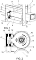
Figure 1 shows a perspective view of a label cutting machine based on rotating cylinders wherein a positioning device made in accordance with the object of the present invention is implemented. -
Figure 2 shows a profile view of the assembly of the previous figure at the level of the cylinder on which the mechanism of the invention is applied. -
Figures 3 and 4 show a simplified and widely exaggerated diagram of the operation of the device of the invention, since the eccentricity of the cam that participates in the invention is so small that it cannot even be appreciated in the real planes of theFigures 1 and 2 , so that said operation becomes clearer in view of these two new schematic figures. - In view of the outlined figures, it can be seen how the device of the invention is intended in this case to be implemented in roller-based label cutting machines, wherein a series of guide rollers (1) are used for the sheets to be die-cut, in such way that the die-cutting process takes place when said sheets are passed through a pair of rollers synchronised with each other from respective gears (2-3), establishing a base roller (4) and an upper roller (5), die-carrying, so that in this case the upper roller (5) is vertically movable on guides (6) established on the support frame (7) of the mechanism.
- As can be seen in
Figures 1 and 2 , the ends of the shafts of the upper roller (5) are linked to respective mechanisms (8) of vertical movement of said upper roller (5), so that said shafts (9) are linked to an eccentric cam (10) by means of bearings or gears (11), an eccentric cam from which a lateral arm (12) emerges that ends in a gear arc (13) on which acts an endless screw (14) associated with an impulse motor (15), with which the movement of said endless screw is finely controlled, said mechanism being duly protected in the corresponding casing (17). - Given that the eccentricity of the cam is minimal, as micrometric movements are required, in
Figures 3 and 4 the behaviour of the cam is exaggerated so that it can be better understood, although, as has just been said, these are minimal movements that are easily absorbed by the teeth of the gears (2 and 3) that link both rollers. - Well, as can be exaggeratedly seen in
figure 3 , the shaft (9) of the die-carrying cylinder is offset by a small distance from the shaft (16) of the cam on which it rotates internally, so that, when the endless screw (14) is driven by means of the electric impulse motor, it causes an angular displacement of said eccentric cam (10), as shown infigure 4 , which causes a vertical displacement (D), of the shaft (9) of the die-carrying upper roller (5). - This device can also be used in rotary die cutting machines, when it is necessary to bring the die closer to the sheet to be cut due to its wear.
- It should be noted that the mechanism can be located as mentioned in the magnetic cylinder carrying the dies (5), or in the base cylinder (4), since it is indistinct in order to carry out the intended approach, thus, in some cases it can even be incorporated into both cylinders.
- Finally, it only remains to point out that, as mentioned above, the electric impulse motor can be manually controlled through a control interface, implemented in the machine itself and/or externally, for example through an application controlled by a mobile device, tablet or similar, and/or, be regulated in a fully automated way through the data entered by the computer system associated with the machine.
Claims (4)
- A device for positioning die-cutting rollers in rotary cutting machines, wherein the carrier sheet for the labels to be obtained is passed through a pair of rollers synchronized with each other from respective gears (2-3), establishing a base roller (4) and an upper roller (5), die-carrying, the upper roller (5) being vertically movable on guides (6) established on the support frame (7) of the mechanism, characterised in that respective eccentric cams (10) are linked to the ends of the shafts (9) of the upper roller (5) by means of bearings or gears (11), eccentric cams (10) from which a lateral arm (12) emerges that ends in a gear arc (13) on which an endless screw (14) acts associated with an impulse motor (15), associated with an internal and/or external control interface, manually operated and/or computerised.
- The device for positioning die-cutting rollers in rotary cutting machines, according to the preceding claim, characterised in that the movement mechanism of the roller is on the base roller (4).
- The device for positioning die-cutting rollers in rotary cutting machines, according to the first claim, characterised in that the movement mechanism is incorporated in the upper roller (5) and in the base roller (4).
- The device for positioning die-cutting rollers in rotary cutting machines, according to preceding claims, characterised in that it allows the approach of the upper roller (5) and the base roller (4), to compensate for the wear of the die.
Applications Claiming Priority (1)
| Application Number | Priority Date | Filing Date | Title |
|---|---|---|---|
| PCT/ES2019/070055 WO2020157344A1 (en) | 2019-02-01 | 2019-02-01 | Device for positioning die-cutting rollers in rotary cutting machines |
Publications (4)
| Publication Number | Publication Date |
|---|---|
| EP3919264A1 true EP3919264A1 (en) | 2021-12-08 |
| EP3919264A4 EP3919264A4 (en) | 2022-08-24 |
| EP3919264B1 EP3919264B1 (en) | 2023-07-05 |
| EP3919264C0 EP3919264C0 (en) | 2023-07-05 |
Family
ID=71841359
Family Applications (1)
| Application Number | Title | Priority Date | Filing Date |
|---|---|---|---|
| EP19913680.5A Active EP3919264B1 (en) | 2019-02-01 | 2019-02-01 | Device for positioning die-cutting rollers in rotary cutting machines |
Country Status (2)
| Country | Link |
|---|---|
| EP (1) | EP3919264B1 (en) |
| WO (1) | WO2020157344A1 (en) |
Cited By (1)
| Publication number | Priority date | Publication date | Assignee | Title |
|---|---|---|---|---|
| FI131576B1 (en) * | 2022-02-03 | 2025-07-11 | Valmet Technologies Oy | Cutting roll, cross-cutting device and sheet cutter of pulp drying machine |
Families Citing this family (1)
| Publication number | Priority date | Publication date | Assignee | Title |
|---|---|---|---|---|
| WO2023073253A1 (en) * | 2021-10-27 | 2023-05-04 | Tecnocut, S.L. | Device for positioning die-cutting rollers in rotary and semi-rotary cutting machines |
Family Cites Families (5)
| Publication number | Priority date | Publication date | Assignee | Title |
|---|---|---|---|---|
| US1785250A (en) * | 1928-01-31 | 1930-12-16 | Eberhardt Stanley Leopol Henry | Method of and apparatus for making tickets |
| GB532018A (en) * | 1939-04-12 | 1941-01-15 | Maurice Bezencenet | Non-drying adhesive labels and method and apparatus for making the same |
| JPS5964295A (en) * | 1982-09-30 | 1984-04-12 | 株式会社磯輪鉄工所 | Punching mechanism for sheet-shaped material |
| JP6043584B2 (en) * | 2012-10-24 | 2016-12-14 | 株式会社トッパンTdkレーベル | Label die cutting device and label die cutting method |
| US10391662B2 (en) * | 2013-03-07 | 2019-08-27 | Bobst Mex Sa | Adjustable converting arrangement for a flat substrate, cassette, unit and machine provided therewith |
-
2019
- 2019-02-01 EP EP19913680.5A patent/EP3919264B1/en active Active
- 2019-02-01 WO PCT/ES2019/070055 patent/WO2020157344A1/en not_active Ceased
Cited By (1)
| Publication number | Priority date | Publication date | Assignee | Title |
|---|---|---|---|---|
| FI131576B1 (en) * | 2022-02-03 | 2025-07-11 | Valmet Technologies Oy | Cutting roll, cross-cutting device and sheet cutter of pulp drying machine |
Also Published As
| Publication number | Publication date |
|---|---|
| WO2020157344A1 (en) | 2020-08-06 |
| EP3919264B1 (en) | 2023-07-05 |
| EP3919264A4 (en) | 2022-08-24 |
| EP3919264C0 (en) | 2023-07-05 |
Similar Documents
| Publication | Publication Date | Title |
|---|---|---|
| JP4429352B2 (en) | Sheet material feeder | |
| US8727196B2 (en) | Feeder apparatus for metal strip | |
| EP3919264B1 (en) | Device for positioning die-cutting rollers in rotary cutting machines | |
| JP2008120080A (en) | Machine for making collapsible box out of blank | |
| KR100597030B1 (en) | Power transmission device and plate-material feeding apparatus incorporating thereinto the same | |
| EP3453502A1 (en) | Multilayer sheet processing apparatus | |
| US1925034A (en) | Prick punching machine | |
| US4175457A (en) | Binding hole punch apparatus | |
| KR102073516B1 (en) | mold equipment with precise position control of printed material and precise position shearing of the material | |
| CN105478593B (en) | A kind of material guide device of progressive die | |
| GB1454516A (en) | Process and apparatus for punching or embossing sheets or webs of paper cardboard or similar materal | |
| JP2501751B2 (en) | Punching equipment for rotary printing press | |
| US3333497A (en) | Material feed apparatus | |
| EP2613941B1 (en) | Method and apparatus for producing male dies for embossing braille characters and related male dies | |
| JP2006015384A (en) | Sheet material feeder | |
| US5562009A (en) | Chopper and corner rounder for a web material | |
| EA000509B1 (en) | Rotary forming apparatus and method of rotary forming | |
| CN110775380A (en) | Blister machine punching, coding, tearing and pulling line integrated mechanism | |
| JP3358036B2 (en) | Photographic film perforator | |
| CN222608709U (en) | Panel former that punches a hole | |
| CN114801144B (en) | Multi-depth bright film imprinting equipment and imprinting process thereof | |
| US2021461A (en) | Press for stamping blanks | |
| US3741055A (en) | Automatic transfer press with vertical stamping surfaces for stampingconcentric parts of sheet material | |
| US3665794A (en) | Apparatus for positioning scroll shaped metal strips | |
| JPS59151829A (en) | Depositer |
Legal Events
| Date | Code | Title | Description |
|---|---|---|---|
| STAA | Information on the status of an ep patent application or granted ep patent |
Free format text: STATUS: THE INTERNATIONAL PUBLICATION HAS BEEN MADE |
|
| PUAI | Public reference made under article 153(3) epc to a published international application that has entered the european phase |
Free format text: ORIGINAL CODE: 0009012 |
|
| STAA | Information on the status of an ep patent application or granted ep patent |
Free format text: STATUS: REQUEST FOR EXAMINATION WAS MADE |
|
| 17P | Request for examination filed |
Effective date: 20210817 |
|
| AK | Designated contracting states |
Kind code of ref document: A1 Designated state(s): AL AT BE BG CH CY CZ DE DK EE ES FI FR GB GR HR HU IE IS IT LI LT LU LV MC MK MT NL NO PL PT RO RS SE SI SK SM TR |
|
| A4 | Supplementary search report drawn up and despatched |
Effective date: 20220722 |
|
| RIC1 | Information provided on ipc code assigned before grant |
Ipc: B31D 1/02 20060101AFI20220718BHEP |
|
| GRAP | Despatch of communication of intention to grant a patent |
Free format text: ORIGINAL CODE: EPIDOSNIGR1 |
|
| STAA | Information on the status of an ep patent application or granted ep patent |
Free format text: STATUS: GRANT OF PATENT IS INTENDED |
|
| INTG | Intention to grant announced |
Effective date: 20230131 |
|
| RIN1 | Information on inventor provided before grant (corrected) |
Inventor name: ESTRADA TARRAGO, FRANC |
|
| GRAS | Grant fee paid |
Free format text: ORIGINAL CODE: EPIDOSNIGR3 |
|
| GRAA | (expected) grant |
Free format text: ORIGINAL CODE: 0009210 |
|
| STAA | Information on the status of an ep patent application or granted ep patent |
Free format text: STATUS: THE PATENT HAS BEEN GRANTED |
|
| AK | Designated contracting states |
Kind code of ref document: B1 Designated state(s): AL AT BE BG CH CY CZ DE DK EE ES FI FR GB GR HR HU IE IS IT LI LT LU LV MC MK MT NL NO PL PT RO RS SE SI SK SM TR |
|
| REG | Reference to a national code |
Ref country code: CH Ref legal event code: EP |
|
| REG | Reference to a national code |
Ref country code: AT Ref legal event code: REF Ref document number: 1584470 Country of ref document: AT Kind code of ref document: T Effective date: 20230715 |
|
| REG | Reference to a national code |
Ref country code: DE Ref legal event code: R096 Ref document number: 602019032366 Country of ref document: DE |
|
| REG | Reference to a national code |
Ref country code: IE Ref legal event code: FG4D |
|
| U01 | Request for unitary effect filed |
Effective date: 20230727 |
|
| U07 | Unitary effect registered |
Designated state(s): AT BE BG DE DK EE FI FR IT LT LU LV MT NL PT SE SI Effective date: 20230808 |
|
| REG | Reference to a national code |
Ref country code: LT Ref legal event code: MG9D |
|
| PG25 | Lapsed in a contracting state [announced via postgrant information from national office to epo] |
Ref country code: GR Free format text: LAPSE BECAUSE OF FAILURE TO SUBMIT A TRANSLATION OF THE DESCRIPTION OR TO PAY THE FEE WITHIN THE PRESCRIBED TIME-LIMIT Effective date: 20231006 |
|
| PG25 | Lapsed in a contracting state [announced via postgrant information from national office to epo] |
Ref country code: ES Free format text: LAPSE BECAUSE OF FAILURE TO SUBMIT A TRANSLATION OF THE DESCRIPTION OR TO PAY THE FEE WITHIN THE PRESCRIBED TIME-LIMIT Effective date: 20230705 |
|
| PG25 | Lapsed in a contracting state [announced via postgrant information from national office to epo] |
Ref country code: IS Free format text: LAPSE BECAUSE OF FAILURE TO SUBMIT A TRANSLATION OF THE DESCRIPTION OR TO PAY THE FEE WITHIN THE PRESCRIBED TIME-LIMIT Effective date: 20231105 |
|
| PG25 | Lapsed in a contracting state [announced via postgrant information from national office to epo] |
Ref country code: RS Free format text: LAPSE BECAUSE OF FAILURE TO SUBMIT A TRANSLATION OF THE DESCRIPTION OR TO PAY THE FEE WITHIN THE PRESCRIBED TIME-LIMIT Effective date: 20230705 Ref country code: NO Free format text: LAPSE BECAUSE OF FAILURE TO SUBMIT A TRANSLATION OF THE DESCRIPTION OR TO PAY THE FEE WITHIN THE PRESCRIBED TIME-LIMIT Effective date: 20231005 Ref country code: IS Free format text: LAPSE BECAUSE OF FAILURE TO SUBMIT A TRANSLATION OF THE DESCRIPTION OR TO PAY THE FEE WITHIN THE PRESCRIBED TIME-LIMIT Effective date: 20231105 Ref country code: HR Free format text: LAPSE BECAUSE OF FAILURE TO SUBMIT A TRANSLATION OF THE DESCRIPTION OR TO PAY THE FEE WITHIN THE PRESCRIBED TIME-LIMIT Effective date: 20230705 Ref country code: GR Free format text: LAPSE BECAUSE OF FAILURE TO SUBMIT A TRANSLATION OF THE DESCRIPTION OR TO PAY THE FEE WITHIN THE PRESCRIBED TIME-LIMIT Effective date: 20231006 Ref country code: ES Free format text: LAPSE BECAUSE OF FAILURE TO SUBMIT A TRANSLATION OF THE DESCRIPTION OR TO PAY THE FEE WITHIN THE PRESCRIBED TIME-LIMIT Effective date: 20230705 |
|
| U20 | Renewal fee for the european patent with unitary effect paid |
Year of fee payment: 6 Effective date: 20240110 |
|
| PG25 | Lapsed in a contracting state [announced via postgrant information from national office to epo] |
Ref country code: PL Free format text: LAPSE BECAUSE OF FAILURE TO SUBMIT A TRANSLATION OF THE DESCRIPTION OR TO PAY THE FEE WITHIN THE PRESCRIBED TIME-LIMIT Effective date: 20230705 |
|
| REG | Reference to a national code |
Ref country code: DE Ref legal event code: R097 Ref document number: 602019032366 Country of ref document: DE |
|
| PG25 | Lapsed in a contracting state [announced via postgrant information from national office to epo] |
Ref country code: SM Free format text: LAPSE BECAUSE OF FAILURE TO SUBMIT A TRANSLATION OF THE DESCRIPTION OR TO PAY THE FEE WITHIN THE PRESCRIBED TIME-LIMIT Effective date: 20230705 Ref country code: RO Free format text: LAPSE BECAUSE OF FAILURE TO SUBMIT A TRANSLATION OF THE DESCRIPTION OR TO PAY THE FEE WITHIN THE PRESCRIBED TIME-LIMIT Effective date: 20230705 Ref country code: CZ Free format text: LAPSE BECAUSE OF FAILURE TO SUBMIT A TRANSLATION OF THE DESCRIPTION OR TO PAY THE FEE WITHIN THE PRESCRIBED TIME-LIMIT Effective date: 20230705 Ref country code: SK Free format text: LAPSE BECAUSE OF FAILURE TO SUBMIT A TRANSLATION OF THE DESCRIPTION OR TO PAY THE FEE WITHIN THE PRESCRIBED TIME-LIMIT Effective date: 20230705 |
|
| VS25 | Lapsed in a validation state [announced via postgrant information from nat. office to epo] |
Ref country code: MD Free format text: LAPSE BECAUSE OF FAILURE TO SUBMIT A TRANSLATION OF THE DESCRIPTION OR TO PAY THE FEE WITHIN THE PRESCRIBED TIME-LIMIT Effective date: 20230705 |
|
| PLBE | No opposition filed within time limit |
Free format text: ORIGINAL CODE: 0009261 |
|
| STAA | Information on the status of an ep patent application or granted ep patent |
Free format text: STATUS: NO OPPOSITION FILED WITHIN TIME LIMIT |
|
| 26N | No opposition filed |
Effective date: 20240408 |
|
| PG25 | Lapsed in a contracting state [announced via postgrant information from national office to epo] |
Ref country code: MC Free format text: LAPSE BECAUSE OF FAILURE TO SUBMIT A TRANSLATION OF THE DESCRIPTION OR TO PAY THE FEE WITHIN THE PRESCRIBED TIME-LIMIT Effective date: 20230705 |
|
| REG | Reference to a national code |
Ref country code: CH Ref legal event code: PL |
|
| PG25 | Lapsed in a contracting state [announced via postgrant information from national office to epo] |
Ref country code: CH Free format text: LAPSE BECAUSE OF NON-PAYMENT OF DUE FEES Effective date: 20240229 |
|
| GBPC | Gb: european patent ceased through non-payment of renewal fee |
Effective date: 20240201 |
|
| PG25 | Lapsed in a contracting state [announced via postgrant information from national office to epo] |
Ref country code: CH Free format text: LAPSE BECAUSE OF NON-PAYMENT OF DUE FEES Effective date: 20240229 |
|
| PG25 | Lapsed in a contracting state [announced via postgrant information from national office to epo] |
Ref country code: GB Free format text: LAPSE BECAUSE OF NON-PAYMENT OF DUE FEES Effective date: 20240201 |
|
| PG25 | Lapsed in a contracting state [announced via postgrant information from national office to epo] |
Ref country code: IE Free format text: LAPSE BECAUSE OF NON-PAYMENT OF DUE FEES Effective date: 20240201 |
|
| PG25 | Lapsed in a contracting state [announced via postgrant information from national office to epo] |
Ref country code: IE Free format text: LAPSE BECAUSE OF NON-PAYMENT OF DUE FEES Effective date: 20240201 Ref country code: GB Free format text: LAPSE BECAUSE OF NON-PAYMENT OF DUE FEES Effective date: 20240201 |
|
| U20 | Renewal fee for the european patent with unitary effect paid |
Year of fee payment: 7 Effective date: 20250127 |
|
| PG25 | Lapsed in a contracting state [announced via postgrant information from national office to epo] |
Ref country code: CY Free format text: LAPSE BECAUSE OF FAILURE TO SUBMIT A TRANSLATION OF THE DESCRIPTION OR TO PAY THE FEE WITHIN THE PRESCRIBED TIME-LIMIT; INVALID AB INITIO Effective date: 20190201 |
|
| PG25 | Lapsed in a contracting state [announced via postgrant information from national office to epo] |
Ref country code: HU Free format text: LAPSE BECAUSE OF FAILURE TO SUBMIT A TRANSLATION OF THE DESCRIPTION OR TO PAY THE FEE WITHIN THE PRESCRIBED TIME-LIMIT; INVALID AB INITIO Effective date: 20190201 |
|
| VS25 | Lapsed in a validation state [announced via postgrant information from nat. office to epo] |
Ref country code: MA Free format text: FAILURE TO ELECT DOMICILE IN THE NATIONAL COUNTRY Effective date: 20231006 |
|
| PG25 | Lapsed in a contracting state [announced via postgrant information from national office to epo] |
Ref country code: TR Free format text: LAPSE BECAUSE OF FAILURE TO SUBMIT A TRANSLATION OF THE DESCRIPTION OR TO PAY THE FEE WITHIN THE PRESCRIBED TIME-LIMIT Effective date: 20230705 |