EP3919020B1 - Locating system for medical devices - Google Patents
Locating system for medical devices Download PDFInfo
- Publication number
- EP3919020B1 EP3919020B1 EP21177490.6A EP21177490A EP3919020B1 EP 3919020 B1 EP3919020 B1 EP 3919020B1 EP 21177490 A EP21177490 A EP 21177490A EP 3919020 B1 EP3919020 B1 EP 3919020B1
- Authority
- EP
- European Patent Office
- Prior art keywords
- controller
- medical device
- locating system
- surgical suite
- movable
- Prior art date
- Legal status (The legal status is an assumption and is not a legal conclusion. Google has not performed a legal analysis and makes no representation as to the accuracy of the status listed.)
- Active
Links
Images




Classifications
-
- A—HUMAN NECESSITIES
- A61—MEDICAL OR VETERINARY SCIENCE; HYGIENE
- A61B—DIAGNOSIS; SURGERY; IDENTIFICATION
- A61B34/00—Computer-aided surgery; Manipulators or robots specially adapted for use in surgery
- A61B34/20—Surgical navigation systems; Devices for tracking or guiding surgical instruments, e.g. for frameless stereotaxis
-
- G—PHYSICS
- G01—MEASURING; TESTING
- G01B—MEASURING LENGTH, THICKNESS OR SIMILAR LINEAR DIMENSIONS; MEASURING ANGLES; MEASURING AREAS; MEASURING IRREGULARITIES OF SURFACES OR CONTOURS
- G01B11/00—Measuring arrangements characterised by the use of optical techniques
- G01B11/002—Measuring arrangements characterised by the use of optical techniques for measuring two or more coordinates
-
- G—PHYSICS
- G05—CONTROLLING; REGULATING
- G05B—CONTROL OR REGULATING SYSTEMS IN GENERAL; FUNCTIONAL ELEMENTS OF SUCH SYSTEMS; MONITORING OR TESTING ARRANGEMENTS FOR SUCH SYSTEMS OR ELEMENTS
- G05B19/00—Program-control systems
- G05B19/02—Program-control systems electric
- G05B19/18—Numerical control [NC], i.e. automatically operating machines, in particular machine tools, e.g. in a manufacturing environment, so as to execute positioning, movement or co-ordinated operations by means of program data in numerical form
- G05B19/402—Numerical control [NC], i.e. automatically operating machines, in particular machine tools, e.g. in a manufacturing environment, so as to execute positioning, movement or co-ordinated operations by means of program data in numerical form characterised by control arrangements for positioning, e.g. centring a tool relative to a hole in the workpiece, additional detection means to correct position
-
- G—PHYSICS
- G06—COMPUTING OR CALCULATING; COUNTING
- G06T—IMAGE DATA PROCESSING OR GENERATION, IN GENERAL
- G06T7/00—Image analysis
- G06T7/70—Determining position or orientation of objects or cameras
-
- G—PHYSICS
- G16—INFORMATION AND COMMUNICATION TECHNOLOGY [ICT] SPECIALLY ADAPTED FOR SPECIFIC APPLICATION FIELDS
- G16H—HEALTHCARE INFORMATICS, i.e. INFORMATION AND COMMUNICATION TECHNOLOGY [ICT] SPECIALLY ADAPTED FOR THE HANDLING OR PROCESSING OF MEDICAL OR HEALTHCARE DATA
- G16H40/00—ICT specially adapted for the management or administration of healthcare resources or facilities; ICT specially adapted for the management or operation of medical equipment or devices
- G16H40/20—ICT specially adapted for the management or administration of healthcare resources or facilities; ICT specially adapted for the management or operation of medical equipment or devices for the management or administration of healthcare resources or facilities, e.g. managing hospital staff or surgery rooms
-
- G—PHYSICS
- G16—INFORMATION AND COMMUNICATION TECHNOLOGY [ICT] SPECIALLY ADAPTED FOR SPECIFIC APPLICATION FIELDS
- G16H—HEALTHCARE INFORMATICS, i.e. INFORMATION AND COMMUNICATION TECHNOLOGY [ICT] SPECIALLY ADAPTED FOR THE HANDLING OR PROCESSING OF MEDICAL OR HEALTHCARE DATA
- G16H40/00—ICT specially adapted for the management or administration of healthcare resources or facilities; ICT specially adapted for the management or operation of medical equipment or devices
- G16H40/60—ICT specially adapted for the management or administration of healthcare resources or facilities; ICT specially adapted for the management or operation of medical equipment or devices for the operation of medical equipment or devices
- G16H40/63—ICT specially adapted for the management or administration of healthcare resources or facilities; ICT specially adapted for the management or operation of medical equipment or devices for the operation of medical equipment or devices for local operation
-
- G—PHYSICS
- G16—INFORMATION AND COMMUNICATION TECHNOLOGY [ICT] SPECIALLY ADAPTED FOR SPECIFIC APPLICATION FIELDS
- G16H—HEALTHCARE INFORMATICS, i.e. INFORMATION AND COMMUNICATION TECHNOLOGY [ICT] SPECIALLY ADAPTED FOR THE HANDLING OR PROCESSING OF MEDICAL OR HEALTHCARE DATA
- G16H40/00—ICT specially adapted for the management or administration of healthcare resources or facilities; ICT specially adapted for the management or operation of medical equipment or devices
- G16H40/60—ICT specially adapted for the management or administration of healthcare resources or facilities; ICT specially adapted for the management or operation of medical equipment or devices for the operation of medical equipment or devices
- G16H40/67—ICT specially adapted for the management or administration of healthcare resources or facilities; ICT specially adapted for the management or operation of medical equipment or devices for the operation of medical equipment or devices for remote operation
-
- A—HUMAN NECESSITIES
- A61—MEDICAL OR VETERINARY SCIENCE; HYGIENE
- A61B—DIAGNOSIS; SURGERY; IDENTIFICATION
- A61B17/00—Surgical instruments, devices or methods
- A61B2017/00017—Electrical control of surgical instruments
- A61B2017/00221—Electrical control of surgical instruments with wireless transmission of data, e.g. by infrared radiation or radiowaves
-
- A—HUMAN NECESSITIES
- A61—MEDICAL OR VETERINARY SCIENCE; HYGIENE
- A61B—DIAGNOSIS; SURGERY; IDENTIFICATION
- A61B34/00—Computer-aided surgery; Manipulators or robots specially adapted for use in surgery
- A61B34/20—Surgical navigation systems; Devices for tracking or guiding surgical instruments, e.g. for frameless stereotaxis
- A61B2034/2046—Tracking techniques
- A61B2034/2055—Optical tracking systems
-
- A—HUMAN NECESSITIES
- A61—MEDICAL OR VETERINARY SCIENCE; HYGIENE
- A61B—DIAGNOSIS; SURGERY; IDENTIFICATION
- A61B34/00—Computer-aided surgery; Manipulators or robots specially adapted for use in surgery
- A61B34/20—Surgical navigation systems; Devices for tracking or guiding surgical instruments, e.g. for frameless stereotaxis
- A61B2034/2046—Tracking techniques
- A61B2034/2055—Optical tracking systems
- A61B2034/2057—Details of tracking cameras
-
- A—HUMAN NECESSITIES
- A61—MEDICAL OR VETERINARY SCIENCE; HYGIENE
- A61B—DIAGNOSIS; SURGERY; IDENTIFICATION
- A61B34/00—Computer-aided surgery; Manipulators or robots specially adapted for use in surgery
- A61B34/20—Surgical navigation systems; Devices for tracking or guiding surgical instruments, e.g. for frameless stereotaxis
- A61B2034/2046—Tracking techniques
- A61B2034/2065—Tracking using image or pattern recognition
-
- A—HUMAN NECESSITIES
- A61—MEDICAL OR VETERINARY SCIENCE; HYGIENE
- A61B—DIAGNOSIS; SURGERY; IDENTIFICATION
- A61B34/00—Computer-aided surgery; Manipulators or robots specially adapted for use in surgery
- A61B34/20—Surgical navigation systems; Devices for tracking or guiding surgical instruments, e.g. for frameless stereotaxis
- A61B2034/2072—Reference field transducer attached to an instrument or patient
-
- A—HUMAN NECESSITIES
- A61—MEDICAL OR VETERINARY SCIENCE; HYGIENE
- A61B—DIAGNOSIS; SURGERY; IDENTIFICATION
- A61B90/00—Instruments, implements or accessories specially adapted for surgery or diagnosis and not covered by any of the groups A61B1/00 - A61B50/00, e.g. for luxation treatment or for protecting wound edges
- A61B90/36—Image-producing devices or illumination devices not otherwise provided for
- A61B90/37—Surgical systems with images on a monitor during operation
- A61B2090/376—Surgical systems with images on a monitor during operation using X-rays, e.g. fluoroscopy
-
- A—HUMAN NECESSITIES
- A61—MEDICAL OR VETERINARY SCIENCE; HYGIENE
- A61B—DIAGNOSIS; SURGERY; IDENTIFICATION
- A61B90/00—Instruments, implements or accessories specially adapted for surgery or diagnosis and not covered by any of the groups A61B1/00 - A61B50/00, e.g. for luxation treatment or for protecting wound edges
- A61B90/39—Markers, e.g. radio-opaque or breast lesions markers
- A61B2090/3937—Visible markers
-
- A—HUMAN NECESSITIES
- A61—MEDICAL OR VETERINARY SCIENCE; HYGIENE
- A61G—TRANSPORT, PERSONAL CONVEYANCES, OR ACCOMMODATION SPECIALLY ADAPTED FOR PATIENTS OR DISABLED PERSONS; OPERATING TABLES OR CHAIRS; CHAIRS FOR DENTISTRY; FUNERAL DEVICES
- A61G13/00—Operating tables; Auxiliary appliances therefor
- A61G13/02—Adjustable operating tables; Controls therefor
-
- A—HUMAN NECESSITIES
- A61—MEDICAL OR VETERINARY SCIENCE; HYGIENE
- A61G—TRANSPORT, PERSONAL CONVEYANCES, OR ACCOMMODATION SPECIALLY ADAPTED FOR PATIENTS OR DISABLED PERSONS; OPERATING TABLES OR CHAIRS; CHAIRS FOR DENTISTRY; FUNERAL DEVICES
- A61G2203/00—General characteristics of devices
- A61G2203/10—General characteristics of devices characterised by specific control means, e.g. for adjustment or steering
- A61G2203/22—General characteristics of devices characterised by specific control means, e.g. for adjustment or steering for automatically guiding movable devices, e.g. stretchers or wheelchairs in a hospital
-
- G—PHYSICS
- G05—CONTROLLING; REGULATING
- G05B—CONTROL OR REGULATING SYSTEMS IN GENERAL; FUNCTIONAL ELEMENTS OF SUCH SYSTEMS; MONITORING OR TESTING ARRANGEMENTS FOR SUCH SYSTEMS OR ELEMENTS
- G05B2219/00—Program-control systems
- G05B2219/30—Nc systems
- G05B2219/45—Nc applications
- G05B2219/45169—Medical, rontgen, x ray
-
- G—PHYSICS
- G06—COMPUTING OR CALCULATING; COUNTING
- G06T—IMAGE DATA PROCESSING OR GENERATION, IN GENERAL
- G06T2207/00—Indexing scheme for image analysis or image enhancement
- G06T2207/30—Subject of image; Context of image processing
- G06T2207/30204—Marker
Definitions
- US 2019/321126 discloses systems, methods and software for aiding in positioning of a camera relative to objects in a surgical environment.
- the camera has a 3D field of view and senses positions of the objects in the field of view.
- a controller is coupled to the camera and defines a first zone and a second zone within the field of view. Each zone defines a range of acceptable positions for one of the objects relative to a position of the camera. The controller receives the position of the objects.
- a graphical user interface displays image representations of: the field of view, the first zone relative to the field of view, the second zone relative to the field of view, the position of one object relative to the first zone, and the position of another object relative to the second zone.
- a laser range finder is configured to provide a primary or supplemental aid in positioning of the camera.
- a locating system for a surgical suite includes a medical device and optical markers coupled to the medical device.
- a sensor is configured to obtain initial position data of the optical markers.
- a laser device is configured to obtain subsequent position data of the optical markers.
- a controller is configured to receive the initial position data from the sensor and the subsequent position data from the laser device. The controller is configured to determine a position of the medical device within said surgical suite and recognize a type of the medical device in response to the optical markers.
- the locating system 10 is illustrated within the surgical suite 14 but may be used in other medical settings and/or environments.
- the locating system 10 is generally configured to determine a position of the movable device 22 within the surgical suite 14 and control the movement of the movable device 22.
- the surgical suite 14 may include one or more movable devices 22 and fixed devices or structure 24 at any given time.
- the medical devices and structures 22, 24 may be any static or dynamic equipment commonly found within a surgical suite 14, used for medical procedures, or otherwise used within a medical environment.
- the surgical suite 14 includes a counter adjacent to one wall, which is an example of one fixed structure 24 within the surgical suite 14.
- the illustrated surgical suite 14 also includes two examples of different types of movable devices 22.
- the exemplary movable devices illustrated in FIG. 1 are a surgical table and a C-arm X-ray machine.
- the surgical table may be freely moved about the surgical suite 14 from one physical position to another along a movement path 36.
- the C-arm X-ray machine is fixedly coupled to a ceiling 40 within the surgical suite 14 and therefore may not freely move between different physical locations within the surgical suite 14 (e.g., left to right or front to back).
- the C-arm X-ray machine may be freely adjusted, such as in height or rotation, while remaining in the fixed location. Accordingly, the C-arm X-ray machine is generally movable along an adjustment path 38.
- Some movable devices 22, for example the surgical table, may move along the movement path 36 and the adjustment path 38.
- the movement path 36 generally defines a space between two distinct or discrete physical locations (e.g., moving horizontally about the surgical suite 14).
- the adjustment path 38 generally defines a change between physical states, conditions, or characteristics at a single physical location or between physical locations as the movable device 22 translates along the movement path 36.
- Other examples of the medical device or structure 22, 24 may be, for example, instrument tables, a computer or other electronic devices, storage features, imaging machines, and/or any other equipment.
- the optical markers 18 are generally coupled to an outer surface of each movable device 22 and fixed device or structure 24 within the surgical suite 14.
- the optical markers 18 may be any practicable feature that can be recognized by the locating system 10.
- the optical markers 18 enable optical registration and measurement of each movable device 22.
- the number of optical markers 18 may differ based on the size, geometry, type of the movable device 22 or the fixed device 24, the static or dynamic nature of the movable device 22 or the fixed device 24, whether the movable device 22 translates along the movement path 36, or whether the movable device 22 is moved along the adjustment path 38, as well as various aspects of the movable device 22. For example, as illustrated in FIG.
- the fixed C-arm X-ray machine includes three optical markers 18, the surgical table includes six optical markers 18, and the counter includes four optical markers 18.
- the number of optical markers 18 on the illustrated devices and structures 22, 24 is merely exemplary, and any practicable number of optical markers 18 may be coupled to each device or structure 22, 24 without departing from the teachings herein.
- a locating assembly 42 is coupled to the ceiling 40 within the surgical suite 14.
- the locating assembly 42 may include the 3D sensor 26, the laser device 30, and the controller 34. Positioning the locating assembly 42 adjacent to or on the ceiling 40 may increase the area within the surgical suite 14 that the 3D sensor 26 and the laser device 30 can obtain data from and consequently increase the number of movable devices 22 that the locating system 10 can control. However, it is contemplated that the locating assembly 42 may be disposed in any practicable location or in multiple locations within the surgical suite 14.
- Each of the 3D sensor 26, the laser device 30, and the controller 34 may be included in a single component, or alternatively, may be separate components within the surgical suite 14.
- the locating system 10 is configured to detect the position of the movable devices 22 and the fixed devices 24 within the surgical suite 14 and recognize each type of device or structure 22, 24.
- the 3D sensor 26 of the locating system 10 is configured to obtain the initial position data of the optical markers 18.
- the 3D sensor 26 measures a distance between the 3D sensor 26 and the optical markers 18.
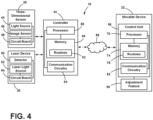
- the 3D sensor 26 generally includes a light source 44, an image sensor 46, and a circuit board 48 ( FIG. 4 ).
- the light source 44 of the 3D sensor 26 is configured to emit light in the visible or invisible spectrum into the surgical suite 14. The emitted light is generally reflected by each optical marker 18 and is subsequently detected by the image sensor 46.
- the 3D sensor 26 is configured to measure the distance between the 3D sensor 26 and each optical marker 18. Consequently, the 3D sensor 26 is configured to measure a distance between the movable device 22 or the fixed device 24 having the optical markers 18 and the 3D sensor 26 based on a time difference between the emission of light and the return of the reflected light to the 3D sensor 26.
- the 3D sensor 26 may use any practicable method of determining the distance between the 3D sensor 26 and the movable device 22 or the fixed device 24, such as, for example, timed pulses of light, phase shifts of the reflected light, or any combination thereof.
- the locating system 10 may use time-of-flight calculations generally associated with laser tracking devices.
- Such devices calculate distance based on time-of-flight and position based on the angular orientation or rotational and elevation axes that identify the projection line of the laser.
- the locating system 10 may be configured as an optical vision system that uses the parallax effect of stereoscopic cameras to determine position and depth.
- the light source 44 of the 3D sensor 26 may be any type of light source.
- the 3D sensor 26 may include a laser light or a light-emitting diode (LED).
- the 3D sensor 26 is configured to emit infrared light (e.g., having a wavelength in a range between about 700 nm and about 1 mm), near-infrared light (e.g., having a wavelength in a range between about 700 nm and about 940 nm), or a combination thereof.
- the 3D sensor 26 may be a time-of-flight camera.
- the 3D sensor 26 is configured to determine a distance between the 3D sensor 26 and the movable device 22 based on the difference in time between the emission of light from the light source 44 and the reception of reflected light back to the image sensor 46 of the 3D sensor 26. More specifically, the time between the initiation of the light by the light source 44 of the 3D sensor 26 and the reception of the reflected light received by the image sensor 46 is indicative of the distance between the 3D sensor 26 and the movable device 22 or the fixed device 24.
- the distance and position determined by the 3D sensor 26 may be communicated to the controller 34 as the initial position data.
- the 3D sensor 26 may continue to obtain the initial position data of the movable devices 22 as the movable devices 22 translate along the movement path 36 or the adjustment path 38 to dynamically calibrate and update the position of the movable devices 22.
- the 3D sensor 26 may also be configured to obtain identification data regarding the type of movable device 22 or fixed device 24 based on the arrangement or pattern of the optical markers 18. Accordingly, the locating system 10 may recognize the type of movable devices 22 or fixed devices 24 within the surgical suite 14, as well as the position of each device 22, 24.
- the optical markers 18 may be arranged in a specific pattern that is representative of a particular code that corresponds to the type of device 22, 24 registered or stored within the controller 34. Additionally or alternatively, the optical markers 18 may be arranged to reflect the light emitted from the 3D sensor 26 in a specific manner or have other distinctive properties that the locating system 10 recognizes.
- the 3D sensor 26 may obtain the identification data relating to the type of device 22, 24 and communicate the identification data to the controller 34. Recognizing the type of device or structure 22, 24 may be advantageous for the locating system 10 to determine the exact position and arrangement of the movable devices 22 and the fixed devices 24 within the surgical suite 14, as well as determine if the detected devices 22, 24 are movable or fixed
- the laser device 30 of the locating assembly 42 is configured to obtain confirmation or subsequent position data of each optical marker 18 disposed on the movable devices 22.
- the laser device 30 may be used by the locating system 10 to determine a more precise and/or more accurate position of the optical markers 18 relative to the initial position determined by the 3D sensor 26.
- the accuracy of the laser device 30 may be proportional to the distance between the laser device 30 and the optical markers 18.
- the laser device 30 may provide position accuracies of approximately 0.1 mm/m. Accordingly, the laser device 30 may confirm and enhance the accuracy of the initial position data obtained by the 3D sensor 26.
- the laser device 30 may detect each optical marker 18 using, for example, triangulation, pulse modulation, or a combination thereof. Angle calculations may be utilized to determine the distance between the laser device 30 and each optical marker 18.
- the laser device 30 may include an imager (e.g., a complementary metal-oxide-semiconductor or a charge-coupled device) or a detector 50 (e.g., a position sensitive detector), as well as a laser light source 52 and a circuit board 54 ( FIG. 4 ).
- the laser light source 52 generally emits infrared and/or near-infrared light.
- the laser light source 52 may emit light into the surgical suite 14 and reflected light from the optical markers 18 may be received through focusing optics and directed into the detector 50 of the laser device 30. As the movable devices 22 are moved within the surgical suite 14, the reflected light moves relative to the imager or detector 50, and the laser device 30 may continue to obtain the confirmation or subsequent position data as the movable devices 22 translate along the movement path 36 or the adjustment
- the initial position data obtained by the 3D sensor 26 may provide a rough estimate of the position of the optical markers 18 within the surgical suite 14.
- the initial position data may be communicated to the controller 34 and subsequently communicated to the laser device 30.
- the laser device 30 may utilize the initial position data to direct the laser light into the general area of the optical markers 18 as determined by the 3D sensor 26.
- the information obtained by the 3D sensor 26 may guide the area for the laser device 30 to scan or pinpoint a location for the laser device 30 to direct the laser light to obtain a precise position of each optical marker 18.
- the movable device 22 within the surgical suite 14 may be located by the controller 34 in an absolute or relative coordinate system. As previously discussed, the location of the movable devices 22 is calculated by the controller 34 based on positional information identified by the 3D sensor 26 in combination with the measurements from the laser device 30. In operation, the laser light emitted from the laser device 30 is reflected from the optical markers 18, which may be implemented as retro-reflective targets or similar reflective targets. The controller 34 detects or improves the calculated position of each of the movable devices 22 based on the angular orientation (azimuth axis and elevation axis) and distance readings measured by the laser device 30 in order to accurately determine the positions and/or orientations of the movable devices 22 in the surgical suite 14.
- the controller 34 detects or improves the calculated position of each of the movable devices 22 based on the angular orientation (azimuth axis and elevation axis) and distance readings measured by the laser device 30 in order to accurately determine the positions and/or orientations of the movable
- the controller 34 may identify the positions of the movable devices 22 in relation to one another, the fixed devices 24, and/or based on their associated positions within a calibrated coordinate grid and operating envelope of the surgical suite 14.
- the operating envelope may be defined or programmed into the controller 34 as a predetermined working range defined in relation to the coordinate grid.
- the light emitted by the light source 44 of the 3D sensor 26 may be scattered by bright surfaces or can produce distorted reflections based on the shape of the reflecting surface, which can affect the distance measurement obtained by the 3D sensor 26.
- the laser device 30 may be advantageous for use with highly reflective surfaces, such as metallic components, which are common within the surgical suite 14. Accordingly, the 3D sensor 26 may provide an estimated position of the optical markers 18 and provide dynamic calibration for the locating system 10, and the laser device 30 can confirm the exact positioning of each optical marker 18.
- the laser device 30 may obtain subsequent position data of the optical markers 18, which may be utilized to confirm the position of the movable devices 22 or the fixed devices 24 within the surgical suite 14. Additionally, the laser device 30 may be configured to project information 56 onto a surface within the surgical suite 14. The surface may be any surface within the surgical suite 14, such as, for example, a wall, a floor space, a whiteboard, or a removable or permanent feature for displaying data. The laser device 30 may project the information 56 on any surface with spatial alignment and without substantial distortion of the information 56. The information 56 can be or include any information or data that may be useful within the surgical suite 14 or for a medical procedure.
- the projected information 56 may be data about the movable devices 22 or the fixed devices 24 (e.g., device data, type of device data, etc.), information about the movement path 36 or the adjustment path 38 (e.g., device movement data, obstruction data, etc.), information 56 output from the movable devices 22 or the fixed devices 24 (e.g., sensed patient data, device position data, etc.), information 56 about the patient (e.g., stored patient data, patient record data, etc.), or any other information 56.
- Different types of information 56 may also be projected and displayed simultaneously, as illustrated in FIG. 3 .
- the information 56 may be displayed as a static image or a moving image.
- the laser device 30 may operate to obtain the subsequent position data of the optical markers 18 independently of and simultaneously with the projection of the information 56.
- the locating system 10 includes the controller 34, which includes a processor 58, a memory 60, and other control circuitry. Instructions or routines 62 are stored within the memory 60 and executable by the processor 58.
- the controller 34 may include at least one routine 62 that relates to receiving the initial position data from the 3D sensor 26 and determining an initial position of each optical marker 18 ( FIG. 1 ) based on the initial position data.
- the controller 34 may include at least one routine 62 that relates to receiving the subsequent position data from the laser device 30 and confirming the position of each optical marker 18 based on the subsequent position data. Additionally or alternatively, the controller 34 may include at least one routine 62 related to adjusting the laser device 30 in response to the initial position data to emit the light toward the general position of the optical markers 18.
- the controller 34 may store information regarding registered movable devices 22 or fixed devices 24 in the memory 60.
- the controller 34 may include at least one routine 62 configured to evaluate the pattern or code of the optical markers 18 and recognize the type of device or structure 22, 24 using the stored registered movable devices 22 and fixed devices 24.
- the controller 34 may store physical characteristics, including footprint, volume, geometry, etc. of each registered device or structure 22, 24.
- the controller 34 may also store information within the memory 60 relating to the geometry of the surgical suite 14, as well as information regarding the position of the fixed devices or structures 24 within the surgical suite 14 that may act as obstacles. Clearance or interference zones for each to the registered devices or structures 22, 24 that identify the locations obstructed or occupied by each of the devices 22, 24 relative to the optical markers 18 may be programmed into the controller 34. These parameters may be accessed with the identification data.
- the position of each movable device 22 may be obtained through the initial position data obtained by the 3D sensor 26 and enhanced or verified with the subsequent position data obtained by the laser device 30. Additionally or alternatively, as a safety redundancy or a collision prevention protocol, the position of the fixed devices or structure 24 may be verified with the initial position data obtained by the 3D sensor 26 and/or verified with the subsequent position data obtained by the laser device 30. While the position and physical characteristics of the fixed devices 24 are generally stored within the memory 60 of the controller 34, the position or physical characteristic may be confirmed as part of a protocol before a movable device 22 is translated along the movement path 36 or the adjustment path 38.
- the controller 34 may include communication circuitry 64 to allow the controller 34 of the locating system 10 to communicate with one or more of the movable devices 22.
- One, some, or all of the movable devices 22 within the surgical suite 14 may include a control unit 66 that has a processor 70, a memory 74, and other control circuitry. Instructions or routines 78 are stored in the memory 74 and executable by the processor 70.
- the movable devices 22 may include communication circuitry 82 to allow communication with the controller 34.
- the controller 34 is generally configured for gathering inputs from the 3D sensor 26 and the laser device 30, processing the inputs, and generating an output response to the input.
- the controller 34 may send a signal to the movable device 22 to control the movement of the movable device 22 within the surgical suite 14.
- the controller 34 and the control unit 66 disclosed herein may include various types of control circuitry, digital or analog, and may include the processors 58, 70, a microcontroller, an application specific circuit (ASIC), or other circuitry configured to perform the various input or output, control, analysis, or other functions described herein.
- the memories 60, 74 described herein may be implemented in a variety of volatile and nonvolatile memory formats.
- the routines 62, 78 include operating instructions to enable various methods and functions described herein.
- the controller 34 and the control unit 66 are communicatively coupled with one another to establish a communication interface 86 between the locating system 10 and each movable device 22.
- the controller 34 may also be configured to communicate with remote servers (e.g., cloud servers, Internet-connected databases, computers, etc.) via the communication interface 86.
- the communication interface 86 may be a network, which may be one or more various communication mechanisms, including any combination of wired (e.g., cable and fiber) and/or wireless communications and any network topology or topologies.
- Exemplary networks include wireless communication networks, such as, for example, a Wi-Fi transceiver, an IrDA transceiver, an RFID transceiver, etc.
- the communication interface 86 may be implemented via one or more direct or indirect nonhierarchical communication protocols, including but not limited to, Bluetooth ® , Bluetooth ® low energy (BLE), Thread, Ultra-Wideband, Z-wave, ZigBee, etc.
- the controller 34 and the control unit 66 communicate via a Bluetooth ® device
- the movable device 22 and the locating system 10 may be linked or synchronized. It is generally contemplated that the locating system 10 may be associated or synced with any number of movable devices 22.
- Each of the controller 34 and the control unit 66 may include circuitry configured for bidirectional wireless communication.
- the locating system 10 may detect a position of each movable device 22 and fixed device 24 within the surgical suite 14, recognize the type of movable device 22 and fixed device 24, and control movement of at least one of the movable devices 22.
- the 3D sensor 26 may determine the distance between the 3D sensor 26 and each of the movable devices 22 using each optical marker 18 ( FIG. 1 ), as well as a rough position of each optical marker 18.
- the laser device 30 may confirm the distance between each of the movable devices 22 and the laser device 30 using each optical marker 18. Accordingly, using the 3D sensor 26 and the laser device 30, the locating system 10 may detect the precise position of each movable device 22 within the surgical suite 14.
- the locating system 10 may independently or simultaneously determine the type of devices or structures 22, 24 within the surgical suite 14.
- the 3D sensor 26 may obtain identification data relating to the type of movable device 22 based on the arrangement of the optical markers 18. It is contemplated that the optical markers 18 may have different properties that can be detected by the 3D sensor 26 or the controller 34 indicative of the type of movable device 22 or fixed device 24.
- the controller 34 may send a signal to the control unit 66 of each movable device 22 to be moved. It is contemplated that one, several, or all of the devices 24 within the surgical suite 14 may include the control unit 66 to directly communicate with the controller 34. Alternatively, the fixed devices 24 may be free of direct communication with the controller 34, while the movable devices 22 may include the control unit 66 for communicating with the controller 34. As previously noted, the movable devices 22 may be freely movable about the surgical suite 14 (e.g., movable between different physical positions) along the movement path 36. Additionally or alternatively, the movable devices 22 may also have adjustable characteristics (e.g., height, tilt, rotation, etc.) and may move along the adjustment path 38 between different conditions or states. It is contemplated that the movable medical devices 22 may be manually or automatically movable. Each of the movement path 36 and the adjustment path 38 may be determined to avoid collisions with other movable devices 22 and fixed devices 24 within the surgical suite 14.
- the controller 34 may direct the movable device 22 to move along the adjustment path 38 to a new setting or state in a manner that avoids collisions with other movable devices 22 and the fixed devices 24. As such, some or all of the movable devices 22 within the surgical suite 14 may be automatically moved within the surgical suite 14. It is also contemplated that the control unit 66 of the movable device 22 may determine the movement path 36 or the adjustment path 38 based on information received from the controller 34. Accordingly, the signal from the controller 34 may operate as a movement release signal to activate independent movement of the movable device 22.
- the controller 34 may determine the position and orientation of each movable device 22 and fixed device 24 within the surgical suite 14. The precise orientation of the devices 22, 24 may be determined using at least one of the position of the optical markers 18 as well as stored information about the devices 22, 24. Using other sensed or stored information about the surgical suite, the controller 34 is configured to determine the movement path 36 or the adjustment path 38 to move or adjust the movable devices 22 based on a selected triggering event.
- the selected triggering event may be a user input, an event (e.g., overhead light activation or caregiver log-in), etc.
- the controller 34 may store the subsequent position for each device 22 that corresponds with the triggering event.
- the controller 34 is configured to determine or map the movement path 36 or the adjustment path 38 to adjust the movable device 22 to the selected subsequent position or orientation.
- the controller 34 obtains the position information of the various movable and fixed devices 22, 24 within the surgical suite 14.
- the controller 34 determines an appropriate movement path 36 or adjustment path 38 that avoids other devices 22, 24 within the surgical suite 14.
- the controller 34 may then send a signal to the control unit 66 of the movable device 22, which consequently activates the adjustment feature 90 to move the movable device 22.
- optical markers 18 may be included on surfaces of the surgical suite 14 (e.g., walls) to verify stored information of the surgical suite. Additionally or alternatively, it is contemplated that the medical professionals in the surgical suite 14 may wear or otherwise have optical markers 18 that can be sensed by the locating system 10. Such configurations may be advantageous for moving the movable devices 24 around the medical professionals.
- a method 100 of adjusting the movable devices 22 in the surgical suite 14 includes step 102 of activating the locating system 10.
- the locating assembly 42 may be activated in response to the triggering event.
- the locating assembly 42 may be activated through an automatic or automated process or through a manual input.
- the triggering event may indicate the movable devices 22 to be moved and the subsequent or end position of the movable device 22.
- the controller 34 may also detect the type of additional devices in the surgical suite, including the fixed devices 24 and other movable devices 22 (e.g., those not selected to be moved), using the 3D sensor 26 and the additional optical markers 18 coupled to the additional devices. The controller 34 may then correlate the type of device 22, 24 with stored characteristics. For example, when the controller 34 determines that the fixed device 24 is the countertop, the controller 34 may recognize a size, shape, interference zone, position in the surgical suite 14, etc. Using the specific patterns of the optical markers 18, the controller 34 may determine that the device 22, 24 is fixed or movable. Accordingly, using the arrangement of the optical markers 18, the locating system 10 may determine whether the device 22, 24 is movable or fixed and the exact type or category of device 22, 24, as well as correlate stored information with the detected type of device 22, 24.
- the controller 34 may also detect the type of additional devices in the surgical suite, including the fixed devices 24 and other movable devices 22 (e.g., those not selected to be moved), using the 3D sensor 26 and the additional optical markers 18 coupled to the
- step 108 the position of each optical marker 18 and, consequently, the movable device 22 are detected using the 3D sensor 26.
- the 3D sensor 26 may be configured to emit light and determine the distance between the 3D sensor 26 and each optical marker 18 based on the difference in time between when the light is emitted from the 3D sensor 26 and when the reflected light is received by the 3D sensor 26.
- the initial position data are communicated to the controller 34. It is contemplated that the 3D sensor 26 may continually obtain initial position data for each optical marker 18, may periodically obtain initial position data, or may obtain initial position data in response to a user command.
- elements shown as integrally formed may be constructed of multiple parts, or elements shown as multiple parts may be integrally formed, the operation of the interfaces may be reversed or otherwise varied, the length or width of the structures and/or members or connector or other elements of the system may be varied, the nature or number of adjustment positions provided between the elements may be varied.
- the elements and/or assemblies of the system may be constructed from any of a wide variety of materials that provide sufficient strength or durability, in any of a wide variety of colors, textures, and combinations.
- the exemplary structures and processes disclosed herein are for illustrative purposes and are not to be construed as limiting.
Landscapes
- Engineering & Computer Science (AREA)
- Health & Medical Sciences (AREA)
- Biomedical Technology (AREA)
- Public Health (AREA)
- Medical Informatics (AREA)
- General Health & Medical Sciences (AREA)
- Business, Economics & Management (AREA)
- Life Sciences & Earth Sciences (AREA)
- Surgery (AREA)
- General Business, Economics & Management (AREA)
- Primary Health Care (AREA)
- Epidemiology (AREA)
- Physics & Mathematics (AREA)
- General Physics & Mathematics (AREA)
- Robotics (AREA)
- Animal Behavior & Ethology (AREA)
- Molecular Biology (AREA)
- Heart & Thoracic Surgery (AREA)
- Veterinary Medicine (AREA)
- Nuclear Medicine, Radiotherapy & Molecular Imaging (AREA)
- Computer Vision & Pattern Recognition (AREA)
- Theoretical Computer Science (AREA)
- Human Computer Interaction (AREA)
- Manufacturing & Machinery (AREA)
- Automation & Control Theory (AREA)
- Length Measuring Devices By Optical Means (AREA)
Description
- The present disclosure generally relates to a locating system for medical devices in a surgical suite.
-
US 2019/321126 discloses systems, methods and software for aiding in positioning of a camera relative to objects in a surgical environment. The camera has a 3D field of view and senses positions of the objects in the field of view. A controller is coupled to the camera and defines a first zone and a second zone within the field of view. Each zone defines a range of acceptable positions for one of the objects relative to a position of the camera. The controller receives the position of the objects. A graphical user interface displays image representations of: the field of view, the first zone relative to the field of view, the second zone relative to the field of view, the position of one object relative to the first zone, and the position of another object relative to the second zone. A laser range finder is configured to provide a primary or supplemental aid in positioning of the camera. -
WO 2017/147596 discloses a system and process for dynamically positioning or repositioning a robot in a surgical context based on workspace and task requirements, manipulator requirements, or user preferences to execute a surgical plan. The system and method accurately determines and indicates an optimal position for a robot with respect to a patient's anatomy before or during a surgical procedure. Optimal positions for a robot are intuitively indicated to a user. This document discloses an example where a robot base is equipped with laser distance measurement sensors (LIDARS) and/or cameras to utilize machine vision to position the robot. -
US 2020/019231 discloses a device using a hybrid pose tracking system, whereby the hybrid pose tracking system includes both an EM pose tracking system and a secondary pose tracking system, such as a line-of-sight pose tracking system. The hybrid pose tracking system collects EM pose data from the EM tracking system indicating a relative pose between a transmitter and a receiver, and further collects from the secondary tracking system secondary pose data that is also indicative of the pose of either the transmitter or the receiver. The hybrid pose tracking system calculates a weighted combination (e.g., a weighted sum) of the EM pose data and the secondary pose data to generate a final pose for the device. - According to one embodiment of the present invention and as defined in claim 1, a locating system for a surgical suite includes a medical device and optical markers coupled to the medical device. A sensor is configured to obtain initial position data of the optical markers. A laser device is configured to obtain subsequent position data of the optical markers. A controller is configured to receive the initial position data from the sensor and the subsequent position data from the laser device. The controller is configured to determine a position of the medical device within said surgical suite and recognize a type of the medical device in response to the optical markers.
- According to another embodiment of the present invention and as defined in claim 15, a method of detecting and registering a device within a surgical suite includes detecting a type of a medical device within said surgical suite and determining whether the medical device is a fixed device or a movable device with a controller. Initial position data of the medical device is detected using a sensor and the plurality of optical markers coupled to the medical device. Subsequent position data of the plurality of optical markers coupled to the medical device is detected using a laser device. At least one of a movement path and an adjustment path for the medical device is determined with the controller for moving the medical device with an adjustment feature when it is determined that the medical device is a movable device.
- The invention will now be further described by way of example with reference to the accompanying drawings, in which:
-
FIG. 1 is a schematic view of a surgical suite that includes a locating system, according to the present disclosure; -
FIG. 2 is a schematic view of the surgical suite ofFIG. 1 with medical devices located in different positions; -
FIG. 3 is a schematic view of a locating system for a surgical suite, according to the present disclosure; -
FIG. 4 is a box diagram of a locating system in communication with a medical device, according to the present disclosure; -
FIG. 5 is a flow diagram of a locating system for controlling movement of a medical device within a surgical suite, according to the present disclosure; and -
FIG. 6 is a flow diagram of a method for adjusting a medical device along a movement path or an adjustment path, according to the present disclosure. - The present illustrated embodiments reside primarily in combinations of method steps and apparatus components related to a locating system for medical devices. Accordingly, the apparatus components and method steps have been represented, where appropriate, by conventional symbols in the drawings, showing only those specific details that are pertinent to understanding the embodiments of the present disclosure so as not to obscure the disclosure with details that will be readily apparent to those of ordinary skill in the art having the benefit of the description herein. Further, like numerals in the description and drawings represent like elements.
- For purposes of description herein, the terms "upper," "lower," "right," "left," "rear," "front," "vertical," "horizontal," and derivatives thereof, shall relate to the disclosure as oriented in
FIG. 1 . Unless stated otherwise, the term "front" shall refer to a surface closest to an intended viewer, and the term "rear" shall refer to a surface furthest from the intended viewer. However, it is to be understood that the disclosure may assume various alternative orientations, except where expressly specified to the contrary. It is also to be understood that the specific structures and processes illustrated in the attached drawings, and described in the following specification are simply exemplary embodiments of the inventive concepts defined in the appended claims. Hence, specific dimensions and other physical characteristics relating to the embodiments disclosed herein are not to be considered as limiting, unless the claims expressly state otherwise. - The terms "including," "comprises," "comprising," or any other variation thereof, are intended to cover a non-exclusive inclusion, such that a process, method, article, or apparatus that comprises a list of elements does not include only those elements but may include other elements not expressly listed or inherent to such process, method, article, or apparatus. An element preceded by "comprises a ... " does not, without more constraints, preclude the existence of additional identical elements in the process, method, article, or apparatus that comprises the element.
- Referring to
FIGS. 1-6 ,reference numeral 10 generally designates a locating system for asurgical suite 14.Optical markers 18 are coupled to a medical device, which may be amovable device 22 or a fixed device orstructure 24. A three-dimensional (3D)sensor 26 is configured to obtain initial position data of theoptical markers 18. Alaser device 30 is configured to obtain confirmation or subsequent position data of theoptical markers 18. Acontroller 34 receives the initial position data from the3D sensor 26 and the subsequent position data from thelaser device 30. Thecontroller 34 is configured to determine a position of themovable device 22 within thesurgical suite 14 and to control movement of themovable device 22 in response to the initial position data and the subsequent position data. Thecontroller 34 is also configured to recognize a type of themovable device 22 and thefixed device 24 in response to theoptical markers 18. - Referring to
FIGS. 1 and 2 , the locatingsystem 10 is illustrated within thesurgical suite 14 but may be used in other medical settings and/or environments. The locatingsystem 10 is generally configured to determine a position of themovable device 22 within thesurgical suite 14 and control the movement of themovable device 22. Thesurgical suite 14 may include one or moremovable devices 22 and fixed devices orstructure 24 at any given time. The medical devices andstructures surgical suite 14, used for medical procedures, or otherwise used within a medical environment. - As illustrated in
FIG. 1 , thesurgical suite 14 includes a counter adjacent to one wall, which is an example of onefixed structure 24 within thesurgical suite 14. The illustratedsurgical suite 14 also includes two examples of different types ofmovable devices 22. The exemplary movable devices illustrated inFIG. 1 are a surgical table and a C-arm X-ray machine. The surgical table may be freely moved about thesurgical suite 14 from one physical position to another along amovement path 36. The C-arm X-ray machine is fixedly coupled to aceiling 40 within thesurgical suite 14 and therefore may not freely move between different physical locations within the surgical suite 14 (e.g., left to right or front to back). However, the C-arm X-ray machine may be freely adjusted, such as in height or rotation, while remaining in the fixed location. Accordingly, the C-arm X-ray machine is generally movable along anadjustment path 38. - Some
movable devices 22, for example the surgical table, may move along themovement path 36 and theadjustment path 38. Themovement path 36 generally defines a space between two distinct or discrete physical locations (e.g., moving horizontally about the surgical suite 14). Theadjustment path 38 generally defines a change between physical states, conditions, or characteristics at a single physical location or between physical locations as themovable device 22 translates along themovement path 36. Other examples of the medical device orstructure - The
optical markers 18 are generally coupled to an outer surface of eachmovable device 22 and fixed device orstructure 24 within thesurgical suite 14. Theoptical markers 18 may be any practicable feature that can be recognized by the locatingsystem 10. Theoptical markers 18 enable optical registration and measurement of eachmovable device 22. The number ofoptical markers 18 may differ based on the size, geometry, type of themovable device 22 or the fixeddevice 24, the static or dynamic nature of themovable device 22 or the fixeddevice 24, whether themovable device 22 translates along themovement path 36, or whether themovable device 22 is moved along theadjustment path 38, as well as various aspects of themovable device 22. For example, as illustrated inFIG. 1 , the fixed C-arm X-ray machine includes threeoptical markers 18, the surgical table includes sixoptical markers 18, and the counter includes fouroptical markers 18. The number ofoptical markers 18 on the illustrated devices andstructures optical markers 18 may be coupled to each device orstructure - As illustrated in
FIG. 1 , a locatingassembly 42 is coupled to theceiling 40 within thesurgical suite 14. The locatingassembly 42 may include the3D sensor 26, thelaser device 30, and thecontroller 34. Positioning the locatingassembly 42 adjacent to or on theceiling 40 may increase the area within thesurgical suite 14 that the3D sensor 26 and thelaser device 30 can obtain data from and consequently increase the number ofmovable devices 22 that the locatingsystem 10 can control. However, it is contemplated that the locatingassembly 42 may be disposed in any practicable location or in multiple locations within thesurgical suite 14. Each of the3D sensor 26, thelaser device 30, and thecontroller 34 may be included in a single component, or alternatively, may be separate components within thesurgical suite 14. - The locating
system 10 is configured to detect the position of themovable devices 22 and the fixeddevices 24 within thesurgical suite 14 and recognize each type of device orstructure 3D sensor 26 of the locatingsystem 10 is configured to obtain the initial position data of theoptical markers 18. The3D sensor 26 measures a distance between the3D sensor 26 and theoptical markers 18. The3D sensor 26 generally includes alight source 44, animage sensor 46, and a circuit board 48 (FIG. 4 ). Thelight source 44 of the3D sensor 26 is configured to emit light in the visible or invisible spectrum into thesurgical suite 14. The emitted light is generally reflected by eachoptical marker 18 and is subsequently detected by theimage sensor 46. - The
3D sensor 26 is configured to measure the distance between the3D sensor 26 and eachoptical marker 18. Consequently, the3D sensor 26 is configured to measure a distance between themovable device 22 or the fixeddevice 24 having theoptical markers 18 and the3D sensor 26 based on a time difference between the emission of light and the return of the reflected light to the3D sensor 26. The3D sensor 26 may use any practicable method of determining the distance between the3D sensor 26 and themovable device 22 or the fixeddevice 24, such as, for example, timed pulses of light, phase shifts of the reflected light, or any combination thereof. For example, the locatingsystem 10 may use time-of-flight calculations generally associated with laser tracking devices. Such devices calculate distance based on time-of-flight and position based on the angular orientation or rotational and elevation axes that identify the projection line of the laser. In another example, the locatingsystem 10 may be configured as an optical vision system that uses the parallax effect of stereoscopic cameras to determine position and depth. - The
light source 44 of the3D sensor 26 may be any type of light source. In specific non-limiting examples, the3D sensor 26 may include a laser light or a light-emitting diode (LED). Generally, the3D sensor 26 is configured to emit infrared light (e.g., having a wavelength in a range between about 700 nm and about 1 mm), near-infrared light (e.g., having a wavelength in a range between about 700 nm and about 940 nm), or a combination thereof. - In non-limiting examples, the
3D sensor 26 may be a time-of-flight camera. In such examples, the3D sensor 26 is configured to determine a distance between the3D sensor 26 and themovable device 22 based on the difference in time between the emission of light from thelight source 44 and the reception of reflected light back to theimage sensor 46 of the3D sensor 26. More specifically, the time between the initiation of the light by thelight source 44 of the3D sensor 26 and the reception of the reflected light received by theimage sensor 46 is indicative of the distance between the3D sensor 26 and themovable device 22 or the fixeddevice 24. The distance and position determined by the3D sensor 26 may be communicated to thecontroller 34 as the initial position data. The3D sensor 26 may continue to obtain the initial position data of themovable devices 22 as themovable devices 22 translate along themovement path 36 or theadjustment path 38 to dynamically calibrate and update the position of themovable devices 22. - The
3D sensor 26 may also be configured to obtain identification data regarding the type ofmovable device 22 or fixeddevice 24 based on the arrangement or pattern of theoptical markers 18. Accordingly, the locatingsystem 10 may recognize the type ofmovable devices 22 or fixeddevices 24 within thesurgical suite 14, as well as the position of eachdevice optical markers 18 may be arranged in a specific pattern that is representative of a particular code that corresponds to the type ofdevice controller 34. Additionally or alternatively, theoptical markers 18 may be arranged to reflect the light emitted from the3D sensor 26 in a specific manner or have other distinctive properties that the locatingsystem 10 recognizes. The3D sensor 26 may obtain the identification data relating to the type ofdevice controller 34. Recognizing the type of device orstructure system 10 to determine the exact position and arrangement of themovable devices 22 and the fixeddevices 24 within thesurgical suite 14, as well as determine if the detecteddevices - Referring still to
FIGS. 1 and 2 , thelaser device 30 of the locatingassembly 42 is configured to obtain confirmation or subsequent position data of eachoptical marker 18 disposed on themovable devices 22. Thelaser device 30 may be used by the locatingsystem 10 to determine a more precise and/or more accurate position of theoptical markers 18 relative to the initial position determined by the3D sensor 26. The accuracy of thelaser device 30 may be proportional to the distance between thelaser device 30 and theoptical markers 18. In a specific non-limiting example, thelaser device 30 may provide position accuracies of approximately 0.1 mm/m. Accordingly, thelaser device 30 may confirm and enhance the accuracy of the initial position data obtained by the3D sensor 26. - The
laser device 30 may detect eachoptical marker 18 using, for example, triangulation, pulse modulation, or a combination thereof. Angle calculations may be utilized to determine the distance between thelaser device 30 and eachoptical marker 18. Thelaser device 30 may include an imager (e.g., a complementary metal-oxide-semiconductor or a charge-coupled device) or a detector 50 (e.g., a position sensitive detector), as well as alaser light source 52 and a circuit board 54 (FIG. 4 ). Thelaser light source 52 generally emits infrared and/or near-infrared light. Thelaser light source 52 may emit light into thesurgical suite 14 and reflected light from theoptical markers 18 may be received through focusing optics and directed into thedetector 50 of thelaser device 30. As themovable devices 22 are moved within thesurgical suite 14, the reflected light moves relative to the imager ordetector 50, and thelaser device 30 may continue to obtain the confirmation or subsequent position data as themovable devices 22 translate along themovement path 36 or theadjustment path 38. - The initial position data obtained by the
3D sensor 26 may provide a rough estimate of the position of theoptical markers 18 within thesurgical suite 14. The initial position data may be communicated to thecontroller 34 and subsequently communicated to thelaser device 30. Thelaser device 30 may utilize the initial position data to direct the laser light into the general area of theoptical markers 18 as determined by the3D sensor 26. The information obtained by the3D sensor 26 may guide the area for thelaser device 30 to scan or pinpoint a location for thelaser device 30 to direct the laser light to obtain a precise position of eachoptical marker 18. - The
movable device 22 within thesurgical suite 14 may be located by thecontroller 34 in an absolute or relative coordinate system. As previously discussed, the location of themovable devices 22 is calculated by thecontroller 34 based on positional information identified by the3D sensor 26 in combination with the measurements from thelaser device 30. In operation, the laser light emitted from thelaser device 30 is reflected from theoptical markers 18, which may be implemented as retro-reflective targets or similar reflective targets. Thecontroller 34 detects or improves the calculated position of each of themovable devices 22 based on the angular orientation (azimuth axis and elevation axis) and distance readings measured by thelaser device 30 in order to accurately determine the positions and/or orientations of themovable devices 22 in thesurgical suite 14. Thecontroller 34 may identify the positions of themovable devices 22 in relation to one another, the fixeddevices 24, and/or based on their associated positions within a calibrated coordinate grid and operating envelope of thesurgical suite 14. The operating envelope may be defined or programmed into thecontroller 34 as a predetermined working range defined in relation to the coordinate grid. - According to various aspects, the light emitted by the
light source 44 of the3D sensor 26 may be scattered by bright surfaces or can produce distorted reflections based on the shape of the reflecting surface, which can affect the distance measurement obtained by the3D sensor 26. Thelaser device 30 may be advantageous for use with highly reflective surfaces, such as metallic components, which are common within thesurgical suite 14. Accordingly, the3D sensor 26 may provide an estimated position of theoptical markers 18 and provide dynamic calibration for the locatingsystem 10, and thelaser device 30 can confirm the exact positioning of eachoptical marker 18. - Referring to
FIG. 3 , as previously noted, thelaser device 30 may obtain subsequent position data of theoptical markers 18, which may be utilized to confirm the position of themovable devices 22 or the fixeddevices 24 within thesurgical suite 14. Additionally, thelaser device 30 may be configured to projectinformation 56 onto a surface within thesurgical suite 14. The surface may be any surface within thesurgical suite 14, such as, for example, a wall, a floor space, a whiteboard, or a removable or permanent feature for displaying data. Thelaser device 30 may project theinformation 56 on any surface with spatial alignment and without substantial distortion of theinformation 56. Theinformation 56 can be or include any information or data that may be useful within thesurgical suite 14 or for a medical procedure. - For example, the projected
information 56 may be data about themovable devices 22 or the fixed devices 24 (e.g., device data, type of device data, etc.), information about themovement path 36 or the adjustment path 38 (e.g., device movement data, obstruction data, etc.),information 56 output from themovable devices 22 or the fixed devices 24 (e.g., sensed patient data, device position data, etc.),information 56 about the patient (e.g., stored patient data, patient record data, etc.), or anyother information 56. Different types ofinformation 56 may also be projected and displayed simultaneously, as illustrated inFIG. 3 . Theinformation 56 may be displayed as a static image or a moving image. Thelaser device 30 may operate to obtain the subsequent position data of theoptical markers 18 independently of and simultaneously with the projection of theinformation 56. - Referring to
FIG. 4 , the locatingsystem 10 includes thecontroller 34, which includes aprocessor 58, amemory 60, and other control circuitry. Instructions orroutines 62 are stored within thememory 60 and executable by theprocessor 58. Thecontroller 34 may include at least one routine 62 that relates to receiving the initial position data from the3D sensor 26 and determining an initial position of each optical marker 18 (FIG. 1 ) based on the initial position data. Similarly, thecontroller 34 may include at least one routine 62 that relates to receiving the subsequent position data from thelaser device 30 and confirming the position of eachoptical marker 18 based on the subsequent position data. Additionally or alternatively, thecontroller 34 may include at least one routine 62 related to adjusting thelaser device 30 in response to the initial position data to emit the light toward the general position of theoptical markers 18. - According to various aspects, the
controller 34 may store information regarding registeredmovable devices 22 or fixeddevices 24 in thememory 60. Thecontroller 34 may include at least one routine 62 configured to evaluate the pattern or code of theoptical markers 18 and recognize the type of device orstructure movable devices 22 and fixeddevices 24. Thecontroller 34 may store physical characteristics, including footprint, volume, geometry, etc. of each registered device orstructure controller 34 may also store information within thememory 60 relating to the geometry of thesurgical suite 14, as well as information regarding the position of the fixed devices orstructures 24 within thesurgical suite 14 that may act as obstacles. Clearance or interference zones for each to the registered devices orstructures devices optical markers 18 may be programmed into thecontroller 34. These parameters may be accessed with the identification data. - As previously noted, the position of each
movable device 22 may be obtained through the initial position data obtained by the3D sensor 26 and enhanced or verified with the subsequent position data obtained by thelaser device 30. Additionally or alternatively, as a safety redundancy or a collision prevention protocol, the position of the fixed devices orstructure 24 may be verified with the initial position data obtained by the3D sensor 26 and/or verified with the subsequent position data obtained by thelaser device 30. While the position and physical characteristics of the fixeddevices 24 are generally stored within thememory 60 of thecontroller 34, the position or physical characteristic may be confirmed as part of a protocol before amovable device 22 is translated along themovement path 36 or theadjustment path 38. - The
controller 34 may includecommunication circuitry 64 to allow thecontroller 34 of the locatingsystem 10 to communicate with one or more of themovable devices 22. One, some, or all of themovable devices 22 within thesurgical suite 14 may include acontrol unit 66 that has aprocessor 70, amemory 74, and other control circuitry. Instructions orroutines 78 are stored in thememory 74 and executable by theprocessor 70. Themovable devices 22 may includecommunication circuitry 82 to allow communication with thecontroller 34. Thecontroller 34 is generally configured for gathering inputs from the3D sensor 26 and thelaser device 30, processing the inputs, and generating an output response to the input. Thecontroller 34 may send a signal to themovable device 22 to control the movement of themovable device 22 within thesurgical suite 14. - The
controller 34 and thecontrol unit 66 disclosed herein may include various types of control circuitry, digital or analog, and may include theprocessors memories routines - The
controller 34 and thecontrol unit 66 are communicatively coupled with one another to establish acommunication interface 86 between the locatingsystem 10 and eachmovable device 22. Thecontroller 34 may also be configured to communicate with remote servers (e.g., cloud servers, Internet-connected databases, computers, etc.) via thecommunication interface 86. Thecommunication interface 86 may be a network, which may be one or more various communication mechanisms, including any combination of wired (e.g., cable and fiber) and/or wireless communications and any network topology or topologies. - Exemplary networks include wireless communication networks, such as, for example, a Wi-Fi transceiver, an IrDA transceiver, an RFID transceiver, etc. Additionally or alternatively, the
communication interface 86 may be implemented via one or more direct or indirect nonhierarchical communication protocols, including but not limited to, Bluetooth®, Bluetooth® low energy (BLE), Thread, Ultra-Wideband, Z-wave, ZigBee, etc. In examples where thecontroller 34 and thecontrol unit 66 communicate via a Bluetooth® device, themovable device 22 and the locatingsystem 10 may be linked or synchronized. It is generally contemplated that the locatingsystem 10 may be associated or synced with any number ofmovable devices 22. Each of thecontroller 34 and thecontrol unit 66 may include circuitry configured for bidirectional wireless communication. - Additionally, the exemplary networks can include, but are not limited to, global system for mobile communication (GSM), general packet radio services, code division multiple access, enhanced data GSM environment, fourth generation (4G) wireless, fifth generation (5G) wireless, Wi-Fi, world interoperability for wired microwave access (WiMAX), local area networks (LAN), wide area networks (WAN), including the Internet and other data communication services. It is contemplated that the
controller 34 and thecontrol unit 66 can communicate by any suitable technology for exchanging data. By flexibly implementing thecommunication interface 86, various devices and servers may communicate with one another directly via thewireless communication interface 86 or a cellular data connection. - Referring to
FIGS. 2 ,4 , and5 , thecommunication interface 86 between thecontroller 34 of the locatingsystem 10 and thecontrol unit 66 of themovable device 22 may be used for transmission of signals to control the movement of one or more of themovable devices 22 along one or both of themovement path 36 and theadjustment path 38. Eachmovable device 22 may include anadjustment feature 90. Theadjustment feature 90 may be any assembly or system that adjusts a physical position or a characteristic of themovable device 22. Characteristics of themovable device 22 that may be adjusted may be, for example, an angle, a height, an orientation, a physical location, or any other aspect of the movable device 22 (e.g., trend, tilt, maximum stroke, etc.). - The
adjustment feature 90 may assist in translation and steering of a surgical table or other support apparatus. In a non-limiting example, theadjustment feature 90 may be a motorized wheel assembly that translates themovable device 22 along themovement path 36 to a different physical position within thesurgical suite 14. In another non-limiting example, theadjustment feature 90 may be a hydraulic or pneumatic cylinder, a motorized assembly, etc. that adjusts a height-based characteristic of themovable device 22 along theadjustment path 38. For example, theadjustment feature 90 may be a hydraulic adjustment for a surgical table or other support apparatus. Additionally or alternatively, theadjustment feature 90 may be an articulating robotic arm with one or more degrees of freedom. Other non-limiting adjustment features 90 may include gear assemblies or rail assemblies. The configuration of theadjustment feature 90 generally depends on themovable device 22. - In operation, it is contemplated that the locating
system 10 may detect a position of eachmovable device 22 and fixeddevice 24 within thesurgical suite 14, recognize the type ofmovable device 22 and fixeddevice 24, and control movement of at least one of themovable devices 22. The3D sensor 26 may determine the distance between the3D sensor 26 and each of themovable devices 22 using each optical marker 18 (FIG. 1 ), as well as a rough position of eachoptical marker 18. Thelaser device 30 may confirm the distance between each of themovable devices 22 and thelaser device 30 using eachoptical marker 18. Accordingly, using the3D sensor 26 and thelaser device 30, the locatingsystem 10 may detect the precise position of eachmovable device 22 within thesurgical suite 14. - Additionally, as previously noted, the locating
system 10 may independently or simultaneously determine the type of devices orstructures surgical suite 14. The3D sensor 26 may obtain identification data relating to the type ofmovable device 22 based on the arrangement of theoptical markers 18. It is contemplated that theoptical markers 18 may have different properties that can be detected by the3D sensor 26 or thecontroller 34 indicative of the type ofmovable device 22 or fixeddevice 24. - The
controller 34 may include at least one routine 62 that determines the position of eachmovable device 22 within thesurgical suite 14 in response to the initial and subsequent position data received. Thecontroller 34 may include stored information regarding the position of the fixeddevices 24 and physical characteristics, such as geometries, of each type ofmovable device 22 and fixeddevice 24. Using the identification data in conjunction with the initial and subsequent position data, thecontroller 34 may also determine the precise orientation of eachmovable device 22 within thesurgical suite 14. The orientation, precise position, and type of eachmovable device 22 and fixeddevice 24 may be utilized by thecontroller 34 to determine themovement path 36 or theadjustment path 38. - The
controller 34 may send a signal to thecontrol unit 66 of eachmovable device 22 to be moved. It is contemplated that one, several, or all of thedevices 24 within thesurgical suite 14 may include thecontrol unit 66 to directly communicate with thecontroller 34. Alternatively, the fixeddevices 24 may be free of direct communication with thecontroller 34, while themovable devices 22 may include thecontrol unit 66 for communicating with thecontroller 34. As previously noted, themovable devices 22 may be freely movable about the surgical suite 14 (e.g., movable between different physical positions) along themovement path 36. Additionally or alternatively, themovable devices 22 may also have adjustable characteristics (e.g., height, tilt, rotation, etc.) and may move along theadjustment path 38 between different conditions or states. It is contemplated that the movablemedical devices 22 may be manually or automatically movable. Each of themovement path 36 and theadjustment path 38 may be determined to avoid collisions with othermovable devices 22 and fixeddevices 24 within thesurgical suite 14. - The
controller 34 is configured to communicate at least one of themovement path 36 or theadjustment path 38 to themovable device 22 based on initial and subsequent position data received from the3D sensor 26 and thelaser device 30 of each recognized device or structure, the type ofmovable device 22, and the stored physical characteristics of thesurgical suite 14 and themovable device 22. Accordingly, thecontroller 34 directs themovable device 22 to a new physical position within thesurgical suite 14 while avoiding other objects (e.g.,movable devices 22 and fixed devices 24) within thesurgical suite 14. More specifically, thecontroller 34 may control the movement of themovable devices 22 in a manner that avoids collisions with other detected devices orstructures devices optical markers 18. These parameters may be accessed with the identification data. - Additionally or alternatively, the
controller 34 may direct themovable device 22 to move along theadjustment path 38 to a new setting or state in a manner that avoids collisions with othermovable devices 22 and the fixeddevices 24. As such, some or all of themovable devices 22 within thesurgical suite 14 may be automatically moved within thesurgical suite 14. It is also contemplated that thecontrol unit 66 of themovable device 22 may determine themovement path 36 or theadjustment path 38 based on information received from thecontroller 34. Accordingly, the signal from thecontroller 34 may operate as a movement release signal to activate independent movement of themovable device 22. - Using the information from the
3D sensor 26 and thelaser device 30, thecontroller 34 may determine the position and orientation of eachmovable device 22 and fixeddevice 24 within thesurgical suite 14. The precise orientation of thedevices optical markers 18 as well as stored information about thedevices controller 34 is configured to determine themovement path 36 or theadjustment path 38 to move or adjust themovable devices 22 based on a selected triggering event. The selected triggering event may be a user input, an event (e.g., overhead light activation or caregiver log-in), etc. Thecontroller 34 may store the subsequent position for eachdevice 22 that corresponds with the triggering event. - For example, the
controller 34 may store information that when the overhead light is activated in thesurgical suite 14, the support apparatus is to be positioned directly under the overhead light. If the surgical table is not in the correct position, thecontroller 34 may automatically adjust the position of the support apparatus. In another non-limiting example, the C-arm x-ray machine may be adjusted to provide imaging of the patient on the support apparatus in response to an input from a medical professional in thesurgical suite 14. The medical professional may issue a command through a user interface (e.g., a touch command, a voice command, a gesture, etc.) that is communicated to the locatingsystem 10. The locatingsystem 10 may then adjust the C-arm x-ray machine in accordance with the command. - Based on the triggering event, the
controller 34 is configured to determine or map themovement path 36 or theadjustment path 38 to adjust themovable device 22 to the selected subsequent position or orientation. Thecontroller 34 obtains the position information of the various movable and fixeddevices surgical suite 14. Using the selected subsequent or end location or position and the position and orientation ofother devices surgical suite 14, thecontroller 34 determines anappropriate movement path 36 oradjustment path 38 that avoidsother devices surgical suite 14. Thecontroller 34 may then send a signal to thecontrol unit 66 of themovable device 22, which consequently activates theadjustment feature 90 to move themovable device 22. - It is contemplated that additional
optical markers 18 may be included on surfaces of the surgical suite 14 (e.g., walls) to verify stored information of the surgical suite. Additionally or alternatively, it is contemplated that the medical professionals in thesurgical suite 14 may wear or otherwise haveoptical markers 18 that can be sensed by the locatingsystem 10. Such configurations may be advantageous for moving themovable devices 24 around the medical professionals. - Referring to
FIG. 6 , and with further reference toFIGS. 1-5 , amethod 100 of adjusting themovable devices 22 in thesurgical suite 14 includesstep 102 of activating the locatingsystem 10. The locatingassembly 42 may be activated in response to the triggering event. The locatingassembly 42 may be activated through an automatic or automated process or through a manual input. The triggering event may indicate themovable devices 22 to be moved and the subsequent or end position of themovable device 22. - In
step 104, the type ofmovable devices 22 is detected by the locatingassembly 42. The3D sensor 26 may obtain identification data regarding the type of themovable devices 22 based on the arrangement or pattern of theoptical markers 18 on the selectedmovable device 22, which may subsequently be communicated to thecontroller 34. The3D sensor 26 may be utilized to sense or detect the position or arrangement of theoptical markers 18 around thesurgical suite 14. Thecontroller 34 may include stored information in thememory 60 regarding the arrangement of theoptical markers 18, which associates specific patterns with certain types of devices or structures. Using the specific patterns, thecontroller 34 may determine that thedevice 22 is amovable device 22. - Further, in
step 104, thecontroller 34 may correlate the detected type ofdevice 22 with stored characteristics. Knowing the type ofmovable device 22 may be advantageous for ascertaining whether one ormore movement paths 36, one ormore adjustment paths 38, or both are available to themovable device 22. For example, when thecontroller 34 determines that themovable device 22 is the support apparatus, thecontroller 34 may recognize a size, shape, ability to move, ability to adjust, etc. - In
step 106, thecontroller 34 may also detect the type of additional devices in the surgical suite, including the fixeddevices 24 and other movable devices 22 (e.g., those not selected to be moved), using the3D sensor 26 and the additionaloptical markers 18 coupled to the additional devices. Thecontroller 34 may then correlate the type ofdevice controller 34 determines that the fixeddevice 24 is the countertop, thecontroller 34 may recognize a size, shape, interference zone, position in thesurgical suite 14, etc. Using the specific patterns of theoptical markers 18, thecontroller 34 may determine that thedevice optical markers 18, the locatingsystem 10 may determine whether thedevice device device - In
step 108, the position of eachoptical marker 18 and, consequently, themovable device 22 are detected using the3D sensor 26. The3D sensor 26 may be configured to emit light and determine the distance between the3D sensor 26 and eachoptical marker 18 based on the difference in time between when the light is emitted from the3D sensor 26 and when the reflected light is received by the3D sensor 26. The initial position data are communicated to thecontroller 34. It is contemplated that the3D sensor 26 may continually obtain initial position data for eachoptical marker 18, may periodically obtain initial position data, or may obtain initial position data in response to a user command. - In
step 110, thecontroller 34 may verify or confirm the position of theadditional device surgical suite 14. The locatingsystem 10 may utilize the3D sensor 26 to obtain an estimation of the position (e.g., the initial position data) of theoptical markers 18 on the fixeddevices 24 and othermovable devices 22. Thecontroller 34 may compare the sensed position of theoptical markers 18 with stored locations for eachfixed device 24. - In
step 112, the position of eachoptical marker 18 on the selectedmovable device 22 may be detected and confirmed using thelaser device 30. Thelaser device 30 may use triangulation or pulse modulation to detect a more precise or accurate position for eachoptical marker 18. The subsequent position data may be communicated to thecontroller 34. It is contemplated that thelaser device 30 may continually obtain the subsequent position data for eachoptical marker 18, may periodically obtain subsequent position data, or may obtain subsequent position data in response to a user command. - In
step 114, the subsequent position data for the additional devices, including the fixeddevices 24 and the othermovable devices 22, may be obtained with thelaser device 30. The subsequent position data may provide confirmation of the precise position and orientation of thedevices laser device 30 may be utilized to confirm or verify the position of thedevices controller 34 may compare the subsequent position data with stored information on the position of the fixeddevices 24 and theoptical markers 18 on the fixeddevices 24. - In
step 116, thecontroller 34 may calculate or determine themovement path 36, theadjustment path 38, or a combination thereof based on themovable device 22 or themovable devices 22 to be moved. Thecontroller 34 may utilize the initial and subsequent position data of thedevices surgical suite 14, as well as the position of any otheroptical markers 18 within thesurgical suite 14. Thecontroller 34 may then determine themovement path 36 or theadjustment path 38 that allows themovable device 22 to reach the subsequent position or state and avoids collisions with other detecteddevices surgical suite 14. Accordingly, thecontroller 34 is configured to determine and confirm the position of the selectedmovable device 22 as well as the additional devices in thesurgical suite 14 to provide themovement path 36 or theadjustment path 38 that is free of the additional devices. - In
step 118, themovable device 22 may be moved within thesurgical suite 14 in response to the detected position and the detected type ofmovable device 22. Thecontroller 34 may communicate a signal to themovable device 22, which may then send a corresponding signal to theadjustment feature 90. Themovable device 22 may be moved along themovement path 36 between the initial location (e.g., a first position) and a subsequent location (e.g., a second position) within thesurgical suite 14. Themovement path 36 or theadjustment path 38 may be defined by thecontroller 34 or thecontrol unit 66 and may be free of any other detected devices or structures within thesurgical suite 14. Thecontroller 34 may design themovement path 36 and theadjustment path 38 in response to a variety of detected data and stored data to avoid collisions between themovable device 22 and other devices andstructures surgical suite 14. It is contemplated that themovable device 22 may be moved along theadjustment path 38 in a similar manner to avoid collisions. For example, Themovable device 22 may be moved along theadjustment path 38 between the initial position (e.g., a first state) and a subsequent position (e.g., a second state) within thesurgical suite 14. - The
controller 34 may also assist in guiding themovable device 22 along themovement path 36 or theadjustment path 38. For example, thecontroller 34 may communicate portions of themovement path 36 or theadjustment path 38 on a continual basis as themovable device 22 is in motion. Alternatively, thecontroller 34 may communicate an entirety of themovement path 36 or theadjustment path 38 to thecontrol unit 66. - In
step 120, the locatingassembly 42 may continue to monitor the position of themovable device 22 during motion and adjust or stop the movement of themovable device 22. The locatingassembly 42 may continually monitor the position of theoptical markers 18 within thesurgical suite 14. Thecontroller 34 may monitor if themovable device 22 is still on the previously determinedmovement path 36 or theadjustment path 38. Further, thecontroller 34 may determine if another object havingoptical markers 18 has been moved into themovement path 36 or theadjustment path 38. Thecontroller 34 may communicate with thecontrol unit 66 to stop themovable device 22 to avoid the potential collision. Additionally or alternatively, thecontroller 34 may determine anew movement path 36 oradjustment path 38 for themovable device 22. - In
step 122, thelaser device 30 may project theinformation 56 into thesurgical suite 14. The type ofinformation 56 projected may be determined based on a user input, predefined settings, etc. Thelaser device 30 may project theinformation 56 to a predefined location within thesurgical suite 14 to provide theinformation 56 to the medical professionals. Generally, the predefined projection location provides for spatial alignment of theinformation 56 without significant distortion. Theinformation 56 may relate to the patient, thevarious devices surgical suite 14, etc. In certain aspects, theinformation 56 projected by thelaser device 30 may be an output relating to detected position ofvarious devices devices information 56 may also be output through different user interface devices without departing from the teachings herein. - The
method 100 may be performed automatically by the locatingsystem 10, which may provide coordinated automatic movement ofmovable devices 22 within thesurgical suite 14. In such examples, the locatingsystem 10 may be activated through a user command or another activation signal (e.g., preparation of the surgical suite 14). Once the locatingsystem 10 is activated, the locatingsystem 10 may continually monitor the positions of eachmovable device 22 within thesurgical suite 14. - Additionally or alternatively, the
method 100 may be performed in response to a user command. A user, such as the medical professional or a caregiver within thesurgical suite 14, can provide a user command through a user-interface to initiate themethod 100. It is contemplated that themethod 100 may be performed continually, periodically, sporadically, upon user command, or a combination thereof. Themethod 100 allows the locatingsystem 10 to detect and registermovable devices 22 and, consequently, control the movement of themovable devices 22 in a manner that avoids collisions. Themethod 100 may provide improved accuracy in positioningmovable devices 22 within thesurgical suite 22, as well as increasing flexibility of the space within thesurgical suite 14. It is understood that the steps of themethod 100 may be performed in any order, simultaneously and/or omitted without departing from the teachings provided herein. - Use of the present device may provide for a variety of advantages. For example, the locating
system 10 obtains position data for eachmovable device 22 within thesurgical suite 14 using the3D sensor 26 and thelaser device 30. Thelaser device 30 may increase the precision and accuracy of the position data. Further, the locatingsystem 10 may be configured to control the movement of some or all of themovable devices 22 within thesurgical suite 14. Also, the3D sensor 26 may detect a type ofmovable device 22 and a type of fixeddevice 24 within thesurgical suite 14. The locatingsystem 10 may move eachmovable device 22 having thecontrol unit 66 along themovement path 36 or theadjustment path 38 in response to the initial position data, the subsequent position data, the identification data, the stored data, or a combination thereof. - For purposes of this disclosure, the term "coupled" (in all of its forms, couple, coupling, coupled, etc.) generally means the joining of two components (electrical or mechanical) directly or indirectly to one another. Such joining may be stationary in nature or movable in nature. Such joining may be achieved with the two components (electrical or mechanical) and any additional intermediate members being integrally formed as a single unitary body with one another or with the two components. Such joining may be permanent in nature or may be removable or releasable in nature unless otherwise stated.
- It is also important to note that the construction and arrangement of the elements of the disclosure, as shown in the exemplary embodiments, is illustrative only. Although only a few embodiments of the present disclosure have been described in detail in this disclosure, those skilled in the art who review this disclosure will readily appreciate that many modifications are possible (e.g., variations in sizes, dimensions, structures, shapes and proportions of the various elements, values of parameters, mounting arrangements, use of materials, colors, orientations, etc.) without materially departing from the novel teachings and advantages of the subject matter recited. For example, elements shown as integrally formed may be constructed of multiple parts, or elements shown as multiple parts may be integrally formed, the operation of the interfaces may be reversed or otherwise varied, the length or width of the structures and/or members or connector or other elements of the system may be varied, the nature or number of adjustment positions provided between the elements may be varied. It should be noted that the elements and/or assemblies of the system may be constructed from any of a wide variety of materials that provide sufficient strength or durability, in any of a wide variety of colors, textures, and combinations. The exemplary structures and processes disclosed herein are for illustrative purposes and are not to be construed as limiting.
Claims (15)
- A locating system (10) for a surgical suite (14), comprising:a medical device (22, 24)a plurality of optical markers (18) coupled to the medical device (22, 24);a sensor (26) configured to obtain initial position data of the plurality of optical markers (18);a laser device (30) configured to obtain subsequent position data of the plurality of optical markers (18);a controller (34) configured to receive the initial position data from the sensor (26) and the subsequent position data from the laser device (30), the controller (34) configured to determine a position of the medical device (22, 24) within said surgical suite (14); andan adjustment feature (90) coupled to the medical device (22, 24) and communicatively coupled to the controller (34), wherein the adjustment feature (90) is configured to adjust the medical device (22) along at least one of a movement path (36) and an adjustment path (38) in response to a signal from the controller (34).
- The locating system (10) of claim 1, wherein the locating system is configured such that a characteristic of the medical device (22, 24) is adjusted when the medical device (22) moves along the adjustment path (38).
- The locating system (10) of claim 2, wherein the characteristic of the medical device (22) includes at least one of a maximum stroke, a trend, and a tilt of the medical device (22).
- The locating system (10) of any one of claims 1-3, wherein the adjustment feature is configured to adjust the medical device (22, 24) from an initial position to a subsequent position within said surgical suite (14) when the medical device (22, 24) is adjusted along the movement path (36).
- The locating system (10) of any one of claims 1-4, wherein the sensor (26) is at least one of a three-dimensional sensor and a time-of-flight camera.
- The locating system (10) of any of claims 1-5, wherein the controller (34) is configured to recognize a type of the medical device (22, 24) in response to the plurality of optical markers (18).
- The locating system (10) of any one of claims 1-6, wherein the plurality of optical markers (18) are arranged in a predefined pattern on the medical device (22, 24).
- The locating system (10) of claim 7, wherein the controller (34) is configured to recognize the predefined pattern to determine a type of the medical device (22, 24).
- The locating system (10) of any one of claims 1-8, wherein the controller (34) is configured to move the medical device (22) within said surgical suite (14) in response to a detected type of the medical device (22).
- The locating system (10) of any one of claims 1-9, wherein the controller (34) is configured to move the medical device (22) within said surgical suite (14) in response to a triggering event.
- The locating system (10) of any one of claims 1-10, wherein the controller (34) is configured to determine at least one of the movement path (36) and the adjustment path (38) to be free of additional devices.
- The locating system (10) of any one of claims 1-11, wherein the controller (34) is configured to control movement of the medical device (22, 24) within said surgical suite (14) in response to the initial position data and the subsequent position data.
- The locating system (10) of any one of claims 1-12, wherein the laser device (30) is configured to project information (56) onto a surface within said surgical suite (14).
- The locating system (10) of claim 13, wherein the information (56) includes at least one of device movement data, device type data, obstruction data, device position data, and patient data.
- A method (100) of detecting and registering a device within a surgical suite (14) with the locating system (10) of any one of claims 1-14, comprising:detecting (104, 106) a type of the medical device (22, 24) within said surgical suite (14);determining (104, 106) whether the medical device (22, 24) is a fixed device (24) or a movable device (24) with the controller (34);detecting (108, 110) the initial position data of the medical device (22, 24) using the sensor (26) and the plurality of optical markers (18) coupled to the medical device (22, 24);detecting (112, 114) the subsequent position data of the plurality of optical markers (18) coupled to the medical device (22, 24) using the laser device (30); anddetermining (116) at least one of the movement path (36) and the adjustment path (38) for the medical device (22) with the controller (38) for moving the medical device (22, 24) with the adjustment feature (90) when it is determined that the medical device is a movable device.
Applications Claiming Priority (2)
| Application Number | Priority Date | Filing Date | Title |
|---|---|---|---|
| US202063034550P | 2020-06-04 | 2020-06-04 | |
| US17/335,419 US12171500B2 (en) | 2020-06-04 | 2021-06-01 | Locating system for medical devices |
Publications (2)
| Publication Number | Publication Date |
|---|---|
| EP3919020A1 EP3919020A1 (en) | 2021-12-08 |
| EP3919020B1 true EP3919020B1 (en) | 2023-12-27 |
Family
ID=76553473
Family Applications (1)
| Application Number | Title | Priority Date | Filing Date |
|---|---|---|---|
| EP21177490.6A Active EP3919020B1 (en) | 2020-06-04 | 2021-06-02 | Locating system for medical devices |
Country Status (3)
| Country | Link |
|---|---|
| US (1) | US12171500B2 (en) |
| EP (1) | EP3919020B1 (en) |
| CN (1) | CN113749770B (en) |
Family Cites Families (25)
| Publication number | Priority date | Publication date | Assignee | Title |
|---|---|---|---|---|
| US6591239B1 (en) | 1999-12-09 | 2003-07-08 | Steris Inc. | Voice controlled surgical suite |
| DE502007002254D1 (en) | 2007-01-31 | 2010-01-21 | Brainlab Ag | Medical laser target marker and its use |
| CN102047256B (en) | 2008-05-27 | 2015-04-29 | 斯特赖克公司 | Wireless medical room control unit for controlling multiple medical devices |
| KR101778819B1 (en) | 2009-12-18 | 2017-09-14 | 제너럴 일렉트릭 캄파니 | System and method to automatically assist mobile image acquisition |
| US9400170B2 (en) | 2010-04-21 | 2016-07-26 | Faro Technologies, Inc. | Automatic measurement of dimensional data within an acceptance region by a laser tracker |
| US8657809B2 (en) * | 2010-09-29 | 2014-02-25 | Stryker Leibinger Gmbh & Co., Kg | Surgical navigation system |
| US20170054954A1 (en) | 2011-04-04 | 2017-02-23 | EXTEND3D GmbH | System and method for visually displaying information on real objects |
| JP6419080B2 (en) * | 2012-12-07 | 2018-11-07 | ユニバーシティ オブ ヒューストン システム | Surgical procedure management system and method |
| DE102014202033B4 (en) | 2014-02-05 | 2017-07-06 | Siemens Healthcare Gmbh | Mobile medical device and method for controlling movement of the mobile medical device |
| JP6687530B2 (en) | 2014-03-17 | 2020-04-22 | インテュイティブ サージカル オペレーションズ, インコーポレイテッド | Method and apparatus for table pose tracking using fiducial markers |
| JP6534096B2 (en) | 2014-06-25 | 2019-06-26 | パナソニックIpマネジメント株式会社 | Projection system |
| EP3387568A1 (en) | 2015-12-09 | 2018-10-17 | Spinal Generations, LLC | System and method for identifying a medical device |
| AU2017224228B2 (en) | 2016-02-26 | 2022-03-24 | Think Surgical, Inc. | Method and system for guiding user positioning of a robot |
| EP3735929B1 (en) * | 2016-03-17 | 2024-06-19 | Brainlab AG | Optical tracking |
| GB2571692B (en) * | 2016-12-08 | 2022-01-05 | Synaptive Medical Inc | Optical-based input for medical devices |
| EP3676533B1 (en) | 2017-08-31 | 2025-12-17 | Gentex Corporation | Illumination systems |
| WO2019079790A1 (en) | 2017-10-21 | 2019-04-25 | Eyecam, Inc | Adaptive graphic user interfacing system |
| US11058887B2 (en) | 2017-12-21 | 2021-07-13 | NeuraLace Medical, Inc. | Devices, systems, and methods for non-invasive chronic pain therapy |
| US10987178B2 (en) | 2017-12-28 | 2021-04-27 | Ethicon Llc | Surgical hub control arrangements |
| WO2019137507A1 (en) * | 2018-01-11 | 2019-07-18 | Shenzhen United Imaging Healthcare Co., Ltd. | Systems and methods for surgical route planning |
| US11166781B2 (en) | 2018-04-23 | 2021-11-09 | Mako Surgical Corp. | System, method and software program for aiding in positioning of a camera relative to objects in a surgical environment |
| US11007018B2 (en) | 2018-06-15 | 2021-05-18 | Mako Surgical Corp. | Systems and methods for tracking objects |
| US10754419B2 (en) | 2018-07-12 | 2020-08-25 | Google Llc | Hybrid pose tracking system with electromagnetic position tracking |
| US11538570B2 (en) | 2019-01-04 | 2022-12-27 | Gentex Corporation | Authentication and informational displays with adaptive lighting array |
| TWI711428B (en) * | 2019-04-16 | 2020-12-01 | 國立成功大學 | Optical tracking system and training system for medical equipment |
-
2021
- 2021-06-01 US US17/335,419 patent/US12171500B2/en active Active
- 2021-06-02 EP EP21177490.6A patent/EP3919020B1/en active Active
- 2021-06-04 CN CN202110651420.6A patent/CN113749770B/en active Active
Also Published As
| Publication number | Publication date |
|---|---|
| CN113749770A (en) | 2021-12-07 |
| CN113749770B (en) | 2024-12-06 |
| US12171500B2 (en) | 2024-12-24 |
| EP3919020A1 (en) | 2021-12-08 |
| US20210378760A1 (en) | 2021-12-09 |
Similar Documents
| Publication | Publication Date | Title |
|---|---|---|
| US20240369348A1 (en) | Metrology system | |
| US11408728B2 (en) | Registration of three-dimensional coordinates measured on interior and exterior portions of an object | |
| US9322654B2 (en) | Laser tracker with a target sensing unit for target tracking and orientation detection | |
| EP3584533A1 (en) | Coordinate measurement system | |
| US7535411B2 (en) | System and method for detecting drifts in calibrated tracking systems | |
| KR101723112B1 (en) | Laser tracker with functionality for graphical target preparation | |
| US8169604B2 (en) | Parameter detection system | |
| RU2616986C2 (en) | Medical imaging system and method for x-ray image provision | |
| KR20130085434A (en) | Robotic surveying instrument and method for the automated autocollimation of a telescope of a surveying instrument comprising an autocollimation target | |
| US11723726B2 (en) | Systems and methods for tracking objects | |
| CN105452806A (en) | Laser tracker having target-seeking functionality | |
| US20190025061A1 (en) | Method for creating an environment map for an automatically moveable processing device | |
| JP2010169633A (en) | Shape measurement device | |
| JP6363229B2 (en) | Ultrasonic data collection | |
| KR100948947B1 (en) | Position estimating apparatus and method for moving body | |
| US20130162971A1 (en) | Optical system | |
| US12171500B2 (en) | Locating system for medical devices | |
| EP3719749B1 (en) | Registration method and setup | |
| EP3834997A1 (en) | Method and device for calibrating a machine vision device for position determination | |
| KR102290218B1 (en) | Position tracking system using a plurality of cameras and method for position tracking using the same | |
| US20240393101A1 (en) | Position measurement device, position measurement system, and measurement device | |
| US20260112055A1 (en) | Synchronized pose determination using laser tracking and imu | |
| JP2026509554A (en) | Mobile medical imaging device and method of operating the medical imaging device |
Legal Events
| Date | Code | Title | Description |
|---|---|---|---|
| PUAI | Public reference made under article 153(3) epc to a published international application that has entered the european phase |
Free format text: ORIGINAL CODE: 0009012 |
|
| STAA | Information on the status of an ep patent application or granted ep patent |
Free format text: STATUS: THE APPLICATION HAS BEEN PUBLISHED |
|
| AK | Designated contracting states |
Kind code of ref document: A1 Designated state(s): AL AT BE BG CH CY CZ DE DK EE ES FI FR GB GR HR HU IE IS IT LI LT LU LV MC MK MT NL NO PL PT RO RS SE SI SK SM TR |
|
| B565 | Issuance of search results under rule 164(2) epc |
Effective date: 20211029 |
|
| STAA | Information on the status of an ep patent application or granted ep patent |
Free format text: STATUS: REQUEST FOR EXAMINATION WAS MADE |
|
| 17P | Request for examination filed |
Effective date: 20220607 |
|
| RBV | Designated contracting states (corrected) |
Designated state(s): AL AT BE BG CH CY CZ DE DK EE ES FI FR GB GR HR HU IE IS IT LI LT LU LV MC MK MT NL NO PL PT RO RS SE SI SK SM TR |
|
| RAP3 | Party data changed (applicant data changed or rights of an application transferred) |
Owner name: BAXTER MEDICAL SYSTEMS GMBH + CO. KG |
|
| GRAP | Despatch of communication of intention to grant a patent |
Free format text: ORIGINAL CODE: EPIDOSNIGR1 |
|
| STAA | Information on the status of an ep patent application or granted ep patent |
Free format text: STATUS: GRANT OF PATENT IS INTENDED |
|
| INTG | Intention to grant announced |
Effective date: 20230720 |
|
| RIC1 | Information provided on ipc code assigned before grant |
Ipc: A61B 90/00 20160101ALN20230707BHEP Ipc: G16H 40/67 20180101ALN20230707BHEP Ipc: A61G 13/02 20060101ALN20230707BHEP Ipc: G16H 40/20 20180101ALI20230707BHEP Ipc: G16H 40/63 20180101ALI20230707BHEP Ipc: A61B 34/20 20160101AFI20230707BHEP |
|
| GRAS | Grant fee paid |
Free format text: ORIGINAL CODE: EPIDOSNIGR3 |
|
| GRAA | (expected) grant |
Free format text: ORIGINAL CODE: 0009210 |
|
| STAA | Information on the status of an ep patent application or granted ep patent |
Free format text: STATUS: THE PATENT HAS BEEN GRANTED |
|
| AK | Designated contracting states |
Kind code of ref document: B1 Designated state(s): AL AT BE BG CH CY CZ DE DK EE ES FI FR GB GR HR HU IE IS IT LI LT LU LV MC MK MT NL NO PL PT RO RS SE SI SK SM TR |
|
| REG | Reference to a national code |
Ref country code: GB Ref legal event code: FG4D |
|
| REG | Reference to a national code |
Ref country code: CH Ref legal event code: EP |
|
| REG | Reference to a national code |
Ref country code: DE Ref legal event code: R096 Ref document number: 602021008017 Country of ref document: DE |
|
| REG | Reference to a national code |
Ref country code: IE Ref legal event code: FG4D |
|
| PG25 | Lapsed in a contracting state [announced via postgrant information from national office to epo] |
Ref country code: GR Free format text: LAPSE BECAUSE OF FAILURE TO SUBMIT A TRANSLATION OF THE DESCRIPTION OR TO PAY THE FEE WITHIN THE PRESCRIBED TIME-LIMIT Effective date: 20240328 |
|
| REG | Reference to a national code |
Ref country code: LT Ref legal event code: MG9D |
|
| PG25 | Lapsed in a contracting state [announced via postgrant information from national office to epo] |
Ref country code: LT Free format text: LAPSE BECAUSE OF FAILURE TO SUBMIT A TRANSLATION OF THE DESCRIPTION OR TO PAY THE FEE WITHIN THE PRESCRIBED TIME-LIMIT Effective date: 20231227 |
|
| PG25 | Lapsed in a contracting state [announced via postgrant information from national office to epo] |
Ref country code: ES Free format text: LAPSE BECAUSE OF FAILURE TO SUBMIT A TRANSLATION OF THE DESCRIPTION OR TO PAY THE FEE WITHIN THE PRESCRIBED TIME-LIMIT Effective date: 20231227 |
|
| PG25 | Lapsed in a contracting state [announced via postgrant information from national office to epo] |
Ref country code: LT Free format text: LAPSE BECAUSE OF FAILURE TO SUBMIT A TRANSLATION OF THE DESCRIPTION OR TO PAY THE FEE WITHIN THE PRESCRIBED TIME-LIMIT Effective date: 20231227 Ref country code: GR Free format text: LAPSE BECAUSE OF FAILURE TO SUBMIT A TRANSLATION OF THE DESCRIPTION OR TO PAY THE FEE WITHIN THE PRESCRIBED TIME-LIMIT Effective date: 20240328 Ref country code: FI Free format text: LAPSE BECAUSE OF FAILURE TO SUBMIT A TRANSLATION OF THE DESCRIPTION OR TO PAY THE FEE WITHIN THE PRESCRIBED TIME-LIMIT Effective date: 20231227 Ref country code: ES Free format text: LAPSE BECAUSE OF FAILURE TO SUBMIT A TRANSLATION OF THE DESCRIPTION OR TO PAY THE FEE WITHIN THE PRESCRIBED TIME-LIMIT Effective date: 20231227 Ref country code: BG Free format text: LAPSE BECAUSE OF FAILURE TO SUBMIT A TRANSLATION OF THE DESCRIPTION OR TO PAY THE FEE WITHIN THE PRESCRIBED TIME-LIMIT Effective date: 20240327 |
|
| REG | Reference to a national code |
Ref country code: NL Ref legal event code: MP Effective date: 20231227 |
|
| REG | Reference to a national code |
Ref country code: AT Ref legal event code: MK05 Ref document number: 1643815 Country of ref document: AT Kind code of ref document: T Effective date: 20231227 |
|
| PG25 | Lapsed in a contracting state [announced via postgrant information from national office to epo] |
Ref country code: NL Free format text: LAPSE BECAUSE OF FAILURE TO SUBMIT A TRANSLATION OF THE DESCRIPTION OR TO PAY THE FEE WITHIN THE PRESCRIBED TIME-LIMIT Effective date: 20231227 |
|
| PG25 | Lapsed in a contracting state [announced via postgrant information from national office to epo] |
Ref country code: SE Free format text: LAPSE BECAUSE OF FAILURE TO SUBMIT A TRANSLATION OF THE DESCRIPTION OR TO PAY THE FEE WITHIN THE PRESCRIBED TIME-LIMIT Effective date: 20231227 Ref country code: RS Free format text: LAPSE BECAUSE OF FAILURE TO SUBMIT A TRANSLATION OF THE DESCRIPTION OR TO PAY THE FEE WITHIN THE PRESCRIBED TIME-LIMIT Effective date: 20231227 Ref country code: NO Free format text: LAPSE BECAUSE OF FAILURE TO SUBMIT A TRANSLATION OF THE DESCRIPTION OR TO PAY THE FEE WITHIN THE PRESCRIBED TIME-LIMIT Effective date: 20240327 Ref country code: NL Free format text: LAPSE BECAUSE OF FAILURE TO SUBMIT A TRANSLATION OF THE DESCRIPTION OR TO PAY THE FEE WITHIN THE PRESCRIBED TIME-LIMIT Effective date: 20231227 Ref country code: LV Free format text: LAPSE BECAUSE OF FAILURE TO SUBMIT A TRANSLATION OF THE DESCRIPTION OR TO PAY THE FEE WITHIN THE PRESCRIBED TIME-LIMIT Effective date: 20231227 Ref country code: HR Free format text: LAPSE BECAUSE OF FAILURE TO SUBMIT A TRANSLATION OF THE DESCRIPTION OR TO PAY THE FEE WITHIN THE PRESCRIBED TIME-LIMIT Effective date: 20231227 |
|
| PG25 | Lapsed in a contracting state [announced via postgrant information from national office to epo] |
Ref country code: IS Free format text: LAPSE BECAUSE OF FAILURE TO SUBMIT A TRANSLATION OF THE DESCRIPTION OR TO PAY THE FEE WITHIN THE PRESCRIBED TIME-LIMIT Effective date: 20240427 |
|
| PG25 | Lapsed in a contracting state [announced via postgrant information from national office to epo] |
Ref country code: CZ Free format text: LAPSE BECAUSE OF FAILURE TO SUBMIT A TRANSLATION OF THE DESCRIPTION OR TO PAY THE FEE WITHIN THE PRESCRIBED TIME-LIMIT Effective date: 20231227 Ref country code: AT Free format text: LAPSE BECAUSE OF FAILURE TO SUBMIT A TRANSLATION OF THE DESCRIPTION OR TO PAY THE FEE WITHIN THE PRESCRIBED TIME-LIMIT Effective date: 20231227 |
|
| PG25 | Lapsed in a contracting state [announced via postgrant information from national office to epo] |
Ref country code: SK Free format text: LAPSE BECAUSE OF FAILURE TO SUBMIT A TRANSLATION OF THE DESCRIPTION OR TO PAY THE FEE WITHIN THE PRESCRIBED TIME-LIMIT Effective date: 20231227 |
|
| PG25 | Lapsed in a contracting state [announced via postgrant information from national office to epo] |
Ref country code: SM Free format text: LAPSE BECAUSE OF FAILURE TO SUBMIT A TRANSLATION OF THE DESCRIPTION OR TO PAY THE FEE WITHIN THE PRESCRIBED TIME-LIMIT Effective date: 20231227 Ref country code: SK Free format text: LAPSE BECAUSE OF FAILURE TO SUBMIT A TRANSLATION OF THE DESCRIPTION OR TO PAY THE FEE WITHIN THE PRESCRIBED TIME-LIMIT Effective date: 20231227 Ref country code: RO Free format text: LAPSE BECAUSE OF FAILURE TO SUBMIT A TRANSLATION OF THE DESCRIPTION OR TO PAY THE FEE WITHIN THE PRESCRIBED TIME-LIMIT Effective date: 20231227 Ref country code: IT Free format text: LAPSE BECAUSE OF FAILURE TO SUBMIT A TRANSLATION OF THE DESCRIPTION OR TO PAY THE FEE WITHIN THE PRESCRIBED TIME-LIMIT Effective date: 20231227 Ref country code: IS Free format text: LAPSE BECAUSE OF FAILURE TO SUBMIT A TRANSLATION OF THE DESCRIPTION OR TO PAY THE FEE WITHIN THE PRESCRIBED TIME-LIMIT Effective date: 20240427 Ref country code: EE Free format text: LAPSE BECAUSE OF FAILURE TO SUBMIT A TRANSLATION OF THE DESCRIPTION OR TO PAY THE FEE WITHIN THE PRESCRIBED TIME-LIMIT Effective date: 20231227 Ref country code: CZ Free format text: LAPSE BECAUSE OF FAILURE TO SUBMIT A TRANSLATION OF THE DESCRIPTION OR TO PAY THE FEE WITHIN THE PRESCRIBED TIME-LIMIT Effective date: 20231227 Ref country code: AT Free format text: LAPSE BECAUSE OF FAILURE TO SUBMIT A TRANSLATION OF THE DESCRIPTION OR TO PAY THE FEE WITHIN THE PRESCRIBED TIME-LIMIT Effective date: 20231227 |
|
| PG25 | Lapsed in a contracting state [announced via postgrant information from national office to epo] |
Ref country code: PT Free format text: LAPSE BECAUSE OF FAILURE TO SUBMIT A TRANSLATION OF THE DESCRIPTION OR TO PAY THE FEE WITHIN THE PRESCRIBED TIME-LIMIT Effective date: 20240429 Ref country code: PL Free format text: LAPSE BECAUSE OF FAILURE TO SUBMIT A TRANSLATION OF THE DESCRIPTION OR TO PAY THE FEE WITHIN THE PRESCRIBED TIME-LIMIT Effective date: 20231227 |
|
| PG25 | Lapsed in a contracting state [announced via postgrant information from national office to epo] |
Ref country code: PT Free format text: LAPSE BECAUSE OF FAILURE TO SUBMIT A TRANSLATION OF THE DESCRIPTION OR TO PAY THE FEE WITHIN THE PRESCRIBED TIME-LIMIT Effective date: 20240429 Ref country code: PL Free format text: LAPSE BECAUSE OF FAILURE TO SUBMIT A TRANSLATION OF THE DESCRIPTION OR TO PAY THE FEE WITHIN THE PRESCRIBED TIME-LIMIT Effective date: 20231227 |
|
| REG | Reference to a national code |
Ref country code: DE Ref legal event code: R097 Ref document number: 602021008017 Country of ref document: DE |
|
| PG25 | Lapsed in a contracting state [announced via postgrant information from national office to epo] |
Ref country code: DK Free format text: LAPSE BECAUSE OF FAILURE TO SUBMIT A TRANSLATION OF THE DESCRIPTION OR TO PAY THE FEE WITHIN THE PRESCRIBED TIME-LIMIT Effective date: 20231227 |
|
| PG25 | Lapsed in a contracting state [announced via postgrant information from national office to epo] |
Ref country code: DK Free format text: LAPSE BECAUSE OF FAILURE TO SUBMIT A TRANSLATION OF THE DESCRIPTION OR TO PAY THE FEE WITHIN THE PRESCRIBED TIME-LIMIT Effective date: 20231227 |
|
| PLBE | No opposition filed within time limit |
Free format text: ORIGINAL CODE: 0009261 |
|
| STAA | Information on the status of an ep patent application or granted ep patent |
Free format text: STATUS: NO OPPOSITION FILED WITHIN TIME LIMIT |
|
| 26N | No opposition filed |
Effective date: 20240930 |
|
| PG25 | Lapsed in a contracting state [announced via postgrant information from national office to epo] |
Ref country code: MC Free format text: LAPSE BECAUSE OF FAILURE TO SUBMIT A TRANSLATION OF THE DESCRIPTION OR TO PAY THE FEE WITHIN THE PRESCRIBED TIME-LIMIT Effective date: 20231227 |
|
| REG | Reference to a national code |
Ref country code: CH Ref legal event code: PL |
|
| PG25 | Lapsed in a contracting state [announced via postgrant information from national office to epo] |
Ref country code: LU Free format text: LAPSE BECAUSE OF NON-PAYMENT OF DUE FEES Effective date: 20240602 |
|
| PG25 | Lapsed in a contracting state [announced via postgrant information from national office to epo] |
Ref country code: IE Free format text: LAPSE BECAUSE OF NON-PAYMENT OF DUE FEES Effective date: 20240602 |
|
| PG25 | Lapsed in a contracting state [announced via postgrant information from national office to epo] |
Ref country code: SI Free format text: LAPSE BECAUSE OF FAILURE TO SUBMIT A TRANSLATION OF THE DESCRIPTION OR TO PAY THE FEE WITHIN THE PRESCRIBED TIME-LIMIT Effective date: 20231227 Ref country code: BE Free format text: LAPSE BECAUSE OF NON-PAYMENT OF DUE FEES Effective date: 20240630 Ref country code: CH Free format text: LAPSE BECAUSE OF NON-PAYMENT OF DUE FEES Effective date: 20240630 |
|
| REG | Reference to a national code |
Ref country code: BE Ref legal event code: MM Effective date: 20240630 |
|
| PGFP | Annual fee paid to national office [announced via postgrant information from national office to epo] |
Ref country code: DE Payment date: 20250520 Year of fee payment: 5 |
|
| PGFP | Annual fee paid to national office [announced via postgrant information from national office to epo] |
Ref country code: GB Payment date: 20250520 Year of fee payment: 5 |
|
| PGFP | Annual fee paid to national office [announced via postgrant information from national office to epo] |
Ref country code: FR Payment date: 20250520 Year of fee payment: 5 |
|
| PG25 | Lapsed in a contracting state [announced via postgrant information from national office to epo] |
Ref country code: CY Free format text: LAPSE BECAUSE OF FAILURE TO SUBMIT A TRANSLATION OF THE DESCRIPTION OR TO PAY THE FEE WITHIN THE PRESCRIBED TIME-LIMIT; INVALID AB INITIO Effective date: 20210602 |
|
| PG25 | Lapsed in a contracting state [announced via postgrant information from national office to epo] |
Ref country code: HU Free format text: LAPSE BECAUSE OF FAILURE TO SUBMIT A TRANSLATION OF THE DESCRIPTION OR TO PAY THE FEE WITHIN THE PRESCRIBED TIME-LIMIT; INVALID AB INITIO Effective date: 20210602 |