EP3918209B1 - Piezoelectric braking device - Google Patents
Piezoelectric braking device Download PDFInfo
- Publication number
- EP3918209B1 EP3918209B1 EP20748616.8A EP20748616A EP3918209B1 EP 3918209 B1 EP3918209 B1 EP 3918209B1 EP 20748616 A EP20748616 A EP 20748616A EP 3918209 B1 EP3918209 B1 EP 3918209B1
- Authority
- EP
- European Patent Office
- Prior art keywords
- braking device
- state
- piezoelectric element
- braking
- strut assembly
- Prior art date
- Legal status (The legal status is an assumption and is not a legal conclusion. Google has not performed a legal analysis and makes no representation as to the accuracy of the status listed.)
- Active
Links
Images



Classifications
-
- F—MECHANICAL ENGINEERING; LIGHTING; HEATING; WEAPONS; BLASTING
- F16—ENGINEERING ELEMENTS AND UNITS; GENERAL MEASURES FOR PRODUCING AND MAINTAINING EFFECTIVE FUNCTIONING OF MACHINES OR INSTALLATIONS; THERMAL INSULATION IN GENERAL
- F16D—COUPLINGS FOR TRANSMITTING ROTATION; CLUTCHES; BRAKES
- F16D63/00—Brakes not otherwise provided for; Brakes combining more than one of the types of groups F16D49/00 - F16D61/00
- F16D63/002—Brakes with direct electrical or electro-magnetic actuation
-
- F—MECHANICAL ENGINEERING; LIGHTING; HEATING; WEAPONS; BLASTING
- F16—ENGINEERING ELEMENTS AND UNITS; GENERAL MEASURES FOR PRODUCING AND MAINTAINING EFFECTIVE FUNCTIONING OF MACHINES OR INSTALLATIONS; THERMAL INSULATION IN GENERAL
- F16D—COUPLINGS FOR TRANSMITTING ROTATION; CLUTCHES; BRAKES
- F16D49/00—Brakes with a braking member co-operating with the periphery of a drum, wheel-rim, or the like
- F16D49/08—Brakes with a braking member co-operating with the periphery of a drum, wheel-rim, or the like shaped as an encircling band extending over approximately 360 degrees
-
- G—PHYSICS
- G02—OPTICS
- G02B—OPTICAL ELEMENTS, SYSTEMS OR APPARATUS
- G02B21/00—Microscopes
- G02B21/24—Base structure
- G02B21/26—Stages; Adjusting means therefor
-
- H—ELECTRICITY
- H02—GENERATION; CONVERSION OR DISTRIBUTION OF ELECTRIC POWER
- H02N—ELECTRIC MACHINES NOT OTHERWISE PROVIDED FOR
- H02N2/00—Electric machines in general using piezoelectric effect, electrostriction or magnetostriction
- H02N2/02—Electric machines in general using piezoelectric effect, electrostriction or magnetostriction producing linear motion, e.g. actuators; Linear positioners ; Linear motors
- H02N2/021—Electric machines in general using piezoelectric effect, electrostriction or magnetostriction producing linear motion, e.g. actuators; Linear positioners ; Linear motors using intermittent driving, e.g. step motors, piezoleg motors
- H02N2/023—Inchworm motors
-
- H—ELECTRICITY
- H02—GENERATION; CONVERSION OR DISTRIBUTION OF ELECTRIC POWER
- H02N—ELECTRIC MACHINES NOT OTHERWISE PROVIDED FOR
- H02N2/00—Electric machines in general using piezoelectric effect, electrostriction or magnetostriction
- H02N2/02—Electric machines in general using piezoelectric effect, electrostriction or magnetostriction producing linear motion, e.g. actuators; Linear positioners ; Linear motors
- H02N2/04—Constructional details
-
- F—MECHANICAL ENGINEERING; LIGHTING; HEATING; WEAPONS; BLASTING
- F16—ENGINEERING ELEMENTS AND UNITS; GENERAL MEASURES FOR PRODUCING AND MAINTAINING EFFECTIVE FUNCTIONING OF MACHINES OR INSTALLATIONS; THERMAL INSULATION IN GENERAL
- F16D—COUPLINGS FOR TRANSMITTING ROTATION; CLUTCHES; BRAKES
- F16D2121/00—Type of actuator operation force
- F16D2121/18—Electric or magnetic
- F16D2121/28—Electric or magnetic using electrostrictive or magnetostrictive elements, e.g. piezoelectric elements
Definitions
- the present invention generally relates to a braking device, and more particularly, to a piezoelectric braking device.
- fixing one component to another component may have to be rigid.
- a rigid fixing cannot be sufficiently achieved for many reasons. For example, in some applications, position of a component may need to be changed frequently and rapidly. In traditional fixing mechanisms, it is not convenient to repeatedly fixing and releasing a component that requires changing its position frequently and rapidly during operation or setup.
- WO 2009/095950 A1 discloses a clamping device configured to release a clamping force or a braking force acting on a rotating shaft such as a motor output shaft by using a multilayer. piezoelectric element.
- the multilayer piezoelectric element is assembled to the annular part so that the diameter of the annular part expands and contracts with expansion and contraction of the multilayer piezoelectric element.
- An embodiment of the present invention provides a braking device including: a piezoelectric element; and a braking portion configured to fix to a member when the piezoelectric element is in a first state, and to release the member when the piezoelectric element is in a second state.
- the piezoelectric element changes from the first state to the second state when a voltage is applied to the piezoelectric element.
- the braking portion of the braking device is configured to surround the member to clamp the member.
- a force element may be used to provide the clamping force.
- the braking portion includes two ends facing to each other, and the braking portion is provided with a gap that is located between the two ends, and a distance between the two ends of the braking portion varies while the piezoelectric element changes from one state to another state.
- a clearance between the braking portion and the member may be adjustable. When the cross-section of the member is a circle, and the braking device also fixes the member from rotating.
- the braking device may be used for mounting and releasing of optical element from an optical post.
- the braking device may be attached to a post holder or an optical mount, so that the position and angle of an optical element may be adjusted when the braking device releases the pole and then locked in place when the braking device fixes post.
- the braking device may be used in a gimbal having multiple pivots in which the braking device fixes and releases one or more of the multiple pivot pins.
- An embodiment of the present invention provides a positioning system including at least one strut assembly that includes a braking device including a piezoelectric element; and a braking portion configured to fix to a member when the piezoelectric element is in a first state, and to release the member when the piezoelectric element is in a second state.
- Some examples of the above embodiment may include: a hexapod having six strut assemblies with one or more of the braking devices, a tripod having three strut assemblies with one or more of the braking devices, or a monopod having one strut assembly with one braking device.
- An embodiment of the present invention provides a linear drive including a first and second piezoelectric braking devices; a body connecting the two braking devices at two ends along a length of the body; and a processor configured to control the first and second braking devices and to change the length of the body between a first length and a second length, such that when the first braking device fixes to a member, then the second braking device releases the member and the length of the body is at the first length; and when the first braking device releases the member, then the second braking device fixes to the member and the length of the body is at the second length.
- FIGS. 1A and 1B A braking device according to an embodiment is shown in FIGS. 1A and 1B.
- FIG. 1A illustrates a cross-sectional view of a structure according to one embodiment of the present invention.
- FIG. 1B illustrates a side view of a structure according to one embodiment of the present disclosure.
- the structure 100 shown in Figs. 1A and 1B may include a member 110, a supporter 120, and a braking device 130.
- the member 110 may include a longitudinal axis Ox.
- the member 110 may extends in a longitudinal axis direction Z.
- the member 110 may include a circular cross-section.
- the member 110 may be made of any kind of material, such as metal, plastic, and composite material. Note that the cross-section of the member 110 is not limited to a circle, any geometrical shape is possible as long as the braking device 130 is configured to grip one or more surfaces of the bar member.
- the supporter 120 may support the bar member 120 slidably in the longitudinal axis direction Z of the member 110.
- the supporter 120 may surrounds a part of the member 110.
- the supporter 120 may include a hole that may have a circular cross-section that may accommodate a part of the member 110.
- Supporter 120 may be made of any kind of material, such as metal, plastic, and composite material.
- the braking device 130 may be fixed to the supporter 120.
- the braking device 130 may be configured to brake the member 110.
- the braking device 130 may be slidable along the member 110.
- the braking device 130 may be made of any kind of material, such as metal, plastic, and composite material.
- the braking device 130 may include a braking portion 131, a piezoelectric element 133, and a forcing element 135.
- the braking portion 131 may be configured to fix to and be slidable along the member 110.
- the braking portion 131 may be fixed to the member 110 by clamping the member 110.
- the braking portion 131 may surrounds the member 110.
- the braking portion 131 may include a split ring 1311 and parts 1313 and 1315.
- the split ring 1311 may surround the member 110 to clamp the member 110.
- the split ring 1311 of the braking portion 131 may include two ends 131A and 131B.
- the two ends 131A and 131B may face to each other.
- the braking portion 131 may be provided with a gap 131G that is located between two ends 131A and 131B.
- the part 1313 may be connected to the split ring 1311 at a side of the end 131A.
- the part 1315 may be connected to the split ring 1311 at a side of the end 131B.
- the part 1315 may be spaced apart from the part 1313.
- the piezoelectric element 133 may be engaged with the braking portion 131.
- the piezoelectric element 133 may be disposed in the braking portion 131.
- the piezoelectric element 133 may be disposed in a space formed by the parts 1313 and 1315 of the braking portion 131.
- the piezoelectric element 133 may be disposed along a direction perpendicular to the longitudinal axis direction Z of the member 110.
- the piezoelectric element 133 is disposed along a direction in which the two ends 131A and 131B are spaced apart from each other.
- the piezoelectric element 133 may include a linear shape.
- the piezoelectric element 133 may be in a first state and a second state.
- the braking portion 131 may be fixed to the member 110.
- the braking portion 131 may not be fixed to the member 110, and may be slidable along the member 110.
- the member 110 may be adjusted to the supporter 120 in the longitudinal direction Z when the braking portion 131 does not fixed to the member 110.
- the state of the piezoelectric element 133 may change from one state to another state when a voltage is applied to the piezoelectric element.
- the piezoelectric element 133 may expand in a longitudinal direction of the piezoelectric element 133 when a voltage is applied to the piezoelectric element 133.
- the first state of the piezoelectric element 133 may be an expanded state
- the second state of the piezoelectric element 133 may be a non-expanded state.
- the piezoelectric element 133 may contract in the longitudinal direction of the piezoelectric element 133 when a voltage is applied to the piezoelectric element 133.
- the first state of the piezoelectric element 133 may be a contracted state
- the second state of the piezoelectric element 133 may be a non-contracted state.
- a distance D1 between the two ends 131A and 131B of the braking portion 131 may vary while the piezoelectric element 133 expands or contracts.
- the structure 100 may further include a forcing element 135.
- the forcing element 135 may provide the braking portion 131 with a force by which the braking portion 131 clamps the member 110.
- Examples of the forcing element 135 include a screw, combination of a bolt and a nut, and a spring.
- the forcing element 135 may fix one of the parts 1313 and 1315 of the braking portion 131 to the other one of the parts 1313 and 1315 of the braking portion 131.
- the piezoelectric element 133 may be disposed along a direction perpendicular to the direction in which the two ends 131A and 131B are spaced apart from each other.
- the piezoelectric element 133 may include a wedge-shaped tip and the wedge-shaped tip of the piezoelectric element 133 may push the two ends 131A and 131B to expand the distance D1 when the piezoelectric element 133 changes.
- the distance D1 between the two ends 131A and 131B of the braking portion 131 may vary while the piezoelectric element 133 expands or contracts.
- the member 110 can be rigidly fixed to the supporter 120 when the braking portion 131 of the braking device 130 is fixed to the member 110. This can enhance reliability of fixing of the member 110 to the supporter 120.
- the braking device 130 may lock rotational and longitudinal movements of the member 110 to the braking portion 130.
- the first and second states of the piezoelectric element 133 may be switched at a higher speed by switching application of a voltage to the piezoelectric element 133.
- the braking device 130 is configured to adjust a tolerance between the braking portion 131 and the member 110.
- the braking device discussed in view of Figs. 1A-2B may be applied to various systems.
- One example of the application of the breaking device includes a adjustable stage for an optical element.
- the stage is a hexapod. This allows for a virtual pivot point at which the platform may be rotated about.
- the stage may include three strut assemblies arranged as a tripod configuration to provide three degrees of freedom movement of a platform, or include one strut assembly arranged as a monopod configuration to provide one degree of freedom movement of a platform.
- one or more of the braking devices are mounted to the strut assembly and configured to brake a shaft from extending, retracting, or rotation
- Fig. 3 illustrates a non-limiting example that a microscope is mounted on an adjustable stage, so that the position and orientation of the entire microscope can be adjusted.
- Fig. 4 is a perspective view of a stage that includes six strut assemblies arranged as a hexapod configuration according to an embodiment.
- FIG. 5 shows a strut assembly according to an embodiment.
- a shaft in the strut assembly may extend or retract.
- the strut assembly includes an actuator to control the extension and retraction of the shaft.
- the shaft freely extends and retracts without an actuator.
- the member 110 in Figs. 1A-2B may be the shaft 510 in Fig. 5 .
- the supporter 120 in Figs. 1A-2B may be the housing 520.
- the braking device 130 in Figs. 1A-2B may be located at the end of the housing through which the shaft extends or retracts.
- the flexure assembly may be locked when the piezoelectric element 133 is in the first state, and may be unlocked from the shaft 510 when the piezoelectric element in the second state.
- the member 110 in Figs. 1A-2B may be an air cylinder of the strut assembly.
- the strut assembly may include two braking devices 130, and the two braking devices 130 may alternately perform locking and unlocking functions.
- each strut assembly may be locked when the piezoelectric element 133 is in the first state, and each strut assembly may be unlocked to be adjusted when the piezoelectric element 133 is in the second state.
- the shaft 510 can be rigidly fixed to the housing 520 for the same reasons discussed above in view of Figs. 1A-2B . This can enhance reliability of fixing of the shaft 510 to the housing 520.
- the first and second states of the piezoelectric element may be switched at a higher speed by switching application of a voltage to the piezoelectric element. Therefore, the position of the shaft 510 relative to the housing 520 can be conveniently adjusted.
- the braking portion may be precisely honed to the shaft 510 to create a very tight tolerance between the shaft 510 and the braking portion, so that the piezoelectric element 133 may need only to expand or contract about 10-20 microns to lock or unlock the brake.
- the platform of the apparatus may be a gimbal platform.
- the stage of the apparatus of Figs. 3 may become in a stable posture by gravitation. Then, the bar member and/or the pivot pins may be clamped by the braking device 130.
- the stage of the apparatus may move like a gimbal apparatus. In such a case, the stage of the apparatus can be adjusted without an actuator in a strut assembly, and a user may adjust the stage by unlocking the brakes and adjusting the stage to a desired position and then locking the stage in place.
- multiple braking devices may be used together in a system, in which individual braking devices are controlled to fix or release a member according to a programmable sequence.
- a processor is configured to control the first and second braking devices, such that: when the first braking device is in the first state, the second braking device is in the second state; and when the first braking device is in the second state, the second braking device is in the first state.
- the first and second braking devices are connected by a bar that can expand and contract.
- a processor may control the states of the two braking devices and the bar in a sequence such that when the first braking device fixes to a member, then the second braking device releases the member and the length of the body is at the first length; and when the first braking device releases the member, then the second braking device fixes to the member and the length of the body is at the second length.
- Such sequence of actions would cause the drive to travel along the member.
- one or more of the braking devices may be used in conjunction with or without other components in a number of systems that may require tight tolerances between moving parts with rapid and controllable braking actions.
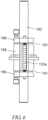
- Figs. 6 and 7 illustrate views of a braking structure according to another embodiment of the present invention.
- a piezoelectric element 133a may expand along the axis of a shaft 193.
- the braking structure shown in Figs. 6 and 7 may include at least one flexure 191 (for example, two flexures 191 in Figs. 6 and 7 ) between portions 196 and 198.
- the portions 196 and 198 are connected via a hinge or equivalent moveable linking means.
- the piezoelectric element 133a expands, the portions 196 of the structure may move relative to 198 via the flexures 191 to twist and bind against the shaft 193 to effect the braking.
Landscapes
- Engineering & Computer Science (AREA)
- General Engineering & Computer Science (AREA)
- Physics & Mathematics (AREA)
- Mechanical Engineering (AREA)
- Chemical & Material Sciences (AREA)
- Analytical Chemistry (AREA)
- General Physics & Mathematics (AREA)
- Optics & Photonics (AREA)
- Machine Tool Units (AREA)
- Braking Arrangements (AREA)
Description
- The present invention generally relates to a braking device, and more particularly, to a piezoelectric braking device.
- In various mechanical systems such as an optical system having a microscope, fixing one component to another component may have to be rigid. However, such a rigid fixing cannot be sufficiently achieved for many reasons. For example, in some applications, position of a component may need to be changed frequently and rapidly. In traditional fixing mechanisms, it is not convenient to repeatedly fixing and releasing a component that requires changing its position frequently and rapidly during operation or setup.
- Therefore, there is a need for mechanical systems so that components can be more rigidly fixed to each other as well as allowing frequent quick fix-release operations.
WO 2009/095950 A1 discloses a clamping device configured to release a clamping force or a braking force acting on a rotating shaft such as a motor output shaft by using a multilayer. piezoelectric element. The multilayer piezoelectric element is assembled to the annular part so that the diameter of the annular part expands and contracts with expansion and contraction of the multilayer piezoelectric element.
The invention is set out in the independent claim 1. Further developments are recited in the dependent claims. - An embodiment of the present invention provides a braking device including:
a piezoelectric element; and a braking portion configured to fix to a member when the piezoelectric element is in a first state, and to release the member when the piezoelectric element is in a second state. The piezoelectric element changes from the first state to the second state when a voltage is applied to the piezoelectric element. - In one embodiment, the braking portion of the braking device is configured to surround the member to clamp the member. A force element may be used to provide the clamping force.
- In one embodiment, the braking portion includes two ends facing to each other, and the braking portion is provided with a gap that is located between the two ends, and a distance between the two ends of the braking portion varies while the piezoelectric element changes from one state to another state. A clearance between the braking portion and the member may be adjustable. When the cross-section of the member is a circle, and the braking device also fixes the member from rotating.
- In one embodiment, the braking device may be used for mounting and releasing of optical element from an optical post. For example, the braking device may be attached to a post holder or an optical mount, so that the position and angle of an optical element may be adjusted when the braking device releases the pole and then locked in place when the braking device fixes post.
- In one embodiment, the braking device may be used in a gimbal having multiple pivots in which the braking device fixes and releases one or more of the multiple pivot pins.
- An embodiment of the present invention provides a positioning system including at least one strut assembly that includes a braking device including a piezoelectric element; and a braking portion configured to fix to a member when the piezoelectric element is in a first state, and to release the member when the piezoelectric element is in a second state.
- Some examples of the above embodiment may include: a hexapod having six strut assemblies with one or more of the braking devices, a tripod having three strut assemblies with one or more of the braking devices, or a monopod having one strut assembly with one braking device.
- An embodiment of the present invention provides a linear drive including a first and second piezoelectric braking devices; a body connecting the two braking devices at two ends along a length of the body; and a processor configured to control the first and second braking devices and to change the length of the body between a first length and a second length, such that when the first braking device fixes to a member, then the second braking device releases the member and the length of the body is at the first length; and when the first braking device releases the member, then the second braking device fixes to the member and the length of the body is at the second length.
-
-
FIG. 1A illustrates a cross-sectional view of a structure according to one embodiment of the present invention. -
FIG. 1B illustrates a side view of a structure according to one embodiment of the present invention. -
FIG. 2A illustrates a cross-sectional view of a structure according to another embodiment of the present invention. -
FIG. 2B illustrates a side view of a structure according to another embodiment of the present invention. -
FIG. 3 is a perspective view of an incident angle tracking microscope mounted on a hexapod according to one embodiment. -
FIG. 4 is a perspective view of a hexapod according to one embodiment. -
FIG. 5 shows a strut assembly according to one embodiment. -
FIGS. 6 and7 illustrate views of a braking structure according to another embodiment of the present invention. - The description of illustrative embodiments according to principles of the present invention is intended to be read in connection with the accompanying drawings, which are to be considered part of the entire written description. In the description of embodiments of the invention disclosed herein, any reference to direction or orientation is merely intended for convenience of description and is not intended in any way to limit the scope of the present invention. Relative terms such as "lower," "upper," "horizontal," "vertical," "above," "below," "up," "down," "top" and "bottom" as well as derivative thereof (e.g., "horizontally," "downwardly," "upwardly," etc.) should be construed to refer to the orientation as then described or as shown in the drawing under discussion. These relative terms are for convenience of description only and do not require that the apparatus be constructed or operated in a particular orientation unless explicitly indicated as such. Terms such as "attached," "affixed," "connected," "coupled," "interconnected," and similar refer to a relationship wherein structures are secured or attached to one another either directly or indirectly through intervening structures, as well as both movable or rigid attachments or relationships, unless expressly described otherwise. Moreover, the features and benefits of the invention are illustrated by reference to the exemplified embodiments. Accordingly, the invention expressly should not be limited to such exemplary embodiments illustrating some possible non-limiting combination of features that may exist alone or in other combinations of features; the scope of the invention being defined by the claims appended hereto.
- This disclosure describes the best mode or modes of practicing the invention as presently contemplated. This description is not intended to be understood in a limiting sense, but provides an example of the invention presented solely for illustrative purposes by reference to the accompanying drawings to advise one of ordinary skill in the art of the advantages and construction of the invention. In the various views of the drawings, like reference characters designate like or similar parts.
- A braking device according to an embodiment is shown in
FIGS. 1A and 1B. FIG. 1A illustrates a cross-sectional view of a structure according to one embodiment of the present invention.FIG. 1B illustrates a side view of a structure according to one embodiment of the present disclosure. - The
structure 100 shown inFigs. 1A and 1B may include amember 110, asupporter 120, and abraking device 130. Themember 110 may include a longitudinal axis Ox. Themember 110 may extends in a longitudinal axis direction Z. Themember 110 may include a circular cross-section. Themember 110 may be made of any kind of material, such as metal, plastic, and composite material. Note that the cross-section of themember 110 is not limited to a circle, any geometrical shape is possible as long as thebraking device 130 is configured to grip one or more surfaces of the bar member. Thesupporter 120 may support thebar member 120 slidably in the longitudinal axis direction Z of themember 110. Thesupporter 120 may surrounds a part of themember 110. In one embodiment, thesupporter 120 may include a hole that may have a circular cross-section that may accommodate a part of themember 110.Supporter 120 may be made of any kind of material, such as metal, plastic, and composite material. - The
braking device 130 may be fixed to thesupporter 120. Thebraking device 130 may be configured to brake themember 110. In one embodiment, thebraking device 130 may be slidable along themember 110. Thebraking device 130 may be made of any kind of material, such as metal, plastic, and composite material. Thebraking device 130 may include abraking portion 131, apiezoelectric element 133, and a forcingelement 135. - The
braking portion 131 may be configured to fix to and be slidable along themember 110. Thebraking portion 131 may be fixed to themember 110 by clamping themember 110. Thebraking portion 131 may surrounds themember 110. In the illustrated example, thebraking portion 131 may include asplit ring 1311 andparts split ring 1311 may surround themember 110 to clamp themember 110. Thesplit ring 1311 of thebraking portion 131 may include twoends braking portion 131 may be provided with agap 131G that is located between twoends part 1313 may be connected to thesplit ring 1311 at a side of theend 131A. Thepart 1315 may be connected to thesplit ring 1311 at a side of theend 131B. Thepart 1315 may be spaced apart from thepart 1313. - The
piezoelectric element 133 may be engaged with thebraking portion 131. In the example shown inFigs. 1A and 1B , thepiezoelectric element 133 may be disposed in thebraking portion 131. Specifically, inFigs. 1A and 1B , thepiezoelectric element 133 may be disposed in a space formed by theparts braking portion 131. Thepiezoelectric element 133 may be disposed along a direction perpendicular to the longitudinal axis direction Z of themember 110. InFigs. 1A and 1B , thepiezoelectric element 133 is disposed along a direction in which the twoends piezoelectric element 133 may include a linear shape. - The
piezoelectric element 133 may be in a first state and a second state. When thepiezoelectric element 133 is in the first state, thebraking portion 131 may be fixed to themember 110. When thepiezoelectric element 133 is in the second state, thebraking portion 131 may not be fixed to themember 110, and may be slidable along themember 110. Themember 110 may be adjusted to thesupporter 120 in the longitudinal direction Z when thebraking portion 131 does not fixed to themember 110. The state of thepiezoelectric element 133 may change from one state to another state when a voltage is applied to the piezoelectric element. For example, thepiezoelectric element 133 may expand in a longitudinal direction of thepiezoelectric element 133 when a voltage is applied to thepiezoelectric element 133. In this example, the first state of thepiezoelectric element 133 may be an expanded state, and the second state of thepiezoelectric element 133 may be a non-expanded state. Alternatively, thepiezoelectric element 133 may contract in the longitudinal direction of thepiezoelectric element 133 when a voltage is applied to thepiezoelectric element 133. In this example, the first state of thepiezoelectric element 133 may be a contracted state, and the second state of thepiezoelectric element 133 may be a non-contracted state. - In the illustrated example shown in
Figs. 1A and 1B , a distance D1 between the twoends braking portion 131 may vary while thepiezoelectric element 133 expands or contracts. - As shown in
Figs. 1A and 1B , thestructure 100 may further include a forcingelement 135. The forcingelement 135 may provide thebraking portion 131 with a force by which thebraking portion 131 clamps themember 110. Examples of the forcingelement 135 include a screw, combination of a bolt and a nut, and a spring. In the example ofFigs. 1A and 1B , the forcingelement 135 may fix one of theparts braking portion 131 to the other one of theparts braking portion 131. - In another embodiment, as shown in
Figs. 2A and 2B , thepiezoelectric element 133 may be disposed along a direction perpendicular to the direction in which the twoends Figs. 2A and 2B , thepiezoelectric element 133 may include a wedge-shaped tip and the wedge-shaped tip of thepiezoelectric element 133 may push the twoends piezoelectric element 133 changes. As such, the distance D1 between the twoends braking portion 131 may vary while thepiezoelectric element 133 expands or contracts. - In the embodiments shown in
Figs. 1A and 1B as well asFigs. 2A and 2B , themember 110 can be rigidly fixed to thesupporter 120 when thebraking portion 131 of thebraking device 130 is fixed to themember 110. This can enhance reliability of fixing of themember 110 to thesupporter 120. In particular, thebraking device 130 may lock rotational and longitudinal movements of themember 110 to thebraking portion 130. In addition, the first and second states of thepiezoelectric element 133 may be switched at a higher speed by switching application of a voltage to thepiezoelectric element 133. Further, thebraking device 130 is configured to adjust a tolerance between the brakingportion 131 and themember 110. - The braking device discussed in view of
Figs. 1A-2B may be applied to various systems. One example of the application of the breaking device includes a adjustable stage for an optical element. In one embodiment, the stage is a hexapod. This allows for a virtual pivot point at which the platform may be rotated about. In other embodiments, the stage may include three strut assemblies arranged as a tripod configuration to provide three degrees of freedom movement of a platform, or include one strut assembly arranged as a monopod configuration to provide one degree of freedom movement of a platform. In these embodiments, one or more of the braking devices are mounted to the strut assembly and configured to brake a shaft from extending, retracting, or rotation -
Fig. 3 illustrates a non-limiting example that a microscope is mounted on an adjustable stage, so that the position and orientation of the entire microscope can be adjusted. -
Fig. 4 is a perspective view of a stage that includes six strut assemblies arranged as a hexapod configuration according to an embodiment. -
FIG. 5 shows a strut assembly according to an embodiment. A shaft in the strut assembly may extend or retract. In one embodiment, the strut assembly includes an actuator to control the extension and retraction of the shaft. In another embodiment, the shaft freely extends and retracts without an actuator. - The
member 110 inFigs. 1A-2B may be theshaft 510 inFig. 5 . Thesupporter 120 inFigs. 1A-2B may be thehousing 520. In addition, thebraking device 130 inFigs. 1A-2B may be located at the end of the housing through which the shaft extends or retracts. In addition, the flexure assembly may be locked when thepiezoelectric element 133 is in the first state, and may be unlocked from theshaft 510 when the piezoelectric element in the second state. In another example, themember 110 inFigs. 1A-2B may be an air cylinder of the strut assembly. In one example, the strut assembly may include twobraking devices 130, and the twobraking devices 130 may alternately perform locking and unlocking functions. - In the embodiments shown in
Fig. 5 , each strut assembly may be locked when thepiezoelectric element 133 is in the first state, and each strut assembly may be unlocked to be adjusted when thepiezoelectric element 133 is in the second state. - In the present embodiments, the
shaft 510 can be rigidly fixed to thehousing 520 for the same reasons discussed above in view ofFigs. 1A-2B . This can enhance reliability of fixing of theshaft 510 to thehousing 520. In addition, as discussed above, the first and second states of the piezoelectric element may be switched at a higher speed by switching application of a voltage to the piezoelectric element. Therefore, the position of theshaft 510 relative to thehousing 520 can be conveniently adjusted. - Furthermore, the braking portion may be precisely honed to the
shaft 510 to create a very tight tolerance between theshaft 510 and the braking portion, so that thepiezoelectric element 133 may need only to expand or contract about 10-20 microns to lock or unlock the brake. - Further, the platform of the apparatus may be a gimbal platform. When the bar member and/or pivot pins of the gimbal apparatus are not clamped by the
braking device 130, the stage of the apparatus ofFigs. 3 may become in a stable posture by gravitation. Then, the bar member and/or the pivot pins may be clamped by thebraking device 130. This means that the stage of the apparatus may move like a gimbal apparatus. In such a case, the stage of the apparatus can be adjusted without an actuator in a strut assembly, and a user may adjust the stage by unlocking the brakes and adjusting the stage to a desired position and then locking the stage in place. - Further, in one embodiment, multiple braking devices may be used together in a system, in which individual braking devices are controlled to fix or release a member according to a programmable sequence. For example, in a system including a first and second braking devices, and a processor is configured to control the first and second braking devices, such that: when the first braking device is in the first state, the second braking device is in the second state; and when the first braking device is in the second state, the second braking device is in the first state. In the application of a linear drive, the first and second braking devices are connected by a bar that can expand and contract. A processor may control the states of the two braking devices and the bar in a sequence such that when the first braking device fixes to a member, then the second braking device releases the member and the length of the body is at the first length; and when the first braking device releases the member, then the second braking device fixes to the member and the length of the body is at the second length. Such sequence of actions would cause the drive to travel along the member.
- It is contemplated that one or more of the braking devices may be used in conjunction with or without other components in a number of systems that may require tight tolerances between moving parts with rapid and controllable braking actions.
-
Figs. 6 and7 illustrate views of a braking structure according to another embodiment of the present invention. InFigs. 6 and7 , apiezoelectric element 133a may expand along the axis of ashaft 193. In one embodiment, the braking structure shown inFigs. 6 and7 may include at least one flexure 191 (for example, twoflexures 191 inFigs. 6 and7 ) betweenportions portions piezoelectric element 133a expands, theportions 196 of the structure may move relative to 198 via theflexures 191 to twist and bind against theshaft 193 to effect the braking. - While the present invention has been described at some length and with some particularity with respect to the several described embodiments, it is not intended that it should be limited to any such particulars or embodiments or any particular embodiment, but it is to be construed with references to the appended claims so as to provide the broadest possible interpretation of such claims in view of the prior art and, therefore, to effectively encompass the intended scope of the invention.
Claims (13)
- A braking device (130) including:a piezoelectric element (133); anda braking portion (131) configured to surround a member (110) and to clamp the member when the piezoelectric element (133) is in a first state, and to release the member (110) when the piezoelectric element (133) is in a second state, wherein the piezoelectric element changes from the first state to the second state when a voltage is applied to the piezoelectric element;and characterized in that the braking portion (131) comprises a split ring (1311) that is split at a location on the ring such that a gap (131G) is formed between a first split end (131A) of the ring and a second split end (131B) of the ring, with the first and second split ends facing each other, andwherein the braking device (130) comprises further a first part (1313) extending from the first split end (131A) away from the member (110) and a second part (1315) extending from the second split end (131B) away from the member (110) and the piezoelectric element (133) is placed between a space formed by the first and second parts (1313, 1315) such that a distance (D1) of the gap (131G) between the facing surfaces of the first and second split ends (131A, 131B) varies while the piezoelectric element (133) changes between the first state and second state.
- The braking device (130) of claim 1, further comprising a forcing element (135) configured to providing a clamping force.
- The braking device (130) of claim 1, wherein the cross-sectional shape of the member is a circle, and the braking device (one) further configured to prevent the member (110) from rotating when the piezoelectric element (133) is in the first state.
- An adjustable optical mount comprising a braking device (130) of claim 1 configured to move along a length of a post or rotate about an axis of the post, such that an adjustment of the location or direction of the optical mount can be made when the braking device (130) releases the post, and then the optical mount can be locked in place when the braking device (130) fixes to the post.
- A gimbal comprising multiple pivots, and one or more of the braking devices (130) of claim 1 configured to fix and release one or more pins of the multiple pivots.
- A positioning system comprising at least one strut assembly comprising the braking device (130) of claim 1.
- The positioning system of claim 6, further comprising a baseplate and a platform,
wherein a first end of each of the at least one strut assembly is connected at a predefined location on top surface of the base plate and a second end of each of the at least one strut assembly is connected at a corresponding predefined location on the bottom surface of the platform. - The positioning system of claim 6, wherein the at least one strut assembly comprises:a linear actuator configured to change a distance between the two ends of the strut assembly along a length of the strut assembly;the at least one strut assembly is locked in position when the piezoelectric element (133) is in the first state, and unlocked from the shaft when the piezoelectric element (133) in the second state.
- The positioning system of claim 7, wherein the at least one strut assembly comprises six strut assemblies arranged as a hexapod configuration to provide six degrees of freedom movement of the platform.
- The positioning system of claim 6, wherein the at least one strut assembly comprises: three strut assemblies arranged as a tripod configuration.
- The positioning system of claim 6, wherein the at least one strut assembly comprises one strut assembly arranged as a monopod configuration.
- The positioning system of claim 7, wherein the at least one strut assembly comprises an air cylinder, and the air cylinder includes the member of the braking device (130).
- A system comprising a first and second braking devices (130) of claim 1, and a processor configured to control the first and second braking devices(130), such that: when the first braking device (130) is in the first state, the second braking device is in the second state; and when the first braking device (130) is in the second state, the second braking device (130) is in the first state, wherein the first and second braking devices (130) are connected by a bar that expands and contracts in synchronous with the state changes of the first and second braking devices(130).
Applications Claiming Priority (2)
| Application Number | Priority Date | Filing Date | Title |
|---|---|---|---|
| US201962800094P | 2019-02-01 | 2019-02-01 | |
| PCT/US2020/015820 WO2020160224A1 (en) | 2019-02-01 | 2020-01-30 | Piezoelectric braking device |
Publications (3)
| Publication Number | Publication Date |
|---|---|
| EP3918209A1 EP3918209A1 (en) | 2021-12-08 |
| EP3918209A4 EP3918209A4 (en) | 2023-03-01 |
| EP3918209B1 true EP3918209B1 (en) | 2024-09-11 |
Family
ID=71837380
Family Applications (1)
| Application Number | Title | Priority Date | Filing Date |
|---|---|---|---|
| EP20748616.8A Active EP3918209B1 (en) | 2019-02-01 | 2020-01-30 | Piezoelectric braking device |
Country Status (5)
| Country | Link |
|---|---|
| US (1) | US11499597B2 (en) |
| EP (1) | EP3918209B1 (en) |
| CN (1) | CN113508235B (en) |
| CA (1) | CA3127904A1 (en) |
| WO (1) | WO2020160224A1 (en) |
Families Citing this family (3)
| Publication number | Priority date | Publication date | Assignee | Title |
|---|---|---|---|---|
| WO2020160224A1 (en) * | 2019-02-01 | 2020-08-06 | Thorlabs, Inc. | Piezoelectric braking device |
| NL2027077B1 (en) * | 2020-12-09 | 2022-07-07 | Eindhoven Medical Robotics B V | Safety brake system for robot arm joints. |
| CN113814432B (en) * | 2021-11-04 | 2022-08-26 | 哈尔滨理工大学 | Rigidity and damping adjustable vibration attenuation boring bar and control method |
Family Cites Families (23)
| Publication number | Priority date | Publication date | Assignee | Title |
|---|---|---|---|---|
| JPS6077685A (en) * | 1983-10-04 | 1985-05-02 | Shoketsu Kinzoku Kogyo Co Ltd | Brake device |
| JPS61167785A (en) * | 1985-01-17 | 1986-07-29 | Nippon Denso Co Ltd | Actuator utilizing piezoelectric element |
| US5365296A (en) * | 1990-10-30 | 1994-11-15 | Canon Kabushiki Kaisha | Motor and an optical apparatus having such motor |
| JPH0658245U (en) * | 1993-01-28 | 1994-08-12 | 株式会社三協精機製作所 | Brake device |
| JPH0942330A (en) * | 1995-07-28 | 1997-02-10 | Sumitomo Constr Mach Co Ltd | Hand drum brake |
| US6022005A (en) * | 1996-09-27 | 2000-02-08 | Trw Inc. | Semi-active vibration isolator and fine positioning mount |
| US6213564B1 (en) * | 1997-04-15 | 2001-04-10 | Face International Corp | Anti-lock brake system with piezoelectric brake actuator |
| DE19855467A1 (en) * | 1998-12-01 | 2000-06-08 | Lucas Ind Plc | Device with a vibration-damped component, in particular a brake |
| SE520097C2 (en) * | 2000-12-05 | 2003-05-27 | Nanofactory Instruments Ab | Micro Positioning Device |
| DE10159239A1 (en) * | 2001-12-03 | 2003-06-26 | Leica Microsystems | Microscope objective, microscope and method for imaging a sample |
| US6749048B2 (en) * | 2002-08-20 | 2004-06-15 | Visteon Global Technologies, Inc. | Fluid seal assembly for a pressured system |
| US20040040797A1 (en) * | 2002-08-30 | 2004-03-04 | Plude Leo W. | Electromechanical aircraft brake system and method incorporating piezoelectric actuator subsystem |
| DE10335795A1 (en) * | 2003-08-05 | 2005-03-10 | Klaus Hofmann | Clamping and / or braking device |
| JP4240384B2 (en) * | 2004-01-26 | 2009-03-18 | 株式会社ハーモニック・ドライブ・システムズ | Brake mechanism |
| JP5064239B2 (en) * | 2005-02-25 | 2012-10-31 | オーチス エレベータ カンパニー | Elevator brake actuator with shape change material for brake adjustment |
| DE102006008403A1 (en) * | 2006-02-21 | 2007-08-30 | Klaus Hofmann | Clamping and/or braking device e.g. pneumatically actuatable clamping and/or braking device, has actuating unit configured as pin or spike and acting upon hydraulic medium through aperture in wall of housing |
| WO2009095950A1 (en) * | 2008-01-29 | 2009-08-06 | Harmonic Drive Systems Inc. | Clamping device |
| JP2009264544A (en) * | 2008-04-28 | 2009-11-12 | Harmonic Drive Syst Ind Co Ltd | Brake device |
| JP2010071436A (en) * | 2008-09-22 | 2010-04-02 | Konica Minolta Opto Inc | Shaft bonding method, and method of manufacturing vibrating type driving device |
| JP6143098B2 (en) * | 2013-08-27 | 2017-06-07 | 国立研究開発法人理化学研究所 | Objective lens drive control method and fluorescence microscope system |
| FI126404B (en) * | 2014-06-06 | 2016-11-15 | Johan Lundin | Optical microscope slide holder |
| US20180155949A1 (en) * | 2015-05-20 | 2018-06-07 | Pouyan ZARNANI | Resilient slip friction joint |
| WO2020160224A1 (en) * | 2019-02-01 | 2020-08-06 | Thorlabs, Inc. | Piezoelectric braking device |
-
2020
- 2020-01-30 WO PCT/US2020/015820 patent/WO2020160224A1/en not_active Ceased
- 2020-01-30 CA CA3127904A patent/CA3127904A1/en active Pending
- 2020-01-30 EP EP20748616.8A patent/EP3918209B1/en active Active
- 2020-01-30 CN CN202080017937.3A patent/CN113508235B/en not_active Expired - Fee Related
- 2020-01-30 US US16/776,888 patent/US11499597B2/en active Active
Also Published As
| Publication number | Publication date |
|---|---|
| EP3918209A1 (en) | 2021-12-08 |
| US20200248766A1 (en) | 2020-08-06 |
| US11499597B2 (en) | 2022-11-15 |
| EP3918209A4 (en) | 2023-03-01 |
| CN113508235B (en) | 2023-08-08 |
| WO2020160224A1 (en) | 2020-08-06 |
| CN113508235A (en) | 2021-10-15 |
| CA3127904A1 (en) | 2020-08-06 |
Similar Documents
| Publication | Publication Date | Title |
|---|---|---|
| US11499597B2 (en) | Piezoelectric braking device | |
| US5986827A (en) | Precision tip-tilt-piston actuator that provides exact constraint | |
| US6402329B1 (en) | Assembly for mounting and correcting the position of an element, such as a mirror, of a space telescope | |
| US4060315A (en) | Precision mirror mount | |
| US6543740B2 (en) | Mechanism for transmitting movement in up to six degrees-of-freedom | |
| GB2227603A (en) | Microdrive apparatus employing piezoelectric/electrostrictive drive | |
| EP3180808B1 (en) | Amplified piezo actuator with coarse adjustment | |
| US20060186285A1 (en) | Multi-axis positioning apparatus | |
| US7579752B2 (en) | Positioning device with a solid-body joint | |
| US7188831B2 (en) | Flexure-type suspension system providing for three degrees of freedom and flexure-type positioning assembly based thereon | |
| CN102822588A (en) | Support heads for optical or photographic camera equipment | |
| JP2020522758A (en) | Adjusting device | |
| JP6938693B2 (en) | Joint | |
| KR102499992B1 (en) | Support apparatus | |
| JP7361874B2 (en) | support unit | |
| EP3341775B1 (en) | Method and apparatus for multiple degree of freedom precision adjustable mount | |
| US7284459B2 (en) | Remote center of rotation positioning device | |
| US9884399B2 (en) | Hinge mechanism for small optics and related methods | |
| WO2006018888A1 (en) | Reflecting mirror supporting mechanism | |
| CN111975811A (en) | Arm fixing device | |
| US10409030B1 (en) | Monolithic flexure mount | |
| EP1810066B1 (en) | A gimbal mount device for supporting a functional element | |
| JP3732101B2 (en) | Tilting device | |
| US9293685B2 (en) | Rotating load bearer | |
| JP2004230521A (en) | Small displacement support device |
Legal Events
| Date | Code | Title | Description |
|---|---|---|---|
| STAA | Information on the status of an ep patent application or granted ep patent |
Free format text: STATUS: THE INTERNATIONAL PUBLICATION HAS BEEN MADE |
|
| PUAI | Public reference made under article 153(3) epc to a published international application that has entered the european phase |
Free format text: ORIGINAL CODE: 0009012 |
|
| STAA | Information on the status of an ep patent application or granted ep patent |
Free format text: STATUS: REQUEST FOR EXAMINATION WAS MADE |
|
| 17P | Request for examination filed |
Effective date: 20210831 |
|
| AK | Designated contracting states |
Kind code of ref document: A1 Designated state(s): AL AT BE BG CH CY CZ DE DK EE ES FI FR GB GR HR HU IE IS IT LI LT LU LV MC MK MT NL NO PL PT RO RS SE SI SK SM TR |
|
| DAV | Request for validation of the european patent (deleted) | ||
| DAX | Request for extension of the european patent (deleted) | ||
| A4 | Supplementary search report drawn up and despatched |
Effective date: 20230127 |
|
| RIC1 | Information provided on ipc code assigned before grant |
Ipc: G02B 21/32 20060101ALI20230123BHEP Ipc: F16B 2/06 20060101AFI20230123BHEP |
|
| GRAP | Despatch of communication of intention to grant a patent |
Free format text: ORIGINAL CODE: EPIDOSNIGR1 |
|
| STAA | Information on the status of an ep patent application or granted ep patent |
Free format text: STATUS: GRANT OF PATENT IS INTENDED |
|
| INTG | Intention to grant announced |
Effective date: 20240404 |
|
| GRAS | Grant fee paid |
Free format text: ORIGINAL CODE: EPIDOSNIGR3 |
|
| GRAA | (expected) grant |
Free format text: ORIGINAL CODE: 0009210 |
|
| STAA | Information on the status of an ep patent application or granted ep patent |
Free format text: STATUS: THE PATENT HAS BEEN GRANTED |
|
| AK | Designated contracting states |
Kind code of ref document: B1 Designated state(s): AL AT BE BG CH CY CZ DE DK EE ES FI FR GB GR HR HU IE IS IT LI LT LU LV MC MK MT NL NO PL PT RO RS SE SI SK SM TR |
|
| REG | Reference to a national code |
Ref country code: GB Ref legal event code: FG4D |
|
| REG | Reference to a national code |
Ref country code: CH Ref legal event code: EP |
|
| REG | Reference to a national code |
Ref country code: DE Ref legal event code: R096 Ref document number: 602020037569 Country of ref document: DE |
|
| REG | Reference to a national code |
Ref country code: IE Ref legal event code: FG4D |
|
| P01 | Opt-out of the competence of the unified patent court (upc) registered |
Free format text: CASE NUMBER: APP_51369/2024 Effective date: 20240911 |
|
| REG | Reference to a national code |
Ref country code: LT Ref legal event code: MG9D |
|
| PG25 | Lapsed in a contracting state [announced via postgrant information from national office to epo] |
Ref country code: NO Free format text: LAPSE BECAUSE OF FAILURE TO SUBMIT A TRANSLATION OF THE DESCRIPTION OR TO PAY THE FEE WITHIN THE PRESCRIBED TIME-LIMIT Effective date: 20241211 |
|
| REG | Reference to a national code |
Ref country code: NL Ref legal event code: MP Effective date: 20240911 |
|
| PG25 | Lapsed in a contracting state [announced via postgrant information from national office to epo] |
Ref country code: GR Free format text: LAPSE BECAUSE OF FAILURE TO SUBMIT A TRANSLATION OF THE DESCRIPTION OR TO PAY THE FEE WITHIN THE PRESCRIBED TIME-LIMIT Effective date: 20241212 Ref country code: FI Free format text: LAPSE BECAUSE OF FAILURE TO SUBMIT A TRANSLATION OF THE DESCRIPTION OR TO PAY THE FEE WITHIN THE PRESCRIBED TIME-LIMIT Effective date: 20240911 |
|
| PG25 | Lapsed in a contracting state [announced via postgrant information from national office to epo] |
Ref country code: BG Free format text: LAPSE BECAUSE OF FAILURE TO SUBMIT A TRANSLATION OF THE DESCRIPTION OR TO PAY THE FEE WITHIN THE PRESCRIBED TIME-LIMIT Effective date: 20240911 |
|
| PG25 | Lapsed in a contracting state [announced via postgrant information from national office to epo] |
Ref country code: LV Free format text: LAPSE BECAUSE OF FAILURE TO SUBMIT A TRANSLATION OF THE DESCRIPTION OR TO PAY THE FEE WITHIN THE PRESCRIBED TIME-LIMIT Effective date: 20240911 |
|
| PG25 | Lapsed in a contracting state [announced via postgrant information from national office to epo] |
Ref country code: HR Free format text: LAPSE BECAUSE OF FAILURE TO SUBMIT A TRANSLATION OF THE DESCRIPTION OR TO PAY THE FEE WITHIN THE PRESCRIBED TIME-LIMIT Effective date: 20240911 |
|
| PG25 | Lapsed in a contracting state [announced via postgrant information from national office to epo] |
Ref country code: ES Free format text: LAPSE BECAUSE OF FAILURE TO SUBMIT A TRANSLATION OF THE DESCRIPTION OR TO PAY THE FEE WITHIN THE PRESCRIBED TIME-LIMIT Effective date: 20240911 Ref country code: RS Free format text: LAPSE BECAUSE OF FAILURE TO SUBMIT A TRANSLATION OF THE DESCRIPTION OR TO PAY THE FEE WITHIN THE PRESCRIBED TIME-LIMIT Effective date: 20241211 |
|
| PG25 | Lapsed in a contracting state [announced via postgrant information from national office to epo] |
Ref country code: RS Free format text: LAPSE BECAUSE OF FAILURE TO SUBMIT A TRANSLATION OF THE DESCRIPTION OR TO PAY THE FEE WITHIN THE PRESCRIBED TIME-LIMIT Effective date: 20241211 Ref country code: NO Free format text: LAPSE BECAUSE OF FAILURE TO SUBMIT A TRANSLATION OF THE DESCRIPTION OR TO PAY THE FEE WITHIN THE PRESCRIBED TIME-LIMIT Effective date: 20241211 Ref country code: LV Free format text: LAPSE BECAUSE OF FAILURE TO SUBMIT A TRANSLATION OF THE DESCRIPTION OR TO PAY THE FEE WITHIN THE PRESCRIBED TIME-LIMIT Effective date: 20240911 Ref country code: HR Free format text: LAPSE BECAUSE OF FAILURE TO SUBMIT A TRANSLATION OF THE DESCRIPTION OR TO PAY THE FEE WITHIN THE PRESCRIBED TIME-LIMIT Effective date: 20240911 Ref country code: GR Free format text: LAPSE BECAUSE OF FAILURE TO SUBMIT A TRANSLATION OF THE DESCRIPTION OR TO PAY THE FEE WITHIN THE PRESCRIBED TIME-LIMIT Effective date: 20241212 Ref country code: FI Free format text: LAPSE BECAUSE OF FAILURE TO SUBMIT A TRANSLATION OF THE DESCRIPTION OR TO PAY THE FEE WITHIN THE PRESCRIBED TIME-LIMIT Effective date: 20240911 Ref country code: ES Free format text: LAPSE BECAUSE OF FAILURE TO SUBMIT A TRANSLATION OF THE DESCRIPTION OR TO PAY THE FEE WITHIN THE PRESCRIBED TIME-LIMIT Effective date: 20240911 Ref country code: BG Free format text: LAPSE BECAUSE OF FAILURE TO SUBMIT A TRANSLATION OF THE DESCRIPTION OR TO PAY THE FEE WITHIN THE PRESCRIBED TIME-LIMIT Effective date: 20240911 |
|
| REG | Reference to a national code |
Ref country code: AT Ref legal event code: MK05 Ref document number: 1722916 Country of ref document: AT Kind code of ref document: T Effective date: 20240911 |
|
| PG25 | Lapsed in a contracting state [announced via postgrant information from national office to epo] |
Ref country code: NL Free format text: LAPSE BECAUSE OF FAILURE TO SUBMIT A TRANSLATION OF THE DESCRIPTION OR TO PAY THE FEE WITHIN THE PRESCRIBED TIME-LIMIT Effective date: 20240911 |
|
| PG25 | Lapsed in a contracting state [announced via postgrant information from national office to epo] |
Ref country code: PT Free format text: LAPSE BECAUSE OF FAILURE TO SUBMIT A TRANSLATION OF THE DESCRIPTION OR TO PAY THE FEE WITHIN THE PRESCRIBED TIME-LIMIT Effective date: 20250113 Ref country code: IS Free format text: LAPSE BECAUSE OF FAILURE TO SUBMIT A TRANSLATION OF THE DESCRIPTION OR TO PAY THE FEE WITHIN THE PRESCRIBED TIME-LIMIT Effective date: 20250111 |
|
| PG25 | Lapsed in a contracting state [announced via postgrant information from national office to epo] |
Ref country code: RO Free format text: LAPSE BECAUSE OF FAILURE TO SUBMIT A TRANSLATION OF THE DESCRIPTION OR TO PAY THE FEE WITHIN THE PRESCRIBED TIME-LIMIT Effective date: 20240911 Ref country code: SM Free format text: LAPSE BECAUSE OF FAILURE TO SUBMIT A TRANSLATION OF THE DESCRIPTION OR TO PAY THE FEE WITHIN THE PRESCRIBED TIME-LIMIT Effective date: 20240911 |
|
| PG25 | Lapsed in a contracting state [announced via postgrant information from national office to epo] |
Ref country code: EE Free format text: LAPSE BECAUSE OF FAILURE TO SUBMIT A TRANSLATION OF THE DESCRIPTION OR TO PAY THE FEE WITHIN THE PRESCRIBED TIME-LIMIT Effective date: 20240911 Ref country code: AT Free format text: LAPSE BECAUSE OF FAILURE TO SUBMIT A TRANSLATION OF THE DESCRIPTION OR TO PAY THE FEE WITHIN THE PRESCRIBED TIME-LIMIT Effective date: 20240911 |
|
| PG25 | Lapsed in a contracting state [announced via postgrant information from national office to epo] |
Ref country code: CZ Free format text: LAPSE BECAUSE OF FAILURE TO SUBMIT A TRANSLATION OF THE DESCRIPTION OR TO PAY THE FEE WITHIN THE PRESCRIBED TIME-LIMIT Effective date: 20240911 Ref country code: PL Free format text: LAPSE BECAUSE OF FAILURE TO SUBMIT A TRANSLATION OF THE DESCRIPTION OR TO PAY THE FEE WITHIN THE PRESCRIBED TIME-LIMIT Effective date: 20240911 |
|
| PG25 | Lapsed in a contracting state [announced via postgrant information from national office to epo] |
Ref country code: SK Free format text: LAPSE BECAUSE OF FAILURE TO SUBMIT A TRANSLATION OF THE DESCRIPTION OR TO PAY THE FEE WITHIN THE PRESCRIBED TIME-LIMIT Effective date: 20240911 Ref country code: IT Free format text: LAPSE BECAUSE OF FAILURE TO SUBMIT A TRANSLATION OF THE DESCRIPTION OR TO PAY THE FEE WITHIN THE PRESCRIBED TIME-LIMIT Effective date: 20240911 |
|
| REG | Reference to a national code |
Ref country code: DE Ref legal event code: R097 Ref document number: 602020037569 Country of ref document: DE |
|
| PG25 | Lapsed in a contracting state [announced via postgrant information from national office to epo] |
Ref country code: DK Free format text: LAPSE BECAUSE OF FAILURE TO SUBMIT A TRANSLATION OF THE DESCRIPTION OR TO PAY THE FEE WITHIN THE PRESCRIBED TIME-LIMIT Effective date: 20240911 |
|
| PLBE | No opposition filed within time limit |
Free format text: ORIGINAL CODE: 0009261 |
|
| STAA | Information on the status of an ep patent application or granted ep patent |
Free format text: STATUS: NO OPPOSITION FILED WITHIN TIME LIMIT |
|
| REG | Reference to a national code |
Ref country code: DE Ref legal event code: R119 Ref document number: 602020037569 Country of ref document: DE |
|
| 26N | No opposition filed |
Effective date: 20250612 |
|
| REG | Reference to a national code |
Ref country code: CH Ref legal event code: PL |
|
| PG25 | Lapsed in a contracting state [announced via postgrant information from national office to epo] |
Ref country code: SE Free format text: LAPSE BECAUSE OF FAILURE TO SUBMIT A TRANSLATION OF THE DESCRIPTION OR TO PAY THE FEE WITHIN THE PRESCRIBED TIME-LIMIT Effective date: 20240911 |
|
| PG25 | Lapsed in a contracting state [announced via postgrant information from national office to epo] |
Ref country code: LU Free format text: LAPSE BECAUSE OF NON-PAYMENT OF DUE FEES Effective date: 20250130 Ref country code: MC Free format text: LAPSE BECAUSE OF FAILURE TO SUBMIT A TRANSLATION OF THE DESCRIPTION OR TO PAY THE FEE WITHIN THE PRESCRIBED TIME-LIMIT Effective date: 20240911 |
|
| GBPC | Gb: european patent ceased through non-payment of renewal fee |
Effective date: 20250130 |
|
| PG25 | Lapsed in a contracting state [announced via postgrant information from national office to epo] |
Ref country code: DE Free format text: LAPSE BECAUSE OF NON-PAYMENT OF DUE FEES Effective date: 20250801 |
|
| PG25 | Lapsed in a contracting state [announced via postgrant information from national office to epo] |
Ref country code: GB Free format text: LAPSE BECAUSE OF NON-PAYMENT OF DUE FEES Effective date: 20250130 Ref country code: BE Free format text: LAPSE BECAUSE OF NON-PAYMENT OF DUE FEES Effective date: 20250131 |
|
| PG25 | Lapsed in a contracting state [announced via postgrant information from national office to epo] |
Ref country code: FR Free format text: LAPSE BECAUSE OF NON-PAYMENT OF DUE FEES Effective date: 20250131 |
|
| PG25 | Lapsed in a contracting state [announced via postgrant information from national office to epo] |
Ref country code: CH Free format text: LAPSE BECAUSE OF NON-PAYMENT OF DUE FEES Effective date: 20250131 |
|
| REG | Reference to a national code |
Ref country code: BE Ref legal event code: MM Effective date: 20250131 |
|
| PG25 | Lapsed in a contracting state [announced via postgrant information from national office to epo] |
Ref country code: IE Free format text: LAPSE BECAUSE OF NON-PAYMENT OF DUE FEES Effective date: 20250130 |