EP3917829B1 - Flying vehicle systems and methods - Google Patents
Flying vehicle systems and methods Download PDFInfo
- Publication number
- EP3917829B1 EP3917829B1 EP21732799.8A EP21732799A EP3917829B1 EP 3917829 B1 EP3917829 B1 EP 3917829B1 EP 21732799 A EP21732799 A EP 21732799A EP 3917829 B1 EP3917829 B1 EP 3917829B1
- Authority
- EP
- European Patent Office
- Prior art keywords
- uav
- load
- end portion
- battery
- control system
- Prior art date
- Legal status (The legal status is an assumption and is not a legal conclusion. Google has not performed a legal analysis and makes no representation as to the accuracy of the status listed.)
- Active
Links
Images


Classifications
-
- B—PERFORMING OPERATIONS; TRANSPORTING
- B64—AIRCRAFT; AVIATION; COSMONAUTICS
- B64U—UNMANNED AERIAL VEHICLES [UAV]; EQUIPMENT THEREFOR
- B64U10/00—Type of UAV
- B64U10/10—Rotorcrafts
- B64U10/13—Flying platforms
-
- B—PERFORMING OPERATIONS; TRANSPORTING
- B60—VEHICLES IN GENERAL
- B60L—PROPULSION OF ELECTRICALLY-PROPELLED VEHICLES; SUPPLYING ELECTRIC POWER FOR AUXILIARY EQUIPMENT OF ELECTRICALLY-PROPELLED VEHICLES; ELECTRODYNAMIC BRAKE SYSTEMS FOR VEHICLES IN GENERAL; MAGNETIC SUSPENSION OR LEVITATION FOR VEHICLES; MONITORING OPERATING VARIABLES OF ELECTRICALLY-PROPELLED VEHICLES; ELECTRIC SAFETY DEVICES FOR ELECTRICALLY-PROPELLED VEHICLES
- B60L5/00—Current collectors for power supply lines of electrically-propelled vehicles
- B60L5/36—Current collectors for power supply lines of electrically-propelled vehicles with means for collecting current simultaneously from more than one conductor, e.g. from more than one phase
-
- B—PERFORMING OPERATIONS; TRANSPORTING
- B60—VEHICLES IN GENERAL
- B60L—PROPULSION OF ELECTRICALLY-PROPELLED VEHICLES; SUPPLYING ELECTRIC POWER FOR AUXILIARY EQUIPMENT OF ELECTRICALLY-PROPELLED VEHICLES; ELECTRODYNAMIC BRAKE SYSTEMS FOR VEHICLES IN GENERAL; MAGNETIC SUSPENSION OR LEVITATION FOR VEHICLES; MONITORING OPERATING VARIABLES OF ELECTRICALLY-PROPELLED VEHICLES; ELECTRIC SAFETY DEVICES FOR ELECTRICALLY-PROPELLED VEHICLES
- B60L50/00—Electric propulsion with power supplied within the vehicle
- B60L50/50—Electric propulsion with power supplied within the vehicle using propulsion power supplied by batteries or fuel cells
- B60L50/60—Electric propulsion with power supplied within the vehicle using propulsion power supplied by batteries or fuel cells using power supplied by batteries
- B60L50/66—Arrangements of batteries
-
- B—PERFORMING OPERATIONS; TRANSPORTING
- B60—VEHICLES IN GENERAL
- B60L—PROPULSION OF ELECTRICALLY-PROPELLED VEHICLES; SUPPLYING ELECTRIC POWER FOR AUXILIARY EQUIPMENT OF ELECTRICALLY-PROPELLED VEHICLES; ELECTRODYNAMIC BRAKE SYSTEMS FOR VEHICLES IN GENERAL; MAGNETIC SUSPENSION OR LEVITATION FOR VEHICLES; MONITORING OPERATING VARIABLES OF ELECTRICALLY-PROPELLED VEHICLES; ELECTRIC SAFETY DEVICES FOR ELECTRICALLY-PROPELLED VEHICLES
- B60L53/00—Methods of charging batteries, specially adapted for electric vehicles; Charging stations or on-board charging equipment therefor; Exchange of energy storage elements in electric vehicles
- B60L53/10—Methods of charging batteries, specially adapted for electric vehicles; Charging stations or on-board charging equipment therefor; Exchange of energy storage elements in electric vehicles characterised by the energy transfer between the charging station and the vehicle
- B60L53/14—Conductive energy transfer
- B60L53/16—Connectors, e.g. plugs or sockets, specially adapted for charging electric vehicles
-
- B—PERFORMING OPERATIONS; TRANSPORTING
- B60—VEHICLES IN GENERAL
- B60L—PROPULSION OF ELECTRICALLY-PROPELLED VEHICLES; SUPPLYING ELECTRIC POWER FOR AUXILIARY EQUIPMENT OF ELECTRICALLY-PROPELLED VEHICLES; ELECTRODYNAMIC BRAKE SYSTEMS FOR VEHICLES IN GENERAL; MAGNETIC SUSPENSION OR LEVITATION FOR VEHICLES; MONITORING OPERATING VARIABLES OF ELECTRICALLY-PROPELLED VEHICLES; ELECTRIC SAFETY DEVICES FOR ELECTRICALLY-PROPELLED VEHICLES
- B60L53/00—Methods of charging batteries, specially adapted for electric vehicles; Charging stations or on-board charging equipment therefor; Exchange of energy storage elements in electric vehicles
- B60L53/30—Constructional details of charging stations
- B60L53/35—Means for automatic or assisted adjustment of the relative position of charging devices and vehicles
- B60L53/36—Means for automatic or assisted adjustment of the relative position of charging devices and vehicles by positioning the vehicle
-
- B—PERFORMING OPERATIONS; TRANSPORTING
- B60—VEHICLES IN GENERAL
- B60L—PROPULSION OF ELECTRICALLY-PROPELLED VEHICLES; SUPPLYING ELECTRIC POWER FOR AUXILIARY EQUIPMENT OF ELECTRICALLY-PROPELLED VEHICLES; ELECTRODYNAMIC BRAKE SYSTEMS FOR VEHICLES IN GENERAL; MAGNETIC SUSPENSION OR LEVITATION FOR VEHICLES; MONITORING OPERATING VARIABLES OF ELECTRICALLY-PROPELLED VEHICLES; ELECTRIC SAFETY DEVICES FOR ELECTRICALLY-PROPELLED VEHICLES
- B60L53/00—Methods of charging batteries, specially adapted for electric vehicles; Charging stations or on-board charging equipment therefor; Exchange of energy storage elements in electric vehicles
- B60L53/80—Exchanging energy storage elements, e.g. removable batteries
-
- B—PERFORMING OPERATIONS; TRANSPORTING
- B64—AIRCRAFT; AVIATION; COSMONAUTICS
- B64C—AEROPLANES; HELICOPTERS
- B64C25/00—Alighting gear
- B64C25/001—Devices not provided for in the groups B64C25/02 - B64C25/68
-
- B—PERFORMING OPERATIONS; TRANSPORTING
- B64—AIRCRAFT; AVIATION; COSMONAUTICS
- B64D—EQUIPMENT FOR FITTING IN OR TO AIRCRAFT; FLIGHT SUITS; PARACHUTES; ARRANGEMENT OR MOUNTING OF POWER PLANTS OR PROPULSION TRANSMISSIONS IN AIRCRAFT
- B64D1/00—Dropping, ejecting, releasing or receiving articles, liquids, or the like, in flight
- B64D1/02—Dropping, ejecting, or releasing articles
- B64D1/08—Dropping, ejecting, or releasing articles the articles being load-carrying devices
- B64D1/10—Stowage arrangements for the devices in aircraft
-
- B—PERFORMING OPERATIONS; TRANSPORTING
- B64—AIRCRAFT; AVIATION; COSMONAUTICS
- B64D—EQUIPMENT FOR FITTING IN OR TO AIRCRAFT; FLIGHT SUITS; PARACHUTES; ARRANGEMENT OR MOUNTING OF POWER PLANTS OR PROPULSION TRANSMISSIONS IN AIRCRAFT
- B64D1/00—Dropping, ejecting, releasing or receiving articles, liquids, or the like, in flight
- B64D1/02—Dropping, ejecting, or releasing articles
- B64D1/08—Dropping, ejecting, or releasing articles the articles being load-carrying devices
- B64D1/12—Releasing
-
- B—PERFORMING OPERATIONS; TRANSPORTING
- B64—AIRCRAFT; AVIATION; COSMONAUTICS
- B64D—EQUIPMENT FOR FITTING IN OR TO AIRCRAFT; FLIGHT SUITS; PARACHUTES; ARRANGEMENT OR MOUNTING OF POWER PLANTS OR PROPULSION TRANSMISSIONS IN AIRCRAFT
- B64D1/00—Dropping, ejecting, releasing or receiving articles, liquids, or the like, in flight
- B64D1/22—Taking-up articles from earth's surface
-
- B—PERFORMING OPERATIONS; TRANSPORTING
- B64—AIRCRAFT; AVIATION; COSMONAUTICS
- B64D—EQUIPMENT FOR FITTING IN OR TO AIRCRAFT; FLIGHT SUITS; PARACHUTES; ARRANGEMENT OR MOUNTING OF POWER PLANTS OR PROPULSION TRANSMISSIONS IN AIRCRAFT
- B64D41/00—Power installations for auxiliary purposes
-
- B—PERFORMING OPERATIONS; TRANSPORTING
- B64—AIRCRAFT; AVIATION; COSMONAUTICS
- B64F—GROUND OR AIRCRAFT-CARRIER-DECK INSTALLATIONS SPECIALLY ADAPTED FOR USE IN CONNECTION WITH AIRCRAFT; DESIGNING, MANUFACTURING, ASSEMBLING, CLEANING, MAINTAINING OR REPAIRING AIRCRAFT, NOT OTHERWISE PROVIDED FOR; HANDLING, TRANSPORTING, TESTING OR INSPECTING AIRCRAFT COMPONENTS, NOT OTHERWISE PROVIDED FOR
- B64F1/00—Ground or aircraft-carrier-deck installations
- B64F1/32—Ground or aircraft-carrier-deck installations for handling freight
-
- B—PERFORMING OPERATIONS; TRANSPORTING
- B64—AIRCRAFT; AVIATION; COSMONAUTICS
- B64U—UNMANNED AERIAL VEHICLES [UAV]; EQUIPMENT THEREFOR
- B64U30/00—Means for producing lift; Empennages; Arrangements thereof
- B64U30/20—Rotors; Rotor supports
-
- B—PERFORMING OPERATIONS; TRANSPORTING
- B64—AIRCRAFT; AVIATION; COSMONAUTICS
- B64U—UNMANNED AERIAL VEHICLES [UAV]; EQUIPMENT THEREFOR
- B64U50/00—Propulsion; Power supply
- B64U50/10—Propulsion
- B64U50/19—Propulsion using electrically powered motors
-
- B—PERFORMING OPERATIONS; TRANSPORTING
- B64—AIRCRAFT; AVIATION; COSMONAUTICS
- B64U—UNMANNED AERIAL VEHICLES [UAV]; EQUIPMENT THEREFOR
- B64U70/00—Launching, take-off or landing arrangements
- B64U70/30—Launching, take-off or landing arrangements for capturing UAVs in flight by ground or sea-based arresting gear, e.g. by a cable or a net
-
- B—PERFORMING OPERATIONS; TRANSPORTING
- B66—HOISTING; LIFTING; HAULING
- B66C—CRANES; LOAD-ENGAGING ELEMENTS OR DEVICES FOR CRANES, CAPSTANS, WINCHES, OR TACKLES
- B66C1/00—Load-engaging elements or devices attached to lifting or lowering gear of cranes or adapted for connection therewith for transmitting lifting forces to articles or groups of articles
- B66C1/10—Load-engaging elements or devices attached to lifting or lowering gear of cranes or adapted for connection therewith for transmitting lifting forces to articles or groups of articles by mechanical means
- B66C1/22—Rigid members, e.g. L-shaped members, with parts engaging the under surface of the loads; Crane hooks
- B66C1/34—Crane hooks
- B66C1/36—Crane hooks with means, e.g. spring-biased detents, for preventing inadvertent disengagement of loads
-
- B—PERFORMING OPERATIONS; TRANSPORTING
- B66—HOISTING; LIFTING; HAULING
- B66D—CAPSTANS; WINCHES; TACKLES, e.g. PULLEY BLOCKS; HOISTS
- B66D1/00—Rope, cable, or chain winding mechanisms; Capstans
- B66D1/28—Other constructional details
- B66D1/40—Control devices
- B66D1/48—Control devices automatic
-
- B—PERFORMING OPERATIONS; TRANSPORTING
- B66—HOISTING; LIFTING; HAULING
- B66F—HOISTING, LIFTING, HAULING OR PUSHING, NOT OTHERWISE PROVIDED FOR, e.g. DEVICES WHICH APPLY A LIFTING OR PUSHING FORCE DIRECTLY TO THE SURFACE OF A LOAD
- B66F19/00—Hoisting, lifting, hauling or pushing, not otherwise provided for
-
- G—PHYSICS
- G05—CONTROLLING; REGULATING
- G05D—SYSTEMS FOR CONTROLLING OR REGULATING NON-ELECTRIC VARIABLES
- G05D1/00—Control of position, course, altitude or attitude of land, water, air or space vehicles, e.g. using automatic pilots
- G05D1/0094—Control of position, course, altitude or attitude of land, water, air or space vehicles, e.g. using automatic pilots involving pointing a payload, e.g. camera, weapon, sensor, towards a fixed or moving target
-
- G—PHYSICS
- G05—CONTROLLING; REGULATING
- G05D—SYSTEMS FOR CONTROLLING OR REGULATING NON-ELECTRIC VARIABLES
- G05D1/00—Control of position, course, altitude or attitude of land, water, air or space vehicles, e.g. using automatic pilots
- G05D1/10—Simultaneous control of position or course in three dimensions
- G05D1/101—Simultaneous control of position or course in three dimensions specially adapted for aircraft
- G05D1/106—Change initiated in response to external conditions, e.g. avoidance of elevated terrain or of no-fly zones
-
- G—PHYSICS
- G08—SIGNALLING
- G08G—TRAFFIC CONTROL SYSTEMS
- G08G5/00—Traffic control systems for aircraft
- G08G5/50—Navigation or guidance aids
- G08G5/55—Navigation or guidance aids for a single aircraft
-
- G—PHYSICS
- G08—SIGNALLING
- G08G—TRAFFIC CONTROL SYSTEMS
- G08G5/00—Traffic control systems for aircraft
- G08G5/50—Navigation or guidance aids
- G08G5/57—Navigation or guidance aids for unmanned aircraft
-
- B—PERFORMING OPERATIONS; TRANSPORTING
- B60—VEHICLES IN GENERAL
- B60L—PROPULSION OF ELECTRICALLY-PROPELLED VEHICLES; SUPPLYING ELECTRIC POWER FOR AUXILIARY EQUIPMENT OF ELECTRICALLY-PROPELLED VEHICLES; ELECTRODYNAMIC BRAKE SYSTEMS FOR VEHICLES IN GENERAL; MAGNETIC SUSPENSION OR LEVITATION FOR VEHICLES; MONITORING OPERATING VARIABLES OF ELECTRICALLY-PROPELLED VEHICLES; ELECTRIC SAFETY DEVICES FOR ELECTRICALLY-PROPELLED VEHICLES
- B60L2200/00—Type of vehicles
- B60L2200/10—Air crafts
-
- B—PERFORMING OPERATIONS; TRANSPORTING
- B60—VEHICLES IN GENERAL
- B60L—PROPULSION OF ELECTRICALLY-PROPELLED VEHICLES; SUPPLYING ELECTRIC POWER FOR AUXILIARY EQUIPMENT OF ELECTRICALLY-PROPELLED VEHICLES; ELECTRODYNAMIC BRAKE SYSTEMS FOR VEHICLES IN GENERAL; MAGNETIC SUSPENSION OR LEVITATION FOR VEHICLES; MONITORING OPERATING VARIABLES OF ELECTRICALLY-PROPELLED VEHICLES; ELECTRIC SAFETY DEVICES FOR ELECTRICALLY-PROPELLED VEHICLES
- B60L2240/00—Control parameters of input or output; Target parameters
- B60L2240/60—Navigation input
- B60L2240/62—Vehicle position
-
- B—PERFORMING OPERATIONS; TRANSPORTING
- B64—AIRCRAFT; AVIATION; COSMONAUTICS
- B64D—EQUIPMENT FOR FITTING IN OR TO AIRCRAFT; FLIGHT SUITS; PARACHUTES; ARRANGEMENT OR MOUNTING OF POWER PLANTS OR PROPULSION TRANSMISSIONS IN AIRCRAFT
- B64D45/00—Aircraft indicators or protectors not otherwise provided for
- B64D2045/0085—Devices for aircraft health monitoring, e.g. monitoring flutter or vibration
-
- B—PERFORMING OPERATIONS; TRANSPORTING
- B64—AIRCRAFT; AVIATION; COSMONAUTICS
- B64U—UNMANNED AERIAL VEHICLES [UAV]; EQUIPMENT THEREFOR
- B64U2101/00—UAVs specially adapted for particular uses or applications
- B64U2101/60—UAVs specially adapted for particular uses or applications for transporting passengers; for transporting goods other than weapons
-
- B—PERFORMING OPERATIONS; TRANSPORTING
- B64—AIRCRAFT; AVIATION; COSMONAUTICS
- B64U—UNMANNED AERIAL VEHICLES [UAV]; EQUIPMENT THEREFOR
- B64U2201/00—UAVs characterised by their flight controls
- B64U2201/10—UAVs characterised by their flight controls autonomous, i.e. by navigating independently from ground or air stations, e.g. by using inertial navigation systems [INS]
-
- B—PERFORMING OPERATIONS; TRANSPORTING
- B64—AIRCRAFT; AVIATION; COSMONAUTICS
- B64U—UNMANNED AERIAL VEHICLES [UAV]; EQUIPMENT THEREFOR
- B64U70/00—Launching, take-off or landing arrangements
- B64U70/90—Launching from or landing on platforms
- B64U70/92—Portable platforms
-
- B—PERFORMING OPERATIONS; TRANSPORTING
- B64—AIRCRAFT; AVIATION; COSMONAUTICS
- B64U—UNMANNED AERIAL VEHICLES [UAV]; EQUIPMENT THEREFOR
- B64U80/00—Transport or storage specially adapted for UAVs
- B64U80/70—Transport or storage specially adapted for UAVs in containers
-
- B—PERFORMING OPERATIONS; TRANSPORTING
- B64—AIRCRAFT; AVIATION; COSMONAUTICS
- B64U—UNMANNED AERIAL VEHICLES [UAV]; EQUIPMENT THEREFOR
- B64U80/00—Transport or storage specially adapted for UAVs
- B64U80/80—Transport or storage specially adapted for UAVs by vehicles
- B64U80/86—Land vehicles
-
- Y—GENERAL TAGGING OF NEW TECHNOLOGICAL DEVELOPMENTS; GENERAL TAGGING OF CROSS-SECTIONAL TECHNOLOGIES SPANNING OVER SEVERAL SECTIONS OF THE IPC; TECHNICAL SUBJECTS COVERED BY FORMER USPC CROSS-REFERENCE ART COLLECTIONS [XRACs] AND DIGESTS
- Y02—TECHNOLOGIES OR APPLICATIONS FOR MITIGATION OR ADAPTATION AGAINST CLIMATE CHANGE
- Y02T—CLIMATE CHANGE MITIGATION TECHNOLOGIES RELATED TO TRANSPORTATION
- Y02T10/00—Road transport of goods or passengers
- Y02T10/60—Other road transportation technologies with climate change mitigation effect
- Y02T10/70—Energy storage systems for electromobility, e.g. batteries
-
- Y—GENERAL TAGGING OF NEW TECHNOLOGICAL DEVELOPMENTS; GENERAL TAGGING OF CROSS-SECTIONAL TECHNOLOGIES SPANNING OVER SEVERAL SECTIONS OF THE IPC; TECHNICAL SUBJECTS COVERED BY FORMER USPC CROSS-REFERENCE ART COLLECTIONS [XRACs] AND DIGESTS
- Y02—TECHNOLOGIES OR APPLICATIONS FOR MITIGATION OR ADAPTATION AGAINST CLIMATE CHANGE
- Y02T—CLIMATE CHANGE MITIGATION TECHNOLOGIES RELATED TO TRANSPORTATION
- Y02T10/00—Road transport of goods or passengers
- Y02T10/60—Other road transportation technologies with climate change mitigation effect
- Y02T10/7072—Electromobility specific charging systems or methods for batteries, ultracapacitors, supercapacitors or double-layer capacitors
-
- Y—GENERAL TAGGING OF NEW TECHNOLOGICAL DEVELOPMENTS; GENERAL TAGGING OF CROSS-SECTIONAL TECHNOLOGIES SPANNING OVER SEVERAL SECTIONS OF THE IPC; TECHNICAL SUBJECTS COVERED BY FORMER USPC CROSS-REFERENCE ART COLLECTIONS [XRACs] AND DIGESTS
- Y02—TECHNOLOGIES OR APPLICATIONS FOR MITIGATION OR ADAPTATION AGAINST CLIMATE CHANGE
- Y02T—CLIMATE CHANGE MITIGATION TECHNOLOGIES RELATED TO TRANSPORTATION
- Y02T10/00—Road transport of goods or passengers
- Y02T10/60—Other road transportation technologies with climate change mitigation effect
- Y02T10/72—Electric energy management in electromobility
-
- Y—GENERAL TAGGING OF NEW TECHNOLOGICAL DEVELOPMENTS; GENERAL TAGGING OF CROSS-SECTIONAL TECHNOLOGIES SPANNING OVER SEVERAL SECTIONS OF THE IPC; TECHNICAL SUBJECTS COVERED BY FORMER USPC CROSS-REFERENCE ART COLLECTIONS [XRACs] AND DIGESTS
- Y02—TECHNOLOGIES OR APPLICATIONS FOR MITIGATION OR ADAPTATION AGAINST CLIMATE CHANGE
- Y02T—CLIMATE CHANGE MITIGATION TECHNOLOGIES RELATED TO TRANSPORTATION
- Y02T90/00—Enabling technologies or technologies with a potential or indirect contribution to GHG emissions mitigation
- Y02T90/10—Technologies relating to charging of electric vehicles
- Y02T90/12—Electric charging stations
-
- Y—GENERAL TAGGING OF NEW TECHNOLOGICAL DEVELOPMENTS; GENERAL TAGGING OF CROSS-SECTIONAL TECHNOLOGIES SPANNING OVER SEVERAL SECTIONS OF THE IPC; TECHNICAL SUBJECTS COVERED BY FORMER USPC CROSS-REFERENCE ART COLLECTIONS [XRACs] AND DIGESTS
- Y02—TECHNOLOGIES OR APPLICATIONS FOR MITIGATION OR ADAPTATION AGAINST CLIMATE CHANGE
- Y02T—CLIMATE CHANGE MITIGATION TECHNOLOGIES RELATED TO TRANSPORTATION
- Y02T90/00—Enabling technologies or technologies with a potential or indirect contribution to GHG emissions mitigation
- Y02T90/10—Technologies relating to charging of electric vehicles
- Y02T90/14—Plug-in electric vehicles
-
- Y—GENERAL TAGGING OF NEW TECHNOLOGICAL DEVELOPMENTS; GENERAL TAGGING OF CROSS-SECTIONAL TECHNOLOGIES SPANNING OVER SEVERAL SECTIONS OF THE IPC; TECHNICAL SUBJECTS COVERED BY FORMER USPC CROSS-REFERENCE ART COLLECTIONS [XRACs] AND DIGESTS
- Y02—TECHNOLOGIES OR APPLICATIONS FOR MITIGATION OR ADAPTATION AGAINST CLIMATE CHANGE
- Y02T—CLIMATE CHANGE MITIGATION TECHNOLOGIES RELATED TO TRANSPORTATION
- Y02T90/00—Enabling technologies or technologies with a potential or indirect contribution to GHG emissions mitigation
- Y02T90/10—Technologies relating to charging of electric vehicles
- Y02T90/16—Information or communication technologies improving the operation of electric vehicles
Definitions
- the present disclosure generally relates to flying vehicles, and more particularly but not exclusively relates to systems and methods relating to unmanned aerial vehicles (UAVs) and unmanned aerial systems (UASs).
- UAVs unmanned aerial vehicles
- UASs unmanned aerial systems
- UAVs unmanned aerial vehicles
- many existing UAV devices and systems suffer from certain drawbacks and limitations.
- certain existing delivery drones include a winch operable to lower the package via a line attached to the winch
- many such delivery UAVs lower the package at a constant velocity. Should the velocity be too high, the package may become damaged by impact with the ground. Should the velocity be too low, the delivery time will be unnecessarily extended.
- the line become caught or tangled, the UAV may be prevented from completing its mission and/or returning to its point of origin.
- UAV operating methods involve landing the UAV on a flat landing pad.
- these operating methods typically require that the UAV be controlled with relatively low tolerances, particularly in instances in which the landing pad is relatively small and/or is mounted to a moving vehicle.
- more complex control algorithms may be required to ensure that the UAV lands within a relatively small zone, which may present a moving target.
- certain UAVs require that the battery be removed for charging, or that a charge cord be attached to the UAV for charging the battery.
- the UAV loses power while the battery is removed, and must reboot when a new battery is installed.
- the operator In situations that require a charge cord be attached, the operator must perform the extra step of attaching the cord in order for the battery to begin charging. In either event, the operator must take some positive action to begin the charging process, which can be time-consuming and/or laborious, and which may result in material wear and cause material failure.
- the process of rebooting can be time-consuming.
- WO 2018/071592 A1 discloses an apparatus and method for balancing aircraft with robotic arms.
- a hover-capable flying machine such as a drone that includes a robotic arm extending from the body, and an instrumentality for balancing the machine in response to disturbances such as those caused by picking up and dropping of the payload by the extended robotic arm.
- the end of the arm is equipped with a balancing rotor assembly that may provide lift sufficient to counteract the weight of the payload and/or of the arm.
- the machine's power pack is shifted in response to the disturbances.
- the power pack may be moved, for example, on a rail within and/or extending beyond the machine in a direction generally opposite to the extended arm.
- the power pack may also be built into a bandolier-like device that can be rolled-in and rolled out, thus changing the center of gravity of the machine.
- An exemplary unmanned aerial vehicle (UAV) as per claim 1 includes a chassis, a power supply mounted to the chassis, a control system operable to receive power from the power supply, and at least one rotor operable to generate lift under control of the control system.
- the UAV further comprises at least one auxiliary system, such as a carriage, a winch, or a surveillance mechanism.
- references in the specification to "one embodiment,” “an embodiment,” “an illustrative embodiment,” etc., indicate that the embodiment described may include a particular feature, structure, or characteristic, but every embodiment may or may not necessarily include that particular feature, structure, or characteristic. Moreover, such phrases are not necessarily referring to the same embodiment. It should further be appreciated that although reference to a "preferred" component or feature may indicate the desirability of a particular component or feature with respect to an embodiment, the disclosure is not so limiting with respect to other embodiments, which may omit such a component or feature. Further, when a particular feature, structure, or characteristic is described in connection with an embodiment, it is submitted that it is within the knowledge of one skilled in the art to implement such feature, structure, or characteristic in connection with other embodiments whether or not explicitly described.
- items included in a list in the form of "at least one of A, B, and C” can mean (A); (B); (C); (A and B); (B and C); (A and C); or (A, B, and C).
- items listed in the form of "at least one of A, B, or C” can mean (A); (B); (C); (A and B); (B and C); (A and C); or (A, B, and C).
- Items listed in the form of "A, B, and/or C” can also mean (A); (B); (C); (A and B); (B and C); (A and C); or (A, B, and C).
- the disclosed embodiments may, in some cases, be implemented in hardware, firmware, software, or a combination thereof.
- the disclosed embodiments may also be implemented as instructions carried by or stored on one or more transitory or non-transitory machine-readable (e.g., computer-readable) storage media, which may be read and executed by one or more processors.
- a machine-readable storage medium may be embodied as any storage device, mechanism, or other physical structure for storing or transmitting information in a form readable by a machine (e.g., a volatile or non-volatile memory, a media disc, or other media device).
- the UAV 100 has a central axis 101 ( Fig. 2 ), and generally includes a chassis 110, a plurality of arms 120 extending outward from the chassis 110, a landing apparatus 130 extending downward from the chassis 110, and a support structure 140 positioned atop the chassis 110.
- the chassis 110 has mounted therein a control system 150 and an onboard power supply 160 operable to provide electrical power to the control system 150 and other electronic components of the UAV 100.
- the UAV 100 may further include one or more auxiliary systems 170, such as a carriage 180.
- the chassis 110 defines a central housing 112 in which at least a portion of the control system 150 is mounted.
- the chassis 110 includes at least one battery compartment 114, each of which is operable to receive a battery 162 of the onboard power supply 160.
- the compartment(s) 114 may be defined in part by the landing apparatus 130.
- each compartment 114 may be defined at least in part by a floor 118 that is coupled to the legs 132 of the landing apparatus 130, and which provides vertical support for the corresponding battery 162.
- Each compartment 114 may be further defined by one or more rails 117 ( Fig. 4 ) that confine lateral shifting of the battery 162.
- Each compartment 114 is configured to receive sliding insertion of a corresponding one of the batteries 162, and includes a latch mechanism 115 configured to releasably lock the corresponding battery 162 within the compartment 114.
- the illustrated power supply 160 comprises two batteries 162, including a first battery 162a and a second battery 162b.
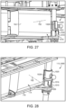
- the at least one battery compartment 114 includes a first battery compartment 114a sized and shaped to receive the first battery 162a and a second battery compartment 114b sized and shaped to receive the second battery 162b. Further details regarding an example form of the latch mechanism 115 are provided below with reference to Figs. 26-28 .
- each arm 120 generally includes an inward end portion 122 connected with the chassis 110 and an opposite outward end portion 124, and a body portion 123 extends between and connects the inward end portion 122 and the outward end portion 124.
- a rotor 126 mounted to the outward end portion 124 of each arm 120 is a rotor 126 operable to generate lift for the UAV 100 under control of the control system 150.
- the rotor 126 generally includes a propeller blade 128 and a motor 127 configured to rotate the blade 128 to generate lift under control of the control system 150, and may further include an electronic control system (ECS).
- ECS electronice control system
- the UAV 100 includes four arms 120. It is also contemplated that the UAV 100 may include more or fewer arms 120.
- the landing apparatus 130 generally includes a plurality of legs 132.
- Each leg 132 has an upper end portion connected with the chassis 110, and extends downward to a foot 134.
- one or more of the feet 134 may have a shoe mounted thereon, for example as described below with reference to Figs. 18-20 .
- Each foot 134 includes a heel 135 connected with the leg 132 and a toe 136 extending from the heel 135.
- the landing apparatus 130 is electrically connected with the control system 150 and/or the power supply 160 such that the power supply 160 can be charged via the landing apparatus 130.
- each leg 132 includes a contact surface 137 that is electrically connected with the power supply 160 via a corresponding electrical conduit 138.
- the contact surfaces 137 are defined by the feet 134, and each leg 132 is formed of an electrically conductive material and defines the electrical conduit 138. It is also contemplated that the contact surfaces 137 and conduits 138 may be provided in another form. As one example, the contact surfaces 137 may be provided as contact pads that are mounted to the feet 134, and the electrical conduits may be provided as wires that run from the contact pads to the respective points of connection with the control system 150 and/or power supply 160.
- an outer perimeter 139 is defined about the heels 135 of the feet 134, and a central axis 131 of the landing apparatus 130 is defined at a center of the perimeter 139. While other forms are contemplated, in the illustrated embodiment, the landing apparatus central axis 131 is generally coincident with the UAV central axis 101.
- a first axis X and a second axis Y that meets the first axis X at the central axis 131 such that the axes X, Y, 131 are mutually orthogonal.
- each toe 136 extends from the corresponding heel 135 in a direction generally toward the origin point at which the axes X, Y, 131 meet.
- each foot 134 and each toe 136 is contained within the outer perimeter 139.
- the feet 134 may be contained within the outer perimeter 139 in another configuration.
- each foot 134 may extend from the heel 135 to the toe 136 in a direction generally toward the first axis X, or in a direction generally toward the second axis Y.
- an effective diameter d130 of the landing apparatus 130 is defined between the radially-outer sides of the heels 135.
- each toe 136 extends from the corresponding heel 135 in a direction generally away from the origin point.
- each foot 134 extends beyond the outer perimeter 139 defined by the heels 135.
- the feet 134 may extend beyond the outer perimeter 139 in another configuration.
- each foot 134 may extend from the heel 135 to the toe 136 in a direction generally away from the first axis X, or in a direction generally away from the second axis Y.
- an effective diameter d130' of the landing apparatus 130 is defined between the radially-outer sides of the toes 136. Due to the differing orientations of the feet 134, the effective diameter d130' of the outward-facing arrangement illustrated in Fig. 5b is greater than the effective diameter d130 of the inward facing arrangement illustrated in Fig. 5a .
- the support structure 140 is mounted to the chassis 110, and generally includes an apex region 142 and a plurality of struts 144 extending between the apex region 142 and the arms 120.
- the apex region 142 may define a seat 143 sized and shaped to receive an outward-facing ranging-and-detection device 154a of the control system 150.
- Each strut 144 includes an outer end portion 145, an inner end portion 147, and a strut body 146 extending between and connecting the outer end portion 145 and the inner end portion 147.
- Each outer end portion 145 is connected to the inner end portion 122 of a corresponding one of the arms 120, and the inner end portions 147 are joined to one another at the apex region 142.
- the struts 144 are provided as two pairs of struts 144, with each pair of struts 144 defining a corresponding and respective arch 141. It is also contemplated that the struts 144 may meet at the apex region 142 in another manner.
- the apex region 142 may be provided as an annular apex region to which each inner end portion 147 is coupled (e.g., by welding).
- each strut body 146 is curved. It is also contemplated that one or more of the strut bodies 146 may be straight.
- Each strut body 146 may include one or more openings 148, one or more of which may be defined in part by a reinforcing rib 149.
- the openings 148 may serve to reduce the weight of the support structure 140 while the reinforcing ribs 149 serve to maintain the structural integrity of the support structure 140. Further details regarding the support structure 140 and the function thereof are provided herein.
- the thrust generated by operation of the rotors 126 can generate significant bending moments on the chassis 110. More particularly, these bending moments generally urge the outer portions of the chassis 110 (e.g., the locations at which the inward end portions 122 are connected to the chassis 110) toward the vertical axis 101. In the illustrated UAV 100, however, these bending moments are counteracted by the support structure 140, such that the support structure 140 provides additional structural rigidity to the chassis 110. As a result, the chassis 110 experiences less stress and strain, each of which can lead to unwanted fatigue and potential failure.
- the control system 150 generally includes a controller 152, one or more ranging-and-detection devices (RADs) 154, and a sensor array 156, and may further include one or more wireless communication devices 158.
- the control system 150 is in communication with the rotors 126 and is connected with the power supply 160 such that the controller 152 is operable to control the motors 127 to generate lift to fly the UAV 100.
- the control system 150 may be configured to control the rotors 126 to control the flight envelope of the UAV 100.
- the control system 150 may be configured to provide for protection of the flight envelope by avoiding obstacles, for example using the ranging-and-detection device(s) 154.
- the control system 150 may further be in communication with the auxiliary system(s) 170 to receive information from and/or control operation of the auxiliary system(s) 170.
- the ranging-and-detection devices 154 may include an outward-facing ranging-and-detection device 154a operable to sense obstacles in the flight path of the UAV 100 and/or a downward-facing ranging-and-detection device 154b operable to sense a distance between the UAV 100 and the ground.
- the outward-facing ranging-and-detection device 154a may be mounted in the seat 143 defined by the apex region 142 of the support structure 140, and may be utilized to aid in providing flight envelope protection for the UAV.
- the downward-facing ranging-and-detection device 154b may be mounted to the underside of the chassis 110.
- Each of the ranging-and-detection devices 154 may, for example, be provided as radar-type, optical camera devices, infrared detection devices, or LIDAR-type ranging-and-detection devices.
- optical and infrared detection devices may employ the use of active emitters, such as visible-spectrum searchlights, and non-visible spectrum lights.
- a ranging-and-detection device 154 may utilize binocular stereo vision technology.
- the sensors of the sensor array 156 may be of any type typical to unmanned aerial vehicles, and the information generated by the sensors may be used to aid in the control of the UAV 100 and/or other vehicles on the ground or in the air.
- the sensor array 156 may include an inertial sensor 156a, a gyroscopic sensor 156b, and/or a global positioning system (GPS) chip 156c.
- the inertial sensor 156a may, for example, take the form of a gyroscopic sensor or an accelerometer.
- the sensor array 156 may include an altitude sensor operable to sense the current altitude of the UAV 100.
- the sensor array 156 may include a battery level sensor operable to sense the charge level of the batteries 162.
- the sensor array 156 may include one or more of an Automated Dependent Surveillance Broadcast (ADSB) sensor, legacy 4056 aviation transponder sensors, Terminal Collision and Avoidance System (TCAS) sensors, Enhanced Ground Proximity Warning Device (EGPWS) sensors, and/or laser-gyroscope sensors.
- ADSB Automated Dependent Surveillance Broadcast
- TCAS Terminal Collision and Avoidance System
- EGPWS Enhanced Ground Proximity Warning Device
- laser-gyroscope sensors the sensor array 156 may include one or more of a magnetometer, a barometer, and/or an airspeed sensor.
- the sensor array 156 may additionally or alternatively include one or more of current sensors, one or more voltage sensors, and/or one or more temperature sensors.
- the wireless communication device(s) 158 facilitate communication between the controller 152 and one or more external devices 190.
- one or more of the wireless communication device(s) 158 may be provided as a radio frequency (RF) wireless communication device 158a configured to facilitate communication between the control system 150 and the external device 190 via radio frequency electromagnetic radiation.
- RF wireless communication device 158a may be configured to communicate over the 915 MHz band.
- an RF wireless communication device 158a may be configured to communicate over the 2.4 GHz band (e.g., WiFi).
- the wireless communication device(s) 158 may include a Wi-Fi chip 158b operable to facilitate communication between the control system 150 and the external device 190 via Wi-Fi wireless communication protocols. In certain embodiments, the wireless communication device(s) 158 may include a Bluetooth chip 158c operable to facilitate communication between the control system 150 and the external device 190 via Bluetooth wireless communication protocols. In certain embodiments, the wireless communication device(s) 158 may include a cellular network communication device 158d. It is also contemplated that the wireless communication device(s) 158 may include one or more wireless communication devices of another form.
- the onboard power supply 160 includes a plurality of batteries 162, including at least a first battery 162a and a second battery 162b.
- Each battery 162 is configured for sliding insertion into the corresponding one of the battery compartments 114 and to engage the latch 115 such that the latch 115 lockingly engages the battery 162 when the battery 162 is fully inserted.
- the batteries 162 may be interchangeable such that each battery 162 is operable to be inserted to each battery compartment 114.
- the batteries 162 may be connected with the control system 150 such that the control system 150 is operable to remain active upon removal of one battery 162 while the other battery 162 remains installed. Further details regarding the charging and replacement of the batteries 162 are provided herein.
- the control system 150 and/or the power supply 160 may be electrically connected with the landing apparatus 130 such that the UAV 100 is operable to charge the batteries 162 via the landing apparatus 130 when the landing apparatus 130 is engaged with a docking station 200 including a charging device 220. Further details regarding an example form for the docking station 200 are provided below with reference to Figs. 9-11 .
- the UAV 100 may include at least one auxiliary system 170, which may be electrically connected and/or otherwise in communication with the control system 150.
- the auxiliary system(s) 170 may, for example, be installed to the underside of the chassis 110.
- the auxiliary system(s) 170 may include at least one additional battery compartment 114 to which an additional battery 162 may be installed to increase the time that the UAV is operable to remain airborne.
- the auxiliary system(s) 170 may include a surveillance device 172 (e.g., a camera) by which the UAV 100 can surveil an area.
- the auxiliary system(s) 170 may include an emergency descent device 174, such as a parachute.
- the auxiliary system(s) 170 may include a carriage 180 operable to hold a load (e.g., a package) to be carried and/or delivered by the UAV 100.
- the auxiliary system(s) 170 may include a winch mechanism 300 operable to raise and lower loads. Further details regarding exemplary auxiliary systems 170 are provided herein.
- the illustrated carriage 180 is mounted to the underside of the chassis 110, and generally includes a first grip 181, a second grip 184, and a motor 188 operable to cause movement of the second grip 184.
- a receiving space 189 is defined between the grips 181, 184, and is operable to receive a load such as a package to be carried and/or delivered by the UAV 100.
- the first grip 181 includes a first grip pad 182 and a pair of arms 183 to which the first grip pad 182 is mounted.
- the second grip 184 includes a second grip pad 185 that is mounted to a pair of pivot arms 186 and a retention arm 186'.
- the pivot arms 186 are pivotably attached to a mounting bracket 187 such that the second grip 184 is pivotable in each of a capturing direction and a releasing direction, and the retention arm 186' is engaged with the motor 188 via a carriage lock mechanism 1100 that selectively prevents pivoting of the retention arm 186'.
- the carriage lock mechanism 1100 is configured to selectively lock the second grip 184 in a capturing position, and to selectively release the second grip 184 for pivoting to a releasing position.
- Pivoting of the second grip 184 in the capturing direction causes contraction of the receiving space 189 such that the load can be captured between the grips 181, 184. Pivoting of the second grip 184 in the releasing (e.g., from the capturing position toward the releasing position) direction causes expansion of the receiving space 189 such that the load can be released from the carriage 180.
- release of the load may simply cause the load to drop under freefall conditions. In other embodiments, such as those that include the winch mechanism 300, release of the load may cause a controlled descent of the load under control of the winch mechanism 300, for example as described below with reference to Figs. 15 and 16 .
- the first grip 181 provides a mechanical anchor point against which the load can by urged by the second grip 184, and is not controlled by the control system 150.
- the first grip 181 may be operable to move under control of the control system 150.
- the first grip 181 may be operably coupled with the motor 188 such that the motor 188 is operable to cause or permit pivoting of the first grip 181.
- the carriage 180 may include a second motor, and movement of the first grip 181 may be controlled by such a motor.
- the illustrated second grip 184 is configured to pivot under control of the motor 188, it is also contemplated that expansion and contraction of the receiving space 189 may be provided in another manner.
- the second grip 184 may be provided with a rack-and-pinion device that causes the motor 188 to linearly drive the second grip 184 and/or the first grip 181 for expansion and contraction of the receiving space 189.
- a docking station 200 illustrated therein is a docking station 200 according to certain embodiments, which in the illustrated form is provided as a charging station 200.
- the charging station 200 generally includes a nest 210 and a charging device 220 mounted in the nest 210, and may further include a base 202 to which the nest 210 is mounted.
- the nest 210 aids in aligning the UAV 100 during landing, and the charging device 220 is operable to charge the onboard power supply 160 via the landing apparatus 130.
- the illustrated device is provided as a charging station 200 that includes the charging device 220, it is also contemplated that the charging device 220 may be omitted, resulting in a non-charging docking station 200.
- the nest 210 has a central axis 211, an upper portion 212, and a lower portion 214, and is defined by at least one sidewall 219 that is angled or curved relative to the central axis 211 such that the upper portion 212 is larger in diameter than the lower portion 214.
- the upper portion 212 defines an upper opening 213 having an upper opening diameter d213 that is greater than the landing apparatus effective diameter d130.
- the upper opening diameter d213 may, for example, be in a range of 50% larger to 200% larger than the landing apparatus effective diameter d130.
- the lower portion 214 may include a lower surface 215 having a lower surface diameter d215.
- the lower surface diameter d215 may be less than the landing apparatus effective diameter d130 such that the landing apparatus 130 cannot fit within the lower surface 215, and instead must contact the inner surface of the sidewall 219. In other embodiments, the lower surface diameter d215 may be greater than the landing apparatus effective diameter d130 such that the landing apparatus 130 is capable of fitting onto the lower surface 215.
- the illustrated nest 210 has a lower surface 215, it is also contemplated that the nest 210 may instead come to a point. As described herein, it is also contemplated that the lower surface 215 may be omitted such that the bottom of the nest 210 is at least selectively open to permit access to the underside of the chassis 110, for example as described below with reference to Fig. 21 .
- the nest 210 is defined by a single frustoconical sidewall 219 that defines an oblique angle ⁇ 219 relative to the central axis 211. It is also contemplated that the nest 210 may have another configuration. As one example, the nest 210 may instead be defined by a plurality of planar, trapezoidal or triangular sidewalls that are joined such that the smaller ends define the lower portion 214 and the larger ends define the upper portion 216. Additionally or alternatively, the one or more sidewalls 219 may be curved relative to the central axis 211.
- the oblique angle ⁇ 219 is greater than 45° such that the nest 210 expands relatively rapidly along the central axis 211. In other forms, the oblique angle ⁇ 219 may be less than 45° such that the nest 210 expands relatively slowly along the central axis 211. In further embodiments, the central angle ⁇ 219 may be about 45° (e.g., from 40° to 50°).
- the charging device 220 includes a first contact pad 222 and a second contact pad 224, and the contact pads 222, 224 are electrically isolated from one another.
- one or more electrically insulating regions 223 may be provided between the contact pads 222, 224.
- the contact pads 222, 224 are provided on the inner surface of the sidewall(s) 219, and do not extend to the lower surface 215.
- one or both of the contact pads 222, 224 may extend onto the lower surface 215.
- the contact pads 222, 224 may be provided entirely on the lower surface 215.
- the charging device 220 includes or is configured for connection with a power source 204, for example via a plug 229.
- the charging device 220 may include the power source 204, such as in embodiments in which the power source 204 is provided in the form of a battery, a generator, a solar panel, or another form of power source that can be provided with the charging station 200.
- the charging device 220 may be configured for connection with the power source 204, such as in embodiments in which the power source 204 is provided as line power or the battery of a vehicle to which the charging station 200 is mounted.
- the charging device 220 When connected with the power source 204, the charging device 220 is operable to generate a voltage differential across the first contact pad 222 and the second contact pad 224 such that the UAV is operable to draw electrical power from the charging device 220.
- the charging device 220 may further include one or more sensors. As one example, one or more sensors may be used to determine when to start charging the UAV 100. As another example, one or more sensors may be used to regulate the rate of charge according to the needs of the batteries 162. As another example, one or more sensors may be used to stop charging and transition to a battery-maintenance function at the appropriate time.
- the UAV 100 is operable to land within the nest 210.
- the UAV 100 may land in the nest 210 under remote control of the user.
- the control system 150 may be programmed to autonomously land the UAV 100 within the nest 210.
- the charging station 200 and/or the nest 210 may include a landing assistance device 206. While the illustrated landing assistance device 206 is provided within the nest 210, it is also contemplated that the landing assistance device 206 may be provided at another location having a known position and/or orientation relative to the nest 210.
- the landing assistance device 206 may include active features.
- the landing assistance device 206 may include one or more beacons that provide electromagnetic homing signals (e.g., radio signals, infrared signals, visible light signals, or signals of other wavelengths).
- the UAV 100 may be configured to receive such homing signals (e.g., via one or more of the sensors of the sensor array 156), and the control system 150 may be programmed to land in the nest 210 based upon such homing signals.
- the landing assistance device 206 may include passive features.
- the landing assistance device 206 may include a barcode that provides position information to the UAV 100.
- the sensor array 156 may include a camera or other optical detector operable to provide to the control system 150 information relating to the passive feature(s), and the control system 150 may be programmed to land in the nest 210 based upon the position and/or orientation information provided by the barcode.
- the barcode may be provided as a two-dimensional barcode, such as a Quick Response (QR) code or another form of two-dimensional barcode.
- QR Quick Response
- such forms of the landing assistance device 206 may aid the UAV 100 in landing in a given orientation.
- the orientation information may aid the UAV in landing in an orientation in which each of the first leg 132 and the second leg 132 is in contact with the appropriate one of the contact pads 222, 224.
- the illustrated docking station 200 may provide for certain advantages over such prior art UAV base stations.
- such prior art landing pads typically require that the control of the UAV be precise so as to land the UAV at a central position on the landing pad.
- the upper opening diameter d213 is greater than the landing apparatus effective diameter d130, and the nest 210 tapers or curves inward from this larger diameter to a smaller diameter. It may be the case that the UAV 100 is off-center during its initial contact with the nest 210.
- the UAV central axis 101 and/or the landing apparatus central axis 131 may be offset from the nest central axis 211.
- the tapered or curved sidewall(s) 219 will urge the UAV 100 toward the central axis 211 of the nest 210 as the UAV 100 descends.
- the upper opening 213 provides the UAV with a larger target area or strike zone that can be hit during the landing process, while the tapered or curved sidewall(s) 219 ensure that the final position of the UAV 100 is substantially centered.
- the docking station 200 may obviate the need for tight controls and heightened precision during the final approach.
- the landing apparatus 130 there is an acceptable margin of error in centering of the UAV 100. Should the acceptable margin of error be exceeded, one or more of the feet 134 will land outside of the nest 210, resulting in a failed landing and potential damage to the UAV 100.
- this margin of error corresponds to the difference between the landing apparatus effective diameter d130 and the upper opening diameter d213. For a nest 210 having a given upper opening diameter d213, one manner in which the acceptable margin of error can be increased is by decreasing the landing apparatus effective diameter d130.
- each leg 132 includes a contact surface 137 that is connected with the power supply 160 via an electrical conduit 138.
- each of the contact pads 222, 224 is in contact with one or more of the contact surfaces 137.
- the charging device 220 is electrically connected with the power supply 160 via the contact surfaces 137 and the electrical conduits 138.
- the contact surfaces 137 are defined by the feet 134, which are provided with an inward-facing arrangement such as that shown in Fig. 5a .
- inward-facing arrangements for the landing apparatus 130 may have the further advantage of increasing the area of contact between each foot 134 and the corresponding contact pad 222, 224.
- the contact surfaces 137 may be defined on the heels 135, which may be angled or curved so as to conform more closely to the geometry of the contact pads 222, 224.
- increasing the area of contact between the contact surfaces 137 and the contact pads 222, 224 facilitates transmission of electrical current by reducing the electrical resistance at the interface between the contact surfaces 137 and the contact pads 222, 224, thereby increasing the efficiency and rapidity of the charging process.
- the illustrated winch mechanism 300 generally includes a mounting bracket 302, a reel 310 rotatably mounted to the mounting bracket 302, a motor 320 operable to rotate the reel 310, a severing device 330 mounted to the mounting bracket 302, a line 340 mounted to the reel 310 and extending through the severing device 330, and a sensor array 350 operable to sense various operating parameters of the winch mechanism 300, and may further include an attachment device 360 attached to a free end 342 of the line 340.
- the winch mechanism 300 is in communication with the control system 150, and is operable to raise and/or lower a load under the control of the control system 150.
- the winch mechanism 300 may be mounted to the chassis 110 in the vicinity of the carriage 180 such that the winch mechanism 300 is operable to control the descent of a load upon release of the load by the carriage 180.
- the reel 310 is rotatably mounted to the mounting bracket 302, and is operably connected with a motor shaft 322 of the motor 320 such that the motor 320 is operable to control rotation of the reel 310 about a rotation axis 311.
- the reel 310 includes a circumferential channel 312 in which the line 340 is wound onto the reel 310. While other forms are contemplated, in the illustrated form, the winch mechanism 300 is mounted to the chassis 110 with the reel 310 in a horizontal orientation such that the rotation axis 311 is a vertical rotation axis.
- the illustrated reel 310 is provided as a two-piece reel, and includes a base portion 314 and a cover portion 316, each of which partially defines the circumferential channel 312.
- the base portion 314 includes a circumferential ridge 315
- the cover portion 316 includes a circumferential groove 313 that faces an apex of the ridge 315, thereby defining a narrow, somewhat tortuous passage 317 of the circumferential channel 312.
- the passage 317 connects a radially inner portion 318 of the channel 312 with a radially outer portion 319 of the channel 312.
- the inner portion 318 has an inner portion width w318, the passage 317 has a passage width w317 less than the inner portion width w318, and the outer portion 319 tapers inward from a maximum outer portion width w319 to the passage width w317.
- the passage 317 may aid in discouraging tangling of the line 340 as the line 340 is unspooled from the reel 310.
- the motor 320 includes a motor shaft 322, and is operable to control rotation of the motor shaft 322.
- the motor shaft 322 is coupled with the reel 310 such that the motor 320 is operable to control rotation of the reel 310.
- the motor shaft 322 is directly coupled with the reel 310 and extends along the rotational axis 311.
- the motor shaft 322 may be indirectly coupled with the reel 310, for example via one or more gears that cause rotation of the reel 310 in response to rotation of the motor shaft 322.
- Rotation of the motor shaft 322 and the reel 310 in a first direction causes the line 340 to unwind from the reel 310, thereby causing the free end 342 of the line 340 to descend under the force of gravity.
- Rotation of the motor shaft 322 and the reel 310 in a second direction opposite the first direction causes the line 340 to wind onto the reel 310, thereby causing the free end 342 of the line 340 to raise.
- the first direction may alternatively be referred to as the line lowering direction
- the second direction may alternatively be referred to as the line raising direction.
- the illustrated reel 310 discourages the generation of such tangles. More particularly, the ridge 315 retains the majority of the slackened portion of the line 340 confined within the inner portion 318 of the channel 312, while the passage 317 permits the line 340 to pay out at the appropriate speed. As a result, the line 340 does not unspool so quickly as to risk the generation of tangles.
- the severing device 330 is in communication with the control system 150 and is operable to sever the line 340.
- the severing device 330 generally includes an armature 332 and a heating tube 334 passing through the armature 332.
- the armature 332 is pivotably mounted to the mounting bracket 302 for movement between an actuated position and a deactuated position, and may be biased toward the deactuated position by a biasing member.
- the pivotal range of the armature 332 may be limited by a stop arm 303 of the mounting bracket 302.
- the line 340 passes through the heating tube 334, which includes a heating coil 335 in communication with the control system 150.
- the heating coil 335 Upon receiving an appropriate severing signal from the control system 150, the heating coil 335 generates a heat sufficient to burn and/or melt the through line 340, thereby severing the line 340. It is also contemplated that the severing device 330 may sever the line in another manner, such as by employing a blade that moves to cut the line 340 upon receiving the severing signal from the control system 150. However, it has been found that the use of a heating coil 335 to melt and/or burn the line may provide certain advantages, such as reducing the number of moving parts and obviating the possibility of an inadvertent severing of the line 340.
- the line 340 includes a wound portion 341 that is wound about the reel 310, and extends through the severing device 330 to the free end 342, which is coupled with the attachment device 360.
- rotation of the reel 310 in the line raising direction winds the line 340 onto the reel 310 and raises the free end 342, and rotation of the reel 310 in the line lowering direction unwinds the line 340 from the reel 310 and lowers the free end 342.
- the line 340 is formed of a material that is sufficiently durable to support loads of a predetermined weight while remaining susceptible to melting and/or burning by the heating coil 335.
- the line 340 may be formed of nylon, polyvinylidene fluoride (PVDF), polyethylene, and/or ultra-high molecular weight polyethylene (UHMWPE), and may be provided as monofilament, braided, or another form.
- PVDF polyvinylidene fluoride
- UHMWPE ultra-high molecular weight polyethylene
- the sensor array 350 is in communication with the control system 150, and includes a rotary position sensor 354 and a load sensor 352, each of which may be mounted to the mounting bracket 302.
- the rotary position sensor 354 is associated with the reel 310 and is configured to provide the control system 150 with information relating to the angular position of the reel 310.
- the rotary position sensor 354 may, for example, be provided as a magnetic rotary sensor.
- the control system 150 may determine that the load has dropped approximately 6.28 meters. As described herein, this information can be compared with information generated by the downward-facing ranging-and-detection device 154b to determine how far the load is from the ground or other designated delivery surface.
- the load sensor 352 is associated with the armature 332 of the severing device 330 such that the load sensor 352 is operable to distinguish between the actuated and deactuated positions of the armature 332. As described herein, these positions respectively correspond to loaded and unloaded conditions of the winch mechanism 300 such that the control system 150 is operable to determine whether the winch mechanism 300 is supporting a load based upon the information received from the load sensor 352.
- the load sensor 352 is provided as a snap action mechanical switch or microswitch. It is also contemplated that the load sensor 352 may be provided as another form of sensor operable to sense the actuated/deactuated position of the armature 332, such as an optical switch, a magnetic switch, or a Hall effect switch or sensor.
- the attachment device 360 of the illustrated embodiment is provided in the form of a gravity hook 360 that is coupled (e.g., tied) to the free end 342 of the line 340, which may pass through an aperture 361 formed in the gravity hook 360.
- a load 402 to be carried and released by the gravity hook 360 the load 402 including a ring 403 by which the load 402 can be loaded onto the gravity hook 360.
- the ring 403 may comprise a portion of an attachment mechanism 404 configured to facilitate the attachment of the load 402 to the gravity hook 360.
- the attachment mechanism 404 may further comprise a base portion 405 configured for coupling to the load 402.
- the attachment mechanism 404 may be configured for adhering to the load 402.
- the ring 403 may be coupled to an upper side of the base portion 405, and the lower side of the base portion 405 may comprise an adhesive region 406 operable to secure the base portion 405 to the load 402.
- the adhesive region 406 may be covered by a protective film, and the act of attaching the attachment mechanism 404 to the load 402 may comprise removing the protective film to thereby expose the adhesive region 406, and placing the adhesive region 406 in contact with the load 402 to thereby couple the attachment mechanism 404 to the load 402.
- the attachment mechanism 404 may be coupled to the load 402 in an additional or alternative manner, such as via one or more tethers 407 that wrap about at least a portion of the load 402.
- the attachment mechanism 404 may be mounted to the load 402 without requiring further modification of the load 402, which may simplify the attachment process and/or protect the load 402 from potentially destructive modification.
- the gravity hook 360 generally includes a hook-shaped body 362 defining a hook recess 363 and a channel 369.
- a lever 364 is pivotably mounted to the body 362, and an upper side of the lever 364 defines a ramp 365.
- the lever 364 includes a first end portion 364a pivotably coupled to the body 362 and an opposite second end portion 364b that projects into the channel 369.
- the lever 364 is pivotable relative to the body 362 between a substantially horizontal upper position (illustrated) and a substantially vertical lower position, and the channel 369 accommodates the second end portion 364b during at least a portion of this movement such that the second end portion 364b is positioned in the channel 369 when in at least one of the upper position or the lower position.
- the second end portion 364b projects into the channel 369 at all times such that the channel 369 at all times restricts lateral movement of the second end portion 364b.
- the lever 364 is biased toward the upper position by a biasing member 366, which in the illustrated form, is provided in the form of a torsion spring.
- the biasing member 366 may be provided in another form, such as one that includes a compression spring, an extension spring, an elastic member, or one or more magnets.
- the load 402 may be loaded onto the gravity hook 360 by passing the tip of the hook through the ring 403 such that the ring 403 engages the lever 364 and urges the lever 364 to its lower position against the force of the biasing member 366.
- a portion of the ring 403 is seated in the hook recess 363 and maintains the lever 364 in its lower position.
- the force of the biasing member 366 is substantially side-to-side, and is insufficient to drive the lever 364 to its upper position against the weight of the load 402.
- the load 402 may then be delivered to a designated delivery surface as described in further detail below.
- the UAV 100 may be operated to deliver a load 402, such as a package, to a destination or delivery zone.
- the load may be attached to the winch mechanism 300 via the attachment device 360.
- the load 402 may also be loaded onto the carriage 180 or a similar device. It is also contemplated that the carriage 180 may be omitted, and that the load may be borne by the winch mechanism alone 300.
- the UAV 100 may then be operated, either autonomously or under control of a user, to fly to the destination.
- the control system 150 may operate the carriage motor 188 to release the load 402 from the carriage 180, thereby causing the load 402 to drop slightly until the line 340 becomes taut.
- the severing device armature 332 pivots to its actuated position, thereby actuating the load sensor 352 and indicating to the control system 150 that the load is being borne by the winch mechanism 300.
- the control system 150 may then operate the winch mechanism 300 to lower the load 402 to the ground or other surface, for example as described below with reference to Figs. 15 and 16 .
- the gravity hook 360 disengages as described above, thereby releasing the weight of the load 402 from the line 340.
- the armature 332 pivots to its deactuated position, thereby deactuating the load sensor 352 and indicating to the control system 150 that the load 402 has been delivered.
- the control system 150 may operate the motor 320 to rotate the reel 310 in the line raising direction to retract the line 340.
- the line 340 becomes tangled, caught, or otherwise prevented from operating as designed.
- the line 340 may become tangled on itself, or caught on an obstacle such as a tree or fence.
- the current drawn by the motor 320 may spike, or the sensor array 156 may indicate an unexpected jerk in the position of the UAV 100, each of which may be interpreted as a fault condition relating to the line 340.
- the control system 150 may transmit the severing signal to the severing device 330, thereby causing the severing device 330 to sever the line 340.
- the severing signal may be provided as a voltage sufficient to cause the heating coil 335 to heat to a temperature sufficient to melt and/or burn at least a portion of the line 340 within the tube 334.
- a process 400 that may be performed using a UAV to deliver a delivery load 402 to a destination such as a delivery zone 490.
- Blocks illustrated for the processes in the present application are understood to be examples only, and blocks may be combined or divided, and added or removed, as well as re-ordered in whole or in part, unless explicitly stated to the contrary. Unless specified to the contrary, it is contemplated that certain blocks performed in the process 400 may be performed wholly by one or more components of the UAV, or that the blocks may be distributed among one or more of the elements and/or additional devices or systems that are not specifically illustrated in Figs. 1-14 .
- the process 400 generally includes a loading procedure 410, an approach procedure 420, a ranging procedure 430, a release procedure 440, a delivery procedure 450, and a line retracting procedure 460, and may further include a line severing procedure 470 and/or a return procedure 480.
- the loading procedure 410 generally involves loading the delivery load 402 onto the UAV 100
- the approach procedure 420 generally involves approaching a delivery zone 490 having a designated delivery surface 491
- the ranging procedure 430 generally involves determining a distance between the UAV 100 and the designated surface 491
- the release procedure 440 generally involves releasing the load 402 from the carriage 180.
- the delivery procedure 450 generally involves delivering the load 402 to the delivery surface 491 using the line 340
- the line retracting procedure 460 generally involves retracting the line 340
- the line severing procedure 470 generally involves severing the line 340
- the return procedure 480 generally involves returning the UAV 100 to a base station or a docking station.
- the loading procedure 410 generally involves loading a delivery load 402 such as a parcel or package onto the UAV 100 such that the UAV 100 is operable to carry the load 402.
- the loading procedure 410 may, for example, be performed at a base station, which may be static (e.g., provided to a building) or mobile (e.g., provided to a delivery truck).
- the loading procedure 410 may, for example, be performed by one or more of delivery personnel, the owner and/or operator of the UAV 100, or other personnel.
- the loading procedure 410 includes block 412, which generally involves attaching a delivery load 402 to a line 340 of a winch mechanism 300 of a UAV 100.
- block 412 generally involves attaching the delivery load 402 to the free end 342 of the line 340, for example using the attachment device 360.
- block 412 may involve attaching the gravity hook 360 to the ring 403 of the load 402 such that the winch mechanism 300 is operable to raise and lower the load 402 by rotating the reel 310 in the line raising direction and the line lowering direction.
- the loading procedure 410 may further include block 414, which generally involves mounting the delivery load 402 in the carriage of the UAV.
- block 414 generally involves mounting the delivery load 402 into the carriage 180 of the UAV 100.
- mounting the load 402 to the carriage 180 may reduce the amount by which the load 402 can sway during transport, which may facilitate the control of the UAV 100 during subsequent procedures and blocks.
- the loading procedure 410 may further include block 416, which generally involves providing the control system 150 with information relating to the location of the delivery zone 490.
- the information may be provided by the load 402 itself.
- the load 402 or a sticker attached thereto may include (e.g., have printed thereon) the information, either in plaintext or in an encoded form (e.g., a barcode), and the control system 150 may derive such information via an optical scanner of the sensor array 156.
- the load 402 may be provided with a radio frequency identification (RFID) tag having the information encoded thereon, and the control system 150 may derive such information via an RFID reader of the sensor array 156.
- RFID radio frequency identification
- the information may be provided in another manner.
- the delivery personnel may upload the information to the control system 150 via an external device 190 (e.g., a mobile device) in communication with the control system 150, such as via the one or more wireless communication devices 158.
- the process 400 may continue to the approach procedure 420, which generally involves approaching the delivery zone 490.
- the approach procedure 420 may be performed by and/or under the control of a user or external control system, such as the external device 190.
- the approach procedure 420 may be performed by and/or under the control of the control system 150.
- the approach procedure 420 includes block 422, which generally involves operating one or more rotors of the UAV to generate lift.
- block 422 involves supplying, by the control system 150, power from the power supply 160 to the rotor motors 127, thereby causing the motors 127 to rotate the propellers 128 to generate the lift.
- the UAV 100 will rise from the ground, loading surface or docking station.
- the approach procedure 420 includes block 424, which generally involves navigating the load-carrying UAV to the delivery zone to which the load is to be delivered.
- block 424 generally involves navigating the UAV 100 to the delivery zone 490 to which the load 402 is to be delivered.
- the navigating may be performed using GPS information, such as GPS information provided by the GPS device 156c.
- the control system 150 may operate the outward-facing ranging-and-detection device 154a to detect and avoid obstacles in the path of the UAV 100. While certain examples have been provided regarding the navigation of block 424, it is to be appreciated that various other manners of navigating to the delivery zone 490 may occur to those having skill in the art, and may be employed without departing from the spirit of the current disclosure.
- the approach procedure 420 may further include block 426, which generally involves hovering above the designated delivery surface.
- Block 426 may, for example, be performed upon completion of the navigating in block 424, and generally involves hovering at a hover height h100 above the delivery surface 491.
- the hover height h100 may be a predetermined hover height.
- the hover height h100 may not necessarily be predetermined.
- the hovering of block 426 may, for example, be performed throughout one or more of the following procedures (e.g., the ranging procedure 430, and/or the delivery procedure 450) to maintain a substantially constant hover height h100 during the performance of such procedures.
- the process 400 may continue to the ranging procedure 430, which generally involves providing the control system with information relating to the distance between the UAV and the delivery surface. In the illustrated form, this distance corresponds to the hover height h100, which is the height at which the UAV 100 hovers above the delivery zone 490 in block 426.
- the ranging procedure 430 includes block 432, which generally involves operating the downward-facing ranging-and-detection device 154b to determine the hover height h100. In certain embodiments, the process 400 may involve adjusting the altitude of the UAV to reach a predetermined hover height h100.
- the ranging of block 432 may be performed a single time to determine the substantially constant hover height h100. It is also contemplated that the ranging of block 432 may be performed intermittently, continually, or continuously, for example in embodiments in which the UAV 100 does not necessarily maintain a constant hover height h100.
- the process 400 may include the release procedure 440, which generally involves releasing the delivery load 402 from the carriage 180.
- the release procedure 440 includes block 442, which generally involves operating the carriage motor 188 to move the second grip 184 outward under the control of the control system 150.
- the receiving space 189 expands, thereby causing the load 402 to drop a distance corresponding to the slack in the line 340.
- the load 402 is supported by the line 340 such that the line becomes taut.
- the armature 332 moves from its deactuated position to its actuated position, thereby tripping the load sensor 352 and indicating to the control system 150 that the weight of the load 402 is being carried by the line 340.
- the process 400 further includes the delivery procedure 450, which may, for example, be performed upon completion of the release procedure 440 (e.g., in embodiments in which the load 402 is mounted in the carriage 180 for transport). For example, performance of the delivery procedure 450 may begin in response to the information from the load sensor 352 indicating that the load 402 has been released from the carriage 180. In embodiments in which the UAV 100 lacks the carriage 180, the delivery procedure 450 may begin based upon one or more alternative criteria, such as a determination that the UAV 100 has reached the delivery zone 490.
- the delivery procedure 450 generally includes providing the load 402 with a controlled rate of descent v402 as the load passes through an upper zone 492 in block 452, accelerating the rate of descent v402 as the load 402 passes through an intermediate zone 494 in block 454, and reducing the rate of descent v402 as the load 402 passes through a lower zone 496 in block 456.
- the hover height h100 corresponds to the distance between the UAV 100 and the delivery surface 491. This distance may be divided into three zones through which the load 402 descends during the delivery procedure 450: an upper zone 492 in the vicinity of the UAV, a lower zone 496 in the vicinity of the delivery surface 491, and an intermediate zone 494 between the upper zone 492 and the lower zone 496.
- the control system 150 is operable to determine the free length L340 of line 340 that has been doled out, for example based upon the information received from the rotary sensor 354.
- the control system 150 may further be operable to determine which zone the load 402 currently occupies, for example based upon a comparison of the free length L340 and thresholds corresponding to each zone.
- the free length L340 is less than a first threshold length, which corresponds to a selected distance for the upper zone 492.
- the free length L340 is between the first threshold length and a second threshold length, which corresponds to a difference between the hover height h100 and a selected height for the lower zone 496.
- the free length L340 is greater than the second threshold length and less than a third threshold length, which corresponds to the hover height h100.
- the free length L340 is greater than or equal to the third threshold length.
- the zone through which the load 402 is currently passing and/or the presence of the load 402 on the delivery surface 491 can be determined based upon the free length L340 of the line 340, which in turn can be calculated by the control system 150 based upon the information received from the rotary sensor 354.
- one or more of the zones 492, 494, 496 may have a predetermined height.
- the upper zone 492 may have a height of four feet
- the lower zone 496 may have a height of five feet
- the height of the intermediate zone 494 may be defined as the hover height h100 minus the nine feet occupied by the upper zone 492 and the lower zone 496.
- the first threshold would be set to four feet (the selected height for the upper zone 492)
- the second threshold would be set to 35 feet (the difference between the hover height h100 and the selected height for the lower zone 496)
- the third threshold would be set to forty feet (the hover height h100). It should be appreciated that these examples are illustrative only, and may be selected based upon various criteria and/or parameters.
- the delivery procedure 450 includes block 452, which generally involves providing the load 402 with a controlled rate of descent v402 as the load 402 passes through the upper zone 492.
- block 452 involves operating the winch motor 320 to cause or permit the reel 310 to rotate in the line lowering direction at a controlled rate of speed.
- the controlled rate of speed may be a constant rate of speed. In other forms, the controlled rate of speed may be variable.
- controlling the rate of speed at which the reel 310 rotates controls the rate of load descent v402.
- controlling the rate of load descent v402 may involve limiting the rate of load descent v402 to a threshold velocity, such as 10 cm/s. As another example, the threshold velocity may be provided between 5 cm/s and 15 cm/s.
- block 452 may be performed to control the rate of load descent v402 for a predetermined period of time. In certain embodiments, block 452 may be performed to control the rate of descent v402 until the free length L340 reaches the first threshold length, at which point the load 402 is located at the boundary 493 between the upper zone 492 and the intermediate zone 494.
- the delivery procedure 450 also includes block 454, which generally involves accelerating the load 402 to increase the rate of load descent v402 as the load 402 passes through the intermediate zone 494.
- block 454 involves operating the winch motor 320 to cause or permit the reel 310 to rotate in the line lowering direction at a greater rate of speed than was permitted in the initial descent stage of block 452, thereby increasing the rate of load descent v402.
- block 454 may involve operating the winch motor 320 to cause or permit the load 402 to descend under essentially free-fall conditions.
- block 452 involves limiting the rate of descent v402 to an initial descent velocity
- block 454 involves limiting the rate of descent v402 to a nominal velocity greater than the initial descent velocity.
- the increased rate of descent v402 provided in block 454 increases the speed of the delivery as compared to if the entire delivery procedure 450 were limited to a lesser velocity.
- block 454 may be performed to control the rate of descent v402 from the time the free length L340 is the first threshold length until the free length L340 reaches the second threshold length, at which point the load 402 is located at a boundary 495 between the intermediate zone 494 and the lower zone 496.
- the delivery procedure 450 may also include block 456, which generally involves reducing the rate of load descent v402 as the load 402 passes through the lower zone 496.
- block 456 involves operating the winch motor 320 to cause or permit the reel 310 to rotate in the line lowering direction at a lesser rate of speed than was permitted in the intermediate descent stage of block 454, thereby reducing the rate of descent v402.
- block 454 involves limiting the rate of descent v402 to a nominal descent velocity, and block 454 involves reducing the rate of descent v402 to a landing velocity less than the nominal velocity.
- block 456 may be performed to control the rate of descent v402 from the time the free length L340 is the second threshold length until the free length L340 reaches the third threshold length, at which point the load 402 may be positioned on the delivery surface 491.
- the UAV 100 provides the load 402 with a softer landing than would be provided if the load 402 were allowed to land at the nominal speed of block 454. This soft landing may aid in reducing damage to the load 402, particularly in situations in which the load 402 is fragile.
- the process 400 may continue to the line retracting procedure 460, which generally involves retracting the line 340.
- the line retracting procedure 460 may, for example, be performed by the winch mechanism 300 under control of the control system 150.
- the line retracting procedure 460 may include block 462, which generally involves detecting delivery of the load 402.
- the gravity hook 360 may release the load 402 as described above.
- the armature 332 moves to its deactuated position, thereby altering the output of the load sensor 352 such that the load sensor 352 indicates that the load 402 has been delivered.
- block 462 may involve detecting the delivery based upon information received from the load sensor 352. It is also contemplated that block 462 may involve inferring that the load has been delivered based upon one or more additional or alternative criteria, such as the free length L340 of the line 340 meeting or exceeding the third threshold length, which may correspond to the hover height h100.
- the line retracting procedure 460 includes block 464, which generally involves operating the winch motor 320 to rotate the reel 310 in the line raising direction.
- block 464 may be performed in response to the delivery of the load 402 being detected based upon information received from the load sensor 352 in block 462.
- block 464 may involve operating the winch motor 320 until the free length L340 is zero or nominally zero.
- block 464 may involve operating the winch motor 320 to raise the line 340 at a constant retraction speed. In other forms, the retraction speed may be variable.
- the process 400 may involve the severing procedure 470, which generally involves detecting a fault condition and severing the line in response to detecting the fault condition.
- the severing procedure 470 may be performed by the severing device 330 under control of the control system 150.
- the severing procedure 470 includes block 472, which generally involves determining a fault condition.
- the fault condition may be determined based at least in part upon a spike in current drawn by the winch motor 320 during the line retracting procedure 460.
- the fault condition may be determined based at least in part upon acceleration or jerking of the UAV 100 during the line retracting procedure 460, which may be sensed by one or more sensors of the sensor array 156.
- the fault condition may be determined based at least in part upon stalling of the retraction of the line 340 during the retraction procedure.
- Such stalling may, for example, be determined when the winch motor 320 is attempting to retract the line 340 while the reel position sensor 352 indicates that the reel 310 is remaining stationary.
- there may be a time function involved with the detection of the fault condition, such as determining the fault condition only when the jerk or the stalling lasts a predetermined period of time.
- the severing procedure 470 further includes block 474, which generally involves transmitting a severing signal in response to determining the fault condition.
- block 474 involves supplying the heating coil 335 of the severing device 330 with an electric current sufficient to cause the heating coil 335 to heat to a temperature sufficient to melt and/or burn through at least a portion of the line 340 that is positioned within the tube 334.
- block 474 may involve transmitting a signal operative to cause a mechanical cutting device (e.g., a movable blade) to sever the line 340.
- a mechanical cutting device e.g., a movable blade
- the illustrated severing procedure 470 further includes block 476, which generally involves melting and/or burning the line in response to the severing signal transmitted in block 474. More particularly, the illustrated embodiment of block 476 involves heating the heating coil 335 to a temperature sufficient to melt and/or burn at least a portion of the line 340 that is positioned within the tube 334. It is also contemplated that block 476 may include severing the line 340 in another manner, for example by causing a mechanical severing device (e.g., a movable blade) to sever the line 340.
- a mechanical severing device e.g., a movable blade
- the process 400 may further include a return procedure 480, which generally involves returning the UAV 100 to a base station.
- the base station may include the above-described docking station 200.
- the base station may be the same base station at which the UAV 100 was provided with the load 402 in the loading procedure 410, while in other embodiments the base station may be a different base station.
- the base station to which the UAV 100 returns may be a static or stationary base station, such as one located at a residence or a distribution center.
- the base station to which the UAV 100 returns may be a mobile base station, such as a delivery vehicle.
- the return procedure 480 includes block 482, which generally involves navigating to the base station.
- the navigating of block 482 may be performed using the GPS chip 156c and based upon a known position of the base station.
- the control system 150 may have coordinates of the base station programmed in memory.
- the base station may be equipped with a GPS chip and a wireless communication device, and the control system 150 may receive information relating to the current or future position of the base station via the wireless communication device 158.
- the base station may be equipped with one or more beacons (e.g.
- radio frequency beacons may navigate to the base station using homing signals generated by the one or more beacons. While certain examples have been provided regarding the navigation of block 482, it is to be appreciated that various other manners of navigating to the base station may occur to those having skill in the art, and may be employed without departing from the spirit of the current disclosure.
- the return procedure 480 further includes block 484, which generally involves lowering the UAV 100 into a nest 210 of a docking station 200 provided at the base station.
- the lowering of block 484 may involve descending into the nest 210 based at least in part upon information received from the landing assistance device 206.
- the landing assistance device 206 may comprise an electromagnetic beacon (e.g., a radio frequency beacon, an infrared beacon, a visible light beacon, or a beacon using additional or alternative wavelengths), and the control system 150 may control the UAV 100 to descend into the nest 210 using positional information derived from the electromagnetic homing signal issued by the beacon.
- the landing assistance device 206 may comprise a barcode that provides the control system 150 with position and/or orientation information, and block 484 may involve lowering the UAV 100 into the nest 210 with its position and/or orientation being controlled based upon the position and/or orientation information provided by the barcode.
- the nest 210 may assist the UAV 100 in landing in a predetermined position and/or orientation. Such assistance may be provided at least in part by the landing assistance device 206 as described above. Additionally, the geometry of the nest 210 may itself aid in providing the UAV 100 with the desired position and/or orientation. For example, if the centering of the UAV 100 relative to the nest 210 is off by less than the acceptable margin of error, the sidewall(s) 219 may urge the descending UAV 100 to a centered position as described above.
- the desired position and orientation may be a position and orientation in which a first leg 132 is positioned on the first contact pad 222 and a second leg 132 is positioned on the second contact pad 224.
- the charging device 220 may begin recharging the onboard power supply 160 upon landing of the UAV 100.
- a delivery process 400 may take other forms.
- a delivery process may simply involve mounting the load 402 to the carriage 180 or a similar carriage.
- the delivery procedure 450 may simply involve releasing the load 402 from the carriage 180, such as when the UAV is at a relatively low height above the designated delivery surface 491.
- the power supply 160 may include plural batteries 162, and may be operable to receive electrical power for recharging via the landing apparatus 130. Additionally or alternatively, one or more of the batteries 162 may be replaced when the charge in the battery 162 has been reduced. An example process that involves replacing one or more of the batteries 162 will now be described with reference to Fig. 17 .
- an exemplary process 500 that may be performed using to replace one or more batteries of a UAV.
- Blocks illustrated for the processes in the present application are understood to be examples only, and blocks may be combined or divided, and added or removed, as well as re-ordered in whole or in part, unless explicitly stated to the contrary. While the blocks are illustrated in a relatively serial fashion, it is to be understood that two or more of the blocks may be performed concurrently or in parallel with one another unless specified to the contrary.
- the process 500 is described with specific reference to the example UAV 100 illustrated in Fig. 1 , it is to be appreciated that the process 500 may be performed using a UAV of similar or different configurations.
- the process 500 may begin with the UAV 100 unpowered and the power supply 160 uninstalled.
- the process 500 generally involves installing a first battery 162a, performing an initialization procedure, installing a second battery 162b, and removing the first battery 162a after installing the second battery 162b. Due to the fact that the first battery 162a is removed only after the second battery is installed, the control system 150 can remain continuously active without the necessity of repeating the initialization procedure.
- the process 500 includes block 502, which generally involves installing a first battery 162a to the chassis 110 such that the control system 150 is operable to receive electrical power from the first battery 162a.
- block 502 includes installing the first battery 162a to the first battery compartment 114.
- the first battery compartment 114a is configured to receive sliding insertion of the first battery 162a
- the latch 115 is configured to lockingly engage the first battery 162a upon sliding insertion of the first battery 162a.
- block 502 may involve slidingly inserting the first battery 162a into the first battery compartment 114a along an insertion axis 102a (e.g., a horizontal insertion axis), and engaging the latch 115 of the first battery compartment 114a to lock the first battery 162a into the first battery compartment 114a.
- the first battery 162a With the first battery 162a installed, the first battery 162a is electrically connected with the control system 150 such that the control system 150 is operable to receive electrical power from the first battery 162a.
- the process 500 also includes block 504, which generally involves performing an initialization procedure to activate the control system 150.
- the initializing of block 504 may be performed after installing the first battery in block 502, and may be performed using power drawn from the first battery 162a.
- the initialization procedure performed in block 504 may include one or more operations necessary or desired for the proper operation of the UAV 100.
- the initializing of block 504 may include powering up the control system 150 and performing any processes attendant to such powering up.
- the initializing procedure of block 504 may include calibrating one or more components of the UAV 100, such as the ranging-and-detecting device(s) 154, the accelerometer, the gyroscope, and/or the magnetometer.
- the initializing of block 504 may involve confirming the status of system communications with the UAV 100 and its ground control station. In certain embodiments, the initializing of block 504 may involve performing one or more built-in-test-equipment checks for system continuity. In certain embodiments, the initialization of block 504 may include checks of battery voltage and/or checks of lighting and auxiliary systems that may be installed.
- the process 500 may include block 506, which generally involves operating the UAV 100.
- Block 506 may be performed following performance of the initialization procedure in block 504, and the initialization procedure performed in block 504 may involve one or more operations necessary or desired for the operating of block 506.
- the operating of block 506 may be performed while the first battery 162a is installed using power drawn from the first battery 162a, thereby partially depleting the charge stored in the first battery 162a.
- the operating of block 506 may involve delivering a load 402 along the lines set above with reference to the process 400. It is also contemplated that the operating of block 506 may involve additional or alternative procedures.
- block 506 may involve operating the UAV 100 to conduct a surveillance operation.
- the process 500 also includes block 508, which generally involves installing a second battery 162b to the chassis 110 such that the control system 150 is operable to receive electrical power from the second battery 162b.
- the installing of block 508 may be substantially similar to the installing of block 502.
- the installing of block 508 may involve slidingly inserting the second battery 162b into the second battery compartment 114b along an insertion axis 102b (e.g., a horizontal insertion axis), and engaging the latch 115 of the second battery compartment 114b to lock the second battery 162b into the second battery compartment 114b.
- the control system 150 is operable to receive electrical power from the second battery 162b.
- the process 500 also includes block 510, which generally involves removing the first battery 162a.
- Block 510 may, for example, involve disengaging the latch 115 and slidingly removing the first battery 162a from the first battery compartment 114 along a removal axis.
- the removal axis may be the same as the insertion axis. In other embodiments, the removal axis may be different from the insertion axis.
- the removal of the first battery 162a in block 510 is performed after installation of the second battery 162b in block 508 such that the control system 150 is operable to remain at least partially active under power supplied by the second battery 162b upon removal of the first battery 162a.
- the control system 150 may remain partially active upon removal of the first battery 162a, for example by entering a sleep mode. In certain embodiments, the control system 150 may remain fully active upon removal of the first battery 162a.
- the process 500 also includes block 512, which generally involves continuing to operate the control system 150 under power of the second battery 162b.
- the second battery 162b is installed prior to the removal of the first battery 162a such that the control system 150 is capable of remaining at least partially active upon removal of the first battery 162a, thereby obviating the need for repeating the initialization procedure.
- the process 500 may include block 514, which generally involves replacing the first battery 162a with a third battery 162c.
- Block 514 may, for example, involve installing the third battery 162c to the first battery compartment 114 in a manner substantially similar to that in which the first battery 162a was installed to the first battery compartment 114.
- the process 500 may include block 516, which generally involves removing the second battery 162b.
- the removal of the second battery in block 516 may be performed after installation of the third battery 162c in block 514 such that the control system 150 is operable to remain powered under power supplied by the third battery 162c upon removal of the second battery 162b.
- the process 500 may include block 518, which generally involves continuing to operate the control system 150 under power of the third battery 162c while the second battery 162b is removed.
- the third battery 162c is installed prior to the removal of the second battery 162b such that the control system 150 is capable of remaining continuously powered upon removal of the second battery 162b, thereby obviating the need for repeating the initialization procedure.
- the process 500 may include block 520, which generally involves replacing the second battery with a fourth battery.
- Block 520 may, for example, involve installing the fourth battery 162d to the second battery compartment 114 in a manner substantially similar to that in which the second battery 162b was installed to the second battery compartment 114.
- the process 500 also includes block 522, which generally involves operating the UAV 100 without repeating the initialization procedure.
- the operating of block 522 may be performed with only the second battery installed (e.g., after block 508 and before block 514).
- the operating of block 522 may be performed with the second battery and the third battery installed (e.g., after block 514 and before block 516).
- the operating of block 522 may be performed with only the third battery installed (e.g., after block 516 and before block 520).
- the operating of block 522 may be performed with the third battery and the fourth battery installed (e.g., after block 520).
- blocks in the illustrated process 500 may be reordered except where noted to the contrary.
- the installation of the second battery in block 508 may be performed between the installation of the first battery in block 502 and the performance of the initialization procedure in block 504.
- installation of the second battery in block 508 may be performed between the performance of the initialization procedure in block 504 and the operating of the UAV 100 in block 506.
- the process 500 may be employed to remove or replace an installed battery while continuously powering the control system 150 such that the UAV 100 can be operated without repeating an initialization procedure that was performed earlier in the continuous operation of the control system 150.
- the initialization procedure performed in block 504 may be somewhat time-consuming and/or may require technical expertise.
- the process 500 allows for one or more batteries 162 of the UAV to be replaced while continuously operating at least a portion of the control system 150 such that the initialization procedure need not be repeated each time the power supply 160 loses charge.
- the operator may instead remove one battery 162 while another battery 162 is installed to the UAV 100 such that the control system 150 remains at least partially active, thereby obviating the need to repeat the initialization procedure.
- the process 500 may reduce the time and/or technical expertise needed to continue operation of the UAV 100. This may be particularly valuable in situations where the UAV 100 is operated via a mobile base station (e.g., a delivery vehicle), the operator of which may not necessarily have the time and/or expertise to perform the initialization procedure of block 504.
- a mobile base station e.g., a delivery vehicle
- the product line 600 includes a docking station 610 and a UAV family 620 including a plurality of UAV configurations, each of which includes a landing apparatus 630 according to certain embodiments. As described herein, each member of the UAV family 620 is operable to land in the docking station 610, and the product line 600 has associated therewith a predetermined angle ⁇ 600 that defines certain aspects of the product line 600.
- the docking station 610 is provided in the form of the above-described docking station 200, and includes a nest 210.
- the nest 210 of the docking station 200 illustrated in Figs. 9-11 is frustoconical, and the sidewall 219 thereof defines an oblique angle ⁇ 219 relative to the central axis 211 of the nest 210.
- the oblique angle ⁇ 219 is defined as the predetermined angle ⁇ 600 that is associated with the product line 600.
- the UAV family 620 includes a first UAV configuration 622 and a second UAV configuration 624 that is smaller than the first UAV configuration 622. It is also contemplated that the UAV family 620 may include additional UAV configurations, such as one or more UAV configurations larger than the first UAV configuration 622, one or more UAV configurations smaller than the second UAV configuration 624, and/or one or more UAV configurations smaller than the first UAV configuration 622 and larger than the second UAV configuration 624. One or more of the UAV configurations in the UAV family 620 may, for example, be provided along the lines of the UAV 100 described above.
- the landing apparatus 630 is substantially similar to the landing apparatus 130, and similar reference characters are used to indicate similar features.
- the illustrated landing apparatus 630 includes a plurality of legs 632 each having a corresponding foot 634, which respectively correspond to the above-described legs 132 having feet 134.
- the landing apparatus 630 includes four legs 632a-632d, each having a corresponding foot 634a-634d. It is also contemplated that more or fewer legs 632 may be utilized.
- the landing apparatus 630 further includes at least one shoe 633, and in the illustrated form includes a pair of shoes 633a, 633b.
- Each shoe 633 is attached to at least one foot 634, and in the illustrated form, each shoe 633 is attached to a corresponding pair of feet 634. More particularly, the first shoe 633a is attached to the first foot 634a and the second foot 634b, and the second shoe 633b is attached to the third foot 634c and the fourth foot 634d.
- each shoe 633 is provided as a portion of a cone such that the shoes 633 provide the lower end portion of the landing apparatus 630 with a generally frustoconical geometry.
- Each shoe 633 extends at an oblique angle relative to a central vertical axis 631 of the landing apparatus 630. More particularly, each shoe 633 defines the predetermined angle ⁇ 600 relative to the central axis 631.
- the generally frustoconical geometry defined by the shoes 633 matches the frustoconical geometry of the nest 210.
- the sizes of the landing apparatuses 630 may be scaled to match the sizes of the UAV configurations 622, 624. More particularly, the effective diameter d630 of the landing apparatus 630 of the larger first UAV configuration 622 may be greater than the effective diameter d630 of the landing apparatus 630 of the smaller second UAV configuration 624.
- the landing apparatus 630 of the first UAV configuration 622 will sit higher in the docking station 610 than the landing apparatus 630 of the second UAV configuration 624. More particularly, the shoes 633 of the first UAV configuration 622 will occupy an upper region 612 within the nest 210, and the shoes 633 of the second UAV configuration 624 will occupy a lower region 614 in the nest 210.
- the docking station 200/610 may include a charging device 220 including first and second contact pads 222, 224.
- Each contact pad 222, 224 may be positioned at least partially in the upper region 612 such that the charging device 220 is operable to charge a UAV 100 of the first UAV configuration 622 when such a UAV 100 is seated in the nest 210.
- each contact pad 222, 224 may be positioned at least partially in the lower region 614 such that the charging device 220 is operable to charge a UAV 100 of the second UAV configuration 624 when such a UAV 100 is seated in the nest 210.
- each contact pad 222, 224 may extend between the upper region 612 and the lower region 614 such that the charging device 220 is operable to charge both UAVs of the first UAV configuration 622 and UAVs of the second UAV configuration 624.
- the outer geometry of the shoes 633 generally conforms to the inner geometry of the nest 210.
- Those skilled in the art will readily recognize that such general conformity increases the area of contact between the landing apparatus 630 and the nest 210, thereby increasing the stability of a UAV 100 mounted in the docking station 200/610.
- this increased area of contact further reduces the electrical resistance at the interface between the landing apparatus 630 and the contact pads 222, 224, thereby facilitating the charging process as described above.
- the contact pads 222, 224 are electrically isolated from one another, for example by one or more insulating regions 223.
- the landing assistance device 206 may provide the UAV 100 with position and orientation information that aids the UAV 100 in landing within the nest 210.
- the position and orientation information provided by the landing assistance device 206 may be used by the control system 150 to ensure that the shoes 633 do not cross the insulating regions 223 in a manner that would electrically connect the contact pads 222, 224.
- the control system 150 may utilize the position and orientation information provided by the landing assistance device 206 to align the gaps between the shoes 633 with the insulating regions 223 such that each shoe 633 rests on a corresponding one of the contact pads 222, 224.
- the nest 210 is frustoconical, and each shoe 633 is provided as a segment of a cone. It is also contemplated that the shoes 633 may be planar, for example in embodiments in which the nest 210 is defined by a plurality of planar sidewalls 219. Moreover, while each of the illustrated shoes 633 extends between and connects a corresponding pair of the feet 634, it is also contemplated that each shoe 633 may be mounted to a single corresponding and respective foot 634.
- each UAV configuration 622, 624 may have a corresponding common platform including those components required for basic flight operations (e.g., the chassis 110, the arms 120, and the control system 150). From this common platform, one or more UAV species can be created by installing to the common platform an appropriate set of landing apparatus 130 and/or auxiliary system(s) 170.
- a first landing apparatus configuration may include shorter legs
- a second landing apparatus configuration may include longer legs
- landing apparatuses of the first and second configurations may be interchangeable such that each landing apparatus configuration is operable to be installed to the common platform for the UAV configuration.
- the landing apparatus configuration with the longer legs may further include additional battery compartments 114 operable to store additional batteries, which may increase the operational time and/or range for the UAV 100.
- the modularity of the product line 600 need not be limited to the landing apparatus 630.
- certain species within a particular UAV configuration may include the carriage 180, while the carriage 180 may be omitted from other species.
- certain species within a particular UAV configuration may include the winch mechanism 300, while the winch mechanism 300 may be omitted from other species.
- the surveillance device 172 may be included in some species and excluded from others, and different forms of surveillance device 172 may be provided for different species.
- the surveillance device 172 of one or more species may include an infrared camera, and the surveillance device 172 of one or more species may include a visible light camera.
- one or more of the auxiliary systems 170 may be configured for mounting to plural UAV configurations.
- one or more of the auxiliary systems 170 may be dedicated to a corresponding UAV configuration.
- the larger UAV configuration 622 may be capable of generating the lift required to carry a relatively heavy auxiliary system (e.g., additional batteries 162), whereas the smaller UAV configuration 624 may be unable to generate the requisite lift.
- a docking station 700 is substantially similar to the above-described docking station 200, and similar reference characters are used to indicate similar elements and features.
- the docking station 700 includes a nest 710 and may further include a charging device 720, which respectively correspond to the above-described nest 210 and charging device 220.
- the following description of the docking station 700 focuses primarily on features that are different from those described above with reference to the docking station 200, such as a cover 730 and a base plate 740.
- the nest 710 extends along a central axis 711, and includes an upper portion 712 and a lower portion 714.
- the upper portion 712 defines an upper opening 713 having an upper opening diameter d713 that is greater than the landing apparatus effective diameter d130 such that upper opening 713 is operable to receive the landing apparatus 130.
- the lower portion 714 defines a lower opening 715 having a lower opening diameter d715 that is less than the landing apparatus effective diameter d130 such that the landing apparatus 130 is inoperable to pass through the lower opening 715.
- the docking station 700 may include a charging device 720 corresponding to the above-described charging device 220.
- the charging device 720 may include a first contact pad 722 and a second contact pad 724 electrically isolated from the first contact pad 722.
- the docking station 700 may be operable to charge the power supply 160 of the UAV 100 in a manner analogous to that described above. It is also contemplated that the charging device 720 may be omitted from the docking station 700.
- the docking station 700 further includes a cover 730 operable to cover the upper end of the nest 710 to selectively enclose the upper opening 713.
- the cover 730 may be moved manually to open and close the nest 710.
- the docking station 700 may include a motor operable to move the cover 730 to open and close the nest 710.
- the cover 730 may, for example, include one or more movable panels 732.
- the panels 732 are retractable along a plane occupied by the panels 732 when the cover 730 is in its closed position.
- the panel(s) 732 may pivot between the open and closed positions thereof.
- the panel(s) 732 may be rigid.
- the panel(s) 732 may be flexible.
- the panel(s) 732 may be articulated such that the panels are capable of bending or curving. It is also contemplated that the panel(s) 732 may be replaced or supplemented by other forms of covers, such as a tarp, or that the cover 730 may be omitted.
- the docking station 700 may further include a base plate 740 operable to at least partially cover the lower opening 715.
- the base plate 740 is attached to the lower portion 714 of the nest 710 via a hinge 742. It is also contemplated that the base plate 740 may be operable to cover the lower opening 715 by swiveling side to side, or in another manner, such as those described above with reference to the manners in which the cover 730 may be operable to cover the upper opening. While other locations are contemplated, in the illustrated form, the landing assistance device 706 is mounted to the base plate 740 such that the landing assistance device 706 is accessible via the upper opening 713 when the base plate 740 is in its closed position.
- the docking station 700 may be provided to a base station 750, and may occasionally be exposed to the elements, such as rain and snow. In order to mitigate the adverse effects of these elements and to avoid entry of precipitation into the base station 750, the docking station 700 may be provided with seals, gutters, channels, drains, pumps, and/or tubes that direct the precipitation away from the nest 710.
- the base plate 740 may seal with the lower end of the nest 710 when in the closed position, and may define a funnel that leads to a tube to collect precipitation and prevent pooling of precipitation within the nest 710.
- a base station 750 including the docking station 700.
- the base station 750 includes a roof or ceiling 752 to which the docking station 700 is mounted.
- the nest 710 extends through the ceiling 752 such that the upper portion 712 is positioned above the ceiling 752 and the lower portion 714 is positioned below the ceiling 752.
- the upper opening 713 may be defined in the ceiling 752, and the nest 710 may extend downward from the ceiling 752 into a loading area 754 that is at least partially covered by the ceiling 752.
- the lower opening 715 may be defined in the ceiling 752, and the nest 710 may extend upward from the ceiling 752.
- the base station 750 may be provided as a static base station.
- the base station 750 may be a distribution center, a residence, or a place of business. It is also contemplated that the base station 750 may be provided as a mobile base station, such as a delivery vehicle.
- the loading area 754 may be provided as the trailer or stowage cabin of a delivery vehicle, such as a truck or other land vehicle, a plane or other air vehicle, or a boat or other water vehicle.
- the charging device 720 may receive power from a power supply of the base station 750.
- the charging device 720 may be connected to the line power that powers the base station.
- the charging device 720 may receive power from a battery or other power source of the mobile base station.
- one or more delivery loads 762, 764 may be disposed in the loading area 754, for example on one or more shelves 756.
- the delivery loads may include first, UAV-deliverable delivery loads 762 and second, non-UAV-deliverable delivery loads 764.
- a process 800 involves delivering a UAV-deliverable delivery load 762 from the base station 750 to a corresponding delivery zone using the UAV 100.
- Each of the UAV-deliverable delivery loads 762 is sized and shaped such that the delivery load 762 is operable to pass through the lower opening 715.
- Each of the UAV-deliverable delivery loads 762 also has a weight that is less than or equal to the maximum payload weight for the UAV 100.
- the non-UAV-deliverable delivery loads 764 may have one or more characteristics that render the loads 764 unsuitable for delivery by the UAV 100, such as size, shape, and/or weight.
- the base station 750 may be provided as a delivery vehicle 750'. While the illustrated delivery vehicle 750' is a land delivery vehicle, it is also contemplated that the delivery vehicle 750' may be provided as an air or water delivery vehicle. Regardless of the form of the delivery vehicle 750', the delivery vehicle 750' may include a stowage compartment 754' that defines the loading area 754. For example, a roof 752' of the delivery vehicle 750' may define the ceiling 752 of the loading area 754, and the stowage compartment 754' may have the loads 762, 764 stored on shelves 756 and/or other support structures therein. As described herein, the delivery vehicle 750' may be utilized to deliver the loads 762, 764 in a process such as the process 800 illustrated in Fig. 23 .
- the illustrated delivery vehicle 750' is a land delivery vehicle.
- the vehicle 750' includes a plurality of wheels 772, a prime mover 774 operable to drive at least one of the wheels 772, and a battery 776 operable to provide electrical power to one or more electrical systems of the vehicle 750'.
- the prime mover 774 may take the form of an engine, such as an internal combustion engine.
- the prime mover 774 may take the form of an electric motor that operates using power stored in the battery 776.
- the charging device 720 may be operable to charge the UAV 100 using electrical power provided by the battery 776.
- the stowage compartment 754' is permanently coupled to the cab of the vehicle 750'. It is also contemplated that the vehicle 750' may include a cab portion and a trailer removably secured to the cab portion, such as is typically the case with semi-trucks. In such forms, the trailer may define the stowage compartment 754'. Additionally, the prime mover 774 may be operable to rotate the wheels 772 of the cab portion to move the cab portion, thereby rotating the wheels 772 of the trailer as the trailer moves with the cabin portion. In certain embodiments, the land vehicle may simply be provided as a trailer that is not coupled to a cabin at the time of operation.
- a process 800 which may be employed to deliver at least one delivery load to a corresponding destination or delivery zone.
- Blocks illustrated for the processes in the present application are understood to be examples only, and blocks may be combined or divided, and added or removed, as well as re-ordered in whole or in part, unless explicitly stated to the contrary. While the blocks are illustrated in a relatively serial fashion, it is to be understood that two or more of the blocks may be performed concurrently or in parallel with one another unless specified to the contrary.
- the process 800 is described with specific reference to the example UAV 100 illustrated in Fig. 1 , it is to be appreciated that the process 800 may be performed using a UAV of similar or different configurations.
- process 800 is described in connection with a mobile base station 750 in the form of a delivery vehicle 750', it is also contemplated that certain blocks of the process 800 may be performed in connection with another form of mobile base station and/or a static base station.
- the illustrated process 800 generally includes a landing procedure 810, a charging procedure 820, a loading procedure 830, a delivery procedure 840, and a return procedure 850.
- the landing procedure 810 generally involves landing a UAV 100 in a nest 710 of a base station 750
- the charging procedure 820 generally involves charging the UAV 100 via a charging device 720
- the loading procedure 830 generally involves loading a delivery load 762 onto the UAV 100
- the delivery procedure 840 generally involves delivering the load 762 to a destination such as a delivery zone 790
- the return procedure 850 generally involves returning the UAV 100 to the base station 750.
- the landing procedure 810 generally involves landing the UAV 100 within a nest 710 of the base station 750. In certain embodiments, such as those in which the UAV 100 is capable of autonomous landing, the landing procedure 810 may be performed by or under control of the control system 150. In certain embodiments, such as those in which the UAV 100 is capable of being controlled remotely, the landing procedure 810 may be performed under control of a remote control system and/or a user.
- the nest 710 includes an upper opening 713 having an upper opening diameter d713 and a lower opening 715 having a lower opening diameter d715 less than the upper opening diameter d713. Moreover, the upper opening diameter d713 is greater than the landing apparatus effective diameter d130, and the lower opening diameter d715 is less than the landing apparatus effective diameter d130.
- the landing procedure 810 may, for example, involve landing the UAV 100 in the nest 710 based upon information received from the landing assistance device 706 in a manner analogous to that described above. In certain embodiments, the landing procedure 810 may involve landing the UAV 100 in the nest 710 based upon positional information received from the landing assistance device 706. In certain embodiments, the landing procedure 810 may be performed while the delivery vehicle 750' is still (e.g., parked). It is also contemplated that the landing procedure 810 may be performed while the delivery vehicle 750' is moving.
- the landing procedure 810 may involve landing the UAV 100 in the nest 710 in a predetermined orientation, for example using orientation information provided by the landing assistance device 706.
- the predetermined orientation may be one in which at least one leg 132 is in contact with the first contact pad 722 and at least one leg 132 is in contact with the second contact pad 724.
- the predetermined orientation may be one in which each shoe is positioned on exactly one contact pad such that a short circuit condition does not occur.
- the process 800 may include a charging procedure 820, which generally involves charging the UAV 100 via the charging device 720.
- the charging procedure 820 may, for example, be performed by and/or using the charging device 720.
- the charging procedure 820 may involve applying a voltage differential to the first contact pad 722 and the second contact pad 724 such that current flows to the power supply 160 via the landing apparatus 130/630 as described above.
- one or more sensors may be utilized to determine when to start the charging (e.g., when the sensors indicate that the UAV 100 has landed in the nest).
- one or more sensors may be utilized to regulate the rate of charge according to the needs of the batteries 162. Such sensors may additionally or alternatively stop the charging and transition to a battery-maintenance function at the appropriate time (e.g., when a voltage sensor indicates that the charge in the batteries 162 has reached full or near-full charge).
- the process 800 includes a loading procedure 830, which generally involves loading a UAV-deliverable delivery load 762 to the UAV 100.
- the loading procedure 830 may, for example, be performed by delivery personnel, such as the operator of the delivery vehicle 750'.
- the delivery vehicle 750' may include a stowage compartment 754' defining the loading area 754.
- the loading procedure 830 may include lowering the line 340 through the lower opening 715 such that the attachment device 360 is positioned within the loading area 754.
- the loading procedure 830 may involve attaching the load 762 to the attachment device 360 and optionally retracting the line 340 to raise the attached load 762.
- the loading procedure 830 may involve passing the load 762 through the lower opening 715 and attaching the load 762 to the attachment device 360 and/or the carriage 180. Further details that may be associated with the loading procedure are provided above with reference to the above-described loading procedure 410.
- the process 800 further includes a delivery procedure 840, which generally involves delivering at least one delivery load to a corresponding delivery zone 790.
- the delivery procedure 840 may be performed at least in part by or under control of the control system 150.
- the delivery procedure 840 may be performed under control of a remote control system and/or a user.
- the delivery procedure 840 may include block 842.
- Block 842 generally involves providing the UAV 100 with information related to the location of the delivery zone 790 corresponding to the delivery load 762 that has been loaded to the UAV 100.
- the information may be provided by the load 762 itself.
- the load 762 or a sticker attached thereto may include the information, either in plaintext or in an encoded form (e.g., a barcode), and the control system 150 may derive such information via an optical scanner of the sensor array 156.
- the load 762 may be provided with a radio frequency identification (RFID) tag having the information encoded thereon, and the control system 150 may derive such information via an RFID reader of the sensor array 156.
- RFID radio frequency identification
- the information may be provided in another manner.
- the delivery personnel may upload the information to the control system 150 via an external device 190 (e.g., a mobile device), which may be in communication with the control system 150 via the wireless communication device(s) 158.
- the delivery procedure 840 further includes block 844, which generally involves delivering the load 762 to the corresponding delivery zone 790.
- Block 844 may, for example, involve delivering the load 762 to the corresponding delivery zone 790 in a manner analogous to that described above with reference to the above-described procedures 420, 430, 440, 450, 460 of the process 400.
- the delivery procedure 840 may further include severing the line 340, for example as described above with reference to the line severing procedure 470 of the process 400.
- the delivery procedure 840 may further include block 846, which generally involves delivering a second delivery load to a second delivery zone 790' remote from the first delivery zone 790.
- the load delivered in block 846 may be a non-UAV-deliverable load 764.
- Block 846 may involve navigating the delivery vehicle 750' to the second delivery zone 790' and delivering the second delivery load 764 according to conventional methods.
- the delivery of the second load 764 in block 846 may be performed concurrently with the delivery of the first load 762 in block 844.
- the process 800 may further include the return procedure 850, which generally involves returning the UAV 100 to a base station 750.
- the return procedure 850 may involve returning the UAV 100 to the same base station 750 at which the delivery load 762 was loaded onto the UAV 100 (e.g., the delivery vehicle 750'). It is also contemplated that the return procedure 850 may involve returning the UAV 100 to another base station 750. For example, if it is determined that another base station (e.g., another delivery vehicle 750') is closer to the first delivery zone 790 and/or is in need of a UAV 100, the return procedure 850 may involve returning the UAV 100 to such other base station 750.
- another base station e.g., another delivery vehicle 750'
- the return procedure 850 may involve returning the UAV 100 to such other base station 750.
- the UAV 100 may repeat the landing procedure 810 to begin the process 800 anew.
- a UAV 100' illustrated therein is a UAV 100' according to certain embodiments, which is a variant of the UAV 100 illustrated in Figs. 1-8 .
- the UAV 100' is substantially similar to the UAV 100, and includes the arms 120 (one of which is omitted from the illustration for clarity), support structure 140, and control system 150 described above.
- the following description of the UAV 100' focuses primarily on features that differ from those described above with reference to the UAV 100. It is to be appreciated, however, that elements and features described with reference to only one of the UAVs 100, 100' may nonetheless be applicable to the other of the UAVs 100, 100'.
- the UAV 100' includes a cap 108 that, while not specifically illustrated in Figs. 1-8 , may nonetheless be provided to the UAV 100.
- the cap 108 covers the support structure 140 and the control system 150 to provide at least some degree of protection from the elements.
- the illustrated UAV 100' includes a chassis 110', a landing apparatus 130', and a power supply 160', which are respectively provided as variations of the chassis 110, the landing apparatus 130, and the power supply 160.
- the chassis 110' is an extended chassis that includes not only the first and second battery compartments 114a, 114b, but also third and fourth battery compartments 114c, 114d.
- the power supply 160 includes not only the first and second batteries 162a, 162b, but also third and fourth batteries 162c, 162d.
- the legs 132' of the landing apparatus 130' may be longer than the legs 132 of the above-described landing apparatus 130 in order to accommodate the extended form of the chassis 110' and the additional batteries 162c, 162d.
- the control system 150 is connected with the power supply 160' such that the control system 150 is operable to receive power from the batteries 162.
- the UAV 100' is operational at least when all four batteries 162a-162d are installed, and may further be operable when less than all of the batteries 162 are removed.
- the UAV 100' may be operable in a first mode when all four batteries 162a-162d are installed, and may be operable in a second mode when only the first and second batteries 162a, 162b are installed.
- the first mode may be advantageous in situations where a greater flight time is desired, whereas the second mode may be advantageous in situations where greater agility and/or speed are desired.
- the UAVs 100, 100' may be individual species of a particular UAV configuration within a product line, such as the above-described product line 600.
- the UAV 100 may be a member of a first species of the first UAV configuration 622
- the UAV 100' may be a member of a second species of the first UAV configuration 622.
- a UAV of one species may be converted to a UAV of another species by substituting one or more modular components.
- the battery compartments of the chassis may be defined in part by the modular landing apparatus such that the base model UAV 100 can be converted to the extended-range UAV 100' by replacing the landing apparatus 130 with the landing apparatus 130' and providing additional batteries 162c, 162d.
- Such substitution may, for example, be performed without replacing the base components of the UAV configuration (e.g. the chassis housing 112, the arms 120, the support structure 140, and the control system 150).
- a nest may include a plurality of substantially planar sidewalls.
- Fig. 25c illustrates a nest 930 in which a plurality of trapezoidal sidewalls 939 are joined together such that the smaller ends define the lower portion 934 and the larger ends define the upper portion 916.
- Fig. 25d illustrates a nest 940 in which a plurality of triangular sidewalls 949 are joined together such that the tips of the triangles define the lower portion 944 and the larger ends define the upper portion 946.
- the latch mechanism 1000 generally includes a fixed component 1010 fixedly coupled to a leg 132 of the landing apparatus 130, and a movable component 1020 movably mounted to the leg 132.
- the fixed component 1010 includes a body portion 1012 and a plurality of vertical splines 1014 extending upward from the body portion 1012 such that one or more channels 1016 are formed between the splines 1014.
- the movable component 1020 includes a body portion 1022 and a plurality of vertical splines 1024 extending downward from the body portion 1022 such that one or more channels 1026 are formed between the splines 1024. Extending radially from the body portion 1022 is a flange 1028, and the body portion 1022 includes a knob 1023 that facilitates manipulation of the movable portion 1022 to move the latch mechanism 1000 between an unlatching state and a latching state.
- the latch mechanism 115, 1000 in its unlatching state.
- the movable component 1020 is in its unlatching position, which includes a first rotational position in which the flange 1028 does not project into the insertion/removal path of the corresponding battery 162.
- the battery 162 can be inserted into the battery compartment 114 along the horizontal insertion axis 102 without interference from the latch mechanism 115.
- the rail(s) 117 guide such insertion to restrict lateral movement of the battery 162 until the battery 162 abuts an end wall of the compartment 114.
- the latch mechanism 115, 1000 may be transitioned from its unlatching state to its latching state by lifting the movable component 1020 along the leg 132 such that the splines 1014, 1024 exit the channels 1016, 1026, for example using the knob 1023.
- the movable component 1020 can be rotated about the leg 132 to a second rotational position in which at least one of the splines 1014, 1024 is aligned with a different one of the channels 1016, 1026.
- the movable component 1020 may then be lowered to cause the one or more splines 1014, 1024 to place the movable component 1020 in its latching position, thereby placing the latch mechanism 115, 1000 in its latching state and securing the battery 162 within the compartment 114.
- the latch mechanism 115, 1000 in its latching state.
- the movable component 1020 is in its latching position, which is rotationally offset from the unlatching position.
- the flange 1028 projects into the insertion/removal path of the corresponding battery 162.
- an attempt to remove the battery 162 along the insertion axis 102 will cause the battery 162 to engage the flange 1028, thereby urging the movable component 1020 to rotate toward its unlatching position.
- rotation of the movable component 1020 is prevented by engagement of the fixed component splines 1014 with the movable component splines 1024.
- a spline of one of the components is received in a channel of the other component such that rotation of the movable component 1020 is prevented.
- the latch mechanism 115, 1000 in its latching state selectively retains the battery 162 within the corresponding compartment 114.
- the latch mechanism 115, 1000 may be transitioned from its latching state to its unlatching state by reversing the latching process. More particularly, the movable component 1020 may be lifted along the leg 132 such that the splines 1014, 1024 exit the channels 1016, 1026, for example using the knob 1023. With the splines 1014, 1024 removed from the channels 1016, 1026, the movable component 1020 can be rotated about the leg 132 to its first rotational position, in which at least one of the splines 1014, 1024 is again aligned with one of the channels 1016, 1026.
- the movable component 1020 may then be lowered to cause the one or more splines 1014, 1024 to place the movable component in its unlatching position, thereby placing the latch mechanism 115, 1000 in its unlatching state and permitting removal of the battery 162 from the battery compartment 114.
- the carriage lock mechanism 1100 generally includes a housing assembly 1110 to which the motor 188 is mounted, a cam shaft 1120 engaged with the motor 188 such that the motor 188 is operable to rotate the cam shaft 1120, a locking shaft 1130 rotationally coupled with the retention arm 186', and a latch device 1140 operable to selectively prevent rotation of the locking shaft 1130 and the retention arm 186'.
- the housing assembly 1110 generally includes a mounting bracket 1112 mounted to underside of the chassis floor 118 and to which the motor 188 is mounted, a cam shaft support bracket 1114 secured to the mounting bracket 1112 and rotatably supporting the cam shaft 1120, and a locking shaft support bracket 1116 secured to the mounting bracket 1112 and rotatably supporting the locking shaft 1130.
- the mounting bracket 1112 and the output shaft support bracket 1116 cooperate to define a chamber 1118 in which the latch device 1140 is seated.
- the cam shaft 1120 is engaged with the motor 188 such that rotation of the motor shaft 188' causes a corresponding rotation of the cam shaft 1120.
- the cam shaft 1120 is rotationally coupled with the motor shaft 188'.
- the cam shaft 1120 may be indirectly engaged with the motor shaft 188', for example via one or more gears.
- the illustrated cam shaft 1120 includes a generally tubular portion 1122 that matingly engages the motor shaft 188', and an eccentric lobe 1124 projecting from the tubular portion 1122.
- the motor 188 is operable to rotate the cam shaft 1120 between a locking position and an unlocking position to transition the latch device 1140 between a blocking state and an unblocking state.
- the locking shaft 1130 is rotatably supported by the housing assembly 1110 and is rotationally coupled with the retention arm 186'. More particularly, a first end portion 1132 of the locking shaft 1130 is rotationally coupled with the retention arm 186', and an opposite second end portion 1134 of the locking shaft 1130 is received in the chamber 1118. Additionally, the second end portion 1134 defines a cavity 1135 in which the latch device 1140 is at least partially seated.
- the latch device 1140 is seated in the chamber 1118, and generally includes a mounting post 1142, a latchbolt 1144 movably mounted to the mounting post 1142 for movement between a projected position and a depressed position, and a biasing member 1146 biasing the latchbolt 1144 toward the projected position.
- the biasing member 1146 is provided in the form of a compression spring. It is also contemplated that the biasing member 1146 may be provided in another form, such as that of an extension spring, a torsion spring, a leaf spring, an elastic member, a magnetic biasing member, or another form of biasing member.
- Fig. 31 illustrates the carriage lock mechanism 1100 in its latching state, in which the carriage lock mechanism 1100 holds the second grip 184 in its capturing position.
- the cam shaft 1120 is in its locking position, in which the lobe 1124 is disengaged from the latchbolt 1144 such that the biasing member 1146 biases the latchbolt 1144 to its extended or locking position.
- a nose 1145 of the latchbolt 1144 projects through an opening 1111 that is open to the chamber 1118.
- the extended latchbolt 1144 prevents rotation of the locking shaft 1130 and the retention arm 186' coupled thereto, thereby preventing pivoting of the second grip 184 from its capturing position.
- the carriage lock mechanism 1100 can be transitioned from its latching state ( Fig. 31 ) to its unlatching state ( Fig. 32 ) by rotating the cam shaft 1120 from its locking position to its unlocking position.
- the control system 150 may operate the motor 188 to rotate the motor shaft 188' through an angle sufficient to cause the cam shaft 1120 to rotate from its locking position to its unlocking position.
- the lobe 1124 engages the nose 1145 of the latchbolt 1144, thereby driving the latchbolt 1144 to its depressed position against the force of the biasing member 1146 urging the latchbolt 1144 toward its projected position.
- the carriage lock mechanism 1100 in its unlatching state, in which the carriage lock mechanism 1100 permits pivoting of the second grip 184 from its capturing position to its releasing position.
- the cam shaft 1120 is in its unlocking position, in which the lobe 1124 has driven the latchbolt 1144 to its depressed position as described above.
- the latchbolt 1144 With the latchbolt 1144 retracted, the locking shaft 1130 and the retention arm 186' are operable to rotate from the home positions thereof, thereby permitting pivoting of the second grip 184 from its capturing position.
- the weight of the load may urge the second grip 184 toward its releasing position such that the load is operable to drop from the carriage 180.
- the radially outer end of the mounting post 1142 (which in the illustrated form is provided in the form of a threaded fastener) travels along an arcuate channel 1119 connected with the chamber 1118.
- the end wall of the channel 1119 engages the mounting post 1142 and limits the rotational movement of the locking shaft 1130, thereby limiting the pivoting of the second grip 184.
- the latchbolt 1144 is in its projected position, in which the nose 1145 extends through the opening 1111.
- the weight of the load being held by the second grip 184 is borne by the locking shaft 1130, the housing assembly 1110, and the latch device 1140 that interferes with rotation of the locking shaft 1130 relative to the housing assembly 1110.
- no rotational forces are exerted on the motor shaft 188'.
- the motor 188 need not be supplied with power to resist the rotation of the second grip 184.
- the weight of the package can thus be borne by the carriage 180 entirely mechanically without the requirement of power being supplied to the motor 188.
- the carriage lock mechanism 1100 bears the weight of the load exerted on the second grip 184 mechanically, and does not require the motor 188 to be powered for the reasons described above. It is also contemplated that the carriage 180 may not necessarily include the carriage lock mechanism 1100.
- the motor shaft 188' may be directly coupled with the retention arm 186' or indirectly engaged with the retention arm 186', for example via one or more gears. In such forms, the motor 188 may resist rotation of the retention arm. However, the motor 188 may need to be supplied with power in order to resist such rotation.
- the carriage 180 may be loaded with a delivery load, for example as described above with reference to block 414.
- a delivery load for example as described above with reference to block 414.
- Such loading of the carriage 180 may begin with the second grip 184 in its releasing position and the cam shaft 1120 in its locking position, and the user may insert the load into the carriage 180 such that the load is at least partially supported by the first grip 181.
- the second grip 184 may then be pivoted (e.g., by the user and/or by a biasing mechanism of the carriage) to its capturing position such that the load is captured by the grips 181, 184.
- the locking shaft 1130 and the latch device 1140 rotate to the home positions thereof, at which point the biasing member 1146 drives the latchbolt 1144 to its projected position such that the nose 1145 projects through the opening 1111.
- the carriage lock mechanism is in the locking state illustrated in Fig. 31 , where it will remain until the motor 188 is actuated by the control system 150 to rotate the cam shaft 1120 to its unlocking position.
- the driver of the carriage 180 is provided in the form of a motor 188, and more particularly as a rotary motor that rotates the motor shaft 188' between a capturing position corresponding to the locking position of the cam shaft 1120 and a releasing position corresponding to the unlocking position of the cam shaft 1120 such that the cam shaft 1120 rotates to transition the latch device 1140 between its latching state and its unlatching state.
- the driver of the carriage 180 may be provided in another form.
- the driver may be provided in the form of a solenoid or linear motor that linearly drives a driver shaft to selectively depress the latchbolt 1144.
- FIG. 33 illustrated therein is a simplified block diagram of at least one embodiment of a computing device 1200.
- the illustrative computing device 1200 depicts at least one embodiment of a controller or control system that may be utilized in connection with the controller 152 and/or control system 150 illustrated in Fig. 7 .
- the computing device 1200 may be embodied as a server, desktop computer, laptop computer, tablet computer, notebook, netbook, Ultrabook TM , mobile computing device, cellular phone, smartphone, wearable computing device, personal digital assistant, Internet of Things (IoT) device, control panel, processing system, router, gateway, and/or any other computing, processing, and/or communication device capable of performing the functions described herein.
- IoT Internet of Things
- the computing device 1200 includes a processing device 1202 that executes algorithms and/or processes data in accordance with operating logic 1208, an input/output device 1204 that enables communication between the computing device 1200 and one or more external devices 1210, and memory 1206 which stores, for example, data received from the external device 1210 via the input/output device 1204.
- the input/output device 1204 allows the computing device 1200 to communicate with the external device 1210.
- the input/output device 1204 may include a transceiver, a network adapter, a network card, an interface, one or more communication ports (e.g., a USB port, serial port, parallel port, an analog port, a digital port, VGA, DVI, HDMI, FireWire, CAT 5, or any other type of communication port or interface), and/or other communication circuitry.
- Communication circuitry may be configured to use any one or more communication technologies (e.g., wireless or wired communications) and associated protocols (e.g., Ethernet, Bluetooth ® , Bluetooth Low Energy (BLE), Wi-Fi ® , WiMAX, etc.) to effect such communication depending on the particular computing device 1200.
- the input/output device 1204 may include hardware, software, and/or firmware suitable for performing the techniques described herein.
- the external device 1210 may be any type of device that allows data to be inputted or outputted from the computing device 1200.
- the external device 1210 may be embodied as the sensor array 156, the wireless communication device 158, the rotors 126, the auxiliary system(s) 170, and/or the external device 190.
- the external device 1210 may be embodied as another computing device, switch, diagnostic tool, controller, printer, display, alarm, peripheral device (e.g., keyboard, mouse, touch screen display, etc.), and/or any other computing, processing, and/or communication device capable of performing the functions described herein.
- the external device 1210 may be integrated into the computing device 1200.
- the processing device 1202 may be embodied as any type of processor(s) capable of performing the functions described herein.
- the processing device 1202 may be embodied as one or more single or multi-core processors, microcontrollers, or other processor or processing/controlling circuits.
- the processing device 1202 may include or be embodied as an arithmetic logic unit (ALU), central processing unit (CPU), digital signal processor (DSP), and/or another suitable processor(s).
- ALU arithmetic logic unit
- CPU central processing unit
- DSP digital signal processor
- the processing device 1202 may be a programmable type, a dedicated hardwired state machine, or a combination thereof. Processing devices 1202 with multiple processing units may utilize distributed, pipelined, and/or parallel processing in various embodiments.
- processing device 1202 may be dedicated to performance of just the operations described herein, or may be utilized in one or more additional applications.
- the processing device 1202 is of a programmable variety that executes algorithms and/or processes data in accordance with operating logic 1208 as defined by programming instructions (such as software or firmware) stored in memory 1206. Additionally or alternatively, the operating logic 1208 for processing device 1202 may be at least partially defined by hardwired logic or other hardware.
- the processing device 1202 may include one or more components of any type suitable to process the signals received from input/output device 1204 or from other components or devices and to provide desired output signals. Such components may include digital circuitry, analog circuitry, or a combination thereof.
- the memory 1206 may be of one or more types of non-transitory computer-readable media, such as a solid-state memory, electromagnetic memory, optical memory, or a combination thereof. Furthermore, the memory 1206 may be volatile and/or nonvolatile and, in some embodiments, some or all of the memory 1206 may be of a portable variety, such as a disk, tape, memory stick, cartridge, and/or other suitable portable memory. In operation, the memory 1206 may store various data and software used during operation of the computing device 1200 such as operating systems, applications, programs, libraries, and drivers.
- the memory 1206 may store data that is manipulated by the operating logic 1208 of processing device 1202, such as, for example, data representative of signals received from and/or sent to the input/output device 1204 in addition to or in lieu of storing programming instructions defining operating logic 1208.
- the memory 1206 may be included with the processing device 1202 and/or coupled to the processing device 1202 depending on the particular embodiment.
- the processing device 1202, the memory 1206, and/or other components of the computing device 1200 may form a portion of a system-on-a-chip (SoC) and be incorporated on a single integrated circuit chip.
- SoC system-on-a-chip
- various components of the computing device 1200 may be communicatively coupled via an input/output subsystem, which may be embodied as circuitry and/or components to facilitate input/output operations with the processing device 1202, the memory 1206, and other components of the computing device 1200.
- the input/output subsystem may be embodied as, or otherwise include, memory controller hubs, input/output control hubs, firmware devices, communication links (i.e., point-to-point links, bus links, wires, cables, light guides, printed circuit board traces, etc.) and/or other components and subsystems to facilitate the input/output operations.
- the computing device 1200 may include other or additional components, such as those commonly found in a typical computing device (e.g., various input/output devices and/or other components), in other embodiments. It should be further appreciated that one or more of the components of the computing device 1200 described herein may be distributed across multiple computing devices. In other words, the techniques described herein may be employed by a computing system that includes one or more computing devices. Additionally, although only a single processing device 1202, I/O device 1204, and memory 1206 are illustratively shown in Fig. 24 , it should be appreciated that a particular computing device 1200 may include multiple processing devices 1202, I/O devices 1204, and/or memories 1206 in other embodiments. Further, in some embodiments, more than one external device 1210 may be in communication with the computing device 1200.
Landscapes
- Engineering & Computer Science (AREA)
- Aviation & Aerospace Engineering (AREA)
- Mechanical Engineering (AREA)
- Transportation (AREA)
- Power Engineering (AREA)
- Remote Sensing (AREA)
- General Physics & Mathematics (AREA)
- Physics & Mathematics (AREA)
- Combustion & Propulsion (AREA)
- Chemical & Material Sciences (AREA)
- Automation & Control Theory (AREA)
- Radar, Positioning & Navigation (AREA)
- Life Sciences & Earth Sciences (AREA)
- Sustainable Development (AREA)
- Sustainable Energy (AREA)
- Geology (AREA)
- Structural Engineering (AREA)
- Forklifts And Lifting Vehicles (AREA)
- Charge And Discharge Circuits For Batteries Or The Like (AREA)
- Electric Propulsion And Braking For Vehicles (AREA)
Description
- The present application claims the benefit of
US Provisional Patent Application No. 63/005,652, filed April 6, 2020 - The present disclosure generally relates to flying vehicles, and more particularly but not exclusively relates to systems and methods relating to unmanned aerial vehicles (UAVs) and unmanned aerial systems (UASs).
- The use of unmanned aerial vehicles (UAVs) is currently on the rise for many applications, including those such as surveillance, photography, filming, and package delivery. However, many existing UAV devices and systems suffer from certain drawbacks and limitations. As one example, while certain existing delivery drones include a winch operable to lower the package via a line attached to the winch, many such delivery UAVs lower the package at a constant velocity. Should the velocity be too high, the package may become damaged by impact with the ground. Should the velocity be too low, the delivery time will be unnecessarily extended. Moreover, should the line become caught or tangled, the UAV may be prevented from completing its mission and/or returning to its point of origin.
- As another example, certain existing UAV operating methods involve landing the UAV on a flat landing pad. However, these operating methods typically require that the UAV be controlled with relatively low tolerances, particularly in instances in which the landing pad is relatively small and/or is mounted to a moving vehicle. As a result, more complex control algorithms may be required to ensure that the UAV lands within a relatively small zone, which may present a moving target.
- As a further example, certain UAVs require that the battery be removed for charging, or that a charge cord be attached to the UAV for charging the battery. In situations that require removal of the battery, the UAV loses power while the battery is removed, and must reboot when a new battery is installed. In situations that require a charge cord be attached, the operator must perform the extra step of attaching the cord in order for the battery to begin charging. In either event, the operator must take some positive action to begin the charging process, which can be time-consuming and/or laborious, and which may result in material wear and cause material failure. Moreover, when the UAV must reboot after installation of a new battery, the process of rebooting can be time-consuming.
- Furthermore,
WO 2018/071592 A1 discloses an apparatus and method for balancing aircraft with robotic arms. Certain embodiments of this reference relate to a hover-capable flying machine such as a drone that includes a robotic arm extending from the body, and an instrumentality for balancing the machine in response to disturbances such as those caused by picking up and dropping of the payload by the extended robotic arm. In embodiments, the end of the arm is equipped with a balancing rotor assembly that may provide lift sufficient to counteract the weight of the payload and/or of the arm. In embodiments, the machine's power pack is shifted in response to the disturbances. The power pack may be moved, for example, on a rail within and/or extending beyond the machine in a direction generally opposite to the extended arm. The power pack may also be built into a bandolier-like device that can be rolled-in and rolled out, thus changing the center of gravity of the machine. - As should be evident from the foregoing, existing UAV systems and methods suffer from a variety of drawbacks and limitations. For these reasons among others, there remains a need for further improvements in this technological field.
- These problems are addressed by an unmanned aerial vehicle with the features of the independent claim. Advantageous embodiments which might be realized in an isolated fashion or in any arbitrary combinations are listed in the dependent claims as well as throughout the specification.
- An exemplary unmanned aerial vehicle (UAV) as per claim 1 includes a chassis, a power supply mounted to the chassis, a control system operable to receive power from the power supply, and at least one rotor operable to generate lift under control of the control system. In certain embodiments, the UAV further comprises at least one auxiliary system, such as a carriage, a winch, or a surveillance mechanism. Further embodiments, forms, features, and aspects of the present application shall become apparent from the description and figures provided herewith.
-
-
Fig. 1 is a perspective illustration of an unmanned aerial vehicle (UAV) according to certain embodiments. -
Fig. 2 is a perspective illustration focused on a chassis of the UAV illustrated inFig. 1 . -
Fig. 3 is a perspective illustration focused on an arm of the UAV illustrated inFig. 1 . -
Fig. 4 is a perspective illustration focused on a landing apparatus of the UAV illustrated inFig. 1 . -
Fig. 5 is a plan view of the landing apparatus in an inward-facing arrangement. -
Fig. 5b is a plan view of the landing apparatus in an outward-facing arrangement. -
Fig. 6 is a perspective illustration focused on a support structure of the UAV illustrated inFig. 1 . -
Fig. 7 is a schematic block diagram of the UAV illustrated inFig. 1 . -
Fig. 8 is a perspective illustration focused on a carriage of the UAV illustrated inFig. 1 . -
Fig. 9 is a schematic perspective illustration of a docking station according to certain embodiments not being part of the claimed subject-matter. -
Fig. 10 is a schematic plan view of a portion of the docking station illustrated inFig. 9 . -
Fig. 11 is a partial cutaway view illustrating the UAV ofFig. 1 landing in the docking station illustrated inFig. 9 . -
Fig. 12 is a perspective illustration of a winch mechanism according to certain embodiments not being part of the claimed subject-matter. -
Fig. 13 is cross-sectional view of a reel of the winch mechanism illustrated inFig. 12 . -
Fig. 14 is a perspective illustration of an attachment device according to certain embodiments not being part of the claimed subject-matter. -
Fig. 15 is a schematic flow diagram of a load delivery process according to certain embodiments. -
Fig. 16 illustrates the UAV ofFig. 1 delivering a load during the process illustrated inFig. 15 . -
Fig. 17 is a schematic flow diagram of a battery replacement process according to certain embodiments not being part of the claimed subject-matter. -
Fig. 18 is a schematic illustration of a product line according to certain embodiments not being part of the claimed subject-matter. -
Fig. 19 is a perspective illustration of a landing apparatus according to certain embodiments not being part of the claimed subject-matter. -
Fig. 20 is a plan view of the landing apparatus illustrated inFig. 19 . -
Fig. 21 is a schematic representation of a base station according to certain embodiments not being part of the claimed subject-matter, which includes a docking station according to certain embodiments not being part of the claimed subject-matter. -
Fig. 22 is a schematic representation of a delivery vehicle according to certain embodiments not being part of the claimed subject-matter. -
Fig. 23 is a schematic flow diagram of a delivery process according to certain embodiments not being part of the claimed subject-matter. -
Fig. 24 is a perspective illustration of a UAV according to certain embodiments not being part of the claimed subject-matter. -
Figs. 25a-25d are cross-sectional illustrations of nests according to certain embodiments not being part of the claimed subject-matter. -
Fig. 26 is a perspective view of a latching mechanism according to certain embodiments not being part of the claimed subject-matter. -
Fig. 27 illustrates the latching mechanism in an unlatching state. -
Fig. 28 illustrates the latching mechanism in a latching state. -
Fig. 29 is an exploded assembly view of a carriage lock mechanism according to certain embodiments not being part of the claimed subject-matter. -
Fig. 30 is a perspective illustration of the carriage lock mechanism installed to the carriage ofFig. 8 . -
Fig. 31 is a cutaway view of the carriage lock mechanism in a locking or capturing state. -
Fig. 32 is a cutaway view of the carriage lock mechanism in an unlocking or releasing state. -
Fig. 33 is a schematic block diagram of a computing device according to certain embodiments not being part of the claimed subject-matter. - Although the concepts of the present disclosure are susceptible to various modifications and alternative forms, specific embodiments have been shown by way of example in the drawings and will be described herein in detail. It should be understood, however, that there is no intent to limit the concepts of the present disclosure to the particular forms disclosed, but on the contrary, the intention is to cover all modifications, equivalents, and alternatives consistent with the present disclosure and the appended claims.
- References in the specification to "one embodiment," "an embodiment," "an illustrative embodiment," etc., indicate that the embodiment described may include a particular feature, structure, or characteristic, but every embodiment may or may not necessarily include that particular feature, structure, or characteristic. Moreover, such phrases are not necessarily referring to the same embodiment. It should further be appreciated that although reference to a "preferred" component or feature may indicate the desirability of a particular component or feature with respect to an embodiment, the disclosure is not so limiting with respect to other embodiments, which may omit such a component or feature. Further, when a particular feature, structure, or characteristic is described in connection with an embodiment, it is submitted that it is within the knowledge of one skilled in the art to implement such feature, structure, or characteristic in connection with other embodiments whether or not explicitly described.
- Additionally, it should be appreciated that items included in a list in the form of "at least one of A, B, and C" can mean (A); (B); (C); (A and B); (B and C); (A and C); or (A, B, and C). Similarly, items listed in the form of "at least one of A, B, or C" can mean (A); (B); (C); (A and B); (B and C); (A and C); or (A, B, and C). Items listed in the form of "A, B, and/or C" can also mean (A); (B); (C); (A and B); (B and C); (A and C); or (A, B, and C). Further, with respect to the claims, the use of words and phrases such as "a," "an," "at least one," and/or "at least one portion" should not be interpreted so as to be limiting to only one such element unless specifically stated to the contrary, and the use of phrases such as "at least a portion" and/or "a portion" should be interpreted as encompassing both embodiments including only a portion of such element and embodiments including the entirety of such element unless specifically stated to the contrary.
- In the drawings, some structural or method features may be shown in certain specific arrangements and/or orderings. However, it should be appreciated that such specific arrangements and/or orderings may not necessarily be required. Rather, in some embodiments, such features may be arranged in a different manner and/or order than shown in the illustrative figures unless indicated to the contrary. Additionally, the inclusion of a structural or method feature in a particular figure is not meant to imply that such feature is required in all embodiments and, in some embodiments, may be omitted or may be combined with other features.
- The disclosed embodiments may, in some cases, be implemented in hardware, firmware, software, or a combination thereof. The disclosed embodiments may also be implemented as instructions carried by or stored on one or more transitory or non-transitory machine-readable (e.g., computer-readable) storage media, which may be read and executed by one or more processors. A machine-readable storage medium may be embodied as any storage device, mechanism, or other physical structure for storing or transmitting information in a form readable by a machine (e.g., a volatile or non-volatile memory, a media disc, or other media device).
- With reference to
Fig. 1 , illustrated therein is a drone or unmanned aerial vehicle (UAV) 100 according to certain embodiments. TheUAV 100 has a central axis 101 (Fig. 2 ), and generally includes achassis 110, a plurality ofarms 120 extending outward from thechassis 110, alanding apparatus 130 extending downward from thechassis 110, and asupport structure 140 positioned atop thechassis 110. As described herein, thechassis 110 has mounted therein acontrol system 150 and anonboard power supply 160 operable to provide electrical power to thecontrol system 150 and other electronic components of theUAV 100. In certain embodiments, theUAV 100 may further include one or moreauxiliary systems 170, such as acarriage 180. - With additional reference to
Fig. 2 , thechassis 110 defines acentral housing 112 in which at least a portion of thecontrol system 150 is mounted. Thechassis 110 includes at least onebattery compartment 114, each of which is operable to receive abattery 162 of theonboard power supply 160. The compartment(s) 114 may be defined in part by thelanding apparatus 130. For example, eachcompartment 114 may be defined at least in part by afloor 118 that is coupled to thelegs 132 of thelanding apparatus 130, and which provides vertical support for thecorresponding battery 162. Eachcompartment 114 may be further defined by one or more rails 117 (Fig. 4 ) that confine lateral shifting of thebattery 162. Eachcompartment 114 is configured to receive sliding insertion of a corresponding one of thebatteries 162, and includes alatch mechanism 115 configured to releasably lock thecorresponding battery 162 within thecompartment 114. As described herein, the illustratedpower supply 160 comprises twobatteries 162, including afirst battery 162a and asecond battery 162b. As such, the at least onebattery compartment 114 includes afirst battery compartment 114a sized and shaped to receive thefirst battery 162a and asecond battery compartment 114b sized and shaped to receive thesecond battery 162b. Further details regarding an example form of thelatch mechanism 115 are provided below with reference toFigs. 26-28 . - With additional reference to
Fig. 3 , eacharm 120 generally includes aninward end portion 122 connected with thechassis 110 and an oppositeoutward end portion 124, and abody portion 123 extends between and connects theinward end portion 122 and theoutward end portion 124. Mounted to theoutward end portion 124 of eacharm 120 is arotor 126 operable to generate lift for theUAV 100 under control of thecontrol system 150. As is typical in UAVs of this type, therotor 126 generally includes apropeller blade 128 and amotor 127 configured to rotate theblade 128 to generate lift under control of thecontrol system 150, and may further include an electronic control system (ECS). In the illustrated form, theUAV 100 includes fourarms 120. It is also contemplated that theUAV 100 may include more orfewer arms 120. - With additional reference to
Fig. 4 , thelanding apparatus 130 generally includes a plurality oflegs 132. Eachleg 132 has an upper end portion connected with thechassis 110, and extends downward to afoot 134. In certain embodiments, one or more of thefeet 134 may have a shoe mounted thereon, for example as described below with reference toFigs. 18-20 . Eachfoot 134 includes aheel 135 connected with theleg 132 and atoe 136 extending from theheel 135. Thelanding apparatus 130 is electrically connected with thecontrol system 150 and/or thepower supply 160 such that thepower supply 160 can be charged via thelanding apparatus 130. More particularly, eachleg 132 includes acontact surface 137 that is electrically connected with thepower supply 160 via a correspondingelectrical conduit 138. In the illustrated form, the contact surfaces 137 are defined by thefeet 134, and eachleg 132 is formed of an electrically conductive material and defines theelectrical conduit 138. It is also contemplated that the contact surfaces 137 andconduits 138 may be provided in another form. As one example, the contact surfaces 137 may be provided as contact pads that are mounted to thefeet 134, and the electrical conduits may be provided as wires that run from the contact pads to the respective points of connection with thecontrol system 150 and/orpower supply 160. - With additional reference to
Fig. 5a , illustrated therein is one exemplary arrangement for thelanding apparatus 130. In this arrangement, anouter perimeter 139 is defined about theheels 135 of thefeet 134, and acentral axis 131 of thelanding apparatus 130 is defined at a center of theperimeter 139. While other forms are contemplated, in the illustrated embodiment, the landing apparatuscentral axis 131 is generally coincident with the UAVcentral axis 101. For purposes of illustration, also illustrated inFig. 5a are a first axis X and a second axis Y that meets the first axis X at thecentral axis 131 such that the axes X, Y, 131 are mutually orthogonal. The arrangement illustrated inFig. 5a is an inward-facing arrangement, in which eachtoe 136 extends from thecorresponding heel 135 in a direction generally toward the origin point at which the axes X, Y, 131 meet. As a result, eachfoot 134 and eachtoe 136 is contained within theouter perimeter 139. It is also contemplated that thefeet 134 may be contained within theouter perimeter 139 in another configuration. By way of example, eachfoot 134 may extend from theheel 135 to thetoe 136 in a direction generally toward the first axis X, or in a direction generally toward the second axis Y. With thefeet 134 contained within theouter perimeter 139, an effective diameter d130 of thelanding apparatus 130 is defined between the radially-outer sides of theheels 135. - With additional reference to
Fig. 5b , illustrated therein is another example arrangement for thelanding apparatus 130, in which theouter perimeter 139 is again defined about theheels 135. The arrangement illustrated inFig. 5b is an outward-facing arrangement, in which eachtoe 136 extends from thecorresponding heel 135 in a direction generally away from the origin point. As a result, eachfoot 134 extends beyond theouter perimeter 139 defined by theheels 135. It is also contemplated that thefeet 134 may extend beyond theouter perimeter 139 in another configuration. By way of example, eachfoot 134 may extend from theheel 135 to thetoe 136 in a direction generally away from the first axis X, or in a direction generally away from the second axis Y. With thefeet 134 extending beyond theouter perimeter 139, an effective diameter d130' of thelanding apparatus 130 is defined between the radially-outer sides of thetoes 136. Due to the differing orientations of thefeet 134, the effective diameter d130' of the outward-facing arrangement illustrated inFig. 5b is greater than the effective diameter d130 of the inward facing arrangement illustrated inFig. 5a . - With additional reference to
Fig. 6 , thesupport structure 140 is mounted to thechassis 110, and generally includes anapex region 142 and a plurality ofstruts 144 extending between theapex region 142 and thearms 120. Theapex region 142 may define aseat 143 sized and shaped to receive an outward-facing ranging-and-detection device 154a of thecontrol system 150. Eachstrut 144 includes anouter end portion 145, aninner end portion 147, and astrut body 146 extending between and connecting theouter end portion 145 and theinner end portion 147. Eachouter end portion 145 is connected to theinner end portion 122 of a corresponding one of thearms 120, and theinner end portions 147 are joined to one another at theapex region 142. - In the illustrated form, the
struts 144 are provided as two pairs ofstruts 144, with each pair ofstruts 144 defining a corresponding andrespective arch 141. It is also contemplated that thestruts 144 may meet at theapex region 142 in another manner. By way of example, theapex region 142 may be provided as an annular apex region to which eachinner end portion 147 is coupled (e.g., by welding). In the illustrated form, eachstrut body 146 is curved. It is also contemplated that one or more of thestrut bodies 146 may be straight. Eachstrut body 146 may include one ormore openings 148, one or more of which may be defined in part by a reinforcingrib 149. Theopenings 148 may serve to reduce the weight of thesupport structure 140 while the reinforcingribs 149 serve to maintain the structural integrity of thesupport structure 140. Further details regarding thesupport structure 140 and the function thereof are provided herein. - It has been found that during operation of a UAV such as the
UAV 100, the thrust generated by operation of therotors 126 can generate significant bending moments on thechassis 110. More particularly, these bending moments generally urge the outer portions of the chassis 110 (e.g., the locations at which theinward end portions 122 are connected to the chassis 110) toward thevertical axis 101. In the illustratedUAV 100, however, these bending moments are counteracted by thesupport structure 140, such that thesupport structure 140 provides additional structural rigidity to thechassis 110. As a result, thechassis 110 experiences less stress and strain, each of which can lead to unwanted fatigue and potential failure. - With additional reference to
Fig. 7 , thecontrol system 150 generally includes acontroller 152, one or more ranging-and-detection devices (RADs) 154, and asensor array 156, and may further include one or morewireless communication devices 158. Thecontrol system 150 is in communication with therotors 126 and is connected with thepower supply 160 such that thecontroller 152 is operable to control themotors 127 to generate lift to fly theUAV 100. Thecontrol system 150 may be configured to control therotors 126 to control the flight envelope of theUAV 100. Thecontrol system 150 may be configured to provide for protection of the flight envelope by avoiding obstacles, for example using the ranging-and-detection device(s) 154. In embodiments that include the auxiliary system(s) 170, thecontrol system 150 may further be in communication with the auxiliary system(s) 170 to receive information from and/or control operation of the auxiliary system(s) 170. - The ranging-and-
detection devices 154 may include an outward-facing ranging-and-detection device 154a operable to sense obstacles in the flight path of theUAV 100 and/or a downward-facing ranging-and-detection device 154b operable to sense a distance between theUAV 100 and the ground. As noted above, the outward-facing ranging-and-detection device 154a may be mounted in theseat 143 defined by theapex region 142 of thesupport structure 140, and may be utilized to aid in providing flight envelope protection for the UAV. The downward-facing ranging-and-detection device 154b may be mounted to the underside of thechassis 110. Each of the ranging-and-detection devices 154 may, for example, be provided as radar-type, optical camera devices, infrared detection devices, or LIDAR-type ranging-and-detection devices. In certain embodiments, optical and infrared detection devices may employ the use of active emitters, such as visible-spectrum searchlights, and non-visible spectrum lights. In certain embodiments, a ranging-and-detection device 154 may utilize binocular stereo vision technology. - The sensors of the
sensor array 156 may be of any type typical to unmanned aerial vehicles, and the information generated by the sensors may be used to aid in the control of theUAV 100 and/or other vehicles on the ground or in the air. By way of non-limiting example, thesensor array 156 may include aninertial sensor 156a, a gyroscopic sensor 156b, and/or a global positioning system (GPS)chip 156c. Theinertial sensor 156a may, for example, take the form of a gyroscopic sensor or an accelerometer. In certain embodiments, thesensor array 156 may include an altitude sensor operable to sense the current altitude of theUAV 100. In certain embodiments, thesensor array 156 may include a battery level sensor operable to sense the charge level of thebatteries 162. In certain embodiments, thesensor array 156 may include one or more of an Automated Dependent Surveillance Broadcast (ADSB) sensor, legacy 4056 aviation transponder sensors, Terminal Collision and Avoidance System (TCAS) sensors, Enhanced Ground Proximity Warning Device (EGPWS) sensors, and/or laser-gyroscope sensors. Additionally or alternatively, thesensor array 156 may include one or more of a magnetometer, a barometer, and/or an airspeed sensor. Thesensor array 156 may additionally or alternatively include one or more of current sensors, one or more voltage sensors, and/or one or more temperature sensors. - The wireless communication device(s) 158 facilitate communication between the
controller 152 and one or moreexternal devices 190. By way of non-limiting example, one or more of the wireless communication device(s) 158 may be provided as a radio frequency (RF)wireless communication device 158a configured to facilitate communication between thecontrol system 150 and theexternal device 190 via radio frequency electromagnetic radiation. In certain embodiments, an RFwireless communication device 158a may be configured to communicate over the 915 MHz band. Additionally or alternatively, an RFwireless communication device 158a may be configured to communicate over the 2.4 GHz band (e.g., WiFi). In certain embodiments, the wireless communication device(s) 158 may include a Wi-Fi chip 158b operable to facilitate communication between thecontrol system 150 and theexternal device 190 via Wi-Fi wireless communication protocols. In certain embodiments, the wireless communication device(s) 158 may include aBluetooth chip 158c operable to facilitate communication between thecontrol system 150 and theexternal device 190 via Bluetooth wireless communication protocols. In certain embodiments, the wireless communication device(s) 158 may include a cellularnetwork communication device 158d. It is also contemplated that the wireless communication device(s) 158 may include one or more wireless communication devices of another form. - In the illustrated form, the
onboard power supply 160 includes a plurality ofbatteries 162, including at least afirst battery 162a and asecond battery 162b. Eachbattery 162 is configured for sliding insertion into the corresponding one of the battery compartments 114 and to engage thelatch 115 such that thelatch 115 lockingly engages thebattery 162 when thebattery 162 is fully inserted. In certain embodiments, thebatteries 162 may be interchangeable such that eachbattery 162 is operable to be inserted to eachbattery compartment 114. In certain embodiments, thebatteries 162 may be connected with thecontrol system 150 such that thecontrol system 150 is operable to remain active upon removal of onebattery 162 while theother battery 162 remains installed. Further details regarding the charging and replacement of thebatteries 162 are provided herein. Thecontrol system 150 and/or thepower supply 160 may be electrically connected with thelanding apparatus 130 such that theUAV 100 is operable to charge thebatteries 162 via thelanding apparatus 130 when thelanding apparatus 130 is engaged with adocking station 200 including acharging device 220. Further details regarding an example form for thedocking station 200 are provided below with reference toFigs. 9-11 . - As noted above, the
UAV 100 may include at least oneauxiliary system 170, which may be electrically connected and/or otherwise in communication with thecontrol system 150. The auxiliary system(s) 170 may, for example, be installed to the underside of thechassis 110. In certain forms, the auxiliary system(s) 170 may include at least oneadditional battery compartment 114 to which anadditional battery 162 may be installed to increase the time that the UAV is operable to remain airborne. In certain embodiments, the auxiliary system(s) 170 may include a surveillance device 172 (e.g., a camera) by which theUAV 100 can surveil an area. In certain embodiments, the auxiliary system(s) 170 may include anemergency descent device 174, such as a parachute. In certain embodiments, the auxiliary system(s) 170 may include acarriage 180 operable to hold a load (e.g., a package) to be carried and/or delivered by theUAV 100. In certain embodiments, the auxiliary system(s) 170 may include awinch mechanism 300 operable to raise and lower loads. Further details regarding exemplaryauxiliary systems 170 are provided herein. - With additional reference to
Fig. 8 , the illustratedcarriage 180 is mounted to the underside of thechassis 110, and generally includes afirst grip 181, asecond grip 184, and amotor 188 operable to cause movement of thesecond grip 184. A receivingspace 189 is defined between thegrips UAV 100. Thefirst grip 181 includes afirst grip pad 182 and a pair ofarms 183 to which thefirst grip pad 182 is mounted. Thesecond grip 184 includes asecond grip pad 185 that is mounted to a pair ofpivot arms 186 and a retention arm 186'. Thepivot arms 186 are pivotably attached to a mountingbracket 187 such that thesecond grip 184 is pivotable in each of a capturing direction and a releasing direction, and the retention arm 186' is engaged with themotor 188 via acarriage lock mechanism 1100 that selectively prevents pivoting of the retention arm 186'. As described in further detail with respect toFigs. 29-31 , thecarriage lock mechanism 1100 is configured to selectively lock thesecond grip 184 in a capturing position, and to selectively release thesecond grip 184 for pivoting to a releasing position. - Pivoting of the
second grip 184 in the capturing direction (e.g., from the releasing position toward the capturing position) causes contraction of the receivingspace 189 such that the load can be captured between thegrips second grip 184 in the releasing (e.g., from the capturing position toward the releasing position) direction causes expansion of the receivingspace 189 such that the load can be released from thecarriage 180. In certain forms, such as those that do not include thewinch mechanism 300, release of the load may simply cause the load to drop under freefall conditions. In other embodiments, such as those that include thewinch mechanism 300, release of the load may cause a controlled descent of the load under control of thewinch mechanism 300, for example as described below with reference toFigs. 15 and16 . - In the illustrated form, the
first grip 181 provides a mechanical anchor point against which the load can by urged by thesecond grip 184, and is not controlled by thecontrol system 150. In other embodiments, thefirst grip 181 may be operable to move under control of thecontrol system 150. As one example, thefirst grip 181 may be operably coupled with themotor 188 such that themotor 188 is operable to cause or permit pivoting of thefirst grip 181. As another example, thecarriage 180 may include a second motor, and movement of thefirst grip 181 may be controlled by such a motor. Additionally, while the illustratedsecond grip 184 is configured to pivot under control of themotor 188, it is also contemplated that expansion and contraction of the receivingspace 189 may be provided in another manner. As one example, thesecond grip 184 may be provided with a rack-and-pinion device that causes themotor 188 to linearly drive thesecond grip 184 and/or thefirst grip 181 for expansion and contraction of the receivingspace 189. - With additional reference to
Figs. 9 and 10 , illustrated therein is adocking station 200 according to certain embodiments, which in the illustrated form is provided as a chargingstation 200. The chargingstation 200 generally includes anest 210 and acharging device 220 mounted in thenest 210, and may further include a base 202 to which thenest 210 is mounted. As described herein, thenest 210 aids in aligning theUAV 100 during landing, and thecharging device 220 is operable to charge theonboard power supply 160 via thelanding apparatus 130. While the illustrated device is provided as a chargingstation 200 that includes thecharging device 220, it is also contemplated that thecharging device 220 may be omitted, resulting in anon-charging docking station 200. - The
nest 210 has acentral axis 211, anupper portion 212, and alower portion 214, and is defined by at least onesidewall 219 that is angled or curved relative to thecentral axis 211 such that theupper portion 212 is larger in diameter than thelower portion 214. Theupper portion 212 defines anupper opening 213 having an upper opening diameter d213 that is greater than the landing apparatus effective diameter d130. The upper opening diameter d213 may, for example, be in a range of 50% larger to 200% larger than the landing apparatus effective diameter d130. Thelower portion 214 may include alower surface 215 having a lower surface diameter d215. In certain embodiments, the lower surface diameter d215 may be less than the landing apparatus effective diameter d130 such that thelanding apparatus 130 cannot fit within thelower surface 215, and instead must contact the inner surface of thesidewall 219. In other embodiments, the lower surface diameter d215 may be greater than the landing apparatus effective diameter d130 such that thelanding apparatus 130 is capable of fitting onto thelower surface 215. Furthermore, while the illustratednest 210 has alower surface 215, it is also contemplated that thenest 210 may instead come to a point. As described herein, it is also contemplated that thelower surface 215 may be omitted such that the bottom of thenest 210 is at least selectively open to permit access to the underside of thechassis 110, for example as described below with reference toFig. 21 . - In the illustrated form, the
nest 210 is defined by a singlefrustoconical sidewall 219 that defines an oblique angle θ219 relative to thecentral axis 211. It is also contemplated that thenest 210 may have another configuration. As one example, thenest 210 may instead be defined by a plurality of planar, trapezoidal or triangular sidewalls that are joined such that the smaller ends define thelower portion 214 and the larger ends define the upper portion 216. Additionally or alternatively, the one or more sidewalls 219 may be curved relative to thecentral axis 211. Various dimensions of thenest 210, such as the height h210 and the oblique angle θ219, may be selected so as to not interfere with therotors 126 and/or thearms 120 during landing of theUAV 100. In the illustrated form, the oblique angle θ219 is greater than 45° such that thenest 210 expands relatively rapidly along thecentral axis 211. In other forms, the oblique angle θ219 may be less than 45° such that thenest 210 expands relatively slowly along thecentral axis 211. In further embodiments, the central angle θ219 may be about 45° (e.g., from 40° to 50°). - The charging
device 220 includes afirst contact pad 222 and asecond contact pad 224, and thecontact pads regions 223 may be provided between thecontact pads contact pads lower surface 215. In certain embodiments, one or both of thecontact pads lower surface 215. In certain embodiments, such as those in which the lower surface diameter d215 is greater than the landing apparatus diameter d130, thecontact pads lower surface 215. - The charging
device 220 includes or is configured for connection with apower source 204, for example via aplug 229. In certain embodiments, the chargingdevice 220 may include thepower source 204, such as in embodiments in which thepower source 204 is provided in the form of a battery, a generator, a solar panel, or another form of power source that can be provided with the chargingstation 200. Additionally or alternatively, the chargingdevice 220 may be configured for connection with thepower source 204, such as in embodiments in which thepower source 204 is provided as line power or the battery of a vehicle to which the chargingstation 200 is mounted. When connected with thepower source 204, the chargingdevice 220 is operable to generate a voltage differential across thefirst contact pad 222 and thesecond contact pad 224 such that the UAV is operable to draw electrical power from the chargingdevice 220. In certain embodiments, the chargingdevice 220 may further include one or more sensors. As one example, one or more sensors may be used to determine when to start charging theUAV 100. As another example, one or more sensors may be used to regulate the rate of charge according to the needs of thebatteries 162. As another example, one or more sensors may be used to stop charging and transition to a battery-maintenance function at the appropriate time. - With additional reference to
Fig. 11 , theUAV 100 is operable to land within thenest 210. In certain embodiments, such as those in which theUAV 100 is remotely controlled by a user, theUAV 100 may land in thenest 210 under remote control of the user. In certain embodiments, such as those in which theUAV 100 is autonomous, thecontrol system 150 may be programmed to autonomously land theUAV 100 within thenest 210. In order to aid such autonomous landing, the chargingstation 200 and/or thenest 210 may include alanding assistance device 206. While the illustratedlanding assistance device 206 is provided within thenest 210, it is also contemplated that thelanding assistance device 206 may be provided at another location having a known position and/or orientation relative to thenest 210. - In certain embodiments, the
landing assistance device 206 may include active features. For example, thelanding assistance device 206 may include one or more beacons that provide electromagnetic homing signals (e.g., radio signals, infrared signals, visible light signals, or signals of other wavelengths). In such forms, theUAV 100 may be configured to receive such homing signals (e.g., via one or more of the sensors of the sensor array 156), and thecontrol system 150 may be programmed to land in thenest 210 based upon such homing signals. - In addition or as an alternative to the active features, the
landing assistance device 206 may include passive features. For example, thelanding assistance device 206 may include a barcode that provides position information to theUAV 100. In such forms, thesensor array 156 may include a camera or other optical detector operable to provide to thecontrol system 150 information relating to the passive feature(s), and thecontrol system 150 may be programmed to land in thenest 210 based upon the position and/or orientation information provided by the barcode. In certain forms, the barcode may be provided as a two-dimensional barcode, such as a Quick Response (QR) code or another form of two-dimensional barcode. One advantage of such two-dimensional barcodes is the ability to provide orientation information in addition to position information. As a result, such forms of thelanding assistance device 206 may aid theUAV 100 in landing in a given orientation. By way of example, if a first of thelegs 132 is electrically connected with a positive terminal of thepower supply 160 and a second of thelegs 132 is electrically connected with a negative terminal of thepower supply 160, the orientation information may aid the UAV in landing in an orientation in which each of thefirst leg 132 and thesecond leg 132 is in contact with the appropriate one of thecontact pads - As noted above, certain existing UAV systems and methods provide a flat surface such as a landing pad on which the UAV is intended to land. Regardless of whether the UAV is user-controlled or autonomous, the illustrated
docking station 200 may provide for certain advantages over such prior art UAV base stations. For example, such prior art landing pads typically require that the control of the UAV be precise so as to land the UAV at a central position on the landing pad. As noted above, however, the upper opening diameter d213 is greater than the landing apparatus effective diameter d130, and thenest 210 tapers or curves inward from this larger diameter to a smaller diameter. It may be the case that theUAV 100 is off-center during its initial contact with thenest 210. For example, the UAVcentral axis 101 and/or the landing apparatuscentral axis 131 may be offset from the nestcentral axis 211. In such circumstances, the tapered or curved sidewall(s) 219 will urge theUAV 100 toward thecentral axis 211 of thenest 210 as theUAV 100 descends. Thus, theupper opening 213 provides the UAV with a larger target area or strike zone that can be hit during the landing process, while the tapered or curved sidewall(s) 219 ensure that the final position of theUAV 100 is substantially centered. As a result, thedocking station 200 may obviate the need for tight controls and heightened precision during the final approach. - As should be appreciated, there is an acceptable margin of error in centering of the
UAV 100. Should the acceptable margin of error be exceeded, one or more of thefeet 134 will land outside of thenest 210, resulting in a failed landing and potential damage to theUAV 100. Those skilled in the art will readily appreciate that this margin of error corresponds to the difference between the landing apparatus effective diameter d130 and the upper opening diameter d213. For anest 210 having a given upper opening diameter d213, one manner in which the acceptable margin of error can be increased is by decreasing the landing apparatus effective diameter d130. Thus, it may be advantageous to provide thelanding apparatus 130 with an inward-facing arrangement (such as that illustrated inFig. 5a ) as opposed to an outward-facing arrangement (such as that illustrated inFig. 5b ). - As noted above, each
leg 132 includes acontact surface 137 that is connected with thepower supply 160 via anelectrical conduit 138. When theUAV 100 is received in in thenest 210, each of thecontact pads device 220 is electrically connected with thepower supply 160 via the contact surfaces 137 and theelectrical conduits 138. In the illustrated form, the contact surfaces 137 are defined by thefeet 134, which are provided with an inward-facing arrangement such as that shown inFig. 5a . In addition to providing a greater acceptable margin of error, inward-facing arrangements for thelanding apparatus 130 may have the further advantage of increasing the area of contact between eachfoot 134 and thecorresponding contact pad heels 135, which may be angled or curved so as to conform more closely to the geometry of thecontact pads contact pads contact pads - With additional reference to
Fig. 12 , illustrated therein is awinch mechanism 300 according to certain embodiments. The illustratedwinch mechanism 300 generally includes a mountingbracket 302, areel 310 rotatably mounted to the mountingbracket 302, amotor 320 operable to rotate thereel 310, asevering device 330 mounted to the mountingbracket 302, aline 340 mounted to thereel 310 and extending through thesevering device 330, and asensor array 350 operable to sense various operating parameters of thewinch mechanism 300, and may further include anattachment device 360 attached to afree end 342 of theline 340. As noted above, thewinch mechanism 300 is in communication with thecontrol system 150, and is operable to raise and/or lower a load under the control of thecontrol system 150. As described herein, thewinch mechanism 300 may be mounted to thechassis 110 in the vicinity of thecarriage 180 such that thewinch mechanism 300 is operable to control the descent of a load upon release of the load by thecarriage 180. - The
reel 310 is rotatably mounted to the mountingbracket 302, and is operably connected with amotor shaft 322 of themotor 320 such that themotor 320 is operable to control rotation of thereel 310 about arotation axis 311. Thereel 310 includes acircumferential channel 312 in which theline 340 is wound onto thereel 310. While other forms are contemplated, in the illustrated form, thewinch mechanism 300 is mounted to thechassis 110 with thereel 310 in a horizontal orientation such that therotation axis 311 is a vertical rotation axis. - With additional reference to
Fig. 13 , theillustrated reel 310 is provided as a two-piece reel, and includes abase portion 314 and acover portion 316, each of which partially defines thecircumferential channel 312. Thebase portion 314 includes acircumferential ridge 315, and thecover portion 316 includes acircumferential groove 313 that faces an apex of theridge 315, thereby defining a narrow, somewhattortuous passage 317 of thecircumferential channel 312. Thepassage 317 connects a radiallyinner portion 318 of thechannel 312 with a radiallyouter portion 319 of thechannel 312. Theinner portion 318 has an inner portion width w318, thepassage 317 has a passage width w317 less than the inner portion width w318, and theouter portion 319 tapers inward from a maximum outer portion width w319 to the passage width w317. When theline 340 is wound onto thereel 310, the majority of theline 340 is seated in the radiallyinner portion 318, and a portion of theline 340 extends through thepassage 317. As described herein, thepassage 317 may aid in discouraging tangling of theline 340 as theline 340 is unspooled from thereel 310. - The
motor 320 includes amotor shaft 322, and is operable to control rotation of themotor shaft 322. As noted above, themotor shaft 322 is coupled with thereel 310 such that themotor 320 is operable to control rotation of thereel 310. In the illustrated form, themotor shaft 322 is directly coupled with thereel 310 and extends along therotational axis 311. In other embodiments, themotor shaft 322 may be indirectly coupled with thereel 310, for example via one or more gears that cause rotation of thereel 310 in response to rotation of themotor shaft 322. Rotation of themotor shaft 322 and thereel 310 in a first direction causes theline 340 to unwind from thereel 310, thereby causing thefree end 342 of theline 340 to descend under the force of gravity. Rotation of themotor shaft 322 and thereel 310 in a second direction opposite the first direction causes theline 340 to wind onto thereel 310, thereby causing thefree end 342 of theline 340 to raise. Accordingly, the first direction may alternatively be referred to as the line lowering direction, and the second direction may alternatively be referred to as the line raising direction. - During rotation of the
reel 310 in the line lowering direction, it may be the case that slack develops in theline 340, for example in the event that thereel 310 is being rotated faster than theline 340 is being paid out. With conventional reels, such slack may lead to the development of tangles in theline 340. However, theillustrated reel 310 discourages the generation of such tangles. More particularly, theridge 315 retains the majority of the slackened portion of theline 340 confined within theinner portion 318 of thechannel 312, while thepassage 317 permits theline 340 to pay out at the appropriate speed. As a result, theline 340 does not unspool so quickly as to risk the generation of tangles. - The
severing device 330 is in communication with thecontrol system 150 and is operable to sever theline 340. In the illustrated form, thesevering device 330 generally includes anarmature 332 and aheating tube 334 passing through thearmature 332. Thearmature 332 is pivotably mounted to the mountingbracket 302 for movement between an actuated position and a deactuated position, and may be biased toward the deactuated position by a biasing member. The pivotal range of thearmature 332 may be limited by astop arm 303 of the mountingbracket 302. Theline 340 passes through theheating tube 334, which includes aheating coil 335 in communication with thecontrol system 150. Upon receiving an appropriate severing signal from thecontrol system 150, theheating coil 335 generates a heat sufficient to burn and/or melt the throughline 340, thereby severing theline 340. It is also contemplated that thesevering device 330 may sever the line in another manner, such as by employing a blade that moves to cut theline 340 upon receiving the severing signal from thecontrol system 150. However, it has been found that the use of aheating coil 335 to melt and/or burn the line may provide certain advantages, such as reducing the number of moving parts and obviating the possibility of an inadvertent severing of theline 340. - The
line 340 includes awound portion 341 that is wound about thereel 310, and extends through thesevering device 330 to thefree end 342, which is coupled with theattachment device 360. As noted above, rotation of thereel 310 in the line raising direction winds theline 340 onto thereel 310 and raises thefree end 342, and rotation of thereel 310 in the line lowering direction unwinds theline 340 from thereel 310 and lowers thefree end 342. In the illustrated form, theline 340 is formed of a material that is sufficiently durable to support loads of a predetermined weight while remaining susceptible to melting and/or burning by theheating coil 335. By way of non-limiting example, theline 340 may be formed of nylon, polyvinylidene fluoride (PVDF), polyethylene, and/or ultra-high molecular weight polyethylene (UHMWPE), and may be provided as monofilament, braided, or another form. - The
sensor array 350 is in communication with thecontrol system 150, and includes arotary position sensor 354 and aload sensor 352, each of which may be mounted to the mountingbracket 302. Therotary position sensor 354 is associated with thereel 310 and is configured to provide thecontrol system 150 with information relating to the angular position of thereel 310. Therotary position sensor 354 may, for example, be provided as a magnetic rotary sensor. - The
control system 150 may be provided with (e.g., have stored in memory) information relating to the diameter d310 of thereel 310 such that thecontrol system 150 is able to calculate the length ofline 340 that has been paid out based upon the information provided by therotary position sensor 354. More particularly, the control system may calculate this length based upon the equation L340 = π · d310 · n, where L340 is the length ofline 340 that has been paid out, d310 is the diameter of thereel 310, and n is the number of revolutions that thereel 310 has rotated as indicated by the information received from therotary position sensor 354. For example, if the diameter of the reel is 20cm and therotary position sensor 354 indicates that thereel 310 has undergone ten revolutions in the line lowering direction, thecontrol system 150 may determine that the load has dropped approximately 6.28 meters. As described herein, this information can be compared with information generated by the downward-facing ranging-and-detection device 154b to determine how far the load is from the ground or other designated delivery surface. - The
load sensor 352 is associated with thearmature 332 of thesevering device 330 such that theload sensor 352 is operable to distinguish between the actuated and deactuated positions of thearmature 332. As described herein, these positions respectively correspond to loaded and unloaded conditions of thewinch mechanism 300 such that thecontrol system 150 is operable to determine whether thewinch mechanism 300 is supporting a load based upon the information received from theload sensor 352. In the illustrated form, theload sensor 352 is provided as a snap action mechanical switch or microswitch. It is also contemplated that theload sensor 352 may be provided as another form of sensor operable to sense the actuated/deactuated position of thearmature 332, such as an optical switch, a magnetic switch, or a Hall effect switch or sensor. - With additional reference to
Fig. 14 , theattachment device 360 of the illustrated embodiment is provided in the form of agravity hook 360 that is coupled (e.g., tied) to thefree end 342 of theline 340, which may pass through anaperture 361 formed in thegravity hook 360. Also illustrated inFig. 14 is aload 402 to be carried and released by thegravity hook 360, theload 402 including aring 403 by which theload 402 can be loaded onto thegravity hook 360. In certain embodiments, thering 403 may comprise a portion of anattachment mechanism 404 configured to facilitate the attachment of theload 402 to thegravity hook 360. For example, theattachment mechanism 404 may further comprise abase portion 405 configured for coupling to theload 402. In certain embodiments, theattachment mechanism 404 may be configured for adhering to theload 402. For example, thering 403 may be coupled to an upper side of thebase portion 405, and the lower side of thebase portion 405 may comprise anadhesive region 406 operable to secure thebase portion 405 to theload 402. In certain embodiments, theadhesive region 406 may be covered by a protective film, and the act of attaching theattachment mechanism 404 to theload 402 may comprise removing the protective film to thereby expose theadhesive region 406, and placing theadhesive region 406 in contact with theload 402 to thereby couple theattachment mechanism 404 to theload 402. It is also contemplated that theattachment mechanism 404 may be coupled to theload 402 in an additional or alternative manner, such as via one ormore tethers 407 that wrap about at least a portion of theload 402. In certain forms, theattachment mechanism 404 may be mounted to theload 402 without requiring further modification of theload 402, which may simplify the attachment process and/or protect theload 402 from potentially destructive modification. - The
gravity hook 360 generally includes a hook-shapedbody 362 defining ahook recess 363 and achannel 369. Alever 364 is pivotably mounted to thebody 362, and an upper side of thelever 364 defines aramp 365. Thelever 364 includes afirst end portion 364a pivotably coupled to thebody 362 and an oppositesecond end portion 364b that projects into thechannel 369. Thelever 364 is pivotable relative to thebody 362 between a substantially horizontal upper position (illustrated) and a substantially vertical lower position, and thechannel 369 accommodates thesecond end portion 364b during at least a portion of this movement such that thesecond end portion 364b is positioned in thechannel 369 when in at least one of the upper position or the lower position. In the illustrated form, thesecond end portion 364b projects into thechannel 369 at all times such that thechannel 369 at all times restricts lateral movement of thesecond end portion 364b. Thelever 364 is biased toward the upper position by a biasingmember 366, which in the illustrated form, is provided in the form of a torsion spring. In other embodiments, the biasingmember 366 may be provided in another form, such as one that includes a compression spring, an extension spring, an elastic member, or one or more magnets. - The
load 402 may be loaded onto thegravity hook 360 by passing the tip of the hook through thering 403 such that thering 403 engages thelever 364 and urges thelever 364 to its lower position against the force of the biasingmember 366. When so loaded, a portion of thering 403 is seated in thehook recess 363 and maintains thelever 364 in its lower position. In this state, the force of the biasingmember 366 is substantially side-to-side, and is insufficient to drive thelever 364 to its upper position against the weight of theload 402. Theload 402 may then be delivered to a designated delivery surface as described in further detail below. When theload 402 is supported by the designated surface, further downward movement of thegravity hook 360 causes thering 403 to exit thehook recess 363, thereby causing thelever 364 to pivot to its upper position under the force of the biasingmember 366. When thegravity hook 360 is subsequently raised, the biasingmember 366 retains thelever 364 in its upper position as theramp 365 causes thering 403 to slide out of engagement with thelever 364, thereby releasing theload 402 from thegravity hook 360. - As noted above, the
UAV 100 may be operated to deliver aload 402, such as a package, to a destination or delivery zone. In order to do so, the load may be attached to thewinch mechanism 300 via theattachment device 360. In certain embodiments, theload 402 may also be loaded onto thecarriage 180 or a similar device. It is also contemplated that thecarriage 180 may be omitted, and that the load may be borne by the winch mechanism alone 300. TheUAV 100 may then be operated, either autonomously or under control of a user, to fly to the destination. Upon arriving at the destination, thecontrol system 150 may operate thecarriage motor 188 to release theload 402 from thecarriage 180, thereby causing theload 402 to drop slightly until theline 340 becomes taut. As the weight of theload 402 is transferred to theline 340, thesevering device armature 332 pivots to its actuated position, thereby actuating theload sensor 352 and indicating to thecontrol system 150 that the load is being borne by thewinch mechanism 300. Thecontrol system 150 may then operate thewinch mechanism 300 to lower theload 402 to the ground or other surface, for example as described below with reference toFigs. 15 and16 . - When the
load 402 is supported by the ground or other surface, thegravity hook 360 disengages as described above, thereby releasing the weight of theload 402 from theline 340. As a result, thearmature 332 pivots to its deactuated position, thereby deactuating theload sensor 352 and indicating to thecontrol system 150 that theload 402 has been delivered. In response to this information, thecontrol system 150 may operate themotor 320 to rotate thereel 310 in the line raising direction to retract theline 340. - During movement of the
line 340, it may be the case that theline 340 becomes tangled, caught, or otherwise prevented from operating as designed. For example, theline 340 may become tangled on itself, or caught on an obstacle such as a tree or fence. In the event of such a tangle or catch, the current drawn by themotor 320 may spike, or thesensor array 156 may indicate an unexpected jerk in the position of theUAV 100, each of which may be interpreted as a fault condition relating to theline 340. Regardless of the manner of detecting the fault condition, it may be desirable to sever theline 340 to free theUAV 100 for further operation. Thus, in response to detecting the fault condition, thecontrol system 150 may transmit the severing signal to thesevering device 330, thereby causing thesevering device 330 to sever theline 340. In the illustrated embodiment, the severing signal may be provided as a voltage sufficient to cause theheating coil 335 to heat to a temperature sufficient to melt and/or burn at least a portion of theline 340 within thetube 334. With theline 340 severed, theUAV 100 once again is free to travel, and may return to a base station for maintenance to replace theline 340 or couple anew attachment device 360 to the severed end of theline 340. - With additional reference to
Figs. 15 and16 , illustrated therein is anexemplary process 400 that may be performed using a UAV to deliver adelivery load 402 to a destination such as adelivery zone 490. Blocks illustrated for the processes in the present application are understood to be examples only, and blocks may be combined or divided, and added or removed, as well as re-ordered in whole or in part, unless explicitly stated to the contrary. Unless specified to the contrary, it is contemplated that certain blocks performed in theprocess 400 may be performed wholly by one or more components of the UAV, or that the blocks may be distributed among one or more of the elements and/or additional devices or systems that are not specifically illustrated inFigs. 1-14 . Additionally, while the blocks are illustrated in a relatively serial fashion, it is to be understood that two or more of the blocks may be performed concurrently or in parallel with one another unless specified to the contrary. Moreover, while theprocess 400 is described with specific reference to theexample UAV 100 illustrated inFig. 1 , it is to be appreciated that theprocess 400 may be performed using a UAV of similar or different configurations. - The
process 400 generally includes aloading procedure 410, anapproach procedure 420, a rangingprocedure 430, arelease procedure 440, adelivery procedure 450, and aline retracting procedure 460, and may further include aline severing procedure 470 and/or areturn procedure 480. As described herein, theloading procedure 410 generally involves loading thedelivery load 402 onto theUAV 100, theapproach procedure 420 generally involves approaching adelivery zone 490 having a designateddelivery surface 491, the rangingprocedure 430 generally involves determining a distance between theUAV 100 and the designatedsurface 491, and therelease procedure 440 generally involves releasing theload 402 from thecarriage 180. Additionally, thedelivery procedure 450 generally involves delivering theload 402 to thedelivery surface 491 using theline 340, theline retracting procedure 460 generally involves retracting theline 340, theline severing procedure 470 generally involves severing theline 340, and thereturn procedure 480 generally involves returning theUAV 100 to a base station or a docking station. - The
loading procedure 410 generally involves loading adelivery load 402 such as a parcel or package onto theUAV 100 such that theUAV 100 is operable to carry theload 402. Theloading procedure 410 may, for example, be performed at a base station, which may be static (e.g., provided to a building) or mobile (e.g., provided to a delivery truck). Theloading procedure 410 may, for example, be performed by one or more of delivery personnel, the owner and/or operator of theUAV 100, or other personnel. - The
loading procedure 410 includesblock 412, which generally involves attaching adelivery load 402 to aline 340 of awinch mechanism 300 of aUAV 100. In the illustrated form, block 412 generally involves attaching thedelivery load 402 to thefree end 342 of theline 340, for example using theattachment device 360. By way of illustration, block 412 may involve attaching thegravity hook 360 to thering 403 of theload 402 such that thewinch mechanism 300 is operable to raise and lower theload 402 by rotating thereel 310 in the line raising direction and the line lowering direction. - In certain embodiments, such as those in which the
UAV 100 includes thecarriage 180, theloading procedure 410 may further includeblock 414, which generally involves mounting thedelivery load 402 in the carriage of the UAV. In the illustrated form, block 414 generally involves mounting thedelivery load 402 into thecarriage 180 of theUAV 100. As should be appreciated, mounting theload 402 to thecarriage 180 may reduce the amount by which theload 402 can sway during transport, which may facilitate the control of theUAV 100 during subsequent procedures and blocks. - In certain embodiments, such as those in which the
UAV 100 is operable to autonomously deliver theload 402, theloading procedure 410 may further includeblock 416, which generally involves providing thecontrol system 150 with information relating to the location of thedelivery zone 490. In certain embodiments, the information may be provided by theload 402 itself. As one example, theload 402 or a sticker attached thereto may include (e.g., have printed thereon) the information, either in plaintext or in an encoded form (e.g., a barcode), and thecontrol system 150 may derive such information via an optical scanner of thesensor array 156. As another example, theload 402 may be provided with a radio frequency identification (RFID) tag having the information encoded thereon, and thecontrol system 150 may derive such information via an RFID reader of thesensor array 156. In certain embodiments, the information may be provided in another manner. As one example, the delivery personnel may upload the information to thecontrol system 150 via an external device 190 (e.g., a mobile device) in communication with thecontrol system 150, such as via the one or morewireless communication devices 158. - With the
delivery load 402 loaded onto theUAV 100, theprocess 400 may continue to theapproach procedure 420, which generally involves approaching thedelivery zone 490. In certain embodiments, such as those in which theUAV 100 is controlled remotely, theapproach procedure 420 may be performed by and/or under the control of a user or external control system, such as theexternal device 190. In certain embodiments, such as those in which theUAV 100 is partially or wholly autonomous, theapproach procedure 420 may be performed by and/or under the control of thecontrol system 150. - The
approach procedure 420 includesblock 422, which generally involves operating one or more rotors of the UAV to generate lift. In the illustrated form, block 422 involves supplying, by thecontrol system 150, power from thepower supply 160 to therotor motors 127, thereby causing themotors 127 to rotate thepropellers 128 to generate the lift. When sufficient lift is generated, theUAV 100 will rise from the ground, loading surface or docking station. - The
approach procedure 420 includesblock 424, which generally involves navigating the load-carrying UAV to the delivery zone to which the load is to be delivered. In the illustrated form, block 424 generally involves navigating theUAV 100 to thedelivery zone 490 to which theload 402 is to be delivered. In certain forms, the navigating may be performed using GPS information, such as GPS information provided by theGPS device 156c. During navigation, thecontrol system 150 may operate the outward-facing ranging-and-detection device 154a to detect and avoid obstacles in the path of theUAV 100. While certain examples have been provided regarding the navigation ofblock 424, it is to be appreciated that various other manners of navigating to thedelivery zone 490 may occur to those having skill in the art, and may be employed without departing from the spirit of the current disclosure. - The
approach procedure 420 may further includeblock 426, which generally involves hovering above the designated delivery surface.Block 426 may, for example, be performed upon completion of the navigating inblock 424, and generally involves hovering at a hover height h100 above thedelivery surface 491. In certain embodiments, the hover height h100 may be a predetermined hover height. In certain embodiments, the hover height h100 may not necessarily be predetermined. The hovering ofblock 426 may, for example, be performed throughout one or more of the following procedures (e.g., the rangingprocedure 430, and/or the delivery procedure 450) to maintain a substantially constant hover height h100 during the performance of such procedures. - Upon arriving at the
delivery zone 490, theprocess 400 may continue to the rangingprocedure 430, which generally involves providing the control system with information relating to the distance between the UAV and the delivery surface. In the illustrated form, this distance corresponds to the hover height h100, which is the height at which theUAV 100 hovers above thedelivery zone 490 inblock 426. In the illustrated form, the rangingprocedure 430 includesblock 432, which generally involves operating the downward-facing ranging-and-detection device 154b to determine the hover height h100. In certain embodiments, theprocess 400 may involve adjusting the altitude of the UAV to reach a predetermined hover height h100. In certain embodiments, such as those in which theUAV 100 is operated to hover at a substantially constant hover height h100, the ranging ofblock 432 may be performed a single time to determine the substantially constant hover height h100. It is also contemplated that the ranging ofblock 432 may be performed intermittently, continually, or continuously, for example in embodiments in which theUAV 100 does not necessarily maintain a constant hover height h100. - In certain embodiments, such as those in which the
delivery load 402 has been loaded onto a carriage such as thecarriage 180, theprocess 400 may include therelease procedure 440, which generally involves releasing thedelivery load 402 from thecarriage 180. In the illustrated form, therelease procedure 440 includesblock 442, which generally involves operating thecarriage motor 188 to move thesecond grip 184 outward under the control of thecontrol system 150. As a result of this movement, the receivingspace 189 expands, thereby causing theload 402 to drop a distance corresponding to the slack in theline 340. Upon release of theload 402 by thecarriage 180, theload 402 is supported by theline 340 such that the line becomes taut. Additionally, thearmature 332 moves from its deactuated position to its actuated position, thereby tripping theload sensor 352 and indicating to thecontrol system 150 that the weight of theload 402 is being carried by theline 340. - The
process 400 further includes thedelivery procedure 450, which may, for example, be performed upon completion of the release procedure 440 (e.g., in embodiments in which theload 402 is mounted in thecarriage 180 for transport). For example, performance of thedelivery procedure 450 may begin in response to the information from theload sensor 352 indicating that theload 402 has been released from thecarriage 180. In embodiments in which theUAV 100 lacks thecarriage 180, thedelivery procedure 450 may begin based upon one or more alternative criteria, such as a determination that theUAV 100 has reached thedelivery zone 490. As described herein, thedelivery procedure 450 generally includes providing theload 402 with a controlled rate of descent v402 as the load passes through anupper zone 492 inblock 452, accelerating the rate of descent v402 as theload 402 passes through anintermediate zone 494 inblock 454, and reducing the rate of descent v402 as theload 402 passes through alower zone 496 inblock 456. - As noted above, the hover height h100 corresponds to the distance between the
UAV 100 and thedelivery surface 491. This distance may be divided into three zones through which theload 402 descends during the delivery procedure 450: anupper zone 492 in the vicinity of the UAV, alower zone 496 in the vicinity of thedelivery surface 491, and anintermediate zone 494 between theupper zone 492 and thelower zone 496. As noted above, thecontrol system 150 is operable to determine the free length L340 ofline 340 that has been doled out, for example based upon the information received from therotary sensor 354. Thecontrol system 150 may further be operable to determine which zone theload 402 currently occupies, for example based upon a comparison of the free length L340 and thresholds corresponding to each zone. - When the
load 402 is located in theupper zone 492, the free length L340 is less than a first threshold length, which corresponds to a selected distance for theupper zone 492. When the load is located in theintermediate zone 494, the free length L340 is between the first threshold length and a second threshold length, which corresponds to a difference between the hover height h100 and a selected height for thelower zone 496. When theload 402 is located in thelower zone 496, the free length L340 is greater than the second threshold length and less than a third threshold length, which corresponds to the hover height h100. When theload 402 is positioned on thedelivery zone 490, the free length L340 is greater than or equal to the third threshold length. Thus, the zone through which theload 402 is currently passing and/or the presence of theload 402 on thedelivery surface 491 can be determined based upon the free length L340 of theline 340, which in turn can be calculated by thecontrol system 150 based upon the information received from therotary sensor 354. - In certain forms, one or more of the
zones upper zone 492 may have a height of four feet, thelower zone 496 may have a height of five feet, and the height of theintermediate zone 494 may be defined as the hover height h100 minus the nine feet occupied by theupper zone 492 and thelower zone 496. In this example, if the hover height h100 were set to or measured as forty feet, the first threshold would be set to four feet (the selected height for the upper zone 492), the second threshold would be set to 35 feet (the difference between the hover height h100 and the selected height for the lower zone 496), and the third threshold would be set to forty feet (the hover height h100). It should be appreciated that these examples are illustrative only, and may be selected based upon various criteria and/or parameters. - The
delivery procedure 450 includesblock 452, which generally involves providing theload 402 with a controlled rate of descent v402 as theload 402 passes through theupper zone 492. In the illustrated form, block 452 involves operating thewinch motor 320 to cause or permit thereel 310 to rotate in the line lowering direction at a controlled rate of speed. In certain embodiments, the controlled rate of speed may be a constant rate of speed. In other forms, the controlled rate of speed may be variable. As will be appreciated, controlling the rate of speed at which thereel 310 rotates controls the rate of load descent v402. In certain embodiments, controlling the rate of load descent v402 may involve limiting the rate of load descent v402 to a threshold velocity, such as 10 cm/s. As another example, the threshold velocity may be provided between 5 cm/s and 15 cm/s. - Those skilled in the art will readily recognize that lowering of the
load 402 is correlated with the unspooling of theline 340 from thereel 310. It has been found that if theline 340 unspools from thereel 310 too quickly, tangles may develop in theline 340. Thus, in controlling the rate of load descent v402, the risk of developing tangles in theline 340 may be mitigated. In certain embodiments, block 452 may be performed to control the rate of load descent v402 for a predetermined period of time. In certain embodiments, block 452 may be performed to control the rate of descent v402 until the free length L340 reaches the first threshold length, at which point theload 402 is located at theboundary 493 between theupper zone 492 and theintermediate zone 494. - The
delivery procedure 450 also includesblock 454, which generally involves accelerating theload 402 to increase the rate of load descent v402 as theload 402 passes through theintermediate zone 494. In the illustrated form, block 454 involves operating thewinch motor 320 to cause or permit thereel 310 to rotate in the line lowering direction at a greater rate of speed than was permitted in the initial descent stage ofblock 452, thereby increasing the rate of load descent v402. In certain embodiments, block 454 may involve operating thewinch motor 320 to cause or permit theload 402 to descend under essentially free-fall conditions. In certain embodiments, block 452 involves limiting the rate of descent v402 to an initial descent velocity, and block 454 involves limiting the rate of descent v402 to a nominal velocity greater than the initial descent velocity. As should be appreciated, the increased rate of descent v402 provided inblock 454 increases the speed of the delivery as compared to if theentire delivery procedure 450 were limited to a lesser velocity. In certain embodiments, block 454 may be performed to control the rate of descent v402 from the time the free length L340 is the first threshold length until the free length L340 reaches the second threshold length, at which point theload 402 is located at aboundary 495 between theintermediate zone 494 and thelower zone 496. - The
delivery procedure 450 may also includeblock 456, which generally involves reducing the rate of load descent v402 as theload 402 passes through thelower zone 496. In the illustrated form, block 456 involves operating thewinch motor 320 to cause or permit thereel 310 to rotate in the line lowering direction at a lesser rate of speed than was permitted in the intermediate descent stage ofblock 454, thereby reducing the rate of descent v402. In certain embodiments, block 454 involves limiting the rate of descent v402 to a nominal descent velocity, and block 454 involves reducing the rate of descent v402 to a landing velocity less than the nominal velocity. In certain embodiments, block 456 may be performed to control the rate of descent v402 from the time the free length L340 is the second threshold length until the free length L340 reaches the third threshold length, at which point theload 402 may be positioned on thedelivery surface 491. In reducing the rate of descent v402 as theload 402 passes through thelower zone 496, theUAV 100 provides theload 402 with a softer landing than would be provided if theload 402 were allowed to land at the nominal speed ofblock 454. This soft landing may aid in reducing damage to theload 402, particularly in situations in which theload 402 is fragile. - Upon completion of the
delivery procedure 450, theprocess 400 may continue to theline retracting procedure 460, which generally involves retracting theline 340. Theline retracting procedure 460 may, for example, be performed by thewinch mechanism 300 under control of thecontrol system 150. - The
line retracting procedure 460 may include block 462, which generally involves detecting delivery of theload 402. When theload 402 reaches thedelivery surface 491, thegravity hook 360 may release theload 402 as described above. With theload 402 released, thearmature 332 moves to its deactuated position, thereby altering the output of theload sensor 352 such that theload sensor 352 indicates that theload 402 has been delivered. Thus, block 462 may involve detecting the delivery based upon information received from theload sensor 352. It is also contemplated thatblock 462 may involve inferring that the load has been delivered based upon one or more additional or alternative criteria, such as the free length L340 of theline 340 meeting or exceeding the third threshold length, which may correspond to the hover height h100. - The
line retracting procedure 460 includesblock 464, which generally involves operating thewinch motor 320 to rotate thereel 310 in the line raising direction. In certain embodiments, block 464 may be performed in response to the delivery of theload 402 being detected based upon information received from theload sensor 352 inblock 462. In certain embodiments, block 464 may involve operating thewinch motor 320 until the free length L340 is zero or nominally zero. In certain embodiments, block 464 may involve operating thewinch motor 320 to raise theline 340 at a constant retraction speed. In other forms, the retraction speed may be variable. - In certain circumstances, the
process 400 may involve thesevering procedure 470, which generally involves detecting a fault condition and severing the line in response to detecting the fault condition. Thesevering procedure 470 may be performed by thesevering device 330 under control of thecontrol system 150. - The
severing procedure 470 includesblock 472, which generally involves determining a fault condition. In certain embodiments, the fault condition may be determined based at least in part upon a spike in current drawn by thewinch motor 320 during theline retracting procedure 460. In certain embodiments, the fault condition may be determined based at least in part upon acceleration or jerking of theUAV 100 during theline retracting procedure 460, which may be sensed by one or more sensors of thesensor array 156. In certain embodiments, the fault condition may be determined based at least in part upon stalling of the retraction of theline 340 during the retraction procedure. Such stalling may, for example, be determined when thewinch motor 320 is attempting to retract theline 340 while thereel position sensor 352 indicates that thereel 310 is remaining stationary. In certain embodiments, there may be a time function involved with the detection of the fault condition, such as determining the fault condition only when the jerk or the stalling lasts a predetermined period of time. - The
severing procedure 470 further includesblock 474, which generally involves transmitting a severing signal in response to determining the fault condition. In the illustrated form, block 474 involves supplying theheating coil 335 of thesevering device 330 with an electric current sufficient to cause theheating coil 335 to heat to a temperature sufficient to melt and/or burn through at least a portion of theline 340 that is positioned within thetube 334. In other embodiments, block 474 may involve transmitting a signal operative to cause a mechanical cutting device (e.g., a movable blade) to sever theline 340. - The illustrated
severing procedure 470 further includesblock 476, which generally involves melting and/or burning the line in response to the severing signal transmitted inblock 474. More particularly, the illustrated embodiment ofblock 476 involves heating theheating coil 335 to a temperature sufficient to melt and/or burn at least a portion of theline 340 that is positioned within thetube 334. It is also contemplated thatblock 476 may include severing theline 340 in another manner, for example by causing a mechanical severing device (e.g., a movable blade) to sever theline 340. - The
process 400 may further include areturn procedure 480, which generally involves returning theUAV 100 to a base station. In certain forms, the base station may include the above-describeddocking station 200. In certain embodiments, the base station may be the same base station at which theUAV 100 was provided with theload 402 in theloading procedure 410, while in other embodiments the base station may be a different base station. In certain embodiments, the base station to which theUAV 100 returns may be a static or stationary base station, such as one located at a residence or a distribution center. In certain embodiments, the base station to which theUAV 100 returns may be a mobile base station, such as a delivery vehicle. - The
return procedure 480 includesblock 482, which generally involves navigating to the base station. In certain embodiments, the navigating ofblock 482 may be performed using theGPS chip 156c and based upon a known position of the base station. For example, in embodiments in which the base station is static or stationary, thecontrol system 150 may have coordinates of the base station programmed in memory. In embodiments in which the base station is mobile, the base station may be equipped with a GPS chip and a wireless communication device, and thecontrol system 150 may receive information relating to the current or future position of the base station via thewireless communication device 158. In certain embodiments, the base station may be equipped with one or more beacons (e.g. radio frequency beacons), and theUAV 100 may navigate to the base station using homing signals generated by the one or more beacons. While certain examples have been provided regarding the navigation ofblock 482, it is to be appreciated that various other manners of navigating to the base station may occur to those having skill in the art, and may be employed without departing from the spirit of the current disclosure. - In the illustrated form, the
return procedure 480 further includesblock 484, which generally involves lowering theUAV 100 into anest 210 of adocking station 200 provided at the base station. In certain embodiments, the lowering ofblock 484 may involve descending into thenest 210 based at least in part upon information received from thelanding assistance device 206. For example, thelanding assistance device 206 may comprise an electromagnetic beacon (e.g., a radio frequency beacon, an infrared beacon, a visible light beacon, or a beacon using additional or alternative wavelengths), and thecontrol system 150 may control theUAV 100 to descend into thenest 210 using positional information derived from the electromagnetic homing signal issued by the beacon. As another example, thelanding assistance device 206 may comprise a barcode that provides thecontrol system 150 with position and/or orientation information, and block 484 may involve lowering theUAV 100 into thenest 210 with its position and/or orientation being controlled based upon the position and/or orientation information provided by the barcode. - During the landing of
block 484, thenest 210 may assist theUAV 100 in landing in a predetermined position and/or orientation. Such assistance may be provided at least in part by thelanding assistance device 206 as described above. Additionally, the geometry of thenest 210 may itself aid in providing theUAV 100 with the desired position and/or orientation. For example, if the centering of theUAV 100 relative to thenest 210 is off by less than the acceptable margin of error, the sidewall(s) 219 may urge the descendingUAV 100 to a centered position as described above. In embodiments in which thedocking station 200 includes thecharging device 220, the desired position and orientation may be a position and orientation in which afirst leg 132 is positioned on thefirst contact pad 222 and asecond leg 132 is positioned on thesecond contact pad 224. In such forms, the chargingdevice 220 may begin recharging theonboard power supply 160 upon landing of theUAV 100. - While one example of a
delivery process 400 has been described and illustrated, it is also contemplated that a delivery process may take other forms. For example, in embodiments that do not include thewinch mechanism 300, a delivery process may simply involve mounting theload 402 to thecarriage 180 or a similar carriage. In such forms, thedelivery procedure 450 may simply involve releasing theload 402 from thecarriage 180, such as when the UAV is at a relatively low height above the designateddelivery surface 491. - As noted above, the
power supply 160 may includeplural batteries 162, and may be operable to receive electrical power for recharging via thelanding apparatus 130. Additionally or alternatively, one or more of thebatteries 162 may be replaced when the charge in thebattery 162 has been reduced. An example process that involves replacing one or more of thebatteries 162 will now be described with reference toFig. 17 . - With additional reference to
Fig. 17 , illustrated therein is anexemplary process 500 that may be performed using to replace one or more batteries of a UAV. Blocks illustrated for the processes in the present application are understood to be examples only, and blocks may be combined or divided, and added or removed, as well as re-ordered in whole or in part, unless explicitly stated to the contrary. While the blocks are illustrated in a relatively serial fashion, it is to be understood that two or more of the blocks may be performed concurrently or in parallel with one another unless specified to the contrary. Moreover, while theprocess 500 is described with specific reference to theexample UAV 100 illustrated inFig. 1 , it is to be appreciated that theprocess 500 may be performed using a UAV of similar or different configurations. - In certain embodiments, the
process 500 may begin with theUAV 100 unpowered and thepower supply 160 uninstalled. As described herein, theprocess 500 generally involves installing afirst battery 162a, performing an initialization procedure, installing asecond battery 162b, and removing thefirst battery 162a after installing thesecond battery 162b. Due to the fact that thefirst battery 162a is removed only after the second battery is installed, thecontrol system 150 can remain continuously active without the necessity of repeating the initialization procedure. - The
process 500 includesblock 502, which generally involves installing afirst battery 162a to thechassis 110 such that thecontrol system 150 is operable to receive electrical power from thefirst battery 162a. In the illustrated form, block 502 includes installing thefirst battery 162a to thefirst battery compartment 114. As noted above, thefirst battery compartment 114a is configured to receive sliding insertion of thefirst battery 162a, and thelatch 115 is configured to lockingly engage thefirst battery 162a upon sliding insertion of thefirst battery 162a. Thus, block 502 may involve slidingly inserting thefirst battery 162a into thefirst battery compartment 114a along aninsertion axis 102a (e.g., a horizontal insertion axis), and engaging thelatch 115 of thefirst battery compartment 114a to lock thefirst battery 162a into thefirst battery compartment 114a. With thefirst battery 162a installed, thefirst battery 162a is electrically connected with thecontrol system 150 such that thecontrol system 150 is operable to receive electrical power from thefirst battery 162a. - The
process 500 also includesblock 504, which generally involves performing an initialization procedure to activate thecontrol system 150. The initializing ofblock 504 may be performed after installing the first battery inblock 502, and may be performed using power drawn from thefirst battery 162a. The initialization procedure performed inblock 504 may include one or more operations necessary or desired for the proper operation of theUAV 100. As one example, the initializing ofblock 504 may include powering up thecontrol system 150 and performing any processes attendant to such powering up. As another example, the initializing procedure ofblock 504 may include calibrating one or more components of theUAV 100, such as the ranging-and-detecting device(s) 154, the accelerometer, the gyroscope, and/or the magnetometer. In certain embodiments, the initializing ofblock 504 may involve confirming the status of system communications with theUAV 100 and its ground control station. In certain embodiments, the initializing ofblock 504 may involve performing one or more built-in-test-equipment checks for system continuity. In certain embodiments, the initialization ofblock 504 may include checks of battery voltage and/or checks of lighting and auxiliary systems that may be installed. - The
process 500 may include block 506, which generally involves operating theUAV 100.Block 506 may be performed following performance of the initialization procedure inblock 504, and the initialization procedure performed inblock 504 may involve one or more operations necessary or desired for the operating ofblock 506. The operating ofblock 506 may be performed while thefirst battery 162a is installed using power drawn from thefirst battery 162a, thereby partially depleting the charge stored in thefirst battery 162a. In certain embodiments, the operating ofblock 506 may involve delivering aload 402 along the lines set above with reference to theprocess 400. It is also contemplated that the operating ofblock 506 may involve additional or alternative procedures. For example, in embodiments in which theauxiliary system 170 comprises a surveillance device 172, block 506 may involve operating theUAV 100 to conduct a surveillance operation. - The
process 500 also includesblock 508, which generally involves installing asecond battery 162b to thechassis 110 such that thecontrol system 150 is operable to receive electrical power from thesecond battery 162b. In certain embodiments, such as those in which thefirst battery compartment 114 and thesecond battery compartment 114 are substantially similar, the installing ofblock 508 may be substantially similar to the installing ofblock 502. For example, the installing ofblock 508 may involve slidingly inserting thesecond battery 162b into thesecond battery compartment 114b along aninsertion axis 102b (e.g., a horizontal insertion axis), and engaging thelatch 115 of thesecond battery compartment 114b to lock thesecond battery 162b into thesecond battery compartment 114b. With thesecond battery 162b installed to thechassis 110, thecontrol system 150 is operable to receive electrical power from thesecond battery 162b. - The
process 500 also includesblock 510, which generally involves removing thefirst battery 162a.Block 510 may, for example, involve disengaging thelatch 115 and slidingly removing thefirst battery 162a from thefirst battery compartment 114 along a removal axis. In certain embodiments, the removal axis may be the same as the insertion axis. In other embodiments, the removal axis may be different from the insertion axis. The removal of thefirst battery 162a inblock 510 is performed after installation of thesecond battery 162b inblock 508 such that thecontrol system 150 is operable to remain at least partially active under power supplied by thesecond battery 162b upon removal of thefirst battery 162a. In certain embodiments, thecontrol system 150 may remain partially active upon removal of thefirst battery 162a, for example by entering a sleep mode. In certain embodiments, thecontrol system 150 may remain fully active upon removal of thefirst battery 162a. - The
process 500 also includesblock 512, which generally involves continuing to operate thecontrol system 150 under power of thesecond battery 162b. As noted above, thesecond battery 162b is installed prior to the removal of thefirst battery 162a such that thecontrol system 150 is capable of remaining at least partially active upon removal of thefirst battery 162a, thereby obviating the need for repeating the initialization procedure. - The
process 500 may include block 514, which generally involves replacing thefirst battery 162a with athird battery 162c.Block 514 may, for example, involve installing thethird battery 162c to thefirst battery compartment 114 in a manner substantially similar to that in which thefirst battery 162a was installed to thefirst battery compartment 114. - The
process 500 may include block 516, which generally involves removing thesecond battery 162b. The removal of the second battery inblock 516 may be performed after installation of thethird battery 162c inblock 514 such that thecontrol system 150 is operable to remain powered under power supplied by thethird battery 162c upon removal of thesecond battery 162b. - The
process 500 may include block 518, which generally involves continuing to operate thecontrol system 150 under power of thethird battery 162c while thesecond battery 162b is removed. As noted above, thethird battery 162c is installed prior to the removal of thesecond battery 162b such that thecontrol system 150 is capable of remaining continuously powered upon removal of thesecond battery 162b, thereby obviating the need for repeating the initialization procedure. - The
process 500 may include block 520, which generally involves replacing the second battery with a fourth battery.Block 520 may, for example, involve installing thefourth battery 162d to thesecond battery compartment 114 in a manner substantially similar to that in which thesecond battery 162b was installed to thesecond battery compartment 114. - The
process 500 also includesblock 522, which generally involves operating theUAV 100 without repeating the initialization procedure. In certain embodiments, the operating ofblock 522 may be performed with only the second battery installed (e.g., afterblock 508 and before block 514). In certain embodiments, the operating ofblock 522 may be performed with the second battery and the third battery installed (e.g., afterblock 514 and before block 516). In certain embodiments, the operating ofblock 522 may be performed with only the third battery installed (e.g., afterblock 516 and before block 520). In certain embodiments, the operating ofblock 522 may be performed with the third battery and the fourth battery installed (e.g., after block 520). - As noted above, blocks in the illustrated
process 500 may be reordered except where noted to the contrary. As one example, the installation of the second battery inblock 508 may be performed between the installation of the first battery inblock 502 and the performance of the initialization procedure inblock 504. As another example, installation of the second battery inblock 508 may be performed between the performance of the initialization procedure inblock 504 and the operating of theUAV 100 inblock 506. Regardless of the precise order of the blocks, theprocess 500 may be employed to remove or replace an installed battery while continuously powering thecontrol system 150 such that theUAV 100 can be operated without repeating an initialization procedure that was performed earlier in the continuous operation of thecontrol system 150. - In certain circumstances, the initialization procedure performed in
block 504 may be somewhat time-consuming and/or may require technical expertise. However, theprocess 500 allows for one ormore batteries 162 of the UAV to be replaced while continuously operating at least a portion of thecontrol system 150 such that the initialization procedure need not be repeated each time thepower supply 160 loses charge. Thus, instead of performing the initialization procedure each time thepower supply 160 loses charge, the operator may instead remove onebattery 162 while anotherbattery 162 is installed to theUAV 100 such that thecontrol system 150 remains at least partially active, thereby obviating the need to repeat the initialization procedure. In obviating the need for the initialization procedure to be performed each time one ormore batteries 162 are replaced, theprocess 500 may reduce the time and/or technical expertise needed to continue operation of theUAV 100. This may be particularly valuable in situations where theUAV 100 is operated via a mobile base station (e.g., a delivery vehicle), the operator of which may not necessarily have the time and/or expertise to perform the initialization procedure ofblock 504. - With additional reference to
Fig. 18 , illustrated therein is aproduct line 600 according to certain embodiments. Theproduct line 600 includes a docking station 610 and aUAV family 620 including a plurality of UAV configurations, each of which includes alanding apparatus 630 according to certain embodiments. As described herein, each member of theUAV family 620 is operable to land in the docking station 610, and theproduct line 600 has associated therewith a predetermined angle θ600 that defines certain aspects of theproduct line 600. - In the illustrated form, the docking station 610 is provided in the form of the above-described
docking station 200, and includes anest 210. As noted above, thenest 210 of thedocking station 200 illustrated inFigs. 9-11 is frustoconical, and thesidewall 219 thereof defines an oblique angle θ219 relative to thecentral axis 211 of thenest 210. In theproduct line 600, the oblique angle θ219 is defined as the predetermined angle θ600 that is associated with theproduct line 600. - The
UAV family 620 includes afirst UAV configuration 622 and asecond UAV configuration 624 that is smaller than thefirst UAV configuration 622. It is also contemplated that theUAV family 620 may include additional UAV configurations, such as one or more UAV configurations larger than thefirst UAV configuration 622, one or more UAV configurations smaller than thesecond UAV configuration 624, and/or one or more UAV configurations smaller than thefirst UAV configuration 622 and larger than thesecond UAV configuration 624. One or more of the UAV configurations in theUAV family 620 may, for example, be provided along the lines of theUAV 100 described above. - With additional reference to
Figs. 19 and 20 , thelanding apparatus 630 is substantially similar to thelanding apparatus 130, and similar reference characters are used to indicate similar features. For example, the illustratedlanding apparatus 630 includes a plurality of legs 632 each having a corresponding foot 634, which respectively correspond to the above-describedlegs 132 havingfeet 134. In the illustrated form, thelanding apparatus 630 includes fourlegs 632a-632d, each having acorresponding foot 634a-634d. It is also contemplated that more or fewer legs 632 may be utilized. Thelanding apparatus 630 further includes at least one shoe 633, and in the illustrated form includes a pair ofshoes first shoe 633a is attached to thefirst foot 634a and thesecond foot 634b, and thesecond shoe 633b is attached to thethird foot 634c and thefourth foot 634d. - In the illustrated form, each shoe 633 is provided as a portion of a cone such that the shoes 633 provide the lower end portion of the
landing apparatus 630 with a generally frustoconical geometry. Each shoe 633 extends at an oblique angle relative to a centralvertical axis 631 of thelanding apparatus 630. More particularly, each shoe 633 defines the predetermined angle θ600 relative to thecentral axis 631. As a result, the generally frustoconical geometry defined by the shoes 633 matches the frustoconical geometry of thenest 210. - While the
landing apparatus 630 of thefirst UAV configuration 622 is substantially similar to thelanding apparatus 630 of thesecond UAV configuration 624, the sizes of thelanding apparatuses 630 may be scaled to match the sizes of theUAV configurations landing apparatus 630 of the largerfirst UAV configuration 622 may be greater than the effective diameter d630 of thelanding apparatus 630 of the smallersecond UAV configuration 624. In such forms, while each of theUAV configurations nest 210 of thedocking station 200/610, thelanding apparatus 630 of thefirst UAV configuration 622 will sit higher in the docking station 610 than thelanding apparatus 630 of thesecond UAV configuration 624. More particularly, the shoes 633 of thefirst UAV configuration 622 will occupy anupper region 612 within thenest 210, and the shoes 633 of thesecond UAV configuration 624 will occupy alower region 614 in thenest 210. - As noted above, the
docking station 200/610 may include acharging device 220 including first andsecond contact pads contact pad upper region 612 such that thecharging device 220 is operable to charge aUAV 100 of thefirst UAV configuration 622 when such aUAV 100 is seated in thenest 210. Additionally or alternatively, eachcontact pad lower region 614 such that thecharging device 220 is operable to charge aUAV 100 of thesecond UAV configuration 624 when such aUAV 100 is seated in thenest 210. In certain embodiments, eachcontact pad upper region 612 and thelower region 614 such that thecharging device 220 is operable to charge both UAVs of thefirst UAV configuration 622 and UAVs of thesecond UAV configuration 624. - As described above, the outer geometry of the shoes 633 generally conforms to the inner geometry of the
nest 210. Those skilled in the art will readily recognize that such general conformity increases the area of contact between thelanding apparatus 630 and thenest 210, thereby increasing the stability of aUAV 100 mounted in thedocking station 200/610. In addition to providing increased structural stability, this increased area of contact further reduces the electrical resistance at the interface between thelanding apparatus 630 and thecontact pads - As noted above, the
contact pads insulating regions 223. As also noted above, thelanding assistance device 206 may provide theUAV 100 with position and orientation information that aids theUAV 100 in landing within thenest 210. In order to mitigate the possibility of a short circuit condition, the position and orientation information provided by thelanding assistance device 206 may be used by thecontrol system 150 to ensure that the shoes 633 do not cross the insulatingregions 223 in a manner that would electrically connect thecontact pads control system 150 may utilize the position and orientation information provided by thelanding assistance device 206 to align the gaps between the shoes 633 with the insulatingregions 223 such that each shoe 633 rests on a corresponding one of thecontact pads - In the illustrated form, the
nest 210 is frustoconical, and each shoe 633 is provided as a segment of a cone. It is also contemplated that the shoes 633 may be planar, for example in embodiments in which thenest 210 is defined by a plurality ofplanar sidewalls 219. Moreover, while each of the illustrated shoes 633 extends between and connects a corresponding pair of the feet 634, it is also contemplated that each shoe 633 may be mounted to a single corresponding and respective foot 634. - As noted above, the
UAV 100 may be provided with one or more modularauxiliary systems 170. In implementing theproduct line 600, eachUAV configuration chassis 110, thearms 120, and the control system 150). From this common platform, one or more UAV species can be created by installing to the common platform an appropriate set oflanding apparatus 130 and/or auxiliary system(s) 170. For example, a first landing apparatus configuration may include shorter legs, a second landing apparatus configuration may include longer legs, and landing apparatuses of the first and second configurations may be interchangeable such that each landing apparatus configuration is operable to be installed to the common platform for the UAV configuration. In certain embodiments, the landing apparatus configuration with the longer legs may further includeadditional battery compartments 114 operable to store additional batteries, which may increase the operational time and/or range for theUAV 100. - It should be appreciated that the modularity of the
product line 600 need not be limited to thelanding apparatus 630. For example, certain species within a particular UAV configuration may include thecarriage 180, while thecarriage 180 may be omitted from other species. Likewise, certain species within a particular UAV configuration may include thewinch mechanism 300, while thewinch mechanism 300 may be omitted from other species. Similarly, the surveillance device 172 may be included in some species and excluded from others, and different forms of surveillance device 172 may be provided for different species. For example, the surveillance device 172 of one or more species may include an infrared camera, and the surveillance device 172 of one or more species may include a visible light camera. In certain embodiments, one or more of theauxiliary systems 170 may be configured for mounting to plural UAV configurations. Additionally or alternatively, one or more of theauxiliary systems 170 may be dedicated to a corresponding UAV configuration. For example, thelarger UAV configuration 622 may be capable of generating the lift required to carry a relatively heavy auxiliary system (e.g., additional batteries 162), whereas thesmaller UAV configuration 624 may be unable to generate the requisite lift. - With additional reference to
Fig. 21 , illustrated therein is adocking station 700 according to certain embodiments. Thedocking station 700 is substantially similar to the above-describeddocking station 200, and similar reference characters are used to indicate similar elements and features. For example, thedocking station 700 includes anest 710 and may further include acharging device 720, which respectively correspond to the above-describednest 210 and chargingdevice 220. In the interest of conciseness, the following description of thedocking station 700 focuses primarily on features that are different from those described above with reference to thedocking station 200, such as acover 730 and abase plate 740. - As with the above-described
nest 210, thenest 710 extends along a central axis 711, and includes anupper portion 712 and alower portion 714. Theupper portion 712 defines anupper opening 713 having an upper opening diameter d713 that is greater than the landing apparatus effective diameter d130 such thatupper opening 713 is operable to receive thelanding apparatus 130. There exists a plane normal to the central axis 711 in which the diameter d710 of thenest 710 is equal to the landing apparatus effective diameter d130 such that thelanding apparatus 130 is operable to be supported by thenest 710. Additionally, thelower portion 714 defines alower opening 715 having a lower opening diameter d715 that is less than the landing apparatus effective diameter d130 such that thelanding apparatus 130 is inoperable to pass through thelower opening 715. Thus, when theUAV 100 lands in thenest 710, the underside of theUAV 100 is accessible via thelower opening 715. - In certain embodiments, the
docking station 700 may include acharging device 720 corresponding to the above-describedcharging device 220. Thus, the chargingdevice 720 may include afirst contact pad 722 and asecond contact pad 724 electrically isolated from thefirst contact pad 722. In such forms, thedocking station 700 may be operable to charge thepower supply 160 of theUAV 100 in a manner analogous to that described above. It is also contemplated that thecharging device 720 may be omitted from thedocking station 700. - In the illustrated form, the
docking station 700 further includes acover 730 operable to cover the upper end of thenest 710 to selectively enclose theupper opening 713. In certain forms, thecover 730 may be moved manually to open and close thenest 710. In certain embodiments, thedocking station 700 may include a motor operable to move thecover 730 to open and close thenest 710. Thecover 730 may, for example, include one or moremovable panels 732. In the illustrated form, thepanels 732 are retractable along a plane occupied by thepanels 732 when thecover 730 is in its closed position. In other forms, the panel(s) 732 may pivot between the open and closed positions thereof. In certain embodiments, the panel(s) 732 may be rigid. In certain embodiments, the panel(s) 732 may be flexible. For example, the panel(s) 732 may be articulated such that the panels are capable of bending or curving. It is also contemplated that the panel(s) 732 may be replaced or supplemented by other forms of covers, such as a tarp, or that thecover 730 may be omitted. - The
docking station 700 may further include abase plate 740 operable to at least partially cover thelower opening 715. In the illustrated form, thebase plate 740 is attached to thelower portion 714 of thenest 710 via ahinge 742. It is also contemplated that thebase plate 740 may be operable to cover thelower opening 715 by swiveling side to side, or in another manner, such as those described above with reference to the manners in which thecover 730 may be operable to cover the upper opening. While other locations are contemplated, in the illustrated form, thelanding assistance device 706 is mounted to thebase plate 740 such that thelanding assistance device 706 is accessible via theupper opening 713 when thebase plate 740 is in its closed position. - As described herein, the
docking station 700 may be provided to abase station 750, and may occasionally be exposed to the elements, such as rain and snow. In order to mitigate the adverse effects of these elements and to avoid entry of precipitation into thebase station 750, thedocking station 700 may be provided with seals, gutters, channels, drains, pumps, and/or tubes that direct the precipitation away from thenest 710. As one example, thebase plate 740 may seal with the lower end of thenest 710 when in the closed position, and may define a funnel that leads to a tube to collect precipitation and prevent pooling of precipitation within thenest 710. - Also illustrated in
Fig. 21 is abase station 750 including thedocking station 700. Thebase station 750 includes a roof orceiling 752 to which thedocking station 700 is mounted. In the illustrated form, thenest 710 extends through theceiling 752 such that theupper portion 712 is positioned above theceiling 752 and thelower portion 714 is positioned below theceiling 752. In other embodiments, theupper opening 713 may be defined in theceiling 752, and thenest 710 may extend downward from theceiling 752 into aloading area 754 that is at least partially covered by theceiling 752. In further embodiments, thelower opening 715 may be defined in theceiling 752, and thenest 710 may extend upward from theceiling 752. - In certain embodiments, the
base station 750 may be provided as a static base station. For example, thebase station 750 may be a distribution center, a residence, or a place of business. It is also contemplated that thebase station 750 may be provided as a mobile base station, such as a delivery vehicle. For example, theloading area 754 may be provided as the trailer or stowage cabin of a delivery vehicle, such as a truck or other land vehicle, a plane or other air vehicle, or a boat or other water vehicle. Additionally, in embodiments in which thedocking station 700 includes thecharging device 720, the chargingdevice 720 may receive power from a power supply of thebase station 750. For example, in embodiments in which thebase station 750 is a static structure, the chargingdevice 720 may be connected to the line power that powers the base station. In embodiments in which thebase station 750 is mobile, the chargingdevice 720 may receive power from a battery or other power source of the mobile base station. - In certain embodiments, one or more delivery loads 762, 764 may be disposed in the
loading area 754, for example on one ormore shelves 756. The delivery loads may include first, UAV-deliverable delivery loads 762 and second, non-UAV-deliverable delivery loads 764. As described herein, aprocess 800 according to certain embodiments involves delivering a UAV-deliverable delivery load 762 from thebase station 750 to a corresponding delivery zone using theUAV 100. Each of the UAV-deliverable delivery loads 762 is sized and shaped such that thedelivery load 762 is operable to pass through thelower opening 715. Each of the UAV-deliverable delivery loads 762 also has a weight that is less than or equal to the maximum payload weight for theUAV 100. The non-UAV-deliverable delivery loads 764 may have one or more characteristics that render theloads 764 unsuitable for delivery by theUAV 100, such as size, shape, and/or weight. - With additional reference to
Fig. 22 , in certain embodiments, thebase station 750 may be provided as a delivery vehicle 750'. While the illustrated delivery vehicle 750' is a land delivery vehicle, it is also contemplated that the delivery vehicle 750' may be provided as an air or water delivery vehicle. Regardless of the form of the delivery vehicle 750', the delivery vehicle 750' may include a stowage compartment 754' that defines theloading area 754. For example, a roof 752' of the delivery vehicle 750' may define theceiling 752 of theloading area 754, and the stowage compartment 754' may have theloads shelves 756 and/or other support structures therein. As described herein, the delivery vehicle 750' may be utilized to deliver theloads process 800 illustrated inFig. 23 . - As noted above, the illustrated delivery vehicle 750' is a land delivery vehicle. As is typical of land delivery vehicles, the vehicle 750' includes a plurality of
wheels 772, aprime mover 774 operable to drive at least one of thewheels 772, and a battery 776 operable to provide electrical power to one or more electrical systems of the vehicle 750'. In certain embodiments, theprime mover 774 may take the form of an engine, such as an internal combustion engine. In certain embodiments, theprime mover 774 may take the form of an electric motor that operates using power stored in the battery 776. In embodiments in which thebase station 700 comprises acharging device 720, the chargingdevice 720 may be operable to charge theUAV 100 using electrical power provided by the battery 776. - In the illustrated embodiment, the stowage compartment 754' is permanently coupled to the cab of the vehicle 750'. It is also contemplated that the vehicle 750' may include a cab portion and a trailer removably secured to the cab portion, such as is typically the case with semi-trucks. In such forms, the trailer may define the stowage compartment 754'. Additionally, the
prime mover 774 may be operable to rotate thewheels 772 of the cab portion to move the cab portion, thereby rotating thewheels 772 of the trailer as the trailer moves with the cabin portion. In certain embodiments, the land vehicle may simply be provided as a trailer that is not coupled to a cabin at the time of operation. - With additional reference to
Fig. 23 , illustrated therein is aprocess 800 according to certain embodiments, which may be employed to deliver at least one delivery load to a corresponding destination or delivery zone. Blocks illustrated for the processes in the present application are understood to be examples only, and blocks may be combined or divided, and added or removed, as well as re-ordered in whole or in part, unless explicitly stated to the contrary. While the blocks are illustrated in a relatively serial fashion, it is to be understood that two or more of the blocks may be performed concurrently or in parallel with one another unless specified to the contrary. Moreover, while theprocess 800 is described with specific reference to theexample UAV 100 illustrated inFig. 1 , it is to be appreciated that theprocess 800 may be performed using a UAV of similar or different configurations. Additionally, although theprocess 800 is described in connection with amobile base station 750 in the form of a delivery vehicle 750', it is also contemplated that certain blocks of theprocess 800 may be performed in connection with another form of mobile base station and/or a static base station. - The illustrated
process 800 generally includes alanding procedure 810, acharging procedure 820, aloading procedure 830, adelivery procedure 840, and areturn procedure 850. As described herein, thelanding procedure 810 generally involves landing aUAV 100 in anest 710 of abase station 750, thecharging procedure 820 generally involves charging theUAV 100 via acharging device 720, theloading procedure 830 generally involves loading adelivery load 762 onto theUAV 100, thedelivery procedure 840 generally involves delivering theload 762 to a destination such as adelivery zone 790, and thereturn procedure 850 generally involves returning theUAV 100 to thebase station 750. - The
landing procedure 810 generally involves landing theUAV 100 within anest 710 of thebase station 750. In certain embodiments, such as those in which theUAV 100 is capable of autonomous landing, thelanding procedure 810 may be performed by or under control of thecontrol system 150. In certain embodiments, such as those in which theUAV 100 is capable of being controlled remotely, thelanding procedure 810 may be performed under control of a remote control system and/or a user. - As noted above, the
nest 710 includes anupper opening 713 having an upper opening diameter d713 and alower opening 715 having a lower opening diameter d715 less than the upper opening diameter d713. Moreover, the upper opening diameter d713 is greater than the landing apparatus effective diameter d130, and the lower opening diameter d715 is less than the landing apparatus effective diameter d130. Thelanding procedure 810 may, for example, involve landing theUAV 100 in thenest 710 based upon information received from thelanding assistance device 706 in a manner analogous to that described above. In certain embodiments, thelanding procedure 810 may involve landing theUAV 100 in thenest 710 based upon positional information received from thelanding assistance device 706. In certain embodiments, thelanding procedure 810 may be performed while the delivery vehicle 750' is still (e.g., parked). It is also contemplated that thelanding procedure 810 may be performed while the delivery vehicle 750' is moving. - In certain embodiments, the
landing procedure 810 may involve landing theUAV 100 in thenest 710 in a predetermined orientation, for example using orientation information provided by thelanding assistance device 706. The predetermined orientation may be one in which at least oneleg 132 is in contact with thefirst contact pad 722 and at least oneleg 132 is in contact with thesecond contact pad 724. In embodiments in which the landing apparatus includes one or more shoes such as the above-described shoes 633, the predetermined orientation may be one in which each shoe is positioned on exactly one contact pad such that a short circuit condition does not occur. - In certain embodiments, the
process 800 may include acharging procedure 820, which generally involves charging theUAV 100 via thecharging device 720. Thecharging procedure 820 may, for example, be performed by and/or using thecharging device 720. For example, thecharging procedure 820 may involve applying a voltage differential to thefirst contact pad 722 and thesecond contact pad 724 such that current flows to thepower supply 160 via thelanding apparatus 130/630 as described above. In certain embodiments, one or more sensors may be utilized to determine when to start the charging (e.g., when the sensors indicate that theUAV 100 has landed in the nest). In certain embodiments, one or more sensors may be utilized to regulate the rate of charge according to the needs of thebatteries 162. Such sensors may additionally or alternatively stop the charging and transition to a battery-maintenance function at the appropriate time (e.g., when a voltage sensor indicates that the charge in thebatteries 162 has reached full or near-full charge). - The
process 800 includes aloading procedure 830, which generally involves loading a UAV-deliverable delivery load 762 to theUAV 100. Theloading procedure 830 may, for example, be performed by delivery personnel, such as the operator of the delivery vehicle 750'. As noted above, the delivery vehicle 750' may include a stowage compartment 754' defining theloading area 754. In certain embodiments, theloading procedure 830 may include lowering theline 340 through thelower opening 715 such that theattachment device 360 is positioned within theloading area 754. In such forms, theloading procedure 830 may involve attaching theload 762 to theattachment device 360 and optionally retracting theline 340 to raise the attachedload 762. In certain embodiments, theloading procedure 830 may involve passing theload 762 through thelower opening 715 and attaching theload 762 to theattachment device 360 and/or thecarriage 180. Further details that may be associated with the loading procedure are provided above with reference to the above-describedloading procedure 410. - The
process 800 further includes adelivery procedure 840, which generally involves delivering at least one delivery load to acorresponding delivery zone 790. In certain embodiments, such as those in which theUAV 100 is capable of autonomous delivery, thedelivery procedure 840 may be performed at least in part by or under control of thecontrol system 150. In certain embodiments, such as those in which theUAV 100 is capable of being controlled remotely, thedelivery procedure 840 may be performed under control of a remote control system and/or a user. - In certain embodiments, such as those in which the
UAV 100 is operable to autonomously deliver theload 762, thedelivery procedure 840 may include block 842.Block 842 generally involves providing theUAV 100 with information related to the location of thedelivery zone 790 corresponding to thedelivery load 762 that has been loaded to theUAV 100. In certain embodiments, the information may be provided by theload 762 itself. As one example, theload 762 or a sticker attached thereto may include the information, either in plaintext or in an encoded form (e.g., a barcode), and thecontrol system 150 may derive such information via an optical scanner of thesensor array 156. As another example, theload 762 may be provided with a radio frequency identification (RFID) tag having the information encoded thereon, and thecontrol system 150 may derive such information via an RFID reader of thesensor array 156. In certain embodiments, the information may be provided in another manner. As one example, the delivery personnel may upload the information to thecontrol system 150 via an external device 190 (e.g., a mobile device), which may be in communication with thecontrol system 150 via the wireless communication device(s) 158. - The
delivery procedure 840 further includesblock 844, which generally involves delivering theload 762 to thecorresponding delivery zone 790.Block 844 may, for example, involve delivering theload 762 to thecorresponding delivery zone 790 in a manner analogous to that described above with reference to the above-describedprocedures process 400. Should theline 340 become tangled, thedelivery procedure 840 may further include severing theline 340, for example as described above with reference to theline severing procedure 470 of theprocess 400. - In certain embodiments, such as those in which the
base station 750 is provided as a delivery vehicle 750', thedelivery procedure 840 may further includeblock 846, which generally involves delivering a second delivery load to a second delivery zone 790' remote from thefirst delivery zone 790. For example, the load delivered inblock 846 may be a non-UAV-deliverable load 764.Block 846 may involve navigating the delivery vehicle 750' to the second delivery zone 790' and delivering thesecond delivery load 764 according to conventional methods. In certain embodiments, such as those in which the delivery ofblock 844 is performed autonomously or under the control of someone other than the driver of the delivery vehicle 750', the delivery of thesecond load 764 inblock 846 may be performed concurrently with the delivery of thefirst load 762 inblock 844. - The
process 800 may further include thereturn procedure 850, which generally involves returning theUAV 100 to abase station 750. In certain embodiments, thereturn procedure 850 may involve returning theUAV 100 to thesame base station 750 at which thedelivery load 762 was loaded onto the UAV 100 (e.g., the delivery vehicle 750'). It is also contemplated that thereturn procedure 850 may involve returning theUAV 100 to anotherbase station 750. For example, if it is determined that another base station (e.g., another delivery vehicle 750') is closer to thefirst delivery zone 790 and/or is in need of aUAV 100, thereturn procedure 850 may involve returning theUAV 100 to suchother base station 750. Further details that may be associated with thereturn procedure 850 are provided above with reference to thereturn procedure 480 of the above-describedprocess 400. Once theUAV 100 has returned to the base station 750 (e.g., the delivery vehicle 750') in thereturn procedure 850, theUAV 100 may repeat thelanding procedure 810 to begin theprocess 800 anew. - With additional reference to
Fig. 24 , illustrated therein is a UAV 100' according to certain embodiments, which is a variant of theUAV 100 illustrated inFigs. 1-8 . The UAV 100' is substantially similar to theUAV 100, and includes the arms 120 (one of which is omitted from the illustration for clarity),support structure 140, andcontrol system 150 described above. In the interest of conciseness, the following description of the UAV 100' focuses primarily on features that differ from those described above with reference to theUAV 100. It is to be appreciated, however, that elements and features described with reference to only one of theUAVs 100, 100' may nonetheless be applicable to the other of theUAVs 100, 100'. For example, the UAV 100' includes acap 108 that, while not specifically illustrated inFigs. 1-8 , may nonetheless be provided to theUAV 100. Thecap 108 covers thesupport structure 140 and thecontrol system 150 to provide at least some degree of protection from the elements. - The illustrated UAV 100' includes a chassis 110', a landing apparatus 130', and a power supply 160', which are respectively provided as variations of the
chassis 110, thelanding apparatus 130, and thepower supply 160. More particularly, the chassis 110' is an extended chassis that includes not only the first andsecond battery compartments power supply 160 includes not only the first andsecond batteries fourth batteries legs 132 of the above-describedlanding apparatus 130 in order to accommodate the extended form of the chassis 110' and theadditional batteries - The
control system 150 is connected with the power supply 160' such that thecontrol system 150 is operable to receive power from thebatteries 162. The UAV 100' is operational at least when all fourbatteries 162a-162d are installed, and may further be operable when less than all of thebatteries 162 are removed. For example, the UAV 100' may be operable in a first mode when all fourbatteries 162a-162d are installed, and may be operable in a second mode when only the first andsecond batteries - It should be appreciated that the
UAVs 100, 100' may be individual species of a particular UAV configuration within a product line, such as the above-describedproduct line 600. For example, theUAV 100 may be a member of a first species of thefirst UAV configuration 622, and the UAV 100' may be a member of a second species of thefirst UAV configuration 622. In certain embodiments, a UAV of one species may be converted to a UAV of another species by substituting one or more modular components. For example, the battery compartments of the chassis may be defined in part by the modular landing apparatus such that thebase model UAV 100 can be converted to the extended-range UAV 100' by replacing thelanding apparatus 130 with the landing apparatus 130' and providingadditional batteries chassis housing 112, thearms 120, thesupport structure 140, and the control system 150). - With additional reference to
Figs. 25a-25d , illustrated therein are alternative geometries for a nest, such as thenest 210. As noted above, the outer wall of the nest may be curved within a plane defined in part by the central axis of the nest. As one example,Fig. 25a illustrates anest 910 including asidewall 919 that defines a convex curve in a plane including thecentral axis 911. The convex curve is one in which the slope of the curve is greater in thelower portion 914 than in theupper portion 916. As another example,Fig. 25b illustrates anest 920 including asidewall 929 that defines a concave curve in a plane including thecentral axis 921. The concave curve is one in which the slope of the curve is greater in theupper portion 916 than in thelower portion 914. - As also noted above, a nest may include a plurality of substantially planar sidewalls. As one example,
Fig. 25c illustrates a nest 930 in which a plurality oftrapezoidal sidewalls 939 are joined together such that the smaller ends define thelower portion 934 and the larger ends define theupper portion 916. As another example,Fig. 25d illustrates anest 940 in which a plurality oftriangular sidewalls 949 are joined together such that the tips of the triangles define thelower portion 944 and the larger ends define theupper portion 946. - With additional reference to
Fig. 26 , illustrated therein is a latch mechanism 1000, which may be utilized as thelatch mechanism 115 of theUAV 100. The latch mechanism 1000 generally includes a fixedcomponent 1010 fixedly coupled to aleg 132 of thelanding apparatus 130, and amovable component 1020 movably mounted to theleg 132. The fixedcomponent 1010 includes abody portion 1012 and a plurality ofvertical splines 1014 extending upward from thebody portion 1012 such that one ormore channels 1016 are formed between thesplines 1014. Similarly, themovable component 1020 includes abody portion 1022 and a plurality ofvertical splines 1024 extending downward from thebody portion 1022 such that one ormore channels 1026 are formed between thesplines 1024. Extending radially from thebody portion 1022 is aflange 1028, and thebody portion 1022 includes aknob 1023 that facilitates manipulation of themovable portion 1022 to move the latch mechanism 1000 between an unlatching state and a latching state. - With additional reference to
Fig. 27 , illustrated therein is thelatch mechanism 115, 1000 in its unlatching state. In this state, themovable component 1020 is in its unlatching position, which includes a first rotational position in which theflange 1028 does not project into the insertion/removal path of thecorresponding battery 162. As a result, thebattery 162 can be inserted into thebattery compartment 114 along thehorizontal insertion axis 102 without interference from thelatch mechanism 115. As thebattery 162 is inserted, the rail(s) 117 guide such insertion to restrict lateral movement of thebattery 162 until thebattery 162 abuts an end wall of thecompartment 114. - With the
battery 162 inserted, thelatch mechanism 115, 1000 may be transitioned from its unlatching state to its latching state by lifting themovable component 1020 along theleg 132 such that thesplines channels knob 1023. With thesplines channels movable component 1020 can be rotated about theleg 132 to a second rotational position in which at least one of thesplines channels movable component 1020 may then be lowered to cause the one ormore splines movable component 1020 in its latching position, thereby placing thelatch mechanism 115, 1000 in its latching state and securing thebattery 162 within thecompartment 114. - With additional reference to
Fig. 28 , illustrated therein is thelatch mechanism 115, 1000 in its latching state. In this state, themovable component 1020 is in its latching position, which is rotationally offset from the unlatching position. With themovable component 1020 in its latching position, theflange 1028 projects into the insertion/removal path of thecorresponding battery 162. As such, an attempt to remove thebattery 162 along theinsertion axis 102 will cause thebattery 162 to engage theflange 1028, thereby urging themovable component 1020 to rotate toward its unlatching position. However, such rotation of themovable component 1020 is prevented by engagement of the fixedcomponent splines 1014 with the movable component splines 1024. More particularly, a spline of one of the components is received in a channel of the other component such that rotation of themovable component 1020 is prevented. As a result, thelatch mechanism 115, 1000 in its latching state selectively retains thebattery 162 within thecorresponding compartment 114. - In order to permit removal of the
battery 162, thelatch mechanism 115, 1000 may be transitioned from its latching state to its unlatching state by reversing the latching process. More particularly, themovable component 1020 may be lifted along theleg 132 such that thesplines channels knob 1023. With thesplines channels movable component 1020 can be rotated about theleg 132 to its first rotational position, in which at least one of thesplines channels movable component 1020 may then be lowered to cause the one ormore splines latch mechanism 115, 1000 in its unlatching state and permitting removal of thebattery 162 from thebattery compartment 114. - With additional reference to
Fig. 29-32 , illustrated therein is acarriage lock mechanism 1100 according to certain embodiments. Also illustrated inFig. 29 are certain other portions of thecarriage 180, including the retention arm 186' and themotor 188. Thecarriage lock mechanism 1100 generally includes ahousing assembly 1110 to which themotor 188 is mounted, acam shaft 1120 engaged with themotor 188 such that themotor 188 is operable to rotate thecam shaft 1120, alocking shaft 1130 rotationally coupled with the retention arm 186', and alatch device 1140 operable to selectively prevent rotation of thelocking shaft 1130 and the retention arm 186'. - The
housing assembly 1110 generally includes a mountingbracket 1112 mounted to underside of thechassis floor 118 and to which themotor 188 is mounted, a camshaft support bracket 1114 secured to the mountingbracket 1112 and rotatably supporting thecam shaft 1120, and a lockingshaft support bracket 1116 secured to the mountingbracket 1112 and rotatably supporting thelocking shaft 1130. The mountingbracket 1112 and the outputshaft support bracket 1116 cooperate to define achamber 1118 in which thelatch device 1140 is seated. - The
cam shaft 1120 is engaged with themotor 188 such that rotation of the motor shaft 188' causes a corresponding rotation of thecam shaft 1120. In the illustrated form, thecam shaft 1120 is rotationally coupled with the motor shaft 188'. In other embodiments, thecam shaft 1120 may be indirectly engaged with the motor shaft 188', for example via one or more gears. The illustratedcam shaft 1120 includes a generally tubular portion 1122 that matingly engages the motor shaft 188', and aneccentric lobe 1124 projecting from the tubular portion 1122. As described herein, themotor 188 is operable to rotate thecam shaft 1120 between a locking position and an unlocking position to transition thelatch device 1140 between a blocking state and an unblocking state. - The locking
shaft 1130 is rotatably supported by thehousing assembly 1110 and is rotationally coupled with the retention arm 186'. More particularly, afirst end portion 1132 of thelocking shaft 1130 is rotationally coupled with the retention arm 186', and an oppositesecond end portion 1134 of thelocking shaft 1130 is received in thechamber 1118. Additionally, thesecond end portion 1134 defines acavity 1135 in which thelatch device 1140 is at least partially seated. - The
latch device 1140 is seated in thechamber 1118, and generally includes a mountingpost 1142, alatchbolt 1144 movably mounted to the mountingpost 1142 for movement between a projected position and a depressed position, and a biasingmember 1146 biasing thelatchbolt 1144 toward the projected position. In the illustrated form, the biasingmember 1146 is provided in the form of a compression spring. It is also contemplated that the biasingmember 1146 may be provided in another form, such as that of an extension spring, a torsion spring, a leaf spring, an elastic member, a magnetic biasing member, or another form of biasing member. -
Fig. 31 illustrates thecarriage lock mechanism 1100 in its latching state, in which thecarriage lock mechanism 1100 holds thesecond grip 184 in its capturing position. In this state, thecam shaft 1120 is in its locking position, in which thelobe 1124 is disengaged from thelatchbolt 1144 such that the biasingmember 1146 biases thelatchbolt 1144 to its extended or locking position. With thelatchbolt 1144 in the projected position, anose 1145 of thelatchbolt 1144 projects through anopening 1111 that is open to thechamber 1118. As a result, theextended latchbolt 1144 prevents rotation of thelocking shaft 1130 and the retention arm 186' coupled thereto, thereby preventing pivoting of thesecond grip 184 from its capturing position. - The
carriage lock mechanism 1100 can be transitioned from its latching state (Fig. 31 ) to its unlatching state (Fig. 32 ) by rotating thecam shaft 1120 from its locking position to its unlocking position. For example, thecontrol system 150 may operate themotor 188 to rotate the motor shaft 188' through an angle sufficient to cause thecam shaft 1120 to rotate from its locking position to its unlocking position. As thecam shaft 1120 rotates from the locking position to the unlocking position, thelobe 1124 engages thenose 1145 of thelatchbolt 1144, thereby driving thelatchbolt 1144 to its depressed position against the force of the biasingmember 1146 urging thelatchbolt 1144 toward its projected position. - With additional reference to
Fig. 32 , illustrated therein is thecarriage lock mechanism 1100 in its unlatching state, in which thecarriage lock mechanism 1100 permits pivoting of thesecond grip 184 from its capturing position to its releasing position. In this state, thecam shaft 1120 is in its unlocking position, in which thelobe 1124 has driven thelatchbolt 1144 to its depressed position as described above. With thelatchbolt 1144 retracted, the lockingshaft 1130 and the retention arm 186' are operable to rotate from the home positions thereof, thereby permitting pivoting of thesecond grip 184 from its capturing position. For example, in the event that thecarriage 180 is loaded, the weight of the load may urge thesecond grip 184 toward its releasing position such that the load is operable to drop from thecarriage 180. - As the
second grip 184 pivots to its releasing position, the radially outer end of the mounting post 1142 (which in the illustrated form is provided in the form of a threaded fastener) travels along anarcuate channel 1119 connected with thechamber 1118. When the mountingpost 1142 reaches the end of thechannel 1119, the end wall of thechannel 1119 engages the mountingpost 1142 and limits the rotational movement of thelocking shaft 1130, thereby limiting the pivoting of thesecond grip 184. - As noted above, when the
carriage lock mechanism 1100 is in its locking state (Fig. 31 ), thelatchbolt 1144 is in its projected position, in which thenose 1145 extends through theopening 1111. As a result, the weight of the load being held by thesecond grip 184 is borne by the lockingshaft 1130, thehousing assembly 1110, and thelatch device 1140 that interferes with rotation of thelocking shaft 1130 relative to thehousing assembly 1110. Notably, no rotational forces are exerted on the motor shaft 188'. As a result, themotor 188 need not be supplied with power to resist the rotation of thesecond grip 184. The weight of the package can thus be borne by thecarriage 180 entirely mechanically without the requirement of power being supplied to themotor 188. - In the illustrated form, the
carriage lock mechanism 1100 bears the weight of the load exerted on thesecond grip 184 mechanically, and does not require themotor 188 to be powered for the reasons described above. It is also contemplated that thecarriage 180 may not necessarily include thecarriage lock mechanism 1100. For example, the motor shaft 188' may be directly coupled with the retention arm 186' or indirectly engaged with the retention arm 186', for example via one or more gears. In such forms, themotor 188 may resist rotation of the retention arm. However, themotor 188 may need to be supplied with power in order to resist such rotation. As such, it may be preferable to include a carriage lock mechanism that mechanically bears the weight of the load, such as thecarriage lock mechanism 1100. - As noted above, the
carriage 180 may be loaded with a delivery load, for example as described above with reference to block 414. Such loading of thecarriage 180 may begin with thesecond grip 184 in its releasing position and thecam shaft 1120 in its locking position, and the user may insert the load into thecarriage 180 such that the load is at least partially supported by thefirst grip 181. Thesecond grip 184 may then be pivoted (e.g., by the user and/or by a biasing mechanism of the carriage) to its capturing position such that the load is captured by thegrips second grip 184 pivots to its capturing position, the lockingshaft 1130 and thelatch device 1140 rotate to the home positions thereof, at which point the biasingmember 1146 drives thelatchbolt 1144 to its projected position such that thenose 1145 projects through theopening 1111. At this point, the carriage lock mechanism is in the locking state illustrated inFig. 31 , where it will remain until themotor 188 is actuated by thecontrol system 150 to rotate thecam shaft 1120 to its unlocking position. - In the illustrated form, the driver of the
carriage 180 is provided in the form of amotor 188, and more particularly as a rotary motor that rotates the motor shaft 188' between a capturing position corresponding to the locking position of thecam shaft 1120 and a releasing position corresponding to the unlocking position of thecam shaft 1120 such that thecam shaft 1120 rotates to transition thelatch device 1140 between its latching state and its unlatching state. It is also contemplated that the driver of thecarriage 180 may be provided in another form. For example, the driver may be provided in the form of a solenoid or linear motor that linearly drives a driver shaft to selectively depress thelatchbolt 1144. - With additional reference to
Fig. 33 , illustrated therein is a simplified block diagram of at least one embodiment of acomputing device 1200. Theillustrative computing device 1200 depicts at least one embodiment of a controller or control system that may be utilized in connection with thecontroller 152 and/orcontrol system 150 illustrated inFig. 7 . - Depending on the particular embodiment, the
computing device 1200 may be embodied as a server, desktop computer, laptop computer, tablet computer, notebook, netbook, Ultrabook™, mobile computing device, cellular phone, smartphone, wearable computing device, personal digital assistant, Internet of Things (IoT) device, control panel, processing system, router, gateway, and/or any other computing, processing, and/or communication device capable of performing the functions described herein. - The
computing device 1200 includes aprocessing device 1202 that executes algorithms and/or processes data in accordance withoperating logic 1208, an input/output device 1204 that enables communication between thecomputing device 1200 and one or moreexternal devices 1210, andmemory 1206 which stores, for example, data received from theexternal device 1210 via the input/output device 1204. - The input/
output device 1204 allows thecomputing device 1200 to communicate with theexternal device 1210. For example, the input/output device 1204 may include a transceiver, a network adapter, a network card, an interface, one or more communication ports (e.g., a USB port, serial port, parallel port, an analog port, a digital port, VGA, DVI, HDMI, FireWire, CAT 5, or any other type of communication port or interface), and/or other communication circuitry. Communication circuitry may be configured to use any one or more communication technologies (e.g., wireless or wired communications) and associated protocols (e.g., Ethernet, Bluetooth®, Bluetooth Low Energy (BLE), Wi-Fi®, WiMAX, etc.) to effect such communication depending on theparticular computing device 1200. The input/output device 1204 may include hardware, software, and/or firmware suitable for performing the techniques described herein. - The
external device 1210 may be any type of device that allows data to be inputted or outputted from thecomputing device 1200. For example, in various embodiments, theexternal device 1210 may be embodied as thesensor array 156, thewireless communication device 158, therotors 126, the auxiliary system(s) 170, and/or theexternal device 190. Further, in some embodiments, theexternal device 1210 may be embodied as another computing device, switch, diagnostic tool, controller, printer, display, alarm, peripheral device (e.g., keyboard, mouse, touch screen display, etc.), and/or any other computing, processing, and/or communication device capable of performing the functions described herein. Furthermore, in some embodiments, it should be appreciated that theexternal device 1210 may be integrated into thecomputing device 1200. - The
processing device 1202 may be embodied as any type of processor(s) capable of performing the functions described herein. In particular, theprocessing device 1202 may be embodied as one or more single or multi-core processors, microcontrollers, or other processor or processing/controlling circuits. For example, in some embodiments, theprocessing device 1202 may include or be embodied as an arithmetic logic unit (ALU), central processing unit (CPU), digital signal processor (DSP), and/or another suitable processor(s). Theprocessing device 1202 may be a programmable type, a dedicated hardwired state machine, or a combination thereof.Processing devices 1202 with multiple processing units may utilize distributed, pipelined, and/or parallel processing in various embodiments. Further, theprocessing device 1202 may be dedicated to performance of just the operations described herein, or may be utilized in one or more additional applications. In the illustrative embodiment, theprocessing device 1202 is of a programmable variety that executes algorithms and/or processes data in accordance withoperating logic 1208 as defined by programming instructions (such as software or firmware) stored inmemory 1206. Additionally or alternatively, theoperating logic 1208 forprocessing device 1202 may be at least partially defined by hardwired logic or other hardware. Further, theprocessing device 1202 may include one or more components of any type suitable to process the signals received from input/output device 1204 or from other components or devices and to provide desired output signals. Such components may include digital circuitry, analog circuitry, or a combination thereof. - The
memory 1206 may be of one or more types of non-transitory computer-readable media, such as a solid-state memory, electromagnetic memory, optical memory, or a combination thereof. Furthermore, thememory 1206 may be volatile and/or nonvolatile and, in some embodiments, some or all of thememory 1206 may be of a portable variety, such as a disk, tape, memory stick, cartridge, and/or other suitable portable memory. In operation, thememory 1206 may store various data and software used during operation of thecomputing device 1200 such as operating systems, applications, programs, libraries, and drivers. It should be appreciated that thememory 1206 may store data that is manipulated by theoperating logic 1208 ofprocessing device 1202, such as, for example, data representative of signals received from and/or sent to the input/output device 1204 in addition to or in lieu of storing programming instructions definingoperating logic 1208. As illustrated, thememory 1206 may be included with theprocessing device 1202 and/or coupled to theprocessing device 1202 depending on the particular embodiment. For example, in some embodiments, theprocessing device 1202, thememory 1206, and/or other components of thecomputing device 1200 may form a portion of a system-on-a-chip (SoC) and be incorporated on a single integrated circuit chip. - In some embodiments, various components of the computing device 1200 (e.g., the
processing device 1202 and the memory 1206) may be communicatively coupled via an input/output subsystem, which may be embodied as circuitry and/or components to facilitate input/output operations with theprocessing device 1202, thememory 1206, and other components of thecomputing device 1200. For example, the input/output subsystem may be embodied as, or otherwise include, memory controller hubs, input/output control hubs, firmware devices, communication links (i.e., point-to-point links, bus links, wires, cables, light guides, printed circuit board traces, etc.) and/or other components and subsystems to facilitate the input/output operations. - The
computing device 1200 may include other or additional components, such as those commonly found in a typical computing device (e.g., various input/output devices and/or other components), in other embodiments. It should be further appreciated that one or more of the components of thecomputing device 1200 described herein may be distributed across multiple computing devices. In other words, the techniques described herein may be employed by a computing system that includes one or more computing devices. Additionally, although only asingle processing device 1202, I/O device 1204, andmemory 1206 are illustratively shown inFig. 24 , it should be appreciated that aparticular computing device 1200 may includemultiple processing devices 1202, I/O devices 1204, and/ormemories 1206 in other embodiments. Further, in some embodiments, more than oneexternal device 1210 may be in communication with thecomputing device 1200. - While the invention has been illustrated and described in detail in the drawings and foregoing description, the same is to be considered as illustrative and not restrictive in character, it being understood that only the preferred embodiments have been shown and described.
- It should be understood that while the use of words such as preferable, preferably, preferred or more preferred utilized in the description above indicate that the feature so described may be more desirable, it nonetheless may not be necessary and embodiments lacking the same may be contemplated as within the scope of the invention, the scope being defined by the claims that follow. In reading the claims, it is intended that when words such as "a," "an," "at least one," or "at least one portion" are used there is no intention to limit the claim to only one item unless specifically stated to the contrary in the claim. When the language "at least a portion" and/or "a portion" is used the item can include a portion and/or the entire item unless specifically stated to the contrary.
Claims (14)
- An unmanned aerial vehicle (100), comprising:a chassis (110);a power supply (160) mounted to the chassis (110);a control system (150) operable to receive power from the power supply (160);a plurality of arms (120) extending outward from the chassis (110);a plurality of rotors (126), wherein each rotor (126) is mounted to a corresponding arm (120) of the plurality of arms (120), and wherein each rotor (126) is in communication with the control system (150) and is operable to generate lift under control of the control system (150); anda support structure (140) mounted atop the chassis (110), the support structure (140) comprising a plurality of arched struts (144) that connect to one another at an apex region (142) of the support structure (140);characterized in, that each arched strut (144) of the plurality of arched struts (144) is coupled to the chassis (110) at a location at which a corresponding arm (120) of the plurality of arms (120) extends outward from the chassis (110).
- The unmanned aerial vehicle (100) of claim 1, further comprising a ranging-and-detection device (154) positioned in a recessed seat defined by the apex region of the support structure (140), wherein the ranging-and-detection device (154) is in communication with the control system (150).
- The unmanned aerial vehicle (100) of any of claims 1-2, wherein each arched strut (144) further comprises a plurality of openings (148) and one or more reinforcing ribs (149).
- The unmanned aerial vehicle (100) of any of claims 1-3, wherein the plurality of arched struts (144) comprises:a first arched strut (144) having a first apex; anda second arched strut (144) having a second apex joined to the first apex.
- The unmanned aerial vehicle (100) of claim 4, wherein the first apex and the second apex are positioned in a recessed seat (143) defined by the plurality of arched struts (144).
- The unmanned aerial vehicle (100) of any of claims 1-5, further comprising a curved cap (108) covering the support structure (140).
- The unmanned aerial vehicle (100) of claim 1, wherein the plurality of arms (120) includes a first arm (120) and a second arm (120), and wherein each arm (120) comprises:an inner end portion (122) connected to the chassis (110);an outer end portion (124) opposite the inner end portion (122); anda rotor (126) of said plurality of rotors (126), the rotor (126) mounted to the outer end portion (124), andwherein the support structure (140) comprises a first arch (141), the first arch (141) comprising:a first arch first end portion (145) connected to the inner end portion (122) of the first arm (120), wherein the first arch first end portion (145) is further connected to the chassis (110) adjacent the inner end portion (122) of the first arm (120);a first arch second end portion (145) connected to the inner end portion (122) of the second arm (120), wherein first arch second end portion (145) is further connected to the chassis (110) adjacent the inner end portion (122) of the second arm (120); and
a first apex positioned above the chassis (110). - The unmanned aerial vehicle (100) of claim 7, wherein the first arm (120) is diametrically opposite the second arm (120).
- The unmanned aerial vehicle (100) of claim 7 or claim 8, wherein the plurality of arms (120) further comprises a third arm (120) and a fourth arm (120);
wherein the support structure (140) further comprises a second arch (141), the second arch (141) comprising:a second arch first end portion (145) connected to the inner end portion (122) of the third arm (120), wherein the second arch first end portion (145) is further connected to the chassis (110) adjacent the inner end portion (122) of the third arm (120);a second arch second end portion (145) connected to the inner end portion (122) of the fourth arm (120), wherein the second arch second end portion (145) is further connected to the chassis (110) adjacent the inner end portion (122) of the fourth arm (120); anda second apex positioned above the chassis (110). - The unmanned aerial vehicle (100) of claim 9, wherein the support structure (140) further comprises the apex region (142) comprising the first apex, the second apex, and a recessed seat (143) defined at least in part by the first arch (141) and the second arch (141).
- The unmanned aerial vehicle (100) of claim 10, further comprising a ranging-and-detection device (154) seated in the recessed seat (143) and in communication with the control system (150).
- The unmanned aerial vehicle (100) of claim 9, wherein the first apex is joined to the second apex.
- The unmanned aerial vehicle (100) of any one of claims 7 to 12, wherein the first arch (141) comprises a plurality of openings (148).
- The unmanned aerial vehicle (100) of claim 13, wherein the first arch (141) further comprises at least one reinforcing rib (149) that partially defines at least two of the openings (148).
Applications Claiming Priority (2)
| Application Number | Priority Date | Filing Date | Title |
|---|---|---|---|
| US202063005652P | 2020-04-06 | 2020-04-06 | |
| PCT/US2021/025990 WO2021207220A1 (en) | 2020-04-06 | 2021-04-06 | Flying vehicle systems and methods |
Publications (4)
| Publication Number | Publication Date |
|---|---|
| EP3917829A1 EP3917829A1 (en) | 2021-12-08 |
| EP3917829A4 EP3917829A4 (en) | 2022-03-16 |
| EP3917829C0 EP3917829C0 (en) | 2025-06-25 |
| EP3917829B1 true EP3917829B1 (en) | 2025-06-25 |
Family
ID=78005339
Family Applications (1)
| Application Number | Title | Priority Date | Filing Date |
|---|---|---|---|
| EP21732799.8A Active EP3917829B1 (en) | 2020-04-06 | 2021-04-06 | Flying vehicle systems and methods |
Country Status (4)
| Country | Link |
|---|---|
| EP (1) | EP3917829B1 (en) |
| CA (1) | CA3125408A1 (en) |
| ES (1) | ES3039443T3 (en) |
| MX (6) | MX2021009209A (en) |
Families Citing this family (4)
| Publication number | Priority date | Publication date | Assignee | Title |
|---|---|---|---|---|
| WO2021076776A1 (en) * | 2019-10-15 | 2021-04-22 | Axon Enterprise, Inc. | A drone pod for receiving, storing, and presenting a drone |
| JP7332737B1 (en) * | 2022-03-16 | 2023-08-23 | 楽天グループ株式会社 | Unmanned aircraft, information processing method, program and information processing system |
| US12539967B2 (en) | 2022-04-14 | 2026-02-03 | Aero Velocity Inc. | Unmanned aerial vehicle delivery systems |
| US12119626B1 (en) | 2024-03-09 | 2024-10-15 | Henry Hardy Perritt, Jr. | System and method for lifting lines over a support using a drone |
Family Cites Families (6)
| Publication number | Priority date | Publication date | Assignee | Title |
|---|---|---|---|---|
| CN102909540B (en) * | 2012-10-19 | 2014-12-10 | 南京信息工程大学 | Battery automatic replacement system of small-sized multi-rotor-wing unmanned aerial vehicle |
| US9630710B2 (en) * | 2014-10-29 | 2017-04-25 | Qualcomm Incorporated | Unmanned aerial vehicle |
| CA2911998A1 (en) * | 2014-11-26 | 2016-05-26 | Gilles Daigle | Unmanned aerial vehicle |
| US9454154B1 (en) * | 2016-03-07 | 2016-09-27 | Amazon Technologies, Inc. | Incident light sensor on autonomous vehicle |
| US11453480B2 (en) * | 2016-10-13 | 2022-09-27 | Alexander I. Poltorak | Apparatus and method for balancing aircraft with robotic arms |
| CN110869278B (en) * | 2017-10-10 | 2023-08-08 | 盐城辉空科技有限公司 | Flying body |
-
2021
- 2021-04-06 CA CA3125408A patent/CA3125408A1/en active Pending
- 2021-04-06 ES ES21732799T patent/ES3039443T3/en active Active
- 2021-04-06 MX MX2021009209A patent/MX2021009209A/en unknown
- 2021-04-06 EP EP21732799.8A patent/EP3917829B1/en active Active
- 2021-07-29 MX MX2025000902A patent/MX2025000902A/en unknown
- 2021-07-29 MX MX2025000904A patent/MX2025000904A/en unknown
- 2021-07-29 MX MX2025000905A patent/MX2025000905A/en unknown
- 2021-07-29 MX MX2025000903A patent/MX2025000903A/en unknown
- 2021-07-29 MX MX2025000901A patent/MX2025000901A/en unknown
Also Published As
| Publication number | Publication date |
|---|---|
| EP3917829A1 (en) | 2021-12-08 |
| MX2025000904A (en) | 2025-03-07 |
| ES3039443T3 (en) | 2025-10-21 |
| MX2025000901A (en) | 2025-03-07 |
| MX2021009209A (en) | 2021-11-03 |
| MX2025000905A (en) | 2025-03-07 |
| CA3125408A1 (en) | 2021-10-06 |
| MX2025000903A (en) | 2025-03-07 |
| MX2025000902A (en) | 2025-03-07 |
| EP3917829C0 (en) | 2025-06-25 |
| EP3917829A4 (en) | 2022-03-16 |
Similar Documents
| Publication | Publication Date | Title |
|---|---|---|
| EP3994060B1 (en) | Flying vehicle systems and methods | |
| EP3917829B1 (en) | Flying vehicle systems and methods |
Legal Events
| Date | Code | Title | Description |
|---|---|---|---|
| STAA | Information on the status of an ep patent application or granted ep patent |
Free format text: STATUS: UNKNOWN |
|
| STAA | Information on the status of an ep patent application or granted ep patent |
Free format text: STATUS: THE INTERNATIONAL PUBLICATION HAS BEEN MADE |
|
| PUAI | Public reference made under article 153(3) epc to a published international application that has entered the european phase |
Free format text: ORIGINAL CODE: 0009012 |
|
| STAA | Information on the status of an ep patent application or granted ep patent |
Free format text: STATUS: REQUEST FOR EXAMINATION WAS MADE |
|
| 17P | Request for examination filed |
Effective date: 20210625 |
|
| AK | Designated contracting states |
Kind code of ref document: A1 Designated state(s): AL AT BE BG CH CY CZ DE DK EE ES FI FR GB GR HR HU IE IS IT LI LT LU LV MC MK MT NL NO PL PT RO RS SE SI SK SM TR |
|
| A4 | Supplementary search report drawn up and despatched |
Effective date: 20220214 |
|
| RIC1 | Information provided on ipc code assigned before grant |
Ipc: B64C 1/08 20060101ALI20220208BHEP Ipc: B64C 27/08 20060101ALI20220208BHEP Ipc: B60L 53/80 20190101ALI20220208BHEP Ipc: B64C 1/06 20060101AFI20220208BHEP |
|
| DAV | Request for validation of the european patent (deleted) | ||
| DAX | Request for extension of the european patent (deleted) | ||
| STAA | Information on the status of an ep patent application or granted ep patent |
Free format text: STATUS: EXAMINATION IS IN PROGRESS |
|
| 17Q | First examination report despatched |
Effective date: 20230821 |
|
| RAP3 | Party data changed (applicant data changed or rights of an application transferred) |
Owner name: WORKHORSE GROUP INC. |
|
| RAP1 | Party data changed (applicant data changed or rights of an application transferred) |
Owner name: AERO VELOCITY INC. |
|
| GRAP | Despatch of communication of intention to grant a patent |
Free format text: ORIGINAL CODE: EPIDOSNIGR1 |
|
| STAA | Information on the status of an ep patent application or granted ep patent |
Free format text: STATUS: GRANT OF PATENT IS INTENDED |
|
| INTG | Intention to grant announced |
Effective date: 20250120 |
|
| GRAS | Grant fee paid |
Free format text: ORIGINAL CODE: EPIDOSNIGR3 |
|
| GRAA | (expected) grant |
Free format text: ORIGINAL CODE: 0009210 |
|
| STAA | Information on the status of an ep patent application or granted ep patent |
Free format text: STATUS: THE PATENT HAS BEEN GRANTED |
|
| AK | Designated contracting states |
Kind code of ref document: B1 Designated state(s): AL AT BE BG CH CY CZ DE DK EE ES FI FR GB GR HR HU IE IS IT LI LT LU LV MC MK MT NL NO PL PT RO RS SE SI SK SM TR |
|
| REG | Reference to a national code |
Ref country code: GB Ref legal event code: FG4D |
|
| REG | Reference to a national code |
Ref country code: CH Ref legal event code: EP |
|
| REG | Reference to a national code |
Ref country code: CH Ref legal event code: EP |
|
| REG | Reference to a national code |
Ref country code: IE Ref legal event code: FG4D |
|
| U01 | Request for unitary effect filed |
Effective date: 20250701 |
|
| U07 | Unitary effect registered |
Designated state(s): AT BE BG DE DK EE FI FR IT LT LU LV MT NL PT RO SE SI Effective date: 20250707 |
|
| PG25 | Lapsed in a contracting state [announced via postgrant information from national office to epo] |
Ref country code: NO Free format text: LAPSE BECAUSE OF FAILURE TO SUBMIT A TRANSLATION OF THE DESCRIPTION OR TO PAY THE FEE WITHIN THE PRESCRIBED TIME-LIMIT Effective date: 20250925 Ref country code: GR Free format text: LAPSE BECAUSE OF FAILURE TO SUBMIT A TRANSLATION OF THE DESCRIPTION OR TO PAY THE FEE WITHIN THE PRESCRIBED TIME-LIMIT Effective date: 20250926 |
|
| PG25 | Lapsed in a contracting state [announced via postgrant information from national office to epo] |
Ref country code: HR Free format text: LAPSE BECAUSE OF FAILURE TO SUBMIT A TRANSLATION OF THE DESCRIPTION OR TO PAY THE FEE WITHIN THE PRESCRIBED TIME-LIMIT Effective date: 20250625 |
|
| REG | Reference to a national code |
Ref country code: ES Ref legal event code: FG2A Ref document number: 3039443 Country of ref document: ES Kind code of ref document: T3 Effective date: 20251021 |
|
| PG25 | Lapsed in a contracting state [announced via postgrant information from national office to epo] |
Ref country code: RS Free format text: LAPSE BECAUSE OF FAILURE TO SUBMIT A TRANSLATION OF THE DESCRIPTION OR TO PAY THE FEE WITHIN THE PRESCRIBED TIME-LIMIT Effective date: 20250925 |
|
| PG25 | Lapsed in a contracting state [announced via postgrant information from national office to epo] |
Ref country code: IS Free format text: LAPSE BECAUSE OF FAILURE TO SUBMIT A TRANSLATION OF THE DESCRIPTION OR TO PAY THE FEE WITHIN THE PRESCRIBED TIME-LIMIT Effective date: 20251025 |
|
| PG25 | Lapsed in a contracting state [announced via postgrant information from national office to epo] |
Ref country code: SM Free format text: LAPSE BECAUSE OF FAILURE TO SUBMIT A TRANSLATION OF THE DESCRIPTION OR TO PAY THE FEE WITHIN THE PRESCRIBED TIME-LIMIT Effective date: 20250625 |
|
| PG25 | Lapsed in a contracting state [announced via postgrant information from national office to epo] |
Ref country code: CZ Free format text: LAPSE BECAUSE OF FAILURE TO SUBMIT A TRANSLATION OF THE DESCRIPTION OR TO PAY THE FEE WITHIN THE PRESCRIBED TIME-LIMIT Effective date: 20250625 |
|
| PG25 | Lapsed in a contracting state [announced via postgrant information from national office to epo] |
Ref country code: PL Free format text: LAPSE BECAUSE OF FAILURE TO SUBMIT A TRANSLATION OF THE DESCRIPTION OR TO PAY THE FEE WITHIN THE PRESCRIBED TIME-LIMIT Effective date: 20250625 |
|
| PG25 | Lapsed in a contracting state [announced via postgrant information from national office to epo] |
Ref country code: SK Free format text: LAPSE BECAUSE OF FAILURE TO SUBMIT A TRANSLATION OF THE DESCRIPTION OR TO PAY THE FEE WITHIN THE PRESCRIBED TIME-LIMIT Effective date: 20250625 |
|
| PLBE | No opposition filed within time limit |
Free format text: ORIGINAL CODE: 0009261 |
|
| STAA | Information on the status of an ep patent application or granted ep patent |
Free format text: STATUS: NO OPPOSITION FILED WITHIN TIME LIMIT |