EP3917283A1 - Microwave treatment device for continuous liquid state material - Google Patents
Microwave treatment device for continuous liquid state material Download PDFInfo
- Publication number
- EP3917283A1 EP3917283A1 EP19911042.0A EP19911042A EP3917283A1 EP 3917283 A1 EP3917283 A1 EP 3917283A1 EP 19911042 A EP19911042 A EP 19911042A EP 3917283 A1 EP3917283 A1 EP 3917283A1
- Authority
- EP
- European Patent Office
- Prior art keywords
- microwave
- liquid state
- state material
- cooling
- treatment device
- Prior art date
- Legal status (The legal status is an assumption and is not a legal conclusion. Google has not performed a legal analysis and makes no representation as to the accuracy of the status listed.)
- Pending
Links
Images




Classifications
-
- H—ELECTRICITY
- H05—ELECTRIC TECHNIQUES NOT OTHERWISE PROVIDED FOR
- H05B—ELECTRIC HEATING; ELECTRIC LIGHT SOURCES NOT OTHERWISE PROVIDED FOR; CIRCUIT ARRANGEMENTS FOR ELECTRIC LIGHT SOURCES, IN GENERAL
- H05B6/00—Heating by electric, magnetic or electromagnetic fields
- H05B6/64—Heating using microwaves
- H05B6/80—Apparatus for specific applications
- H05B6/806—Apparatus for specific applications for laboratory use
-
- H—ELECTRICITY
- H05—ELECTRIC TECHNIQUES NOT OTHERWISE PROVIDED FOR
- H05B—ELECTRIC HEATING; ELECTRIC LIGHT SOURCES NOT OTHERWISE PROVIDED FOR; CIRCUIT ARRANGEMENTS FOR ELECTRIC LIGHT SOURCES, IN GENERAL
- H05B6/00—Heating by electric, magnetic or electromagnetic fields
- H05B6/64—Heating using microwaves
- H05B6/70—Feed lines
- H05B6/701—Feed lines using microwave applicators
-
- A—HUMAN NECESSITIES
- A23—FOODS OR FOODSTUFFS; TREATMENT THEREOF, NOT COVERED BY OTHER CLASSES
- A23B—PRESERVATION OF FOODS, FOODSTUFFS OR NON-ALCOHOLIC BEVERAGES; CHEMICAL RIPENING OF FRUIT OR VEGETABLES
- A23B11/00—Preservation of milk or dairy products
- A23B11/10—Preservation of milk or milk preparations
- A23B11/16—Preservation of milk or milk preparations by irradiation, e.g. by microwaves
-
- A—HUMAN NECESSITIES
- A23—FOODS OR FOODSTUFFS; TREATMENT THEREOF, NOT COVERED BY OTHER CLASSES
- A23B—PRESERVATION OF FOODS, FOODSTUFFS OR NON-ALCOHOLIC BEVERAGES; CHEMICAL RIPENING OF FRUIT OR VEGETABLES
- A23B2/00—Preservation of foods or foodstuffs, in general
- A23B2/05—Preservation of foods or foodstuffs, in general by heating using irradiation or electric treatment
- A23B2/08—Preservation of foods or foodstuffs, in general by heating using irradiation or electric treatment using microwaves or dielectric heating
-
- H—ELECTRICITY
- H05—ELECTRIC TECHNIQUES NOT OTHERWISE PROVIDED FOR
- H05B—ELECTRIC HEATING; ELECTRIC LIGHT SOURCES NOT OTHERWISE PROVIDED FOR; CIRCUIT ARRANGEMENTS FOR ELECTRIC LIGHT SOURCES, IN GENERAL
- H05B6/00—Heating by electric, magnetic or electromagnetic fields
- H05B6/64—Heating using microwaves
- H05B6/80—Apparatus for specific applications
- H05B6/802—Apparatus for specific applications for heating fluids
-
- H—ELECTRICITY
- H05—ELECTRIC TECHNIQUES NOT OTHERWISE PROVIDED FOR
- H05B—ELECTRIC HEATING; ELECTRIC LIGHT SOURCES NOT OTHERWISE PROVIDED FOR; CIRCUIT ARRANGEMENTS FOR ELECTRIC LIGHT SOURCES, IN GENERAL
- H05B2206/00—Aspects relating to heating by electric, magnetic, or electromagnetic fields covered by group H05B6/00
- H05B2206/04—Heating using microwaves
- H05B2206/045—Microwave disinfection, sterilization, destruction of waste...
Definitions
- the present invention relates to a microwave treatment device for a continuous liquid state material, which belongs to the technique field of microwave treatment.
- Microwaves refer to electromagnetic waves in a frequency range of 300 MHz to 300 GHz.
- the microwaves have been widely used in the technical field of modern radar and communications.
- the microwaves have become a new technique in the field of processing due to heat characteristics thereof on dielectric substances.
- heating is a crucial step.
- Traditional heating methods usually use steam as a main energy source.
- steam for example, in the process of milk pasteurization and UHT sterilization, high-pressure steam consumes a large amount of energy, has low thermal efficiency, and may bring many safety hazards. Therefore, novel energy sources replacing steam heating have attracted wide attention of scholars, among which the microwave heating technique is regarded as one of the heating techniques most promising in industrialization.
- microwave heating has the following characteristics: 1. short time, fast speed, and strong selectivity; 2. radiant heating, which is not easy to cause coking due to overheating of a tube wall during the treatment process; 3. less energy consumption, small footprint, and high degree of automation; 4. low cost of equipment and accessories, and easy maintenance. Meanwhile, microwave heating has advantages in maintaining the color, aroma, taste, and nutrients of raw materials, and has no chemical residue and higher safety. Therefore, it is of great significance to pay attention to the microwave heating technique for the upgrading and optimization of the traditional processing process.
- the microwave heating technique has been widely used in household microwave ovens, the technique is rarely applied in industrial process of liquid state material, which is mainly limited by the existing techniques and equipment, and less research on microwave direct heating of flowing fluids.
- the existing design solution of the microwave heating device for liquid state material has the following problems:
- microwave heating for the liquid state material needs to satisfy: 1. a fluid is needs to be heated to a required treatment temperature within a certain time, and the temperature needs to be maintained for a certain period of time; 2. the installation mode of the magnetron should be rational, and it is necessary to avoid the damage of reflection of electromagnetic waves to the magnetron while providing a sufficient power; 3. the complex electromagnetic field distribution needs to be solved, the cold points in a device need to reduced or eliminated to make the heating uniform; 4. the microwave heating process should be stable, and the microwave heating mode needs to match a liquid flowing process; and 5. the microwave combined equipment system is suitable for heating the liquid state material, the present invention provides a microwave treatment device for a continuous liquid state material.
- the microwave treatment device for a continuous liquid state material includes: a feeding and preheating section, a microwave heating section, and a cooling and receiving section; and the sections are sequentially connected.
- the microwave heating section includes a microwave generation system, a waveguide system as well as a tuner, and a microwave absorption cavity.
- the waveguide system includes at least two waveguides. Each waveguide is mounted at a microwave feed port provided on a outer wall of the microwave absorption cavity according to a predetermined angle. The predetermined angle is greater than or equal to 15° and less than 90° .
- the tuner is provided in each waveguide, and the reflection coefficient during microwave transmission approaches 0 by adjusting an orientation and an insertion depth of the tune.
- the reflection coefficient reflected voltage incident voltage .
- the tuner adopts a single-stub tuner; a network analyzer may be used to measure an input return loss S11 parameter during mounting; and by adjusting an orientation and insertion depth of the tuner, the S11 parameter ⁇ -10dB, and meanwhile, a voltage standing wave ratio approaches 1.
- the predetermined angle ranges from 30° to 60°.
- the inclination directions of the waveguides with respect to a wall surface of the microwave absorption cavity are consistent or partially consistent.
- the inclination directions of the waveguides with respect to the wall surface of the microwave absorption cavity are adjusted to be consistent or partially consistent so that a heating rate of the material meets the predetermined requirements.
- a carrying pipeline is further provided inside the microwave absorption cavity.
- the carrying pipeline is a circular pipeline.
- an outer diameter of the carrying pipeline is the same as an inner distance of short edges of the microwave absorption cavity.
- a rapid heating device is provided at an inlet of the carrying pipeline; the rapid heating device is used to rapidly heat a material when entering the carrying pipeline to meet set heating rate requirements.
- a wave absorbing material is provided outside the inlet of the carrying pipeline, and the wave absorbing material is used to rapidly heat the material when entering the carrying pipeline to meet set heating rate requirements.
- an outer diameter of the inlet of the carrying pipeline is the same as an outer diameter of a pipeline part of the carrying pipeline not provided with the wave absorbing material.
- a sealing material is mounted at the microwave feed port; and the sealing material has a carrying capacity and microwave permeability, and is a low-loss or non-loss insulator.
- the sealing material includes quartz, polytetrafluoroethylene, polypropylene, and high-temperature resistant glass.
- the inclination direction of each waveguide with respect to the wall surface of the microwave absorption cavity faces the middle part of the microwave absorption cavity.
- the microwave absorption cavity is a rectangular cavity; microwave feed ports are provided on the opposite wall surfaces of the microwave absorption cavity at certain distances; and each waveguide is connected to the microwave absorption cavity via the microwave feed port.
- a cavity cross-section of each waveguide has a same shape and size as that of a bottom surface of the microwave absorption cavity, and the bottom surface of the microwave absorption cavity is a surface perpendicular to a material transmission direction.
- the microwave feed ports in adjacent wall surfaces of the microwave absorption cavity are in a 90-degree rotation relationship.
- the microwave feed ports on the adjacent wall surfaces of the microwave absorption cavity are arranged in a cross manner.
- the distances between the microwave feed ports on each wall surface of the microwave absorption cavity are equal.
- the microwave feed ports on four wall surfaces of the microwave absorption cavity are arranged spirally.
- the microwave generation system includes a magnetron, a cooling device, and a cast aluminum excitation cavity; one end of the magnetron is connected to the cast aluminum excitation cavity, and the other end is connected to the cooling device; and the cooling device includes an air-cooling and/or water-cooling device.
- the air-cooling device includes an axial fan and a fan cover for heat dissipation of the magnetron; a dust-proof plate for preventing foreign matters from entering the cast aluminum excitation cavity is provided at a joint between the cast aluminum excitation cavity and the waveguide system; and the water-cooling device contains a water-cooling container and a circulating water pipeline.
- the feeding and preheating section includes a feed tank; the material is conveyed between the feed tank and the microwave heating section by means of a screw pump; and meanwhile, a flow meter is provided in front of the microwave heating section and is configured to accurately control a flow rate of the liquid state material entering the microwave heating section.
- the feed tank is designed as a jacket structure that is filled with hot water having a predetermined temperature for heating the liquid state material in the feed tank to a predetermined temperature; and the liquid state material is uniformly stirred to enable various parts thereof to have a same initial temperature while improving a heating speed and a uniformity.
- the microwave treatment device for a continuous liquid state material further contains a constant temperature treatment section connected between the microwave heating section and the cooling and receiving section;
- the constant temperature treatment section includes a heat preservation tank, a heating device, and a coil;
- the heat preservation tank is in a double-layer structure;
- the coil is mounted inside the heat preservation tank and is configured to ensure a sufficient constant treatment time of the liquid state material while increasing a heat exchange area of the liquid state material;
- a drain valve is mounted at the bottom of the heat preservation tank for liquid drainage and liquid replacement; and an air outlet hole is provided on a top cover at an upper portion of the heat preservation tank for balancing internal and external air pressures.
- the cooling and receiving section includes a cooling tank, a refrigerating compressor, and a coil; the coil is mounted inside the cooling tank for ensuring a sufficient liquid cooling time while increasing the heat exchange area of the liquid state material; a drain valve is mounted at a bottom of the cooling tank; the air outlet hole is provided on the top cover at the upper portion of the cooling tank for balancing the internal and external air pressures.
- a glass tube is added at an outlet of the microwave heating section to observe a flow state of the fluid material to implement the control on the parameter; meanwhile, a receiving valve is mounted at the outlet of the microwave heating section to change a flow direction of the material to realize flexible material taking.
- each waveguide By connecting each waveguide to the wall surface of the microwave absorption cavity at a predetermined angle of larger than or equal to 15° and less than 90° , the area of an intersection interface between the waveguide and the material pipeline is adjusted rationally, and with the use of the tuner, the reflection coefficient during microwave transmission approaches 0, and the voltage standing wave ratio approaches 1, which greatly improves the safety of the microwave processing operation process.
- the microwave absorption cavity is the rectangular cavity, the microwave feed ports are provided on the opposite wall surfaces of the microwave absorption cavity at certain distances, and each waveguide is connected to the microwave absorption cavity via the microwave feed port, which provides a specific feasible solution for microwave treatment.
- each waveguide relative to the wall surface of the microwave absorption cavity is consistent or partially consistent, so that the microwave energy transmitted into the microwave absorption cavity can be uniformly or intensively output. It also provides concrete and feasible solution for each plan.
- One solution is the microwave treatment device for a continuous liquid state material, with a material transmission pipeline included inside the microwave absorption cavity. In this solution, the liquid state materials are circulated through inside the material transmission pipeline.
- Another solution is the microwave treatment device for a continuous liquid state material, with no material transmission pipeline inside the microwave absorption cavity.
- the sealing material is mounted at each microwave feed port on the microwave absorption cavity, and the liquid state material directly circulates from the microwave absorption cavity.
- the present invention takes the high efficiency and uniformity of microwave heating into consideration, a utilization rate of energy is improved, and the problems such as pipe coking caused by some traditional heating processes using high-temperature steam as the heat source, such as the milk UHT sterilization process, are effectively solved while the treatment temperature of the liquid state material is reached.
- 101-waveguide, 102-microwave absorption cavity, 103-carrying pipeline, 104-material, 105-wave absorbing material, and 106-quartz glass are examples of materials.
- 1-feeding and preheating section 2-microwave heating section, 3-constant temperature treatment section, 4-cooling section, 5-feed tank, 6-heat preservation jacket, 7-stirring paddle, 8-screw pump, 9-electronic power supply, 10-flow meter, 11-electric heating pipe, 12-heat preservation tank, 13-cooling tank, 14-coil, 15-refrigerating compressor, 16-ball valve, 17-connecting pipe, 18-E-surface waveguide upper plate, 19-E-surface waveguide side plate, 20-E-surface waveguide lower plate, 21-microwave absorption cavity side plate I, 22-tuner, 23-waveguide flange, 24-tuner cover plate, 25-microwave absorption cavity A side plate II, 26-quartz material pipe, 27-wave absorbing material, 28-rapid connecting pipe, 29-axial fan, 30-fan cover, 31-cast aluminum excitation cavity, 32-magnetron, 33-microwave absorption cavity flange, 34-silicone rubber sealing O-shaped ring, 35-rapi
- the present example provides a microwave treatment device for a continuous liquid state material.
- the microwave treatment device for a continuous liquid state material provided by the present example may be applied to microwave treatment of fluid materials.
- 1 indicates a feeding and preheating section
- 2 indicates a microwave heating section
- 3 indicates a constant temperature treatment section
- 4 indicates a cooling section
- 5 indicates a feed tank
- 6 indicates a heat preservation jacket
- 7 indicates a stirring paddle
- 8 indicates a screw pump
- 9 indicates an electronic power supply
- 10 indicates a flow meter
- 11 indicates an electric heating pipe
- 12 indicates a heat preservation tank
- 13 indicates a cooling tank
- 14 indicates a coil
- 15 indicates a refrigerating compressor.
- the feeding and preheating section 1 includes a feed tank 5.
- a material is conveyed between the feed tank 5 and the microwave heating section 2 by means of a screw pump 8.
- a flow meter 10 is provided in front of the microwave heating section 2 and is used to accurately control a flow rate of the liquid state material entering the microwave heating section 2.
- the feed tank 5 is designed as a jacket structure. That is, the feed tank 5 is placed in a heat preservation jacket 6, and the heat preservation jacket 6 is filled with hot water having a predetermined temperature for heating the liquid state material in the feed tank 5 to a predetermined temperature.
- the liquid state material is uniformly stirred to enable various parts thereof to have a same initial temperature while improving a heating speed and a uniformity.
- the microwave heating section 2 includes a microwave generation system, a waveguide system as well as a tuner, and a microwave absorption cavity.
- the microwave generation system consists of a magnetron 32, a cooling device, and a cast aluminum excitation cavity 31.
- the type of the magnetron 32 is selected according to actual needs.
- One end of the magnetron is connected to the cast aluminum excitation cavity 31, and the other end is connected to the cooling device.
- the cooling device includes an air-cooling and/or water-cooling device.
- the air-cooling device consists of an axial fan 29 and a fan cover 30 for heating dissipation of the magnetron 32 during use, so as to enable the microwave generation system to maintain at a normal work state.
- a dust-proof plate 41 is provided at a joint between the cast aluminum excitation cavity 31 and the waveguide system, can be used for preventing foreign matters such as dust from entering the cast aluminum excitation cavity 31, and plays a role in guiding air and a certain heat dissipation effect.
- the water-cooling device includes a water-cooling container and a circulating water pipeline. In the present example and the following examples, the air-cooling device is used as an example for description, and therefore, the water-cooling device will not be described in detail here.
- a single microwave mode can improve energy stability
- length and width sizes of a bottom surface of the microwave absorption cavity 102 are designed to be the same as cavity cross-sectional length and width sizes of the used rectangular waveguide 101. Therefore, in the present example, the microwave absorption cavity 102 with a rectangular cavity is taken as an example for description, and the length and width sizes of the bottom surface of the microwave absorption cavity 102 (i.e., the surface perpendicular to the material transmission direction) are the same as the cavity cross-sectional length and width sizes of the used rectangular waveguide 101.
- microwave absorption cavity 102 is also designed to be other cavities having other shapes according to actual requirements, which is not defined in the present invention.
- the waveguide system consists of a plurality of rectangular waveguides 101 arranged in a staggered manner.
- a microwave feed port is provided on an outer wall of the microwave absorption cavity 102.
- adjacent wall surfaces among four wall surfaces of the microwave absorption cavity 102 are respectively marked as an E surface and an H surface. That is, the microwave absorption cavity 102 has two E surfaces and two H surfaces.
- Corresponding pairs of microwave feed ports are provided on the two E surfaces at certain distances, corresponding pairs of microwave feed ports are also provided on the two H surfaces at certain distances, and a pair of microwave feed ports on the E surface is just located at an intermediate position of the microwave feed port on the H surface in a Z direction.
- the microwave feed ports on the E surface and the H surface have a 90-degree rotation relationship. As shown in FIG. 2 and FIG.
- each waveguide 101 is connected to the microwave absorption cavity 102 via the corresponding microwave feed port, and each waveguide 101 is connected to the microwave absorption cavity 102 by external laser welding to ensure that inner walls of the microwave absorption cavity 102 and the waveguide 101 are smooth, to provide a guarantee for the uniform distribution of electromagnetic waves, to avoid excessive reflection of the electromagnetic waves, and to prevent the damage to the microwave generation system.
- the aforementioned arrangement mode of the microwave feed ports is not unique. In actual applications, various factors can be taken into consideration to determine the arrangement mode of the microwave feed ports according to actual requirements, such as a spiral-up arrangement mode.
- each rectangular waveguide 101 is connected to the feed port on the wall surface of the microwave absorption cavity 102 at a predetermined angle less than 90° and greater than 15°, which can effectively prevent the electromagnetic waves from being reflected back to the waveguide cavity or entering an opposite waveguide after being output, and can greatly improve the operation safety.
- Each waveguide 101 above is provided with the tuner 22, and a reflection coefficient during microwave transmission approaches 0 by adjusting an orientation and an insertion depth of the tuner.
- the reflection The reflection coefficient reflected voltage incident voltage .
- the tuner 22 may adopt a single-stub tuner.
- a network analyzer is used to measure an S11 parameter.
- S11 ⁇ -10dB, and a voltage standing wave ratio approaches 1, so that microwave reflection is minimized, an microwave energy is promoted to be gathered in the microwave absorption cavity, the possibility of reflected wave penetrating the magnetron is further reduced, the magnetron is protected, the service life of the device is prolonged, the guarantee is provided for the normal and safe operation of the device, the energy utilization efficiency of the microwaves is improved, and the number of the cold points in the microwave heating section is reduced.
- a size of the aforementioned tuner 22 ranges from 10-30 mm, and an insertion depth ranges from 10-60 mm.
- the ranges of adjustable front-back and the insertion depths of the tuner 22 are both at a quarter wavelength or above.
- the tuner 22 may be made of metal materials such as stainless steel.
- a quartz glass tube is added at an outlet of the microwave heating section 2 to observe a flow state of the fluid materials and to facilitate the control on the parameters.
- a receiving valve is mounted at the outlet of the microwave heating section 2. A flow direction of the materials can be changed by changing the connection condition of the receiving valve so as to implement flexible material taking.
- the constant temperature treatment section 3 consists of a heat preservation tank 12, an electric heating device, and a coil 14.
- the heat preservation tank 12 is of a double-layer structure, which plays a better heat preservation role, and avoids safety hazards caused by excessive temperature.
- the coil 14 is mounted inside the heat preservation tank 12 to ensure sufficient liquid constant temperature treatment time while increasing a heat exchange area of the liquid, so that the liquid meets required sterilization requirements.
- the electric heating device is a stainless-steel electric heating pipe 11, a power and a number are selected according to actual situations.
- a drain valve is mounted at a bottom of the heat preservation tank 12 to facilitate liquid drainage and liquid replacement.
- a top cover is provided at an upper portion of the heat preservation tank 12. An air outlet hole is provided on the top cover, and is mainly used to prevent the safety problem caused by excessive steam pressure in the tank.
- the continuous microwave treatment device may not include the constant temperature treatment section 3.
- the constant temperature treatment section 3 may not be included.
- the cooling and receiving section 4 consists of a cooling tank 13, a refrigerating compressor 15, and a coil 14.
- the coil 14 is mounted inside the cooling tank 13 to ensure sufficient liquid cooling time while increasing the heat exchange area of the liquid. Rapid cooling also helps certain processing processes (for example, during the liquid state material sterilization process, the rapid cooling helps to kill residual microorganisms in the liquid, so that the liquid further meets sterilization requirements).
- the refrigerating compressor 15 is selected according to a flow rate of a cooling fluid, and a drain valve is mounted at a bottom of the cooling tank 13.
- the top cover is provided at an upper portion of the cooling tank 13. An air outlet hole is provided on the top cover, and is mainly used to balance internal and external pressures and ensure the safe operation of the device.
- the microwave heating section 2 of the microwave treatment device for a continuous liquid state material provided by the prevent invention has two different structures.
- the two structures are respectively denoted as structure I and structure II, and are introduced respectively in Example 2 and Example 3 below.
- a carrying pipeline is further provided inside the microwave absorption cavity, and materials are circulated through inside the carrying pipeline. The details are described below.
- FIG. 4A is a schematic diagram of the location of the material corresponding to the structure I. It can be seen from FIG. 4A that the carrying pipeline 103 is further provided inside the microwave absorption cavity 102 of the microwave heating section 2 in the structure I. The materials are circulated through inside the carrying pipeline 103.
- the carrying pipeline 103 is made of a material having good microwave permeability and a certain carrying capacity.
- the material having good microwave permeability includes quartz, polytetrafluoroethylene, polypropylene, high-temperature resistant glass, and the like.
- the microwave treatment device for a continuous liquid state material is used for liquid state material sterilization, in order to meet a heating rate required by liquid sterilization, for example, the liquid sterilization which requires that the temperature of the liquid state material needs to rise by N° within a period of time, the solution of the structure I is as follows.
- a wave absorbing material is provided outside an inlet of the carrying pipeline 103, and the wave absorbing material is used to rapidly heat the materials when entering the carrying pipeline 103 to meet set heating rate requirements.
- One of the implementation solutions is adding the wave absorbing material directly outside a section at the inlet of the carrying pipeline 103, which can be implemented by changing a wall thickness of the section at the inlet of the carrying pipeline 103 to add the wave absorbing material.
- an outer diameter d1 or an inner diameter d2 of the carrying pipeline 103 may be changed.
- a constrained diameter design solution with d1 kept unchanged is adopted.
- Another implementation mode is implemented by changing a material of a section at the inlet of the carrying pipeline 103.
- the carrying pipeline 103 adopts a quartz pipeline
- the wave absorbing material is added to the quartz to obtain a material having a wave absorbing function, and the material is used to manufacture the section at the inlet of the carrying pipeline 103.
- a length of the constrained diameter may be adjusted according to the distance between the inlet of the carrying pipeline 103 and a first microwave feed port. For example, if the distance from the microwave feed port is long, the length of the constrained diameter portion may be increased accordingly, and the length of the constrained diameter should be adjusted according to actual situations and requirements. If the material needs to be heated rapidly, then the length of the constrained diameter should be appropriately increased, that is, the added wave absorbing materials are increased, so that the heat is more concentrated and is rapidly transmitted to the material.
- the constrained design solution facilitates the connection between the carrying pipeline 103 and an external pipeline, makes the mounting and disassembly processes easy, helps the sealing of the carrying pipeline 103, and effectively prevents microwave from leaking.
- a carrying pipeline is not additionally provided inside the microwave absorption cavity, and the materials are directly circulated through inside the microwave absorption cavity. The details are described below.
- FIG. 4B is a schematic diagram of the location of materials corresponding to the structure II. It can be seen from FIG. 4B that the materials are directly circulated through inside the microwave absorption cavity 102. Therefore, the microwave feed port on the wall surface of the microwave absorption cavity 102 of the microwave heating section 2 is sealed by using the sealing material.
- the sealing material has good microwave permeability and a certain carrying capacity, which includes quartz, polytetrafluoroethylene, polypropylene, high-temperature resistant glass, and the like, and may be used by stacking one or more materials.
- the microwave treatment device for a continuous liquid state material of this structure is used for liquid state material sterilization, in order to meet a heating rate required by liquid sterilization, for example, the liquid sterilization requires that the temperature of the liquid state material needs to rise by N° within a period of time, the solution of the structure II is as follows.
- the heating rate requirement may be met by adjusting an inclination direction of waveguides on E surfaces and/or H surfaces with respect to the wall surface of the microwave absorption cavity 102.
- the waveguides on the two E surfaces may be adjusted to be toward an intermediate position of the microwave absorption cavity 102, and the inclination direction of the waveguides on the two H surfaces is kept unchanged, so as to, as shown in FIG. 3 , implement centralized output of an microwave energy conveyed into the microwave absorption cavity 102 to an intermediate part thereof, so that the materials therein can be rapidly heated to meet the heating rate required by liquid sterilization.
- each waveguide in the waveguide system can be specifically adjusted according to actual requirements.
- the inclination direction of any waveguide may be adjusted to be toward one direction, rather than limited to the waveguide on the E surface or the H surface.
- the microwave treatment device for a continuous liquid state material provided in Examples 1-3 of the present invention performs treatment on the fluid materials, and when the liquid materials flow, from bottom to top, through the microwave absorption cavity 102 or the carrying pipeline 103 therein, a lower end of the microwave absorption cavity is connected and fixed by means of a flange 33.
- a tetrafluoro backing plate 36 and a silicone rubber O-shaped ring 34 are added between a cavity of the microwave absorption cavity 102 or an inlet end of the carrying pipeline 103 therein and the flange 33 to ensure the tightness, and prevent microwave leakage.
- the microwave absorption cavity 102 or the carrying pipeline 103 therein is connected to an external pipeline using a rapid connecting pipe 28, and is fixed by a rapid connecting pipe flange 35.
- the external pipeline may use stainless steel 316 and 316 L.
- the thermal effect of the microwave is mainly applied, the materials are rapidly heated in the cavity of the microwave transmission system and reaches the required treatment temperature by means of the special design in the microwave heating section.
- the temperature and time during treatment are further ensured, and the continuous microwave heating process of the liquid state material is implemented.
Landscapes
- Life Sciences & Earth Sciences (AREA)
- Engineering & Computer Science (AREA)
- Physics & Mathematics (AREA)
- Electromagnetism (AREA)
- Chemical & Material Sciences (AREA)
- Zoology (AREA)
- Wood Science & Technology (AREA)
- Food Science & Technology (AREA)
- Polymers & Plastics (AREA)
- Health & Medical Sciences (AREA)
- Clinical Laboratory Science (AREA)
- General Health & Medical Sciences (AREA)
- Constitution Of High-Frequency Heating (AREA)
- Food Preservation Except Freezing, Refrigeration, And Drying (AREA)
Abstract
Description
- The present invention relates to a microwave treatment device for a continuous liquid state material, which belongs to the technique field of microwave treatment.
- Microwaves refer to electromagnetic waves in a frequency range of 300 MHz to 300 GHz. The microwaves have been widely used in the technical field of modern radar and communications. In addition to the communications, the microwaves have become a new technique in the field of processing due to heat characteristics thereof on dielectric substances. During the traditional liquid state material processing and treatment process, heating is a crucial step. Traditional heating methods usually use steam as a main energy source. For example, in the process of milk pasteurization and UHT sterilization, high-pressure steam consumes a large amount of energy, has low thermal efficiency, and may bring many safety hazards. Therefore, novel energy sources replacing steam heating have attracted wide attention of scholars, among which the microwave heating technique is regarded as one of the heating techniques most promising in industrialization.
- Compared with the traditional thermal heating methods, microwave heating has the following characteristics: 1. short time, fast speed, and strong selectivity; 2. radiant heating, which is not easy to cause coking due to overheating of a tube wall during the treatment process; 3. less energy consumption, small footprint, and high degree of automation; 4. low cost of equipment and accessories, and easy maintenance. Meanwhile, microwave heating has advantages in maintaining the color, aroma, taste, and nutrients of raw materials, and has no chemical residue and higher safety. Therefore, it is of great significance to pay attention to the microwave heating technique for the upgrading and optimization of the traditional processing process.
- However, although the microwave heating technique has been widely used in household microwave ovens, the technique is rarely applied in industrial process of liquid state material, which is mainly limited by the existing techniques and equipment, and less research on microwave direct heating of flowing fluids. Moreover, the existing design solution of the microwave heating device for liquid state material has the following problems:
- 1. The matching between the microwave absorption process of the liquid state material and flow characteristics (laminar flow and turbulent flow) of the fluids.
- 2. The combination of the waveguides and the material cavity is only a simple connection conceptually, but lacks a specific feasible solution.
- 3. Different shapes of the microwave cavities result in multiple modes and poor stability of the microwaves inside a microwave reaction cavity, which cannot realize a single-mode absorption process of the flowing fluids.
- 4. The problems of efficiency and uniformity of microwave heating are not considered, an energy utilization rate is low, and it is difficult to reach the processing temperature required by the liquid state material.
- 5. The reflection problem of electromagnetic waves in the cavity is not considered, so that there are many safety hazards exist.
- 6. There is no microwave combined equipment for the direct heating process of the liquid state material, and for different types of liquid state materials, there is no consideration for rationality of materials.
- In order to solve the problems above that currently exist, and considering the following requirements that microwave heating for the liquid state material needs to satisfy: 1. a fluid is needs to be heated to a required treatment temperature within a certain time, and the temperature needs to be maintained for a certain period of time; 2. the installation mode of the magnetron should be rational, and it is necessary to avoid the damage of reflection of electromagnetic waves to the magnetron while providing a sufficient power; 3. the complex electromagnetic field distribution needs to be solved, the cold points in a device need to reduced or eliminated to make the heating uniform; 4. the microwave heating process should be stable, and the microwave heating mode needs to match a liquid flowing process; and 5. the microwave combined equipment system is suitable for heating the liquid state material, the present invention provides a microwave treatment device for a continuous liquid state material.
- The microwave treatment device for a continuous liquid state material includes: a feeding and preheating section, a microwave heating section, and a cooling and receiving section; and the sections are sequentially connected.
- The microwave heating section includes a microwave generation system, a waveguide system as well as a tuner, and a microwave absorption cavity. The waveguide system includes at least two waveguides. Each waveguide is mounted at a microwave feed port provided on a outer wall of the microwave absorption cavity according to a predetermined angle. The predetermined angle is greater than or equal to 15° and less than 90° .
- Optionally, the tuner is provided in each waveguide, and the reflection coefficient during microwave transmission approaches 0 by adjusting an orientation and an insertion depth of the tune. The reflection

- Optionally, the tuner adopts a single-stub tuner; a network analyzer may be used to measure an input return loss S11 parameter during mounting; and by adjusting an orientation and insertion depth of the tuner, the S11 parameter < -10dB, and meanwhile, a voltage standing wave ratio approaches 1.
- The S11 parameter= 20 lg(reflection coefficient), and


- Optionally, the predetermined angle ranges from 30° to 60°.
- Optionally, the inclination directions of the waveguides with respect to a wall surface of the microwave absorption cavity are consistent or partially consistent.
- The inclination directions of the waveguides with respect to the wall surface of the microwave absorption cavity are adjusted to be consistent or partially consistent so that a heating rate of the material meets the predetermined requirements.
- Optionally, a carrying pipeline is further provided inside the microwave absorption cavity.
- Optionally, the carrying pipeline is a circular pipeline.
- Optionally, an outer diameter of the carrying pipeline is the same as an inner distance of short edges of the microwave absorption cavity.
- Optionally, a rapid heating device is provided at an inlet of the carrying pipeline; the rapid heating device is used to rapidly heat a material when entering the carrying pipeline to meet set heating rate requirements.
- Optionally, a wave absorbing material is provided outside the inlet of the carrying pipeline, and the wave absorbing material is used to rapidly heat the material when entering the carrying pipeline to meet set heating rate requirements.
- Optionally, an outer diameter of the inlet of the carrying pipeline is the same as an outer diameter of a pipeline part of the carrying pipeline not provided with the wave absorbing material.
- Optionally, a sealing material is mounted at the microwave feed port; and the sealing material has a carrying capacity and microwave permeability, and is a low-loss or non-loss insulator.
- Optionally, the sealing material includes quartz, polytetrafluoroethylene, polypropylene, and high-temperature resistant glass.
- Optionally, the inclination direction of each waveguide with respect to the wall surface of the microwave absorption cavity faces the middle part of the microwave absorption cavity.
- Optionally, the microwave absorption cavity is a rectangular cavity; microwave feed ports are provided on the opposite wall surfaces of the microwave absorption cavity at certain distances; and each waveguide is connected to the microwave absorption cavity via the microwave feed port.
- Optionally, a cavity cross-section of each waveguide has a same shape and size as that of a bottom surface of the microwave absorption cavity, and the bottom surface of the microwave absorption cavity is a surface perpendicular to a material transmission direction.
- Optionally, the microwave feed ports in adjacent wall surfaces of the microwave absorption cavity are in a 90-degree rotation relationship.
- Optionally, the microwave feed ports on the adjacent wall surfaces of the microwave absorption cavity are arranged in a cross manner.
- Optionally, the distances between the microwave feed ports on each wall surface of the microwave absorption cavity are equal.
- Optionally, the microwave feed ports on four wall surfaces of the microwave absorption cavity are arranged spirally.
- Optionally, the microwave generation system includes a magnetron, a cooling device, and a cast aluminum excitation cavity; one end of the magnetron is connected to the cast aluminum excitation cavity, and the other end is connected to the cooling device; and the cooling device includes an air-cooling and/or water-cooling device. The air-cooling device includes an axial fan and a fan cover for heat dissipation of the magnetron; a dust-proof plate for preventing foreign matters from entering the cast aluminum excitation cavity is provided at a joint between the cast aluminum excitation cavity and the waveguide system; and the water-cooling device contains a water-cooling container and a circulating water pipeline.
- Optionally, the feeding and preheating section includes a feed tank; the material is conveyed between the feed tank and the microwave heating section by means of a screw pump; and meanwhile, a flow meter is provided in front of the microwave heating section and is configured to accurately control a flow rate of the liquid state material entering the microwave heating section. The feed tank is designed as a jacket structure that is filled with hot water having a predetermined temperature for heating the liquid state material in the feed tank to a predetermined temperature; and the liquid state material is uniformly stirred to enable various parts thereof to have a same initial temperature while improving a heating speed and a uniformity.
- Optionally, the microwave treatment device for a continuous liquid state material further contains a constant temperature treatment section connected between the microwave heating section and the cooling and receiving section; the constant temperature treatment section includes a heat preservation tank, a heating device, and a coil; the heat preservation tank is in a double-layer structure; the coil is mounted inside the heat preservation tank and is configured to ensure a sufficient constant treatment time of the liquid state material while increasing a heat exchange area of the liquid state material; a drain valve is mounted at the bottom of the heat preservation tank for liquid drainage and liquid replacement; and an air outlet hole is provided on a top cover at an upper portion of the heat preservation tank for balancing internal and external air pressures.
- Optionally, the cooling and receiving section includes a cooling tank, a refrigerating compressor, and a coil; the coil is mounted inside the cooling tank for ensuring a sufficient liquid cooling time while increasing the heat exchange area of the liquid state material; a drain valve is mounted at a bottom of the cooling tank; the air outlet hole is provided on the top cover at the upper portion of the cooling tank for balancing the internal and external air pressures.
- Optionally, a glass tube is added at an outlet of the microwave heating section to observe a flow state of the fluid material to implement the control on the parameter; meanwhile, a receiving valve is mounted at the outlet of the microwave heating section to change a flow direction of the material to realize flexible material taking.
- The beneficial effects of the present invention are as follows.
- By connecting each waveguide to the wall surface of the microwave absorption cavity at a predetermined angle of larger than or equal to 15° and less than 90° , the area of an intersection interface between the waveguide and the material pipeline is adjusted rationally, and with the use of the tuner, the reflection coefficient during microwave transmission approaches 0, and the voltage standing wave ratio approaches 1, which greatly improves the safety of the microwave processing operation process. The microwave absorption cavity is the rectangular cavity, the microwave feed ports are provided on the opposite wall surfaces of the microwave absorption cavity at certain distances, and each waveguide is connected to the microwave absorption cavity via the microwave feed port, which provides a specific feasible solution for microwave treatment. In addition, the inclined direction of each waveguide relative to the wall surface of the microwave absorption cavity is consistent or partially consistent, so that the microwave energy transmitted into the microwave absorption cavity can be uniformly or intensively output. It also provides concrete and feasible solution for each plan. One solution is the microwave treatment device for a continuous liquid state material, with a material transmission pipeline included inside the microwave absorption cavity. In this solution, the liquid state materials are circulated through inside the material transmission pipeline. Another solution is the microwave treatment device for a continuous liquid state material, with no material transmission pipeline inside the microwave absorption cavity. In this solution, the sealing material is mounted at each microwave feed port on the microwave absorption cavity, and the liquid state material directly circulates from the microwave absorption cavity. Moreover, the present invention takes the high efficiency and uniformity of microwave heating into consideration, a utilization rate of energy is improved, and the problems such as pipe coking caused by some traditional heating processes using high-temperature steam as the heat source, such as the milk UHT sterilization process, are effectively solved while the treatment temperature of the liquid state material is reached.
-
-
FIG. 1 is a schematic diagram of a microwave treatment device for a continuous liquid state material provided in the present invention. -
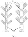
FIG.2 is a schematic structural diagram I of a microwave heating section. -
FIG.3 is a schematic structural diagram II of the microwave heating section. -
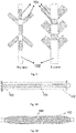
FIG. 4 is a schematic structural diagram of locations of materials in the two structures of a microwave heating section.FIG.4A is a schematic diagram of the location of the materials in the schematic structural diagram I of the microwave heating section.FIG. 4B is a schematic diagram of the location of the materials in the schematic structural diagram II of the microwave heating section. -
FIG. 5 is a schematic structural diagram of an inlet of a carrying pipeline in the schematic structural diagram I of the microwave heating section. -
FIG. 6 is a schematic diagram of mounting structures respectively corresponding to a waveguide system and a microwave absorption cavity in the two structures of the microwave heating section.FIG. 6A corresponds to the schematic structural diagram I of the microwave heating section.FIG. 6B corresponds to the schematic structural diagram II of the microwave heating section. -
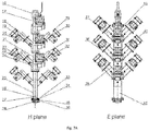
FIG. 7 is a schematic structural diagram of overall mounting of the two structures of the microwave heating section.FIG. 7A corresponds to the schematic structural diagram I of the microwave heating section.FIG. 7B corresponds to the schematic structural diagram II of the microwave heating section. - In the drawings above, 101-waveguide, 102-microwave absorption cavity, 103-carrying pipeline, 104-material, 105-wave absorbing material, and 106-quartz glass.
- 1-feeding and preheating section, 2-microwave heating section, 3-constant temperature treatment section, 4-cooling section, 5-feed tank, 6-heat preservation jacket, 7-stirring paddle, 8-screw pump, 9-electronic power supply, 10-flow meter, 11-electric heating pipe, 12-heat preservation tank, 13-cooling tank, 14-coil, 15-refrigerating compressor, 16-ball valve, 17-connecting pipe, 18-E-surface waveguide upper plate, 19-E-surface waveguide side plate, 20-E-surface waveguide lower plate, 21-microwave absorption cavity side plate I, 22-tuner, 23-waveguide flange, 24-tuner cover plate, 25-microwave absorption cavity A side plate II, 26-quartz material pipe, 27-wave absorbing material, 28-rapid connecting pipe, 29-axial fan, 30-fan cover, 31-cast aluminum excitation cavity, 32-magnetron, 33-microwave absorption cavity flange, 34-silicone rubber sealing O-shaped ring, 35-rapid connecting pipe flange, 36-tetrafluoro backing plate, 37-H-surface waveguide side plate, 38-H-surface waveguide lower plate, 39-H-surface waveguide upper plate, 40-microwave absorption cavity A side plate III, 41-dust-proof plate, 42-microwave absorption cavity A side plate IV, 43-square/circular transition pipe, 44-microwave absorption cavity B side plate I, 45-waveguide feed port quartz glass, 46-sealing flange, 47-microwave absorption cavity B side plate II, 48-E-surface waveguide upper plate, 49-E-surface waveguide B side plate, 50-E-surface waveguide lower plate, 51-waveguide-microwave absorption cavity fixing flange, 52-special flange fixing screw, 53-silicone rubber backing plate, 54-quartz glass frame plate, 55-H-surface waveguide B upper plate, 56-H-surface waveguide B lower plate, 57-H-surface waveguide B side plate, 58-microwave absorption cavity B side plate III, 59-microwave absorption cavity B side plate IV.
- In order to make the purposes, technical solutions, and advantages of the present invention clearer, the examples of the present invention will be further described in details below in combination with the drawings.
- The present example provides a microwave treatment device for a continuous liquid state material. With reference to
FIG. 1 , the microwave treatment device for a continuous liquid state material provided by the present example may be applied to microwave treatment of fluid materials. - In
FIG. 1, 1 indicates a feeding and preheating section, 2 indicates a microwave heating section, 3 indicates a constant temperature treatment section, 4 indicates a cooling section, 5 indicates a feed tank, 6 indicates a heat preservation jacket, 7 indicates a stirring paddle, 8 indicates a screw pump, 9 indicates an electronic power supply, 10 indicates a flow meter, 11 indicates an electric heating pipe, 12 indicates a heat preservation tank, 13 indicates a cooling tank, 14 indicates a coil, and 15 indicates a refrigerating compressor. - The feeding and preheating section 1 includes a feed tank 5. A material is conveyed between the feed tank 5 and the microwave heating section 2 by means of a screw pump 8. Meanwhile, a
flow meter 10 is provided in front of the microwave heating section 2 and is used to accurately control a flow rate of the liquid state material entering the microwave heating section 2. The feed tank 5 is designed as a jacket structure. That is, the feed tank 5 is placed in a heat preservation jacket 6, and the heat preservation jacket 6 is filled with hot water having a predetermined temperature for heating the liquid state material in the feed tank 5 to a predetermined temperature. The liquid state material is uniformly stirred to enable various parts thereof to have a same initial temperature while improving a heating speed and a uniformity. - The microwave heating section 2 includes a microwave generation system, a waveguide system as well as a tuner, and a microwave absorption cavity.
- The microwave generation system consists of a
magnetron 32, a cooling device, and a castaluminum excitation cavity 31. The type of themagnetron 32 is selected according to actual needs. One end of the magnetron is connected to the castaluminum excitation cavity 31, and the other end is connected to the cooling device. The cooling device includes an air-cooling and/or water-cooling device. The air-cooling device consists of anaxial fan 29 and afan cover 30 for heating dissipation of themagnetron 32 during use, so as to enable the microwave generation system to maintain at a normal work state. A dust-proof plate 41 is provided at a joint between the castaluminum excitation cavity 31 and the waveguide system, can be used for preventing foreign matters such as dust from entering the castaluminum excitation cavity 31, and plays a role in guiding air and a certain heat dissipation effect. The water-cooling device includes a water-cooling container and a circulating water pipeline. In the present example and the following examples, the air-cooling device is used as an example for description, and therefore, the water-cooling device will not be described in detail here. - Considering that a single microwave mode can improve energy stability, in order to effectively reduce electromagnetic wave modes inside the
microwave absorption cavity 102, length and width sizes of a bottom surface of the microwave absorption cavity 102 (i.e., a surface perpendicular to a material transmission direction) are designed to be the same as cavity cross-sectional length and width sizes of the usedrectangular waveguide 101. Therefore, in the present example, themicrowave absorption cavity 102 with a rectangular cavity is taken as an example for description, and the length and width sizes of the bottom surface of the microwave absorption cavity 102 (i.e., the surface perpendicular to the material transmission direction) are the same as the cavity cross-sectional length and width sizes of the usedrectangular waveguide 101. - (It should be noted that the
microwave absorption cavity 102 is also designed to be other cavities having other shapes according to actual requirements, which is not defined in the present invention.) - The waveguide system consists of a plurality of
rectangular waveguides 101 arranged in a staggered manner. A microwave feed port is provided on an outer wall of themicrowave absorption cavity 102. For convenience of description, adjacent wall surfaces among four wall surfaces of themicrowave absorption cavity 102 are respectively marked as an E surface and an H surface. That is, themicrowave absorption cavity 102 has two E surfaces and two H surfaces. - Corresponding pairs of microwave feed ports are provided on the two E surfaces at certain distances, corresponding pairs of microwave feed ports are also provided on the two H surfaces at certain distances, and a pair of microwave feed ports on the E surface is just located at an intermediate position of the microwave feed port on the H surface in a Z direction. The microwave feed ports on the E surface and the H surface have a 90-degree rotation relationship. As shown in
FIG. 2 andFIG. 3 , eachwaveguide 101 is connected to themicrowave absorption cavity 102 via the corresponding microwave feed port, and eachwaveguide 101 is connected to themicrowave absorption cavity 102 by external laser welding to ensure that inner walls of themicrowave absorption cavity 102 and thewaveguide 101 are smooth, to provide a guarantee for the uniform distribution of electromagnetic waves, to avoid excessive reflection of the electromagnetic waves, and to prevent the damage to the microwave generation system. - (It should be noted that the aforementioned arrangement mode of the microwave feed ports is not unique. In actual applications, various factors can be taken into consideration to determine the arrangement mode of the microwave feed ports according to actual requirements, such as a spiral-up arrangement mode.)
- The aforementioned arrangement mode of the microwave feed ports enables the microwave energy to be continuously transmitted to the liquid state material, thereby reducing heating cold points in the
microwave absorption cavity 102, and improving the liquid heating efficiency. Meanwhile, eachrectangular waveguide 101 is connected to the feed port on the wall surface of themicrowave absorption cavity 102 at a predetermined angle less than 90° and greater than 15°, which can effectively prevent the electromagnetic waves from being reflected back to the waveguide cavity or entering an opposite waveguide after being output, and can greatly improve the operation safety. - Each
waveguide 101 above is provided with thetuner 22, and a reflection coefficient during microwave transmission approaches 0 by adjusting an orientation and an insertion depth of the tuner. - The reflection

- The
tuner 22 may adopt a single-stub tuner. During the debugging of the continuous microwave treatment device, a network analyzer is used to measure an S11 parameter. By adjusting an orientation and insertion depth of thetuner 22 in the waveguide, S11<-10dB, and a voltage standing wave ratio approaches 1, so that microwave reflection is minimized, an microwave energy is promoted to be gathered in the microwave absorption cavity, the possibility of reflected wave penetrating the magnetron is further reduced, the magnetron is protected, the service life of the device is prolonged, the guarantee is provided for the normal and safe operation of the device, the energy utilization efficiency of the microwaves is improved, and the number of the cold points in the microwave heating section is reduced. - The S11 parameter=20 Ig (reflection coefficient), and


- In actual applications, a size of the
aforementioned tuner 22 ranges from 10-30 mm, and an insertion depth ranges from 10-60 mm. The ranges of adjustable front-back and the insertion depths of thetuner 22 are both at a quarter wavelength or above. Thetuner 22 may be made of metal materials such as stainless steel. - In actual applications, a quartz glass tube is added at an outlet of the microwave heating section 2 to observe a flow state of the fluid materials and to facilitate the control on the parameters. Meanwhile, a receiving valve is mounted at the outlet of the microwave heating section 2. A flow direction of the materials can be changed by changing the connection condition of the receiving valve so as to implement flexible material taking.
- The constant temperature treatment section 3 consists of a
heat preservation tank 12, an electric heating device, and acoil 14. Theheat preservation tank 12 is of a double-layer structure, which plays a better heat preservation role, and avoids safety hazards caused by excessive temperature. Thecoil 14 is mounted inside theheat preservation tank 12 to ensure sufficient liquid constant temperature treatment time while increasing a heat exchange area of the liquid, so that the liquid meets required sterilization requirements. The electric heating device is a stainless-steelelectric heating pipe 11, a power and a number are selected according to actual situations. A drain valve is mounted at a bottom of theheat preservation tank 12 to facilitate liquid drainage and liquid replacement. A top cover is provided at an upper portion of theheat preservation tank 12. An air outlet hole is provided on the top cover, and is mainly used to prevent the safety problem caused by excessive steam pressure in the tank. - (It should be noted that the continuous microwave treatment device may not include the constant temperature treatment section 3. For example, if the heat treatment requirements are completed in the microwave heating section 2, or the treatment process does not require the constant temperature, the constant temperature treatment section 3 may not be included.)
- The cooling and receiving section 4 consists of a
cooling tank 13, a refrigeratingcompressor 15, and acoil 14. Thecoil 14 is mounted inside thecooling tank 13 to ensure sufficient liquid cooling time while increasing the heat exchange area of the liquid. Rapid cooling also helps certain processing processes (for example, during the liquid state material sterilization process, the rapid cooling helps to kill residual microorganisms in the liquid, so that the liquid further meets sterilization requirements). The refrigeratingcompressor 15 is selected according to a flow rate of a cooling fluid, and a drain valve is mounted at a bottom of thecooling tank 13. The top cover is provided at an upper portion of thecooling tank 13. An air outlet hole is provided on the top cover, and is mainly used to balance internal and external pressures and ensure the safe operation of the device. - The microwave heating section 2 of the microwave treatment device for a continuous liquid state material provided by the prevent invention has two different structures. For convenience of description, the two structures are respectively denoted as structure I and structure II, and are introduced respectively in Example 2 and Example 3 below.
- In the present example, a carrying pipeline is further provided inside the microwave absorption cavity, and materials are circulated through inside the carrying pipeline. The details are described below.
- Referring to
FIG. 4A and FIG. 4B, FIG. 4A is a schematic diagram of the location of the material corresponding to the structure I. It can be seen fromFIG. 4A that the carryingpipeline 103 is further provided inside themicrowave absorption cavity 102 of the microwave heating section 2 in the structure I. The materials are circulated through inside the carryingpipeline 103. The carryingpipeline 103 is made of a material having good microwave permeability and a certain carrying capacity. The material having good microwave permeability includes quartz, polytetrafluoroethylene, polypropylene, high-temperature resistant glass, and the like. - If the microwave treatment device for a continuous liquid state material is used for liquid state material sterilization, in order to meet a heating rate required by liquid sterilization, for example, the liquid sterilization which requires that the temperature of the liquid state material needs to rise by N° within a period of time, the solution of the structure I is as follows.
- For structure I: referring to
FIG. 5 , a wave absorbing material is provided outside an inlet of the carryingpipeline 103, and the wave absorbing material is used to rapidly heat the materials when entering the carryingpipeline 103 to meet set heating rate requirements. - There are various implementation solutions for providing the wave absorbing material outside the inlet of the carrying
pipeline 103. One of the implementation solutions is adding the wave absorbing material directly outside a section at the inlet of the carryingpipeline 103, which can be implemented by changing a wall thickness of the section at the inlet of the carryingpipeline 103 to add the wave absorbing material. For example, as shown inFIG. 5 , an outer diameter d1 or an inner diameter d2 of the carryingpipeline 103 may be changed. In the present example, a constrained diameter design solution with d1 kept unchanged is adopted. Another implementation mode is implemented by changing a material of a section at the inlet of the carryingpipeline 103. For example, if the carryingpipeline 103 adopts a quartz pipeline, then when manufacturing the section at the inlet of the carryingpipeline 103, the wave absorbing material is added to the quartz to obtain a material having a wave absorbing function, and the material is used to manufacture the section at the inlet of the carryingpipeline 103. - In the constrained diameter design solution, a length of the constrained diameter may be adjusted according to the distance between the inlet of the carrying
pipeline 103 and a first microwave feed port. For example, if the distance from the microwave feed port is long, the length of the constrained diameter portion may be increased accordingly, and the length of the constrained diameter should be adjusted according to actual situations and requirements. If the material needs to be heated rapidly, then the length of the constrained diameter should be appropriately increased, that is, the added wave absorbing materials are increased, so that the heat is more concentrated and is rapidly transmitted to the material. The constrained design solution facilitates the connection between the carryingpipeline 103 and an external pipeline, makes the mounting and disassembly processes easy, helps the sealing of the carryingpipeline 103, and effectively prevents microwave from leaking. - In the present example, a carrying pipeline is not additionally provided inside the microwave absorption cavity, and the materials are directly circulated through inside the microwave absorption cavity. The details are described below.
- Referring to
FIG. 4A and FIG. 4B, FIG. 4B is a schematic diagram of the location of materials corresponding to the structure II. It can be seen fromFIG. 4B that the materials are directly circulated through inside themicrowave absorption cavity 102. Therefore, the microwave feed port on the wall surface of themicrowave absorption cavity 102 of the microwave heating section 2 is sealed by using the sealing material. The sealing material has good microwave permeability and a certain carrying capacity, which includes quartz, polytetrafluoroethylene, polypropylene, high-temperature resistant glass, and the like, and may be used by stacking one or more materials. - If the microwave treatment device for a continuous liquid state material of this structure is used for liquid state material sterilization, in order to meet a heating rate required by liquid sterilization, for example, the liquid sterilization requires that the temperature of the liquid state material needs to rise by N° within a period of time, the solution of the structure II is as follows.
- For the structure II, as shown in
FIG. 3 , since the materials are directly circulated through inside themicrowave absorption cavity 102, the heating rate requirement may be met by adjusting an inclination direction of waveguides on E surfaces and/or H surfaces with respect to the wall surface of themicrowave absorption cavity 102. Specifically, the waveguides on the two E surfaces may be adjusted to be toward an intermediate position of themicrowave absorption cavity 102, and the inclination direction of the waveguides on the two H surfaces is kept unchanged, so as to, as shown inFIG. 3 , implement centralized output of an microwave energy conveyed into themicrowave absorption cavity 102 to an intermediate part thereof, so that the materials therein can be rapidly heated to meet the heating rate required by liquid sterilization. - It should be noted that the inclination direction of each waveguide in the waveguide system can be specifically adjusted according to actual requirements. For example, the inclination direction of any waveguide may be adjusted to be toward one direction, rather than limited to the waveguide on the E surface or the H surface.
- When the microwave treatment device for a continuous liquid state material provided in Examples 1-3 of the present invention performs treatment on the fluid materials, and when the liquid materials flow, from bottom to top, through the
microwave absorption cavity 102 or the carryingpipeline 103 therein, a lower end of the microwave absorption cavity is connected and fixed by means of aflange 33. Atetrafluoro backing plate 36 and a silicone rubber O-shapedring 34 are added between a cavity of themicrowave absorption cavity 102 or an inlet end of the carryingpipeline 103 therein and theflange 33 to ensure the tightness, and prevent microwave leakage. Meanwhile, themicrowave absorption cavity 102 or the carryingpipeline 103 therein is connected to an external pipeline using a rapid connectingpipe 28, and is fixed by a rapid connectingpipe flange 35. In food industry, the external pipeline may use stainless steel 316 and 316 L. - In the present invention, the thermal effect of the microwave is mainly applied, the materials are rapidly heated in the cavity of the microwave transmission system and reaches the required treatment temperature by means of the special design in the microwave heating section. In conjunction with the constant temperature and cooling sections, the temperature and time during treatment are further ensured, and the continuous microwave heating process of the liquid state material is implemented.
- The above descriptions are only preferred examples of the present invention, and are not used to define the present invention. Any modification, equivalent replacement, improvement, and the like made within the spirit and principle of the present invention all should be included in the scope of protection of the present invention.
Claims (15)
- A microwave treatment device for a continuous liquid state material, characterized by comprising: a feeding and preheating section, a microwave heating section, and a cooling and receiving section;
wherein the microwave heating section comprises a microwave generation system, a waveguide system as well as a tuner, and a microwave absorption cavity; the waveguide system comprises at least two waveguides, each waveguide is mounted at a microwave feed port provided on an outer wall of the microwave absorption cavity according to a predetermined angle, and the predetermined angle is greater than or equal to 15° and less than 90°. - The microwave treatment device for a continuous liquid state material according to claim 1, characterized in that the tuner is provided in each waveguide, and a reflection coefficient during microwave transmission approaches 0 and a voltage standing wave ratio approaches 1 by adjusting an orientation and an insertion depth of the turner.
- The microwave treatment device for a continuous liquid state material according to claim 1 or 2, characterized in that the predetermined angle ranges from 30° to 60°.
- The microwave treatment device for a continuous liquid state material according to any one of claims 1 to 3, characterized in that inclination directions of the waveguides with respect to a wall surface of the microwave absorption cavity are consistent, partially consistent, or different.
- The microwave treatment device for a continuous liquid state material according to claim 4, characterized in that a carrying pipeline is further provided inside the microwave absorption cavity.
- The microwave treatment device for a continuous liquid state material according to claim 5, characterized in that a rapid heating device is provided at an inlet of the carrying pipeline, and the rapid heating device is configured to rapidly heat the material when entering the carrying pipeline to meet set heating rate requirements.
- The microwave treatment device for a continuous liquid state material according to claim 6, characterized in that a wave absorbing material is provided outside the inlet of the carrying pipeline, and the wave absorbing material is configured to rapidly heat the material when entering the carrying pipeline to meet set heating rate requirements.
- The microwave treatment device for a continuous liquid state material according to claim 7, characterized in that an outer diameter of the inlet of the carrying pipeline is the same as an outer diameter of a pipeline part of the carrying pipeline not provided with the wave absorbing material.
- The microwave treatment device for a continuous liquid state material according to claim 4, characterized in that a sealing material is mounted at a microwave feed port, the sealing material is located between each waveguide and the micro absorption cavity, and the sealing material has a carrying capacity and a microwave permeability, and is a low-loss or non-loss insulator.
- The microwave treatment device for a continuous liquid state material according to claim 9, characterized in that the inclination direction of each waveguide with respect to the wall surface of the microwave absorption cavity faces a middle part of the microwave absorption cavity.
- The microwave treatment device for a continuous liquid state material according to any one of claims 1-10, characterized in that the microwave absorption cavity is a rectangular cavity; a cavity cross-section of each waveguide has a same shape and size as that of a bottom surface of the microwave absorption cavity, and the bottom surface of the microwave absorption cavity is a surface perpendicular to a material transmission direction.
- The microwave treatment device for a continuous liquid state material according to claim 11, characterized in that the microwave generation system comprises a magnetron, a cooling device, and a cast aluminum excitation cavity; one end of the magnetron is connected to the cast aluminum excitation cavity, and the other end is connected to the cooling device; the cooling device comprises an air-cooling and/or water-cooling device, wherein the air-cooling device comprises an axial fan and a fan cover for heat dissipation of the magnetron; a dust-proof plate for preventing foreign matters from entering the cast aluminum excitation cavity is provided at a joint between the cast aluminum excitation cavity and the waveguide system; and the water-cooling device comprises a water-cooling container and a circulating water pipeline.
- The microwave treatment device for a continuous liquid state material according to any one of claims 1 to 12, characterized in that the feeding and preheating section comprises a feed tank; the material is conveyed between the feed tank and the microwave heating section by means of a screw pump; and meanwhile, a flow meter is provided in front of the microwave heating section and is configured to accurately control a flow rate of the liquid state material entering the microwave heating section; the feed tank is designed as a jacket structure that is filled with hot water having a predetermined temperature for heating the liquid state material in the feed tank to a predetermined temperature; and the liquid state material is uniformly stirred to enable various parts thereof to have a same initial temperature while improving a heating speed and a uniformity.
- The microwave treatment device for a continuous liquid state material according to any one of claims 1 to 13, characterized by further comprising a constant temperature treatment section connected between the microwave heating section and the cooling and receiving section, wherein the constant temperature treatment section comprises a heat preservation tank, a heating device, and a coil; the heat preservation tank is of a double-layer structure; the coil is mounted inside the heat preservation tank for ensuring a sufficient constant treatment time of the liquid state material while increasing a heat exchange area of the liquid state material; a drain valve is mounted at a bottom of the heat preservation tank for liquid drainage and liquid replacement; and an air outlet hole is provided on a top cover at an upper portion of the heat preservation tank for balancing internal and external air pressures.
- The microwave treatment device for a continuous liquid state material according to any one of claims 1 to 14, characterized in that the cooling and receiving section comprises a cooling tank, a refrigerating compressor, and a coil; the coil is mounted inside the cooling tank for ensuring a sufficient liquid cooling time while increasing the heat exchange area of the liquid state material; the drain valve is mounted at a bottom of the cooling tank; and an air outlet hole is provided on a top cover at an upper portion of the cooling tank for balancing internal and external air pressures.
Applications Claiming Priority (2)
| Application Number | Priority Date | Filing Date | Title |
|---|---|---|---|
| CN201920107215.1U CN210183589U (en) | 2019-01-22 | 2019-01-22 | Continuous liquid material microwave processing equipment |
| PCT/CN2019/088566 WO2020151146A1 (en) | 2019-01-22 | 2019-05-27 | Microwave treatment device for continuous liquid state material |
Publications (2)
| Publication Number | Publication Date |
|---|---|
| EP3917283A1 true EP3917283A1 (en) | 2021-12-01 |
| EP3917283A4 EP3917283A4 (en) | 2022-10-19 |
Family
ID=69828871
Family Applications (1)
| Application Number | Title | Priority Date | Filing Date |
|---|---|---|---|
| EP19911042.0A Pending EP3917283A4 (en) | 2019-01-22 | 2019-05-27 | MICROWAVE TREATMENT DEVICE FOR MATERIAL IN CONTINUOUS LIQUID STATE |
Country Status (4)
| Country | Link |
|---|---|
| US (1) | US11805578B2 (en) |
| EP (1) | EP3917283A4 (en) |
| CN (1) | CN210183589U (en) |
| WO (1) | WO2020151146A1 (en) |
Families Citing this family (7)
| Publication number | Priority date | Publication date | Assignee | Title |
|---|---|---|---|---|
| CN115518595A (en) * | 2021-06-26 | 2022-12-27 | 李伟南 | Box-type pipeline microwave radiation device |
| CN113685160A (en) * | 2021-08-31 | 2021-11-23 | 西南石油大学 | A device and method for removing water phase damage by microwave heat shock in oil and gas wells |
| CN114486622B (en) * | 2022-01-19 | 2023-10-20 | 山东交通学院 | An experimental device and method for measuring the density of liquids at different temperatures in real time |
| CN114574819A (en) * | 2022-04-02 | 2022-06-03 | 华映科技(集团)股份有限公司 | Evaporation plating machine using microwave as heating source |
| CN114800990A (en) * | 2022-04-27 | 2022-07-29 | 青岛慧智兰智能科技有限公司 | Disposable glove microwave heating equipment |
| JP7786338B2 (en) * | 2022-11-08 | 2025-12-16 | トヨタ自動車株式会社 | Microwave irradiation device and method for producing metal nanoparticles |
| EP4744494A1 (en) * | 2024-11-15 | 2026-05-20 | Pavan S.p.A. | DEVICE FOR PASTEURIZING FOOD |
Family Cites Families (10)
| Publication number | Priority date | Publication date | Assignee | Title |
|---|---|---|---|---|
| AU4487789A (en) * | 1988-10-25 | 1990-05-14 | Industrial Microwave Applications Pty. Limited | Microwave pipe warmer |
| DE10260743B4 (en) * | 2002-12-23 | 2008-05-15 | Outokumpu Oyj | Process and plant for the thermal treatment of granular solids in a fluidized bed |
| CN1849846A (en) * | 2003-09-08 | 2006-10-18 | 华盛顿州立大学研究基金会 | Apparatus and method for heating objects with microwaves |
| CN201252654Y (en) * | 2008-04-15 | 2009-06-03 | 上海鸿泽企业发展有限公司 | Spiral conveying and agitating type microwave heating device |
| JP5769287B2 (en) * | 2009-12-05 | 2015-08-26 | 国立研究開発法人産業技術総合研究所 | Method for producing metal fine particles |
| CN201860474U (en) * | 2010-09-30 | 2011-06-08 | 中国农业机械化科学研究院 | Microwave heating energy-feedback antenna and microwave vacuum drying device equipped with the same |
| FR2974701B1 (en) * | 2011-04-27 | 2014-03-21 | Sairem Soc Pour L Applic Ind De La Rech En Electronique Et Micro Ondes | PRODUCTION PLANT FOR MICROWAVE PLASMA |
| CN204275959U (en) * | 2014-12-10 | 2015-04-22 | 吉林工业职业技术学院 | A kind of macromolecule chemical industry reaction microwave rabble furnace |
| CN106747272B (en) * | 2016-11-18 | 2019-08-23 | 侯梦斌 | A kind of microwave energy ceramic firing equipment and technology with heat exchange |
| US10790118B2 (en) * | 2017-03-16 | 2020-09-29 | Mks Instruments, Inc. | Microwave applicator with solid-state generator power source |
-
2019
- 2019-01-22 CN CN201920107215.1U patent/CN210183589U/en active Active
- 2019-05-27 EP EP19911042.0A patent/EP3917283A4/en active Pending
- 2019-05-27 WO PCT/CN2019/088566 patent/WO2020151146A1/en not_active Ceased
-
2020
- 2020-08-10 US US16/988,787 patent/US11805578B2/en active Active
Also Published As
| Publication number | Publication date |
|---|---|
| WO2020151146A1 (en) | 2020-07-30 |
| EP3917283A4 (en) | 2022-10-19 |
| US11805578B2 (en) | 2023-10-31 |
| CN210183589U (en) | 2020-03-24 |
| US20200374994A1 (en) | 2020-11-26 |
Similar Documents
| Publication | Publication Date | Title |
|---|---|---|
| US11805578B2 (en) | Microwave processing equipment for continuous flow liquids | |
| CN109701475B (en) | A microwave-ultrasonic coupling processing device, equipment and application for liquid materials | |
| CN210165070U (en) | A constant temperature pipeline type chemical raw material conveying device | |
| CN105813252B (en) | Using the industrial microwave heating equipment of helical antenna radial radiation power | |
| CN101530676B (en) | A large-capacity layered radiation microwave extraction device | |
| CN101518722A (en) | Microwave chemical reaction apparatus using dielectric radiator | |
| CN109587859B (en) | A waveguide type microwave heating equipment for liquid materials | |
| US8138458B2 (en) | Microwave chemical reaction device | |
| CN209982770U (en) | A continuous microwave-ultrasonic coupling processing equipment for liquid materials | |
| CN109729611B (en) | Microwave cavity suitable for liquid material | |
| CN111211393B (en) | Water cooling plant for coupler | |
| CN109688653B (en) | Microwave pipeline type heating rapid heating device | |
| CN208589548U (en) | A kind of circular waveguide leaky wave slot antenna based on TM01 mould | |
| CN110050935B (en) | A continuous microwave UHT equipment suitable for liquid materials | |
| CN107910306A (en) | A kind of water-cooling type radiator and cooling system | |
| CN208584705U (en) | A kind of gelatin formation system | |
| CN218554061U (en) | T-shaped single-mode microwave chemical reaction unit | |
| CN213481077U (en) | Circulation type heat exchanger | |
| AU6570094A (en) | Process and plant for the manufacture of solid castings froman essentially liquid reactive medium, and oven for heating an essentially liquid medium | |
| CN109618442B (en) | A microwave-ultrasonic coupling cavity suitable for liquid materials | |
| CN212215412U (en) | Production equipment for graphene conductive paste for battery | |
| CN211837755U (en) | Paint mixing of colors agitated vessel | |
| CN211035898U (en) | Temperature-controllable food fermentation device | |
| CN211329143U (en) | Efficient corrosion inhibitor preparation equipment | |
| CN118807654B (en) | Microwave reaction device |
Legal Events
| Date | Code | Title | Description |
|---|---|---|---|
| STAA | Information on the status of an ep patent application or granted ep patent |
Free format text: STATUS: THE INTERNATIONAL PUBLICATION HAS BEEN MADE |
|
| PUAI | Public reference made under article 153(3) epc to a published international application that has entered the european phase |
Free format text: ORIGINAL CODE: 0009012 |
|
| STAA | Information on the status of an ep patent application or granted ep patent |
Free format text: STATUS: REQUEST FOR EXAMINATION WAS MADE |
|
| 17P | Request for examination filed |
Effective date: 20210820 |
|
| AK | Designated contracting states |
Kind code of ref document: A1 Designated state(s): AL AT BE BG CH CY CZ DE DK EE ES FI FR GB GR HR HU IE IS IT LI LT LU LV MC MK MT NL NO PL PT RO RS SE SI SK SM TR |
|
| DAV | Request for validation of the european patent (deleted) | ||
| DAX | Request for extension of the european patent (deleted) | ||
| REG | Reference to a national code |
Ref country code: DE Ref legal event code: R079 Free format text: PREVIOUS MAIN CLASS: H05B0006640000 Ipc: H05B0006700000 |
|
| STAA | Information on the status of an ep patent application or granted ep patent |
Free format text: STATUS: EXAMINATION IS IN PROGRESS |
|
| A4 | Supplementary search report drawn up and despatched |
Effective date: 20220916 |
|
| RIC1 | Information provided on ipc code assigned before grant |
Ipc: A23L 3/01 20060101ALI20220912BHEP Ipc: H05B 6/70 20060101AFI20220912BHEP |
|
| 17Q | First examination report despatched |
Effective date: 20220928 |