EP3917242A1 - Terminal device, base station device, and communication method - Google Patents
Terminal device, base station device, and communication method Download PDFInfo
- Publication number
- EP3917242A1 EP3917242A1 EP20745816.7A EP20745816A EP3917242A1 EP 3917242 A1 EP3917242 A1 EP 3917242A1 EP 20745816 A EP20745816 A EP 20745816A EP 3917242 A1 EP3917242 A1 EP 3917242A1
- Authority
- EP
- European Patent Office
- Prior art keywords
- resource
- configuration
- higher layer
- terminal apparatus
- downlink
- Prior art date
- Legal status (The legal status is an assumption and is not a legal conclusion. Google has not performed a legal analysis and makes no representation as to the accuracy of the status listed.)
- Granted
Links
Images



Classifications
-
- H—ELECTRICITY
- H04—ELECTRIC COMMUNICATION TECHNIQUE
- H04W—WIRELESS COMMUNICATION NETWORKS
- H04W72/00—Local resource management
- H04W72/04—Wireless resource allocation
- H04W72/044—Wireless resource allocation based on the type of the allocated resource
- H04W72/0453—Resources in frequency domain, e.g. a carrier in FDMA
-
- H—ELECTRICITY
- H04—ELECTRIC COMMUNICATION TECHNIQUE
- H04W—WIRELESS COMMUNICATION NETWORKS
- H04W76/00—Connection management
- H04W76/20—Manipulation of established connections
- H04W76/27—Transitions between radio resource control [RRC] states
-
- H—ELECTRICITY
- H04—ELECTRIC COMMUNICATION TECHNIQUE
- H04L—TRANSMISSION OF DIGITAL INFORMATION, e.g. TELEGRAPHIC COMMUNICATION
- H04L5/00—Arrangements affording multiple use of the transmission path
- H04L5/003—Arrangements for allocating sub-channels of the transmission path
- H04L5/0044—Allocation of payload; Allocation of data channels, e.g. PDSCH or PUSCH
-
- H—ELECTRICITY
- H04—ELECTRIC COMMUNICATION TECHNIQUE
- H04L—TRANSMISSION OF DIGITAL INFORMATION, e.g. TELEGRAPHIC COMMUNICATION
- H04L5/00—Arrangements affording multiple use of the transmission path
- H04L5/0091—Signalling for the administration of the divided path, e.g. signalling of configuration information
- H04L5/0096—Indication of changes in allocation
- H04L5/0098—Signalling of the activation or deactivation of component carriers, subcarriers or frequency bands
Definitions
- the present invention relates to a terminal apparatus, a base station apparatus, and a communication method.
- the present application claims priority based on Japanese Patent Application No. 2019-10206 filed on January 24, 2019 , the content of which is incorporated herein by reference.
- LTE Long Term Evolution
- EUTRA Evolved Universal Terrestrial Radio Access
- 3GPP 3rd Generation Partnership Project
- LTE Long Term Evolution
- eNodeB a base station apparatus
- UE User Equipment
- LTE is a cellular communication system in which areas covered by a plurality of base station apparatuses are arranged in a cell-like configuration.
- a single base station apparatus may also manage multiple serving cells.
- NPL 1 New Radio or NR
- IMT International Mobile Telecommunication
- ITU International Telecommunication Union
- eMBB enhanced Mobile BroadBand
- mMTC massive Machine Type Communication
- URLLC Ultra Reliable and Low Latency Communication
- NPL 1 " New SID proposal: Study on New Radio Access Technology", RP-160671, NTT docomo, 3GPP TSG RAN Meeting # 71, Goteborg, Sweden, March 7th-10th, 2016 .
- the present invention provides a terminal apparatus that performs communication efficiently, a communication method for the terminal apparatus, a base station apparatus that performs communication efficiently, and a communication method for the base station apparatus.
- the first aspect of the present invention is to provide a terminal apparatus comprising: a higher layer processing unit configured to receive a radio resource control parameter specific to the terminal apparatus and related to a transmission bandwidth configuration; and a reception unit configured to receive a downlink shared channel in an active downlink bandwidth part of a carrier corresponding to the transmission bandwidth configuration.
- the transmission bandwidth configuration is given at least based on an initial downlink bandwidth part.
- the second aspect of the present invention is to provide a base station apparatus comprising: a higher layer processing unit configured to transmit a radio resource control parameter specific to the terminal apparatus and related to a transmission bandwidth configuration; and a transmission unit configured to transmit a downlink shared channel in an active downlink bandwidth part of a carrier corresponding to the transmission bandwidth configuration.
- the transmission bandwidth configuration is given at least based on an initial downlink bandwidth part.
- the third aspect of the present invention is to provide a communication method for a terminal apparatus having a computer.
- the communication method is performed by the computer and comprises: performing a higher layer processing process to receive a radio resource control parameter specific to the terminal apparatus and related to a transmission bandwidth configuration; and performing a reception process to receive a downlink shared channel in an active downlink bandwidth part of a carrier corresponding to the transmission bandwidth configuration.
- the transmission bandwidth configuration is given at least based on an initial downlink bandwidth part.
- the fourth aspect of the present invention is to provide a communication method for a base station apparatus having a computer.
- the communication method is performed by the computer and comprises: performing a higher layer processing process to transmit a radio resource control parameter specific to the terminal apparatus and related to a transmission bandwidth configuration; and performing a transmission process to transmit a downlink shared channel in an active downlink bandwidth part of a carrier corresponding to the transmission bandwidth configuration.
- the transmission bandwidth configuration is given at least based on an initial downlink bandwidth part.
- the terminal apparatus can perform communication efficiently.
- the base station apparatus can perform communication efficiently.
- a and/or B may be a term that includes “A”, “B”, or "A and B”.
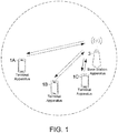
- FIG. 1 is a conceptual diagram of a wireless communication system according to one aspect of the present embodiment.
- the wireless communication system includes terminal apparatuses 1A to 1C and a base station apparatus 3 (BS #3: Base Station #3).
- BS #3 Base Station #3
- the terminal apparatuses 1A to 1C are refer to as a terminal apparatus 1 (UE #1: User Equipment #1).
- the base station apparatus 3 may be configured to include one or both of an MCG (Master Cell Group) and an SCG (Secondary Cell Group).
- the MCG is a group of serving cells that include at least a PCell (Primary Cell).
- the SCG is a group of serving cells that include at least a PSCell (Primary Secondary Cell).
- the PCell may be a serving cell given based on an initial connection.
- the PCell may also be a serving cell where an initial connection is performed.
- the MCG may also include one or more SCells (Secondary cells).
- the SCG may also include one or more SCells.
- the PCell is also referred to as a primary cell.
- the PScell is also referred to as a primary secondary cell.
- the SCell is also referred to as a secondary cell.
- the MCG may also include serving cells in an EUTRA.
- the SCG may also include serving cells in a next generation standard (New Radio (NR)).
- NR New Radio
- At least OFDM Orthogonal Frequency Division Multiplexing
- An OFDM symbol is a unit of an OFDM time domain.
- An OFDM symbol includes at least one or more subcarriers.
- An OFDM symbol may also be converted into a time-continuous signal in generation of a baseband signal.
- CP-OFDM Cyclic Prefix Orthogonal Frequency Division Multiplexing
- DFT-s-OFDM Discrete Fourier Transform -Spread - Orthogonal Frequency Division Multiplexing
- the DFT-s-OFDM is given by applying transform precoding to the CP-OFDM.
- the OFDM symbol may also be a term including a CP attached to the OFDM symbol.
- a certain OFDM symbol may be configured to include the certain OFDM symbol and a CP attached to the certain OFDM symbol.
- a subcarrier spacing configuration ⁇ may be configured to be any one of 0, 1, 2, 3, 4, and/or 5.
- the subcarrier spacing configuration ⁇ may be given by a higher layer parameter.
- a time unit T c may be used to represent the length of a time domain.
- ⁇ f max may be the maximum value of the subcarrier spacing supported in the wireless communication system according to one aspect of the present embodiment.
- ⁇ f ref may be 15 kHz.
- N f,ref may be 2048.
- the constant ⁇ may be a value indicating a relationship between a reference subcarrier spacing and T c .
- the constant ⁇ may be used for a length of a subframe.
- the number of slots included in the subframe may be given at least based on the constant ⁇ .
- ⁇ f ref is the reference subcarrier spacing
- N f,ref is a value corresponding to the reference subcarrier spacing.
- the transmission of a signal on a downlink and/or the transmission of a signal on an uplink may be organized into 10ms frames.
- a frame includes 10 subframes.
- the length of a subframe is 1 ms.
- the length of a frame may be given independently of the subcarrier spacing ⁇ f. In other words, the length of a frame may be given independently of ⁇ .
- the length of a subframe may be given independently of the subcarrier spacing ⁇ f. In other words, the length of a subframe may be given independently of ⁇ .
- a slot number n ⁇ s may be given by an integer value in ascending order in a range from 0 to N subframe, ⁇ slot ⁇ 1 within a subframe.
- the number and indexes of slots included in a frame may be given.
- a slot number n ⁇ s may be given by an integer value in ascending order in a range from 0 to N frame, ⁇ slot ⁇ 1 within a frame.
- N slot symb consecutive OFDM symbols may be included in one slot.
- N slot symb may be given at least based on some or all of CP (Cyclic Prefix) configurations.
- the CP configuration may be given at least based on a higher layer parameter.
- the CP configuration may be given at least based on dedicated RRC signaling.
- the slot number is also referred to as a slot index.
- FIG. 2 is an example showing a relationship among N slot symb , a subcarrier spacing configuration ⁇ , and a CP configuration according to one aspect of the present embodiment.
- An antenna port is defined in such a manner that a channel on which a symbol is transmitted on one antenna port can be inferred from a channel on which another symbol is transmitted on the same antenna port.
- the two antenna ports are referred to as being QCL (Quasi Co-Located).
- the large scale property may include at least a long term property of a channel.
- the large scale property may include at least some or all of delay spread, Doppler spread, Doppler shift, average gain, average delay, and spatial Rx parameters.
- the fact that a first antenna port and a second antenna port are QCL with respect to a beam parameter may mean that a reception beam assumed by the reception side for the first antenna port may be the same as a reception beam assumed by the reception side for the second antenna port.
- the fact that a first antenna port and a second antenna port are QCL with respect to a beam parameter may mean that a transmission beam assumed by the reception side for the first antenna port may be the same as a transmission beam assumed by the reception side for the second antenna port.
- the terminal apparatus 1 may assume the two antenna ports to be QCL.
- the fact that two antenna ports are QCL may mean that the two antenna ports are assumed to be QCL.
- N size, ⁇ grid , x N RB SC subcarriers and N subframe, ⁇ symb OFDM symbols is given for a subcarrier spacing configuration and a carrier set.
- N size, ⁇ grid , x may indicate the number of resource blocks given for the subcarrier spacing configuration ⁇ .
- N size, ⁇ grid , x may also represent the bandwidth of a carrier.
- N size, ⁇ grid , x may also correspond to the value of a higher layer parameter CarrierBandwidth.
- the carrier x may indicate either a downlink carrier or an uplink carrier. In other words, x may be either "DL" or "UL".
- N RB SC may indicate the number of subcarriers included in one resource block.
- N RB SC may be 12.
- At least one resource grid may be given for each antenna port p and/or for each subcarrier spacing configuration ⁇ and/or for each transmission direction configuration.
- the transmission direction includes at least a downlink (DL) and an uplink (UL).
- DL downlink
- UL uplink
- a set of parameters including at least some or all of the antenna port p, the subcarrier spacing configuration ⁇ , and the transmission direction configuration is also referred to as a first radio parameter set.
- one resource grid may be given for each first radio parameter set.
- a resource block is a general term for a common resource block and a physical resource block.
- the index of the resource block may also be given in ascending order from a reference point.
- a resource block corresponding to a certain subcarrier spacing configuration ⁇ may be a resource block including resource elements given based on the subcarrier spacing configuration ⁇ .
- a carrier included in a serving cell is referred to as a downlink carrier (or a downlink component carrier).
- a carrier included in a serving cell is referred to as an uplink carrier (an uplink component carrier).
- the downlink component carrier and the uplink component carrier are collectively referred to as a component carrier (or a carrier).
- the type of the serving cell may be any one of a PCell, a PSCell, and a SCell.
- the PCell may be a serving cell identified at least based on a cell ID acquired from an SS/PBCH in an initial connection.
- the PCell may be at least configured with a RACH resource.
- the SCell may be a serving cell used in carrier aggregation.
- the SCell may be a serving cell given at least based on dedicated RRC signaling.
- Each element in the resource grid given for each first radio parameter set is referred to as a resource element.
- the resource element is identified at least based on a frequency domain index k sc and a time domain index l sym .
- the resource element is identified at least based on a frequency domain index k sc and a time domain index l sym .
- the resource element identified by the frequency domain index k sc and the time domain index l sym is also referred to as a resource element (k sc , l sym ).
- the frequency domain index k sc indicates any of values from 0 to N ⁇ RB N RB sc -1.
- N ⁇ RB may be the number of resource blocks given for the the subcarrier spacing configuration ⁇ .
- the frequency domain index ksc may correspond to a subcarrier index k sc .
- the time domain index l sym may correspond to an OFDM symbol index l sym .
- FIG. 3 is a schematic diagram showing an example of a resource grid in a subframe according to one aspect of the present embodiment.
- a horizontal axis is a time domain index l sym
- a vertical axis is a frequency domain index k sc .
- the frequency domain of the resource grid includes N ⁇ RB N RB SC subcarriers.
- the time domain of the resource grid may include 14 • 2 ⁇ OFDM symbols.
- One resource block includes N RB SC subcarriers.
- the time domain of the resource block may correspond to one OFDM symbol.
- the time domain of the resource block may also correspond to fourteen OFDM symbols.
- the time domain of the resource block may correspond to one or more time slots.
- the time domain of the resource block may also correspond to one subframe.
- the frequency domain of the resource grid including N ⁇ RB N RB SC subcarriers may correspond to the frequency domain of the resource grid including N ⁇ RB resource blocks.
- the terminal apparatus 1 may be indicated to perform transmission/ reception using only a subset of the resource grid.
- the subset of a resource grid is also referred to as a BWP and may be given based on at least some or all of higher layer parameters and/or DCI.
- the BWP is also referred to as a carrier bandwidth part.
- the BWP is also referred to as a BandWidth Part.
- the terminal apparatus 1 may not be indicated to perform transmission and/or reception using all sets of the resource grids.
- the terminal apparatus 1 may be indicated to perform transmission/ reception using some frequency resources within the resource grid.
- One BWP may include a plurality of resource blocks in the frequency domain.
- One BWP may include a plurality of consecutive resource blocks in the frequency domain.
- the BWP configured for a downlink carrier is also referred to as a downlink BWP.
- the BWP configured for an uplink carrier is also referred to as an uplink BWP.
- the BWP may also be a subset of a carrier frequency band.
- One or more downlink BWPs may be configured for each of serving cells.
- One or more uplink BWPs may be configured for each of serving cells.
- One downlink BWP of the one or more downlink BWPs configured for a serving cell may be configured (or activated) as an active downlink BWP.
- a downlink BWP switch is used to deactivate one active downlink BWP and activate an inactive downlink BWP other than the one active downlink BWP.
- the downlink BWP switch may be controlled by a BWP field included in downlink control information.
- the downlink BWP switch may also be controlled based on a higher layer parameter.
- DL-SCH may be received in an active downlink BWP.
- PDCCH may be monitored in an active downlink BWP.
- PDSCH may be received in an active downlink BWP.
- Some or all of a PDSCH, a PDCCH, and a CSI-RS may not be received outside of an active downlink BWP.
- DL-SCH may not be received in an inactive downlink BWP.
- PDCCH may not be monitored in an inactive downlink BWP.
- CSI for an inactive downlink BWP may not be reported.
- Two or more downlink BWPs of the one or more downlink BWPs configured for a serving cell may not be configured as active downlink BWPs. At a certain time, one downlink BWP is active.
- One uplink BWP of the one or more uplink BWPs configured for a serving cell may be configured (or activated) as an active uplink BWP.
- An uplink BWP switch is used to deactivate one active uplink BWP and activate an inactive uplink BWP other than the one active uplink BWP.
- the uplink BWP switch may be controlled by a BWP field included in downlink control information.
- the uplink BWP switch may also be controlled based on a higher layer parameter.
- UL-SCH may be transmitted in an active uplink BWP.
- PUCCH may be transmitted in an active uplink BWP.
- PRACH may be transmitted in an active uplink BWP.
- SRS may be transmitted in an active uplink BWP.
- UL-SCH is not transmitted in an inactive uplink BWP.
- PUCCH is not transmitted in an in active uplink BWP.
- PRACH is not transmitted in an inactive uplink BWP.
- SRS is not transmitted in an inactive uplink BWP.
- Two or more uplink BWPs of the one or more uplink BWPs configured for a serving cell may not be configured as active uplink BWPs. At a certain time, one uplink BWP may be active.
- the higher layer parameter is a parameter included in a higher layer signal.
- the higher layer signal may be RRC (Radio Resource Control) signaling or MAC CE (Medium Access Control Control Element).
- RRC Radio Resource Control
- MAC CE Medium Access Control Control Element
- the higher layer signal may be an RRC layer signal or may be a MAC layer signal.
- the higher layer signal may be common RRC signaling.
- the common RRC signaling may include at least some or all of the following features C1 to C3.
- the ReconfigrationWithSync information element may include information indicating a configuration commonly used in the serving cell.
- the configuration commonly used in the serving cell may include at least a PRACH configuration.
- the PRACH configuration may indicate at least one or more random access preamble indexes.
- the PRACH configuration may indicate at least a PRACH time/frequency resource.
- the common RRC signaling may include at least a common RRC parameter.
- the common RRC parameter may also be a cell-specific parameter that is commonly used in the serving cell.
- the higher layer signal may be dedicated RRC signaling.
- the dedicated RRC signaling may include at least some or all of the following features D1 to D2.
- an MIB Master Information Block
- an SIB System Information Block
- a higher layer message that is mapped to the DCCH logical channel and includes at least the ReconfigurationWithSync information element may be common RRC signaling.
- a higher layer message that is mapped to the DCCH logical channel and does not include the ReconfigurationWithSync information element may be included in the dedicated RRC signaling.
- the SIB may at least indicate a time index of an SS (Synchronization Signal) block.
- the SS block is also referred to as an SS/PBCH block.
- the SIB may include at least information related to a PRACH resource.
- the SIB may include at least information related to an initial connection configuration.
- the ReconfigrationWithSync information element may include at least information related to a PRACH resource (or a RACH resource).
- the ReconfigurationWithSync information element may include at least information related to a random access configuration.
- the dedicated RRC signaling may include at least a dedicated RRC parameter.
- the dedicated RRC parameter may be a UE-specific parameter dedicated to the terminal apparatus 1.
- the common RRC parameter and the dedicated RRC parameter are referred to as higher layer parameters.
- One physical channel may be mapped to one serving cell.
- One physical channel may be mapped to one carrier band part configured for one carrier included one a serving cell.
- An uplink physical channel may correspond to a set of resource elements that transmit information generated in a higher layer.
- the uplink physical channel may be a physical channel used in an uplink carrier.
- at least some or all of the following uplink physical channels may be used.
- the PUCCH may be used to transmit uplink control information (UCI).
- the uplink control information includes some or all of Channel State Information (CSI), a Scheduling Request (SR), and a Hybrid Automatic Repeat request ACKnowledgement (HARQ-ACK) information.
- CSI Channel State Information
- SR Scheduling Request
- HARQ-ACK Hybrid Automatic Repeat request ACKnowledgement
- the uplink control information may be multiplexed on the PUCCH.
- the multiplexed PUCCH may be transmitted.
- the uplink control information may be mapped to the PUCCH.
- the HARQ-ACK information may include at least a HARQ-ACK bit corresponding to a transport block (Transport Block (TB), Medium Access Control Protocol Data Unit (MAC PDU), Downlink-Shared Channel (DL-SCH), Uplink-Shared Channel (UL-SCH), or Physical Downlink Shared Channel (PDSCH)).
- the HARQ-ACK bit may indicate an ACK (acknowledgement) or a NACK (negative-acknowledgement) corresponding to the transport block.
- the ACK may be a value indicating that decoding of the transport block is successfully completed.
- the NACK may be a value indicating that decoding of the transport block is not successfully completed.
- the HARQ-ACK information may correspond to a HARQ-ACK codebook that includes one or more HARQ-ACK bits. The fact that the HARQ-ACK bit corresponds to one or more transport blocks may mean that the HARQ-ACK bit corresponds to a PDSCH including the one or more transport blocks.
- the HARQ-ACK bit may indicate an ACK or a NACK corresponding to one CBG (Code Block Group) included in the transport block.
- the HARQ-ACK information is also referred to as a HARQ-ACK, a HARQ feedback, HARQ information, HARQ control information, and a HARQ-ACK message.
- a scheduling request may be at least used to request a PUSCH (or UL-SCH) resource for initial transmission (or new transmission).
- a scheduling request bit may be used to indicate either a positive SR or a negative SR.
- the fact that the scheduling request bit indicates a positive SR is also referred to as "transmitting a positive SR".
- the positive SR may indicate that a PUSCH resource for initial transmission is requested by the terminal apparatus 1.
- the positive SR may indicate that a scheduling request is triggered by a higher layer.
- the positive SR may be transmitted in a case that a scheduling request is instructed by a higher layer to be transmitted.
- the fact that the scheduling request bit indicates a negative SR is also referred to as "transmitting a negative SR".
- the negative SR may indicate that a PUSCH resource for initial transmission is not requested by the terminal apparatus 1.
- the negative SR may indicate that a scheduling request is not triggered by a higher layer.
- the negative SR may be transmitted in a case that a scheduling request is not instructed by a higher layer to be transmitted.
- the scheduling request bit may be used to indicate either a positive SR or a negative SR for any one or more SR configurations.
- Each of the one or more SR configurations may correspond to one or more logical channels, respectively.
- a positive SR for a certain SR configuration may be a positive SR for any or all of the one or more logical channels corresponding to the certain SR configuration.
- a negative SR may not correspond to a specific SR configuration. Indicating a negative SR may mean indicating a negative SR for all SR configurations.
- the SR configuration may be a scheduling request ID.
- the scheduling request ID may be given by a higher layer parameter.
- the channel state information may include at least some or all of a Channel Quality Indicator (CQI), a Precoder Matrix Indicator (PMI), and a Rank Indicator (RI).
- CQI is an indicator related to channel quality (for example, propagation strength)
- PMI is an indicator related to a precoder.
- RI is an indicator related to a transmission rank (or the number of transmission layers).
- the channel state information may be given at least based on receiving a physical signal (e.g., CSI-RS) that is at least used for channel measurement.
- the channel state information may include a value selected by the terminal apparatus 1.
- the channel state information may be selected by the terminal apparatus 1 at least based on receiving a physical signal that is at least used for channel measurement.
- the channel measurement includes interference measurement.
- a channel state information report is a report of the channel state information.
- the channel state information report may include a CSI part 1 and/or a CSI part 2.
- the CSI part 1 may be configured to include at least some or all of wideband channel quality information (wideband CQI), a wideband precoder matrix indicator (wideband PMI), and a rank indicator.
- the number of bits of the CSI part 1 multiplexed on the PUCCH may be a predetermined value regardless of a value of the rank indicator of the channel state information report.
- the number of bits of the CSI part 2 multiplexed on the PUCCH may be given at least based on the value of the rank indicator of the channel state information report.
- the rank indicator of the channel state information report may be a value of the rank indicator used to calculate the channel state information report.
- the rank indicator of the channel state information may be a value indicated by a rank indicator field included in the channel state information report.
- a set of rank indicators permitted in the channel state information report may be some or all of 1 to 8.
- the set of rank indicators permitted in the channel state information report may be given at least based on a higher layer parameter RankRestriction.
- the rank indicator of the channel state information report may be the one value.
- a priority may be configured for the channel state information report.
- the priority of the channel state information report may be given at least based on some or all of a configuration related to a time domain behavior of the channel state information report, a type of content of the channel state information report, an index of the channel state information report, and/or an index of a serving cell configured with measurement of the channel state information report.
- the configuration related to the time domain behavior of the channel state information report may be a configuration indicating whether the channel state information report is performed aperiodically, semi-persistently, or semi-statically.
- the type of content of the channel state information report may indicate whether the channel state information report includes a Reference Signals Received Power (RSRP) of a layer 1.
- RSRP Reference Signals Received Power
- the index of the channel state information report may be given by a higher layer parameter.
- the PUCCH supports PUCCH formats (PUCCH format 0 to PUCCH format 4).
- the PUCCH format may be transmitted on the PUCCH.
- the fact that a PUCCH format is transmitted may mean that a PUCCH is transmitted.
- FIG. 4 is a schematic diagram showing an example of a relationship between a PUCCH format and the length N PUCCH Symb of the PUCCH format according to one aspect of the present embodiment.
- the length N PUCCH Symb of PUCCH format 0 is 1 or 2 OFDM symbols.
- the length N PUCCH Symb of PUCCH format 1 is any of 4 to 14 OFDM symbols.
- the length N PUCCH Symb of PUCCH format 2 is 1 or 2 OFDM symbols.
- the length N PUCCH Symb of PUCCH format 3 is any of 4 to 14 OFDM symbols.
- the length N PUCCH symb of PUCCH format 4 is any of 4 to 14 OFDM symbols.
- the PUSCH is at least used to transmit the transport block.
- the PUSCH may be used to transmit at least some or all of the transport block, the HARQ-ACK information, the channel state information, and the scheduling request.
- the PUSCH is at least used to transmit a random access message 3.
- the UL-SCH may be mapped to the PUSCH.
- the uplink control information may be mapped to the PUSCH.
- the PRACH may be at least used to transmit a random access preamble (message 1).
- the PRACH may be at least used to indicate some or all of an initial connection establishment procedure, a handover procedure, a connection re-establishment procedure, synchronization (timing adjustment) for PUSCH transmission, and a request for the PUSCH (or UL-SCH) resource.
- the random access preamble may be used to notify the base station apparatus 3 of an index (random access preamble index) given by a higher layer of the terminal apparatus 1.
- the random access preamble may be given by cyclic-shifting a Zadoff-Chu sequence corresponding to a physical root sequence index u.
- the Zadoff-Chu sequence may be generated based on the physical root sequence index u.
- multiple random access preambles may be defined.
- a random access preamble may be identified at least based on an index of the random access preamble.
- a different random access preamble corresponding to a different index of the random access preamble may correspond to a different combination of the physical root sequence index u and the cyclic shift.
- the physical root sequence index u and the cyclic shift may be given at least based on information included in system information.
- the physical root sequence index u may be an index for identifying a sequence included in the random access preamble.
- the random access preamble may be identified at least based on the physical root sequence index u.
- An uplink physical signal may correspond to a set of resource elements.
- the uplink physical signal may not transmit information generated in a higher layer.
- the uplink physical signal may be a physical signal used in an uplink carrier. In a wireless communication system according to one aspect of the present embodiment, at least some or all of the following uplink physical signals may be used.
- the UL DMRS is associated with transmission of a PUSCH and/or a PUCCH.
- the UL DMRS is multiplexed with the PUSCH or the PUCCH.
- the base station apparatus 3 may use the UL DMRS to perform propagation path compensation of the PUSCH or the PUCCH.
- transmission of both a PUSCH and a UL DMRS associated with the PUSCH will be referred to simply as transmission of a PUSCH.
- transmission of both a PUCCH and a UL DMRS associated with the PUCCH will be referred to simply as transmission of a PUCCH.
- the UL DMRS associated with the PUSCH is also referred to as a UL DMRS for a PUSCH.
- the UL DMRS associated with the PUCCH is also referred to as a UL DMRS for a PUCCH.
- the association between the UL DMRS and the PUSCH may mean that the UL DMRS and the PUSCH are transmitted on the same antenna port.
- the association between the UL DMRS and the PUSCH may mean that the precoder of the UL DMRS is the same as the precoder of the PUSCH.
- the SRS may be transmitted at the end of a subframe in an uplink slot or in a predetermined number of OFDM symbols from the end.
- the UL PTRS may be a reference signal that is at least used for phase tracking.
- a downlink physical channel may correspond to a set of resource elements that transmit information generated in a higher layer.
- the downlink physical channel may be a physical channel used in a downlink carrier.
- at least some or all of the following downlink physical channels may be used.
- the PBCH is at least used to transmit an MIB and/or a PBCH payload.
- the PBCH payload may at least include information indicating an index related to transmission timing of an SS block.
- the PBCH payload may include information associated with an identifier (index) of the SS block.
- the PBCH may be transmitted based on a predetermined transmission interval.
- the PBCH may be transmitted at an interval of 80 ms.
- the PBCH may be transmitted at an interval of 160 ms.
- the content of information included in the PBCH may be updated every 80 ms. Some or all of the contents of information included in the PBCH may be updated every 160 ms.
- the PBCH may include 288 subcarriers.
- the PBCH may include 2, 3, or 4 OFDM symbols.
- the MIB may include information related to an identifier (index) of the SS block.
- the MIB may include information indicating at least some of a slot number, a subframe number
- a BCH may be mapped to the PBCH.
- the PDCCH may be at least used to transmit downlink control information (DCI).
- the PDCCH may be transmitted with at least Downlink Control Information (DCI) included therein.
- the downlink control information is also referred to as a DCI format.
- the downlink control information may at least indicate either a downlink assignment or an uplink grant.
- the DCI format used for PDSCH scheduling is also referred to as a downlink DCI format.
- the DCI format used for PUSCH scheduling is also referred to as an uplink DCI format.
- the uplink DCI format at least includes one or both of DCI format 0_0 and DCI format 0_1.
- the terminal apparatus 1 may monitor a set of PDCCH candidates in one or more control resource sets (CORESETs).
- CORESETs control resource sets
- the downlink control information may be mapped to the PDCCH.
- the DCI format 0_0 at least includes some or all of 1A to IE.
- the DCI format identification field may indicate whether a DCI format including the DCI format identification field is an uplink DCI format or a downlink DCI format.
- the DCI format identification field included in the DCI format 0_0 may indicate 0 (or may indicate an uplink DCI format).
- the frequency domain resource assignment field may be at least used to indicate the assignment of frequency resources for the PUSCH (or PDSCH).
- the uplink time domain resource assignment field may be at least used to indicate the assignment of time resources for the PUSCH (or PDSCH).
- the frequency hopping flag field may be at least used to indicate whether frequency hopping is applied to the PUSCH.
- the MCS field may be at least used to indicate some or all of a modulation scheme and/or a target coding rate for the PUSCH (or PDSCH).
- the target coding rate may be a target coding rate for the transport block of the PUSCH.
- a transport block size (TBS) may be given at least based on the target coding rate.
- the DCI format 0_0 may not include a field used for a CSI request.
- the DCI format 0_1 includes at least some or all of 2A to 2H.
- the DCI format identification field included in the DCI format 0_1 may indicate 0.
- the BWP field may be used to indicate an uplink BWP to which the PUSCH is mapped.
- the BWP field may be used to indicate a downlink BWP to which the PDSCH is mapped.
- the CSI request field is at least used to indicate a CSI report.
- a size of the second CSI request field may be given at least based on a higher layer parameter ReportTriggerSize.
- the UL DAI field may be at least used to generate a codebook of HARQ-ACK information.
- V UL DAI may be given at least based on a value of the UL DAI field.
- the V UL DAI is also referred to as a UL DAI.
- the downlink DCI format at least includes one or both of DCI format 1_0 and DCI format 1_1.
- the DCI format 1_0 includes at least some or all of 3A to 31.
- the DCI format identification field included in the DCI format 1_0 may indicate 1 (or may indicate a downlink DCI format).
- the downlink time domain resource assignment field may be used to indicate at least some or all of a timing K0, a DMRS mapping type, an OFDM symbol to which the PDSCH is mapped.
- the index of a slot including the PDCCH is slot n
- the index of a slot including the PDSCH may be n+K0.
- the PDSCH-to-HARQ feedback timing indicator field may be a field indicating a timing K1.
- the index of a slot including the last OFDM symbol of the PDSCH is a slot n
- the index of a slot including the PUCCH or PUSCH including at least the HARQ-ACK corresponding to a transport block included in the PDSCH may be n + K1.
- an index of a slot including a first OFDM symbol of the PUCCH or a first OFDM symbol of the PUSCH including at least the HARQ-ACK corresponding to a transport block included in the PDSCH may be n + K1.
- the PUCCH resource indicator field may be a field indicating an index of either one or a plurality of PUCCH resources included in a PUCCH resource set.
- the counter DAI field may be at least used to generate a codebook of HARQ-ACK information.
- V DL C-DAI, c, m may be given at least based on a value of the counter DAI field.
- the V DL C-DAI, c, m is also referred to as a counter DAI.
- the DCI format 1_1 includes at least some or all of 4A to 41.
- the DCI format identification field included in the DCI format 1_1 may indicate 1 (or may indicate a downlink DCI format).
- the DAI field may be at least used to generate a codebook of HARQ-ACK information.
- V DL T-DAI, m may be given at least based on a value of the DAI field.
- the V DL C-DAI, c, m may be given at least based on a value of the DAI field.
- the V DL T-DAI, m is also referred to as a total DAI.
- DCI format 2_0 may be at least used to indicate a slot format.
- the slot format may be information indicating a transmission direction (downlink, uplink, or XXX) for each of OFDM symbols constituting a slot.
- XXX may not indicate the transmission direction.
- the control resource set may indicate a time domain and/or a frequency domain to which one or more PDCCHs are mapped.
- the control resource set may be a domain in which the terminal apparatus 1 monitors the PDCCH.
- the control resource set may include consecutive resources (or localized resources).
- the control resource set may include non-consecutive resources (or distributed resources).
- Some or all of the index of the control resource set, the number of OFDM symbols of the control resource set, and the set of resource blocks of the control resource set may be given for each control resource set.
- the index of the control resource set may be at least used to identify the control resource set.
- the number of OFDM symbols of the control resource set may indicate the number of OFDM symbols to which the control resource set is mapped.
- the set of resource blocks of the control resource set may indicate a set of resource blocks to which the control resource set is mapped.
- the set of resource blocks of the control resource set may be given by a bitmap included in a higher layer parameter.
- the bits included in the bitmap may correspond to six consecutive resource blocks.
- a set of PDCCH candidates monitored by the terminal apparatus 1 may be defined in terms of a search space set. In other words, the set of PDCCH candidates monitored by the terminal apparatus 1 may be given by the search space set.
- a search space may include one or more PDCCH candidates at a certain aggregation level.
- the aggregation level of the PDCCH candidate may indicate the number of CCEs that constitute the PDCCH.
- the search space set may include at least one or more search spaces.
- the search space set may include one or more PDCCH candidates corresponding to each of one or more aggregation levels.
- the search space set may be any one of a type 0 PDCCH common search space set, a type 0a PDCCH common search space set, a type 1 PDCCH common search space set, a type 2 PDCCH common search space set, a type 3 PDCCH common search space set, and/or a UE-specific PDCCH search space set.
- the type 0 PDCCH common search space set, the type 0a PDCCH common search space set, the type 1 PDCCH common search space set, the type 2 PDCCH common search space set, and the type 3 PDCCH common search space set are also referred to as a CSS set (Common Search Space set).
- the UE-specific PDCCH search space set is also referred to as a USS set (UE specific Search Space set).
- Each of search space sets may be associated with a control resource set.
- Each of search space sets may be at least included in a control resource set.
- An index of the control resource set associated with a search space set may be given for each of the search space sets.
- a monitoring periodicity of the search space set may be configured for each of the search space sets.
- the monitoring periodicity of the search space set may at least indicate an interval of slots in which the search space set is monitored by the terminal apparatus 1.
- a higher layer parameter indicating at least the monitoring periodicity of the search space set may be given for each search space set.
- a monitoring offset of the search space set may be configured for each of the search space sets.
- the monitoring offset of the search space set may at least indicate an offset from a reference index (e.g., slot #0) of an index of the slot in which the search space set is monitored by the terminal apparatus 1.
- a higher layer parameter indicating at least the monitoring offset of the search space set may be given for each search space set.
- a monitoring pattern of the search space set may be configured for each of the search space sets.
- the monitoring pattern of the search space set may indicate a first OFDM symbol for the search space set in which the monitoring is performed.
- the monitoring pattern of the search space set may be given by a bitmap indicating the first OFDM symbol in one or more slots.
- a higher layer parameter indicating at least the monitoring pattern of the search space set may be given for each search space set.
- a monitoring occasion for the search space set may be given at least based on some or all of the monitoring periodicity of the search space set, the monitoring offset of the search space set, the monitoring pattern of the search space set, and/or a DRX configuration.
- FIG. 5 is a diagram showing an example of a monitoring occasion of a search space set according to one aspect of the present embodiment.
- search space set 91 and search space set 92 are configured in a primary cell 301
- search space set 93 is configured in a secondary cell 302
- search space set 94 is configured in a secondary cell 303.
- blocks indicated by grid lines indicate the search space set 91
- blocks indicated by upper-right diagonal lines indicate the search space set 92
- blocks indicated by upper-left diagonal lines indicate the search space set 93
- blocks indicated by horizontal lines indicate the search space set 94.
- the monitoring periodicity of the search space set 91 is set to one slot, the monitoring offset of the search space set 91 is set to zero slots, and the monitoring pattern of the search space set 91 is set to [1,0,0,0,0,0,0,1,0,0,0,0,0,0].
- the monitoring occasions for the search space set 91 are the first OFDM symbol (OFDM symbol #0) and the eighth OFDM symbol (OFDM symbol #7) in each of the slots.
- the monitoring periodicity of the search space set 92 is set to two slots, the monitoring offset of the search space set 92 is set to zero slots, and the monitoring pattern of the search space set 92 is set to [1,0,0,0,0,0,0,0,0,0,0,0,0,0,0].
- the monitoring occasion for the search space set 92 is the first OFDM symbol (OFDM symbol #0) in each even-numbered slot.
- the monitoring periodicity of the search space set 93 is set to two slots, the monitoring offset of the search space set 93 is set to zero slots, and the monitoring pattern of the search space set 93 is set to [0,0,0,0,0,0,0,1,0,0,0,0,0,0].
- the monitoring occasion for the search space set 93 is the eighth OFDM symbol (OFDM symbol #7) in each even-numbered slot.
- the monitoring periodicity of the search space set 94 is set to two slots, the monitoring offset of the search space set 94 is set to one slot, and the monitoring pattern of the search space set 94 is set to [1,0,0,0,0,0,0,0,0,0,0,0,0,0,0].
- the monitoring occasion for the search space set 94 is the first OFDM symbol (OFDM symbol #0) in each odd-numbered slot.
- the type 0 PDCCH common search space set may be at least used for the DCI format with a CRC (Cyclic Redundancy Check) sequence scrambled by a SI-RNTI (System Information-Radio Network Temporary Identifier).
- the configuration of the type 0 PDCCH common search space set may be given at least based on four bits of the LSBs (Last Significant Bits) of a higher layer parameter PDCCH-ConfigSIB1.
- the higher layer parameter PDCCH-ConfigSIBl may be included in an MIB.
- the configuration of the type 0 PDCCH common search space set may be given at least based on a higher layer parameter SearchSpaceZero.
- the interpretation of bits of the higher layer parameter SearchSpaceZero may be the same as the interpretation of four bits of the LSBs of the higher layer parameter PDCCH-ConfigSIB 1.
- the configuration of the type 0 PDCCH common search space set may be given at least based on a higher layer parameter SearchSpaceSIB 1.
- the higher layer parameter SearchSpaceSIB 1 may be included in a higher layer parameter PDCCH-ConfigCommon.
- the PDCCH detected in the type 0 PDCCH common search space set may be at least used for scheduling a PDSCH transmitted with an SIB1 included.
- the SIB1 is a type of SIB.
- the SIB1 may include scheduling information for an SIB other than the SIB1.
- the terminal apparatus 1 may receive the higher layer parameter PDCCH-ConfigCommon in the EUTRA.
- the terminal apparatus 1 may receive the higher layer parameter PDCCH-ConfigCommon in the MCG.
- the type 0a PDCCH common search space set may be at least used for the DCI format with a CRC (Cyclic Redundancy Check) sequence scrambled by a SI-RNTI (System Information-Radio Network Temporary Identifier).
- the configuration of the type 0a PDCCH common search space set may be given at least based on a higher layer parameter SearchSpaceOtherSystemlnformation.
- the higher layer parameter SearchSpaceOtherSystemnformation may be included in the SIB1.
- the higher layer parameter SearchSpaceOtherSystemnformation may be included in the higher layer parameter PDCCH-ConfigCommon.
- the PDCCH detected in the type 0 PDCCH common search space set may be at least used for scheduling a PDSCH transmitted with an SIB included other than the SIB1.
- the type 1 PDCCH common search space set may be at least used for the DCI format with a CRC sequence scrambled by a RA-RNTI (Random Access-Radio Network Temporary Identifier) and/or with a CRC sequence scrambled by a TC-RNTI (Temporary Common-Radio Network Temporary Identifier).
- the RA-RNTI may be given at least based on the time/frequency resource of a random access preamble transmitted by the terminal apparatus 1.
- the TC-RNTI may be given by a PDSCH that is scheduled in the DCI format with a CRC sequence scrambled by the RA-RNTI (also referred to as a message 2 or a random access response).
- the configuration of the type 1 PDCCH common search space set may be given at least based on a higher layer parameter ra-SearchSpace.
- the higher layer parameter ra-SearchSpace may be included in the SIB1.
- the higher layer parameter ra-SearchSpace may be included in the higher layer parameter PDCCH-ConfigCommon.
- the type 2 PDCCH common search space set may be at least used for the DCI format with a CRC sequence scrambled by a P-RNTI (Paging-Radio Network Temporary Identifier).
- the P-RNTI may be at least used for the transmission of the DCI format including information notifying the change of an SIB.
- the configuration of the type 2 PDCCH common search space set may be given at least based on a higher layer parameter PagingSearchSpace.
- the higher layer parameter PagingSearchSpace may be included in the SIB1.
- the higher layer parameter PagingSearchSpace may be included in the higher layer parameter PDCCH-ConfigCommon.
- the type 3 PDCCH common search space set may be at least used for the DCI format with a CRC sequence scrambled by a C-RNTI (Cell-Radio Network Temporary Identifier).
- the C-RNTI may be given at least based on a PDSCH that is scheduled in the DCI format with the CRC sequence scrambled by the TC-RNTI (also referred to as a message 4 or a contention resolution).
- the type 3 PDCCH common search space set may be a search space set given in a case that a higher layer parameter SearchSpaceType is set as common.
- the UE-specific PDCCH search space set may be at least used for the DCI format with a CRC sequence scrambled by a C-RNTI.
- the type 0 PDCCH common search space set, the type 0a PDCCH common search space set, the type 1 PDCCH common search space set, and/or the type 2 PDCCH common search space set may be at least used for the DCI format with a CRC sequence scrambled by the C-RNTI.
- a search space set given at least based on any one of the higher layer parameter PDCCH-ConfigSIB, the higher layer parameter SearchSpaceZero, the higher layer parameter SearchSpaceSIB1, the higher layer parameter SearchSpaceOtherSystemlnformation, the higher layer parameter ra-SearchSpace or the higher layer parameter PagingSearchSpace may be at least used for the DCI format with a CRC sequence scrambled with the C RNTI.
- the common control resource set may include at least one or both of the CSS and the USS.
- the dedicated control resource set may include at least one or both of the CSS and the USS.
- a physical resource of the search space set includes a control channel element (CCE).
- the CCE includes six resource element groups (REGs).
- the REG may include one OFDM symbol in one physical resource block (PRB).
- PRB physical resource block
- the REG may include 12 resource elements (REs).
- the PRB is also simply referred to as a resource block (RB).
- the PDSCH is at least used to transmit a transport block.
- the PDSCH may be at least used to transmit a random access message 2 (Random Access Response).
- the PDSCH may be at least used to transmit system information including a parameter used for an initial access.
- the DL-SCH may be mapped to the PDSCH.
- a downlink physical signal may correspond to a set of resource elements.
- the downlink physical signal may not transmit information generated in a higher layer.
- the downlink physical signal may be a physical signal used in a downlink carrier. In a wireless communication system according to one aspect of the present embodiment, at least some or all of the following downlink physical signals may be used.
- the synchronization signal is used for the terminal apparatus 1 to establish synchronization in a frequency domain and/or a time domain in the downlink.
- the synchronization signal includes a PSS (Primary Synchronization Signal) and an SSS (Secondary Synchronization Signal).
- An SS block includes at least some or all of the PSS, the SSS, and the PBCH. Respective antenna ports of some or all of the PSS, the SSS, and the PBCH included in the SS block may be the same. Some or all of the PSS, the SSS, and the PBCH included in the SS block may be mapped to consecutive OFDM symbols. Respective CP configurations of some or all of the PSS, the SSS, and the PBCH included in the SS block may be the same. Respective subcarrier spacing configurations ⁇ of some or all of the PSS, the SSS, and the PBCH included in the SS block may be the same.
- the DL DMRS is associated with transmission of the PBCH, the PDCCH and/or the PDSCH.
- the DL DMRS is multiplexed with the PBCH, the PDCCH and/or the PDSCH.
- the terminal apparatuses 1 may use the DL DMRS corresponding to the PBCH, the PDCCH, or the PDSCH to perform propagation path compensation of the PBCH, the PDCCH or the PDSCH.
- transmission of both of a PBCH and a DL DMRS associated with the PBCH is referred to as transmission of a PBCH.
- transmission of both of a PDCCH and a DL DMRS associated with the PDCCH is simply referred to as transmission of a PDCCH.
- Transmission of both of a PDSCH and a DL DMRS associated with the PDSCH is simply referred to as transmission of a PDSCH.
- the DL DMRS associated with the PBCH is also referred to as a DL DMRS for the PBCH.
- the DL DMRS associated with the PDSCH is also referred to as a DL DMRS for the PDSCH.
- the DL DMRS associated with the PDCCH is also referred to as a DL DMRS associated with the PDCCH.
- the DL DMRS may be a reference signal individually configured for the terminal apparatus 1.
- the sequence of the DL DMRS may be given at least based on a parameter individually configured for the terminal apparatus 1.
- the sequence of the DL DMRS may be given at least based on a UE specific value (e.g., C-RNTI, or the like).
- the DL DMRS may be individually transmitted for the PDCCH and/or the PDSCH.
- the CSI-RS may be a signal that is at least used to calculate channel state information.
- a pattern of the CSI-RS assumed by the terminal apparatus may be given at least by a higher layer parameter.
- the PTRS may be a signal that is at least used to compensate for phase noise.
- a pattern of the PTRS assumed by the terminal apparatus may be given at least based on a higher layer parameter and/or DCI.
- the DL PTRS may be associated with a DL DMRS group that includes at least an antenna port used for one or more DL DMRSs.
- the association of the DL PTRS with the DL DMRS group may mean that the antenna port for the DL PTRS and some or all of the antenna ports included in the DL DMRS group are at least QCL.
- the DL DMRS group may be identified at least based on the antenna port with the smallest index for the DL DMRS included in the DL DMRS group.
- the TRS may be a signal to be at least used for time and/or frequency synchronization.
- a pattern of the TRS assumed by the terminal apparatus may be given at least based on a higher layer parameter and/or DCI.
- the downlink physical channels and the downlink physical signals are also referred to downlink signals.
- the uplink physical channels and the uplink physical signals are also referred to uplink signals.
- the downlink signals and the uplink signals are collectively referred to as physical signals.
- the downlink signals and the uplink signals are collectively referred to as signals.
- the downlink physical channels and the uplink physical channels are collectively referred to as physical channels.
- the downlink physical signals and the uplink physical signals are collectively referred to as physical signals.
- the SS/PBCH block will be described.
- the SS/PBCH block may include at least some or all of the PSS, the SSS, and the PBCH.
- the SS/PBCH block may include four consecutive OFDM symbols.
- the PSS may be mapped to the first OFDM symbol of the SS/PBCH block.
- the SSS may be mapped to the third OFDM symbol of the SS/PBCH block.
- the PBCH may be mapped to the second OFDM symbol, the third OFDM symbol, and the fourth OFDM symbol of the SS/PBCH block.
- the SS/PBCH block may include 240 subcarriers. In the frequency domain, the 57th to 183rd subcarriers are mapped. In the frequency domain, the SSS may be mapped to the 57th to 183rd subcarriers.
- the first subcarrier of the first OFDM symbol to the 56th subcarrier of the first OFDM symbol may be set to zero.
- the 184th subcarrier of the first OFDM symbol to the 240th subcarrier of the first OFDM symbol may be set to zero.
- the 49th subcarrier of the third OFDM symbol to the 56th subcarrier of the third OFDM symbol may be set to zero.
- the 184th subcarrier of the third OFDM symbol to the 192nd subcarrier of the third OFDM symbol may be set to zero.
- the PBCH may be mapped to subcarriers from the first subcarrier to the 240th subcarrier of the second OFDM symbol that are not mapped with a DMRS associated with the PBCH.
- the PBCH may be mapped to subcarriers from the first subcarrier to the 48th subcarrier of the third OFDM symbol that are not mapped with a DMRS associated with the PBCH.
- the PBCH may be mapped to subcarriers from the 193rd subcarrier to the 240th subcarrier of the third OFDM symbol that are not mapped with a DMRS associated with the PBCH.
- the PBCH may be mapped to subcarriers from the first subcarrier to the 240th subcarrier of the fourth OFDM symbol that are not mapped with a DMRS associated with the PBCH.
- BCH Broadcast CHannel
- UL-SCH Uplink-Shared CHannel
- DL-SCH Downlink-Shared CHannel
- a channel used in a Medium Access Control (MAC) layer is referred to as a transport channel.
- a unit of the transport channel used in the MAC layer is also referred to as a transport block (TB) or a MAC PDU.
- HARQ Hybrid Automatic Repeat reQuest control is performed for each transport block in the MAC layer.
- the transport block is a unit of data that the MAC layer delivers to the physical layer. In the physical layer, the transport block is mapped to a codeword, and modulation processing is performed for each codeword.
- the base station apparatus 3 and the terminal apparatus 1 exchange (transmit and/or receive) higher layer signals with each other in higher layers.
- the base station apparatus 3 and the terminal apparatus 1 may transmit and/or receive RRC (Radio Resource Control) signaling (RRC message or RRC information) in the RRC layer, respectively.
- RRC Radio Resource Control
- the base station apparatus 3 and the terminal apparatus 1 may transmit and/or receive a MAC CE (Control Element) in the MAC layer.
- the RRC signaling and/or the MAC CE may also be referred to as a higher layer signal (higher layer signaling).
- the PUSCH and the PDSCH may be at least used to transmit the RRC signaling and/or the MAC CE.
- the RRC signaling transmitted via the PDSCH from the base station apparatus 3 may be signaling common to multiple terminal apparatuses 1 within a serving cell.
- the signaling common to multiple terminal apparatuses 1 within a serving cell is also referred to as common RRC signaling.
- the RRC signaling transmitted via the PDSCH from the base station apparatus 3 may be signaling dedicated to a certain terminal apparatus 1 (also referred to as dedicated signaling or UE specific signaling).
- the signaling dedicated to the terminal apparatus 1 is also referred to as dedicated RRC signaling.
- a higher layer parameter specific to a serving cell may be transmitted using signaling common to a plurality of terminal apparatuses 1 within the serving cell or using signaling dedicated to a certain terminal apparatus 1.
- a UE-specific higher layer parameter may be transmitted using signaling dedicated to a certain terminal apparatus 1.
- BCCH Broadcast Control CHannel
- CCCH Common Control CHannel
- DCCH Dedicated Control CHannel
- the BCCH is a higher layer channel for transmitting an MIB.
- the CCCH common control channel
- the DCCH is a higher layer channel that is at least used to transmit dedicated control information to the terminal apparatus 1.
- the DCCH may be used, for example, for a terminal apparatus 1 that is RRC-connected.
- the BCCH in the logical channels may be mapped to the BCH, the DL-SCH, or the UL-SCH in the transport channels.
- the CCCH in the logical channels may be mapped to the DL-SCH or the UL-SCH in the transport channels.
- the DCCH in the logical channels may be mapped to DL-SCH or UL-SCH in the transport channels.
- the UL-SCH in the transport channels may be mapped to the PUSCH in the physical channels.
- the DL-SCH in the transport channels may be mapped to the PDSCH in the physical channels.
- the BCH in the transport channels may be mapped to the PBCH in the physical channels.
- FIG. 6 is a schematic block diagram showing a configuration of a terminal apparatus 1 according to one aspect of the present embodiment.
- the terminal apparatus 1 includes a radio transmission and/or reception unit 10 and a higher layer processing unit 14.
- the radio transmission and/or reception unit 10 includes an antenna unit 11, an RF (Radio Frequency) unit 12, and a baseband unit 13.
- the higher layer processing unit 14 includes at least some or all of a medium access control layer processing unit 15 and a radio resource control layer processing unit 16.
- the radio transmission and/or reception unit 10 is also referred to as a transmission unit, a reception unit, or a physical layer processing unit.
- the higher layer processing unit 14 outputs uplink data (transport block) generated by a user operation or the like to the radio transmission and/or reception unit 10.
- the higher layer processing unit 14 performs processing of a MAC layer, a PDCP (Packet Data Convergence Protocol) layer, an RLC (Radio Link Control) layer, and an RRC layer.
- PDCP Packet Data Convergence Protocol
- RLC Radio Link Control
- the medium access control layer processing unit 15 included in the higher layer processing unit 14 performs the processing of the MAC layer.
- the radio resource control layer, processing unit 16 included in the higher layer processing unit 14 performs processing of the RRC layer.
- the radio resource control layer processing unit 16 manages various types of configuration information/parameters of the present terminal apparatus.
- the radio resource control layer processing unit 16 sets various types of configuration information/parameters based on a higher layer signal received from the base station apparatus 3. That is, the radio resource control layer processing unit 16 sets various types of configuration information/parameters based on information indicating the various types of configuration information/parameters received from the base station apparatus 3.
- the parameter may be a higher layer parameter.
- the radio transmission and/or reception unit 10 performs processing of the physical layer, such as modulation, demodulation, encoding, decoding, and the like.
- the radio transmission and/or reception unit 10 demultiplexes, demodulates, and decodes the received signal, and then outputs decoded information to the higher layer processing unit 14.
- the radio transmission and/or reception unit 10 generates a physical signal by modulating, encoding data, and generating a baseband signal (conversion into a time continuous signal), and then transmits the physical signal to the base station apparatus 3.
- the radio transmission and/or reception unit 10 can perform carrier detection.
- the RF unit 12 converts (down-converts) a signal received via the antenna unit 11 into a baseband signal by quadrature demodulation, and then removes unnecessary frequency components.
- the RF unit 12 outputs a processed analog signal to the baseband unit.
- the baseband unit 13 converts the analog signal input from the RF unit 12 into a digital signal.
- the baseband unit 13 removes a portion corresponding to a cyclic prefix (CP) from the converted digital signal, performs a fast Fourier transform (FFT) on the signal from which the CP has been removed, and extracts a signal in the frequency domain.
- CP cyclic prefix
- FFT fast Fourier transform
- the baseband unit 13 generates an OFDM symbol by performing an inverse fast Fourier transform (IFFT) on data, adds a CP to the generated OFDM symbol, generates a baseband digital signal, and converts the baseband digital signal into an analog signal.
- the baseband unit 13 outputs the converted analog signal to the RF unit 12.
- IFFT inverse fast Fourier transform
- the RF unit 12 removes unnecessary frequency components from the analog signal input from the baseband unit 13 by using a low-pass filter, up-converts the analog signal to a signal with a carrier frequency, and transmits the up-converted signal via the antenna unit 11.
- the RF unit 12 amplifies power.
- the RF unit 12 may provide a function of controlling transmission power.
- the RF unit 12 may also be referred to as a transmission power control unit.
- FIG. 7 is a schematic block diagram showing a configuration of a base station apparatus 3 according to one aspect of the present embodiment.
- the base station apparatus 3 includes a radio transmission and/or reception unit 30 and a higher layer processing unit 34.
- the radio transmission and/or reception unit 30 includes an antenna unit 31, an RF unit 32, and a baseband unit 33.
- the higher layer processing unit 34 includes a medium access control layer processing unit 35 and a radio resource control layer processing unit 36.
- the radio transmission and/or reception unit 30 is also referred to as a transmission unit, a reception unit, or a physical layer processing unit.
- the higher layer processing unit 34 performs processing of a MAC layer, a PDCP layer, an RLC layer, and an RRC layer.
- the medium access control layer processing unit 35 included in the higher layer processing unit 34 performs the processing of the MAC layer.
- the radio resource control layer processing unit 36 included in the higher layer processing unit 34 performs processing of the RRC layer.
- the radio resource control layer processing unit 36 generates or acquires from a higher node, downlink data (transport block) allocated on a PDSCH, system information, an RRC message, a MAC CE, and the like, and outputs them to the radio transmission and/or reception unit 30.
- the radio resource control layer processing unit 36 manages various types of configuration information/parameters for each terminal apparatus 1.
- the radio resource control layer processing unit 36 can set various types of configuration information/parameters for each terminal apparatus 1 via a higher layer signal. That is, the radio resource control layer processing unit 36 transmits/reports information indicating various types of configuration information/parameters.
- radio transmission and/or reception unit 30 Since the functionality of the radio transmission and/or reception unit 30 is the same as that of the radio transmission and/or reception unit 10, the description thereof is omitted.
- Each of the units marked with reference numerals 10 to 16 provided by the terminal apparatus 1 may be configured as a circuit.
- the various aspects (operations and/or processes) according to the present embodiment may be realized (performed) in a memory and a processor connected to the memory included in the terminal apparatus 1 and/or the base station apparatus 3.
- FIG. 8 is a diagram showing an example of a carrier configuration according to one aspect of the present embodiment.
- the horizontal axis indicates frequency.
- a channel bandwidth 8000 may be defined by a continuous frequency resource.
- the channel bandwidth 8000 may be a frequency resource defined in accordance with regulations, radio wave laws, and other reasons in each country.
- a transmission bandwidth configuration 8001 may include a subset of frequency resources included in the channel bandwidth 8000.
- the transmission bandwidth configuration 8001 may include one or more resource blocks.
- a block indicated by oblique lines is also referred to as an active resource block, and a frequency band formed by active resource blocks is also referred to as a transmission bandwidth 8002.
- the frequency resource inside the channel bandwidth 8000 and outside the transmission bandwidth configuration 8001 is referred to as a guard band 8003.
- both ends of the channel bandwidth 8000 are referred to as channel edges 8004.
- the channel bandwidth 8000 may be an uplink channel bandwidth or a downlink channel bandwidth.
- the transmission bandwidth configuration 8001 may be an uplink transmission bandwidth configuration or a downlink transmission bandwidth configuration.
- the transmission bandwidth 8002 may be an uplink transmission bandwidth or a downlink transmission bandwidth.
- the guard band 8003 may be an uplink guard band or a downlink guard band.
- the channel edge 8004 may be an uplink channel edge or a downlink channel edge.
- FIG. 9 is a diagram showing a configuration example of a maximum number N RB of resource blocks of the transmission bandwidth configuration 8001 according to one aspect of the present embodiment.
- the uppermost column of the table shown in FIG. 9 indicates the width of the frequency resource of the channel bandwidth 8000.
- the width of the frequency resource of the channel bandwidth 8000 may be any of 5 MHz, 10 MHz, 15 MHz, 20 MHz, 25 MHz, 30 MHz, 40 MHz, 50 MHz, 60 MHz, 80 MHz, 90 MHz, and 100 MHz.
- the leftmost column of the table shown in FIG. 9 indicates subcarrier spacing (Unit: kHz).
- each of the elements that are not included in the uppermost column of the table and not included in the leftmost column of the table shown in FIG. 9 indicates the maximum number N RB of resource blocks of the transmission bandwidth configuration 8001.
- the maximum number N RB of resource blocks of the transmission bandwidth configuration 8001 may be 25.
- the maximum number N RB of resource blocks of the transmission bandwidth configuration 8001 may be 78.
- the maximum number N RB of resource blocks of the transmission bandwidth configuration 8001 may be N/A.
- N/A may not be defined.
- a case that the maximum number N RB of resource blocks of the transmission bandwidth configuration 8001 corresponding to a set/pair of the width of the frequency resource of a certain channel bandwidth 8000 and the value of a certain subcarrier spacing is N/A may mean that the set/pair of the width of the frequency resource of the certain channel bandwidth 8000 and the value of the certain subcarrier spacing is not defined.
- the transmission bandwidth configuration 8001 may be at least used to set requirements associated with some or all of out-of-band radiation, in-channel-band reception sensitivity, and adjacent channel band reception sensitivity (adjacent channel sensitivity). For example, some or all of the out-of-band radiation, the in-channel-band reception sensitivity, and the adjacent channel band reception sensitivity may be given at least based on a number N of resource blocks of a certain transmission bandwidth configuration 8001. For example, the adjacent channel band reception sensitivity may be given for each set/pair of the width of the frequency resource of a certain channel bandwidth 8000 and a transmission power value in a number N of resource blocks of a certain transmission bandwidth configuration 8001.
- some or all of the out-of-band radiation, the in-channel-band reception sensitivity, and the adjacent channel band reception sensitivity may be given at least based on the maximum number N RB of resource blocks of a certain transmission bandwidth configuration 8001.
- the adjacent channel band reception sensitivity may be given for each set/pair of the width of the frequency resource of a certain channel bandwidth 8000 and a transmission power value in the maximum number N RB of resource blocks of a certain transmission bandwidth configuration 8001.
- the transmission bandwidth 8002 may indicate a set of resource blocks in which transmission of a physical signal is performed.
- the transmission bandwidth 8002 may correspond to a PDSCH frequency domain resource allocation.
- the transmission bandwidth 8002 may correspond to PUSCH frequency domain resource allocation.
- the resource block included in the transmission bandwidth 8002 is referred to as an active resource block.
- the transmission bandwidth 8002 may be given at least based on the value of a frequency domain resource allocation field included in the DCI format.
- FIG. 10 is a diagram showing a configuration example of a minimum value of the guard band 8003 configured for the channel bandwidth 8000 according to one aspect of the present embodiment.
- the uppermost column of the table shown in FIG. 10 indicates the width of the frequency resource of the channel bandwidth 8000.
- the leftmost column of the table shown in FIG. 10 indicates subcarrier spacing (Unit: kHz).
- the 10 indicates a minimum value (Unit: kHz) of the guard band 8003 configured for the channel bandwidth 8000.
- the minimum value of the guard band 8003 may be 242.5kHz.
- the minimum value of the guard band 8003 may be 945kHz.
- the minimum value of the guard band 8003 may be N/A.
- the relationship among the minimum value of the guard band 8003, the channel bandwidth 8000, and the subcarrier spacing shown in FIG. 10 can be given by (CHBW-RBvalue ⁇ SCS ⁇ 12)/2-SCS/2.
- the CHBW may be the width of the frequency resource of the channel bandwidth 8000, and the unit may be kHz.
- the RBvalue may be the number N of resource blocks of the transmission bandwidth configuration 8001 included in the channel bandwidth 8000.
- the RBvalue may be the maximum number N RB of resource blocks of the transmission bandwidth configuration 8001 included in the channel bandwidth 8000.
- the RBvalue may correspond to any of the maximum number N RB of resource blocks of the transmission bandwidth configuration 8001 in the table shown in FIG. 9 .
- SCS may be a subcarrier spacing, and the unit is kHz.
- the frequency band of the guard band 8003 given based on the transmission bandwidth configuration 8001 configured in the channel bandwidth 8000 may be set as being not smaller than the minimum value of the guard band 8003.
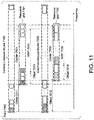
- FIG. 11 is a diagram showing an example of communication between a base station apparatus 3 and a terminal apparatus 1 according to one aspect of the present embodiment.
- the horizontal axis indicates frequency.
- a point 7000 is an identifier for identifying a certain subcarrier.
- the point 7000 is referred to as a point A.
- a set of common resource blocks 7100 includes one or more resource blocks for a subcarrier spacing configuration ⁇ 1 .
- the point 7000 may be given at least based on a higher layer parameter.
- the point A may be given at least based on a subcarrier #0 with the smallest index among subcarriers mapped with the PBCH, an offset parameter A, and an offset parameter B.
- the subcarrier #0 with the smallest index among subcarriers mapped with PBCH is also referred to as a point 6998.
- the subcarrier #0 may be a subcarrier of an index 0.
- the subcarrier #0 of a certain resource block may be a subcarrier mapped to a position of the lowest frequency in the certain resource block.
- the offset parameter A may be given at least based on one or both of a parameter included in the PBCH and/or scrambling of a DMRS associated with the PBCH.
- the offset parameter A may be an offset value indicating the difference between a point 6998 and a point 6999.
- the offset value may be given by a number of subcarriers.
- the point 6999 may be a subcarrier #0 in a resource block of an index N CRB SSB in the set of common resource blocks 7100.
- the index N CRB SSB may be given at least based on a higher layer parameter.
- the index N CRB SSB may be given at least based on an SIB 1.
- a reference point of the set of common resource blocks 7100 is a resource block including the point 7000 and corresponding to the subcarrier spacing configuration ⁇ 1 .
- the block indicated by upper-right diagonal lines indicates a reference point of the set of common resource blocks 7100.
- An offset 7011 shown in FIG. 11 is at least used to indicate a resource grid 7101 given for a subcarrier spacing setting ⁇ 1 and a carrier 7001.
- the block indicated by a grid pattern shown in FIG. 11 indicates a reference point of the resource grid 7101.
- the reference point of the resource grid 7101 corresponds to a common resource block of an index N 7011 of the set of common resource blocks 7100.
- the N 7011 is an offset value indicating the difference of the resource blocks from the reference point of the set of common resource blocks 7100 to the reference point of the resource grid 7101.
- the N 7011 is a value of the offset 7011.
- An offset 7013 shown in FIG. 11 is at least used to indicate a BWP 7003.
- the resource block indicated by horizontal lines shown in FIG. 11 indicates a reference point of the BWP 7003.
- the reference point of the BWP 7003 may be a physical resource block of an index 0.
- a set of common resource blocks 7200 includes one or more resource blocks for a subcarrier spacing configuration ⁇ 2 .
- a reference point of the set of common resource blocks 7200 is a resource block including the point 7000 and corresponding to the subcarrier spacing configuration ⁇ 2 .
- the block indicated by upper-left diagonal lines indicates a reference point of the set of common resource blocks 7200.
- An offset 7012 shown in FIG. 11 is at least used to indicate a resource grid 7102 given for a subcarrier spacing setting ⁇ 2 and a carrier 7002.
- the block indicated by vertical lines shown in FIG. 11 indicates a reference point of the resource grid 7102.
- the reference point of the resource grid 7102 corresponds to a common resource block of an index N 7012 of the set of common resource blocks 7200.
- the N 7012 is an offset value indicating the difference of the resource blocks from the reference point of the set of common resource blocks 7200 to the reference point of the resource grid 7102.
- the N 7012 is a value of the offset 7012.
- the relationship between the subcarrier spacing configurations ⁇ 1 and ⁇ 2 may not be limited to the example shown in FIG. 11 .
- An offset 7014 shown in FIG. 11 is at least used to indicate a BWP 7004.
- the resource block indicated by a dot pattern shown in FIG. 11 indicates a reference point of the BWP 7004.
- the reference point of the BWP 7004 may be a physical resource block of an index 0.
- a certain transmission bandwidth configuration may be correspond to a certain carrier.
- the reference point of a certain transmission bandwidth configuration may coincide with the reference point of a resource grid of a certain carrier corresponding to the certain transmission bandwidth configuration.
- a set of resource blocks included in the certain transmission bandwidth configuration may coincide with a set of resource blocks included in a resource grid of the carrier corresponding to the certain transmission bandwidth configuration.
- the configuration of the resource grid for a certain carrier may be given at least based on a higher layer parameter (SCS-specificCarrier) associated with the carrier.
- the higher layer parameter associated with the carrier may include a parameter indicating a subcarrier spacing configuration ⁇ of the carrier.
- the higher layer parameter associated with the carrier for the subcarrier spacing configuration ⁇ may include at least a parameter indicating an offset from a reference point of the common resource blocks for the subcarrier spacing configuration ⁇ to a reference point of a resource grid for the carrier.
- the higher layer parameter associated with the carrier for a certain subcarrier spacing configuration ⁇ may include at least a parameter indicating the number of resource blocks included in the carrier.
- the higher layer parameter associated with the carrier may be included in a common RRC parameter or in a dedicated RRC parameter.
- the transmission bandwidth configuration 8001 may be given at least based on the dedicated RRC parameter.
- the transmission bandwidth configuration 8001 may be given at least based on a common RRC parameter including a higher layer parameter associated with the carrier.
- the common RRC parameter including a higher layer parameter associated with the carrier may be included in an SIB1.
- the transmission bandwidth configuration 8001 may be given at least based on an initial downlink BWP.
- the transmission bandwidth configuration 8001 may be given at least based on a higher layer parameter associated with the carrier and included in the dedicated RRC parameter.
- the initial downlink BWP may be a downlink BWP of an index 0.
- a parameter for configuring the initial downlink BWP may be included in the common RRC parameter.
- a parameter for configuring the initial downlink BWP may be included in an SIB1.
- control resource set #0 may be a control resource set of an index 0.
- a parameter for configuring the control resource set #0 may be included in the common RRC parameter.
- a parameter for configuring the control resource set #0 may be included in an MIB.
- the configuration of the control resource set #0 may be given at least based on four bits of the MSBs (Most Significant Bits) of a higher layer parameter PDCCH-ConfigSIB1.
- the fact that the terminal apparatus 1 supports a certain frequency band may mean that the terminal apparatus 1 has a function of transmitting and/or receiving signals in the frequency band.
- the fact that the terminal apparatus 1 does not support a certain frequency band may mean that the terminal apparatus 1 does not have at least one of functions of transmitting and receiving signals in the frequency band.
- the transmission bandwidth configuration 8001 may be given at least based on the higher layer parameter associated with the second carrier.
- a resource grid for a carrier may be given at least based on a higher layer parameter associated with a second carrier and included in a common RRC parameter regardless of whether a dedicated RRC parameter including a higher layer parameter associated with a first carrier is given.
- a resource grid for a carrier may be given at least based on a higher layer parameter associated with a second carrier and included in a common RRC parameter.
- the configuration of an initial downlink BWP for a certain subcarrier spacing configuration ⁇ may be given at least based on an offset value from the reference point of a resource grid for a carrier for the certain subcarrier spacing configuration ⁇ to the reference point of the initial downlink BWP.
- the offset value may be included in common RRC signaling.
- the reference point of the resource grid for the carrier may be given at least based on a higher layer parameter associated with a second carrier and included in a common RRC parameter.
- the configuration of a downlink BWP, which is different from an initial downlink BWP, for a certain subcarrier spacing configuration ⁇ may be given at least based on an offset value from the reference point of a resource grid for a carrier for the certain subcarrier spacing configuration ⁇ to the reference point of the downlink BWP.
- the offset value may be included in a dedicated RRC parameter.
- the reference point of the resource grid for the carrier may be given at least based on a higher layer parameter associated with a first carrier and included in a dedicated RRC parameter.
- the configuration of a downlink BWP for a certain subcarrier spacing configuration ⁇ may be given at least based on an offset value from the reference point of a resource grid for a carrier for the certain subcarrier spacing configuration ⁇ to the reference point of the downlink BWP.
- the offset value may be included in a higher layer parameter.
- the reference point of the resource grid for the carrier may be given at least based on a higher layer parameter associated with a second carrier and included in a common RRC parameter.
- the configuration of an initial uplink BWP for a certain subcarrier spacing configuration ⁇ may be given at least based on an offset value from the reference point of a resource grid for a carrier for the certain subcarrier spacing configuration ⁇ to the reference point of the initial uplink BWP.
- the offset value may be included in common RRC signaling.
- the reference point of the resource grid for the carrier may be given at least based on a higher layer parameter associated with a second carrier and included in a common RRC parameter.
- the configuration of an uplink BWP, which is different from an initial uplink BWP, for a certain subcarrier spacing configuration ⁇ may be given at least based on an offset value from the reference point of a resource grid for a carrier for the certain subcarrier spacing configuration ⁇ to the reference point of the uplink BWP.
- the offset value may be included in a dedicated RRC parameter.
- the reference point of the resource grid for the carrier may be given at least based on a higher layer parameter associated with a first carrier and included in a dedicated RRC parameter.
- the configuration of a uplink BWP for a certain subcarrier spacing configuration ⁇ may be given at least based on an offset value from the reference point of a resource grid for a carrier for the certain subcarrier spacing configuration ⁇ to the reference point of the uplink BWP.
- the offset value may be included in a higher layer parameter.
- the reference point of the resource grid for the carrier may be given at least based on a higher layer parameter associated with a second carrier and included in a common RRC parameter.
- a program operating in the base station apparatus 3 and the terminal apparatus 1 according to the present invention may be a program that controls a central processing unit (CPU) and the like (i.e., a program to cause a computer to function) to implement the functions of the above-described embodiment according to the present invention.
- CPU central processing unit
- the information processed by these apparatuses is temporarily stored in RAM (Random Access Memory) while being processed, then stored in various types of ROM (Read Only Memory) such as a Flash ROM and HDD (Hard Disk Drive), and read, modified or rewritten by the CPU as necessary.
- a part of the terminal apparatus 1 and the base station apparatus 3 according to the above embodiment may be realized by a computer. In that case, it may be realized by recording a program for realizing the control function on a computer-readable recording medium, and causing a computer system to read the program recorded on the recording medium for execution.
- the "computer system” mentioned here indicates a computer system built into the terminal apparatus 1 or the base station apparatus 3, and the computer system may include an OS and hardware components such as a peripheral apparatus.
- the "computer-readable recording medium” indicates a portable medium such as a flexible disk, an optical disk, a ROM, a CD-ROM, and the like, and a storage device such as a hard disk built into the computer system.
- the "computer-readable recording medium” may include a recording medium for dynamically storing programs for a short time, such as a communication line in the case of transmitting the programs via a network such as the internet or a communication line such as a telephone line, and may include a recording medium for storing the programs for a fixed period of time, such as a volatile memory within a computer system of a server or a client in such a case.
- the above-mentioned program may be configured to realize some of the functions described above, and also may be configured to be capable of realizing the functions described above in combination with a program already recorded in the computer system.
- the base station apparatus 3 may be implemented as an aggregation (apparatus group) including multiple apparatuses.
- Each of the apparatuses constituting such an apparatus group may include some or all portions of each function or each functional block of the base station apparatus 3 according to the above-mentioned embodiment.
- the apparatus group may be required to have each general function or each functional block of the base station apparatus 3.
- the terminal apparatus 1 according to the above-mentioned embodiment can also communicate with a base station apparatus implemented as aggregation.
- the base station apparatus 3 may serve as an EUTRAN (Evolved Universal Terrestrial Radio Access Network) and/or NG-RAN (NextGen RAN or NR RAN).
- EUTRAN Evolved Universal Terrestrial Radio Access Network
- NG-RAN NextGen RAN or NR RAN
- the base station apparatus 3 according to the above-mentioned embodiment may have some or all of the functions of a higher layer node with respect to an eNodeB and/or gNB.
- some or all portions of the terminal apparatus 1 and the base station apparatus 3 may be implemented as an LSI typically functioning as an integrated circuit or may be implemented as .a chip set.
- Each of the functional blocks of the terminal apparatus 1 and the base station apparatus 3 may be individually implemented as a chip, or some or all of the functional blocks of the same may be integrated into a chip.
- a circuit integration technique is not limited to the LSI, and may be implemented by a dedicated circuit or a general-purpose processor.
- a circuit integration technology may appear to replace the LSI technology, and an integrated circuit based on such a technology can also be used.
- the terminal apparatus has been described as an example of a communication apparatus, but the present invention is not limited to such a terminal apparatus, and is applicable to a fixed-type or a stationary-type electronic equipment installed indoors or outdoors, for example, terminal apparatuses or communication apparatuses such as AV equipment, kitchen equipment, cleaning/washing equipment, an air-conditioning equipment, office equipment, a vending machine, and other household apparatuses.
- terminal apparatuses or communication apparatuses such as AV equipment, kitchen equipment, cleaning/washing equipment, an air-conditioning equipment, office equipment, a vending machine, and other household apparatuses.
- One aspect of the present invention can be applied to, for example, a communication system, a communication equipment (e.g., a mobile phone apparatus, a base station apparatus, a wireless LAN apparatus, or a sensor apparatus), an integrated circuit (e.g., a communication chip), a program, or the like.
- a communication equipment e.g., a mobile phone apparatus, a base station apparatus, a wireless LAN apparatus, or a sensor apparatus
- an integrated circuit e.g., a communication chip
- a program e.g., a program, or the like.
Landscapes
- Engineering & Computer Science (AREA)
- Signal Processing (AREA)
- Computer Networks & Wireless Communication (AREA)
- Mobile Radio Communication Systems (AREA)
Abstract
Description
- The present invention relates to a terminal apparatus, a base station apparatus, and a communication method. The present application claims priority based on
Japanese Patent Application No. 2019-10206 filed on January 24, 2019 - A radio access scheme and a wireless network for cellular mobile communication (hereinafter, referred to as "Long Term Evolution (LTE)" or "Evolved Universal Terrestrial Radio Access (EUTRA)") have been studied in the 3rd Generation Partnership Project (3GPP). In LTE, a base station apparatus is referred to as an eNodeB, and a terminal apparatus is also referred to as a UE (User Equipment). LTE is a cellular communication system in which areas covered by a plurality of base station apparatuses are arranged in a cell-like configuration. A single base station apparatus may also manage multiple serving cells.
- In the 3GPP, a next generation standard (New Radio or NR) (NPL 1) is being studied in order to make a proposal for International Mobile Telecommunication (IMT)-2020, a standard for a next-generation mobile communication system, standardized by the International Telecommunication Union (ITU). NR is required to satisfy requirements for three scenarios including eMBB (enhanced Mobile BroadBand), mMTC (massive Machine Type Communication), and URLLC (Ultra Reliable and Low Latency Communication) in a single technology framework.
- NPL 1: "New SID proposal: Study on New Radio Access Technology", RP-160671, NTT docomo, 3GPP TSG RAN Meeting # 71, Goteborg, Sweden, March 7th-10th, 2016.
- The present invention provides a terminal apparatus that performs communication efficiently, a communication method for the terminal apparatus, a base station apparatus that performs communication efficiently, and a communication method for the base station apparatus.
- (1) The first aspect of the present invention is to provide a terminal apparatus comprising: a higher layer processing unit configured to receive a radio resource control parameter specific to the terminal apparatus and related to a transmission bandwidth configuration; and a reception unit configured to receive a downlink shared channel in an active downlink bandwidth part of a carrier corresponding to the transmission bandwidth configuration. When the radio resource control parameter specific to the terminal apparatus is not received, the transmission bandwidth configuration is given at least based on an initial downlink bandwidth part.
- (2) The second aspect of the present invention is to provide a base station apparatus comprising: a higher layer processing unit configured to transmit a radio resource control parameter specific to the terminal apparatus and related to a transmission bandwidth configuration; and a transmission unit configured to transmit a downlink shared channel in an active downlink bandwidth part of a carrier corresponding to the transmission bandwidth configuration. When the radio resource control parameter specific to the terminal apparatus is not transmitted, the transmission bandwidth configuration is given at least based on an initial downlink bandwidth part.
- (3) The third aspect of the present invention is to provide a communication method for a terminal apparatus having a computer. The communication method is performed by the computer and comprises: performing a higher layer processing process to receive a radio resource control parameter specific to the terminal apparatus and related to a transmission bandwidth configuration; and performing a reception process to receive a downlink shared channel in an active downlink bandwidth part of a carrier corresponding to the transmission bandwidth configuration. When the radio resource control parameter specific to the terminal apparatus is not received, the transmission bandwidth configuration is given at least based on an initial downlink bandwidth part.
- (4) The fourth aspect of the present invention is to provide a communication method for a base station apparatus having a computer. The communication method is performed by the computer and comprises: performing a higher layer processing process to transmit a radio resource control parameter specific to the terminal apparatus and related to a transmission bandwidth configuration; and performing a transmission process to transmit a downlink shared channel in an active downlink bandwidth part of a carrier corresponding to the transmission bandwidth configuration. When the radio resource control parameter specific to the terminal apparatus is not transmitted, the transmission bandwidth configuration is given at least based on an initial downlink bandwidth part.
- According to one aspects of the present invention, the terminal apparatus can perform communication efficiently. In addition, the base station apparatus can perform communication efficiently.
-
-
FIG. 1 is a conceptual diagram of a wireless communication system according to one aspect of the present embodiment. -
FIG. 2A is an example showing a relationship among N slot symb, a subcarrier spacing configuration µ, and a CP configuration according to one aspect of the present embodiment. -
FIG. 2B is an example showing a relationship among N slot symb, a subcarrier spacing configuration µ, and a CP configuration according to one aspect of the present embodiment. -
FIG. 3 is a schematic diagram showing an example of a resource grid in a subframe according to one aspect of the present embodiment. -
FIG. 4 is a schematic diagram showing an example of a relationship between a PUCCH format and the length N PUCCH symb of the PUCCH format according to one aspect of the present embodiment. -
FIG. 5 is a diagram showing an example of a monitoring occasion of a search space set according to one aspect of the present embodiment. -
FIG. 6 is a schematic block diagram showing a configuration of aterminal apparatus 1 according to one aspect of the present embodiment. -
FIG. 7 is a schematic block diagram showing a configuration of abase station apparatus 3 according to one aspect of the present embodiment. -
FIG. 8 is a diagram showing an example of a carrier configuration according to one aspect of the present embodiment. -
FIG. 9 is a diagram showing a configuration example of a maximum number N RB of resource blocks of a transmission bandwidth configuration 8001 according to one aspect of the present embodiment. -
FIG. 10 is a diagram showing a configuration example of a minimum value of aguard band 8003 configured for achannel bandwidth 8000 according to one aspect of the present embodiment. -
FIG. 11 is a diagram showing an example of communication between abase station apparatus 3 and aterminal apparatus 1 according to one aspect of the present embodiment. - Hereinafter, the embodiments of the present invention will be described.
- The term "A and/or B" may be a term that includes "A", "B", or "A and B".
-
FIG. 1 is a conceptual diagram of a wireless communication system according to one aspect of the present embodiment. InFIG. 1 , the wireless communication system includesterminal apparatuses 1A to 1C and a base station apparatus 3 (BS #3: Base Station #3). Hereinafter, theterminal apparatuses 1A to 1C are refer to as a terminal apparatus 1 (UE #1: User Equipment #1). - The
base station apparatus 3 may be configured to include one or both of an MCG (Master Cell Group) and an SCG (Secondary Cell Group). The MCG is a group of serving cells that include at least a PCell (Primary Cell). The SCG is a group of serving cells that include at least a PSCell (Primary Secondary Cell). The PCell may be a serving cell given based on an initial connection. The PCell may also be a serving cell where an initial connection is performed. The MCG may also include one or more SCells (Secondary cells). The SCG may also include one or more SCells. The PCell is also referred to as a primary cell. The PScell is also referred to as a primary secondary cell. The SCell is also referred to as a secondary cell. - The MCG may also include serving cells in an EUTRA. The SCG may also include serving cells in a next generation standard (New Radio (NR)).
- A frame configuration will be described below.
- In a wireless communication system according to one aspect of the present embodiment, at least OFDM (Orthogonal Frequency Division Multiplexing) is used. An OFDM symbol is a unit of an OFDM time domain. An OFDM symbol includes at least one or more subcarriers. An OFDM symbol may also be converted into a time-continuous signal in generation of a baseband signal. In a downlink, at least CP-OFDM (Cyclic Prefix Orthogonal Frequency Division Multiplexing) is used. In an uplink, either CP-OFDM or DFT-s-OFDM (Discrete Fourier Transform -Spread - Orthogonal Frequency Division Multiplexing) is used. The DFT-s-OFDM is given by applying transform precoding to the CP-OFDM.
- The OFDM symbol may also be a term including a CP attached to the OFDM symbol. In other words, a certain OFDM symbol may be configured to include the certain OFDM symbol and a CP attached to the certain OFDM symbol.
- A subcarrier spacing (SCS) may be given by the subcarrier spacing Δf=2µ • 15kHz. For example, a subcarrier spacing configuration µ may be configured to be any one of 0, 1, 2, 3, 4, and/or 5. For a certain BWP (BandWidth Part), the subcarrier spacing configuration µ may be given by a higher layer parameter.
- In a wireless communication system according to one aspect of the present embodiment, a time unit Tc may be used to represent the length of a time domain. The time unit Tc may be given by Tc=1 /(Δfmax • Nf). Δfmax may be the maximum value of the subcarrier spacing supported in the wireless communication system according to one aspect of the present embodiment. Δfmax may be Δfmax=480 kHz. Nf may be Nf=4096. A constant κ is κ=Δfmax • Nf / (ΔfrefNf,ref)=64. Δfref may be 15 kHz. Nf,ref may be 2048.
- The constant κ may be a value indicating a relationship between a reference subcarrier spacing and Tc. The constant κ may be used for a length of a subframe. The number of slots included in the subframe may be given at least based on the constant κ. Δfref is the reference subcarrier spacing, and Nf,ref is a value corresponding to the reference subcarrier spacing.
- The transmission of a signal on a downlink and/or the transmission of a signal on an uplink may be organized into 10ms frames. A frame includes 10 subframes. The length of a subframe is 1 ms. The length of a frame may be given independently of the subcarrier spacing Δf. In other words, the length of a frame may be given independently of µ. The length of a subframe may be given independently of the subcarrier spacing Δf. In other words, the length of a subframe may be given independently of µ.
- For a certain subcarrier spacing configuration µ, the number and indexes of slots included in a subframe may be given. For example, a slot number nµ s may be given by an integer value in ascending order in a range from 0 to N subframe, µ slot―1 within a subframe. For a subcarrier spacing configuration µ, the number and indexes of slots included in a frame may be given. In addition, a slot number nµ s may be given by an integer value in ascending order in a range from 0 to N frame, µ slot―1 within a frame. N slot symb consecutive OFDM symbols may be included in one slot. N slot symb may be given at least based on some or all of CP (Cyclic Prefix) configurations. The CP configuration may be given at least based on a higher layer parameter. The CP configuration may be given at least based on dedicated RRC signaling. The slot number is also referred to as a slot index.
-
FIG. 2 is an example showing a relationship among N slot symb, a subcarrier spacing configuration µ, and a CP configuration according to one aspect of the present embodiment. InFIG. 2A , for example, when the subcarrier spacing configuration µ is 2 and the CP configuration is a normal CP (normal cyclic prefix), N slot symb =14, N frame, µ slot=40, and N subframe,µ slot=4. In addition, inFIG. 2B , for example, when the subcarrier spacing configuration µ is 2 and the CP configuration is an extended CP (extended cyclic prefix), N slot symb =12, N frame, µ slot =40, and N subframe,µ slot =4. - Physical resources will be described below.
- An antenna port is defined in such a manner that a channel on which a symbol is transmitted on one antenna port can be inferred from a channel on which another symbol is transmitted on the same antenna port. In a case that a large scale property of a channel on which a symbol is transmitted on one antenna port can be inferred from a channel on which a symbol is transmitted on another antenna port, the two antenna ports are referred to as being QCL (Quasi Co-Located). The large scale property may include at least a long term property of a channel. The large scale property may include at least some or all of delay spread, Doppler spread, Doppler shift, average gain, average delay, and spatial Rx parameters. The fact that a first antenna port and a second antenna port are QCL with respect to a beam parameter may mean that a reception beam assumed by the reception side for the first antenna port may be the same as a reception beam assumed by the reception side for the second antenna port. The fact that a first antenna port and a second antenna port are QCL with respect to a beam parameter may mean that a transmission beam assumed by the reception side for the first antenna port may be the same as a transmission beam assumed by the reception side for the second antenna port. In a case that a large scale property of a channel on which a symbol on one antenna port is transmitted can be inferred from a channel on which a symbol on another antenna port is transmitted, the
terminal apparatus 1 may assume the two antenna ports to be QCL. The fact that two antenna ports are QCL may mean that the two antenna ports are assumed to be QCL. - A resource grid defined by N size, µ grid, x N RB SC subcarriers and N subframe, µ symb OFDM symbols is given for a subcarrier spacing configuration and a carrier set. N size, µ grid, x may indicate the number of resource blocks given for the subcarrier spacing configuration µ. N size, µ grid, x may also represent the bandwidth of a carrier. N size, µ grid, x may also correspond to the value of a higher layer parameter CarrierBandwidth. The carrier x may indicate either a downlink carrier or an uplink carrier. In other words, x may be either "DL" or "UL". N RB SC may indicate the number of subcarriers included in one resource block. N RB SC may be 12. At least one resource grid may be given for each antenna port p and/or for each subcarrier spacing configuration µ and/or for each transmission direction configuration. The transmission direction includes at least a downlink (DL) and an uplink (UL). Hereinafter, a set of parameters including at least some or all of the antenna port p, the subcarrier spacing configuration µ, and the transmission direction configuration is also referred to as a first radio parameter set. In other words, one resource grid may be given for each first radio parameter set.
- A resource block is a general term for a common resource block and a physical resource block. For example, the index of the resource block may also be given in ascending order from a reference point. A resource block corresponding to a certain subcarrier spacing configuration µ may be a resource block including resource elements given based on the subcarrier spacing configuration µ.
- In the downlink, a carrier included in a serving cell is referred to as a downlink carrier (or a downlink component carrier). In the uplink, a carrier included in a serving cell is referred to as an uplink carrier (an uplink component carrier). The downlink component carrier and the uplink component carrier are collectively referred to as a component carrier (or a carrier).
- The type of the serving cell may be any one of a PCell, a PSCell, and a SCell. The PCell may be a serving cell identified at least based on a cell ID acquired from an SS/PBCH in an initial connection. The PCell may be at least configured with a RACH resource. The SCell may be a serving cell used in carrier aggregation. The SCell may be a serving cell given at least based on dedicated RRC signaling.
- Each element in the resource grid given for each first radio parameter set is referred to as a resource element. The resource element is identified at least based on a frequency domain index ksc and a time domain index lsym. For a certain first radio parameter set, the resource element is identified at least based on a frequency domain index ksc and a time domain index lsym. The resource element identified by the frequency domain index ksc and the time domain index lsym is also referred to as a resource element (ksc, lsym). The frequency domain index ksc indicates any of values from 0 to N µ RB N RB sc-1. N µ RB may be the number of resource blocks given for the the subcarrier spacing configuration µ. N µ RB may also be N size, µ grid, x· N RB SC may be the number of subcarriers included in a resource block, and N RB SC=12. The frequency domain index ksc may correspond to a subcarrier index ksc. The time domain index lsym may correspond to an OFDM symbol index lsym.
-
FIG. 3 is a schematic diagram showing an example of a resource grid in a subframe according to one aspect of the present embodiment. In the resource grid ofFIG. 3 , a horizontal axis is a time domain index lsym, and a vertical axis is a frequency domain index ksc. In one subframe, the frequency domain of the resource grid includes N µ RB N RB SC subcarriers. In one subframe, the time domain of the resource grid may include 14 • 2µ OFDM symbols. One resource block includes N RB SC subcarriers. The time domain of the resource block may correspond to one OFDM symbol. The time domain of the resource block may also correspond to fourteen OFDM symbols. The time domain of the resource block may correspond to one or more time slots. The time domain of the resource block may also correspond to one subframe. - The frequency domain of the resource grid including N µ RB N RB SC subcarriers may correspond to the frequency domain of the resource grid including N µ RB resource blocks.
- The
terminal apparatus 1 may be indicated to perform transmission/ reception using only a subset of the resource grid. The subset of a resource grid is also referred to as a BWP and may be given based on at least some or all of higher layer parameters and/or DCI. The BWP is also referred to as a carrier bandwidth part. The BWP is also referred to as a BandWidth Part. Theterminal apparatus 1 may not be indicated to perform transmission and/or reception using all sets of the resource grids. Theterminal apparatus 1 may be indicated to perform transmission/ reception using some frequency resources within the resource grid. One BWP may include a plurality of resource blocks in the frequency domain. One BWP may include a plurality of consecutive resource blocks in the frequency domain. The BWP configured for a downlink carrier is also referred to as a downlink BWP. The BWP configured for an uplink carrier is also referred to as an uplink BWP. The BWP may also be a subset of a carrier frequency band. - One or more downlink BWPs may be configured for each of serving cells. One or more uplink BWPs may be configured for each of serving cells.
- One downlink BWP of the one or more downlink BWPs configured for a serving cell may be configured (or activated) as an active downlink BWP. A downlink BWP switch is used to deactivate one active downlink BWP and activate an inactive downlink BWP other than the one active downlink BWP. The downlink BWP switch may be controlled by a BWP field included in downlink control information. The downlink BWP switch may also be controlled based on a higher layer parameter.
- DL-SCH may be received in an active downlink BWP. PDCCH may be monitored in an active downlink BWP. PDSCH may be received in an active downlink BWP. Some or all of a PDSCH, a PDCCH, and a CSI-RS may not be received outside of an active downlink BWP.
- DL-SCH may not be received in an inactive downlink BWP. PDCCH may not be monitored in an inactive downlink BWP. CSI for an inactive downlink BWP may not be reported.
- Two or more downlink BWPs of the one or more downlink BWPs configured for a serving cell may not be configured as active downlink BWPs. At a certain time, one downlink BWP is active.
- One uplink BWP of the one or more uplink BWPs configured for a serving cell may be configured (or activated) as an active uplink BWP. An uplink BWP switch is used to deactivate one active uplink BWP and activate an inactive uplink BWP other than the one active uplink BWP. The uplink BWP switch may be controlled by a BWP field included in downlink control information. The uplink BWP switch may also be controlled based on a higher layer parameter.
- UL-SCH may be transmitted in an active uplink BWP. PUCCH may be transmitted in an active uplink BWP. PRACH may be transmitted in an active uplink BWP. SRS may be transmitted in an active uplink BWP. Some or all of a PUSCH and a PUCCH may not be transmitted outside of an active uplink BWP.
- UL-SCH is not transmitted in an inactive uplink BWP. PUCCH is not transmitted in an in active uplink BWP. PRACH is not transmitted in an inactive uplink BWP. SRS is not transmitted in an inactive uplink BWP.
- Two or more uplink BWPs of the one or more uplink BWPs configured for a serving cell may not be configured as active uplink BWPs. At a certain time, one uplink BWP may be active.
- The higher layer parameter is a parameter included in a higher layer signal. The higher layer signal may be RRC (Radio Resource Control) signaling or MAC CE (Medium Access Control Control Element). Here, the higher layer signal may be an RRC layer signal or may be a MAC layer signal.
- The higher layer signal may be common RRC signaling. The common RRC signaling may include at least some or all of the following features C1 to C3.
- Feature C1) being mapped to a BCCH logical channel or a CCCH logical channel
- Feature C2) including at least a ReconfigrationWithSync information element
- Feature C3) being mapped to a PBCH and/or system information
- The ReconfigrationWithSync information element may include information indicating a configuration commonly used in the serving cell. The configuration commonly used in the serving cell may include at least a PRACH configuration. The PRACH configuration may indicate at least one or more random access preamble indexes. The PRACH configuration may indicate at least a PRACH time/frequency resource.
- The common RRC signaling may include at least a common RRC parameter. The common RRC parameter may also be a cell-specific parameter that is commonly used in the serving cell.
- The higher layer signal may be dedicated RRC signaling. The dedicated RRC signaling may include at least some or all of the following features D1 to D2.
- Feature D1) being mapped to a DCCH logical channel
- Feature D2) not including at least a ReconfigrationWithSync information element
- For example, an MIB (Master Information Block) and an SIB (System Information Block) may be common RRC signaling. In addition, a higher layer message that is mapped to the DCCH logical channel and includes at least the ReconfigurationWithSync information element may be common RRC signaling. In addition, a higher layer message that is mapped to the DCCH logical channel and does not include the ReconfigurationWithSync information element may be included in the dedicated RRC signaling.
- The SIB may at least indicate a time index of an SS (Synchronization Signal) block. The SS block is also referred to as an SS/PBCH block. The SIB may include at least information related to a PRACH resource. The SIB may include at least information related to an initial connection configuration.
- The ReconfigrationWithSync information element may include at least information related to a PRACH resource (or a RACH resource). The ReconfigurationWithSync information element may include at least information related to a random access configuration.
- The dedicated RRC signaling may include at least a dedicated RRC parameter. The dedicated RRC parameter may be a UE-specific parameter dedicated to the
terminal apparatus 1. - The common RRC parameter and the dedicated RRC parameter are referred to as higher layer parameters.
- A physical channel and a physical signal according to various aspects of the present embodiment will be described below.
- One physical channel may be mapped to one serving cell. One physical channel may be mapped to one carrier band part configured for one carrier included one a serving cell.
- An uplink physical channel may correspond to a set of resource elements that transmit information generated in a higher layer. The uplink physical channel may be a physical channel used in an uplink carrier. In a wireless communication system according to one aspect of the present embodiment, at least some or all of the following uplink physical channels may be used.
- PUCCH (Physical Uplink Control CHannel)
- PUSCH (Physical Uplink Shared CHannel)
- PRACH (Physical Random Access CHannel)
- The PUCCH may be used to transmit uplink control information (UCI). The uplink control information includes some or all of Channel State Information (CSI), a Scheduling Request (SR), and a Hybrid Automatic Repeat request ACKnowledgement (HARQ-ACK) information.
- The uplink control information may be multiplexed on the PUCCH. The multiplexed PUCCH may be transmitted.
- The uplink control information may be mapped to the PUCCH.
- The HARQ-ACK information may include at least a HARQ-ACK bit corresponding to a transport block (Transport Block (TB), Medium Access Control Protocol Data Unit (MAC PDU), Downlink-Shared Channel (DL-SCH), Uplink-Shared Channel (UL-SCH), or Physical Downlink Shared Channel (PDSCH)). The HARQ-ACK bit may indicate an ACK (acknowledgement) or a NACK (negative-acknowledgement) corresponding to the transport block. The ACK may be a value indicating that decoding of the transport block is successfully completed. The NACK may be a value indicating that decoding of the transport block is not successfully completed. The HARQ-ACK information may correspond to a HARQ-ACK codebook that includes one or more HARQ-ACK bits. The fact that the HARQ-ACK bit corresponds to one or more transport blocks may mean that the HARQ-ACK bit corresponds to a PDSCH including the one or more transport blocks.
- The HARQ-ACK bit may indicate an ACK or a NACK corresponding to one CBG (Code Block Group) included in the transport block. The HARQ-ACK information is also referred to as a HARQ-ACK, a HARQ feedback, HARQ information, HARQ control information, and a HARQ-ACK message.
- A scheduling request (SR) may be at least used to request a PUSCH (or UL-SCH) resource for initial transmission (or new transmission). A scheduling request bit may be used to indicate either a positive SR or a negative SR. The fact that the scheduling request bit indicates a positive SR is also referred to as "transmitting a positive SR". The positive SR may indicate that a PUSCH resource for initial transmission is requested by the
terminal apparatus 1. The positive SR may indicate that a scheduling request is triggered by a higher layer. The positive SR may be transmitted in a case that a scheduling request is instructed by a higher layer to be transmitted. The fact that the scheduling request bit indicates a negative SR is also referred to as "transmitting a negative SR". The negative SR may indicate that a PUSCH resource for initial transmission is not requested by theterminal apparatus 1. The negative SR may indicate that a scheduling request is not triggered by a higher layer. The negative SR may be transmitted in a case that a scheduling request is not instructed by a higher layer to be transmitted. - The scheduling request bit may be used to indicate either a positive SR or a negative SR for any one or more SR configurations. Each of the one or more SR configurations may correspond to one or more logical channels, respectively. A positive SR for a certain SR configuration may be a positive SR for any or all of the one or more logical channels corresponding to the certain SR configuration. A negative SR may not correspond to a specific SR configuration. Indicating a negative SR may mean indicating a negative SR for all SR configurations.
- The SR configuration may be a scheduling request ID. The scheduling request ID may be given by a higher layer parameter.
- The channel state information may include at least some or all of a Channel Quality Indicator (CQI), a Precoder Matrix Indicator (PMI), and a Rank Indicator (RI). The CQI is an indicator related to channel quality (for example, propagation strength), and the PMI is an indicator related to a precoder. The RI is an indicator related to a transmission rank (or the number of transmission layers).
- The channel state information may be given at least based on receiving a physical signal (e.g., CSI-RS) that is at least used for channel measurement. The channel state information may include a value selected by the
terminal apparatus 1. The channel state information may be selected by theterminal apparatus 1 at least based on receiving a physical signal that is at least used for channel measurement. The channel measurement includes interference measurement. - A channel state information report is a report of the channel state information. The channel state information report may include a
CSI part 1 and/or aCSI part 2. TheCSI part 1 may be configured to include at least some or all of wideband channel quality information (wideband CQI), a wideband precoder matrix indicator (wideband PMI), and a rank indicator. The number of bits of theCSI part 1 multiplexed on the PUCCH may be a predetermined value regardless of a value of the rank indicator of the channel state information report. The number of bits of theCSI part 2 multiplexed on the PUCCH may be given at least based on the value of the rank indicator of the channel state information report. The rank indicator of the channel state information report may be a value of the rank indicator used to calculate the channel state information report. The rank indicator of the channel state information may be a value indicated by a rank indicator field included in the channel state information report. - A set of rank indicators permitted in the channel state information report may be some or all of 1 to 8. The set of rank indicators permitted in the channel state information report may be given at least based on a higher layer parameter RankRestriction. In a case that the set of rank indicators permitted in the channel state information report includes only one value, the rank indicator of the channel state information report may be the one value.
- A priority may be configured for the channel state information report. The priority of the channel state information report may be given at least based on some or all of a configuration related to a time domain behavior of the channel state information report, a type of content of the channel state information report, an index of the channel state information report, and/or an index of a serving cell configured with measurement of the channel state information report.
- The configuration related to the time domain behavior of the channel state information report may be a configuration indicating whether the channel state information report is performed aperiodically, semi-persistently, or semi-statically.
- The type of content of the channel state information report may indicate whether the channel state information report includes a Reference Signals Received Power (RSRP) of a
layer 1. - The index of the channel state information report may be given by a higher layer parameter.
- The PUCCH supports PUCCH formats (
PUCCH format 0 to PUCCH format 4). The PUCCH format may be transmitted on the PUCCH. The fact that a PUCCH format is transmitted may mean that a PUCCH is transmitted. -
FIG. 4 is a schematic diagram showing an example of a relationship between a PUCCH format and the length N PUCCH Symb of the PUCCH format according to one aspect of the present embodiment. The length N PUCCH Symb ofPUCCH format 0 is 1 or 2 OFDM symbols. The length N PUCCH Symb ofPUCCH format 1 is any of 4 to 14 OFDM symbols. The length N PUCCH Symb ofPUCCH format 2 is 1 or 2 OFDM symbols. The length N PUCCH Symb ofPUCCH format 3 is any of 4 to 14 OFDM symbols. The length N PUCCH symb ofPUCCH format 4 is any of 4 to 14 OFDM symbols. - The PUSCH is at least used to transmit the transport block. The PUSCH may be used to transmit at least some or all of the transport block, the HARQ-ACK information, the channel state information, and the scheduling request. The PUSCH is at least used to transmit a
random access message 3. - The UL-SCH may be mapped to the PUSCH. The uplink control information may be mapped to the PUSCH.
- The PRACH may be at least used to transmit a random access preamble (message 1). The PRACH may be at least used to indicate some or all of an initial connection establishment procedure, a handover procedure, a connection re-establishment procedure, synchronization (timing adjustment) for PUSCH transmission, and a request for the PUSCH (or UL-SCH) resource. The random access preamble may be used to notify the
base station apparatus 3 of an index (random access preamble index) given by a higher layer of theterminal apparatus 1. - The random access preamble may be given by cyclic-shifting a Zadoff-Chu sequence corresponding to a physical root sequence index u. The Zadoff-Chu sequence may be generated based on the physical root sequence index u. In one serving cell, multiple random access preambles may be defined. A random access preamble may be identified at least based on an index of the random access preamble. A different random access preamble corresponding to a different index of the random access preamble may correspond to a different combination of the physical root sequence index u and the cyclic shift. The physical root sequence index u and the cyclic shift may be given at least based on information included in system information. The physical root sequence index u may be an index for identifying a sequence included in the random access preamble. The random access preamble may be identified at least based on the physical root sequence index u.
- An uplink physical signal may correspond to a set of resource elements. The uplink physical signal may not transmit information generated in a higher layer. The uplink physical signal may be a physical signal used in an uplink carrier. In a wireless communication system according to one aspect of the present embodiment, at least some or all of the following uplink physical signals may be used.
- UL DMRS (UpLink Demodulation Reference Signal)
- SRS (Sounding Reference Signal)
- UL PTRS (UpLink Phase Tracking Reference Signal)
- The UL DMRS is associated with transmission of a PUSCH and/or a PUCCH. The UL DMRS is multiplexed with the PUSCH or the PUCCH. The
base station apparatus 3 may use the UL DMRS to perform propagation path compensation of the PUSCH or the PUCCH. Hereinafter, transmission of both a PUSCH and a UL DMRS associated with the PUSCH will be referred to simply as transmission of a PUSCH. Hereinafter, transmission of both a PUCCH and a UL DMRS associated with the PUCCH will be referred to simply as transmission of a PUCCH. The UL DMRS associated with the PUSCH is also referred to as a UL DMRS for a PUSCH. The UL DMRS associated with the PUCCH is also referred to as a UL DMRS for a PUCCH. - The association between the UL DMRS and the PUSCH may mean that the UL DMRS and the PUSCH are transmitted on the same antenna port. The association between the UL DMRS and the PUSCH may mean that the precoder of the UL DMRS is the same as the precoder of the PUSCH.
- The SRS may be transmitted at the end of a subframe in an uplink slot or in a predetermined number of OFDM symbols from the end.
- The UL PTRS may be a reference signal that is at least used for phase tracking.
- A downlink physical channel may correspond to a set of resource elements that transmit information generated in a higher layer. The downlink physical channel may be a physical channel used in a downlink carrier. In a wireless communication system according to one aspect of the present embodiment, at least some or all of the following downlink physical channels may be used.
- PBCH (Physical Broadcast Channel)
- PDCCH (Physical Downlink Control Channel)
- PDSCH (Physical Downlink Shared Channel)
- The PBCH is at least used to transmit an MIB and/or a PBCH payload. The PBCH payload may at least include information indicating an index related to transmission timing of an SS block. The PBCH payload may include information associated with an identifier (index) of the SS block. The PBCH may be transmitted based on a predetermined transmission interval. The PBCH may be transmitted at an interval of 80 ms. The PBCH may be transmitted at an interval of 160 ms. The content of information included in the PBCH may be updated every 80 ms. Some or all of the contents of information included in the PBCH may be updated every 160 ms. The PBCH may include 288 subcarriers. The PBCH may include 2, 3, or 4 OFDM symbols. The MIB may include information related to an identifier (index) of the SS block. The MIB may include information indicating at least some of a slot number, a subframe number, and/or a radio frame number in which the PBCH is transmitted.
- A BCH may be mapped to the PBCH.
- The PDCCH may be at least used to transmit downlink control information (DCI). The PDCCH may be transmitted with at least Downlink Control Information (DCI) included therein. The downlink control information is also referred to as a DCI format. The downlink control information may at least indicate either a downlink assignment or an uplink grant. The DCI format used for PDSCH scheduling is also referred to as a downlink DCI format. The DCI format used for PUSCH scheduling is also referred to as an uplink DCI format. The uplink DCI format at least includes one or both of DCI format 0_0 and DCI format 0_1. The
terminal apparatus 1 may monitor a set of PDCCH candidates in one or more control resource sets (CORESETs). - The downlink control information may be mapped to the PDCCH.
- The DCI format 0_0 at least includes some or all of 1A to IE.
- 1A) DCI format identification field (Identifier for DCI formats field)
- 1B) Frequency domain resource assignment field
- 1C) Uplink time domain resource assignment field
- 1D) Frequency hopping flag field
- 1E) MCS field (Modulation and Coding Scheme field)
- The DCI format identification field may indicate whether a DCI format including the DCI format identification field is an uplink DCI format or a downlink DCI format. The DCI format identification field included in the DCI format 0_0 may indicate 0 (or may indicate an uplink DCI format).
- The frequency domain resource assignment field may be at least used to indicate the assignment of frequency resources for the PUSCH (or PDSCH).
- The uplink time domain resource assignment field may be at least used to indicate the assignment of time resources for the PUSCH (or PDSCH).
- The frequency hopping flag field may be at least used to indicate whether frequency hopping is applied to the PUSCH.
- The MCS field may be at least used to indicate some or all of a modulation scheme and/or a target coding rate for the PUSCH (or PDSCH). The target coding rate may be a target coding rate for the transport block of the PUSCH. A transport block size (TBS) may be given at least based on the target coding rate.
- The DCI format 0_0 may not include a field used for a CSI request.
- The DCI format 0_1 includes at least some or all of 2A to 2H.
- 2A) DCI format identification field
- 2B) Frequency domain resource assignment field
- 2C) Uplink time domain resource assignment field
- 2D) Frequency hopping flag field
- 2E) MCS field
- 2F) CSI request field (Second CSI request field)
- 2G) BWP field
- 2H) UL DAI field (Uplink Downlink Assignment Indicator field)
- The DCI format identification field included in the DCI format 0_1 may indicate 0.
- The BWP field may be used to indicate an uplink BWP to which the PUSCH is mapped. The BWP field may be used to indicate a downlink BWP to which the PDSCH is mapped.
- The CSI request field is at least used to indicate a CSI report. A size of the second CSI request field may be given at least based on a higher layer parameter ReportTriggerSize.
- The UL DAI field may be at least used to generate a codebook of HARQ-ACK information. V UL DAI may be given at least based on a value of the UL DAI field. The V UL DAI is also referred to as a UL DAI.
- The downlink DCI format at least includes one or both of DCI format 1_0 and DCI format 1_1.
- The DCI format 1_0 includes at least some or all of 3A to 31.
- 3A) DCI format identification field (Identifier for DCI formats field)
- 3B) Frequency domain resource assignment field
- 3C) Downlink time domain resource assignment field
- 3D) Frequency hopping flag field
- 3E) MCS field (Modulation and Coding Scheme field)
- 3F) First CSI request field
- 3G) PDSCH-to-HARQ feedback timing indicator field
- 3H) PUCCH resource indicator field
- 31) Counter DAI field (Counter Downlink Assignment Indicator field)
- The DCI format identification field included in the DCI format 1_0 may indicate 1 (or may indicate a downlink DCI format).
- The downlink time domain resource assignment field may be used to indicate at least some or all of a timing K0, a DMRS mapping type, an OFDM symbol to which the PDSCH is mapped. When the index of a slot including the PDCCH is slot n, the index of a slot including the PDSCH may be n+K0.
- The PDSCH-to-HARQ feedback timing indicator field may be a field indicating a timing K1. In a case that the index of a slot including the last OFDM symbol of the PDSCH is a slot n, the index of a slot including the PUCCH or PUSCH including at least the HARQ-ACK corresponding to a transport block included in the PDSCH may be n + K1. In a case that the index of the slot including the last OFDM symbol of the PDSCH is a slot n, an index of a slot including a first OFDM symbol of the PUCCH or a first OFDM symbol of the PUSCH including at least the HARQ-ACK corresponding to a transport block included in the PDSCH may be n + K1.
- The PUCCH resource indicator field may be a field indicating an index of either one or a plurality of PUCCH resources included in a PUCCH resource set.
- The counter DAI field may be at least used to generate a codebook of HARQ-ACK information. V DL C-DAI, c, m may be given at least based on a value of the counter DAI field. The V DL C-DAI, c, m is also referred to as a counter DAI.
- The DCI format 1_1 includes at least some or all of 4A to 41.
- 4A) DCI format identification field (Identifier for DCI formats field)
- 4B) Frequency domain resource assignment field
- 4C) Downlink time domain resource assignment field
- 4D) Frequency hopping flag field
- 4E) MCS field (Modulation and Coding Scheme field)
- 4F) PDSCH-to-HARQ feedback timing indicator field
- 4G) PUCCH resource indicator field
- 4H) BWP field
- 41) DAI field (Downlink Assignment Indicator field)
- The DCI format identification field included in the DCI format 1_1 may indicate 1 (or may indicate a downlink DCI format).
- The DAI field may be at least used to generate a codebook of HARQ-ACK information. VDL T-DAI, m may be given at least based on a value of the DAI field. The V DL C-DAI, c, m may be given at least based on a value of the DAI field. The V DL T-DAI, m is also referred to as a total DAI.
- DCI format 2_0 may be at least used to indicate a slot format. The slot format may be information indicating a transmission direction (downlink, uplink, or XXX) for each of OFDM symbols constituting a slot. XXX may not indicate the transmission direction.
- The control resource set may indicate a time domain and/or a frequency domain to which one or more PDCCHs are mapped. The control resource set may be a domain in which the
terminal apparatus 1 monitors the PDCCH. The control resource set may include consecutive resources (or localized resources). The control resource set may include non-consecutive resources (or distributed resources). - Some or all of the index of the control resource set, the number of OFDM symbols of the control resource set, and the set of resource blocks of the control resource set may be given for each control resource set.
- The index of the control resource set may be at least used to identify the control resource set.
- The number of OFDM symbols of the control resource set may indicate the number of OFDM symbols to which the control resource set is mapped.
- The set of resource blocks of the control resource set may indicate a set of resource blocks to which the control resource set is mapped. The set of resource blocks of the control resource set may be given by a bitmap included in a higher layer parameter. The bits included in the bitmap may correspond to six consecutive resource blocks.
- A set of PDCCH candidates monitored by the
terminal apparatus 1 may be defined in terms of a search space set. In other words, the set of PDCCH candidates monitored by theterminal apparatus 1 may be given by the search space set. - A search space may include one or more PDCCH candidates at a certain aggregation level. The aggregation level of the PDCCH candidate may indicate the number of CCEs that constitute the PDCCH.
- The search space set may include at least one or more search spaces. The search space set may include one or more PDCCH candidates corresponding to each of one or more aggregation levels. The search space set may be any one of a
type 0 PDCCH common search space set, a type 0a PDCCH common search space set, atype 1 PDCCH common search space set, atype 2 PDCCH common search space set, atype 3 PDCCH common search space set, and/or a UE-specific PDCCH search space set. - The
type 0 PDCCH common search space set, the type 0a PDCCH common search space set, thetype 1 PDCCH common search space set, thetype 2 PDCCH common search space set, and thetype 3 PDCCH common search space set are also referred to as a CSS set (Common Search Space set). The UE-specific PDCCH search space set is also referred to as a USS set (UE specific Search Space set). - Each of search space sets may be associated with a control resource set. Each of search space sets may be at least included in a control resource set. An index of the control resource set associated with a search space set may be given for each of the search space sets.
- A monitoring periodicity of the search space set may be configured for each of the search space sets. The monitoring periodicity of the search space set may at least indicate an interval of slots in which the search space set is monitored by the
terminal apparatus 1. A higher layer parameter indicating at least the monitoring periodicity of the search space set may be given for each search space set. - A monitoring offset of the search space set may be configured for each of the search space sets. The monitoring offset of the search space set may at least indicate an offset from a reference index (e.g., slot #0) of an index of the slot in which the search space set is monitored by the
terminal apparatus 1. A higher layer parameter indicating at least the monitoring offset of the search space set may be given for each search space set. - A monitoring pattern of the search space set may be configured for each of the search space sets. The monitoring pattern of the search space set may indicate a first OFDM symbol for the search space set in which the monitoring is performed. The monitoring pattern of the search space set may be given by a bitmap indicating the first OFDM symbol in one or more slots. A higher layer parameter indicating at least the monitoring pattern of the search space set may be given for each search space set.
- A monitoring occasion for the search space set may be given at least based on some or all of the monitoring periodicity of the search space set, the monitoring offset of the search space set, the monitoring pattern of the search space set, and/or a DRX configuration.
-
FIG. 5 is a diagram showing an example of a monitoring occasion of a search space set according to one aspect of the present embodiment. InFIG. 5 , search space set 91 and search space set 92 are configured in aprimary cell 301, search space set 93 is configured in asecondary cell 302, and search space set 94 is configured in asecondary cell 303. - In
FIG. 5 , blocks indicated by grid lines indicate the search space set 91, blocks indicated by upper-right diagonal lines indicate the search space set 92, blocks indicated by upper-left diagonal lines indicate the search space set 93, and blocks indicated by horizontal lines indicate the search space set 94. - The monitoring periodicity of the search space set 91 is set to one slot, the monitoring offset of the search space set 91 is set to zero slots, and the monitoring pattern of the search space set 91 is set to [1,0,0,0,0,0,0,1,0,0,0,0,0,0]. In other words, the monitoring occasions for the search space set 91 are the first OFDM symbol (OFDM symbol #0) and the eighth OFDM symbol (OFDM symbol #7) in each of the slots.
- The monitoring periodicity of the search space set 92 is set to two slots, the monitoring offset of the search space set 92 is set to zero slots, and the monitoring pattern of the search space set 92 is set to [1,0,0,0,0,0,0,0,0,0,0,0,0,0]. In other words, the monitoring occasion for the search space set 92 is the first OFDM symbol (OFDM symbol #0) in each even-numbered slot.
- The monitoring periodicity of the search space set 93 is set to two slots, the monitoring offset of the search space set 93 is set to zero slots, and the monitoring pattern of the search space set 93 is set to [0,0,0,0,0,0,0,1,0,0,0,0,0,0]. In other words, the monitoring occasion for the search space set 93 is the eighth OFDM symbol (OFDM symbol #7) in each even-numbered slot.
- The monitoring periodicity of the search space set 94 is set to two slots, the monitoring offset of the search space set 94 is set to one slot, and the monitoring pattern of the search space set 94 is set to [1,0,0,0,0,0,0,0,0,0,0,0,0,0]. In other words, the monitoring occasion for the search space set 94 is the first OFDM symbol (OFDM symbol #0) in each odd-numbered slot.
- The
type 0 PDCCH common search space set may be at least used for the DCI format with a CRC (Cyclic Redundancy Check) sequence scrambled by a SI-RNTI (System Information-Radio Network Temporary Identifier). The configuration of thetype 0 PDCCH common search space set may be given at least based on four bits of the LSBs (Last Significant Bits) of a higher layer parameter PDCCH-ConfigSIB1. The higher layer parameter PDCCH-ConfigSIBl may be included in an MIB. The configuration of thetype 0 PDCCH common search space set may be given at least based on a higher layer parameter SearchSpaceZero. The interpretation of bits of the higher layer parameter SearchSpaceZero may be the same as the interpretation of four bits of the LSBs of the higher layer parameter PDCCH-ConfigSIB 1. The configuration of thetype 0 PDCCH common search space set may be given at least based on a higherlayer parameter SearchSpaceSIB 1. The higherlayer parameter SearchSpaceSIB 1 may be included in a higher layer parameter PDCCH-ConfigCommon. The PDCCH detected in thetype 0 PDCCH common search space set may be at least used for scheduling a PDSCH transmitted with an SIB1 included. The SIB1 is a type of SIB. The SIB1 may include scheduling information for an SIB other than the SIB1. Theterminal apparatus 1 may receive the higher layer parameter PDCCH-ConfigCommon in the EUTRA. Theterminal apparatus 1 may receive the higher layer parameter PDCCH-ConfigCommon in the MCG. - The type 0a PDCCH common search space set may be at least used for the DCI format with a CRC (Cyclic Redundancy Check) sequence scrambled by a SI-RNTI (System Information-Radio Network Temporary Identifier). The configuration of the type 0a PDCCH common search space set may be given at least based on a higher layer parameter SearchSpaceOtherSystemlnformation. The higher layer parameter SearchSpaceOtherSystemnformation may be included in the SIB1. The higher layer parameter SearchSpaceOtherSystemnformation may be included in the higher layer parameter PDCCH-ConfigCommon. The PDCCH detected in the
type 0 PDCCH common search space set may be at least used for scheduling a PDSCH transmitted with an SIB included other than the SIB1. - The
type 1 PDCCH common search space set may be at least used for the DCI format with a CRC sequence scrambled by a RA-RNTI (Random Access-Radio Network Temporary Identifier) and/or with a CRC sequence scrambled by a TC-RNTI (Temporary Common-Radio Network Temporary Identifier). The RA-RNTI may be given at least based on the time/frequency resource of a random access preamble transmitted by theterminal apparatus 1. The TC-RNTI may be given by a PDSCH that is scheduled in the DCI format with a CRC sequence scrambled by the RA-RNTI (also referred to as amessage 2 or a random access response). The configuration of thetype 1 PDCCH common search space set may be given at least based on a higher layer parameter ra-SearchSpace. The higher layer parameter ra-SearchSpace may be included in the SIB1. The higher layer parameter ra-SearchSpace may be included in the higher layer parameter PDCCH-ConfigCommon. - The
type 2 PDCCH common search space set may be at least used for the DCI format with a CRC sequence scrambled by a P-RNTI (Paging-Radio Network Temporary Identifier). The P-RNTI may be at least used for the transmission of the DCI format including information notifying the change of an SIB. The configuration of thetype 2 PDCCH common search space set may be given at least based on a higher layer parameter PagingSearchSpace. The higher layer parameter PagingSearchSpace may be included in the SIB1. The higher layer parameter PagingSearchSpace may be included in the higher layer parameter PDCCH-ConfigCommon. - The
type 3 PDCCH common search space set may be at least used for the DCI format with a CRC sequence scrambled by a C-RNTI (Cell-Radio Network Temporary Identifier). The C-RNTI may be given at least based on a PDSCH that is scheduled in the DCI format with the CRC sequence scrambled by the TC-RNTI (also referred to as amessage 4 or a contention resolution). Thetype 3 PDCCH common search space set may be a search space set given in a case that a higher layer parameter SearchSpaceType is set as common. - The UE-specific PDCCH search space set may be at least used for the DCI format with a CRC sequence scrambled by a C-RNTI.
- When a C-RNTI is given to the
terminal apparatus 1, thetype 0 PDCCH common search space set, the type 0a PDCCH common search space set, thetype 1 PDCCH common search space set, and/or thetype 2 PDCCH common search space set may be at least used for the DCI format with a CRC sequence scrambled by the C-RNTI. - When a C-RNTI is given to the
terminal apparatus 1, a search space set given at least based on any one of the higher layer parameter PDCCH-ConfigSIB, the higher layer parameter SearchSpaceZero, the higher layer parameter SearchSpaceSIB1, the higher layer parameter SearchSpaceOtherSystemlnformation, the higher layer parameter ra-SearchSpace or the higher layer parameter PagingSearchSpace may be at least used for the DCI format with a CRC sequence scrambled with the C RNTI. - The common control resource set may include at least one or both of the CSS and the USS. The dedicated control resource set may include at least one or both of the CSS and the USS.
- A physical resource of the search space set includes a control channel element (CCE). The CCE includes six resource element groups (REGs). The REG may include one OFDM symbol in one physical resource block (PRB). In other words, the REG may include 12 resource elements (REs). The PRB is also simply referred to as a resource block (RB).
- The PDSCH is at least used to transmit a transport block. The PDSCH may be at least used to transmit a random access message 2 (Random Access Response). The PDSCH may be at least used to transmit system information including a parameter used for an initial access.
- The DL-SCH may be mapped to the PDSCH.
- A downlink physical signal may correspond to a set of resource elements. The downlink physical signal may not transmit information generated in a higher layer. The downlink physical signal may be a physical signal used in a downlink carrier. In a wireless communication system according to one aspect of the present embodiment, at least some or all of the following downlink physical signals may be used.
- SS (Synchronization signal)
- DL DMRS (DownLink DeModulation Reference Signal)
- CSI-RS (Channel State information Reference Signal)
- DL PTRS (DownLink Phase Tracking Reference Signal)
- TRS (Tracking Reference Signal)
- The synchronization signal is used for the
terminal apparatus 1 to establish synchronization in a frequency domain and/or a time domain in the downlink. The synchronization signal includes a PSS (Primary Synchronization Signal) and an SSS (Secondary Synchronization Signal). - An SS block (SS/PBCH block) includes at least some or all of the PSS, the SSS, and the PBCH. Respective antenna ports of some or all of the PSS, the SSS, and the PBCH included in the SS block may be the same. Some or all of the PSS, the SSS, and the PBCH included in the SS block may be mapped to consecutive OFDM symbols. Respective CP configurations of some or all of the PSS, the SSS, and the PBCH included in the SS block may be the same. Respective subcarrier spacing configurations µ of some or all of the PSS, the SSS, and the PBCH included in the SS block may be the same.
- The DL DMRS is associated with transmission of the PBCH, the PDCCH and/or the PDSCH. The DL DMRS is multiplexed with the PBCH, the PDCCH and/or the PDSCH. The
terminal apparatuses 1 may use the DL DMRS corresponding to the PBCH, the PDCCH, or the PDSCH to perform propagation path compensation of the PBCH, the PDCCH or the PDSCH. Hereinafter, transmission of both of a PBCH and a DL DMRS associated with the PBCH is referred to as transmission of a PBCH. In addition, transmission of both of a PDCCH and a DL DMRS associated with the PDCCH is simply referred to as transmission of a PDCCH. Transmission of both of a PDSCH and a DL DMRS associated with the PDSCH is simply referred to as transmission of a PDSCH. The DL DMRS associated with the PBCH is also referred to as a DL DMRS for the PBCH. The DL DMRS associated with the PDSCH is also referred to as a DL DMRS for the PDSCH. The DL DMRS associated with the PDCCH is also referred to as a DL DMRS associated with the PDCCH. - The DL DMRS may be a reference signal individually configured for the
terminal apparatus 1. The sequence of the DL DMRS may be given at least based on a parameter individually configured for theterminal apparatus 1. The sequence of the DL DMRS may be given at least based on a UE specific value (e.g., C-RNTI, or the like). The DL DMRS may be individually transmitted for the PDCCH and/or the PDSCH. - The CSI-RS may be a signal that is at least used to calculate channel state information. A pattern of the CSI-RS assumed by the terminal apparatus may be given at least by a higher layer parameter.
- The PTRS may be a signal that is at least used to compensate for phase noise. A pattern of the PTRS assumed by the terminal apparatus may be given at least based on a higher layer parameter and/or DCI.
- The DL PTRS may be associated with a DL DMRS group that includes at least an antenna port used for one or more DL DMRSs. The association of the DL PTRS with the DL DMRS group may mean that the antenna port for the DL PTRS and some or all of the antenna ports included in the DL DMRS group are at least QCL. The DL DMRS group may be identified at least based on the antenna port with the smallest index for the DL DMRS included in the DL DMRS group.
- The TRS may be a signal to be at least used for time and/or frequency synchronization. A pattern of the TRS assumed by the terminal apparatus may be given at least based on a higher layer parameter and/or DCI.
- The downlink physical channels and the downlink physical signals are also referred to downlink signals. The uplink physical channels and the uplink physical signals are also referred to uplink signals. The downlink signals and the uplink signals are collectively referred to as physical signals. The downlink signals and the uplink signals are collectively referred to as signals. The downlink physical channels and the uplink physical channels are collectively referred to as physical channels. The downlink physical signals and the uplink physical signals are collectively referred to as physical signals.
- The SS/PBCH block will be described.
- The SS/PBCH block may include at least some or all of the PSS, the SSS, and the PBCH. The SS/PBCH block may include four consecutive OFDM symbols. In the time domain, the PSS may be mapped to the first OFDM symbol of the SS/PBCH block. In the time domain, the SSS may be mapped to the third OFDM symbol of the SS/PBCH block. In the time domain, the PBCH may be mapped to the second OFDM symbol, the third OFDM symbol, and the fourth OFDM symbol of the SS/PBCH block.
- The SS/PBCH block may include 240 subcarriers. In the frequency domain, the 57th to 183rd subcarriers are mapped. In the frequency domain, the SSS may be mapped to the 57th to 183rd subcarriers. The first subcarrier of the first OFDM symbol to the 56th subcarrier of the first OFDM symbol may be set to zero. The 184th subcarrier of the first OFDM symbol to the 240th subcarrier of the first OFDM symbol may be set to zero. The 49th subcarrier of the third OFDM symbol to the 56th subcarrier of the third OFDM symbol may be set to zero. The 184th subcarrier of the third OFDM symbol to the 192nd subcarrier of the third OFDM symbol may be set to zero. The PBCH may be mapped to subcarriers from the first subcarrier to the 240th subcarrier of the second OFDM symbol that are not mapped with a DMRS associated with the PBCH. The PBCH may be mapped to subcarriers from the first subcarrier to the 48th subcarrier of the third OFDM symbol that are not mapped with a DMRS associated with the PBCH. The PBCH may be mapped to subcarriers from the 193rd subcarrier to the 240th subcarrier of the third OFDM symbol that are not mapped with a DMRS associated with the PBCH. The PBCH may be mapped to subcarriers from the first subcarrier to the 240th subcarrier of the fourth OFDM symbol that are not mapped with a DMRS associated with the PBCH.
- BCH (Broadcast CHannel), UL-SCH (Uplink-Shared CHannel), and DL-SCH (Downlink-Shared CHannel) are transport channels. A channel used in a Medium Access Control (MAC) layer is referred to as a transport channel. A unit of the transport channel used in the MAC layer is also referred to as a transport block (TB) or a MAC PDU. HARQ (Hybrid Automatic Repeat reQuest) control is performed for each transport block in the MAC layer. The transport block is a unit of data that the MAC layer delivers to the physical layer. In the physical layer, the transport block is mapped to a codeword, and modulation processing is performed for each codeword.
- The
base station apparatus 3 and theterminal apparatus 1 exchange (transmit and/or receive) higher layer signals with each other in higher layers. For example, thebase station apparatus 3 and theterminal apparatus 1 may transmit and/or receive RRC (Radio Resource Control) signaling (RRC message or RRC information) in the RRC layer, respectively. In addition, thebase station apparatus 3 and theterminal apparatus 1 may transmit and/or receive a MAC CE (Control Element) in the MAC layer. Here, the RRC signaling and/or the MAC CE may also be referred to as a higher layer signal (higher layer signaling). - The PUSCH and the PDSCH may be at least used to transmit the RRC signaling and/or the MAC CE. Here, the RRC signaling transmitted via the PDSCH from the
base station apparatus 3 may be signaling common to multipleterminal apparatuses 1 within a serving cell. The signaling common to multipleterminal apparatuses 1 within a serving cell is also referred to as common RRC signaling. The RRC signaling transmitted via the PDSCH from thebase station apparatus 3 may be signaling dedicated to a certain terminal apparatus 1 (also referred to as dedicated signaling or UE specific signaling). The signaling dedicated to theterminal apparatus 1 is also referred to as dedicated RRC signaling. A higher layer parameter specific to a serving cell may be transmitted using signaling common to a plurality ofterminal apparatuses 1 within the serving cell or using signaling dedicated to a certainterminal apparatus 1. A UE-specific higher layer parameter may be transmitted using signaling dedicated to a certainterminal apparatus 1. - BCCH (Broadcast Control CHannel), CCCH (Common Control CHannel), and DCCH (Dedicated Control CHannel) are logical channels. For example, the BCCH is a higher layer channel for transmitting an MIB. The CCCH (common control channel) is a higher layer channel for transmitting common information in a plurality of
terminal apparatuses 1. Here, the CCCH may be used, for example, for aterminal apparatus 1 that is not RRC-connected. The DCCH (Dedicated Control CHannel) is a higher layer channel that is at least used to transmit dedicated control information to theterminal apparatus 1. Here, the DCCH may be used, for example, for aterminal apparatus 1 that is RRC-connected. - The BCCH in the logical channels may be mapped to the BCH, the DL-SCH, or the UL-SCH in the transport channels. The CCCH in the logical channels may be mapped to the DL-SCH or the UL-SCH in the transport channels. The DCCH in the logical channels may be mapped to DL-SCH or UL-SCH in the transport channels.
- The UL-SCH in the transport channels may be mapped to the PUSCH in the physical channels. The DL-SCH in the transport channels may be mapped to the PDSCH in the physical channels. The BCH in the transport channels may be mapped to the PBCH in the physical channels.
- Hereinafter, an example of a configuration of a
terminal apparatus 1 according to one aspect of the present embodiment will be described. -
FIG. 6 is a schematic block diagram showing a configuration of aterminal apparatus 1 according to one aspect of the present embodiment. As shown inFIG. 6 , theterminal apparatus 1 includes a radio transmission and/orreception unit 10 and a higherlayer processing unit 14. The radio transmission and/orreception unit 10 includes anantenna unit 11, an RF (Radio Frequency)unit 12, and abaseband unit 13. The higherlayer processing unit 14 includes at least some or all of a medium access controllayer processing unit 15 and a radio resource controllayer processing unit 16. The radio transmission and/orreception unit 10 is also referred to as a transmission unit, a reception unit, or a physical layer processing unit. - The higher
layer processing unit 14 outputs uplink data (transport block) generated by a user operation or the like to the radio transmission and/orreception unit 10. The higherlayer processing unit 14 performs processing of a MAC layer, a PDCP (Packet Data Convergence Protocol) layer, an RLC (Radio Link Control) layer, and an RRC layer. - The medium access control
layer processing unit 15 included in the higherlayer processing unit 14 performs the processing of the MAC layer. - The radio resource control layer, processing
unit 16 included in the higherlayer processing unit 14 performs processing of the RRC layer. The radio resource controllayer processing unit 16 manages various types of configuration information/parameters of the present terminal apparatus. The radio resource controllayer processing unit 16 sets various types of configuration information/parameters based on a higher layer signal received from thebase station apparatus 3. That is, the radio resource controllayer processing unit 16 sets various types of configuration information/parameters based on information indicating the various types of configuration information/parameters received from thebase station apparatus 3. The parameter may be a higher layer parameter. - The radio transmission and/or
reception unit 10 performs processing of the physical layer, such as modulation, demodulation, encoding, decoding, and the like. The radio transmission and/orreception unit 10 demultiplexes, demodulates, and decodes the received signal, and then outputs decoded information to the higherlayer processing unit 14. The radio transmission and/orreception unit 10 generates a physical signal by modulating, encoding data, and generating a baseband signal (conversion into a time continuous signal), and then transmits the physical signal to thebase station apparatus 3. The radio transmission and/orreception unit 10 can perform carrier detection. - The
RF unit 12 converts (down-converts) a signal received via theantenna unit 11 into a baseband signal by quadrature demodulation, and then removes unnecessary frequency components. TheRF unit 12 outputs a processed analog signal to the baseband unit. - The
baseband unit 13 converts the analog signal input from theRF unit 12 into a digital signal. Thebaseband unit 13 removes a portion corresponding to a cyclic prefix (CP) from the converted digital signal, performs a fast Fourier transform (FFT) on the signal from which the CP has been removed, and extracts a signal in the frequency domain. - The
baseband unit 13 generates an OFDM symbol by performing an inverse fast Fourier transform (IFFT) on data, adds a CP to the generated OFDM symbol, generates a baseband digital signal, and converts the baseband digital signal into an analog signal. Thebaseband unit 13 outputs the converted analog signal to theRF unit 12. - The
RF unit 12 removes unnecessary frequency components from the analog signal input from thebaseband unit 13 by using a low-pass filter, up-converts the analog signal to a signal with a carrier frequency, and transmits the up-converted signal via theantenna unit 11. In addition, theRF unit 12 amplifies power. In addition, theRF unit 12 may provide a function of controlling transmission power. TheRF unit 12 may also be referred to as a transmission power control unit. - Hereinafter, an example of a configuration of a
base station apparatus 3 according to one aspect of the present embodiment will be described. -
FIG. 7 is a schematic block diagram showing a configuration of abase station apparatus 3 according to one aspect of the present embodiment. As shown inFIG. 7 , thebase station apparatus 3 includes a radio transmission and/orreception unit 30 and a higherlayer processing unit 34. The radio transmission and/orreception unit 30 includes anantenna unit 31, anRF unit 32, and abaseband unit 33. The higherlayer processing unit 34 includes a medium access controllayer processing unit 35 and a radio resource controllayer processing unit 36. The radio transmission and/orreception unit 30 is also referred to as a transmission unit, a reception unit, or a physical layer processing unit. - The higher
layer processing unit 34 performs processing of a MAC layer, a PDCP layer, an RLC layer, and an RRC layer. - The medium access control
layer processing unit 35 included in the higherlayer processing unit 34 performs the processing of the MAC layer. - The radio resource control
layer processing unit 36 included in the higherlayer processing unit 34 performs processing of the RRC layer. The radio resource controllayer processing unit 36 generates or acquires from a higher node, downlink data (transport block) allocated on a PDSCH, system information, an RRC message, a MAC CE, and the like, and outputs them to the radio transmission and/orreception unit 30. In addition, the radio resource controllayer processing unit 36 manages various types of configuration information/parameters for eachterminal apparatus 1. The radio resource controllayer processing unit 36 can set various types of configuration information/parameters for eachterminal apparatus 1 via a higher layer signal. That is, the radio resource controllayer processing unit 36 transmits/reports information indicating various types of configuration information/parameters. - Since the functionality of the radio transmission and/or
reception unit 30 is the same as that of the radio transmission and/orreception unit 10, the description thereof is omitted. - Each of the units marked with
reference numerals 10 to 16 provided by theterminal apparatus 1 may be configured as a circuit. Each of the units marked withreference numerals 30 to 36 provided by thebase station apparatus 3 may be configured as a circuit. Some or all of the units marked withreference numerals 10 to 16 provided by theterminal apparatus 1 may be configured as a memory and a processor connected to the memory. Some or all of the units marked withreference numerals 30 to 36 provided by thebase station apparatus 3 may be configured as a memory and a processor connected to the memory. The various aspects (operations and/or processes) according to the present embodiment may be realized (performed) in a memory and a processor connected to the memory included in theterminal apparatus 1 and/or thebase station apparatus 3. -
FIG. 8 is a diagram showing an example of a carrier configuration according to one aspect of the present embodiment. InFIG. 8 , the horizontal axis indicates frequency. In addition, achannel bandwidth 8000 may be defined by a continuous frequency resource. Thechannel bandwidth 8000 may be a frequency resource defined in accordance with regulations, radio wave laws, and other reasons in each country. In addition, a transmission bandwidth configuration 8001 may include a subset of frequency resources included in thechannel bandwidth 8000. In addition, the transmission bandwidth configuration 8001 may include one or more resource blocks. A block indicated by oblique lines is also referred to as an active resource block, and a frequency band formed by active resource blocks is also referred to as atransmission bandwidth 8002. The frequency resource inside thechannel bandwidth 8000 and outside the transmission bandwidth configuration 8001 is referred to as aguard band 8003. In addition, both ends of thechannel bandwidth 8000 are referred to as channel edges 8004. - The
channel bandwidth 8000 may be an uplink channel bandwidth or a downlink channel bandwidth. The transmission bandwidth configuration 8001 may be an uplink transmission bandwidth configuration or a downlink transmission bandwidth configuration. Thetransmission bandwidth 8002 may be an uplink transmission bandwidth or a downlink transmission bandwidth. Theguard band 8003 may be an uplink guard band or a downlink guard band. Thechannel edge 8004 may be an uplink channel edge or a downlink channel edge. -
FIG. 9 is a diagram showing a configuration example of a maximum number N RB of resource blocks of the transmission bandwidth configuration 8001 according to one aspect of the present embodiment. The uppermost column of the table shown inFIG. 9 indicates the width of the frequency resource of thechannel bandwidth 8000. In other words, for example, the width of the frequency resource of thechannel bandwidth 8000 may be any of 5 MHz, 10 MHz, 15 MHz, 20 MHz, 25 MHz, 30 MHz, 40 MHz, 50 MHz, 60 MHz, 80 MHz, 90 MHz, and 100 MHz. In addition, the leftmost column of the table shown inFIG. 9 indicates subcarrier spacing (Unit: kHz). In addition, each of the elements that are not included in the uppermost column of the table and not included in the leftmost column of the table shown inFIG. 9 indicates the maximum number N RB of resource blocks of the transmission bandwidth configuration 8001. For example, in a case that the width of the frequency resource of thechannel bandwidth 8000 is 5 MHz and the subcarrier spacing is 15 kHz, the maximum number N RB of resource blocks of the transmission bandwidth configuration 8001 may be 25. In addition, in a case that the width of the frequency resource of thechannel bandwidth 8000 is 30 MHz and the subcarrier spacing is 30 kHz, the maximum number N RB of resource blocks of the transmission bandwidth configuration 8001 may be 78. In addition, in a case that the width of the frequency resource of thechannel bandwidth 8000 is 5 MHz and the subcarrier spacing is 60 kHz, the maximum number N RB of resource blocks of the transmission bandwidth configuration 8001 may be N/A. N/A may not be defined. In other words, a case that the maximum number N RB of resource blocks of the transmission bandwidth configuration 8001 corresponding to a set/pair of the width of the frequency resource of acertain channel bandwidth 8000 and the value of a certain subcarrier spacing is N/A may mean that the set/pair of the width of the frequency resource of thecertain channel bandwidth 8000 and the value of the certain subcarrier spacing is not defined. - The transmission bandwidth configuration 8001 may be at least used to set requirements associated with some or all of out-of-band radiation, in-channel-band reception sensitivity, and adjacent channel band reception sensitivity (adjacent channel sensitivity). For example, some or all of the out-of-band radiation, the in-channel-band reception sensitivity, and the adjacent channel band reception sensitivity may be given at least based on a number N of resource blocks of a certain transmission bandwidth configuration 8001. For example, the adjacent channel band reception sensitivity may be given for each set/pair of the width of the frequency resource of a
certain channel bandwidth 8000 and a transmission power value in a number N of resource blocks of a certain transmission bandwidth configuration 8001. In addition, some or all of the out-of-band radiation, the in-channel-band reception sensitivity, and the adjacent channel band reception sensitivity may be given at least based on the maximum number N RB of resource blocks of a certain transmission bandwidth configuration 8001. For example, the adjacent channel band reception sensitivity may be given for each set/pair of the width of the frequency resource of acertain channel bandwidth 8000 and a transmission power value in the maximum number N RB of resource blocks of a certain transmission bandwidth configuration 8001. - The
transmission bandwidth 8002 may indicate a set of resource blocks in which transmission of a physical signal is performed. For example, thetransmission bandwidth 8002 may correspond to a PDSCH frequency domain resource allocation. In addition, thetransmission bandwidth 8002 may correspond to PUSCH frequency domain resource allocation. The resource block included in thetransmission bandwidth 8002 is referred to as an active resource block. Thetransmission bandwidth 8002 may be given at least based on the value of a frequency domain resource allocation field included in the DCI format. -
FIG. 10 is a diagram showing a configuration example of a minimum value of theguard band 8003 configured for thechannel bandwidth 8000 according to one aspect of the present embodiment. The uppermost column of the table shown inFIG. 10 indicates the width of the frequency resource of thechannel bandwidth 8000. In addition, the leftmost column of the table shown inFIG. 10 indicates subcarrier spacing (Unit: kHz). In addition, each of the elements that are not included in the uppermost column of the table and not included in the leftmost column of the table shown inFIG. 10 indicates a minimum value (Unit: kHz) of theguard band 8003 configured for thechannel bandwidth 8000..For example, in a case that the width of the frequency resource of thechannel bandwidth 8000 is 5 MHz and the subcarrier spacing is 15 kHz, the minimum value of theguard band 8003 may be 242.5kHz. In addition, in a case that the width of the frequency resource of thechannel bandwidth 8000 is 30 MHz and the subcarrier spacing is 30 kHz, the minimum value of theguard band 8003 may be 945kHz. In addition, in a case that the width of the frequency resource of thechannel bandwidth 8000 is 5 MHz and the subcarrier spacing is 60 kHz, the minimum value of theguard band 8003 may be N/A. - The relationship among the minimum value of the
guard band 8003, thechannel bandwidth 8000, and the subcarrier spacing shown inFIG. 10 can be given by (CHBW-RBvalue ∗ SCS ∗ 12)/2-SCS/2. Here, the CHBW may be the width of the frequency resource of thechannel bandwidth 8000, and the unit may be kHz. In addition, the RBvalue may be the number N of resource blocks of the transmission bandwidth configuration 8001 included in thechannel bandwidth 8000. In addition, the RBvalue may be the maximum number N RB of resource blocks of the transmission bandwidth configuration 8001 included in thechannel bandwidth 8000. In addition, the RBvalue may correspond to any of the maximum number N RB of resource blocks of the transmission bandwidth configuration 8001 in the table shown inFIG. 9 . In addition, SCS may be a subcarrier spacing, and the unit is kHz. - The frequency band of the
guard band 8003 given based on the transmission bandwidth configuration 8001 configured in thechannel bandwidth 8000 may be set as being not smaller than the minimum value of theguard band 8003. -
FIG. 11 is a diagram showing an example of communication between abase station apparatus 3 and aterminal apparatus 1 according to one aspect of the present embodiment. InFIG. 11 , the horizontal axis indicates frequency. Apoint 7000 is an identifier for identifying a certain subcarrier. Thepoint 7000 is referred to as a point A. A set ofcommon resource blocks 7100 includes one or more resource blocks for a subcarrier spacing configuration µ1. Thepoint 7000 may be given at least based on a higher layer parameter. For example, the point A may be given at least based on asubcarrier # 0 with the smallest index among subcarriers mapped with the PBCH, an offset parameter A, and an offset parameter B. Thesubcarrier # 0 with the smallest index among subcarriers mapped with PBCH is also referred to as a point 6998. Here, thesubcarrier # 0 may be a subcarrier of anindex 0. Thesubcarrier # 0 of a certain resource block may be a subcarrier mapped to a position of the lowest frequency in the certain resource block. - The offset parameter A may be given at least based on one or both of a parameter included in the PBCH and/or scrambling of a DMRS associated with the PBCH. The offset parameter A may be an offset value indicating the difference between a point 6998 and a point 6999. The offset value may be given by a number of subcarriers. For example, the subcarrier may correspond to a subcarrier with a subcarrier spacing configuration µ = 0.
- The point 6999 may be a
subcarrier # 0 in a resource block of an index N CRB SSB in the set of common resource blocks 7100. The index N CRB SSB may be given at least based on a higher layer parameter. The index N CRB SSB may be given at least based on anSIB 1. - A reference point of the set of
common resource blocks 7100 is a resource block including thepoint 7000 and corresponding to the subcarrier spacing configuration µ1. InFIG. 11 , the block indicated by upper-right diagonal lines indicates a reference point of the set of common resource blocks 7100. - An offset 7011 shown in
FIG. 11 is at least used to indicate aresource grid 7101 given for a subcarrier spacing setting µ1 and acarrier 7001. The block indicated by a grid pattern shown inFIG. 11 indicates a reference point of theresource grid 7101. The reference point of theresource grid 7101 corresponds to a common resource block of an index N 7011 of the set of common resource blocks 7100. The N 7011 is an offset value indicating the difference of the resource blocks from the reference point of the set ofcommon resource blocks 7100 to the reference point of theresource grid 7101. The N 7011 is a value of the offset 7011. - An offset 7013 shown in
FIG. 11 is at least used to indicate aBWP 7003. The resource block indicated by horizontal lines shown inFIG. 11 indicates a reference point of theBWP 7003. For example, the reference point of theBWP 7003 may be a physical resource block of anindex 0. - A set of
common resource blocks 7200 includes one or more resource blocks for a subcarrier spacing configuration µ2. A reference point of the set ofcommon resource blocks 7200 is a resource block including thepoint 7000 and corresponding to the subcarrier spacing configuration µ2. InFIG. 11 ., the block indicated by upper-left diagonal lines indicates a reference point of the set of common resource blocks 7200. - An offset 7012 shown in
FIG. 11 is at least used to indicate aresource grid 7102 given for a subcarrier spacing setting µ2 and acarrier 7002. The block indicated by vertical lines shown inFIG. 11 indicates a reference point of theresource grid 7102. The reference point of theresource grid 7102 corresponds to a common resource block of an index N 7012 of the set of common resource blocks 7200. The N 7012 is an offset value indicating the difference of the resource blocks from the reference point of the set ofcommon resource blocks 7200 to the reference point of theresource grid 7102. The N 7012 is a value of the offset 7012. Here, inFIG. 11 , a case that a relationship of µ1 + 1 = µ2 is established has been described. However, in one aspect of the present embodiment, the relationship between the subcarrier spacing configurations µ1 and µ2 may not be limited to the example shown inFIG. 11 . - An offset 7014 shown in
FIG. 11 is at least used to indicate aBWP 7004. The resource block indicated by a dot pattern shown inFIG. 11 indicates a reference point of theBWP 7004. For example, the reference point of theBWP 7004 may be a physical resource block of anindex 0. - A certain transmission bandwidth configuration may be correspond to a certain carrier. For example, the reference point of a certain transmission bandwidth configuration may coincide with the reference point of a resource grid of a certain carrier corresponding to the certain transmission bandwidth configuration. In addition, a set of resource blocks included in the certain transmission bandwidth configuration may coincide with a set of resource blocks included in a resource grid of the carrier corresponding to the certain transmission bandwidth configuration.
- The configuration of the resource grid for a certain carrier may be given at least based on a higher layer parameter (SCS-specificCarrier) associated with the carrier. The higher layer parameter associated with the carrier may include a parameter indicating a subcarrier spacing configuration µ of the carrier. The higher layer parameter associated with the carrier for the subcarrier spacing configuration µ may include at least a parameter indicating an offset from a reference point of the common resource blocks for the subcarrier spacing configuration µ to a reference point of a resource grid for the carrier. The higher layer parameter associated with the carrier for a certain subcarrier spacing configuration µ may include at least a parameter indicating the number of resource blocks included in the carrier.
- The higher layer parameter associated with the carrier may be included in a common RRC parameter or in a dedicated RRC parameter.
- For example, in a case that a dedicated RRC parameter including a higher layer parameter associated with the carrier is given, the transmission bandwidth configuration 8001 may be given at least based on the dedicated RRC parameter. In addition, in a case that no dedicated RRC parameter including a higher layer parameter associated with the carrier is given, the transmission bandwidth configuration 8001 may be given at least based on a common RRC parameter including a higher layer parameter associated with the carrier. The common RRC parameter including a higher layer parameter associated with the carrier may be included in an SIB1.
- For example, in a case that at least some or all of the following
conditions 1 to 6 are satisfied, the transmission bandwidth configuration 8001 may be given at least based on an initial downlink BWP. - Condition 1: no dedicated RRC parameter including a higher layer parameter. associated with the carrier is given.
- Condition 2: the mode of the
terminal apparatus 1 is an idle mode. - Condition 3: the
terminal apparatus 1 performs an initial connection. - Condition 4: the
terminal apparatus 1 does not support at least one of frequency bands of one or more carriers given at least based on a higher layer parameter associated with the carrier and included in a common RRC parameter. - Condition 5: the
terminal apparatus 1 supports the frequency band of an initial downlink BWP. - Condition 6: the
terminal apparatus 1 supports the frequency band of a controlresource set # 0. - In a case that at least some or all of the
conditions 1 to 6 are not satisfied, the transmission bandwidth configuration 8001 may be given at least based on a higher layer parameter associated with the carrier and included in the dedicated RRC parameter. - Here, the initial downlink BWP may be a downlink BWP of an
index 0. In addition, a parameter for configuring the initial downlink BWP may be included in the common RRC parameter. In addition, a parameter for configuring the initial downlink BWP may be included in an SIB1. - Here, the control
resource set # 0 may be a control resource set of anindex 0. In addition, a parameter for configuring the controlresource set # 0 may be included in the common RRC parameter. In addition, a parameter for configuring the controlresource set # 0 may be included in an MIB. In addition, the configuration of the controlresource set # 0 may be given at least based on four bits of the MSBs (Most Significant Bits) of a higher layer parameter PDCCH-ConfigSIB1. - Here, the fact that the
terminal apparatus 1 supports a certain frequency band may mean that theterminal apparatus 1 has a function of transmitting and/or receiving signals in the frequency band. In addition, the fact that theterminal apparatus 1 does not support a certain frequency band may mean that theterminal apparatus 1 does not have at least one of functions of transmitting and receiving signals in the frequency band. - For example, in a case that no dedicated RRC parameter including a higher layer parameter associated with a first carrier is given, a common RRC parameter including a higher layer parameter associated with a second carrier is given, and some or all of one or more given at least based on the higher layer parameter associated with the second carrier are supported, the transmission bandwidth configuration 8001 may be given at least based on the higher layer parameter associated with the second carrier.
- For example, a resource grid for a carrier may be given at least based on a higher layer parameter associated with a second carrier and included in a common RRC parameter regardless of whether a dedicated RRC parameter including a higher layer parameter associated with a first carrier is given. In addition, a resource grid for a carrier may be given at least based on a higher layer parameter associated with a second carrier and included in a common RRC parameter.
- The configuration of an initial downlink BWP for a certain subcarrier spacing configuration µ may be given at least based on an offset value from the reference point of a resource grid for a carrier for the certain subcarrier spacing configuration µ to the reference point of the initial downlink BWP. For example, the offset value may be included in common RRC signaling. For example, the reference point of the resource grid for the carrier may be given at least based on a higher layer parameter associated with a second carrier and included in a common RRC parameter.
- The configuration of a downlink BWP, which is different from an initial downlink BWP, for a certain subcarrier spacing configuration µ may be given at least based on an offset value from the reference point of a resource grid for a carrier for the certain subcarrier spacing configuration µ to the reference point of the downlink BWP. For example, the offset value may be included in a dedicated RRC parameter. For example, the reference point of the resource grid for the carrier may be given at least based on a higher layer parameter associated with a first carrier and included in a dedicated RRC parameter.
- The configuration of a downlink BWP for a certain subcarrier spacing configuration µ may be given at least based on an offset value from the reference point of a resource grid for a carrier for the certain subcarrier spacing configuration µ to the reference point of the downlink BWP. For example, the offset value may be included in a higher layer parameter. For example, the reference point of the resource grid for the carrier may be given at least based on a higher layer parameter associated with a second carrier and included in a common RRC parameter.
- The configuration of an initial uplink BWP for a certain subcarrier spacing configuration µ may be given at least based on an offset value from the reference point of a resource grid for a carrier for the certain subcarrier spacing configuration µ to the reference point of the initial uplink BWP. For example, the offset value may be included in common RRC signaling. For example, the reference point of the resource grid for the carrier may be given at least based on a higher layer parameter associated with a second carrier and included in a common RRC parameter.
- The configuration of an uplink BWP, which is different from an initial uplink BWP, for a certain subcarrier spacing configuration µ may be given at least based on an offset value from the reference point of a resource grid for a carrier for the certain subcarrier spacing configuration µ to the reference point of the uplink BWP. For example, the offset value may be included in a dedicated RRC parameter. For example, the reference point of the resource grid for the carrier may be given at least based on a higher layer parameter associated with a first carrier and included in a dedicated RRC parameter.
- The configuration of a uplink BWP for a certain subcarrier spacing configuration µ may be given at least based on an offset value from the reference point of a resource grid for a carrier for the certain subcarrier spacing configuration µ to the reference point of the uplink BWP. For example, the offset value may be included in a higher layer parameter. For example, the reference point of the resource grid for the carrier may be given at least based on a higher layer parameter associated with a second carrier and included in a common RRC parameter.
- Hereinafter, aspects of various apparatuses according to one aspect of the present embodiment will be described.
- (1) In order to achieve the above objective, the following means are adopted by the aspects of the present invention. That is, the first aspect of the present invention is to provide a terminal apparatus comprising: a configuration unit configured to configure a dedicated RRC parameter and a common RRC parameter; and a reception unit configured to receive a physical channel included in the transmission bandwidth configuration. The transmission bandwidth configuration is given at least based on an initial downlink DL BWP when at least one predetermined condition is satisfied; and the transmission bandwidth configuration is given at least based on a first parameter included in the dedicated RRC parameter when the at least one predetermined condition is not satisfied. The at least one predetermined condition includes some or all of a
condition 1, acondition 2, acondition 3, acondition 4, a condition 5, and a condition 6. Thecondition 1 is that no dedicated RRC parameter is given; thecondition 2 is that the terminal apparatus is in an idle mode; thecondition 3 is that the terminal apparatus performs an initial connection; thecondition 4 is that the terminal apparatus does not support at least one of frequency bands of one or more carriers given at least based on a second parameter included in the common RRC parameter; the condition 5 is that the terminal apparatus supports a frequency band of an initial downlink BWP; and the condition 6 is that the terminal apparatus supports a frequency band of a control resource set of anindex 0. - (2) A second aspect of the present invention is to provide a terminal apparatus comprising: a configuration unit configured to configure a dedicated RRC parameter and a common RRC parameter; and a reception unit configured to receive a physical channel in a downlink BWP included in the transmission bandwidth configuration. The transmission bandwidth configuration is given at least based on a first parameter included in the common RRC parameter; and a configuration of the downlink BWP is given at least based on a second parameter included in the dedicated RRC parameter.
- (3) In addition, in the second aspect of the present invention, an offset from a first resource block of a carrier given at least based on the first parameter to a first resource block of the downlink BWP is indicated by the first parameter.
- (4) A third aspect of the present invention is to provide a base station apparatus comprising: a configuration unit configured to configure a dedicated RRC parameter and a common RRC parameter; and a transmission unit configured to transmit a physical channel in a downlink BWP included in the transmission bandwidth configuration. The transmission bandwidth configuration is given at least based on a first parameter included in the common RRC parameter; and a configuration of the downlink BWP is given at least based on a second parameter included in the dedicated RRC parameter.
- (5) In addition, in the third aspect of the present invention, an offset from a first resource block of a carrier given at least based on the first parameter to a first resource block of the downlink BWP is indicated by the first parameter.
- A program operating in the
base station apparatus 3 and theterminal apparatus 1 according to the present invention may be a program that controls a central processing unit (CPU) and the like (i.e., a program to cause a computer to function) to implement the functions of the above-described embodiment according to the present invention. Further, the information processed by these apparatuses is temporarily stored in RAM (Random Access Memory) while being processed, then stored in various types of ROM (Read Only Memory) such as a Flash ROM and HDD (Hard Disk Drive), and read, modified or rewritten by the CPU as necessary. - It should be noted that a part of the
terminal apparatus 1 and thebase station apparatus 3 according to the above embodiment may be realized by a computer. In that case, it may be realized by recording a program for realizing the control function on a computer-readable recording medium, and causing a computer system to read the program recorded on the recording medium for execution. - It should be noted that the "computer system" mentioned here indicates a computer system built into the
terminal apparatus 1 or thebase station apparatus 3, and the computer system may include an OS and hardware components such as a peripheral apparatus. In addition, the "computer-readable recording medium" indicates a portable medium such as a flexible disk, an optical disk, a ROM, a CD-ROM, and the like, and a storage device such as a hard disk built into the computer system. - Also, the "computer-readable recording medium" may include a recording medium for dynamically storing programs for a short time, such as a communication line in the case of transmitting the programs via a network such as the internet or a communication line such as a telephone line, and may include a recording medium for storing the programs for a fixed period of time, such as a volatile memory within a computer system of a server or a client in such a case. Besides, the above-mentioned program may be configured to realize some of the functions described above, and also may be configured to be capable of realizing the functions described above in combination with a program already recorded in the computer system.
- In addition, the
base station apparatus 3 according to the above-mentioned embodiment may be implemented as an aggregation (apparatus group) including multiple apparatuses. Each of the apparatuses constituting such an apparatus group may include some or all portions of each function or each functional block of thebase station apparatus 3 according to the above-mentioned embodiment. The apparatus group may be required to have each general function or each functional block of thebase station apparatus 3. In addition, theterminal apparatus 1 according to the above-mentioned embodiment can also communicate with a base station apparatus implemented as aggregation. - In addition, the
base station apparatus 3 according to the above-mentioned embodiment may serve as an EUTRAN (Evolved Universal Terrestrial Radio Access Network) and/or NG-RAN (NextGen RAN or NR RAN). In addition, thebase station apparatus 3 according to the above-mentioned embodiment may have some or all of the functions of a higher layer node with respect to an eNodeB and/or gNB. - In addition, some or all portions of the
terminal apparatus 1 and thebase station apparatus 3 according to the above-mentioned embodiment may be implemented as an LSI typically functioning as an integrated circuit or may be implemented as .a chip set. Each of the functional blocks of theterminal apparatus 1 and thebase station apparatus 3 may be individually implemented as a chip, or some or all of the functional blocks of the same may be integrated into a chip. In addition, a circuit integration technique is not limited to the LSI, and may be implemented by a dedicated circuit or a general-purpose processor. In addition, with the advance in semiconductor technology, a circuit integration technology may appear to replace the LSI technology, and an integrated circuit based on such a technology can also be used. - Further, according to the above-mentioned embodiment, the terminal apparatus has been described as an example of a communication apparatus, but the present invention is not limited to such a terminal apparatus, and is applicable to a fixed-type or a stationary-type electronic equipment installed indoors or outdoors, for example, terminal apparatuses or communication apparatuses such as AV equipment, kitchen equipment, cleaning/washing equipment, an air-conditioning equipment, office equipment, a vending machine, and other household apparatuses.
- The embodiments of the present invention have been described in detail with reference to the accompanying drawings, but the specific configuration is not limited to the embodiments and further includes design modification and the like without departing from the scope of the present invention. In addition, various modifications are possible within the scope of the present invention defined by claims, and embodiments that are made by suitably combining technical means disclosed according to the different embodiments are also included in the technical scope of the present invention. In addition, a configuration in which constituent elements, described in the respective embodiments and having mutually the same effects, are substituted for one another may also be included in the technical scope of the present invention.
- One aspect of the present invention can be applied to, for example, a communication system, a communication equipment (e.g., a mobile phone apparatus, a base station apparatus, a wireless LAN apparatus, or a sensor apparatus), an integrated circuit (e.g., a communication chip), a program, or the like.
-
- 1 (1A, 1B, 1C)
- terminal apparatus
- 3
- base station apparatus
- 10, 30
- radio transmission and/or reception unit
- 11, 31
- antenna unit
- 12,32
- RF unit
- 13, 33
- baseband unit
- 14, 34
- higher layer processing unit
- 15, 35
- medium access control layer processing unit
- 16, 36
- radio resource control layer processing unit
- 91, 92, 93, 94
- search space set
- 301
- primary cell :
- 302, 303
- secondary cell
- 6998, 6999, 7000
- point
- 7001, 7002
- carrier
- 7003, 7004
- BWP
- 7011, 7012, 7013, 7014
- offset
- 7100, 7200
- common resource block
- 7101, 7201
- resource grid
- 8000
- channel bandwidth
- 8001
- transmission bandwidth configuration
- 8002
- transmission bandwidth
- 8003
- guard band
- 8004
- channel edge
Claims (4)
- A terminal apparatus, comprising:a higher layer processing unit configured to receive a radio resource control parameter specific to the terminal apparatus and related to a transmission bandwidth configuration; anda reception unit configured to receive a downlink shared channel in an active downlink bandwidth part of a carrier corresponding to the transmission bandwidth configuration,wherein when the radio resource control parameter specific to the terminal apparatus is not received, the transmission bandwidth configuration is given based on at least an initial downlink bandwidth part.
- A base station apparatus, comprising:a higher layer processing unit configured to transmit a radio resource control parameter specific to a terminal apparatus and related to a transmission bandwidth configuration; anda transmission unit configured to transmit a downlink shared channel in an active downlink bandwidth part of a carrier corresponding to the transmission bandwidth configuration,wherein when the radio resource control parameter specific to the terminal apparatus is not transmitted, the transmission bandwidth configuration is given based on at least an initial downlink bandwidth part.
- A communication method for a terminal apparatus having a computer, wherein the method is performed by the computer and comprises:performing a higher layer processing process to receive a radio resource control parameter specific to the terminal apparatus and related to a transmission bandwidth configuration; andperforming a reception process to receive a downlink shared channel in an active downlink bandwidth part of a carrier corresponding to the transmission bandwidth configuration;wherein when the radio resource control parameter specific to the terminal apparatus is not received, the transmission bandwidth configuration is given based on at least an initial downlink bandwidth part.
- A communication method for a base station apparatus having a computer, wherein the method is performed by the computer and comprises:performing a higher layer processing process to transmit a radio resource control parameter specific to a terminal apparatus and related to a transmission bandwidth configuration; andperforming a transmission process to transmit a downlink shared channel in an active downlink bandwidth part of a carrier corresponding to the transmission bandwidth configuration;wherein when the radio resource control parameter specific to the terminal apparatus is not transmitted, the transmission bandwidth configuration is given based on at least an initial downlink bandwidth part.
Applications Claiming Priority (2)
| Application Number | Priority Date | Filing Date | Title |
|---|---|---|---|
| JP2019010206A JP7283908B2 (en) | 2019-01-24 | 2019-01-24 | TERMINAL DEVICE, BASE STATION DEVICE, AND COMMUNICATION METHOD |
| PCT/JP2020/002530 WO2020153482A1 (en) | 2019-01-24 | 2020-01-24 | Terminal device, base station device, and communication method |
Publications (3)
| Publication Number | Publication Date |
|---|---|
| EP3917242A1 true EP3917242A1 (en) | 2021-12-01 |
| EP3917242A4 EP3917242A4 (en) | 2022-11-09 |
| EP3917242B1 EP3917242B1 (en) | 2025-07-23 |
Family
ID=71736284
Family Applications (1)
| Application Number | Title | Priority Date | Filing Date |
|---|---|---|---|
| EP20745816.7A Active EP3917242B1 (en) | 2019-01-24 | 2020-01-24 | Terminal apparatus, base station apparatus, and communication methods |
Country Status (7)
| Country | Link |
|---|---|
| US (1) | US12336038B2 (en) |
| EP (1) | EP3917242B1 (en) |
| JP (1) | JP7283908B2 (en) |
| CN (1) | CN113330801B (en) |
| AU (1) | AU2020211503A1 (en) |
| BR (1) | BR112021014536A2 (en) |
| WO (1) | WO2020153482A1 (en) |
Families Citing this family (4)
| Publication number | Priority date | Publication date | Assignee | Title |
|---|---|---|---|---|
| US10736074B2 (en) | 2017-07-31 | 2020-08-04 | Qualcomm Incorporated | Systems and methods to facilitate location determination by beamforming of a positioning reference signal |
| US12273286B2 (en) | 2019-01-21 | 2025-04-08 | Qualcomm Incorporated | Bandwidth part operation and downlink or uplink positioning reference signal scheme |
| US11777764B2 (en) * | 2019-03-28 | 2023-10-03 | Qualcomm Incorporated | Sounding reference signal waveform design for wireless communications |
| US11239967B2 (en) | 2019-05-02 | 2022-02-01 | Qualcomm Incorporated | Patterns for reference signals used for positioning in a wireless communications system |
Family Cites Families (12)
| Publication number | Priority date | Publication date | Assignee | Title |
|---|---|---|---|---|
| EP3603288B1 (en) * | 2017-03-24 | 2025-09-03 | Sharp Kabushiki Kaisha | Radio resource control (rrc) messages for enhanced scheduling request |
| US11343043B2 (en) * | 2017-04-03 | 2022-05-24 | Samsung Electronics Co., Ltd | Method and apparatus for diversity-based data transmission in mobile communication system |
| US11483810B2 (en) * | 2017-04-03 | 2022-10-25 | Huawei Technologies Co., Ltd. | Methods and systems for resource configuration of wireless communication systems |
| JP2020109883A (en) | 2017-04-27 | 2020-07-16 | シャープ株式会社 | Terminal device, base station device, communication method, and integrated circuit |
| JP6966240B2 (en) | 2017-06-29 | 2021-11-10 | 株式会社大一商会 | Pachinko machine |
| CN117222016A (en) * | 2017-08-10 | 2023-12-12 | 三星电子株式会社 | Methods and devices for determining frequency resources in next-generation cellular networks |
| PL3591887T3 (en) * | 2017-11-09 | 2022-04-25 | Beijing Xiaomi Mobile Software Co., Ltd. | Methods and apparatuses for communications based on wireless device capabilities |
| JP2019092059A (en) * | 2017-11-15 | 2019-06-13 | シャープ株式会社 | Terminal device, base station device, communication method, and integrated circuit |
| US10785804B2 (en) * | 2018-02-17 | 2020-09-22 | Ofinno, Llc | Bandwidth part configuration information |
| US10834717B2 (en) * | 2018-03-16 | 2020-11-10 | Intel Corporation | Interrupted transmission indication for new radio (NR) |
| CN118199838B (en) * | 2018-04-06 | 2024-10-18 | 联想(新加坡)私人有限公司 | Configuring the bandwidth section |
| WO2020000176A1 (en) | 2018-06-26 | 2020-01-02 | 北京小米移动软件有限公司 | Bwp switching method and device, and storage medium |
-
2019
- 2019-01-24 JP JP2019010206A patent/JP7283908B2/en active Active
-
2020
- 2020-01-24 CN CN202080010792.4A patent/CN113330801B/en active Active
- 2020-01-24 WO PCT/JP2020/002530 patent/WO2020153482A1/en not_active Ceased
- 2020-01-24 AU AU2020211503A patent/AU2020211503A1/en not_active Abandoned
- 2020-01-24 EP EP20745816.7A patent/EP3917242B1/en active Active
- 2020-01-24 US US17/425,548 patent/US12336038B2/en active Active
- 2020-01-24 BR BR112021014536-2A patent/BR112021014536A2/en unknown
Also Published As
| Publication number | Publication date |
|---|---|
| WO2020153482A1 (en) | 2020-07-30 |
| JP2020120284A (en) | 2020-08-06 |
| US12336038B2 (en) | 2025-06-17 |
| AU2020211503A8 (en) | 2022-01-06 |
| EP3917242B1 (en) | 2025-07-23 |
| CN113330801A (en) | 2021-08-31 |
| US20220132620A1 (en) | 2022-04-28 |
| BR112021014536A2 (en) | 2021-10-13 |
| EP3917242A4 (en) | 2022-11-09 |
| JP7283908B2 (en) | 2023-05-30 |
| CN113330801B (en) | 2024-10-18 |
| AU2020211503A1 (en) | 2021-09-09 |
Similar Documents
| Publication | Publication Date | Title |
|---|---|---|
| US11638283B2 (en) | User equipment, base station device, and communication method for DCI-based resource allocation | |
| US11910384B2 (en) | Terminal apparatus, base station apparatus, and communication method | |
| US20210092772A1 (en) | Terminal apparatus, base station apparatus, and communication method | |
| US20220007356A1 (en) | Terminal apparatus, base station apparatus, and communication method | |
| EP3876592A1 (en) | Terminal device, base station device, and communication method | |
| JP2019121978A (en) | Terminal device, base station device, and communication method | |
| US12336038B2 (en) | Terminal apparatus, base station apparatus, and communication method | |
| JP2024094447A (en) | Terminal device, base station device, and communication method | |
| US12219559B2 (en) | Terminal apparatus, base station apparatus, and communication method | |
| WO2021006333A1 (en) | Terminal device and communication method | |
| CN113455074B (en) | Terminal device, base station device and method | |
| JP2025078892A (en) | Terminal device and base station device | |
| WO2020162299A1 (en) | Terminal device, base station device, and communication method | |
| WO2020170913A1 (en) | Terminal device, base station device, and communication method | |
| WO2022054734A1 (en) | Terminal device, base station device, and communication method | |
| JP2025001056A (en) | Terminal device and base station device | |
| JP2024065129A (en) | Terminal device and communication method |
Legal Events
| Date | Code | Title | Description |
|---|---|---|---|
| STAA | Information on the status of an ep patent application or granted ep patent |
Free format text: STATUS: THE INTERNATIONAL PUBLICATION HAS BEEN MADE |
|
| PUAI | Public reference made under article 153(3) epc to a published international application that has entered the european phase |
Free format text: ORIGINAL CODE: 0009012 |
|
| STAA | Information on the status of an ep patent application or granted ep patent |
Free format text: STATUS: REQUEST FOR EXAMINATION WAS MADE |
|
| 17P | Request for examination filed |
Effective date: 20210824 |
|
| AK | Designated contracting states |
Kind code of ref document: A1 Designated state(s): AL AT BE BG CH CY CZ DE DK EE ES FI FR GB GR HR HU IE IS IT LI LT LU LV MC MK MT NL NO PL PT RO RS SE SI SK SM TR |
|
| DAV | Request for validation of the european patent (deleted) | ||
| DAX | Request for extension of the european patent (deleted) | ||
| A4 | Supplementary search report drawn up and despatched |
Effective date: 20221012 |
|
| RIC1 | Information provided on ipc code assigned before grant |
Ipc: H04L 5/00 20060101ALI20221006BHEP Ipc: H04W 72/04 20090101AFI20221006BHEP |
|
| RAP1 | Party data changed (applicant data changed or rights of an application transferred) |
Owner name: SHARP KABUSHIKI KAISHA |
|
| REG | Reference to a national code |
Ref country code: DE Ref legal event code: R079 Ipc: H04W0072045300 Ref country code: DE Ref legal event code: R079 Ref document number: 602020055026 Country of ref document: DE Free format text: PREVIOUS MAIN CLASS: H04W0072040000 Ipc: H04W0072045300 |
|
| GRAP | Despatch of communication of intention to grant a patent |
Free format text: ORIGINAL CODE: EPIDOSNIGR1 |
|
| STAA | Information on the status of an ep patent application or granted ep patent |
Free format text: STATUS: GRANT OF PATENT IS INTENDED |
|
| RIC1 | Information provided on ipc code assigned before grant |
Ipc: H04L 5/00 20060101ALI20250225BHEP Ipc: H04W 72/0453 20230101AFI20250225BHEP |
|
| INTG | Intention to grant announced |
Effective date: 20250311 |
|
| GRAS | Grant fee paid |
Free format text: ORIGINAL CODE: EPIDOSNIGR3 |
|
| GRAA | (expected) grant |
Free format text: ORIGINAL CODE: 0009210 |
|
| STAA | Information on the status of an ep patent application or granted ep patent |
Free format text: STATUS: THE PATENT HAS BEEN GRANTED |
|
| AK | Designated contracting states |
Kind code of ref document: B1 Designated state(s): AL AT BE BG CH CY CZ DE DK EE ES FI FR GB GR HR HU IE IS IT LI LT LU LV MC MK MT NL NO PL PT RO RS SE SI SK SM TR |
|
| REG | Reference to a national code |
Ref country code: GB Ref legal event code: FG4D |
|
| REG | Reference to a national code |
Ref country code: CH Ref legal event code: EP |
|
| REG | Reference to a national code |
Ref country code: IE Ref legal event code: FG4D |
|
| REG | Reference to a national code |
Ref country code: DE Ref legal event code: R096 Ref document number: 602020055026 Country of ref document: DE |
|
| REG | Reference to a national code |
Ref country code: NL Ref legal event code: MP Effective date: 20250723 |
|
| PG25 | Lapsed in a contracting state [announced via postgrant information from national office to epo] |
Ref country code: PT Free format text: LAPSE BECAUSE OF FAILURE TO SUBMIT A TRANSLATION OF THE DESCRIPTION OR TO PAY THE FEE WITHIN THE PRESCRIBED TIME-LIMIT Effective date: 20251124 |
|
| PG25 | Lapsed in a contracting state [announced via postgrant information from national office to epo] |
Ref country code: NL Free format text: LAPSE BECAUSE OF FAILURE TO SUBMIT A TRANSLATION OF THE DESCRIPTION OR TO PAY THE FEE WITHIN THE PRESCRIBED TIME-LIMIT Effective date: 20250723 |
|
| REG | Reference to a national code |
Ref country code: AT Ref legal event code: MK05 Ref document number: 1817785 Country of ref document: AT Kind code of ref document: T Effective date: 20250723 |
|
| PG25 | Lapsed in a contracting state [announced via postgrant information from national office to epo] |
Ref country code: IS Free format text: LAPSE BECAUSE OF FAILURE TO SUBMIT A TRANSLATION OF THE DESCRIPTION OR TO PAY THE FEE WITHIN THE PRESCRIBED TIME-LIMIT Effective date: 20251123 |
|
| PG25 | Lapsed in a contracting state [announced via postgrant information from national office to epo] |
Ref country code: NO Free format text: LAPSE BECAUSE OF FAILURE TO SUBMIT A TRANSLATION OF THE DESCRIPTION OR TO PAY THE FEE WITHIN THE PRESCRIBED TIME-LIMIT Effective date: 20251023 |
|
| REG | Reference to a national code |
Ref country code: LT Ref legal event code: MG9D |
|
| PG25 | Lapsed in a contracting state [announced via postgrant information from national office to epo] |
Ref country code: AT Free format text: LAPSE BECAUSE OF FAILURE TO SUBMIT A TRANSLATION OF THE DESCRIPTION OR TO PAY THE FEE WITHIN THE PRESCRIBED TIME-LIMIT Effective date: 20250723 |
|
| PG25 | Lapsed in a contracting state [announced via postgrant information from national office to epo] |
Ref country code: FI Free format text: LAPSE BECAUSE OF FAILURE TO SUBMIT A TRANSLATION OF THE DESCRIPTION OR TO PAY THE FEE WITHIN THE PRESCRIBED TIME-LIMIT Effective date: 20250723 |
|
| PG25 | Lapsed in a contracting state [announced via postgrant information from national office to epo] |
Ref country code: HR Free format text: LAPSE BECAUSE OF FAILURE TO SUBMIT A TRANSLATION OF THE DESCRIPTION OR TO PAY THE FEE WITHIN THE PRESCRIBED TIME-LIMIT Effective date: 20250723 |
|
| PG25 | Lapsed in a contracting state [announced via postgrant information from national office to epo] |
Ref country code: GR Free format text: LAPSE BECAUSE OF FAILURE TO SUBMIT A TRANSLATION OF THE DESCRIPTION OR TO PAY THE FEE WITHIN THE PRESCRIBED TIME-LIMIT Effective date: 20251024 |
|
| PG25 | Lapsed in a contracting state [announced via postgrant information from national office to epo] |
Ref country code: SE Free format text: LAPSE BECAUSE OF FAILURE TO SUBMIT A TRANSLATION OF THE DESCRIPTION OR TO PAY THE FEE WITHIN THE PRESCRIBED TIME-LIMIT Effective date: 20250723 |
|
| PG25 | Lapsed in a contracting state [announced via postgrant information from national office to epo] |
Ref country code: LV Free format text: LAPSE BECAUSE OF FAILURE TO SUBMIT A TRANSLATION OF THE DESCRIPTION OR TO PAY THE FEE WITHIN THE PRESCRIBED TIME-LIMIT Effective date: 20250723 |
|
| PG25 | Lapsed in a contracting state [announced via postgrant information from national office to epo] |
Ref country code: PL Free format text: LAPSE BECAUSE OF FAILURE TO SUBMIT A TRANSLATION OF THE DESCRIPTION OR TO PAY THE FEE WITHIN THE PRESCRIBED TIME-LIMIT Effective date: 20250723 Ref country code: BG Free format text: LAPSE BECAUSE OF FAILURE TO SUBMIT A TRANSLATION OF THE DESCRIPTION OR TO PAY THE FEE WITHIN THE PRESCRIBED TIME-LIMIT Effective date: 20250723 |
|
| PG25 | Lapsed in a contracting state [announced via postgrant information from national office to epo] |
Ref country code: RS Free format text: LAPSE BECAUSE OF FAILURE TO SUBMIT A TRANSLATION OF THE DESCRIPTION OR TO PAY THE FEE WITHIN THE PRESCRIBED TIME-LIMIT Effective date: 20251023 |
|
| PG25 | Lapsed in a contracting state [announced via postgrant information from national office to epo] |
Ref country code: ES Free format text: LAPSE BECAUSE OF FAILURE TO SUBMIT A TRANSLATION OF THE DESCRIPTION OR TO PAY THE FEE WITHIN THE PRESCRIBED TIME-LIMIT Effective date: 20250723 |
|
| PG25 | Lapsed in a contracting state [announced via postgrant information from national office to epo] |
Ref country code: SM Free format text: LAPSE BECAUSE OF FAILURE TO SUBMIT A TRANSLATION OF THE DESCRIPTION OR TO PAY THE FEE WITHIN THE PRESCRIBED TIME-LIMIT Effective date: 20250723 |
|
| PGFP | Annual fee paid to national office [announced via postgrant information from national office to epo] |
Ref country code: GB Payment date: 20260123 Year of fee payment: 7 |
|
| PG25 | Lapsed in a contracting state [announced via postgrant information from national office to epo] |
Ref country code: DK Free format text: LAPSE BECAUSE OF FAILURE TO SUBMIT A TRANSLATION OF THE DESCRIPTION OR TO PAY THE FEE WITHIN THE PRESCRIBED TIME-LIMIT Effective date: 20250723 |
|
| PGFP | Annual fee paid to national office [announced via postgrant information from national office to epo] |
Ref country code: DE Payment date: 20260121 Year of fee payment: 7 |
|
| PG25 | Lapsed in a contracting state [announced via postgrant information from national office to epo] |
Ref country code: IT Free format text: LAPSE BECAUSE OF FAILURE TO SUBMIT A TRANSLATION OF THE DESCRIPTION OR TO PAY THE FEE WITHIN THE PRESCRIBED TIME-LIMIT Effective date: 20250723 |
|
| PGFP | Annual fee paid to national office [announced via postgrant information from national office to epo] |
Ref country code: FR Payment date: 20260123 Year of fee payment: 7 |
|
| PG25 | Lapsed in a contracting state [announced via postgrant information from national office to epo] |
Ref country code: CZ Free format text: LAPSE BECAUSE OF FAILURE TO SUBMIT A TRANSLATION OF THE DESCRIPTION OR TO PAY THE FEE WITHIN THE PRESCRIBED TIME-LIMIT Effective date: 20250723 |
|
| PG25 | Lapsed in a contracting state [announced via postgrant information from national office to epo] |
Ref country code: EE Free format text: LAPSE BECAUSE OF FAILURE TO SUBMIT A TRANSLATION OF THE DESCRIPTION OR TO PAY THE FEE WITHIN THE PRESCRIBED TIME-LIMIT Effective date: 20250723 Ref country code: SK Free format text: LAPSE BECAUSE OF FAILURE TO SUBMIT A TRANSLATION OF THE DESCRIPTION OR TO PAY THE FEE WITHIN THE PRESCRIBED TIME-LIMIT Effective date: 20250723 |