EP3917230A1 - Data transmission method and apparatus, and computer storage medium - Google Patents
Data transmission method and apparatus, and computer storage medium Download PDFInfo
- Publication number
- EP3917230A1 EP3917230A1 EP20759011.8A EP20759011A EP3917230A1 EP 3917230 A1 EP3917230 A1 EP 3917230A1 EP 20759011 A EP20759011 A EP 20759011A EP 3917230 A1 EP3917230 A1 EP 3917230A1
- Authority
- EP
- European Patent Office
- Prior art keywords
- network device
- access network
- routing
- terminal device
- node
- Prior art date
- Legal status (The legal status is an assumption and is not a legal conclusion. Google has not performed a legal analysis and makes no representation as to the accuracy of the status listed.)
- Granted
Links
Images



Classifications
-
- H—ELECTRICITY
- H04—ELECTRIC COMMUNICATION TECHNIQUE
- H04W—WIRELESS COMMUNICATION NETWORKS
- H04W68/00—User notification, e.g. alerting and paging, for incoming communication, change of service or the like
- H04W68/02—Arrangements for increasing efficiency of notification or paging channel
-
- H—ELECTRICITY
- H04—ELECTRIC COMMUNICATION TECHNIQUE
- H04W—WIRELESS COMMUNICATION NETWORKS
- H04W36/00—Hand-off or reselection arrangements
- H04W36/12—Reselecting a serving backbone network switching or routing node
-
- H—ELECTRICITY
- H04—ELECTRIC COMMUNICATION TECHNIQUE
- H04W—WIRELESS COMMUNICATION NETWORKS
- H04W40/00—Communication routing or communication path finding
- H04W40/02—Communication route or path selection, e.g. power-based or shortest path routing
-
- H—ELECTRICITY
- H04—ELECTRIC COMMUNICATION TECHNIQUE
- H04W—WIRELESS COMMUNICATION NETWORKS
- H04W40/00—Communication routing or communication path finding
- H04W40/02—Communication route or path selection, e.g. power-based or shortest path routing
- H04W40/20—Communication route or path selection, e.g. power-based or shortest path routing based on geographic position or location
-
- H—ELECTRICITY
- H04—ELECTRIC COMMUNICATION TECHNIQUE
- H04W—WIRELESS COMMUNICATION NETWORKS
- H04W40/00—Communication routing or communication path finding
- H04W40/24—Connectivity information management, e.g. connectivity discovery or connectivity update
- H04W40/248—Connectivity information update
-
- H—ELECTRICITY
- H04—ELECTRIC COMMUNICATION TECHNIQUE
- H04W—WIRELESS COMMUNICATION NETWORKS
- H04W48/00—Access restriction; Network selection; Access point selection
- H04W48/18—Selecting a network or a communication service
-
- H—ELECTRICITY
- H04—ELECTRIC COMMUNICATION TECHNIQUE
- H04W—WIRELESS COMMUNICATION NETWORKS
- H04W68/00—User notification, e.g. alerting and paging, for incoming communication, change of service or the like
- H04W68/005—Transmission of information for alerting of incoming communication
-
- H—ELECTRICITY
- H04—ELECTRIC COMMUNICATION TECHNIQUE
- H04L—TRANSMISSION OF DIGITAL INFORMATION, e.g. TELEGRAPHIC COMMUNICATION
- H04L45/00—Routing or path finding of packets in data switching networks
- H04L45/54—Organization of routing tables
-
- H—ELECTRICITY
- H04—ELECTRIC COMMUNICATION TECHNIQUE
- H04W—WIRELESS COMMUNICATION NETWORKS
- H04W40/00—Communication routing or communication path finding
- H04W40/34—Modification of an existing route
- H04W40/38—Modification of an existing route adapting due to varying relative distances between nodes
-
- H—ELECTRICITY
- H04—ELECTRIC COMMUNICATION TECHNIQUE
- H04W—WIRELESS COMMUNICATION NETWORKS
- H04W68/00—User notification, e.g. alerting and paging, for incoming communication, change of service or the like
Definitions
- This application relates to the field of communication technologies, and in particular, to a data transmission method, an apparatus, and a computer storage medium.
- GTP general packet radio service tunneling protocol
- UPF user plane function
- SMF session management function
- a location update procedure of the terminal device is as follows: The terminal device notifies an access and mobility management function (access and mobility management function, AMF) node, where the AMF is a control plane function node. The AMF node notifies the SMF node when there is a data service requirement. Then, the SMF node establishes a GTP channel, second access network device-UPF-DN, for the terminal device. Therefore, in the location update procedure, the terminal device needs to first notify the AMF, and then the AMF notifies the SMF. As a result, signaling overheads are relatively large, and a data transmission delay is relatively high.
- AMF access and mobility management function
- Embodiments of the present invention provide a data transmission method, an apparatus, and a computer storage medium.
- An access network device may directly notify a user plane function node of location information of a terminal device, and does not need to forward the location information of the terminal device via a control plane function node, thereby reducing signaling overheads and a data transmission delay.
- an embodiment of this application provides a data transmission method, including: A first routing node receives downlink data of a terminal device, where the downlink data is determined and sent based on first routing information of the terminal device in a routing management node. Then, the first routing node sends a downlink paging request to a core network device, where the downlink paging request is used to indicate the core network device to search for a second access network device corresponding to a current location of the terminal device.
- the routing management node may determine second routing information based on the routing information update request, and send the second routing information to the first routing node, where the second routing information may include identifier information of a second routing node, identifier information of the second access network device, and identifier information of the terminal device. Based on this, the first routing node may send, based on the second routing information, the downlink data to the terminal device via the second access network device.
- the downlink data arrives at a lowest-layer routing node of the terminal device, and the lowest-layer routing node triggers downlink paging.
- the second access network device pages the terminal device, data forwarding is supported.
- the second access network device may directly notify a user plane function node of location information of the terminal device, thereby reducing signaling overheads and a data transmission delay.
- a manner in which the first routing node sends, based on the second routing information, the downlink data to the terminal device via the second access network device may be: sending the downlink data to the terminal device based on the second routing information via the second routing node and the second access network device sequentially.
- an embodiment of this application provides a data transmission method, including: A first access network device receives downlink data of a terminal device, where the downlink data is determined and sent based on first routing information of the terminal device in a routing management node. Then, the first access network device sends a downlink paging request to a third access network device, and the third access network device sends a context obtain request message to the first access network device. Based on this, the first access network device sends the downlink data to the terminal device via the third access network device.
- the downlink data arrives at a lowest-layer routing node of the terminal device, and the lowest-layer routing node triggers downlink paging.
- a second access network device pages the terminal device, data forwarding is supported.
- the second access network device may directly notify a user plane function node of location information of the terminal device, thereby reducing signaling overheads and a data transmission delay.
- the first access network device may send a routing information update request to the routing management node.
- the first access network device may further verify the terminal device. When the verification succeeds, the first access network device determines a current location of the terminal device as a location corresponding to the third access network device.
- an embodiment of this application provides a data transmission method, including: A second access network device receives location update notification information sent by a terminal device, and the second access network device sends a routing information update request to a routing management node.
- the routing management node determines second routing information based on the routing information update request, and sends the second routing information to the second access network device, where the second routing information may include identifier information of the second access network device and identifier information of the terminal device.
- a lowest-layer routing node of the terminal device may directly notify a user plane function node of location information of the terminal device, so that the lowest-layer routing node is prevented from notifying the user plane function node of the location information of the terminal device via a control plane function node, thereby reducing signaling overheads and a data transmission delay.
- the second access network device may receive uplink data from the terminal device, and the second network device sends the uplink data to the routing management node based on the second routing information.
- the second routing information may further include identifier information of the second routing node.
- the second access network device may receive uplink data from the terminal device, and the second access network device sends, based on the second routing information, the uplink data to the routing management node via the second routing node.
- a manner in which the second access network device sends the routing information update request to the routing management node may be: The second access network device sends a context obtain request message to a first access network device, where the routing information update request is sent by the first access network device to the routing management node.
- an embodiment of this application provides a communication apparatus.
- the apparatus includes units configured to implement the data transmission method in the first aspect to the third aspect.
- an embodiment of this application provides a computer storage medium.
- the computer storage medium stores a computer program or instructions.
- the processor is enabled to perform the data transmission method in the first aspect to the third aspect.
- an embodiment of this application provides a communication apparatus, including a processor, where the processor is coupled to a memory.
- the memory is configured to store instructions.
- the processor is configured to execute the instructions in the memory, to enable the communication apparatus to perform the method in the first aspect to the third aspect.
- an embodiment of this application provides a chip system, where the chip system includes a processor and an interface circuit, the interface circuit is coupled to the processor.
- the processor is configured to execute a computer program or instructions, to implement the method in the first aspect to the third aspect.
- the interface circuit is configured to communicate with another module outside the chip system.
- Embodiments of this application may be applied to a wireless communication system.
- the wireless communication system may be a new radio (new radio, NR) system in a 5th generation (5th generation, 5G) mobile communication system, or may be a future new wireless communication system. This is not limited in this application.
- an access network device is an access device used by the terminal device to access the wireless communication system in a wireless manner, and may be a NodeB (NodeB), an evolved NodeB (evolved NodeB, eNodeB), a transmission reception point (transmission reception point, TRP), a next generation NodeB (next generation NodeB, gNB) in the 5G mobile communication system, a base station in a future mobile communication system, an access node in a Wi-Fi system, or the like.
- NodeB NodeB
- eNodeB evolved NodeB
- TRP transmission reception point
- next generation NodeB next generation NodeB
- gNB next generation NodeB
- a specific technology and a specific device form used for the access network device are not limited in the embodiments of this application.
- the terminal device may also be referred to as a terminal (Terminal), user equipment (user equipment, UE), a mobile station (mobile station, MS), a mobile terminal (mobile terminal, MT), or the like.
- the terminal device may be a mobile phone (mobile phone), a tablet (Pad), a computer having a wireless transceiver function, a virtual reality (virtual reality, VR) terminal device, an augmented reality (augmented reality, AR) terminal device, a wireless terminal in industrial control (industrial control), a wireless terminal in self driving (self driving), a wireless terminal in remote surgery (remote medical surgery), a wireless terminal in a smart grid (smart grid), a wireless terminal in transportation safety (transportation safety), a wireless terminal in a smart city (smart city), a wireless terminal in a smart home (smart home), or the like.
- a specific technology and a specific device form used for the terminal device are not limited in the embodiments of this application.
- the routing node may be a user plane function (user plane function, UPF) node or another node including an area corresponding to at least one routing.
- UPF user plane function
- the UPF node is responsible for related functions of a user plane, including functions such as data flow identification and deep packet parsing, quality of service (quality of service, QoS) processing and bearer binding, and buffering of a downlink paging request.
- routing management node is merely a function description, and may be a logical node or an entity node.
- the RMN may be carried on an access network device or a user plane function node (for example, a UPF) including at least one access network device.
- the core network device may be an access and mobility management function (access and mobility management function, AMF) node.
- AMF access and mobility management function
- Data transmitted between the terminal device and the access network device may include uplink data and downlink data.
- the uplink data is data sent by the terminal device to the access network device
- the downlink data is data sent by the access network device to the terminal device.
- FIG. 1 is a schematic structural diagram of a data transmission system according to an embodiment of this application.
- the data transmission system may include terminal devices, access network devices, routing nodes, and a DN.
- the terminal devices may include UE 1 and UE 2
- the access network devices may include a gNB 1 and a gNB 2
- the routing nodes may include R1, R2, R3, R4, and R5.
- a GTP channel that is based on a terminal device and that is between an access network device and a routing node is not established, but a routing-based forwarding mechanism is used.
- a data forwarding channel routed to the DN is not fixed or based on the terminal device. Instead, a better routing path is flexibly selected based on an amount of data through each channel.
- the UE 1 may send uplink data to the DN via the gNB 1, the R1, the R3, and the R4 sequentially.
- the UE 2 may send uplink data to the DN via the gNB 2, the R2, the R5, and the R3 sequentially.
- the UE 2 may send uplink data to the DN via the gNB 2, the R2, and the R4 sequentially.
- a status of the terminal device may include an idle (idle) state, an inactive (inactive) state, and an active (active) state.
- the terminal device entering the idle state does not retain air interface configuration information.
- the air interface configuration information is, for example, an access stratum context of the terminal device.
- the inactive state is a state between the idle state and the active state.
- the terminal device in inactive state may retain the access stratum context of the terminal device, and an access network device that configures the terminal device to enter the inactive state also retains the access stratum context of the terminal device.
- the terminal device in different states may be routed to different layers in a routing table.
- a lowest-layer routing node in the routing table may be a UPF or another node including an area corresponding to at least one routing, such as a first routing node or a second routing node in the embodiments of this application.
- a lowest-layer routing node in the routing table may be an access network device, such as a first access network device, a second access network device, or a third access network device in the embodiments of this application.
- a routing-based forwarding mechanism is used, and data may be directly forwarded based on a routing table.
- location information of the terminal device may be directly notified to the user plane function node, thereby reducing signaling overheads and a data transmission delay.
- the terminal device and/or a network device may perform some or all steps in the embodiments of this application. These steps or operations are merely examples. In the embodiments of this application, other operations or variations of various operations may be further performed. In addition, the steps may be performed in a sequence different from a sequence presented in the embodiments of this application, and not all the operations in the embodiments of this application may be performed.
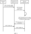
- FIG. 2 is a schematic flowchart of a data transmission method according to an embodiment of this application.
- a terminal device in this embodiment is in idle state. The method includes but is not limited to the following steps.
- Step S201 A first routing node receives downlink data of the terminal device, where the downlink data is determined and sent based on first routing information of the terminal device in a routing management node.
- the routing management node is a network device having a function of maintaining a routing table of the terminal device.
- the routing table of the terminal device includes routing information of the terminal device.
- the routing management node may determine a data transmission path based on the routing information of the terminal.
- the network device of the routing management node is not limited in this embodiment of this application.
- the routing management node may be an access network device having the function, or the routing management node may be a core network device (for example, a UPF) having the function.
- the terminal device is currently located in a coverage area of a first access network device, and a routing node corresponding to the first access network device is the first routing node.
- the first routing information of the terminal device may be ⁇ identifier information of the first routing node ⁇ ->identifier information of the first access network device ⁇ ->identifier information of the terminal device ⁇ .
- the routing management node may determine, based on a mapping relationship between the terminal device and the first routing node, to forward the downlink data to the first routing node.
- the downlink data of the terminal device received by the first routing node may be from the routing management node.
- another routing node or a data network may query the routing management node for the first routing information of the terminal device, and then send the downlink data to the first routing node based on the first routing information.
- Step S202 The first routing node sends a downlink paging request to a core network device.
- the downlink paging request is used to search for a second access network device corresponding to a current location of the terminal device.
- step S202a The first routing node sends a downlink paging request to the routing management node.
- the first routing node may send the downlink paging request to the routing management node, and then the second access network device sends a routing information update request to the routing management node.
- Step S203 The second access network device sends the routing information update request to the routing management node.
- the terminal device sends a paging request response message to the second access network device.
- the second access network device establishes a connection to a second routing node.
- the second access network device may send the routing information update request to the routing management node.
- Step S204 The routing management node determines second routing information of the terminal device based on the routing information update request, where the second routing information includes identifier information of the second routing node, identifier information of the second access network device, and the identifier information of the terminal device.
- the routing management node may determine the second routing information based on the routing information update request, where the second routing information may be ⁇ identifier information of the second routing node ⁇ ->identifier information of the second access network device ⁇ ->identifier information of the terminal device ⁇ .
- the routing management node may update the first routing information of the terminal device to the second routing information.
- Step S205 The routing management node sends the second routing information to the first routing node.
- Step S206 The first routing node sends, based on the second routing information, the downlink data to the terminal device via the second access network device.
- the first routing node may directly establish a connection to the second access network device, the first routing node may send the downlink data to the second access network device, and the second access network device sends the downlink data to the terminal device.
- the first routing node may send, based on the second routing information, the downlink data to the terminal device via the second routing node and the second access network device sequentially. For example, the first routing node may send the downlink data to the second routing node based on the second routing information, the second routing node sends the downlink data to the second access network device, and the second access network device sends the downlink data to the terminal device.
- This embodiment of this application may be applied to a core network architecture that includes a control plane core network (for example, an AMF) and a user plane core network (for example, a UPF), may be applied to a core network architecture that includes only a user plane core network, or may be applied to a network architecture in which the first routing node includes only an access network device. No specific limitation is imposed on this embodiment of this application.
- a control plane core network for example, an AMF
- a user plane core network for example, a UPF
- the downlink data arrives at a lowest-layer routing node of the terminal device, and the lowest-layer routing node triggers downlink paging.
- the second access network device pages the terminal device, data forwarding is supported.
- the second access network device may directly notify the user plane function node of location information of the terminal device, thereby reducing signaling overheads and a data transmission delay.
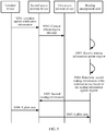
- FIG. 3 is a schematic flowchart of another data transmission method according to an embodiment of this application.
- a terminal device in this embodiment is in idle state. The method includes but is not limited to the following steps.
- Step S301 The terminal device sends location update notification information to a second access network device.
- a core network device or a radio access network may configure a valid mobility area for the terminal device. If the terminal device moves out of the valid mobility area, the terminal device needs to actively send the location update notification information to the second access network device. Alternatively, if the terminal device does not move out of the valid mobility area, when a periodic location update timer expires, the terminal device needs to actively send the location update notification information to the second access network device.
- the valid mobility area may include a tracking area list (tracking area list, TA list), a radio access network notification area (RAN Notification Area, RNA), or another mobility area.
- a tracking area list tracking area list, TA list
- a radio access network notification area RAN Notification Area, RNA
- Step S302 The second access network device sends a routing information update request to a routing management node.
- the second access network device may determine that the terminal device moves out of the valid mobility area, or may determine that the terminal device moves to an area covered by the second access network device, and then the second access network device may send the routing information update request to the routing management node.
- Step S303 The routing management node determines second routing information based on the routing information update request, where the second routing information includes identifier information of the second access network device and identifier information of the terminal device.
- the routing management node may determine the second routing information based on the routing information update request, where the second routing information may be ⁇ identifier information of the second access network device ⁇ ->identifier information of the terminal device ⁇ .
- the second routing information may further include identifier information of a second routing node.
- the second routing information may be ⁇ identifier information of the second routing node ⁇ ->identifier information of the second access network device ⁇ ->identifier information of the terminal device ⁇ .
- Step S304 The routing management node sends the second routing information to the second access network device.
- step S305 the terminal device sends uplink data to the second access network device.
- step S306 the second access network device sends the uplink data to the routing management node based on the second routing information.
- the second access network device may send the uplink data to the routing management node via the second routing node.
- the second routing information includes the identifier information of the second access network device, the identifier information of the second routing node, and the identifier information of the terminal device
- the second access network device may send the uplink data to the second routing node based on the second routing information, and the second routing node sends the uplink data to the routing management node.
- a lowest-layer routing node of the terminal device may directly notify a user plane function node of location information of the terminal device, so that the lowest-layer routing node is prevented from notifying the user plane function node of the location information of the terminal device via a control plane function node, thereby reducing signaling overheads and a data transmission delay.
- FIG. 4 is a schematic flowchart of another data transmission method according to an embodiment of this application.
- a terminal device in this embodiment is in inactive state. The method includes but is not limited to the following steps.
- Step S401 A first access network device receives downlink data of the terminal device, where the downlink data is determined and sent based on first routing information of the terminal device in a routing management node.
- the routing management node is a network device having a function of maintaining a routing table of the terminal device.
- the routing table of the terminal device includes routing information of the terminal device.
- the routing management node may determine a data transmission path based on the routing information of the terminal.
- the network device of the routing management node is not limited in this embodiment of this application.
- the routing management node may be an access network device having the function, or the routing management node may be a core network device (for example, a UPF) having the function.
- the terminal device is currently located in a coverage area of a first access network device.
- the first routing information of the terminal device may be ⁇ identifier information of the first access network device ⁇ ->identifier information of the terminal device ⁇ .
- the routing management node may determine, based on a mapping relationship between the terminal device and the first access network device, to forward the downlink data to the first access network device.
- the downlink data of the terminal device received by the first access network device may be from the routing management node.
- another routing node or a data network may query the routing management node for the first routing information of the terminal device, and then send the downlink data to the first access network device based on the first routing information.
- the first access network device may configure the terminal device to enter the inactive state, and the first access network device may also configure an RNA for the terminal device in inactive state.
- the third access network device may send a context obtain request message to the first access network device, and the first access network device may forward a context of the terminal device to the third access network device, or may reject to forward a context of the terminal device.
- the terminal device in inactive state moves out of the RNA, the terminal device in inactive state may send, to a new target access network device, a message used to indicate an RNA update.
- Step S402 The first access network device sends a downlink paging request to the third access network device.
- the first access network device may send a paging message to another access network device in the RNA of the terminal device, for example, send the downlink paging request to the third access network device, to page the terminal device via the first access network device and another access network device in the RNA of the terminal device.
- step S402a The first access network device sends a downlink paging request to the routing management node. For example, after the first access network device receives the downlink data of the terminal device, the first access network device sends the downlink paging request to the routing management node, and then the third access network device sends the context obtain request message to the first access network device.
- Step S403 The third access network device sends the context obtain request message to the first access network device.
- the terminal device moves to the area covered by the third access network device, after receiving the downlink paging request, the terminal device sends a paging request response message to the second access network device, and the third access network device may send the context obtain request message to the first access network device.
- the first access network device verifies the terminal device. When the verification succeeds, the first access network device may determine a current location of the terminal device as a location corresponding to the third access network device. Then, the first access network device sends the downlink data to the third access network device.
- Step S404 The first access network device sends the downlink data to the third access network device.
- Step S405 The third access network device sends the downlink data to the terminal device.
- the first access network device may send a routing information update request to the routing management node.
- the routing management node determines second routing information based on the routing information update request, where the second routing information may include identifier information of the third access network device and the identifier information of the terminal device.
- the first access network device when receiving the context obtain request message from the third access network device, may determine that the terminal device moves to the area covered by the third access network device, and then the first access network device requests the routing management node to update routing information, thereby reducing an update delay of the routing information.
- the third access network device may send the routing information update request to the routing management node. For example, if the third access network device receives, from the first access network device, a context of the terminal device or the downlink data of the terminal device, the third access network device may send the routing information update request to the routing management node.
- the routing management node determines second routing information based on the routing information update request, where the second routing information may include the identifier information of the third access network device and the identifier information of the terminal device.
- the third access network device requests the routing management node to update the routing information. This has higher robustness.
- the downlink data arrives at a lowest-layer routing node of the terminal device, and the lowest-layer routing node triggers downlink paging.
- the third access network device pages the terminal device, data forwarding is supported.
- the third access network device may directly notify the user plane function node of location information of the terminal device, thereby reducing signaling overheads and a data transmission delay.
- FIG. 5 is a schematic flowchart of another data transmission method according to an embodiment of this application.
- a terminal device in this embodiment is in inactive state. The method includes but is not limited to the following steps.
- Step S501 The terminal device sends location update notification information to a second access network device.
- step S301 For a mechanism for sending the location update notification information, refer to the descriptions in step S301. Details are not described herein again.
- Step S502 The second access network device sends a context obtain request message to a first access network device.
- Step S503 A routing management node receives a routing information update request.
- the first access network device may send the routing information update request to the routing management node.
- the second access network device may send the routing information update request to the routing management node. For example, after the second access network device sends the context obtain request message to the first access network device, if the second access network device receives a context of the terminal device from the first access network device, the second access network device may send the routing information update request to the routing management node.
- Step S504 The routing management node determines second routing information of the terminal device based on the routing information update request, where the second routing information includes identifier information of the second access network device and identifier information of the terminal device.
- the routing management node may determine the second routing information based on the routing information update request, where the second routing information may be ⁇ identifier information of the second access network device ⁇ ->identifier information of the terminal device ⁇ .
- Step S505 The routing management node sends the second routing information to the second access network device.
- step S506 the terminal device sends uplink data to the second access network device.
- the second access network device sends the uplink data to the routing management node based on the second routing information.
- a lowest-layer routing node of the terminal device may directly notify a user plane function node of location information of the terminal device, so that the lowest-layer routing node is prevented from notifying the user plane function node of the location information of the terminal device via a control plane function node, thereby reducing signaling overheads and a data transmission delay.
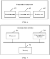
- FIG. 6 is a schematic structural diagram of a communication apparatus according to an embodiment of the present invention.
- the communication apparatus is configured to perform a step performed by the first routing node in the method embodiments corresponding to FIG. 2 to FIG. 5 .
- the communication apparatus may include:
- that the sending unit 602 sends, based on the second routing information, the downlink data to the terminal device via the second access network device includes: sending, based on the second routing information, the downlink data to the terminal device via the second routing node and the second access network device sequentially.
- FIG. 7 is a schematic structural diagram of another communication apparatus according to an embodiment of the present invention.
- the communication apparatus includes a processor 701, a memory 702, and a communication interface 703.
- the processor 701, the memory 702, and the communication interface 703 are connected by using one or more communication buses.
- the processor 701 is configured to support the communication apparatus in performing the methods in FIG. 2 to FIG. 5 .
- the processor 701 may be a central processing unit (central processing unit, CPU), a network processor (network processor, NP), a hardware chip, or any combination thereof.
- the memory 702 is configured to store program code and the like.
- the memory 702 may include a volatile memory (volatile memory), for example, a random access memory (random access memory, RAM).
- the memory 702 may alternatively include a non-volatile memory (non-volatile memory), for example, a read-only memory (read-only memory, ROM), a flash memory (flash memory), a hard disk drive (hard disk drive, HDD), or a solid-state drive (solid-state drive, SSD).
- the memory 702 may alternatively include a combination of the foregoing types of memories.
- the communication interface 703 is configured to receive and send data.
- the communication interface 703 is configured to transmit downlink data.
- the communication apparatus may include a plurality of communication interfaces, and a communication interface configured to send data and a communication interface configured to receive data may be different communication interfaces.
- the communication interface configured to send data is a transmitter
- the communication interface configured to receive data is a receiver.
- the processor 701 may invoke the program code stored in the memory 702 to perform the following operations:
- the processor 701 may specifically perform the following operation: sending, based on the second routing information, the downlink data to the terminal device via the second routing node and the second access network device sequentially.
- FIG. 6 is a schematic structural diagram of a communication apparatus according to an embodiment of the present invention.
- the communication apparatus is configured to perform a step performed by the first access network device in the method embodiments corresponding to FIG. 2 to FIG. 5 .
- the communication apparatus may include:
- the sending unit 602 may further send a routing information update request to the routing management node.
- the communication apparatus may further include a processing unit 603.
- the processing unit 603 is configured to: verify the terminal device, and when the verification succeeds, determine a current location of the terminal device as a location corresponding to the third access network device.
- FIG. 7 is a schematic structural diagram of another communication apparatus according to an embodiment of the present invention.
- the communication apparatus includes a processor 701, a memory 702, and a communication interface 703.
- the processor 701, the memory 702, and the communication interface 703 are connected by using one or more communication buses.
- the processor 701 may invoke program code stored in the memory 702, to perform the following operations:
- the processor 701 may further send a routing information update request to the routing management node.
- the processor 701 may further perform the following step: verifying the terminal device, and when the verification succeeds, determining a current location of the terminal device as a location corresponding to the third access network device.
- FIG. 6 is a schematic structural diagram of a communication apparatus according to an embodiment of the present invention.
- the communication apparatus is configured to perform a step performed by the second access network device in the method embodiments corresponding to FIG. 2 to FIG. 5 .
- the communication apparatus may include:
- the receiving unit 601 may further receive uplink data from the terminal device; and the sending unit 602 is further configured to send the uplink data to the routing management node based on the second routing information.
- the second routing information further includes a second routing node.
- the receiving unit 601 may further receive uplink data from the terminal device; and the sending unit 602 is further configured to send, based on the second routing information, the uplink data to the routing management node via the second routing node.
- that the sending unit 602 sends the routing information update request to the routing management node includes: sending a context obtain request message to a first access network device, where the routing information update request is sent by the first access network device to the routing management node.
- FIG. 7 is a schematic structural diagram of another communication apparatus according to an embodiment of the present invention.
- the communication apparatus includes a processor 701, a memory 702, and a communication interface 703.
- the processor 701, the memory 702, and the communication interface 703 are connected by using one or more communication buses.
- the processor 701 may invoke program code stored in the memory 702, to perform the following operations:
- the processor 701 may further perform the following operations:
- the second routing information further includes a second routing node.
- the processor 701 may further perform the following operations:
- the processor 701 may specifically perform the following operation: sending a context obtain request message to a first access network device, where the routing information update request is sent by the first access network device to the routing management node.
- All or some of the foregoing embodiments may be implemented by using software, hardware, firmware, or any combination thereof.
- all or some of the embodiments may be implemented in a form of a computer program product.
- the computer program product includes one or more computer instructions.
- the computer may be a general-purpose computer, a special-purpose computer, a computer network, or another programmable apparatus.
- the computer instructions may be stored in a computer-readable storage medium, or may be transmitted by using a computer-readable storage medium.
- the computer-readable storage medium may be any usable medium accessible by a computer, or a data storage device, such as a server integrating one or more usable media.
- the usable medium may be a magnetic medium, for example, a floppy disk, a hard disk, or a magnetic tape; or may be an optical medium, for example, a DVD; or may be a semiconductor medium, for example, a solid-state drive (solid state disk, SSD).
- a plurality of means two or more than two.
- the character "/" indicates a “division” relationship between associated objects.
Landscapes
- Engineering & Computer Science (AREA)
- Computer Networks & Wireless Communication (AREA)
- Signal Processing (AREA)
- Computer Security & Cryptography (AREA)
- Mobile Radio Communication Systems (AREA)
Abstract
Description
- This application claims priority to
Chinese Patent Application No. 201910135700.4, filed with the Chinese Patent Office on February 22, 2019 - This application relates to the field of communication technologies, and in particular, to a data transmission method, an apparatus, and a computer storage medium.
- In an existing data transmission architecture, data of a terminal device is transferred through a general packet radio service tunneling protocol (general packet radio service tunneling protocol, GTP) channel between an access network device and a fixed user plane function (user plane function, UPF) node. To be specific, after the terminal device accesses a network, a session management function (session management function, SMF) node selects a fixed UPF node for the terminal device, and establishes a fixed GTP channel: terminal device-first access network device-UPF-data network (data network, DN), where the SMF is a user plane function node. For data transmission based on the GTP channel, the GTP channel needs to be established first. When the terminal device moves to a coverage area of a second access network device, the SMF node removes a GTP channel of the terminal device between the first access network device and the UPF node, and establishes a GTP channel of the terminal device between the UPF and the second access network device. In the existing data transmission architecture, a location update procedure of the terminal device is as follows: The terminal device notifies an access and mobility management function (access and mobility management function, AMF) node, where the AMF is a control plane function node. The AMF node notifies the SMF node when there is a data service requirement. Then, the SMF node establishes a GTP channel, second access network device-UPF-DN, for the terminal device. Therefore, in the location update procedure, the terminal device needs to first notify the AMF, and then the AMF notifies the SMF. As a result, signaling overheads are relatively large, and a data transmission delay is relatively high.
- Embodiments of the present invention provide a data transmission method, an apparatus, and a computer storage medium. An access network device may directly notify a user plane function node of location information of a terminal device, and does not need to forward the location information of the terminal device via a control plane function node, thereby reducing signaling overheads and a data transmission delay.
- According to a first aspect, an embodiment of this application provides a data transmission method, including: A first routing node receives downlink data of a terminal device, where the downlink data is determined and sent based on first routing information of the terminal device in a routing management node. Then, the first routing node sends a downlink paging request to a core network device, where the downlink paging request is used to indicate the core network device to search for a second access network device corresponding to a current location of the terminal device. After the second access network device sends a routing information update request to the routing management node, the routing management node may determine second routing information based on the routing information update request, and send the second routing information to the first routing node, where the second routing information may include identifier information of a second routing node, identifier information of the second access network device, and identifier information of the terminal device. Based on this, the first routing node may send, based on the second routing information, the downlink data to the terminal device via the second access network device.
- In this technical solution, the downlink data arrives at a lowest-layer routing node of the terminal device, and the lowest-layer routing node triggers downlink paging. After the second access network device pages the terminal device, data forwarding is supported. The second access network device may directly notify a user plane function node of location information of the terminal device, thereby reducing signaling overheads and a data transmission delay.
- In a possible implementation, a manner in which the first routing node sends, based on the second routing information, the downlink data to the terminal device via the second access network device may be: sending the downlink data to the terminal device based on the second routing information via the second routing node and the second access network device sequentially.
- According to a second aspect, an embodiment of this application provides a data transmission method, including: A first access network device receives downlink data of a terminal device, where the downlink data is determined and sent based on first routing information of the terminal device in a routing management node. Then, the first access network device sends a downlink paging request to a third access network device, and the third access network device sends a context obtain request message to the first access network device. Based on this, the first access network device sends the downlink data to the terminal device via the third access network device.
- In this technical solution, the downlink data arrives at a lowest-layer routing node of the terminal device, and the lowest-layer routing node triggers downlink paging. After a second access network device pages the terminal device, data forwarding is supported. The second access network device may directly notify a user plane function node of location information of the terminal device, thereby reducing signaling overheads and a data transmission delay.
- In a possible implementation, before sending the downlink data to the terminal device via the third access network device, the first access network device may send a routing information update request to the routing management node.
- In a possible implementation, the first access network device may further verify the terminal device. When the verification succeeds, the first access network device determines a current location of the terminal device as a location corresponding to the third access network device.
- According to a third aspect, an embodiment of this application provides a data transmission method, including: A second access network device receives location update notification information sent by a terminal device, and the second access network device sends a routing information update request to a routing management node. The routing management node determines second routing information based on the routing information update request, and sends the second routing information to the second access network device, where the second routing information may include identifier information of the second access network device and identifier information of the terminal device.
- In this technical solution, a lowest-layer routing node of the terminal device may directly notify a user plane function node of location information of the terminal device, so that the lowest-layer routing node is prevented from notifying the user plane function node of the location information of the terminal device via a control plane function node, thereby reducing signaling overheads and a data transmission delay.
- In a possible implementation, after receiving the second routing information from the routing management node, the second access network device may receive uplink data from the terminal device, and the second network device sends the uplink data to the routing management node based on the second routing information.
- In a possible implementation, the second routing information may further include identifier information of the second routing node.
- In a possible implementation, after receiving the second routing information from the routing management node, the second access network device may receive uplink data from the terminal device, and the second access network device sends, based on the second routing information, the uplink data to the routing management node via the second routing node.
- In a possible implementation, a manner in which the second access network device sends the routing information update request to the routing management node may be: The second access network device sends a context obtain request message to a first access network device, where the routing information update request is sent by the first access network device to the routing management node.
- According to a fourth aspect, an embodiment of this application provides a communication apparatus. The apparatus includes units configured to implement the data transmission method in the first aspect to the third aspect.
- According to a fifth aspect, an embodiment of this application provides a computer storage medium. The computer storage medium stores a computer program or instructions. When the program or the instructions are executed by a processor, the processor is enabled to perform the data transmission method in the first aspect to the third aspect.
- According to a sixth aspect, an embodiment of this application provides a communication apparatus, including a processor, where the processor is coupled to a memory.
- The memory is configured to store instructions.
- The processor is configured to execute the instructions in the memory, to enable the communication apparatus to perform the method in the first aspect to the third aspect.
- According to a seventh aspect, an embodiment of this application provides a chip system, where the chip system includes a processor and an interface circuit, the interface circuit is coupled to the processor.
- The processor is configured to execute a computer program or instructions, to implement the method in the first aspect to the third aspect.
- The interface circuit is configured to communicate with another module outside the chip system.
-
-
FIG. 1 is a schematic structural diagram of a data transmission system according to an embodiment of this application; -
FIG. 2 is a schematic flowchart of a data transmission method according to an embodiment of this application; -
FIG. 3 is a schematic flowchart of another data transmission method according to an embodiment of this application; -
FIG. 4 is a schematic flowchart of another data transmission method according to an embodiment of this application; -
FIG. 5 is a schematic flowchart of another data transmission method according to an embodiment of this application; -
FIG. 6 is a schematic structural diagram of a communication apparatus according to an embodiment of this application; and -
FIG. 7 is a schematic structural diagram of another communication apparatus according to an embodiment of this application. - Embodiments of this application may be applied to a wireless communication system. The wireless communication system may be a new radio (new radio, NR) system in a 5th generation (5th generation, 5G) mobile communication system, or may be a future new wireless communication system. This is not limited in this application.
- In the embodiments of this application, an access network device, a terminal device, a routing node, a routing management node, and a core network device are specifically involved. The access network device is an access device used by the terminal device to access the wireless communication system in a wireless manner, and may be a NodeB (NodeB), an evolved NodeB (evolved NodeB, eNodeB), a transmission reception point (transmission reception point, TRP), a next generation NodeB (next generation NodeB, gNB) in the 5G mobile communication system, a base station in a future mobile communication system, an access node in a Wi-Fi system, or the like. A specific technology and a specific device form used for the access network device are not limited in the embodiments of this application.
- The terminal device may also be referred to as a terminal (Terminal), user equipment (user equipment, UE), a mobile station (mobile station, MS), a mobile terminal (mobile terminal, MT), or the like. The terminal device may be a mobile phone (mobile phone), a tablet (Pad), a computer having a wireless transceiver function, a virtual reality (virtual reality, VR) terminal device, an augmented reality (augmented reality, AR) terminal device, a wireless terminal in industrial control (industrial control), a wireless terminal in self driving (self driving), a wireless terminal in remote surgery (remote medical surgery), a wireless terminal in a smart grid (smart grid), a wireless terminal in transportation safety (transportation safety), a wireless terminal in a smart city (smart city), a wireless terminal in a smart home (smart home), or the like. A specific technology and a specific device form used for the terminal device are not limited in the embodiments of this application.
- The routing node may be a user plane function (user plane function, UPF) node or another node including an area corresponding to at least one routing. The UPF node is responsible for related functions of a user plane, including functions such as data flow identification and deep packet parsing, quality of service (quality of service, QoS) processing and bearer binding, and buffering of a downlink paging request.
- The routing management node (routing management node, RMN) is merely a function description, and may be a logical node or an entity node. For example, the RMN may be carried on an access network device or a user plane function node (for example, a UPF) including at least one access network device.
- The core network device may be an access and mobility management function (access and mobility management function, AMF) node.
- Data transmitted between the terminal device and the access network device may include uplink data and downlink data. The uplink data is data sent by the terminal device to the access network device, and the downlink data is data sent by the access network device to the terminal device.
- To better understand a data transmission method, an apparatus, and a computer storage medium that are disclosed in the embodiments of this application, the following first describes a data transmission system in the embodiments of this application.
FIG. 1 is a schematic structural diagram of a data transmission system according to an embodiment of this application. The data transmission system may include terminal devices, access network devices, routing nodes, and a DN. For example, the terminal devices may includeUE 1 andUE 2, the access network devices may include agNB 1 and agNB 2, and the routing nodes may include R1, R2, R3, R4, and R5. Compared with a conventional data transmission method, in this embodiment of this application, a GTP channel that is based on a terminal device and that is between an access network device and a routing node is not established, but a routing-based forwarding mechanism is used. As shown inFIG. 1 , a data forwarding channel routed to the DN is not fixed or based on the terminal device. Instead, a better routing path is flexibly selected based on an amount of data through each channel. For example, theUE 1 may send uplink data to the DN via thegNB 1, the R1, the R3, and the R4 sequentially. For another example, theUE 2 may send uplink data to the DN via thegNB 2, the R2, the R5, and the R3 sequentially. For another example, theUE 2 may send uplink data to the DN via thegNB 2, the R2, and the R4 sequentially. - A status of the terminal device may include an idle (idle) state, an inactive (inactive) state, and an active (active) state. The terminal device entering the idle state does not retain air interface configuration information. The air interface configuration information is, for example, an access stratum context of the terminal device. The inactive state is a state between the idle state and the active state. The terminal device in inactive state may retain the access stratum context of the terminal device, and an access network device that configures the terminal device to enter the inactive state also retains the access stratum context of the terminal device.
- The terminal device in different states may be routed to different layers in a routing table. For example, for the terminal device entering the idle state, a lowest-layer routing node in the routing table may be a UPF or another node including an area corresponding to at least one routing, such as a first routing node or a second routing node in the embodiments of this application. For another example, for the terminal device entering the inactive or active state, a lowest-layer routing node in the routing table may be an access network device, such as a first access network device, a second access network device, or a third access network device in the embodiments of this application.
- In the embodiments of this application, a routing-based forwarding mechanism is used, and data may be directly forwarded based on a routing table. Compared with a relatively slow conventional location update procedure in which the terminal device needs to first notify a control plane node AMF, and then the AMF notifies a user plane node SMF, in the embodiments of this application, location information of the terminal device may be directly notified to the user plane function node, thereby reducing signaling overheads and a data transmission delay.
- It may be understood that in the embodiments of this application, the terminal device and/or a network device may perform some or all steps in the embodiments of this application. These steps or operations are merely examples. In the embodiments of this application, other operations or variations of various operations may be further performed. In addition, the steps may be performed in a sequence different from a sequence presented in the embodiments of this application, and not all the operations in the embodiments of this application may be performed.
- With reference to the data transmission system shown in
FIG. 1 ,FIG. 2 is a schematic flowchart of a data transmission method according to an embodiment of this application. Optionally, a terminal device in this embodiment is in idle state. The method includes but is not limited to the following steps. - Step S201: A first routing node receives downlink data of the terminal device, where the downlink data is determined and sent based on first routing information of the terminal device in a routing management node.
- The routing management node is a network device having a function of maintaining a routing table of the terminal device. The routing table of the terminal device includes routing information of the terminal device. Optionally, the routing management node may determine a data transmission path based on the routing information of the terminal. The network device of the routing management node is not limited in this embodiment of this application. For example, the routing management node may be an access network device having the function, or the routing management node may be a core network device (for example, a UPF) having the function.
- For example, the terminal device is currently located in a coverage area of a first access network device, and a routing node corresponding to the first access network device is the first routing node. In this case, the first routing information of the terminal device may be {identifier information of the first routing node<->identifier information of the first access network device<->identifier information of the terminal device}. When the downlink data of the terminal device arrives, the routing management node may determine, based on a mapping relationship between the terminal device and the first routing node, to forward the downlink data to the first routing node.
- The downlink data of the terminal device received by the first routing node may be from the routing management node. Alternatively, another routing node or a data network may query the routing management node for the first routing information of the terminal device, and then send the downlink data to the first routing node based on the first routing information.
- Step S202: The first routing node sends a downlink paging request to a core network device.
- The downlink paging request is used to search for a second access network device corresponding to a current location of the terminal device.
- Alternatively, step S202a: The first routing node sends a downlink paging request to the routing management node. To be specific, after receiving the downlink data of the terminal device, the first routing node may send the downlink paging request to the routing management node, and then the second access network device sends a routing information update request to the routing management node.
- Step S203: The second access network device sends the routing information update request to the routing management node.
- For example, if the terminal device moves to an area covered by the second access network device, the terminal device sends a paging request response message to the second access network device. The second access network device establishes a connection to a second routing node. The second access network device may send the routing information update request to the routing management node.
- Step S204: The routing management node determines second routing information of the terminal device based on the routing information update request, where the second routing information includes identifier information of the second routing node, identifier information of the second access network device, and the identifier information of the terminal device.
- The routing management node may determine the second routing information based on the routing information update request, where the second routing information may be {identifier information of the second routing node<->identifier information of the second access network device<->identifier information of the terminal device}. The routing management node may update the first routing information of the terminal device to the second routing information.
- Step S205: The routing management node sends the second routing information to the first routing node.
- Step S206: The first routing node sends, based on the second routing information, the downlink data to the terminal device via the second access network device.
- In a specific implementation, if the first routing node may directly establish a connection to the second access network device, the first routing node may send the downlink data to the second access network device, and the second access network device sends the downlink data to the terminal device.
- In a possible implementation, the first routing node may send, based on the second routing information, the downlink data to the terminal device via the second routing node and the second access network device sequentially. For example, the first routing node may send the downlink data to the second routing node based on the second routing information, the second routing node sends the downlink data to the second access network device, and the second access network device sends the downlink data to the terminal device.
- This embodiment of this application may be applied to a core network architecture that includes a control plane core network (for example, an AMF) and a user plane core network (for example, a UPF), may be applied to a core network architecture that includes only a user plane core network, or may be applied to a network architecture in which the first routing node includes only an access network device. No specific limitation is imposed on this embodiment of this application.
- In this embodiment of this application, the downlink data arrives at a lowest-layer routing node of the terminal device, and the lowest-layer routing node triggers downlink paging. After the second access network device pages the terminal device, data forwarding is supported. The second access network device may directly notify the user plane function node of location information of the terminal device, thereby reducing signaling overheads and a data transmission delay.
- With reference to the data transmission system shown in
FIG. 1 ,FIG. 3 is a schematic flowchart of another data transmission method according to an embodiment of this application. Optionally, a terminal device in this embodiment is in idle state. The method includes but is not limited to the following steps. - Step S301: The terminal device sends location update notification information to a second access network device.
- In a specific implementation, a core network device or a radio access network (Radio Access Network, RAN) may configure a valid mobility area for the terminal device. If the terminal device moves out of the valid mobility area, the terminal device needs to actively send the location update notification information to the second access network device. Alternatively, if the terminal device does not move out of the valid mobility area, when a periodic location update timer expires, the terminal device needs to actively send the location update notification information to the second access network device.
- The valid mobility area may include a tracking area list (tracking area list, TA list), a radio access network notification area (RAN Notification Area, RNA), or another mobility area.
- Step S302: The second access network device sends a routing information update request to a routing management node.
- After receiving the location update notification information from the terminal device, the second access network device may determine that the terminal device moves out of the valid mobility area, or may determine that the terminal device moves to an area covered by the second access network device, and then the second access network device may send the routing information update request to the routing management node.
- Step S303: The routing management node determines second routing information based on the routing information update request, where the second routing information includes identifier information of the second access network device and identifier information of the terminal device.
- The routing management node may determine the second routing information based on the routing information update request, where the second routing information may be {identifier information of the second access network device<->identifier information of the terminal device}.
- In an implementation, the second routing information may further include identifier information of a second routing node. For example, the second routing information may be {identifier information of the second routing node<->identifier information of the second access network device<->identifier information of the terminal device}.
- Step S304: The routing management node sends the second routing information to the second access network device.
- Optionally, in step S305, the terminal device sends uplink data to the second access network device.
- Optionally, in step S306, the second access network device sends the uplink data to the routing management node based on the second routing information.
- In an implementation, the second access network device may send the uplink data to the routing management node via the second routing node. For example, if the second routing information includes the identifier information of the second access network device, the identifier information of the second routing node, and the identifier information of the terminal device, after receiving the uplink data from the terminal device, the second access network device may send the uplink data to the second routing node based on the second routing information, and the second routing node sends the uplink data to the routing management node.
- In this embodiment of this application, a lowest-layer routing node of the terminal device may directly notify a user plane function node of location information of the terminal device, so that the lowest-layer routing node is prevented from notifying the user plane function node of the location information of the terminal device via a control plane function node, thereby reducing signaling overheads and a data transmission delay.
- With reference to the data transmission system shown in
FIG. 1 ,FIG. 4 is a schematic flowchart of another data transmission method according to an embodiment of this application. Optionally, a terminal device in this embodiment is in inactive state. The method includes but is not limited to the following steps. - Step S401: A first access network device receives downlink data of the terminal device, where the downlink data is determined and sent based on first routing information of the terminal device in a routing management node.
- The routing management node is a network device having a function of maintaining a routing table of the terminal device. The routing table of the terminal device includes routing information of the terminal device. Optionally, the routing management node may determine a data transmission path based on the routing information of the terminal. The network device of the routing management node is not limited in this embodiment of this application. For example, the routing management node may be an access network device having the function, or the routing management node may be a core network device (for example, a UPF) having the function.
- For example, the terminal device is currently located in a coverage area of a first access network device. In this case, the first routing information of the terminal device may be {identifier information of the first access network device<->identifier information of the terminal device}. When the downlink data of the terminal device arrives, the routing management node may determine, based on a mapping relationship between the terminal device and the first access network device, to forward the downlink data to the first access network device.
- The downlink data of the terminal device received by the first access network device may be from the routing management node. Alternatively, another routing node or a data network may query the routing management node for the first routing information of the terminal device, and then send the downlink data to the first access network device based on the first routing information.
- For example, when the terminal device is in an area covered by the first access network device, the first access network device may configure the terminal device to enter the inactive state, and the first access network device may also configure an RNA for the terminal device in inactive state. When the terminal device in inactive state moves to an area that is covered by a third access network device and that is in the RNA, the third access network device may send a context obtain request message to the first access network device, and the first access network device may forward a context of the terminal device to the third access network device, or may reject to forward a context of the terminal device. When the terminal device in inactive state moves out of the RNA, the terminal device in inactive state may send, to a new target access network device, a message used to indicate an RNA update.
- Step S402: The first access network device sends a downlink paging request to the third access network device.
- For example, after the first access network device receives the downlink data of the terminal device, the first access network device may send a paging message to another access network device in the RNA of the terminal device, for example, send the downlink paging request to the third access network device, to page the terminal device via the first access network device and another access network device in the RNA of the terminal device.
- Alternatively, step S402a: The first access network device sends a downlink paging request to the routing management node. For example, after the first access network device receives the downlink data of the terminal device, the first access network device sends the downlink paging request to the routing management node, and then the third access network device sends the context obtain request message to the first access network device.
- Step S403: The third access network device sends the context obtain request message to the first access network device.
- If the terminal device moves to the area covered by the third access network device, after receiving the downlink paging request, the terminal device sends a paging request response message to the second access network device, and the third access network device may send the context obtain request message to the first access network device.
- In an implementation, after the third access network device sends the context obtain request message to the first access network device, the first access network device verifies the terminal device. When the verification succeeds, the first access network device may determine a current location of the terminal device as a location corresponding to the third access network device. Then, the first access network device sends the downlink data to the third access network device.
- Step S404: The first access network device sends the downlink data to the third access network device.
- Step S405: The third access network device sends the downlink data to the terminal device.
- In a possible implementation, after the first access network device receives the context obtain request message from the third access network device, the first access network device may send a routing information update request to the routing management node. The routing management node determines second routing information based on the routing information update request, where the second routing information may include identifier information of the third access network device and the identifier information of the terminal device.
- In this embodiment, when receiving the context obtain request message from the third access network device, the first access network device may determine that the terminal device moves to the area covered by the third access network device, and then the first access network device requests the routing management node to update routing information, thereby reducing an update delay of the routing information.
- In another possible implementation, the third access network device may send the routing information update request to the routing management node. For example, if the third access network device receives, from the first access network device, a context of the terminal device or the downlink data of the terminal device, the third access network device may send the routing information update request to the routing management node. The routing management node determines second routing information based on the routing information update request, where the second routing information may include the identifier information of the third access network device and the identifier information of the terminal device. In this embodiment, after obtaining a service, the third access network device requests the routing management node to update the routing information. This has higher robustness.
- In this embodiment of this application, the downlink data arrives at a lowest-layer routing node of the terminal device, and the lowest-layer routing node triggers downlink paging. After the third access network device pages the terminal device, data forwarding is supported. The third access network device may directly notify the user plane function node of location information of the terminal device, thereby reducing signaling overheads and a data transmission delay.
- With reference to the data transmission system shown in
FIG. 1 ,FIG. 5 is a schematic flowchart of another data transmission method according to an embodiment of this application. Optionally, a terminal device in this embodiment is in inactive state. The method includes but is not limited to the following steps. - Step S501: The terminal device sends location update notification information to a second access network device.
- For a mechanism for sending the location update notification information, refer to the descriptions in step S301. Details are not described herein again.
- Step S502: The second access network device sends a context obtain request message to a first access network device.
- Step S503: A routing management node receives a routing information update request.
- In a possible implementation, after receiving the context obtain request message from the second access network device, the first access network device may send the routing information update request to the routing management node.
- In another possible implementation, the second access network device may send the routing information update request to the routing management node. For example, after the second access network device sends the context obtain request message to the first access network device, if the second access network device receives a context of the terminal device from the first access network device, the second access network device may send the routing information update request to the routing management node.
- Step S504: The routing management node determines second routing information of the terminal device based on the routing information update request, where the second routing information includes identifier information of the second access network device and identifier information of the terminal device.
- The routing management node may determine the second routing information based on the routing information update request, where the second routing information may be {identifier information of the second access network device<->identifier information of the terminal device}.
- Step S505: The routing management node sends the second routing information to the second access network device.
- Optionally, in step S506, the terminal device sends uplink data to the second access network device.
- Optionally, in step S507, the second access network device sends the uplink data to the routing management node based on the second routing information.
- In this embodiment of this application, a lowest-layer routing node of the terminal device may directly notify a user plane function node of location information of the terminal device, so that the lowest-layer routing node is prevented from notifying the user plane function node of the location information of the terminal device via a control plane function node, thereby reducing signaling overheads and a data transmission delay.
- The foregoing describes in detail the methods in the embodiments of this application. The following provides related apparatuses in the embodiments of this application.
-
FIG. 6 is a schematic structural diagram of a communication apparatus according to an embodiment of the present invention. The communication apparatus is configured to perform a step performed by the first routing node in the method embodiments corresponding toFIG. 2 to FIG. 5 . The communication apparatus may include: - a receiving
unit 601, configured to receive downlink data of a terminal device, where the downlink data is determined and sent based on first routing information of the terminal device in a routing management node; and - a sending
unit 602, configured to send a downlink paging request to a core network device, where the downlink paging request is used to indicate the core network device to search for a second access network device corresponding to a current location of the terminal device, where - the receiving
unit 601 is further configured to receive second routing information from the routing management node, where the second routing information includes a second routing node, the second access network device, and the terminal device, and the second routing information is determined by the routing management node based on a routing information update request from the second access network device; and - the sending
unit 602 is further configured to send, based on the second routing information, the downlink data to the terminal device via the second access network device. - In a possible implementation, that the sending
unit 602 sends, based on the second routing information, the downlink data to the terminal device via the second access network device includes:
sending, based on the second routing information, the downlink data to the terminal device via the second routing node and the second access network device sequentially. - It should be noted that, for content that is not mentioned in the embodiment corresponding to
FIG. 6 and a specific implementation of steps performed by the units, refer to the embodiments shown inFIG. 2 to FIG. 5 and the foregoing content. Details are not described herein again. - In an implementation, related functions implemented by the units in
FIG. 6 may be implemented in combination with a processor and a communication interface.FIG. 7 is a schematic structural diagram of another communication apparatus according to an embodiment of the present invention. The communication apparatus includes aprocessor 701, amemory 702, and acommunication interface 703. Theprocessor 701, thememory 702, and thecommunication interface 703 are connected by using one or more communication buses. - The
processor 701 is configured to support the communication apparatus in performing the methods inFIG. 2 to FIG. 5 . Theprocessor 701 may be a central processing unit (central processing unit, CPU), a network processor (network processor, NP), a hardware chip, or any combination thereof. - The
memory 702 is configured to store program code and the like. Thememory 702 may include a volatile memory (volatile memory), for example, a random access memory (random access memory, RAM). Thememory 702 may alternatively include a non-volatile memory (non-volatile memory), for example, a read-only memory (read-only memory, ROM), a flash memory (flash memory), a hard disk drive (hard disk drive, HDD), or a solid-state drive (solid-state drive, SSD). Thememory 702 may alternatively include a combination of the foregoing types of memories. - The
communication interface 703 is configured to receive and send data. For example, thecommunication interface 703 is configured to transmit downlink data. - In this embodiment of the present invention, the communication apparatus may include a plurality of communication interfaces, and a communication interface configured to send data and a communication interface configured to receive data may be different communication interfaces. For example, the communication interface configured to send data is a transmitter, and the communication interface configured to receive data is a receiver.
- The
processor 701 may invoke the program code stored in thememory 702 to perform the following operations: - receiving downlink data of a terminal device by using the
communication interface 703, where the downlink data is determined and sent based on first routing information of the terminal device in a routing management node; - sending a downlink paging request to a core network device by using the
communication interface 703, where the downlink paging request is used to indicate the core network device to search for a second access network device corresponding to a current location of the terminal device; - receiving second routing information from the routing management node by using the
communication interface 703, where the second routing information includes a second routing node, the second access network device, and the terminal device, and the second routing information is determined by the routing management node based on a routing information update request from the second access network device; and - sending, by using the
communication interface 703 and based on the second routing information, the downlink data to the terminal device via the second access network device. - In an implementation, when the downlink data is sent to the terminal device via the second access network device by using the
communication interface 703 and based on the second routing information, theprocessor 701 may specifically perform the following operation:
sending, based on the second routing information, the downlink data to the terminal device via the second routing node and the second access network device sequentially. - It should be noted that, for content that is not mentioned in the embodiment corresponding to
FIG. 7 and a specific implementation of steps performed by the components, refer to the embodiments shown inFIG. 2 to FIG. 5 and the foregoing content. Details are not described herein again. -
FIG. 6 is a schematic structural diagram of a communication apparatus according to an embodiment of the present invention. The communication apparatus is configured to perform a step performed by the first access network device in the method embodiments corresponding toFIG. 2 to FIG. 5 . The communication apparatus may include: - a receiving
unit 601, configured to receive downlink data of a terminal device, where the downlink data is determined and sent based on first routing information of the terminal device in a routing management node; and - a sending
unit 602, configured to send a downlink paging request to a third access network device, where - the receiving
unit 601 is further configured to receive a context obtain request message from the third access network device; and - the sending
unit 602 is further configured to send the downlink data to the terminal device via the third access network device. - In an implementation, before sending the downlink data to the terminal device via the third access network device, the sending
unit 602 may further send a routing information update request to the routing management node. - In an implementation, the communication apparatus may further include a
processing unit 603. - The
processing unit 603 is configured to: verify the terminal device, and when the verification succeeds, determine a current location of the terminal device as a location corresponding to the third access network device. - It should be noted that, for content that is not mentioned in the embodiment corresponding to
FIG. 6 and a specific implementation of steps performed by the units, refer to the embodiments shown inFIG. 2 to FIG. 5 and the foregoing content. Details are not described herein again. - In an implementation, related functions implemented by the units in
FIG. 6 may be implemented in combination with a processor and a communication interface.FIG. 7 is a schematic structural diagram of another communication apparatus according to an embodiment of the present invention. The communication apparatus includes aprocessor 701, amemory 702, and acommunication interface 703. Theprocessor 701, thememory 702, and thecommunication interface 703 are connected by using one or more communication buses. - The
processor 701 may invoke program code stored in thememory 702, to perform the following operations: - receiving downlink data of a terminal device by using the
communication interface 703, where the downlink data is determined and sent based on first routing information of the terminal device in a routing management node; - sending a downlink paging request to a third access network device by using the
communication interface 703; - receiving, by using the
communication interface 703, a context obtain request message from the third access network device; and - sending, by using the
communication interface 703, the downlink data to the terminal device via the third access network device. - In an implementation, before the sending, by using the
communication interface 703, the downlink data to the terminal device via the third access network device, theprocessor 701 may further send a routing information update request to the routing management node. - In an implementation, the
processor 701 may further perform the following step:
verifying the terminal device, and when the verification succeeds, determining a current location of the terminal device as a location corresponding to the third access network device. - It should be noted that, for content that is not mentioned in the embodiment corresponding to
FIG. 7 and a specific implementation of steps performed by the components, refer to the embodiments shown inFIG. 2 to FIG. 5 and the foregoing content. Details are not described herein again. -
FIG. 6 is a schematic structural diagram of a communication apparatus according to an embodiment of the present invention. The communication apparatus is configured to perform a step performed by the second access network device in the method embodiments corresponding toFIG. 2 to FIG. 5 . The communication apparatus may include: - a receiving
unit 601, configured to receive location update notification information sent by a terminal device; and - a sending
unit 602, configured to send a routing information update request to a routing management node, where - the receiving
unit 601 is further configured to receive second routing information from the routing management node, where the second routing information includes the second access network device and the terminal device. - In an implementation, after receiving the second routing information from the routing management node, the receiving
unit 601 may further receive uplink data from the terminal device; and
the sendingunit 602 is further configured to send the uplink data to the routing management node based on the second routing information. - In an implementation, the second routing information further includes a second routing node.
- In an implementation, after receiving the second routing information from the routing management node, the receiving
unit 601 may further receive uplink data from the terminal device; and
the sendingunit 602 is further configured to send, based on the second routing information, the uplink data to the routing management node via the second routing node. - In an implementation, that the sending
unit 602 sends the routing information update request to the routing management node includes:
sending a context obtain request message to a first access network device, where the routing information update request is sent by the first access network device to the routing management node. - It should be noted that, for content that is not mentioned in the embodiment corresponding to
FIG. 6 and a specific implementation of steps performed by the units, refer to the embodiments shown inFIG. 2 to FIG. 5 and the foregoing content. Details are not described herein again. - In an implementation, related functions implemented by the units in
FIG. 6 may be implemented in combination with a processor and a communication interface.FIG. 7 is a schematic structural diagram of another communication apparatus according to an embodiment of the present invention. The communication apparatus includes aprocessor 701, amemory 702, and acommunication interface 703. Theprocessor 701, thememory 702, and thecommunication interface 703 are connected by using one or more communication buses. - The
processor 701 may invoke program code stored in thememory 702, to perform the following operations: - receiving, by using the
communication interface 703, location update notification information sent by a terminal device; - sending a routing information update request to a routing management node by using the
communication interface 703; and - receiving second routing information from the routing management node by using the
communication interface 703, where the second routing information includes the second access network device and the terminal device. - In an implementation, after receiving the second routing information from the routing management node by using the
communication interface 703, theprocessor 701 may further perform the following operations: - receiving uplink data from the terminal device; and
- sending the uplink data to the routing management node based on the second routing information.
- In an implementation, the second routing information further includes a second routing node.
- In an implementation, after receiving the second routing information from the routing management node by using the
communication interface 703, theprocessor 701 may further perform the following operations: - receiving uplink data from the terminal device; and
- sending, based on the second routing information, the uplink data to the routing management node via the second routing node.
- In an implementation, when sending the routing information update request to the routing management node by using the
communication interface 703, theprocessor 701 may specifically perform the following operation:
sending a context obtain request message to a first access network device, where the routing information update request is sent by the first access network device to the routing management node. - It should be noted that, for content that is not mentioned in the embodiment corresponding to
FIG. 7 and a specific implementation of steps performed by the components, refer to the embodiments shown inFIG. 2 to FIG. 5 and the foregoing content. Details are not described herein again. - All or some of the foregoing embodiments may be implemented by using software, hardware, firmware, or any combination thereof. When being implemented by using the software, all or some of the embodiments may be implemented in a form of a computer program product. The computer program product includes one or more computer instructions. When the computer program instructions are loaded and executed on a computer, the procedures or functions according to the embodiments of this application are all or partially generated. The computer may be a general-purpose computer, a special-purpose computer, a computer network, or another programmable apparatus. The computer instructions may be stored in a computer-readable storage medium, or may be transmitted by using a computer-readable storage medium. The computer-readable storage medium may be any usable medium accessible by a computer, or a data storage device, such as a server integrating one or more usable media. The usable medium may be a magnetic medium, for example, a floppy disk, a hard disk, or a magnetic tape; or may be an optical medium, for example, a DVD; or may be a semiconductor medium, for example, a solid-state drive (solid state disk, SSD).
- In the embodiments of this application, unless otherwise specified or there is a logic conflict, terms and descriptions between different embodiments are consistent and may be mutually referenced, and technical features in different embodiments may be combined based on an internal logical relationship thereof, to form a new embodiment.
- In this application, "a plurality of" means two or more than two. In the formula of this application, the character "/" indicates a "division" relationship between associated objects.
- It may be understood that various numbers in the embodiments of this application are merely used for differentiation for ease of description, and are not used to limit the scope of the embodiments of this application. Sequence numbers of the foregoing processes do not mean execution sequences. The execution sequences of the processes should be determined based on functions and internal logic of the processes.
Claims (15)
- A data transmission method, comprising:receiving, by a first routing node, downlink data of a terminal device, wherein the downlink data is determined and sent based on first routing information of the terminal device in a routing management node;sending, by the first routing node, a downlink paging request to a core network device, wherein the downlink paging request is used to indicate the core network device to search for a second access network device corresponding to a current location of the terminal device;receiving, by the first routing node, second routing information from the routing management node, wherein the second routing information comprises identifier information of a second routing node, identifier information of the second access network device, and identifier information of the terminal device, and the second routing information is determined by the routing management node based on a routing information update request from the second access network device; andsending, by the first routing node based on the second routing information, the downlink data to the terminal device via the second access network device.
- The method according to claim 1, wherein the sending, by the first routing node based on the second routing information, the downlink data to the terminal device via the second access network device comprises:
sending, by the first routing node based on the second routing information, the downlink data to the terminal device via the second routing node and the second access network device sequentially. - A data transmission method, comprising:receiving, by a first access network device, downlink data of a terminal device, wherein the downlink data is determined and sent based on first routing information of the terminal device in a routing management node;sending, by the first access network device, a downlink paging request to a third access network device;receiving, by the first access network device, a context obtain request message from the third access network device; andsending, by the first access network device, the downlink data to the terminal device via the third access network device.
- The method according to claim 3, wherein before the sending, by the first access network device, the downlink data to the terminal device via the third access network device, the method further comprises:
sending, by the first access network device, a routing information update request to the routing management node. - The method according to claim 3 or 4, wherein the method further comprises:verifying, by the first access network device, the terminal device; andwhen the verification succeeds, determining, by the first access network device, a current location of the terminal device as a location corresponding to the third access network device.
- A data transmission method, comprising:receiving, by a second access network device, location update notification information sent by a terminal device;sending, by the second access network device, a routing information update request to a routing management node; andreceiving, by the second access network device, second routing information from the routing management node, wherein the second routing information comprises identifier information of the second access network device and identifier information of the terminal device.
- The method according to claim 6, wherein after the receiving, by the second access network device, second routing information from the routing management node, the method further comprises:receiving, by the second access network device, uplink data from the terminal device; andsending, by the second access network device, the uplink data to the routing management node based on the second routing information.
- The method according to claim 6, wherein the second routing information further comprises identifier information of a second routing node.
- The method according to claim 8, wherein after the receiving, by the second access network device, second routing information from the routing management node, the method further comprises:receiving, by the second access network device, uplink data from the terminal device; andsending, by the second access network device based on the second routing information, the uplink data to the routing management node via the second routing node.
- The method according to claim 6, wherein the sending, by the second access network device, a routing information update request to a routing management node comprises:
sending, by the second access network device, a context obtain request message to a first access network device, wherein the routing information update request is sent by the first access network device to the routing management node. - A communication apparatus, comprising units configured to implement the data transmission method according to claim 1 or 2.
- A communication apparatus, comprising units configured to implement the data transmission method according to any one of claims 3 to 5.
- A communication apparatus, comprising units configured to implement the data transmission method according to any one of claims 6 to 10.
- A computer storage medium, storing a computer program or instructions, wherein when the program or the instructions are executed by a processor, the processor is enabled to perform the data transmission method according to any one of claims 1 to 10.
- A communication system, comprising the communication apparatus according to claim 11, the communication apparatus according to claim 12, and the communication apparatus according to claim 13.
Applications Claiming Priority (2)
| Application Number | Priority Date | Filing Date | Title |
|---|---|---|---|
| CN201910135700.4A CN111615188B (en) | 2019-02-22 | 2019-02-22 | Data transmission method, device and computer storage medium |
| PCT/CN2020/076030 WO2020169068A1 (en) | 2019-02-22 | 2020-02-20 | Data transmission method and apparatus, and computer storage medium |
Publications (3)
| Publication Number | Publication Date |
|---|---|
| EP3917230A1 true EP3917230A1 (en) | 2021-12-01 |
| EP3917230A4 EP3917230A4 (en) | 2022-08-24 |
| EP3917230B1 EP3917230B1 (en) | 2026-01-14 |
Family
ID=72143317
Family Applications (1)
| Application Number | Title | Priority Date | Filing Date |
|---|---|---|---|
| EP20759011.8A Active EP3917230B1 (en) | 2019-02-22 | 2020-02-20 | Data transmission method and apparatus, and computer storage medium |
Country Status (5)
| Country | Link |
|---|---|
| US (1) | US12052646B2 (en) |
| EP (1) | EP3917230B1 (en) |
| JP (1) | JP7266695B2 (en) |
| CN (1) | CN111615188B (en) |
| WO (1) | WO2020169068A1 (en) |
Families Citing this family (2)
| Publication number | Priority date | Publication date | Assignee | Title |
|---|---|---|---|---|
| CN114666862B (en) * | 2022-03-25 | 2025-03-04 | Oppo广东移动通信有限公司 | Data routing method and device |
| CN114786121B (en) * | 2022-04-07 | 2024-06-11 | 中国联合网络通信集团有限公司 | Positioning method, device, system and storage medium |
Family Cites Families (54)
| Publication number | Priority date | Publication date | Assignee | Title |
|---|---|---|---|---|
| US6845095B2 (en) * | 2001-04-27 | 2005-01-18 | Telefonaktiebolaget Lm Ericsson (Publ) | Efficient header handling involving GSM/EDGE radio access networks |
| KR100744374B1 (en) * | 2005-07-15 | 2007-07-30 | 삼성전자주식회사 | Handover Method and Device Between Core Network Entities in Packet-switched Networks |
| EP1784035A1 (en) * | 2005-11-07 | 2007-05-09 | Alcatel Lucent | A method for connection re-establishment in a mobile communication system |
| AR065302A1 (en) * | 2007-02-12 | 2009-05-27 | Interdigital Patent Holdings | METHOD AND APPLIANCE TO SUPPORT TRANSFER FROM LTE / EUTRAN TO GPRS / GERAN |
| CN101370266B (en) * | 2007-08-19 | 2013-03-20 | 华为技术有限公司 | Switching method and terminal re-adhesion method |
| WO2009070061A1 (en) * | 2007-11-30 | 2009-06-04 | Telefonaktiebolaget L M Ericson (Publ) | Method and apparatus for handling a local breakout session |
| US8520596B2 (en) * | 2007-12-19 | 2013-08-27 | Telefonaktiebolaget L M Ericsson (Publ) | Inter-domain coordination for MT and MO calls |
| WO2009088331A1 (en) * | 2008-01-10 | 2009-07-16 | Telefonaktiebolaget Lm Ericsson (Publ) | Improved method and arrangement in a telecommunications system |
| US20110070886A1 (en) * | 2008-02-18 | 2011-03-24 | Ntt Docomo, Inc. | Mobile communication system, location registration method, handover method, exchange, mobile station, and radio control station |
| US8145195B2 (en) * | 2008-04-14 | 2012-03-27 | Nokia Corporation | Mobility related control signalling authentication in mobile communications system |
| US10893556B2 (en) * | 2009-04-30 | 2021-01-12 | Samsung Electronics Co., Ltd | Method and apparatus for supporting local IP access in a femto cell of a wireless communication system |
| CN101674628A (en) * | 2009-09-30 | 2010-03-17 | 中兴通讯股份有限公司 | Route reselection method and wireless network controller |
| CN102143539B (en) * | 2010-02-02 | 2015-04-01 | 中兴通讯股份有限公司 | Method and system for acquiring context of terminal |
| CN102076054A (en) * | 2011-02-18 | 2011-05-25 | 电信科学技术研究院 | Direct forwarding tunnel setup and using method, system and equipment |
| CN102740268B (en) * | 2011-04-07 | 2017-04-12 | 中兴通讯股份有限公司 | System for packet data network gateway and terminal mobility management |
| EP2557890B1 (en) * | 2011-08-12 | 2019-07-17 | BlackBerry Limited | Simplified ue + enb messaging |
| CN103108300B (en) * | 2011-11-10 | 2018-01-30 | 中兴通讯股份有限公司 | Location updating method and mobile router access service router |
| EP3122149B1 (en) * | 2012-09-28 | 2025-06-11 | Apple Inc. | Always-on bearer for small data transfers in lte systems |
| WO2015085273A1 (en) * | 2013-12-06 | 2015-06-11 | Interdigital Patent Holdings, Inc. | Layered connectivity in wireless systems |
| WO2016018183A1 (en) * | 2014-07-31 | 2016-02-04 | Telefonaktiebolaget L M Ericsson (Publ) | Routing of mptcp subflows |
| CN108370506B (en) * | 2015-11-04 | 2021-07-13 | Lg 电子株式会社 | Service node relocation method and device in wireless communication system |
| CN106686622A (en) * | 2015-11-09 | 2017-05-17 | 中兴通讯股份有限公司 | Method and device for updating information of gateway |
| EP3403429B1 (en) * | 2016-01-14 | 2020-04-22 | Telefonaktiebolaget LM Ericsson (PUBL) | Method and nodes for performing a tracking area update (tau) / routing area update (rau) procedure in a stateless architecture |
| WO2017188787A2 (en) * | 2016-04-29 | 2017-11-02 | 엘지전자 주식회사 | Data transmission method performed by base station in wireless communication system, and apparatus using same |
| CN107360565B (en) | 2016-05-09 | 2020-01-07 | 中国移动通信有限公司研究院 | Gateway switching method, control plane network element, gateway, base station and network architecture |
| JP2019515593A (en) * | 2016-05-10 | 2019-06-06 | 華為技術有限公司Huawei Technologies Co.,Ltd. | Mobility management method and apparatus |
| JP6654240B2 (en) | 2016-07-08 | 2020-02-26 | 株式会社Nttドコモ | Wireless communication system and communication method |
| CN108307499B (en) * | 2016-08-12 | 2019-07-19 | 电信科学技术研究院 | Paging receives paging, paging control method and device |
| CN108377522B (en) * | 2016-11-03 | 2020-02-07 | 电信科学技术研究院 | Information forwarding method and base station |
| US10728952B2 (en) * | 2017-01-09 | 2020-07-28 | Huawei Technologies Co., Ltd. | System and methods for session management |
| CN108632953A (en) * | 2017-02-10 | 2018-10-09 | 中兴通讯股份有限公司 | A kind of method and device for realizing multiple access management |
| JP6871427B2 (en) | 2017-02-15 | 2021-05-12 | 華為技術有限公司Huawei Technologies Co.,Ltd. | Data transmission methods, base stations, local breakout controllers, gateways, and systems |
| US10264622B2 (en) * | 2017-03-17 | 2019-04-16 | Ofinno Technologies, Llc | Inactive state data forwarding |
| CN108632915B (en) * | 2017-03-20 | 2022-07-15 | 中兴通讯股份有限公司 | A method, device and device for terminal moving between 4G and 5G networks |
| KR102289879B1 (en) * | 2017-03-20 | 2021-08-13 | 삼성전자 주식회사 | UPF Relocation for PDU Session of Various SSC Modes in Cellular Networks |
| US10779345B2 (en) * | 2017-03-20 | 2020-09-15 | Qualcomm Incorporated | User plane relocation techniques in wireless communication systems |
| US11083028B2 (en) * | 2017-03-31 | 2021-08-03 | Telefonaktiebolaget Lm Ericsson (Publ) | Coordinated selection of user plane functions in core and radio access networks |
| CN108738086B (en) * | 2017-04-21 | 2020-08-07 | 华为技术有限公司 | Method and device for user plane reselection |
| CN108881356B (en) * | 2017-05-11 | 2023-10-24 | 华为技术有限公司 | Methods for caching data and session management function devices |
| CN110771251B (en) * | 2017-06-16 | 2023-09-22 | 艾普拉控股有限公司 | Small data transfer, data buffering and data management as services in a communication network |
| EP3643116B1 (en) | 2017-06-19 | 2022-05-11 | IDAC Holdings, Inc. | User plane relocation |
| CN109104746B (en) | 2017-06-20 | 2021-01-15 | 华为技术有限公司 | Communication method and device |
| KR102364802B1 (en) | 2017-06-23 | 2022-02-17 | 후아웨이 테크놀러지 컴퍼니 리미티드 | Service continuity implementation method, device and service continuity implementation system |
| US20190007992A1 (en) * | 2017-07-03 | 2019-01-03 | Electronics And Telecommunications Research Institute | Network triggered service request method and user equipment (ue) triggered service request method |
| US11128985B2 (en) * | 2017-08-14 | 2021-09-21 | Qualcomm Incorporated | Systems and methods for 5G location support using service based interfaces |
| WO2019033281A1 (en) * | 2017-08-15 | 2019-02-21 | Zte Corporation | Methods and computing device for changing a user plane function |
| US10779254B2 (en) * | 2017-08-16 | 2020-09-15 | Electronics And Telecommunications Research Institute | Service request method for 5G local service |
| WO2019067971A1 (en) * | 2017-09-28 | 2019-04-04 | Ofinno Technologies, Llc | Smf, amf and upf relocation during ue registration |
| US10834636B2 (en) * | 2018-01-10 | 2020-11-10 | Ofinno, Llc | Discovery and selection of UPF for uplink classifier |
| WO2019160300A1 (en) * | 2018-02-19 | 2019-08-22 | 엘지전자 주식회사 | Method for transmitting sm signal to terminal capable of connecting to plurality of network systems |
| CN110536378A (en) * | 2018-05-23 | 2019-12-03 | 北京三星通信技术研究有限公司 | A method, device and storage medium for sending data |
| EP4593463A3 (en) * | 2018-06-19 | 2025-10-22 | Telefonaktiebolaget LM Ericsson (publ) | Methods providing anchor change for ethernet pou sessions and related network entities/nodes |
| US11224093B2 (en) * | 2018-08-13 | 2022-01-11 | Ofinno, Llc | Network initiated UPF sessions transfer |
| US11129215B2 (en) * | 2019-02-15 | 2021-09-21 | Ofinno, Llc | Location based selection of localized proxy application server |
-
2019
- 2019-02-22 CN CN201910135700.4A patent/CN111615188B/en active Active
-
2020
- 2020-02-20 WO PCT/CN2020/076030 patent/WO2020169068A1/en not_active Ceased
- 2020-02-20 JP JP2021549393A patent/JP7266695B2/en active Active
- 2020-02-20 EP EP20759011.8A patent/EP3917230B1/en active Active
-
2021
- 2021-08-20 US US17/408,192 patent/US12052646B2/en active Active
Also Published As
| Publication number | Publication date |
|---|---|
| CN111615188A (en) | 2020-09-01 |
| JP7266695B2 (en) | 2023-04-28 |
| CN111615188B (en) | 2021-10-01 |
| WO2020169068A1 (en) | 2020-08-27 |
| US20210385725A1 (en) | 2021-12-09 |
| EP3917230B1 (en) | 2026-01-14 |
| US12052646B2 (en) | 2024-07-30 |
| JP2022521538A (en) | 2022-04-08 |
| EP3917230A4 (en) | 2022-08-24 |
Similar Documents
| Publication | Publication Date | Title |
|---|---|---|
| EP3761679B1 (en) | Location method and related device | |
| US10420009B2 (en) | Methods and devices for determining and using Device-to-Device relay node | |
| EP3606281B1 (en) | Paging method, paging apparatus and terminal device | |
| EP3641363A1 (en) | Method for inserting smf and amf entity | |
| EP4191951A1 (en) | Session processing method, apparatus, and system | |
| US12563616B2 (en) | Packet forwarding method, apparatus, and system | |
| KR20190010884A (en) | Wireless communication method and apparatus | |
| US10681590B2 (en) | Method and apparatus for handover procedures in a communication network | |
| TW201831002A (en) | Device and Method for Handling New Radio Capacities | |
| CN111385830A (en) | Communication method and device | |
| US11864149B2 (en) | Systems and methods for user equipment (UE) registration | |
| EP3681182B1 (en) | Method, apparatus and device for determining state of terminal device | |
| CN113273232A (en) | Method for processing terminal capability in wireless communication network | |
| JP2021528007A (en) | Communication method and communication device | |
| JP7751071B2 (en) | User terminal access method, device, user terminal, and storage medium | |
| US12052646B2 (en) | Data transmission method, apparatus, and computer storage medium | |
| JP2019534636A (en) | Session management method and session management network element | |
| US20180084462A1 (en) | User Equipment Handover Method and Device | |
| CN105264966B (en) | A kind of identification interaction method and device | |
| CN108924959B (en) | Method of wireless communication, AMF and RAN | |
| US20200128603A1 (en) | Method for acquiring context configuration information, terminal device and access network device | |
| US11622403B2 (en) | Data sending method, apparatus, and system | |
| US20240056950A1 (en) | Communication method and apparatus | |
| JP2026510748A (en) | Communication methods and devices | |
| JP2023500097A (en) | Communication method, device and communication system for vehicle communication service |
Legal Events
| Date | Code | Title | Description |
|---|---|---|---|
| STAA | Information on the status of an ep patent application or granted ep patent |
Free format text: STATUS: THE INTERNATIONAL PUBLICATION HAS BEEN MADE |
|
| PUAI | Public reference made under article 153(3) epc to a published international application that has entered the european phase |
Free format text: ORIGINAL CODE: 0009012 |
|
| STAA | Information on the status of an ep patent application or granted ep patent |
Free format text: STATUS: REQUEST FOR EXAMINATION WAS MADE |
|
| 17P | Request for examination filed |
Effective date: 20210826 |
|
| AK | Designated contracting states |
Kind code of ref document: A1 Designated state(s): AL AT BE BG CH CY CZ DE DK EE ES FI FR GB GR HR HU IE IS IT LI LT LU LV MC MK MT NL NO PL PT RO RS SE SI SK SM TR |
|
| RIC1 | Information provided on ipc code assigned before grant |
Ipc: H04W 48/18 20090101ALI20220221BHEP Ipc: H04W 36/12 20090101AFI20220221BHEP |
|
| DAV | Request for validation of the european patent (deleted) | ||
| DAX | Request for extension of the european patent (deleted) | ||
| REG | Reference to a national code |
Ref country code: DE Free format text: PREVIOUS MAIN CLASS: H04W0068020000 Ipc: H04W0036120000 Ref country code: DE Ref legal event code: R079 Ref document number: 602020065518 Country of ref document: DE Free format text: PREVIOUS MAIN CLASS: H04W0068020000 Ipc: H04W0036120000 |
|
| A4 | Supplementary search report drawn up and despatched |
Effective date: 20220721 |
|
| RIC1 | Information provided on ipc code assigned before grant |
Ipc: H04W 40/38 20090101ALN20220715BHEP Ipc: H04L 45/02 20220101ALN20220715BHEP Ipc: H04W 68/00 20090101ALN20220715BHEP Ipc: H04W 40/24 20090101ALI20220715BHEP Ipc: H04W 40/20 20090101ALI20220715BHEP Ipc: H04W 48/18 20090101ALI20220715BHEP Ipc: H04W 36/12 20090101AFI20220715BHEP |
|
| STAA | Information on the status of an ep patent application or granted ep patent |
Free format text: STATUS: EXAMINATION IS IN PROGRESS |
|
| 17Q | First examination report despatched |
Effective date: 20240408 |
|
| GRAP | Despatch of communication of intention to grant a patent |
Free format text: ORIGINAL CODE: EPIDOSNIGR1 |
|
| STAA | Information on the status of an ep patent application or granted ep patent |
Free format text: STATUS: GRANT OF PATENT IS INTENDED |
|
| RIC1 | Information provided on ipc code assigned before grant |
Ipc: H04W 36/12 20090101AFI20250910BHEP Ipc: H04W 48/18 20090101ALI20250910BHEP Ipc: H04W 40/20 20090101ALI20250910BHEP Ipc: H04W 40/24 20090101ALI20250910BHEP Ipc: H04W 68/00 20090101ALN20250910BHEP Ipc: H04L 45/02 20220101ALN20250910BHEP Ipc: H04W 40/38 20090101ALN20250910BHEP Ipc: H04L 45/00 20220101ALN20250910BHEP |
|
| INTG | Intention to grant announced |
Effective date: 20250925 |
|
| GRAS | Grant fee paid |
Free format text: ORIGINAL CODE: EPIDOSNIGR3 |
|
| GRAA | (expected) grant |
Free format text: ORIGINAL CODE: 0009210 |
|
| STAA | Information on the status of an ep patent application or granted ep patent |
Free format text: STATUS: THE PATENT HAS BEEN GRANTED |
|
| AK | Designated contracting states |
Kind code of ref document: B1 Designated state(s): AL AT BE BG CH CY CZ DE DK EE ES FI FR GB GR HR HU IE IS IT LI LT LU LV MC MK MT NL NO PL PT RO RS SE SI SK SM TR |
|
| REG | Reference to a national code |
Ref country code: CH Ref legal event code: F10 Free format text: ST27 STATUS EVENT CODE: U-0-0-F10-F00 (AS PROVIDED BY THE NATIONAL OFFICE) Effective date: 20260114 Ref country code: GB Ref legal event code: FG4D |
|
| REG | Reference to a national code |
Ref country code: DE Ref legal event code: R096 Ref document number: 602020065518 Country of ref document: DE |
|
| REG | Reference to a national code |
Ref country code: IE Ref legal event code: FG4D |
|
| PGFP | Annual fee paid to national office [announced via postgrant information from national office to epo] |
Ref country code: DE Payment date: 20260114 Year of fee payment: 7 |