EP3917001A1 - An electric machine - Google Patents
An electric machine Download PDFInfo
- Publication number
- EP3917001A1 EP3917001A1 EP21176436.0A EP21176436A EP3917001A1 EP 3917001 A1 EP3917001 A1 EP 3917001A1 EP 21176436 A EP21176436 A EP 21176436A EP 3917001 A1 EP3917001 A1 EP 3917001A1
- Authority
- EP
- European Patent Office
- Prior art keywords
- current
- electric motor
- electric machine
- sensors
- power
- Prior art date
- Legal status (The legal status is an assumption and is not a legal conclusion. Google has not performed a legal analysis and makes no representation as to the accuracy of the status listed.)
- Granted
Links
Images

Classifications
-
- H—ELECTRICITY
- H02—GENERATION; CONVERSION OR DISTRIBUTION OF ELECTRIC POWER
- H02P—CONTROL OR REGULATION OF ELECTRIC MOTORS, ELECTRIC GENERATORS OR DYNAMO-ELECTRIC CONVERTERS; CONTROLLING TRANSFORMERS, REACTORS OR CHOKE COILS
- H02P29/00—Arrangements for regulating or controlling electric motors, appropriate for both AC and DC motors
- H02P29/02—Providing protection against overload without automatic interruption of supply
- H02P29/024—Detecting a fault condition, e.g. short circuit, locked rotor, open circuit or loss of load
-
- H—ELECTRICITY
- H02—GENERATION; CONVERSION OR DISTRIBUTION OF ELECTRIC POWER
- H02P—CONTROL OR REGULATION OF ELECTRIC MOTORS, ELECTRIC GENERATORS OR DYNAMO-ELECTRIC CONVERTERS; CONTROLLING TRANSFORMERS, REACTORS OR CHOKE COILS
- H02P27/00—Arrangements or methods for the control of AC motors characterised by the kind of supply voltage
- H02P27/04—Arrangements or methods for the control of AC motors characterised by the kind of supply voltage using variable-frequency supply voltage, e.g. inverter or converter supply voltage
- H02P27/06—Arrangements or methods for the control of AC motors characterised by the kind of supply voltage using variable-frequency supply voltage, e.g. inverter or converter supply voltage using DC to AC converters or inverters
-
- H—ELECTRICITY
- H02—GENERATION; CONVERSION OR DISTRIBUTION OF ELECTRIC POWER
- H02H—EMERGENCY PROTECTIVE CIRCUIT ARRANGEMENTS
- H02H7/00—Emergency protective circuit arrangements specially adapted for specific types of electric machines or apparatus or for sectionalised protection of cable or line systems, and effecting automatic switching in the event of an undesired change from normal working conditions
- H02H7/08—Emergency protective circuit arrangements specially adapted for specific types of electric machines or apparatus or for sectionalised protection of cable or line systems, and effecting automatic switching in the event of an undesired change from normal working conditions for dynamo-electric motors
- H02H7/085—Emergency protective circuit arrangements specially adapted for specific types of electric machines or apparatus or for sectionalised protection of cable or line systems, and effecting automatic switching in the event of an undesired change from normal working conditions for dynamo-electric motors against excessive load
-
- H—ELECTRICITY
- H02—GENERATION; CONVERSION OR DISTRIBUTION OF ELECTRIC POWER
- H02P—CONTROL OR REGULATION OF ELECTRIC MOTORS, ELECTRIC GENERATORS OR DYNAMO-ELECTRIC CONVERTERS; CONTROLLING TRANSFORMERS, REACTORS OR CHOKE COILS
- H02P29/00—Arrangements for regulating or controlling electric motors, appropriate for both AC and DC motors
- H02P29/60—Controlling or determining the temperature of the motor or of the drive
- H02P29/64—Controlling or determining the temperature of the winding
Definitions
- the present subject matter generally relates to an electric machine.
- the present subject matter specifically but not exclusively relates to control the operation of the electric machine of a vehicle.
- Electric motor is an essential power source in an electric vehicle or hybrid vehicle.
- the performance of the motor affects the overall performance of the electric vehicle.
- An electric motor comprises of a rotor and a stator.
- the stator includes windings, permanent magnets or metal sheets called laminators.
- the stator in the electric motor provides a rotary magnetic field to drive the rotary armature.
- the electric motor performance directly affects the overall performance of a vehicle or any machine running on electric motor.
- the electric motor windings heat up when operated under extreme load thereby reducing the efficiency of the vehicle.
- the propulsion system requires cooling systems, not only for the electric motor but also for the battery banks in order to ensure efficient operation and maximizing the electric components and vehicle lifetime.
- Another known method to measure temperature of the motor winding is by introducing a small direct current component into the motor current which can be done by connecting an asymmetrical resistance device in the motor circuit.
- the resistance of the motor winding can be determined from measuring the direct current component and the corresponding voltage.
- these methods have their own short coming like limit in the range of measuring the resistance along with low precision due to the resistance measurement circuit which compresses the scale at a higher values of the resistance, error prone methods like balancing issues.
- the common issue in all the above mentioned methods is the requirement of an additional component to measure the resistance which leads to increase in the cost and also at the same time making the overall system bulky.
- introducing a new component leads to dependency on the introduced component which reduces the reliability of the motor.
- the electric motor uses inbuilt sensor for performing vital function such as detection of phase current and phase voltage and some sensor provided in the electric motor used for measuring the power drawn from the battery to run the electric motor.
- the present subject matter enables the sensors, provided in the electric motor, to measure the resistance in each of the winding by a controller and thereby controlling the operation of the electric motor by generating a high frequency sinusoidal signal and detecting the resistance of each winding. Depending on the resistance, a temperature of the winding is measured and the operation of the electric motor is controlled based on the temperature.
- the present subject matter hence, provides an advantage of overcoming the problems mentioned in the prior art like using an extra element, packaging constraint etc.
- the present subject matter provides an electric machine which can detect the temperature of the winding by eliminating the requirement of any additional components such as thermistors to determine the temperature and controlling the starting operation of the electric machine based on the detected temperature and thereby reducing additional cost by eliminating the need of an additional component e.g. a sensor to measure temperature and also providing a compact packaging.
- an additional component e.g. a sensor to measure temperature and also providing a compact packaging.
- an additional sensor fails the system becomes highly vulnerable and may lead to catastrophic failure like fire, thermal runaway or the rider may get stranded in the middle of a road.
- the reliability requirement of the sensor is very high leading to high cost of sensor.
- the reliability of the electric machine operation increases as the electric machine is not dependent on any additional component.
- the present subject matter enables the driver of the vehicle to know when the electric machine needs repair since over due course of time the resistance of the windings increases and the same would be indicated to the user by the diagnostic system in the controller of the electric machine.
- the motor control unit comprises a microcontroller that generates a high frequency sinusoidal current and transfers the high frequency sinusoidal current to one or more phase lines of the electric motor.
- the sinusoidal current of high frequency is adjusted in close proximity to a rated frequency of the electric machine to get a suitable sinusoidal current.
- Still another aspect of the present subject matter provides a microcontroller which enables a plurality of first sensors provided in the electric machine to detect a direct voltage and direct current from a power source supplied to the electric motor.
- the microcontroller determines a direct current power from the detected values of the direct voltage and the direct current.
- Yet another aspect of the subject matter is to provide a microcontroller which enables a plurality of second sensors provided in one or more phase lines of the electric machine to detect one or more phase currents.
- Another aspect of the present subject matter is to provide a commutation device such as a MOSFET switching unit also called six pulse half bridge circuit or B6 bridge circuit functioning as a commutation device.
- the MOSFET switching unit receives the sinusoidal current from the microcontroller and performs the bridge operation.
- the MOSFET switching unit comprises of one or more bridges connected to said one or more phase lines of the electric motor. Each bridge of the MOSFET switching unit comprises two MOSFET switches to perform switching operation.
- Another aspect of the present subject matter is to determine a resistance for said one or more phase lines of the electric motor by processing a root mean square value of one or more phase current of said one or more phase lines and the direct current power from the power source.
- Still another aspect of the present subject matter is to determine a current temperature from said resistance and comparing said current temperature with a predetermined temperature (temperature value set by the manufacturer) and controlling the actuation- of the electric motor based on the current temperature of the phase lines.
- Fig. 1 illustrates a block diagram of the present subject matter depicting an electric machine (100) comprising a power source (101) such as a battery to drive an electric motor (103).
- a motor control unit (102) controls the power supply to the electric motor (103).
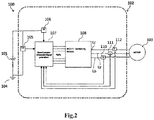
- Fig. 2 illustrates the architecture of the motor control unit (102) of the electric machine (100).
- the motor control unit (102) is electrically connecting the power source (101) to the electric motor (103).
- the motor control unit (102) comprises a plurality of first sensors (105,106) adapted to sense a DC voltage (Vdc) and a DC current (I dc ).
- the plurality of first sensors (105,106) are DC voltage sensor (105) connected across the power source (101) to sense the voltage of the power source (101) and the DC current sensor (106) is connected to the positive terminal of the power source (101) to sense the current received from the power source (101) to the electric motor (103).
- the plurality of first sensors (105,106) is connected to a microcontroller (107).
- the plurality of first sensors (105,106) can be either halls based isolated sensors or shunt based sensors.
- the microcontroller (107) is capable of generating a high frequency wave of sinusoidal currents.
- the microcontroller (107) is connected to a MOSFET switching unit (108) and the MOSFET switching unit (108) is controlled by the sinusoidal current generated by the microcontroller (107) to enable a bridge operation (or the MOSFET switching).
- phase lines (Lr, Ly, Lb) of the electric motor (103) After the bridge operation of the MOSFET switching unit (108).
- Each of the phase lines (Lr, Ly, Lb) connecting the different phases of the electric motor (103) is provided with plurality of second sensors (110,111,112).
- the plurality of the second sensors (110,111,112) are adapted to sense the high frequency wave of sinusoidal currents (Ir, Iy, Ib) in the each of the phase lines (Lr, Ly, Lb).
- the sinusoidal current of high frequency is kept in close proximity to the rated frequency of the electric machine to get a high frequency sinusoidal current.
- the plurality of the second sensors (110,111,112) can be hall based isolated sensors or shunt based sensors
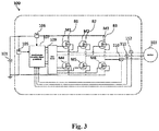
- Fig. 3 illustrates the circuit level diagram of the present subject matter.
- the three-phase excitation winding is disposed in the stator (not shown) of the electric motor (103).
- the sinusoidal current is provided to the electric motor (103) after the bridge operation of the MOSFET switching unit (108) and plurality of the second sensors (110,111,112) for each phase winding of the electric motor (103) sense the phase current (Ir, Iy, Ib) and sent it to the microcontroller (107) to determine root mean square (rms) value of the phase currents (Ir, Iy, Ib).
- phase windings are connected in a star pattern through one or more MOSFET switches (M1, M2, M3, M4, M5, M6) in the MOSFET switching unit (108).
- MOSFET switching unit (108) is also called six pulse half bridge circuit or B6 bridge circuit functioning as a commutation device.
- a first bridge (B1) of the MOSFET switching unit (108) comprises M1 and M4 MOSFETS.
- the central node of the first bridge (B1) connects to a red phase (R) of the electric motor (103).
- a second bridge (B2) of the MOSFET switching unit (108) comprises M2 and M5 MOSFETS and the central node of the second bridge (B2) connects to a yellow phase (Y) of the electric motor (103).
- a third bridge (B3) of the MOSFET switching unit (108) comprises M3 and M6 MOSFETS and the central node of the third bridge (B3) connects to a blue phase (B) of the electric motor (103).
- a gate driver (109) is provided which connects the MOSFET switches (M1, M2, M3, M4, M5, M6) in the MOSFET switching unit (108) to the microcontroller (107).
- the microcontroller (107) enables the gate driver (109) to actuate the switching of the MOSFET switches (M1, M2, M3, M4, M5, M6) by controlling one or more gate terminals of the MOSFET switches (M1, M2, M3, M4, M5, M6).
- phase current 'Ir' flows through the red phase (R) of the electric motor (103), phase current 'Iy' flow through the yellow phase (Y) of the electric motor (103) and the phase current 'Ib' flows through the blue phase (B) of the electric motor (103).
- the microcontroller (107) is adapted to calculate the root means square current (Irms) of the phase current (Ir, Iy, Ib) in the plurality of phase lines (Lr, Ly, Lb).
- Irms root means square current
- the resistance in the phase winding can be determined and based on the value of each phase winding resistance corresponding temperature can be determined based on the temperature co-efficient of the winding material as per following equations of physics.
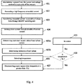
- Fig. 4 illustrates the flow diagram of the method of controlling the electric machine (100).
- a power is determined from the direct voltage (Vdc) and direct current (Idc) detected by the plurality of first sensors (105,106).
- the direct voltage (Vdc) is detected across the power source (101) and the direct current (Idc) is received by the microcontroller (107) from the power source (101).
- the microcontroller (107) generates a high frequency sinusoidal current.
- the sinusoidal current is transferred to said one or more phase lines (Lr, Ly, Lb) of the electric motor (103) after the bridge operation of the MOSFET switching unit (108).
- step 404 the plurality of the second sensors (110, 111, 112) sense the phase currents (Ir, Iy, Ib) in each phase line (Lr, Ly, Lb) of the electric motor (103).
- the microcontroller (107) determines root mean square values of each phase current, in step 405a,and based on the root mean square current (Irms) of each phase and the direct power (P)determined based on the direct voltage (Vdc) and direct current (Idc) as stated in step 401, corresponding resistance of each phase lines (Lr, Ly, Lb) is determined through calculated direct power (P) and root mean square current (Irms) values in step 405b.
- the microcontroller (107) determines the temperature of the electric machine based on the resistance of the phase lines (Lr, Ly, Lb). The temperature increases with the increase in the resistance as the temperature is directly proportional to the resistance and also the temperature coefficient of resistance ( ⁇ ) is positive for a copper material used in the winding of the electric motor (103) which makes the temperature increase with the increase in resistance of the winding as mentioned in the above equation.
- the microcontroller (107) detects a current temperature of the phase lines of the electric motor (103) and in step 408, the microcontroller (107) compares the detected current temperature of the electric motor (103) with a predetermined temperature (To).
- step 407 if the temperature of the electric motor (103) is found to be greater than the predetermined temperature (To) then the power supply from the power source (101) to the electric motor (103) is disconnected till the time the temperature of the electric motor (103) falls below the predetermined temperature (To).No action is taken in step 209, when the temperature of the electric motor (103) is less than the predetermined temperature (To).
Landscapes
- Engineering & Computer Science (AREA)
- Power Engineering (AREA)
- Control Of Ac Motors In General (AREA)
Abstract
Description
- The present subject matter generally relates to an electric machine. The present subject matter specifically but not exclusively relates to control the operation of the electric machine of a vehicle.
- Electric motor is an essential power source in an electric vehicle or hybrid vehicle. The performance of the motor affects the overall performance of the electric vehicle. An electric motor comprises of a rotor and a stator. The stator includes windings, permanent magnets or metal sheets called laminators. The stator in the electric motor provides a rotary magnetic field to drive the rotary armature.
- The electric motor performance directly affects the overall performance of a vehicle or any machine running on electric motor. The electric motor windings heat up when operated under extreme load thereby reducing the efficiency of the vehicle. As such, the propulsion system requires cooling systems, not only for the electric motor but also for the battery banks in order to ensure efficient operation and maximizing the electric components and vehicle lifetime.
- The detailed description is described with reference to the accompanying figures. The same numbers are used throughout the drawings to reference like features and components.
-
Fig. 1 illustrates a block diagram of the present subject matter depicting an electric machine. -
Fig. 2 illustrates the architecture of the motor control unit of the electric machine. -
Fig.3 illustrates the circuit level diagram of the electric motor. -
Fig.4 illustrates the flow diagram of the method of controlling the electric machine - It is always necessary that the temperature of the motor does not increase beyond a certain threshold which may affect the drivability of the vehicle. Various means have been used for this purpose such as thermistors or other temperature detectors placed on the motor windings to respond directly to the temperature, or current responsive devices for tripping the motor circuit breaker in response to excessive current which would produce overheating if allowed to continue.
- There are resistance measuring devices such as multimeter type instrument which is able to measure the resistance up to 100 Ohms and hence the multimeter type instrument can be optimum for small size machine which may has the phase winding resistance in the range of 10 to 100 Ohm. Larger machines with lower winding resistance use four terminal bridge like Kevin bridge for achieving the accuracy. But Kevin bridge has problems related to high requirement of current for obtaining better sensivity, requirement of manual balancing and also the galvanometer to detect balance condition.
- Another known method to measure temperature of the motor winding is by introducing a small direct current component into the motor current which can be done by connecting an asymmetrical resistance device in the motor circuit. The resistance of the motor winding can be determined from measuring the direct current component and the corresponding voltage. But these methods have their own short coming like limit in the range of measuring the resistance along with low precision due to the resistance measurement circuit which compresses the scale at a higher values of the resistance, error prone methods like balancing issues.But the common issue in all the above mentioned methods is the requirement of an additional component to measure the resistance which leads to increase in the cost and also at the same time making the overall system bulky. Also, introducing a new component leads to dependency on the introduced component which reduces the reliability of the motor.
- The electric motor uses inbuilt sensor for performing vital function such as detection of phase current and phase voltage and some sensor provided in the electric motor used for measuring the power drawn from the battery to run the electric motor. In order to overcome the above mentioned disadvantages the present subject matter enables the sensors, provided in the electric motor, to measure the resistance in each of the winding by a controller and thereby controlling the operation of the electric motor by generating a high frequency sinusoidal signal and detecting the resistance of each winding. Depending on the resistance, a temperature of the winding is measured and the operation of the electric motor is controlled based on the temperature. The present subject matter, hence, provides an advantage of overcoming the problems mentioned in the prior art like using an extra element, packaging constraint etc.
- Further cooling the electric motor in a saddle type two wheeled vehicle which is typically compact in layout, an additional challenge persists which is related to space and packaging constraint. Additionally, the means to provide cooling mechanism adds to the challenge of limited space. Therefore, there exists a challenge of designing a compact, low cost, high reliability electric machine which can safely operate at rated as well as over-rated loads without going into adverse thermal run-away or catastrophic failure.
- Hence, in order to overcome the above mentioned challenges the present subject matter provides an electric machine which can detect the temperature of the winding by eliminating the requirement of any additional components such as thermistors to determine the temperature and controlling the starting operation of the electric machine based on the detected temperature and thereby reducing additional cost by eliminating the need of an additional component e.g. a sensor to measure temperature and also providing a compact packaging. Also, if an additional sensor fails the system becomes highly vulnerable and may lead to catastrophic failure like fire, thermal runaway or the rider may get stranded in the middle of a road. Thus, the reliability requirement of the sensor is very high leading to high cost of sensor. Without using an additional component, the reliability of the electric machine operation increases as the electric machine is not dependent on any additional component. Further, the present subject matter enables the driver of the vehicle to know when the electric machine needs repair since over due course of time the resistance of the windings increases and the same would be indicated to the user by the diagnostic system in the controller of the electric machine.
- Another aspect of the present subject matter provides a motor control unit to control a power supply to an electric motor. The motor control unit comprises a microcontroller that generates a high frequency sinusoidal current and transfers the high frequency sinusoidal current to one or more phase lines of the electric motor. The sinusoidal current of high frequency is adjusted in close proximity to a rated frequency of the electric machine to get a suitable sinusoidal current.
- Still another aspect of the present subject matter provides a microcontroller which enables a plurality of first sensors provided in the electric machine to detect a direct voltage and direct current from a power source supplied to the electric motor. The microcontroller determines a direct current power from the detected values of the direct voltage and the direct current.
- Yet another aspect of the subject matter is to provide a microcontroller which enables a plurality of second sensors provided in one or more phase lines of the electric machine to detect one or more phase currents.
- Another aspect of the present subject matter is to provide a commutation device such as a MOSFET switching unit also called six pulse half bridge circuit or B6 bridge circuit functioning as a commutation device. The MOSFET switching unit receives the sinusoidal current from the microcontroller and performs the bridge operation. The MOSFET switching unit comprises of one or more bridges connected to said one or more phase lines of the electric motor. Each bridge of the MOSFET switching unit comprises two MOSFET switches to perform switching operation.
- Another aspect of the present subject matter is to determine a resistance for said one or more phase lines of the electric motor by processing a root mean square value of one or more phase current of said one or more phase lines and the direct current power from the power source.
- Still another aspect of the present subject matter is to determine a current temperature from said resistance and comparing said current temperature with a predetermined temperature (temperature value set by the manufacturer) and controlling the actuation- of the electric motor based on the current temperature of the phase lines.
- The above aspects and the associated advantages of the present subject matter will be better understood through following description, appended claims and accompanying drawings.
-
Fig. 1 illustrates a block diagram of the present subject matter depicting an electric machine (100) comprising a power source (101) such as a battery to drive an electric motor (103). A motor control unit (102) controls the power supply to the electric motor (103). -
Fig. 2 illustrates the architecture of the motor control unit (102) of the electric machine (100). The motor control unit (102) is electrically connecting the power source (101) to the electric motor (103). The motor control unit (102) comprises a plurality of first sensors (105,106) adapted to sense a DC voltage (Vdc) and a DC current (Idc). The plurality of first sensors (105,106) are DC voltage sensor (105) connected across the power source (101) to sense the voltage of the power source (101) and the DC current sensor (106) is connected to the positive terminal of the power source (101) to sense the current received from the power source (101) to the electric motor (103). - The plurality of first sensors (105,106) is connected to a microcontroller (107). The microcontroller (107) is adapted to receive input from said plurality of first sensors (105,106) and determines a direct power (P) received from the power source (101) [P=VdcIdc]. The plurality of first sensors (105,106) can be either halls based isolated sensors or shunt based sensors.
- The microcontroller (107) is capable of generating a high frequency wave of sinusoidal currents. The microcontroller (107) is connected to a MOSFET switching unit (108) and the MOSFET switching unit (108) is controlled by the sinusoidal current generated by the microcontroller (107) to enable a bridge operation (or the MOSFET switching).
- By generating and supplying a high frequency of the sinusoidal current, a torque is generated which provides a small movement in the electric motor. The high frequency sinusoidal current generated by the microcontroller (107) which is then supplied to one or more phase lines (Lr, Ly, Lb) of the electric motor (103) after the bridge operation of the MOSFET switching unit (108). Each of the phase lines (Lr, Ly, Lb) connecting the different phases of the electric motor (103) is provided with plurality of second sensors (110,111,112). The plurality of the second sensors (110,111,112) are adapted to sense the high frequency wave of sinusoidal currents (Ir, Iy, Ib) in the each of the phase lines (Lr, Ly, Lb). The sinusoidal current of high frequency is kept in close proximity to the rated frequency of the electric machine to get a high frequency sinusoidal current. The plurality of the second sensors (110,111,112) can be hall based isolated sensors or shunt based sensors
-
Fig. 3 illustrates the circuit level diagram of the present subject matter. The three-phase excitation winding is disposed in the stator (not shown) of the electric motor (103). The sinusoidal current is provided to the electric motor (103) after the bridge operation of the MOSFET switching unit (108) and plurality of the second sensors (110,111,112) for each phase winding of the electric motor (103) sense the phase current (Ir, Iy, Ib) and sent it to the microcontroller (107) to determine root mean square (rms) value of the phase currents (Ir, Iy, Ib). - The phase windings are connected in a star pattern through one or more MOSFET switches (M1, M2, M3, M4, M5, M6) in the MOSFET switching unit (108). The MOSFET switching unit (108) is also called six pulse half bridge circuit or B6 bridge circuit functioning as a commutation device.
- A first bridge (B1) of the MOSFET switching unit (108) comprises M1 and M4 MOSFETS. The central node of the first bridge (B1) connects to a red phase (R) of the electric motor (103). Similarly, a second bridge (B2) of the MOSFET switching unit (108) comprises M2 and M5 MOSFETS and the central node of the second bridge (B2) connects to a yellow phase (Y) of the electric motor (103). A third bridge (B3) of the MOSFET switching unit (108) comprises M3 and M6 MOSFETS and the central node of the third bridge (B3) connects to a blue phase (B) of the electric motor (103).
- A gate driver (109) is provided which connects the MOSFET switches (M1, M2, M3, M4, M5, M6) in the MOSFET switching unit (108) to the microcontroller (107). The microcontroller (107) enables the gate driver (109) to actuate the switching of the MOSFET switches (M1, M2, M3, M4, M5, M6) by controlling one or more gate terminals of the MOSFET switches (M1, M2, M3, M4, M5, M6).
- The phase current 'Ir' flows through the red phase (R) of the electric motor (103), phase current 'Iy' flow through the yellow phase (Y) of the electric motor (103) and the phase current 'Ib' flows through the blue phase (B) of the electric motor (103).
- The microcontroller (107) is adapted to calculate the root means square current (Irms) of the phase current (Ir, Iy, Ib) in the plurality of phase lines (Lr, Ly, Lb). Through root mean square current in each phase, the resistance in the phase winding can be determined and based on the value of each phase winding resistance corresponding temperature can be determined based on the temperature co-efficient of the winding material as per following equations of physics.


- Where 'α' is temperature coefficient of the phase line of the electric motor.
- Ir = Current in red phase of the winding
- Iy=Current in yellow phase of the winding
- Ib= Current in yellow phase of the winding
- iα = α phase current in two phase stationary reference frame system
- iβ = β phase current in two phase stationary reference frame system
- im= Root Mean Square value of the motor current (Irms)
- Tref = Temperature at which reference motor resistance is measured
- Rref = Measured value of motor resistance at temperature Tref
- P = power dissipated in the motor
-
Fig. 4 illustrates the flow diagram of the method of controlling the electric machine (100). Instep 401, a power is determined from the direct voltage (Vdc) and direct current (Idc) detected by the plurality of first sensors (105,106). The direct voltage (Vdc) is detected across the power source (101) and the direct current (Idc) is received by the microcontroller (107) from the power source (101). Instep 402, the microcontroller (107) generates a high frequency sinusoidal current. Instep 403, the sinusoidal current is transferred to said one or more phase lines (Lr, Ly, Lb) of the electric motor (103) after the bridge operation of the MOSFET switching unit (108). - In
step 404, the plurality of the second sensors (110, 111, 112) sense the phase currents (Ir, Iy, Ib) in each phase line (Lr, Ly, Lb) of the electric motor (103). After sensing the phase current (Ir, Iy, Ib), instep 404, the microcontroller (107) determines root mean square values of each phase current, instep 405a,and based on the root mean square current (Irms) of each phase and the direct power (P)determined based on the direct voltage (Vdc) and direct current (Idc) as stated instep 401, corresponding resistance of each phase lines (Lr, Ly, Lb) is determined through calculated direct power (P) and root mean square current (Irms) values instep 405b. - The microcontroller (107) determines the temperature of the electric machine based on the resistance of the phase lines (Lr, Ly, Lb). The temperature increases with the increase in the resistance as the temperature is directly proportional to the resistance and also the temperature coefficient of resistance (α) is positive for a copper material used in the winding of the electric motor (103) which makes the temperature increase with the increase in resistance of the winding as mentioned in the above equation. In
step 406, the microcontroller (107) detects a current temperature of the phase lines of the electric motor (103) and instep 408, the microcontroller (107) compares the detected current temperature of the electric motor (103) with a predetermined temperature (To). Then instep 407, if the temperature of the electric motor (103) is found to be greater than the predetermined temperature (To) then the power supply from the power source (101) to the electric motor (103) is disconnected till the time the temperature of the electric motor (103) falls below the predetermined temperature (To).No action is taken in step 209, when the temperature of the electric motor (103) is less than the predetermined temperature (To).
Claims (11)
- An electric machine (100) comprising:an electric motor (103) to receive a power from a power source (101);a motor control unit (102) to control said power from said power source (101) to said electric motor (103);a commutation device to receive a high frequency sinusoidal current from a microcontroller (107);a plurality of first sensors (105,106) adapted to sense a direct current (Idc) from said power source (101) and a direct voltage (Vdc) across said power source (106);said microcontroller (107) to generate a sinusoidal current to enable excitation of said commutation device; anda plurality of second sensors (110,111,112) connected to one or more phase lines (Lr, Ly, Lb) of said electric motor (103) adapted to sense one or more phase currents (Ir, Iy, Ib).
- The electric machine as claimed in claim 1, wherein said commutation device is a MOSFET switching unit (108) to enable a bridge operation.
- The electric machine as claimed in claim 1, wherein said microcontroller (107) actuates said electric motor (103) by comparing a current temperature of said one or more phase lines (Lr, Ly, Lb) with a predetermined temperature (To).
- The electric machine as claimed in claim 1, wherein a frequency of said sinusoidal current is in proximity to the frequency rating of said electric motor (103).
- The electric machine as claimed in claim 1, wherein said microcontroller (107) determines a direct current power (P) from input received from said plurality of first sensors (105,106).
- The electric machine as claimed in claim 1, wherein said microcontroller (107) determines a root mean square current (Irms) for said one or more phase lines (Lr, Ly, Lb) after input received from plurality of second sensors (110,111,112).
- The electric machine as claimed in claim 1, wherein said current temperature is determined with said direct current power (P) and said root mean square current (Irms).
- The electric machine as claimed in claim 1, wherein said MOSFET switching unit (108) comprising plurality of MOSFET switches (M1, M2, M3, M4, M5, M6) forming a six pulse half bridge circuit.
- A method of controlling an electric machine (100) comprising the steps of:determining a direct current power (P) from a direct current (Idc) and direct voltage (Vdc) detected by a plurality of first sensors (105,106);generating a high frequency sinusoidal current;transferring said sinusoidal current to plurality of phase lines(Lr, Ly, Lb) through a MOSFET switching unit (108);sensing one or more phase currents (Ir,Iy,Ib) through plurality of second sensors (110,111,112);determining a root mean square value of said one or more phase currents (Ir,Iy,Ib);detecting a current temperature;comparing said current temperature with a predetermined temperature (To); anddisconnecting power supply to a electric motor (103) when said current temperature is greater than (To).
- The method of controlling an electric machine (100) as claimed in claim 9, wherein said determining a current temperature comprises the steps of:processing said root means square value of said one or more phase currents (Ir,Iy,Ib) and said direct current power (P);determining a resistance of said plurality of phase lines (Lr, Ly, Lb); anddetermining said current temperature from said resistance.
- An electric machine (100) for a vehicle comprising:an electric motor (103) to receive a power from one or more power source (101);amotor control unit (102) to control said power from said one or more power source (101) to said electric motor (103);a plurality of first sensors (105,106) adapted to sense a direct current (Idc) from said power source (101) and a direct voltage (Vdc) across said power source (106);said motor control unit (102) comprising a microcontroller (107) to generate a sinusoidal current to enable excitation of a commutation device; a plurality of second sensors (110,111,112) connected to one or more phase lines (Lr, Ly, Lb) of said electric motor (103) adapted to sense one or more phase currents (Ir, Iy, Ib); andsaid microcontroller (107) actuates said electric motor (103) by comparing a current temperature of said one or more phase lines (Lr, Ly, Lb) with a predetermined temperature (To).
Applications Claiming Priority (1)
| Application Number | Priority Date | Filing Date | Title |
|---|---|---|---|
| IN202041022481 | 2020-05-28 |
Publications (2)
| Publication Number | Publication Date |
|---|---|
| EP3917001A1 true EP3917001A1 (en) | 2021-12-01 |
| EP3917001B1 EP3917001B1 (en) | 2025-07-02 |
Family
ID=76180900
Family Applications (1)
| Application Number | Title | Priority Date | Filing Date |
|---|---|---|---|
| EP21176436.0A Active EP3917001B1 (en) | 2020-05-28 | 2021-05-28 | An electric machine und method for controlling an electric machine |
Country Status (3)
| Country | Link |
|---|---|
| EP (1) | EP3917001B1 (en) |
| CN (1) | CN113746403A (en) |
| ES (1) | ES3039930T3 (en) |
Citations (4)
| Publication number | Priority date | Publication date | Assignee | Title |
|---|---|---|---|---|
| JP2007074796A (en) * | 2005-09-06 | 2007-03-22 | Matsushita Electric Ind Co Ltd | Inverter device |
| JP2013021857A (en) * | 2011-07-13 | 2013-01-31 | Toyota Motor Corp | Motor drive control system |
| US20180062553A1 (en) * | 2016-08-31 | 2018-03-01 | Intel Corporation | Monitoring health of electrical equipment |
| CN105490606B (en) * | 2015-12-25 | 2018-08-03 | 杭州乾景科技有限公司 | Guard method for the anti-demagnetization of latent oil AC permanent magnet synchronous motor |
Family Cites Families (7)
| Publication number | Priority date | Publication date | Assignee | Title |
|---|---|---|---|---|
| KR200302114Y1 (en) * | 1998-07-20 | 2003-04-16 | 주식회사 만도 | Protection device of brushless motor controller |
| DE10002242A1 (en) * | 2000-01-20 | 2001-08-02 | Daimler Chrysler Ag | Process for protecting an electric motor against thermal overload |
| JP6298835B2 (en) * | 2014-02-10 | 2018-03-20 | 株式会社日立産機システム | Motor power converter |
| US9331626B2 (en) * | 2014-02-10 | 2016-05-03 | The Chamberlain Group, Inc. | Generating heat in a movable barrier operator |
| DE102016106431A1 (en) * | 2016-04-08 | 2017-10-12 | Ebm-Papst Mulfingen Gmbh & Co. Kg | temperature monitoring |
| WO2018185667A1 (en) * | 2017-04-05 | 2018-10-11 | Tvs Motor Company Limited | Electric machine for a vehicle |
| CN109861625A (en) * | 2019-02-18 | 2019-06-07 | 成都运达科技股份有限公司 | The Temperature Identification and overtemperature prote method of medium-and low-speed maglev train linear motor |
-
2021
- 2021-05-06 CN CN202110490879.2A patent/CN113746403A/en active Pending
- 2021-05-28 ES ES21176436T patent/ES3039930T3/en active Active
- 2021-05-28 EP EP21176436.0A patent/EP3917001B1/en active Active
Patent Citations (4)
| Publication number | Priority date | Publication date | Assignee | Title |
|---|---|---|---|---|
| JP2007074796A (en) * | 2005-09-06 | 2007-03-22 | Matsushita Electric Ind Co Ltd | Inverter device |
| JP2013021857A (en) * | 2011-07-13 | 2013-01-31 | Toyota Motor Corp | Motor drive control system |
| CN105490606B (en) * | 2015-12-25 | 2018-08-03 | 杭州乾景科技有限公司 | Guard method for the anti-demagnetization of latent oil AC permanent magnet synchronous motor |
| US20180062553A1 (en) * | 2016-08-31 | 2018-03-01 | Intel Corporation | Monitoring health of electrical equipment |
Also Published As
| Publication number | Publication date |
|---|---|
| ES3039930T3 (en) | 2025-10-27 |
| EP3917001B1 (en) | 2025-07-02 |
| CN113746403A (en) | 2021-12-03 |
Similar Documents
| Publication | Publication Date | Title |
|---|---|---|
| CN102598502B (en) | Method for checking the plausibility of the torque of an electrical machine and machine controller for controlling an electrical machine and for carrying out the method | |
| JP4229520B2 (en) | Motor control method | |
| US10374532B2 (en) | Apparatus, system and method of fault diagnosis for permanent magnet motor | |
| JP3218954B2 (en) | Abnormality detection device for AC motor control circuit | |
| US8164296B2 (en) | Method and apparatus for determining a field current in brushless electrical machines | |
| KR20140075596A (en) | Estimation of Resistance in Electrical Machines | |
| US20160211789A1 (en) | Control of a rotating field machine | |
| US20120187878A1 (en) | Method for detecting deterioration of permanent magnet in electric motor and system for the method | |
| CN101059552B (en) | Method of screening a resistive short-circuit, system, module and recording medium for this method | |
| EP3631952B1 (en) | Electric machine with integrated power electronics | |
| JP3183759B2 (en) | Load measuring device | |
| EP0644648B1 (en) | Control method and apparatus and malefunction detection method and apparatus for AC motor | |
| EP3917001B1 (en) | An electric machine und method for controlling an electric machine | |
| JPH11304870A (en) | Method for confirming polarity of tertiary winding of meter current transformer, and testing method for ground protective relay using the same | |
| CN112970192A (en) | Method for monitoring continuous state of motor | |
| CN114826082B (en) | Method for checking the temperature of an electric machine model determined by means of a temperature model, and motor vehicle | |
| JP3630103B2 (en) | Fault detection device for servo control system | |
| EP4052049B1 (en) | Three phase current measurement | |
| JP3329672B2 (en) | Induction motor constant measuring device | |
| JP2006141108A (en) | Anomaly detection method and apparatus for three-phase winding induction motor | |
| KR20240131143A (en) | Inverter based-driving apparatus of ac motor capable of measuring insulation degradation | |
| CN119959755A (en) | Method for monitoring an electric machine, rectifier device and drive system | |
| JPH06303791A (en) | Method of compensating temperature of secondary resistor of induction motor | |
| CN122029438A (en) | System and method for monitoring insulation resistance of motor stator | |
| JPH0989694A (en) | Induction motor torque detector |
Legal Events
| Date | Code | Title | Description |
|---|---|---|---|
| PUAI | Public reference made under article 153(3) epc to a published international application that has entered the european phase |
Free format text: ORIGINAL CODE: 0009012 |
|
| STAA | Information on the status of an ep patent application or granted ep patent |
Free format text: STATUS: THE APPLICATION HAS BEEN PUBLISHED |
|
| AK | Designated contracting states |
Kind code of ref document: A1 Designated state(s): AL AT BE BG CH CY CZ DE DK EE ES FI FR GB GR HR HU IE IS IT LI LT LU LV MC MK MT NL NO PL PT RO RS SE SI SK SM TR |
|
| B565 | Issuance of search results under rule 164(2) epc |
Effective date: 20211027 |
|
| STAA | Information on the status of an ep patent application or granted ep patent |
Free format text: STATUS: REQUEST FOR EXAMINATION WAS MADE |
|
| 17P | Request for examination filed |
Effective date: 20220517 |
|
| RBV | Designated contracting states (corrected) |
Designated state(s): AL AT BE BG CH CY CZ DE DK EE ES FI FR GB GR HR HU IE IS IT LI LT LU LV MC MK MT NL NO PL PT RO RS SE SI SK SM TR |
|
| REG | Reference to a national code |
Ref legal event code: R079 Ref country code: DE Ref legal event code: R079 Ref document number: 602021033203 Country of ref document: DE Free format text: PREVIOUS MAIN CLASS: H02P0029024000 Ipc: H02P0029640000 |
|
| GRAP | Despatch of communication of intention to grant a patent |
Free format text: ORIGINAL CODE: EPIDOSNIGR1 |
|
| STAA | Information on the status of an ep patent application or granted ep patent |
Free format text: STATUS: GRANT OF PATENT IS INTENDED |
|
| RIC1 | Information provided on ipc code assigned before grant |
Ipc: H02P 29/024 20160101ALI20241216BHEP Ipc: H02P 29/64 20160101AFI20241216BHEP |
|
| INTG | Intention to grant announced |
Effective date: 20250103 |
|
| GRAS | Grant fee paid |
Free format text: ORIGINAL CODE: EPIDOSNIGR3 |
|
| GRAA | (expected) grant |
Free format text: ORIGINAL CODE: 0009210 |
|
| STAA | Information on the status of an ep patent application or granted ep patent |
Free format text: STATUS: THE PATENT HAS BEEN GRANTED |
|
| AK | Designated contracting states |
Kind code of ref document: B1 Designated state(s): AL AT BE BG CH CY CZ DE DK EE ES FI FR GB GR HR HU IE IS IT LI LT LU LV MC MK MT NL NO PL PT RO RS SE SI SK SM TR |
|
| REG | Reference to a national code |
Ref country code: GB Ref legal event code: FG4D |
|
| REG | Reference to a national code |
Ref country code: CH Ref legal event code: EP |
|
| REG | Reference to a national code |
Ref country code: DE Ref legal event code: R096 Ref document number: 602021033203 Country of ref document: DE |
|
| REG | Reference to a national code |
Ref country code: IE Ref legal event code: FG4D |
|
| REG | Reference to a national code |
Ref country code: ES Ref legal event code: FG2A Ref document number: 3039930 Country of ref document: ES Kind code of ref document: T3 Effective date: 20251027 |
|
| REG | Reference to a national code |
Ref country code: NL Ref legal event code: MP Effective date: 20250702 |
|
| PG25 | Lapsed in a contracting state [announced via postgrant information from national office to epo] |
Ref country code: PT Free format text: LAPSE BECAUSE OF FAILURE TO SUBMIT A TRANSLATION OF THE DESCRIPTION OR TO PAY THE FEE WITHIN THE PRESCRIBED TIME-LIMIT Effective date: 20251103 |
|
| PG25 | Lapsed in a contracting state [announced via postgrant information from national office to epo] |
Ref country code: NL Free format text: LAPSE BECAUSE OF FAILURE TO SUBMIT A TRANSLATION OF THE DESCRIPTION OR TO PAY THE FEE WITHIN THE PRESCRIBED TIME-LIMIT Effective date: 20250702 |
|
| REG | Reference to a national code |
Ref country code: AT Ref legal event code: MK05 Ref document number: 1810437 Country of ref document: AT Kind code of ref document: T Effective date: 20250702 |
|
| PG25 | Lapsed in a contracting state [announced via postgrant information from national office to epo] |
Ref country code: IS Free format text: LAPSE BECAUSE OF FAILURE TO SUBMIT A TRANSLATION OF THE DESCRIPTION OR TO PAY THE FEE WITHIN THE PRESCRIBED TIME-LIMIT Effective date: 20251102 |
|
| PG25 | Lapsed in a contracting state [announced via postgrant information from national office to epo] |
Ref country code: NO Free format text: LAPSE BECAUSE OF FAILURE TO SUBMIT A TRANSLATION OF THE DESCRIPTION OR TO PAY THE FEE WITHIN THE PRESCRIBED TIME-LIMIT Effective date: 20251002 |
|
| REG | Reference to a national code |
Ref country code: LT Ref legal event code: MG9D |
|
| PG25 | Lapsed in a contracting state [announced via postgrant information from national office to epo] |
Ref country code: AT Free format text: LAPSE BECAUSE OF FAILURE TO SUBMIT A TRANSLATION OF THE DESCRIPTION OR TO PAY THE FEE WITHIN THE PRESCRIBED TIME-LIMIT Effective date: 20250702 |
|
| PG25 | Lapsed in a contracting state [announced via postgrant information from national office to epo] |
Ref country code: FI Free format text: LAPSE BECAUSE OF FAILURE TO SUBMIT A TRANSLATION OF THE DESCRIPTION OR TO PAY THE FEE WITHIN THE PRESCRIBED TIME-LIMIT Effective date: 20250702 |
|
| PG25 | Lapsed in a contracting state [announced via postgrant information from national office to epo] |
Ref country code: HR Free format text: LAPSE BECAUSE OF FAILURE TO SUBMIT A TRANSLATION OF THE DESCRIPTION OR TO PAY THE FEE WITHIN THE PRESCRIBED TIME-LIMIT Effective date: 20250702 |
|
| PG25 | Lapsed in a contracting state [announced via postgrant information from national office to epo] |
Ref country code: GR Free format text: LAPSE BECAUSE OF FAILURE TO SUBMIT A TRANSLATION OF THE DESCRIPTION OR TO PAY THE FEE WITHIN THE PRESCRIBED TIME-LIMIT Effective date: 20251003 |
|
| PG25 | Lapsed in a contracting state [announced via postgrant information from national office to epo] |
Ref country code: SE Free format text: LAPSE BECAUSE OF FAILURE TO SUBMIT A TRANSLATION OF THE DESCRIPTION OR TO PAY THE FEE WITHIN THE PRESCRIBED TIME-LIMIT Effective date: 20250702 Ref country code: CZ Free format text: LAPSE BECAUSE OF FAILURE TO SUBMIT A TRANSLATION OF THE DESCRIPTION OR TO PAY THE FEE WITHIN THE PRESCRIBED TIME-LIMIT Effective date: 20250702 |
|
| PG25 | Lapsed in a contracting state [announced via postgrant information from national office to epo] |
Ref country code: LV Free format text: LAPSE BECAUSE OF FAILURE TO SUBMIT A TRANSLATION OF THE DESCRIPTION OR TO PAY THE FEE WITHIN THE PRESCRIBED TIME-LIMIT Effective date: 20250702 |
|
| PG25 | Lapsed in a contracting state [announced via postgrant information from national office to epo] |
Ref country code: PL Free format text: LAPSE BECAUSE OF FAILURE TO SUBMIT A TRANSLATION OF THE DESCRIPTION OR TO PAY THE FEE WITHIN THE PRESCRIBED TIME-LIMIT Effective date: 20250702 Ref country code: BG Free format text: LAPSE BECAUSE OF FAILURE TO SUBMIT A TRANSLATION OF THE DESCRIPTION OR TO PAY THE FEE WITHIN THE PRESCRIBED TIME-LIMIT Effective date: 20250702 |
|
| PG25 | Lapsed in a contracting state [announced via postgrant information from national office to epo] |
Ref country code: RS Free format text: LAPSE BECAUSE OF FAILURE TO SUBMIT A TRANSLATION OF THE DESCRIPTION OR TO PAY THE FEE WITHIN THE PRESCRIBED TIME-LIMIT Effective date: 20251002 |
|
| PG25 | Lapsed in a contracting state [announced via postgrant information from national office to epo] |
Ref country code: SM Free format text: LAPSE BECAUSE OF FAILURE TO SUBMIT A TRANSLATION OF THE DESCRIPTION OR TO PAY THE FEE WITHIN THE PRESCRIBED TIME-LIMIT Effective date: 20250702 |
|
| PG25 | Lapsed in a contracting state [announced via postgrant information from national office to epo] |
Ref country code: DK Free format text: LAPSE BECAUSE OF FAILURE TO SUBMIT A TRANSLATION OF THE DESCRIPTION OR TO PAY THE FEE WITHIN THE PRESCRIBED TIME-LIMIT Effective date: 20250702 |
|
| PG25 | Lapsed in a contracting state [announced via postgrant information from national office to epo] |
Ref country code: SK Free format text: LAPSE BECAUSE OF FAILURE TO SUBMIT A TRANSLATION OF THE DESCRIPTION OR TO PAY THE FEE WITHIN THE PRESCRIBED TIME-LIMIT Effective date: 20250702 Ref country code: EE Free format text: LAPSE BECAUSE OF FAILURE TO SUBMIT A TRANSLATION OF THE DESCRIPTION OR TO PAY THE FEE WITHIN THE PRESCRIBED TIME-LIMIT Effective date: 20250702 |
|
| PLBE | No opposition filed within time limit |
Free format text: ORIGINAL CODE: 0009261 |
|
| STAA | Information on the status of an ep patent application or granted ep patent |
Free format text: STATUS: NO OPPOSITION FILED WITHIN TIME LIMIT |