EP3916958A1 - Systems and methods for providing sensor power - Google Patents
Systems and methods for providing sensor power Download PDFInfo
- Publication number
- EP3916958A1 EP3916958A1 EP21174313.3A EP21174313A EP3916958A1 EP 3916958 A1 EP3916958 A1 EP 3916958A1 EP 21174313 A EP21174313 A EP 21174313A EP 3916958 A1 EP3916958 A1 EP 3916958A1
- Authority
- EP
- European Patent Office
- Prior art keywords
- sensor
- power
- transformer
- cable
- power component
- Prior art date
- Legal status (The legal status is an assumption and is not a legal conclusion. Google has not performed a legal analysis and makes no representation as to the accuracy of the status listed.)
- Pending
Links
Images


Classifications
-
- B—PERFORMING OPERATIONS; TRANSPORTING
- B60—VEHICLES IN GENERAL
- B60R—VEHICLES, VEHICLE FITTINGS, OR VEHICLE PARTS, NOT OTHERWISE PROVIDED FOR
- B60R16/00—Electric or fluid circuits specially adapted for vehicles and not otherwise provided for; Arrangement of elements of electric or fluid circuits specially adapted for vehicles and not otherwise provided for
- B60R16/02—Electric or fluid circuits specially adapted for vehicles and not otherwise provided for; Arrangement of elements of electric or fluid circuits specially adapted for vehicles and not otherwise provided for electric constitutive elements
- B60R16/03—Electric or fluid circuits specially adapted for vehicles and not otherwise provided for; Arrangement of elements of electric or fluid circuits specially adapted for vehicles and not otherwise provided for electric constitutive elements for supply of electrical power to vehicle subsystems or for
-
- H—ELECTRICITY
- H02—GENERATION; CONVERSION OR DISTRIBUTION OF ELECTRIC POWER
- H02J—ELECTRIC POWER NETWORKS; CIRCUIT ARRANGEMENTS OR SYSTEMS FOR SUPPLYING OR DISTRIBUTING ELECTRIC POWER; SYSTEMS FOR STORING ELECTRIC ENERGY
- H02J50/00—Circuit arrangements or systems for wireless supply or distribution of electric power
- H02J50/10—Circuit arrangements or systems for wireless supply or distribution of electric power using inductive coupling
-
- G—PHYSICS
- G01—MEASURING; TESTING
- G01P—MEASURING LINEAR OR ANGULAR SPEED, ACCELERATION, DECELERATION, OR SHOCK; INDICATING PRESENCE, ABSENCE, OR DIRECTION, OF MOVEMENT
- G01P3/00—Measuring linear or angular speed; Measuring differences of linear or angular speeds
- G01P3/42—Devices characterised by the use of electric or magnetic means
- G01P3/44—Devices characterised by the use of electric or magnetic means for measuring angular speed
-
- H—ELECTRICITY
- H02—GENERATION; CONVERSION OR DISTRIBUTION OF ELECTRIC POWER
- H02J—ELECTRIC POWER NETWORKS; CIRCUIT ARRANGEMENTS OR SYSTEMS FOR SUPPLYING OR DISTRIBUTING ELECTRIC POWER; SYSTEMS FOR STORING ELECTRIC ENERGY
- H02J50/00—Circuit arrangements or systems for wireless supply or distribution of electric power
- H02J50/001—Energy harvesting or scavenging
-
- H—ELECTRICITY
- H02—GENERATION; CONVERSION OR DISTRIBUTION OF ELECTRIC POWER
- H02J—ELECTRIC POWER NETWORKS; CIRCUIT ARRANGEMENTS OR SYSTEMS FOR SUPPLYING OR DISTRIBUTING ELECTRIC POWER; SYSTEMS FOR STORING ELECTRIC ENERGY
- H02J50/00—Circuit arrangements or systems for wireless supply or distribution of electric power
- H02J50/005—Mechanical details of housing or structure aiming to accommodate the power transfer means, e.g. mechanical integration of coils, antennas or transducers into emitting or receiving devices
-
- G—PHYSICS
- G08—SIGNALLING
- G08C—TRANSMISSION SYSTEMS FOR MEASURED VALUES, CONTROL OR SIMILAR SIGNALS
- G08C17/00—Arrangements for transmitting signals characterised by the use of a wireless electrical link
- G08C17/02—Arrangements for transmitting signals characterised by the use of a wireless electrical link using a radio link
-
- H—ELECTRICITY
- H02—GENERATION; CONVERSION OR DISTRIBUTION OF ELECTRIC POWER
- H02J—ELECTRIC POWER NETWORKS; CIRCUIT ARRANGEMENTS OR SYSTEMS FOR SUPPLYING OR DISTRIBUTING ELECTRIC POWER; SYSTEMS FOR STORING ELECTRIC ENERGY
- H02J2105/00—Networks for supplying or distributing electric power characterised by their spatial reach or by the load
- H02J2105/30—Networks for supplying or distributing electric power characterised by their spatial reach or by the load the load networks being external to vehicles, i.e. exchanging power with vehicles
- H02J2105/33—Networks for supplying or distributing electric power characterised by their spatial reach or by the load the load networks being external to vehicles, i.e. exchanging power with vehicles exchanging power with road vehicles
- H02J2105/37—Networks for supplying or distributing electric power characterised by their spatial reach or by the load the load networks being external to vehicles, i.e. exchanging power with vehicles exchanging power with road vehicles exchanging power with electric vehicles [EV] or with hybrid electric vehicles [HEV]
Definitions
- the subject matter described relates to systems and methods for use in providing power to sensors, for example sensors of a vehicle.
- Alternating current (AC) power components may be used in a variety of applications.
- AC traction motors may be used in connection with vehicle propulsion.
- Such components may have a number of sensors associated with them.
- Providing power to sensors in such applications may encounter a number of challenges. For example, if power is provided to individual sensors via cables from a remote source, the associated cables may be expensive, and difficult to route. Such cables may result in increased complexity and expense of assembling and maintaining systems (e.g., vehicles).
- batteries the batteries may provide undesirable additional weight. For example, in vehicle applications, the extra weight of batteries may result in additional wear on related components.
- information from sensors may be provided intermittently, resulting in periods of time where sensor information is not known. These batteries also need periodic replacement and have performance impact based on ambient conditions. It may be desirable to have systems and methods that differ from those that are currently available.
- a system may include an alternating current (AC) power component, a cable, a sensor transformer, and a sensor.
- the cable is coupled to the AC power component and can conduct current to the AC power component.
- the sensor transformer may include a coil disposed proximate to the cable. The coil generates an induced voltage responsive to conduction of the current through the cable.
- the sensor is coupled to the sensor transformer and receives sensor power from the sensor transformer. The sensor obtains information corresponding to operation of the AC power component.
- a method may include conducting current to an alternating current (AC) power component via a cable.
- the method may include generating a sensor power signal with a sensor transformer responsive to the current conducted to the AC power component via the cable. Further, the method may include transmitting the sensor power signal to a sensor. The method may include obtaining information corresponding to operation of the AC power component with the sensor.
- AC alternating current
- a system may include a drive assembly, a cable, a sensor transformer, and a sensor.
- the drive assembly may include a traction motor.
- the cable is coupled to the traction motor and can conduct current to the traction motor.
- the sensor transformer may include a coil disposed proximate to the cable. The coil generates an induced voltage responsive to conduction of the current through the cable.
- the sensor transformer is mounted to the drive assembly proximate the cable.
- the sensor is coupled to the sensor transformer and receives power from the sensor transformer.
- the sensor is mounted to the drive assembly and can obtain information corresponding to operation of the drive assembly.
- Embodiments of the subject matter described herein relate to systems and methods for providing power to sensors.
- various embodiments relate to the use of a sensor transformer located proximate to a corresponding sensor and providing power to the sensor.
- the sensor transformer in various embodiments is disposed proximate a cable of an AC power component, and generates an induced voltage responsive to power running through the cable.
- the power for a sensor may be generated relatively close to the sensor, without the need for lengthy, costly, and complex wiring runs and/or may reduce or eliminate undesirable weight and/or longevity issues associated with solar panels, batteries, or other energy storage devices.
- Suitable vehicles may include automobiles, trucks, buses, mining vehicles, marine vessels, aircraft, agricultural vehicles, and the like. And, while embodiments of the invention may be applied to stationary applications, most stationary applications do not have the same constraints and challenges associated with vehicles such that the heavy battery systems, and grid connectivity may be more appropriate.
- FIG. 1 illustrates a schematic diagram of a system 100.
- the depicted system 100 may include an alternating current (AC) power component 110, a cable 120, a sensor transformer 130, and a sensor 140.
- the cable is coupled to the AC power component, and provides current to the AC power component.
- the sensor transformer may generate a voltage responsive to current moving through the cable, and thereby may provide power to the sensor.
- the sensor transformer may include a coil 132. While the coil is represented as a single block in Figure 1 , multiple coils may be used in various embodiments.
- the coil may be disposed proximate the cable and may generate an induced voltage responsive to conduction of current through the cable. With regard to distances between the cable and the sensor transformer, the sensor transformer in various embodiments may be located within a few centimeters or less of the cable.
- the sensor transformer in various embodiments may be mounted on or near the AC power component (or an assembly including the AC power component) and relatively close to the sensor.
- a suitable sensor transformer may be a device used to acquire, generate, or receive sensor power to be transferred to the sensor, and may be selected based at least in part on application specific criteria.
- the senor may be coupled to the sensor transformer (e.g., via a wire or cable) and may receive sensor power from the sensor transformer.
- the sensor may be mounted relatively near the sensor transformer.
- the sensor may be within 10-20 feet of the sensor transformer in various embodiments.
- the sensor can obtain information corresponding to operation of the AC power component. With the proper sensor selection, the sensor may detect one or more of temperature, fluid level, vibration, or frequency content of a signal, among others. This may be done while providing sensor power to the sensor.
- Information corresponding to operation of the AC power component may include information regarding related components.
- the AC power component is a traction motor
- information corresponding to operation of the traction motor may include information regarding associated axles, gears, bearings, and the like.
- information corresponding to operation of a traction motor may include gear case oil level, information regarding operation of motor bearings, etc.
- each sensor may have a dedicated sensor transformer, or one sensor transformer may provide sensor power to multiple sensors, depending on conditions of a particular application, for example amounts of sensor power required, locations available for sensor transformers, and distance and routing options between transformers and sensors.
- the AC power component may be disposed on a vehicle.
- Figure 2 provides a schematic view of an example system in which an AC power component may be disposed on a vehicle 205.
- the vehicle in the illustrated embodiment is a rail vehicle (e.g., locomotive).
- the AC power component is a traction motor 210.
- the depicted traction motor is part of a drive assembly 220.
- the sensor transformer and the sensor are both mounted to the drive assembly.
- the drive assembly may include multiple traction motors 210.
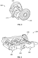
- Figure 3 provides a perspective view of a motor assembly 300 that may include the traction motor and wheels 310.
- Figure 4 provides a perspective view of a drive assembly that may include a truck 230 and three motor assemblies.
- a sensor transformer mounted to one motor assembly may provide sensor power to plural sensors on one or more other motor assemblies of the truck.
- Sensors may be placed at or near various locations of the drive assembly to detect various properties (e.g., temperature, fluid level, vibration) associated with one or more components or aspects of the drive assembly.
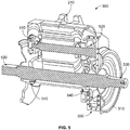
- Figure 5 provides a sectional view of the motor assembly.
- the motor assembly may include various bearings - a motor non-pinion end rolling element bearing 510, a motor pinion end rolling element bearing 520, axle rolling element bearing locations 530, and U tube rolling element bearings 540.
- the motor assembly may include a gear case 550 and associated gears. Sensors may be disposed proximate to corresponding bearing locations, gears, and/or the gear case to detect one or more properties or conditions associated with the bearings, gears, and/or the gear case.
- the sensor transformer is located proximate to the cable (e.g., close enough to the cable to generate a sufficient amount of sensor power for the sensor).
- the amount of sensor power required for sensor operation may be very small relative to the higher current and power utilized by the AC power component, so that the providing of sensor power to the sensor via the sensor transformer does not have a meaningful effect on operation of the AC power component.
- traction motors can have power ratings of more than 100 kiloWatts whereas sensor requirements may be several milliwatts.
- the sensor transformer may be mounted to a component or device that secures and/or routes the cable.
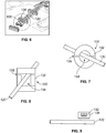
- Figure 6 provides a perspective view of an example cable that passes through a cleat 600.
- the cleat may be mounted to a drive assembly (e.g., drive assembly).
- the sensor transformer is mounted to the cleat.
- the sensor transformer may form the cable cleat.
- a three cable system is shown in Figure 6 , but, in other embodiments a single cable (or any other number of cable) system may be employed.
- the sensor transformer defines an opening 134 through which the cable passes.
- Figure 7 provides a perspective view of an example coil that has an opening through which the cable passes.
- Figure 8 provides a perspective view of another example coil that has an opening through which the cable passes.
- the example coils of Figures 7 and 8 are both examples of split-core transformers having gaps 135 between core portions.
- a solid core transformer having an opening may be employed.
- the cable may not pass through the coil.
- Figure 9 illustrates an example coil that is disposed near a cable, but the cable does not pass through the coil.
- Figure 10 provides an electrical schematic view of aspects of an example system showing connections between the sensor transformer, sensor, and various components.
- the system may include a band pass filter 1010 that is interposed between the sensor transformer and the sensor. Current from the sensor transformer to the sensor is first filtered by the band pass filter, so that only current at selected frequencies is provided to the sensor.
- the system may include a load element 1020.
- the load element 1020 may be coupled to the sensor transformer (e.g., via switch 1021), and can dissipate excess current or voltage (e.g., current in excess of a rating of the sensor, or current when an energy storage device selectively coupled to the sensor is full or above a threshold value).
- excess current or voltage e.g., current in excess of a rating of the sensor, or current when an energy storage device selectively coupled to the sensor is full or above a threshold value.
- the switch may be closed to allow current to flow from the sensor transformer to the load element.
- the switch may be opened to prevent current from being directed to the load element.
- the depicted example system of Figure 10 may include a storage element 1030.
- the storage element in various embodiments may be a capacitor, or, as another example, a battery.
- the storage element may be coupled to the sensor. When current from the sensor transformer is available, the storage element may be charged, and when current from the sensor transformer is not available, the storage element may be used to provide sensor power to the sensor. For example, in a first state of operation of the AC power component when sensor power from the sensor coil is readily available, the storage element may be charged, with the stored energy later used for the sensor at a time when sensor power is not being derived from the AC power component and therefore is not as readily available.
- the storage element may store sufficient energy for a relatively short amount of time (e.g., 8 hours), allowing for a relatively small and lightweight capacitor (e.g., relative to larger, heavier storage devices such as batteries which may provide power for relatively long time periods such as months and years) to be utilized for storage.
- a relatively small and lightweight capacitor e.g., relative to larger, heavier storage devices such as batteries which may provide power for relatively long time periods such as months and years
- the depicted example system of Figure 10 may include a rectifier 1040.
- the rectifier may be interposed between the sensor transformer and the sensor, and converts alternating current from the sensor transformer to a direct current provided to the sensor.
- the load element and switch can be placed in other suitable locations as well in various embodiments, for example after the filter or at the output of the rectifier.
- current from the sensor transformer to the sensor may be provided at selected frequencies (e.g., via band pass filter).
- the system may use a harmonic portion of the current passing through the cable.
- the harmonic frequency (or other desired frequency) may be selected (e.g., via band pass filter) so that sensor is provided current during a desired state of operation to limit intrusiveness on operation, with power for the sensor being stored in a capacitor until desired state of operation is reached again.
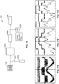
- Figure 11A provides an illustration of traction motor current at low speed
- Figure 11B provides an illustration of traction motor current at intermediate speed
- Figure 11C provides an illustration of traction motor current at high speed. As seen in Figures 11B and 11C , as speed increases, the signal becomes generally sinusoidal with relatively large harmonics.
- sensor power may be selectively directed to the sensor(s), e.g., at one or more predetermined frequency or range of frequencies.
- a fundamental portion of the signal may be utilized, while in other embodiments only harmonics may be utilized (e.g., switching frequency, or a specific harmonic such as a 5 th harmonic).
- the total current may be utilized, or a band of frequencies (e.g., 400-1000Hz).
- Figures 11A, 11B, 11C show a 3 phase AC motor, a DC motor with a chopper ripple or another motor, such as one which has current variation, may be used in other embodiments.
- the senor receives sensor power in various embodiments from a wire or cable from the sensor transformer.
- the sensor acquires information, and in various embodiments transmits the acquired information to a remote recipient.
- the sensor in various embodiments is located on a drive assembly of a vehicle and it transmits acquired or detected information to a cab of a vehicle.
- the sensor may receive information or commands from the remote location (e.g., vehicle of cab).
- the senor may wirelessly communicate with a remote source. For example, using sensor power provided by the sensor transformer, the sensor may transmit information.
- the sensor wirelessly communicates with a remote source (e.g., cab of vehicle) via a wireless receiver 150.
- the sensor may be disposed proximate to the AC power component.
- the wireless receiver may be communicatively coupled to the sensor and mounted, for example, to a drive assembly (e.g., drive assembly).
- the wireless receiver may not be employed.
- the sensor may communicate with a remote location using a wired connection 152.
- the wired connection for example, may be a speed sensor cable of a traction motor assembly, with the sensor able to transmit over the speed sensor cable.
- Other types of sensor cables may be utilized in alternate embodiments based in part on the end use parameters.
- each AC power component in various embodiments has one or more corresponding sensor transformers (and, in turn, one or more corresponding sensors).
- the system may (e.g., have a processing unit configured to) identify a particular one of the AC power components based on a signature frequency of the particular AC power component. For example, each AC power component may operate at a particular frequency (or range) unique to it in comparison to the other AC power components.
- the system may include a controller that can identify a particular AC power component based on a selective provision of power to the particular AC power component. For example, motive power may be provided to only one AC power component (or select AC power components) at a particular time. Using the identified AC power component, the system may then identify which sensor information being received is associated with which particular AC power component.
- a controller communicates with at least one sensor transformer and one sensor.
- the controller may communicate with plural sensor transformers, plural sensors, or both.
- the controller further may communicate with a vehicle controller.
- Various sensor transformers may provide sensor power when voltages are passed through their respective cables. Whether it is charging energy storage devices (for powering sensors) or directly powering sensors, not all cables may be inducing sensor power generation in the sensor transformers all of the time.
- the controller may selectively route sensor power generated by one of a plurality of sensor transformers to one or more sensors.
- Which sensors, and which communication devices to transmit data back, may be programmed into the controller, and that selection may be made, in one example, based at least in part on which cables are transmitting current (and thus which sensor transformers are generating sensor power).
- the controller may even influence a vehicle controller based at least in part on the sensor readings themselves, which sensor transformers are generating sensor power, and/or how much power the sensor transformers are providing.
- the amount of sensor power the sensor transformer may generate can be influenced by the nature and amount of current passing through its respective cable.
- Figure 12 illustrates a flowchart of a method 1200 (e.g., a method for providing sensor power to a sensor).
- the operations of Figure 12 may be implemented by a controller having one or more processors executing program instructions stored in memory.
- the method may employ structures or aspects of various embodiments (e.g., systems and/or methods) discussed herein, such as the system.
- certain steps (or operations) may be omitted or added, certain steps may be combined, certain steps may be performed simultaneously, certain steps may be performed concurrently, certain steps may be split into multiple steps, certain steps may be performed in a different order, or certain steps or series of steps may be re-performed in an iterative fashion.
- portions, aspects, and/or variations of the method may be used as one or more algorithms to direct hardware to perform one or more operations described herein. Other methods may be used in accordance with embodiments herein.
- current is conducted to an AC power component (e.g., traction motor) via a cable.
- the current may be an operational current provided to the AC power component in connection with utilization of the AC power component to perform a desired task or mission.
- a sensor power signal is generated.
- the sensor power signal is generated using a sensor transformer, with the sensor power signal generated responsive to the current conducted to the AC component via the cable.
- the sensor transformer may include a coil disposed proximate (e.g., surrounding or alongside) the cable, with the coil generating an induced voltage responsive to current passing through the cable. All or a portion of the current cable may be utilized to generate the sensor power signal.
- a harmonic portion of the current is utilized to generate the sensor power signal.
- the power sensor signal is transmitted to a sensor.
- the signal may be processed or modified before reception by the sensor.
- the sensor power signal is filtered.
- the signal is filtered with a band pass filter that is interposed between the sensor transformer and the sensor.
- excess current of the sensor power signal may be dissipated.
- a load element coupled to the sensor transformer may be utilized to dissipate the excess current.
- energy from the sensor power signal is stored. The energy may be stored by a capacitor coupled to the sensor.
- information is obtained by the sensor.
- the information corresponds to operation of the AC power component.
- the AC power component is a traction motor
- the sensed information may include temperature and/or fluid levels associated with one or more bearings.
- the information acquired with the sensor may be transmitted to a remote processor or other recipient (e.g., located in the cab of a vehicle) either wirelessly or via a wired connection.
- a remote processor or other recipient e.g., located in the cab of a vehicle
- sensor information is communicated wirelessly (e.g., via a wireless receiver disposed proximate the sensor) with a remote source.
- sensor information is communicated via a speed sensor cable.
- the received information is utilized to help operate the AC power component.
- properties or conditions detected by the sensor may be used to monitor the performance of the AC power component and make appropriate adjustments to the operation of the AC power component.
- a particular AC power component corresponding to a given sensor may be identified using a signature frequency and/or selective operation of the AC power component as discussed herein.
- a system may include an alternating current (AC) power component, a cable, a sensor transformer, and a sensor.
- the cable is coupled to the AC power component, and can conduct current to the AC power component.
- the sensor transformer may include a coil disposed proximate to the cable and generating an induced voltage responsive to conduction of the current through the cable.
- the sensor is coupled to the sensor transformer and receives sensor power from the sensor transformer. The sensor can obtain information corresponding to operation of the AC power component.
- the AC power component is disposed on a vehicle.
- the AC power component may be a traction motor of the vehicle.
- the traction motor may be part of a drive assembly including the traction motor and a truck, with the sensor transformer and sensor mounted to the drive assembly.
- the sensor transformer defines an opening through which the cable passes.
- the sensor transformer may be a split-core transformer.
- the sensor transformer includes a coil disposed proximate the cable, and the cable does not pass through the coil.
- the system further includes a band pass filter interposed between the sensor transformer and the sensor.
- the system further includes a storage element coupled to the sensor.
- the system further includes a rectifier interposed between the sensor transformer and the sensor.
- the system can use a harmonic portion of the current passing through the cable.
- the system includes a plurality of AC power components having associated corresponding sensor transformers, and can identify a particular AC power component based on a selective provision of power to the particular AC power component.
- the system includes a plurality of AC power components having associated corresponding sensor transformers, and can identify a particular AC power component based on a signature frequency of the particular AC power component.
- the senor is configured to wirelessly communicate with a remote source
- the senor is configured to communicate with a remote source via a speed sensor cable.
- a method may include conducting current to an alternating current (AC) power component via a cable.
- the method may include generating a sensor power signal with a sensor transformer responsive to the current conducted to the AC power component via the cable. Further, the method may include transmitting the sensor power signal to a sensor. The method may include obtaining information corresponding to operation of the AC power component with the sensor.
- AC alternating current
- the method may include filtering the sensor power signal with a band pass filter interposed between the sensor transformer and the sensor.
- the method may include dissipating excess current of the sensor power signal with a load element coupled to the sensor transformer.
- the method may include storing energy from the sensor power signal with a storage element coupled to the sensor.
- the method may include using a harmonic portion of the current provided to the AC power component to generate the sensor power signal.
- a system may include a plurality of AC power components having associated corresponding sensor transformers, and the method may include identifying a particular AC power component based on a selective provision of power to the particular AC power component.
- a system may include a plurality of AC power components having associated corresponding sensor transformers, and the method may include identifying a particular AC power component based on a signature frequency of the particular AC power component.
- the method may include wirelessly communicating information between the sensor and a remote source via a wireless receiver disposed proximate the AC power component.
- the method may include communicating information between the sensor and a remote source via a speed sensor cable.
- a system may include a drive assembly, a cable, a sensor transformer, and a sensor.
- the drive assembly may include a traction motor.
- the cable is coupled to the traction motor and can conduct current to the traction motor.
- the sensor transformer may include a coil disposed proximate to the cable. The coil generates an induced voltage responsive to conduction of the current through the cable.
- the sensor transformer is mounted to the drive assembly proximate the cable.
- the sensor is coupled to the sensor transformer and receives power from the sensor transformer.
- the sensor is mounted to the drive assembly and can obtain information corresponding to operation of the drive assembly.
- processors and “computer,” and related terms, e.g., “processing device,” “computing device,” and “controller,” may be not limited to just those integrated circuits referred to in the art as a computer, but refer to a microcontroller, a microcomputer, a programmable logic controller (PLC), field programmable gate array, and application specific integrated circuit, and other programmable circuits.
- PLC programmable logic controller
- Processors, computer, and controllers discussed herein include memory (e.g., a tangible and non-transitory memory) in various embodiments. Suitable memory may include, for example, a computer-readable medium.
- a computer-readable medium may be, for example, a random-access memory (RAM), a computer-readable non-volatile medium, such as a flash memory.
- RAM random-access memory
- non-transitory computer-readable media represents a tangible computer-based device implemented for short-term and long-term storage of information, such as, computer-readable instructions, data structures, program modules and sub-modules, or other data in any device. Therefore, processes or activities described herein may be encoded as executable instructions embodied in a tangible, non-transitory, computer-readable medium, including, without limitation, a storage device and/or a memory device. Such instructions, when executed by a processor, cause the processor to perform at least a portion of the methods described herein.
- tangible, computer-readable media including, without limitation, non-transitory computer storage devices, including without limitation, volatile and non-volatile media, and removable and non-removable media such as firmware, physical and virtual storage, CD-ROMS, DVDs, and other digital sources, such as a network or the Internet.
Landscapes
- Engineering & Computer Science (AREA)
- Computer Networks & Wireless Communication (AREA)
- Power Engineering (AREA)
- Physics & Mathematics (AREA)
- General Physics & Mathematics (AREA)
- Mechanical Engineering (AREA)
- Electric Propulsion And Braking For Vehicles (AREA)
- Inverter Devices (AREA)
Abstract
Description
- This application claims priority to
U.S. Provisional Application No. 63/031,450 - The subject matter described relates to systems and methods for use in providing power to sensors, for example sensors of a vehicle.
- Alternating current (AC) power components may be used in a variety of applications. For example, AC traction motors may be used in connection with vehicle propulsion. Such components may have a number of sensors associated with them. Providing power to sensors in such applications may encounter a number of challenges. For example, if power is provided to individual sensors via cables from a remote source, the associated cables may be expensive, and difficult to route. Such cables may result in increased complexity and expense of assembling and maintaining systems (e.g., vehicles). If batteries are used, the batteries may provide undesirable additional weight. For example, in vehicle applications, the extra weight of batteries may result in additional wear on related components. Further, in order to preserve battery life, information from sensors may be provided intermittently, resulting in periods of time where sensor information is not known. These batteries also need periodic replacement and have performance impact based on ambient conditions. It may be desirable to have systems and methods that differ from those that are currently available.
- In one embodiment, a system may include an alternating current (AC) power component, a cable, a sensor transformer, and a sensor. The cable is coupled to the AC power component and can conduct current to the AC power component. The sensor transformer may include a coil disposed proximate to the cable. The coil generates an induced voltage responsive to conduction of the current through the cable. The sensor is coupled to the sensor transformer and receives sensor power from the sensor transformer. The sensor obtains information corresponding to operation of the AC power component.
- In one embodiment, a method may include conducting current to an alternating current (AC) power component via a cable. The method may include generating a sensor power signal with a sensor transformer responsive to the current conducted to the AC power component via the cable. Further, the method may include transmitting the sensor power signal to a sensor. The method may include obtaining information corresponding to operation of the AC power component with the sensor.
- In one embodiment, a system may include a drive assembly, a cable, a sensor transformer, and a sensor. The drive assembly may include a traction motor. The cable is coupled to the traction motor and can conduct current to the traction motor. The sensor transformer may include a coil disposed proximate to the cable. The coil generates an induced voltage responsive to conduction of the current through the cable. The sensor transformer is mounted to the drive assembly proximate the cable. The sensor is coupled to the sensor transformer and receives power from the sensor transformer. The sensor is mounted to the drive assembly and can obtain information corresponding to operation of the drive assembly.
- The inventive subject matter may be understood from reading the following description of non-limiting embodiments, with reference to the attached drawings, wherein below:
-
Figure 1 illustrates a block schematic diagram of a system; -
Figure 2 provides a schematic view of a vehicle; -
Figure 3 provides a perspective view of a motor assembly; -
Figure 4 provides a perspective view of a drive assembly that includes the motor assembly ofFigure 3 ; -
Figure 5 provides a sectional view of the motor assembly ofFigure 3 ; -
Figure 6 provides a perspective view of an example cable that passes through a cleat; -
Figure 7 provides a perspective view of an example coil that has an opening through which a cable passes; -
Figure 8 provides a perspective view of another example coil that has an opening through which the cable passes; -
Figure 9 illustrates an example coil through which the cable does not pass; -
Figure 10 provides an electrical schematic view of an example system; -
Figure 11A provides an illustration of traction motor current at low speed; -
Figure 11B provides an illustration of traction motor current at intermediate speed; -
Figure 11C provides an illustration of traction motor current at high speed; and -
Figure 12 illustrates a flowchart of a method. - Embodiments of the subject matter described herein relate to systems and methods for providing power to sensors. For example, various embodiments relate to the use of a sensor transformer located proximate to a corresponding sensor and providing power to the sensor. The sensor transformer in various embodiments is disposed proximate a cable of an AC power component, and generates an induced voltage responsive to power running through the cable. In some embodiments, the power for a sensor may be generated relatively close to the sensor, without the need for lengthy, costly, and complex wiring runs and/or may reduce or eliminate undesirable weight and/or longevity issues associated with solar panels, batteries, or other energy storage devices.
- While various examples herein may be discussed in connection with rail vehicles, not all embodiments described herein relate to rail vehicle systems. Suitable vehicles may include automobiles, trucks, buses, mining vehicles, marine vessels, aircraft, agricultural vehicles, and the like. And, while embodiments of the invention may be applied to stationary applications, most stationary applications do not have the same constraints and challenges associated with vehicles such that the heavy battery systems, and grid connectivity may be more appropriate.
-
Figure 1 illustrates a schematic diagram of asystem 100. The depictedsystem 100 may include an alternating current (AC)power component 110, acable 120, asensor transformer 130, and asensor 140. The cable is coupled to the AC power component, and provides current to the AC power component. In various embodiments, the sensor transformer may generate a voltage responsive to current moving through the cable, and thereby may provide power to the sensor. - The sensor transformer may include a
coil 132. While the coil is represented as a single block inFigure 1 , multiple coils may be used in various embodiments. The coil may be disposed proximate the cable and may generate an induced voltage responsive to conduction of current through the cable. With regard to distances between the cable and the sensor transformer, the sensor transformer in various embodiments may be located within a few centimeters or less of the cable. The sensor transformer in various embodiments may be mounted on or near the AC power component (or an assembly including the AC power component) and relatively close to the sensor. A suitable sensor transformer may be a device used to acquire, generate, or receive sensor power to be transferred to the sensor, and may be selected based at least in part on application specific criteria. - In one embodiment, the sensor may be coupled to the sensor transformer (e.g., via a wire or cable) and may receive sensor power from the sensor transformer. The sensor may be mounted relatively near the sensor transformer. For example, the sensor may be within 10-20 feet of the sensor transformer in various embodiments. The sensor can obtain information corresponding to operation of the AC power component. With the proper sensor selection, the sensor may detect one or more of temperature, fluid level, vibration, or frequency content of a signal, among others. This may be done while providing sensor power to the sensor. Information corresponding to operation of the AC power component may include information regarding related components. For example, in embodiments where the AC power component is a traction motor, information corresponding to operation of the traction motor may include information regarding associated axles, gears, bearings, and the like. For example, information corresponding to operation of a traction motor may include gear case oil level, information regarding operation of motor bearings, etc.
- While one block is used to represent sensor in
Figure 1 , multiple sensors may be used in various embodiments. Each sensor may have a dedicated sensor transformer, or one sensor transformer may provide sensor power to multiple sensors, depending on conditions of a particular application, for example amounts of sensor power required, locations available for sensor transformers, and distance and routing options between transformers and sensors. - In various embodiments, the AC power component may be disposed on a vehicle.
Figure 2 provides a schematic view of an example system in which an AC power component may be disposed on avehicle 205. The vehicle in the illustrated embodiment is a rail vehicle (e.g., locomotive). The AC power component is atraction motor 210. As seen inFigure 2 , the depicted traction motor is part of adrive assembly 220. The sensor transformer and the sensor are both mounted to the drive assembly. - In one embodiment, the drive assembly may include
multiple traction motors 210. For example,Figure 3 provides a perspective view of amotor assembly 300 that may include the traction motor andwheels 310.Figure 4 provides a perspective view of a drive assembly that may include atruck 230 and three motor assemblies. In various embodiments, a sensor transformer mounted to one motor assembly may provide sensor power to plural sensors on one or more other motor assemblies of the truck. - Sensors may be placed at or near various locations of the drive assembly to detect various properties (e.g., temperature, fluid level, vibration) associated with one or more components or aspects of the drive assembly. For example,
Figure 5 provides a sectional view of the motor assembly. The motor assembly may include various bearings - a motor non-pinion end rolling element bearing 510, a motor pinion end rolling element bearing 520, axle rollingelement bearing locations 530, and U tube rollingelement bearings 540. The motor assembly may include agear case 550 and associated gears. Sensors may be disposed proximate to corresponding bearing locations, gears, and/or the gear case to detect one or more properties or conditions associated with the bearings, gears, and/or the gear case. - As discussed herein, the sensor transformer is located proximate to the cable (e.g., close enough to the cable to generate a sufficient amount of sensor power for the sensor). The amount of sensor power required for sensor operation may be very small relative to the higher current and power utilized by the AC power component, so that the providing of sensor power to the sensor via the sensor transformer does not have a meaningful effect on operation of the AC power component. For example, traction motors can have power ratings of more than 100 kiloWatts whereas sensor requirements may be several milliwatts. In various embodiments, the sensor transformer may be mounted to a component or device that secures and/or routes the cable. For example,
Figure 6 provides a perspective view of an example cable that passes through acleat 600. The cleat, for example, may be mounted to a drive assembly (e.g., drive assembly). As seen in the depicted example ofFigure 6 , the sensor transformer is mounted to the cleat. In some embodiments, the sensor transformer may form the cable cleat. A three cable system is shown inFigure 6 , but, in other embodiments a single cable (or any other number of cable) system may be employed. - Various coil arrangements may be employed by sensor transformers in various embodiments. For example, in some embodiments, the sensor transformer defines an
opening 134 through which the cable passes.Figure 7 provides a perspective view of an example coil that has an opening through which the cable passes.Figure 8 provides a perspective view of another example coil that has an opening through which the cable passes. The example coils ofFigures 7 and 8 are both examples of split-coretransformers having gaps 135 between core portions. In other embodiments, a solid core transformer having an opening may be employed. - In still other embodiments, the cable may not pass through the coil. For example,
Figure 9 illustrates an example coil that is disposed near a cable, but the cable does not pass through the coil. -
Figure 10 provides an electrical schematic view of aspects of an example system showing connections between the sensor transformer, sensor, and various components. As seen in the illustrated example, the system may include aband pass filter 1010 that is interposed between the sensor transformer and the sensor. Current from the sensor transformer to the sensor is first filtered by the band pass filter, so that only current at selected frequencies is provided to the sensor. - As seen in
Figure 10 , the system may include aload element 1020. Theload element 1020 may be coupled to the sensor transformer (e.g., via switch 1021), and can dissipate excess current or voltage (e.g., current in excess of a rating of the sensor, or current when an energy storage device selectively coupled to the sensor is full or above a threshold value). For example, when current is not required or desired for the sensor, the switch may be closed to allow current to flow from the sensor transformer to the load element. However, when current is desired for the sensor, the switch may be opened to prevent current from being directed to the load element. - The depicted example system of
Figure 10 may include astorage element 1030. The storage element in various embodiments may be a capacitor, or, as another example, a battery. The storage element may be coupled to the sensor. When current from the sensor transformer is available, the storage element may be charged, and when current from the sensor transformer is not available, the storage element may be used to provide sensor power to the sensor. For example, in a first state of operation of the AC power component when sensor power from the sensor coil is readily available, the storage element may be charged, with the stored energy later used for the sensor at a time when sensor power is not being derived from the AC power component and therefore is not as readily available. In one embodiment, the storage element may store sufficient energy for a relatively short amount of time (e.g., 8 hours), allowing for a relatively small and lightweight capacitor (e.g., relative to larger, heavier storage devices such as batteries which may provide power for relatively long time periods such as months and years) to be utilized for storage. - Further, the depicted example system of
Figure 10 may include arectifier 1040. The rectifier may be interposed between the sensor transformer and the sensor, and converts alternating current from the sensor transformer to a direct current provided to the sensor. The load element and switch can be placed in other suitable locations as well in various embodiments, for example after the filter or at the output of the rectifier. - As mentioned above, current from the sensor transformer to the sensor may be provided at selected frequencies (e.g., via band pass filter). For example, in some embodiments, the system may use a harmonic portion of the current passing through the cable. The harmonic frequency (or other desired frequency) may be selected (e.g., via band pass filter) so that sensor is provided current during a desired state of operation to limit intrusiveness on operation, with power for the sensor being stored in a capacitor until desired state of operation is reached again.
Figure 11A provides an illustration of traction motor current at low speed,Figure 11B provides an illustration of traction motor current at intermediate speed, andFigure 11C provides an illustration of traction motor current at high speed. As seen inFigures 11B and 11C , as speed increases, the signal becomes generally sinusoidal with relatively large harmonics. As the current for a traction motor may be thousands of amps, and a sensor may require a relatively small number of milliamps, it is possible to divert enough power from the traction motor to power one or more sensors without meaningful effect on the traction motor. Further, as discussed herein, sensor power may be selectively directed to the sensor(s), e.g., at one or more predetermined frequency or range of frequencies. For example, in various embodiments, a fundamental portion of the signal may be utilized, while in other embodiments only harmonics may be utilized (e.g., switching frequency, or a specific harmonic such as a 5th harmonic). In other embodiments, the total current may be utilized, or a band of frequencies (e.g., 400-1000Hz). WhileFigures 11A, 11B, 11C show a 3 phase AC motor, a DC motor with a chopper ripple or another motor, such as one which has current variation, may be used in other embodiments. - With reference to
Figure 1 , the sensor receives sensor power in various embodiments from a wire or cable from the sensor transformer. The sensor acquires information, and in various embodiments transmits the acquired information to a remote recipient. For example, the sensor in various embodiments is located on a drive assembly of a vehicle and it transmits acquired or detected information to a cab of a vehicle. The sensor may receive information or commands from the remote location (e.g., vehicle of cab). - In some embodiments, the sensor may wirelessly communicate with a remote source. For example, using sensor power provided by the sensor transformer, the sensor may transmit information. In the illustrated example of
Figure 1 , the sensor wirelessly communicates with a remote source (e.g., cab of vehicle) via awireless receiver 150. The sensor may be disposed proximate to the AC power component. For example, the wireless receiver may be communicatively coupled to the sensor and mounted, for example, to a drive assembly (e.g., drive assembly). - In other embodiments, the wireless receiver may not be employed. For example, as shown in
Figure 1 , the sensor may communicate with a remote location using awired connection 152. The wired connection, for example, may be a speed sensor cable of a traction motor assembly, with the sensor able to transmit over the speed sensor cable. Other types of sensor cables may be utilized in alternate embodiments based in part on the end use parameters. - In various embodiments multiple AC power components may be utilized. For example, multiple traction motors may be utilized. (See, e.g.,
Figure 4 and related discussion.) Each AC power component in various embodiments has one or more corresponding sensor transformers (and, in turn, one or more corresponding sensors). The system may (e.g., have a processing unit configured to) identify a particular one of the AC power components based on a signature frequency of the particular AC power component. For example, each AC power component may operate at a particular frequency (or range) unique to it in comparison to the other AC power components. Additionally or alternatively, the system may include a controller that can identify a particular AC power component based on a selective provision of power to the particular AC power component. For example, motive power may be provided to only one AC power component (or select AC power components) at a particular time. Using the identified AC power component, the system may then identify which sensor information being received is associated with which particular AC power component. - In one embodiment, a controller is provided that communicates with at least one sensor transformer and one sensor. In one embodiment, the controller may communicate with plural sensor transformers, plural sensors, or both. The controller further may communicate with a vehicle controller. Various sensor transformers may provide sensor power when voltages are passed through their respective cables. Whether it is charging energy storage devices (for powering sensors) or directly powering sensors, not all cables may be inducing sensor power generation in the sensor transformers all of the time. As such, the controller may selectively route sensor power generated by one of a plurality of sensor transformers to one or more sensors. Which sensors, and which communication devices to transmit data back, may be programmed into the controller, and that selection may be made, in one example, based at least in part on which cables are transmitting current (and thus which sensor transformers are generating sensor power). In one embodiment, the controller may even influence a vehicle controller based at least in part on the sensor readings themselves, which sensor transformers are generating sensor power, and/or how much power the sensor transformers are providing. Naturally, the amount of sensor power the sensor transformer may generate can be influenced by the nature and amount of current passing through its respective cable.
-
Figure 12 illustrates a flowchart of a method 1200 (e.g., a method for providing sensor power to a sensor). The operations ofFigure 12 may be implemented by a controller having one or more processors executing program instructions stored in memory. The method, for example, may employ structures or aspects of various embodiments (e.g., systems and/or methods) discussed herein, such as the system. In various embodiments, certain steps (or operations) may be omitted or added, certain steps may be combined, certain steps may be performed simultaneously, certain steps may be performed concurrently, certain steps may be split into multiple steps, certain steps may be performed in a different order, or certain steps or series of steps may be re-performed in an iterative fashion. In various embodiments, portions, aspects, and/or variations of the method may be used as one or more algorithms to direct hardware to perform one or more operations described herein. Other methods may be used in accordance with embodiments herein. - At
step 1202, current is conducted to an AC power component (e.g., traction motor) via a cable. The current may be an operational current provided to the AC power component in connection with utilization of the AC power component to perform a desired task or mission. - At
step 1204, a sensor power signal is generated. In the illustrated embodiments, the sensor power signal is generated using a sensor transformer, with the sensor power signal generated responsive to the current conducted to the AC component via the cable. In various embodiments, the sensor transformer may include a coil disposed proximate (e.g., surrounding or alongside) the cable, with the coil generating an induced voltage responsive to current passing through the cable. All or a portion of the current cable may be utilized to generate the sensor power signal. In the illustrated example, atstep 1216, a harmonic portion of the current is utilized to generate the sensor power signal. - At
step 1206, the power sensor signal is transmitted to a sensor. The signal may be processed or modified before reception by the sensor. For example, atstep 1210, the sensor power signal is filtered. In various embodiments, the signal is filtered with a band pass filter that is interposed between the sensor transformer and the sensor. As another example, atstep 1212, excess current of the sensor power signal may be dissipated. As discussed herein, a load element coupled to the sensor transformer may be utilized to dissipate the excess current. Further, atstep 1214 of the illustrated example, energy from the sensor power signal is stored. The energy may be stored by a capacitor coupled to the sensor. - At
step 1208, information is obtained by the sensor. The information corresponds to operation of the AC power component. For example, in some embodiments the AC power component is a traction motor, and the sensed information may include temperature and/or fluid levels associated with one or more bearings. - The information acquired with the sensor may be transmitted to a remote processor or other recipient (e.g., located in the cab of a vehicle) either wirelessly or via a wired connection. For example, at 1218, sensor information is communicated wirelessly (e.g., via a wireless receiver disposed proximate the sensor) with a remote source. As another example, at
step 1220, sensor information is communicated via a speed sensor cable. - At
step 1222, the received information is utilized to help operate the AC power component. For example, properties or conditions detected by the sensor may be used to monitor the performance of the AC power component and make appropriate adjustments to the operation of the AC power component. In embodiments utilizing multiple AC power components, a particular AC power component corresponding to a given sensor may be identified using a signature frequency and/or selective operation of the AC power component as discussed herein. - In one embodiment, a system may include an alternating current (AC) power component, a cable, a sensor transformer, and a sensor. The cable is coupled to the AC power component, and can conduct current to the AC power component. The sensor transformer may include a coil disposed proximate to the cable and generating an induced voltage responsive to conduction of the current through the cable. The sensor is coupled to the sensor transformer and receives sensor power from the sensor transformer. The sensor can obtain information corresponding to operation of the AC power component.
- Optionally, the AC power component is disposed on a vehicle. For example, the AC power component may be a traction motor of the vehicle. For instance, the traction motor may be part of a drive assembly including the traction motor and a truck, with the sensor transformer and sensor mounted to the drive assembly.
- Optionally, the sensor transformer defines an opening through which the cable passes. For example, the sensor transformer may be a split-core transformer.
- Optionally, the sensor transformer includes a coil disposed proximate the cable, and the cable does not pass through the coil.
- Optionally, the system further includes a band pass filter interposed between the sensor transformer and the sensor.
- Optionally, the system further includes a storage element coupled to the sensor.
- Optionally, the system further includes a rectifier interposed between the sensor transformer and the sensor.
- Optionally, the system can use a harmonic portion of the current passing through the cable.
- Optionally, the system includes a plurality of AC power components having associated corresponding sensor transformers, and can identify a particular AC power component based on a selective provision of power to the particular AC power component.
- Optionally, the system includes a plurality of AC power components having associated corresponding sensor transformers, and can identify a particular AC power component based on a signature frequency of the particular AC power component.
- Optionally, the sensor is configured to wirelessly communicate with a remote source,
- Optionally, the sensor is configured to communicate with a remote source via a speed sensor cable.
- In one embodiment, a method may include conducting current to an alternating current (AC) power component via a cable. The method may include generating a sensor power signal with a sensor transformer responsive to the current conducted to the AC power component via the cable. Further, the method may include transmitting the sensor power signal to a sensor. The method may include obtaining information corresponding to operation of the AC power component with the sensor.
- Optionally, the method may include filtering the sensor power signal with a band pass filter interposed between the sensor transformer and the sensor.
- Optionally, the method may include dissipating excess current of the sensor power signal with a load element coupled to the sensor transformer.
- Optionally, the method may include storing energy from the sensor power signal with a storage element coupled to the sensor.
- Optionally, the method may include using a harmonic portion of the current provided to the AC power component to generate the sensor power signal.
- Optionally, a system may include a plurality of AC power components having associated corresponding sensor transformers, and the method may include identifying a particular AC power component based on a selective provision of power to the particular AC power component.
- Optionally, a system may include a plurality of AC power components having associated corresponding sensor transformers, and the method may include identifying a particular AC power component based on a signature frequency of the particular AC power component.
- Optionally, the method may include wirelessly communicating information between the sensor and a remote source via a wireless receiver disposed proximate the AC power component.
- Optionally, the method may include communicating information between the sensor and a remote source via a speed sensor cable.
- In one embodiment, a system may include a drive assembly, a cable, a sensor transformer, and a sensor. The drive assembly may include a traction motor. The cable is coupled to the traction motor and can conduct current to the traction motor. The sensor transformer may include a coil disposed proximate to the cable. The coil generates an induced voltage responsive to conduction of the current through the cable. The sensor transformer is mounted to the drive assembly proximate the cable. The sensor is coupled to the sensor transformer and receives power from the sensor transformer. The sensor is mounted to the drive assembly and can obtain information corresponding to operation of the drive assembly.
- As used herein, the terms "processor" and "computer," and related terms, e.g., "processing device," "computing device," and "controller," may be not limited to just those integrated circuits referred to in the art as a computer, but refer to a microcontroller, a microcomputer, a programmable logic controller (PLC), field programmable gate array, and application specific integrated circuit, and other programmable circuits. Processors, computer, and controllers discussed herein include memory (e.g., a tangible and non-transitory memory) in various embodiments. Suitable memory may include, for example, a computer-readable medium. A computer-readable medium may be, for example, a random-access memory (RAM), a computer-readable non-volatile medium, such as a flash memory. The term "non-transitory computer-readable media" represents a tangible computer-based device implemented for short-term and long-term storage of information, such as, computer-readable instructions, data structures, program modules and sub-modules, or other data in any device. Therefore, processes or activities described herein may be encoded as executable instructions embodied in a tangible, non-transitory, computer-readable medium, including, without limitation, a storage device and/or a memory device. Such instructions, when executed by a processor, cause the processor to perform at least a portion of the methods described herein. As such, the term includes tangible, computer-readable media, including, without limitation, non-transitory computer storage devices, including without limitation, volatile and non-volatile media, and removable and non-removable media such as firmware, physical and virtual storage, CD-ROMS, DVDs, and other digital sources, such as a network or the Internet.
- The singular forms "a", "an", and "the" include plural references unless the context clearly dictates otherwise. "Optional" or "optionally" means that the subsequently described event or circumstance may or may not occur, and that the description may include instances where the event occurs and instances where it does not. Approximating language, as used herein throughout the specification and claims, may be applied to modify any quantitative representation that could permissibly vary without resulting in a change in the basic function to which it may be related. Accordingly, a value modified by a term or terms, such as "about," "substantially," and "approximately," may be not to be limited to the precise value specified. In at least some instances, the approximating language may correspond to the precision of an instrument for measuring the value. Here and throughout the specification and claims, range limitations may be combined and/or interchanged, such ranges may be identified and include all the sub-ranges contained therein unless context or language indicates otherwise.
- This written description uses examples to disclose the embodiments, including the best mode, and to enable a person of ordinary skill in the art to practice the embodiments, including making and using any devices or systems and performing any incorporated methods. The claims define the patentable scope of the disclosure, and include other examples that occur to those of ordinary skill in the art. Such other examples are intended to be within the scope of the claims if they have structural elements that do not differ from the literal language of the claims, or if they include equivalent structural elements with insubstantial differences from the literal language of the claims.
Claims (13)
Applications Claiming Priority (2)
| Application Number | Priority Date | Filing Date | Title |
|---|---|---|---|
| US202063031450P | 2020-05-28 | 2020-05-28 | |
| US17/231,865 US11752958B2 (en) | 2020-05-28 | 2021-04-15 | Systems and methods for providing power to sensors |
Publications (1)
| Publication Number | Publication Date |
|---|---|
| EP3916958A1 true EP3916958A1 (en) | 2021-12-01 |
Family
ID=76355220
Family Applications (1)
| Application Number | Title | Priority Date | Filing Date |
|---|---|---|---|
| EP21174313.3A Pending EP3916958A1 (en) | 2020-05-28 | 2021-05-18 | Systems and methods for providing sensor power |
Country Status (4)
| Country | Link |
|---|---|
| US (1) | US11752958B2 (en) |
| EP (1) | EP3916958A1 (en) |
| CN (1) | CN113746209B (en) |
| AU (1) | AU2021202998B2 (en) |
Cited By (2)
| Publication number | Priority date | Publication date | Assignee | Title |
|---|---|---|---|---|
| DE102022207010A1 (en) * | 2022-07-08 | 2024-01-11 | Zf Friedrichshafen Ag | Holding device for holding at least one electrically conductive connecting means and providing electrical supply energy for an electrical component for a vehicle that can be arranged in or on the holding device, holding system and method for operating a holding device |
| DE102022207008A1 (en) * | 2022-07-08 | 2024-01-11 | Zf Friedrichshafen Ag | Holding device for holding at least one electrically conductive connecting means and providing electrical supply energy for an electrical component for a vehicle that can be arranged outside the holding device, holding system and method for operating a holding device |
Citations (4)
| Publication number | Priority date | Publication date | Assignee | Title |
|---|---|---|---|---|
| US20090015196A1 (en) * | 2007-05-15 | 2009-01-15 | Azima, Inc. | Power Supply for Sensors and Other Electronic Devices |
| US20100253318A1 (en) * | 2009-02-02 | 2010-10-07 | Thomas Sr Kirk | High voltage to low voltage inductive power supply with current sensor |
| US10379559B1 (en) * | 2015-09-30 | 2019-08-13 | Alarm.Com Incorporated | Monitoring of electrical appliances based on dispersion of impedance |
| US20200070906A1 (en) * | 2018-08-30 | 2020-03-05 | Camso Inc. | Systems and methods for monitoring vehicles |
Family Cites Families (12)
| Publication number | Priority date | Publication date | Assignee | Title |
|---|---|---|---|---|
| US10018613B2 (en) | 2006-11-16 | 2018-07-10 | General Electric Company | Sensing system and method for analyzing a fluid at an industrial site |
| WO2008149447A1 (en) | 2007-06-07 | 2008-12-11 | Mitsubishi Electric Corporation | Electric motor controller |
| JP5575040B2 (en) | 2011-03-31 | 2014-08-20 | 富士重工業株式会社 | Charging system |
| GB201121938D0 (en) | 2011-12-21 | 2012-02-01 | Dames Andrew N | Supply of grid power to moving vehicles |
| US9067500B2 (en) | 2012-05-21 | 2015-06-30 | Krassimire Mihaylov Penev | Self rechargeable synergy drive for a motor vehicle |
| US10063105B2 (en) | 2013-07-11 | 2018-08-28 | Energous Corporation | Proximity transmitters for wireless power charging systems |
| US9079503B2 (en) * | 2012-09-06 | 2015-07-14 | General Electric Company | Systems and methods for generating power in a vehicle |
| US9206684B2 (en) * | 2012-11-01 | 2015-12-08 | Schlumberger Technology Corporation | Artificial lift equipment power line communication |
| US9054621B2 (en) * | 2013-04-23 | 2015-06-09 | Rockwell Automation Technologies, Inc. | Position sensorless open loop control for motor drives with output filter and transformer |
| JP6149575B2 (en) * | 2013-07-29 | 2017-06-21 | 三菱自動車工業株式会社 | Vehicle warm-up control device |
| US11428755B2 (en) * | 2017-05-26 | 2022-08-30 | Allegro Microsystems, Llc | Coil actuated sensor with sensitivity detection |
| US11137421B1 (en) * | 2020-04-10 | 2021-10-05 | Schneider Electric USA, Inc. | Non-contact voltage sensing system |
-
2021
- 2021-04-15 US US17/231,865 patent/US11752958B2/en active Active
- 2021-05-12 AU AU2021202998A patent/AU2021202998B2/en active Active
- 2021-05-18 EP EP21174313.3A patent/EP3916958A1/en active Pending
- 2021-05-26 CN CN202110580380.0A patent/CN113746209B/en active Active
Patent Citations (4)
| Publication number | Priority date | Publication date | Assignee | Title |
|---|---|---|---|---|
| US20090015196A1 (en) * | 2007-05-15 | 2009-01-15 | Azima, Inc. | Power Supply for Sensors and Other Electronic Devices |
| US20100253318A1 (en) * | 2009-02-02 | 2010-10-07 | Thomas Sr Kirk | High voltage to low voltage inductive power supply with current sensor |
| US10379559B1 (en) * | 2015-09-30 | 2019-08-13 | Alarm.Com Incorporated | Monitoring of electrical appliances based on dispersion of impedance |
| US20200070906A1 (en) * | 2018-08-30 | 2020-03-05 | Camso Inc. | Systems and methods for monitoring vehicles |
Cited By (3)
| Publication number | Priority date | Publication date | Assignee | Title |
|---|---|---|---|---|
| DE102022207010A1 (en) * | 2022-07-08 | 2024-01-11 | Zf Friedrichshafen Ag | Holding device for holding at least one electrically conductive connecting means and providing electrical supply energy for an electrical component for a vehicle that can be arranged in or on the holding device, holding system and method for operating a holding device |
| DE102022207008A1 (en) * | 2022-07-08 | 2024-01-11 | Zf Friedrichshafen Ag | Holding device for holding at least one electrically conductive connecting means and providing electrical supply energy for an electrical component for a vehicle that can be arranged outside the holding device, holding system and method for operating a holding device |
| DE102022207008B4 (en) | 2022-07-08 | 2024-10-10 | Zf Friedrichshafen Ag | Holding system and method for operating a holding system |
Also Published As
| Publication number | Publication date |
|---|---|
| CN113746209A (en) | 2021-12-03 |
| US11752958B2 (en) | 2023-09-12 |
| CN113746209B (en) | 2024-12-17 |
| US20210370856A1 (en) | 2021-12-02 |
| AU2021202998A1 (en) | 2021-12-16 |
| AU2021202998B2 (en) | 2023-03-02 |
Similar Documents
| Publication | Publication Date | Title |
|---|---|---|
| KR102928335B1 (en) | Powering electric vehicles | |
| US12533968B2 (en) | Supercapacitor to electrochemical hybrid system with failsafe safety capability | |
| US20230211667A1 (en) | Supercapacitor system with a on board computing and charging capability | |
| US20230187954A1 (en) | Supercapacitor to electrochemical hybrid system | |
| US20250360835A1 (en) | System and method for energy management of a power pack for an electric vehicle including photovoltaic charging | |
| AU2021202998B2 (en) | Systems and methods for providing sensor power | |
| US20230216330A1 (en) | Supercapacitor and lead-acid battery hybrid battery with charging capability | |
| US8981721B2 (en) | Battery control device and electricity storage device | |
| US20230182621A1 (en) | System and method for analyzing temperature changes in supercapacitor battery storage for electric vehicle | |
| US20230234472A1 (en) | Supercapacitor to electrochemical hybrid system with a supercapacitor battery management capability | |
| US20230136195A1 (en) | Modular power pack energy storage unit | |
| AU2018202102B2 (en) | Systems and methods for generating power in a vehicle | |
| WO2023129521A1 (en) | Supercapacitor to electrochemical hybrid system with smart self discharge capability | |
| WO2015024946A1 (en) | High voltage interlock apparatus and method | |
| CN113039107A (en) | Electrification control system and method for electric vehicle | |
| CN105474455B (en) | Method for running secondary battery | |
| KR101635918B1 (en) | System for Preventing Risk From Occurring by Analyzing Vibration | |
| US20120169360A1 (en) | System and methods for testing electrical power system components | |
| CN112752671B (en) | Device and method for supplying energy to sensor devices in rail vehicles | |
| EP3640075A1 (en) | Railroad vehicle | |
| EA044855B1 (en) | SYSTEM AND METHOD FOR PROVIDING SENSOR POWER | |
| US20210270238A1 (en) | Rotary machine control system | |
| CN103101620A (en) | Heavy-load multi-rotor-wing unmanned helicopter | |
| Bastard | Some diagnostic and prognostic methods for components supporting electrical energy management in a military vehicle |
Legal Events
| Date | Code | Title | Description |
|---|---|---|---|
| PUAI | Public reference made under article 153(3) epc to a published international application that has entered the european phase |
Free format text: ORIGINAL CODE: 0009012 |
|
| STAA | Information on the status of an ep patent application or granted ep patent |
Free format text: STATUS: THE APPLICATION HAS BEEN PUBLISHED |
|
| AK | Designated contracting states |
Kind code of ref document: A1 Designated state(s): AL AT BE BG CH CY CZ DE DK EE ES FI FR GB GR HR HU IE IS IT LI LT LU LV MC MK MT NL NO PL PT RO RS SE SI SK SM TR |
|
| B565 | Issuance of search results under rule 164(2) epc |
Effective date: 20211019 |
|
| STAA | Information on the status of an ep patent application or granted ep patent |
Free format text: STATUS: REQUEST FOR EXAMINATION WAS MADE |
|
| 17P | Request for examination filed |
Effective date: 20220601 |
|
| P01 | Opt-out of the competence of the unified patent court (upc) registered |
Effective date: 20230530 |
|
| STAA | Information on the status of an ep patent application or granted ep patent |
Free format text: STATUS: EXAMINATION IS IN PROGRESS |
|
| 17Q | First examination report despatched |
Effective date: 20231025 |