EP3916938A2 - Modular floor box assembly - Google Patents
Modular floor box assembly Download PDFInfo
- Publication number
- EP3916938A2 EP3916938A2 EP21175868.5A EP21175868A EP3916938A2 EP 3916938 A2 EP3916938 A2 EP 3916938A2 EP 21175868 A EP21175868 A EP 21175868A EP 3916938 A2 EP3916938 A2 EP 3916938A2
- Authority
- EP
- European Patent Office
- Prior art keywords
- power
- deck
- housing
- floor box
- puck
- Prior art date
- Legal status (The legal status is an assumption and is not a legal conclusion. Google has not performed a legal analysis and makes no representation as to the accuracy of the status listed.)
- Pending
Links
Images




Classifications
-
- H—ELECTRICITY
- H02—GENERATION; CONVERSION OR DISTRIBUTION OF ELECTRIC POWER
- H02G—INSTALLATION OF ELECTRIC CABLES OR LINES, OR OF COMBINED OPTICAL AND ELECTRIC CABLES OR LINES
- H02G3/00—Installations of electric cables or lines or protective tubing therefor in or on buildings, equivalent structures or vehicles
- H02G3/02—Details
- H02G3/08—Distribution boxes; Connection or junction boxes
- H02G3/18—Distribution boxes; Connection or junction boxes providing line outlets
- H02G3/185—Floor outlets and access cups
-
- H—ELECTRICITY
- H01—ELECTRIC ELEMENTS
- H01R—ELECTRICALLY-CONDUCTIVE CONNECTIONS; STRUCTURAL ASSOCIATIONS OF A PLURALITY OF MUTUALLY-INSULATED ELECTRICAL CONNECTING ELEMENTS; COUPLING DEVICES; CURRENT COLLECTORS
- H01R27/00—Coupling parts adapted for co-operation with two or more dissimilar counterparts
- H01R27/02—Coupling parts adapted for co-operation with two or more dissimilar counterparts for simultaneous co-operation with two or more dissimilar counterparts
-
- H—ELECTRICITY
- H02—GENERATION; CONVERSION OR DISTRIBUTION OF ELECTRIC POWER
- H02G—INSTALLATION OF ELECTRIC CABLES OR LINES, OR OF COMBINED OPTICAL AND ELECTRIC CABLES OR LINES
- H02G3/00—Installations of electric cables or lines or protective tubing therefor in or on buildings, equivalent structures or vehicles
- H02G3/02—Details
- H02G3/08—Distribution boxes; Connection or junction boxes
- H02G3/081—Bases, casings or covers
- H02G3/083—Inlets
-
- H—ELECTRICITY
- H01—ELECTRIC ELEMENTS
- H01R—ELECTRICALLY-CONDUCTIVE CONNECTIONS; STRUCTURAL ASSOCIATIONS OF A PLURALITY OF MUTUALLY-INSULATED ELECTRICAL CONNECTING ELEMENTS; COUPLING DEVICES; CURRENT COLLECTORS
- H01R24/00—Two-part coupling devices, or either of their cooperating parts, characterised by their overall structure
- H01R24/76—Two-part coupling devices, or either of their cooperating parts, characterised by their overall structure with sockets, clips or analogous contacts and secured to apparatus or structure, e.g. to a wall
Definitions
- the present invention relates to floor boxes, and more particularly, to modular floor box assemblies.
- the assembly of an electrical device to a floor box can often involve an electrician modifying the configuration of the floor box so that the floor box can accommodate the electrical device. Additionally, subsequent repairs or modifications to the electrical device, and/or to the associated supports of the electrical device, can sometimes necessitate the replacement of the floor box. Yet, as floor boxes can be secured in a variety of different types of floors, including, for example, concrete floors, such replacement can involve relatively significant demolition, and subsequent repairing, of the floor, which can be relatively costly, time consuming, and disruptive.
- An aspect of an embodiment of the present application is a modular floor box assembly that includes a floor box having a housing, the housing including a plurality of fittings, each of the plurality of fittings having a passageway sized to receive a plurality of cables, the passageway being in fluid communication with an interior region of the housing.
- the modular floor box assembly can further include a power deck configured for placement within the interior region of the housing, the power deck including a female deck receptor that is electrically coupled to one or more terminals of the floor box that are configured for a hardwired connection within the interior region with at least one of the plurality of cables.
- the housing can include an aperture within the interior region between the power deck and an opposing inner surface of the housing, the aperture being sized to accommodate passage of one or more data transmission cables, and is in fluid communication with the passageway of at least one of the plurality of fittings.
- a power puck can be sized for removable placement within the interior region of the housing, the power puck having a male receptacle configured for insertion into, and electrical coupling to, the female deck receptor.
- the power puck can further include one or more electrical receptacles and at least one data opening, the one or more electrical receptacles being electrically coupled to the male receptacle.
- a modular floor box assembly can include a floor box having a housing, a first fitting, and a second fitting, the housing having a sidewall and a bottom wall, the sidewall and the bottom wall defining an interior region of the housing, and each of the first fitting and the second fitting having a passageway that is in fluid communication with the interior region.
- the modular floor box assembly can also include a power deck having a deck housing that includes a female deck receptor, and a power terminal block having a plurality of terminals, each terminal of the plurality of terminals being configured for a hardwired connection with a power transmission cable received into the interior region through the first fitting. Further, the power terminal block can be electrically coupled to the female deck receptor.
- the modular floor box assembly can also include a power puck having a male receptacle sized and positioned to be plugged into the female deck receptor to electrically couple the male receptacle to the female deck receptor.
- the power puck can be selectively removable from the floor box, and can further include one or more electrical receptacles electrically coupled to the male receptacle and at least one data opening.
- an aspect of an embodiment of the present application is a method that comprises hardwiring one or more power transmission cables to a power terminal block, the power terminal block being electrically coupled to a power deck of a floor box, and positioning one or more data transmission cables in an interior region of the floor box.
- a power puck can be inserted into the interior region of the floor box, and, with the power deck in the interior region of the floor box, a male receptacle of the power puck can be plugged into a female deck receptor of the power deck, the female deck receptor being electrically coupled to the power terminal block.
- an electrical receptacle of the power puck can be connected to a power cable for an external device, the electrical receptacle being electrically coupled to the male receptacle.
- the method can also include inserting the one or more data transmission cables through an aperture between the power deck and an interior surface of the floor box, and into a data opening in the power puck.
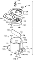
- FIG. 1 illustrates an exploded view of a modular floor box assembly 100 according to an embodiment of the present application.
- the modular floor box assembly 100 can include a floor box 102 having a housing 104 and a voltage divider 106, a power puck 108, and a cover assembly comprising a cover flange 110 and a cover lid 112, among other components.
- the power puck 108 can be a plug and play type device with respect to at least the transmission of electrical power, and can thus be configured to be indirectly electrically coupled to power transmission cables or wires (collectively referred to herein as cables) that are hardwired to the modular floor box assembly 100 at a lower, power layer 174 ( Figure 3 ) of the housing 104. Additionally, the power puck 108 can be configured to accommodate selective electrical coupling of the power puck 108 to a variety of different types of electrical devices in a variety of manners such that the power puck 108 can provide a means for electrical transmission to those other electrical devices.
- the power puck 108 can have a variety of shapes, sizes, and configurations so as to accommodate electrical transmission through a variety of types of receptacles 206, including but not limited to, different sized and/or shaped receptacles, as well as through a variety of different combinations of types of receptacles 206.
- the power puck 108 can be configured to provide receptacles 206 that correspond to a particular area(s) or jurisdiction(s) of use, including, for example, receptacles 206 that comply with domestic and/or foreign standards and/or receptacle configurations.
- the power puck 108 can be configured to accommodate selective electrical coupling of the power puck 108 to other power cables that may be positioned in, or pass through, an upper layer 172 ( Figure 3 ) of the housing 104.
- the power puck 108 can include one or more electrical receptacles 206 that can receive a mating adapter or plug 116 of a power cable 114 of a device, fixture, or other electrical receptacle that can be located outside of the housing 104.
- the power puck 108 can include one or more data receptacles 210 that can be communicatively coupled to one or more data cables positioned in the lower layer 174 of the housing 104, and which can also be selectively communicatively coupled to mating data transmission cables received in the upper layer 172 of the housing 104, and/or can be configured to accommodate such data transmission cables being pulled through the modular floor box assembly 100.
- Data transmission cables can include a variety of different types of cables and wires that can be used to transmit data or information, including, but not limited to, audio/visual cables, network cables, and media cables, such as, for example, HDMI cable, coaxial cable, optic fiber cable, and twisted pair cables, among other types cables or wires.
- FIGS 2-4 illustrate an exemplary housing 104 for a floor box 102 of the modular floor box assembly 100 according to an embodiment of the present application.
- the housing 104 can be constructed from a variety of different materials, including, for example, metallic and non-metallic materials, as well as a combination thereof.
- the housing 104 can be constructed from one or more of a stamped steel, cast iron, plastics, brass, black coated metal, and polyvinyl chloride (PVC), among other materials.
- the housing 104 includes a sidewall 118 and a bottom wall 120 that generally define an interior region 122 of the housing 104.
- the sidewall 118 can include opposing upper and lower portions 124, 126 of the sidewall 118, and can have a variety of shapes and configurations, including, for example, a generally cylindrical configuration, as shown in at least Figures 2-4 .
- the bottom wall 120 can be connected to the lower portion 126 of the sidewall 118, and can at least partially extend between opposing portions of the sidewall 118. As shown in at least Figure 3 , according to certain embodiments, the bottom wall 120 can include an orifice 128. Further, the upper portion 124 of the sidewall 118 may generally define an opening 130 of the interior region 122.
- the voltage divider 106 can be constructed to provide a barrier between cables within the lower, power layer 174 of the interior region 122 that are used in the transmission of electrical power from cables within the lower, power layer 174 of the interior region 122 that are used in connection with the transmission of data.
- the voltage divider 106 can be positioned such that, in the event cables associated with the transmission of data are to be pulled through the housing 104, including, for example, pulled through the opening 130 at the upper portion of the interior region 122, the voltage divider 106 can provide both a degree of protection for the data transmission cables and associated devices that are communicatively coupled to the data transmission cables from line voltage, and assist in preventing or minimizing such pulling of the data transmission cables from adversely impacting the power transmission cables and/or the associated hardwired electrical connections of those power transmission cables within the housing 104.
- the voltage divider 106 can be constructed or molded from a plurality of different types of metallic and non-metallic materials, including, but not limited to, metal, rubber, plastic, PVC, or ceramic, among other materials. Further, according to certain embodiments, the voltage divider 106 can be an integral piece, or, alternatively, molded to the housing 104 within the interior region 122 of the housing 104 so that the voltage divider 106 may not be removable from the housing 104.
- the sidewall 118 can include a pair of opposing slots 132 that can accommodate slideable displacement of a portion, of the voltage divider 106, as well as provide support for the inserted voltage divider 106 so as to at least assist in maintaining the voltage divider 106 at a selected position within the housing 104.
- the slots 132 can extend from the upper portion 124 to the lower portion 126 of the sidewall 118 such that the voltage divider 106 can be at least adjacent to, and may abut, the bottom wall 120 of the housing 104.
- Opposing edges 134 of the voltage divider 106 can each be inserted into a slot 132 so that the voltage divider 106 can be displaced along the slots 132 within the interior region 122 of the housing 104.
- one or both of the opposing edges 134 of the voltage divider 106 and/or the associated mating slots 132 of the housing 104 can be configured to at least assist in retaining an inserted voltage divider 106 within the slots 132.
- the opposing edges 134 of the voltage divider 106 can include protrusions, serrations, and/or teeth that can engage an adjacent surface of, or that define, the corresponding slot 132 in manner that can provide a resistance or gripping feature that opposes removal of the inserted voltage divider 106 from the slots 132.
- the inserted voltage divider can be retained in other manners with in the slots 132, such as, for example, via a mechanical fastener, such as, for example, a screw, bolt, or pin, and/or via use of an adhesive.
- the voltage divider 106 may not be removable from the housing 104 without a power deck 136 ( Figure 3 ) and the power puck 108 being removed from the interior region 122 of the housing 104.
- the housing 104 can also include a first set of fittings or ports 138a, 138b, and a second set of fittings or ports 140a, 140b that extend from, or adjoined to a portion of the lower portion 126 of the sidewall 118.
- Each fitting 138a, 138b, 140a, 140b can include a fitting wall 142 that generally defines a passageway 144 for the associated fitting 138a, 138b, 140a, 140b that extends through the fitting wall 142 and to the interior region 122 of the housing 104.
- the passageway 144 of each fitting 138a, 138b, 140a, 140b can provide a pathway for the ingress/egress of cables into/from/through the housing 104.
- each passageway 144 has a first opening 146 and an opposing second opening 148, the second opening 148 being adjacent to the interior region 122 of the housing 104 and positioned such that the bottom wall 120 of the housing 104 does not inhibit the ingress/egress of cables into/from the interior region 122 through the passageway 144.
- the first and second openings 146, 148 may, or may not, have the same size, such as, for example, diameters.
- At least the first opening 146 can have a size, such as, for example, diameter, that can accommodate insertion of a portion of a conduit into at least a portion of the passageway 144, such as, for example, pipe or tubing containing cables that are being delivered to, or passing from, the modular floor box assembly 100.
- the size of the first and/or second openings 146, 148 of the first set of fittings 138a, 138b such as, for example, diameter(s), may, or may not, be different than the corresponding size of the first and/or second openings 146, 148 of the second set of fittings 140a, 140b.
- the first and/or second openings 146, 148 for the first set of fittings 138a, 138b, and the associated fitting wall 142 may be smaller than the corresponding first and/or second openings 146, 148 for the second set of fittings 140a, 140b, and/or the associated fitting wall 142 for the second set of fittings 140a, 140b.
- one or more cables used in the transmission of electrical power can enter the passageway 144 through the first opening 146 of the first fitting 138a, and be delivered via the passageway 144 and through the second opening 148 of the first fitting 138a into the interior region 122 of the housing 104. Additionally, at least some of those same power transmission cables, and/or other power transmission cables, can exit the interior region 122 and/or housing 104 by entering the passageway 144 of the second fitting 138b through the second opening 148 and exit the housing 104 through the first opening 146 of the second fitting 138b.
- one or more cables used in the transmission of data can enter the passageway 144 of the corresponding first fitting 140a through the first opening 146, and be delivered via the passageway 144 and through the second opening 148 of the first fitting 140a into the interior region 122 of the housing 104. Further, at least some of those same data transmission cables, and/or other data transmission cables, can exit the interior region 122 and/or housing 104 by entering the second opening 148 of the second fitting 140b, and exit the housing 104 through the first opening 146 of the second fitting 140b.
- cables can also enter the housing 104 through the second fitting 138b, 140b, and exit from the housing 104 through the first fitting 138a, 140a.
- the first fitting 138a, 140a can be positioned at a variety of locations relative to the associated second fitting 138b, 140b and/or relative to a central longitudinal axis 150 ( Figure 3 ) of the housing 104.
- the first and second fittings 138a, 138b of the first set of fittings can generally be around 180 degrees apart from each other so as to be on opposing sides of the housing 104, as well as be at generally the same vertical height relative to a central longitudinal axis 150 of the housing 104.
- first and second fittings 138a, 138b of the first set of fittings can be generally aligned with each other along a first fitting axis 152 ( Figure 2 ) that is generally orthogonal to, and may or may not be offset from, the central longitudinal axis 150 of the housing 104.
- the first and second fittings 140a, 140b of the second set of fittings can be positioned and oriented relative to each other in a manner that is similar to the above-discussed relative positions and orientations of the first set of fittings, and, more specifically, the first and second fittings 138a, 138b of the first set of fittings.
- the first and second fittings 140a, 140b of the second set of fittings can be generally 180 degrees apart from each other and have similar heights such that the first and second fittings 140a, 140b of the second set of fittings are aligned with each other along a second fitting axis 154 that is generally parallel to the first fitting axis 152.
- the first and second fitting axes 152, 154 can be offset from the central longitudinal axis 150 such that the first and second fitting axes 152, 154 are on opposing sides of the central longitudinal axis 150.
- the first fittings 138a, 140a of the first and second set of fittings may be generally adjacent, or otherwise in relative close proximity to each other, and the second fittings 138b, 140b of the first and second set of fittings may be generally adjacent, or otherwise in relative close proximity to each other.
- At least some, if not all, of the fitting walls 142 can include indicia 156 that can assist with identification of whether a particular fitting 138a, 138b, 140a, 140b is intended for use with cables for particular types of transmissions, such as, for example, power transmission or data transmission.
- indicia 156 can provide an indication of the particular area within the interior region 122 that that is to receive electrical transmission cables, and the area(s) in the interior region 122 that is to receive the data transmission cables.
- some indicia 156 includes the word "POWER” in association with the first and second fittings 138a, 138b of the first set of fittings, and other indicia 156 includes the word "DATA" in association with the first and second fittings 140a, 140b of the second set of fittings.
- word "POWER” in association with the first and second fittings 138a, 138b of the first set of fittings
- DATA in association with the first and second fittings 140a, 140b of the second set of fittings.
- a variety of other words, letters, phrases, and/or symbols may be utilized for the indicia 156.
- the housing 104 can also include a plurality of anchors or feet 158 that can extend generally outwardly from the lower portion 126 of the sidewall 118 of the housing 104. As shown, according to the illustrated embodiment, the anchors 158 can outwardly extend in different directions. Additionally, the anchors 158 can include a through-hole or orifice 160 that is configured to accommodate passage of a mechanical fastener, such as, for example, a bolt, screw, or pin, among other fasteners, through the anchor 158.
- a mechanical fastener such as, for example, a bolt, screw, or pin
- the housing 104 can also include a power deck 136 that is positioned within the interior region 122 of housing 104.
- the power deck 136 can include a deck housing 162 and a power terminal block 164.
- the deck housing 162' can include an aperture 159 sized to receive the power terminal block 164, including, for example, a female receptor of the power terminal block 164.
- the deck housing 162 can be constructed from the same material as the sidewall 118.
- the sidewall 118, bottom wall 120, fitting walls 142, and deck housing 162 can form, or be part of, a monolithic structure.
- the power deck 136 can be selectively removable from, or displaceable within, the housing 104.
- the power deck 136 includes one or more tabs that are matingly received in the slots 132 of the housing 104 that can guide, as well as at least partially secure, a placement or position of the power deck 136 in the housing 104.
- the power deck 136 can include tabs that are received in the slots 132, and which can accommodate pivot displacement of the power deck so as to accommodate access to the power deck 136 and/or the lower, power layer 176 beneath the deck housing 162.
- one or more supports may inwardly protrude from the sidewall 118 of the housing 104 beneath the deck housing 162 that can provide support to the deck housing 162 and/or onto which the deck housing 162 can sit.
- the power deck 162 can, for example, be removed from the interior region 122 of the housing 104, or otherwise displaced relative to at least the housing 104, while power transmission cables are hardwired to the power terminal block 164.
- the power deck 136 which may, or may not, be removable, can also be further secured within the interior region 122 by a mechanical fastener, such as, for example, a screw, bolt, or pin, that can secure the position of the power deck 136 within the housing 104.
- a mechanical fastener such as, for example, a screw, bolt, or pin
- the power deck 136' and voltage divider 106' can form an integral, monolithic structure, as seen, for example, by the power deck 136' shown in Figure 16 .
- the deck housing 136' and voltage divider 106' may, or may not, have configurations similar to, or the same as. the deck housing 136 and voltage divider 106, respectively, that are discussed herein with respect to other embodiments.
- the opposing edges 134 of the voltage divider 106' can be inserted into mating slots 132 of the housing 104, as previously discussed.
- the voltage divider 106' can be retained within the slots 132, such as, for example, via engagement of protrusions, serrations, and/or teeth along the opposing edges 134 of the voltage divider 106' with an adjacent surface(s) of the slots 132, use of a mechanical fastener(s), and/or via an adhesive.
- one or more supports may inwardly protrude from the sidewall 118 of the housing 104 beneath the deck housing 162' shown in Figure 16 that can provide support to the deck housing 162' and/or onto which the deck housing 162' can sit.
- the vertical location of the power deck 136 within the housing 104, and moreover, along the central longitudinal axis 150 of the housing 104, can be based on a variety of criteria, including, for example, whether the associated power puck 108, when assembled to the modular floor box assembly 100, is to be downwardly recessed from, or flush with, the upper portion 124 of the sidewall 118 of the housing 104.
- the deck housing 162 can inwardly extend from an inner surface 166 of the sidewall 118 to an outer edge 168 of the deck housing 162. At least a portion of the outer edge 168 can be separated from an opposing portion of the inner surface 166 of the sidewall 118 by an aperture 170 such that the outer edge 168, and thus a portion of the deck housing 162, is detached from the sidewall 118.
- the deck housing 162 has a half circle shape in which the outer edge 168 of the deck housing 162 is generally parallel to the first and second fitting axes 152, 154, and generally orthogonal to the central longitudinal axis 150 of the housing 104.
- the outer edge 168 of the deck housing 162 may, or may not, intersect the central longitudinal axis 150 of the housing 104. Further, according to an illustrated embodiment, the outer edge 168 of the deck housing 162 can be positioned such that the aperture 170 is at least above a portion of the second fitting axis 154.
- the aperture 170 can provide an area in which data transmission cables from the first and/or second fittings 140a, 140b of the second set of fittings can be positioned to be operably coupled to at least a portion of the power puck 108, and/or a location that can accommodate data transmission cables being pulled through the modular floor box assembly 100, such as data transmission cables that extend from at least the first and/or second fittings 140a, 140b and the opening 130 of the interior region 122 of the housing 104.
- power deck 136' can include the deck housing 162' and a rim portion 163.
- the rim portion 163 can extend from opposing ends of an outer edge 168' of the deck housing 162' and generally have an arc shape.
- the rim portion 163 and an outer periphery 157 of the deck housing 162' can be shaped to generally conform to the shape of the portions of the inner surface inner surface 166 of the sidewall 118 of the housing 104 that will be adjacent to the deck housing 162' and the rim portion 163 when the power deck 136' is installed in the housing 104.
- the power deck 136' can have a generally a circular outer shape.
- the aperture 170 can be positioned between, or generally defined by, the outer edge 168' of the deck housing 162' and the rim portion 163. Additionally, according to certain embodiments, an upper surface 161 of the rim portion 163 may, or may not, be generally coplanar to a corresponding upper surface 176 of the deck housing 162'.
- the deck housing 162' and thus at least a portion of the power deck 136', can be supported in the housing 104 in a manner similar to that discussed above with respect to the deck housing 162 shown in at least Figures 4 and 5 .
- the voltage divider 106' can also provide support for the power deck 136'.
- the power deck 136' can include one or more support arms 165 that extend generally in a down direction from the rim portion 163 to the bottom wall 120 of the housing 104 that can also provide support for the power deck 136'.
- the support arm 165 can downwardly extend from the rim portion 163 in a direction that is generally parallel to the direction that the voltage divider 106' downwardly extends from the deck housing 162' and/or the rim portion 163.
- the support arm 165 is positioned such that, when the power deck 136' is installed in the housing 104, the support arm 165 is generally adjacent to, if not abuts, the inner surface 166 of the sidewall 118 of the housing 104.
- the support arm 165 can have a shape that generally conforms to the shape of the adjacent portion of the inner surface 166 of the sidewall 118 of the housing 104, such, as, for example, a curved cross-sectional shape.
- the support arm 165 can be positioned to minimize, if not prevent, the support arm 165 from interfering with the ingress/egress of cables through the aperture 170.
- the deck housing 162 can be generally parallel to the bottom wall 120 of the housing 104, and perpendicular to the central longitudinal axis 150 of the housing 104. Further, the deck housing 162 can provide a divider for the upper layer 172 and the lower layer 174 of the interior region 122 of the housing 104. As previously discussed, the lower layer 174, which can also be referred to as a power layer, can be configured to house the cable(s) that is/are received into the interior region 122 from any of the first and second sets of fittings 138a, 138b, 140a, 140b.
- the voltage divider 106 can be positioned to generally extend between, or from, the deck housing 162 and the bottom wall 120 of the housing 104, as well as be positioned to at least separate the power transmission cables in the interior region 122 that are passing through the first and/or second fittings 138a, 138b of the first set of fittings, from the data transmission cables in the interior region 122 that are passing through the first and/or second fittings 140a, 140b of the second set of fittings.
- the deck housing 162 can include an upper surface 176 and a lower surface 178.
- the power terminal block 164 can be coupled to the lower surface 178 of the deck housing 162 in a variety of manners.
- the power terminal block 164 and the deck housing 162 can be part of a unitary, monolithic structure.
- the power terminal block 164 can be secured to the lower surface 178 of the deck housing 162 by one or more mechanical connections, mechanical fasteners, rivets, spot welding, brazing, soldering, and/or an adhesive, among other manners of attachment.
- the power terminal block 164 can include a plurality of terminals 180 that can each be connected to a power transmission cable.
- the power terminal block 164 can include one or more terminals 180, including, for example, screw terminals and/or quick connect terminals, for hardwiring the power terminal block 164 to each of a load line(s), neutral line(s), and ground. Such hardwired connections can, in at least some situations, be performed by an electrician or other electrically trained technician, among other individuals.
- the power terminal block 164 can be electrically coupled to one or more status indicators 182, which can provide a visual indication of the status of one or more electrical connections of the power terminal block 164.
- the status indicator 182 can provide a separate visual indication of the status of an electrical connection, if any, of the power terminal block 164 to each of a load line, a neutral line, and ground, and/or an indication as to whether electrical power is being received by the power terminal block 164.
- the status indicator 182 is an array of lights that comprises a first light 182a that provides a status indication with respect to a connection and/or electrical transmission along the load line(s), a second light 182b that provides a status indication with respect to a connection and/or electrical transmission along the neutral line(s), and a third light 182c that provides an indication as to whether the power terminal block 164 is connected to ground.
- the status indicators 182 can be positioned at a variety of locations along the deck housing 162, including, for example, positioned in one or more openings 190 in the deck housing 162. Further, the status indicators 182 are positioned to accommodate visual detection when being viewed at least from a position above the top portion of the sidewall 118 of the housing 104, and/or when observing the upper surface 176 of the deck housing 162.
- the deck housing 162 can further include a deck receptor 184 that is electrically coupled to the power terminal block 164.
- the deck receptor 184 is further configured for selective electrical coupling to the power puck 108 such that electrical power can be delivered from the power terminal block 164 to the power puck 108 via the power puck 108 being electrically coupled to the deck receptor 184.
- the deck receptor 184 can be a female electrical receptor or socket that is safe to the touch, otherwise referred to as touch safe.
- the deck receptor 184 comprises a female receptor or socket having a plurality of openings 186 that extend through the upper surface 176 of the deck housing 162.
- the plurality of openings 186 can accommodate a plug-in connection in which the mating pins 189 of a male receptacle 188 ( Figure 8 ) of the power puck 108 passes through, or plug into, the deck housing 162 so as to become electrically coupled to the corresponding electrical contacts of the power terminal block 164.
- electrical contact between the electrical conductors of the deck receptor 184 and mating pins 189 of the male receptacle 188 of the power puck 108 occurs below at least the upper surface 176 of the deck housing 162, and/or beneath the deck housing 162, such that the deck housing 162 and the limited size of the openings 186 of the deck receptor 184 can shield a user from at least incidental, and potentially dangerous, direct contact with the electricity, and thus can protect the user from possible electrocution.
- the deck receptor 184 can accommodate relatively safe and simple operable installation or assembly of the power puck 108 to the floor box 102 by a novice user of the modular floor box assembly 100, including the novice user being able to electrically couple the power puck 108 to the electrical power delivered to the hardwired power terminal block 164 without necessitating disconnect or interrupting the supply of power that is being delivered to the power terminal block 164.
- such a configuration can also accommodate, if needed, relatively safe and simple removal of the power puck 108 from the floor box 102, including a hot-swap in which a power puck 108 is removed from the modular floor box assembly 100 while electrical power is still being delivered to the power terminal block 164, as well as subsequent re-installation or replacement of the power puck 108 in the floor box 102, again without interruption in the delivery of electrical power to the to the hardwired power terminal block 164.
- a variety of different types of touch safe plug-in connection configurations can be utilized for the female deck receptor 184 of the power puck 108 and the mating male receptacle 188 of the power puck 108.
- the female deck receptor 184 and mating male receptacle 188 can utilize a blade and fork connection configuration, pin and sleeve connection configuration, a twisting lock detail, or a cable having a male receptacle in the form of a plug that can be electrically coupled to the female deck receptor 184 in only one way or manner.
- power can be transmitted across the power deck 136 to the power puck 108 via induction power transmission, or via use of conductive polymers.
- a portion of the inner surface 166 of the sidewall 118 of the housing 104 that is not directly connected to the deck housing 162 can include a ledge or rim 192 that can, along with the deck housing 162, provide support for the power puck 108.
- the rim 192 can inwardly extend from a portion of the sidewall 118 that is positioned on a side of the aperture 170 that opposes the deck housing 162.
- the rim 192 and deck housing 162 can generally be positioned on opposing, or different, sides of the aperture 170.
- An upper surface 194 of the rim 192 can be generally co-planar with the upper surface 176 of the deck housing 162 such that the power puck 108 can be supported in a generally level position by the deck housing 162 and the rim 192. Further, according to certain embodiments, the upper surfaces 176, 194 of the deck housing 162 and rim 192 can be generally parallel to the bottom wall 120 of the housing 104 and/or generally perpendicular to the central longitudinal axis of the housing 104.
- the power puck 108 includes an outer wall 196 that extends between opposing top and bottom walls 198, 200 of the power puck 108.
- the distance that the outer wall 196 extends between the top and bottom walls 198, 200 can be based on a variety of criteria, including, for example, whether the power puck 108 is to be positioned at a recessed position in the interior region 122 of the housing 104 relative to at least a portion of the upper portion 124 of the sidewall 118, or if the power puck 108 is to be generally flush with the upper portion 124 of the sidewall 118.
- the outer, top, and bottom walls 196, 198, 200 of the power puck 108 can be constructed from a variety of different materials, including, for example, generally electrically non-conductive or insulative materials, such as, but not limited to, rubber, plastic, PVC, ceramics, and/or a combination thereof, among other materials. Further, the outer, top, and/or bottom walls 196, 198, 200 can generally define at least portions of one or more interior region(s) 202a, 202b, 202c of the power puck 108 that may, or may not, be at least partially hollow.
- the outer wall 196 of the power puck 108 can have a variety of shapes and sizes. According to the illustrated embodiment, the outer wall 196 has a shape and size that can accommodate the power puck 108 being positioned in the upper layer 172 of the interior region 122 of the housing 104 at least at a position at which at least a portion of the bottom wall 200 of the power puck 108 is positioned against the upper surfaces 176, 194 of the deck housing 162 and the rim 192. According to certain embodiments, the outer wall 196 has, for example, a generally cylindrical configuration with a cross sectional diameter that is generally similar, if not smaller, than a corresponding diameter for the inner surface 166 of the sidewall 118 of the housing 104.
- the top wall 198 of the power puck 108 can include one or more socket openings 204 configured for placement of one or more corresponding electrical receptacles 206.
- the one or more socket openings 204 can be positioned such that, when the power puck 108 is assembled to the floor box 102, and thus the power puck 108 is electrically coupled to the power terminal block 164, at least a portion of the socket openings 204 overlap at least a portion of the below deck housing 162 and the portion of the lower layer 174 of the interior region 122 that contains the power transmission cables.
- the one or more socket openings 204 can be sized to house a single electrical receptacle 206 or a plurality of electrical receptacles 206.
- the more socket openings 204 can be configured for a variety of different types of electrical connections with a mating the power plug 116 of a power cable 114 of an external device, including, but not limited to, accommodated a mating connection involving a blade and fork connection, pin and sleeve connection, a twisting lock detail, or a connection with a cable having a male receptacle in the form of a plug that can be connected to a mating female electrical receptacle 206 in only one way or manner.
- the one or more socket openings 204 can be in fluid communication with a first interior region 202a of the power puck 108 that can house at least a portion of the electrical receptacles 206.
- the first interior region 202a can also be positioned to accommodate connectors or cables that electrically couple the electrical receptacles 206 to the male receptacle 188 of the power puck 108 such that, when the power puck 108 is assembled in the floor box 102, electrical power can be delivered from the power terminal block 164 to the electrical receptacles 206.
- the power puck 108 may only include one or more electrical receptacles 206, according to other embodiments, the top wall 198 of the power puck 108 can also include one or more data openings 208 configured for placement of, or accommodate access to, one or more corresponding data receptacles 210 of the power puck 108.
- the one or more data openings 208 can be positioned such that, when the power puck 108 is assembled to the floor box 102, and thus the power puck 108 is electrically coupled to the power terminal block 164, at least a portion of the data openings 208 overlap at least a portion of the aperture 170 between the deck housing 162 and the rim 192, as well as overlap at least a portion of the lower layer 174 of the housing 104 that contains the data transmission cables.
- at least a portion of the data receptacles 210 can be positioned within a second interior region 202b of the power puck 108 that is in fluid communication with the one or more data openings 208.
- the bottom wall 200 of the power puck 108 can include an access port 212 that can be in fluid communication with the second interior region 202b and/or the data openings 208.
- the access port 212 can provide a passageway for data transmission cables that enter and/or pass from the floor box 102 via the second set of fittings 140a, 140b to be coupled to the data receptacles 210.
- a removable cover 214 can be secured to the bottom wall 200 to prevent the ingress/egress of cables or materials through the access port 212.
- the cover 214 can be selectively, and removably, secured to the power puck 108 via one or more mechanical fasteners 216, such as, for example, screws, that may threadingly securely engage the power puck 108.
- the one or more data openings 208 can be configured to accommodate one or more types of data receptacles 184.
- the data receptacles 210 can be configured to be communicatively coupled to data transmission cables that may enter into the interior region 122 of the housing 104 via one or both of the first and second fittings 140a, 140b of the second set of fittings, and which may be pulled into the data openings 208 through the aperture 170.
- the data receptacles 210 can be configured for a variety of different types of connections to data transmission cables, and moreover, to the adapters or connectors of such data transmission cables, including traditional or proprietary adapter connections, as well as combinations thereof.
- data receptacles 210 can be configured to be coupled to data transmission cables associated with a variety of different types of devices, including, for example, devices that can utilize two-wire bus, fiber optic, wireless, universal serial bus, or analog communication; devices that utilize all digital language forms for any and all digital communication devices; devices that utilize analog signals; HVAC controls; temperature and measurement controls; water detection and drivers to shut off water supply; protection and control circuits; room automation; occupant detection; and, security monitoring communication, including at least video and audio, as well as infrared passive and active monitoring; and UHF or sonic detection devices.
- devices that can utilize two-wire bus, fiber optic, wireless, universal serial bus, or analog communication devices that utilize all digital language forms for any and all digital communication devices; devices that utilize analog signals; HVAC controls; temperature and measurement controls; water detection and drivers to shut off water supply; protection and control circuits; room automation; occupant detection; and, security monitoring communication, including at least video and audio, as well as infrared passive and active monitoring; and UHF or sonic detection devices.
- the power puck 108 can also include a viewing window 218 that passes through the power puck 108, including through the top and bottom walls 198, 200 of the power puck 108 so as to accommodate visual access to the status indicators 182a, 182b, 182c (collectively status indicator 182) of the power deck 136.
- the viewing window 218 can extend between, and through, both the top wall 198 and bottom wall 200, respectively, of the power puck 108, and thus provide a third interior region 202c in the power puck 108.
- the viewing window 218 is positioned such that, at least when the male receptacle 188 of the power puck 108 is electrically coupled to the deck receptor 184, the viewing window 218 is positioned at least over at least a portion of the status indicators 182 and/or positioned to provide visual access to a visual representation of the status indicators 182.
- the viewing window 218 can include a transparent or semi-transparent cover that can accommodate visual access to the status indicators 182, while also providing a shield against debris entering, via the viewing window 218, into, or through, the power puck 108.
- power pucks 108, 108', 108" can have a variety of configurations with respect to at least the number of socket openings 204 and/or data openings 208, as well as the number of associated electrical receptacles 206 and/or data receptacles 210.
- Figures 7 and 11 illustrate embodiments of power pucks 108, 108" having four socket openings 204 and four associated electrical receptacles 206
- Figure 10 illustrates another embodiment in which the power puck 108' includes two socket openings 204 and two associated electrical receptacles 206.
- Figure 7 illustrates a power puck 108 having a single data opening 208 that houses a data receptacle 210 having six data connectors 218, the power puck 108 shown in Figure 10 has two data openings 208, each of which includes a data receptacle 210 having six data connectors 218, thereby providing twelve data connectors 218.
- Figure 11 illustrates an embodiment in which, rather than having a data receptacle 210, the power puck 108 is configured for data transmission cables to be pulled through the data opening 208 and associated second interior region 202b. According to such a configuration, the data opening 208 and associated second interior region 202b can include corner protection for the protection of the sheathing on the data transmission cables.
- the power pucks 108, 108', 108" can include one or more electrical receptacles 206 that are configured to receive a type of connector, that is different than, or has a different configuration, than the type or configuration of connector that another electrical receptacle 206 of the power puck 108, 108', 108" is configured to receive.
- the power puck 108, 108', 108" can also include a mixture of different types, or configurations, of data receptacles 210.
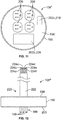
- Figure 12 illustrates another exemplary power puck 108'" according to an embodiment of the subject application.
- the power puck 108"' can have a power whip 220 comprising a cable having an outer sheath 222 that houses a plurality of wires 224a-f that can be used in connection with delivering at least electrical power received by the power puck 108"' from the power deck 136.
- a power whip 220 can be used in numerous applications, including, but not limited to, in connection with the delivery of electrical power for use with office cubicles and furniture.
- the power whip 220 in addition to providing wires used in the transmission of electrical power, can also include one or more data transmission cables that can include, or are in operable communication with, cable transmission cables that pass through one or more of the first and second fittings 140a, 140b of the second set of fittings.
- the power puck 108 can further include one or more engagement bodies 198 that can improve the ease with which the power puck 108 can be positioned within, and/or removed from, the housing 104.
- the engagement body 198 upwardly project from the top wall 198 of the power puck 108 so as to provide an area that can be grasped by a user and/or a tool.
- the engagement body 1998 can comprise one or more handles, at least a portion of which is upwardly projected, or offset, from the top wall 198 of the power puck 108 so that the engagement body 198 is accessible to a user or installer at least when the power puck 108 is, or is being brought into, electrical contact with the power terminal block 164.
- the engagement body 198 may comprise a pair of legs 195 that are adjoined together by a cross bar 197 that is positioned above the top wall 198 of the power puck 108.
- such a configuration can generally define an opening 199 between the legs 195, crossbar 197, and top wall 198 that can accommodate placement of at least a portion of a digit of an installer.
- the engagement body 198 may be retractable such that at least a portion of the engagement body 198 can, when not being used, be positioned beneath the top wall 198 of the power puck 108.
- the engagement body 198 can be pivotally connected to the power puck 108 so as to, when not in use, minimize potential interference by the engagement body 198 with at least plugs or connectors that can be electrically coupled to the power puck 108.
- the one or more engagement bodies 198 can comprise one or more recesses or cavities that may extend through, and beneath, at least a portion of the top wall 198 of the power puck 108.
- Such recesses or cavities can be sized to accommodate placement of at least a portion of a digit of a user beneath the top wall 198 of the power puck 108, and thereby provide a location for a user to engage the power puck 108 when installing the power puck 108 into the housing 104, as well as a location where the user can provide a pulling force beneath, or to a backside of, the top wall 198 so as to be able to pull the power puck 108 away from the housing 104.
- the modular floor box assembly 100 can also include a cover flange 110 that can be secured about the upper portion 124 of the sidewall 118 of the housing 104.
- the cover flange 110 can include a recess or groove in a flange 226 of the cover flange 110 that can relatively securely receive placement of, or be positioned around, at least a portion of the upper portion 124 of the sidewall 118 of the housing 104.
- the flange 226 can include an opening 228 that is positioned to be in fluid communication with the interior region 122 such that cables can pass through the opening 228 of the flange 226 and into, or out of, the interior region 122 of the housing 104.
- the flange 226 can have a size, such as, for example, a diameter, that is larger than a corresponding size of the sidewall 118 of the housing 104, such that the flange 226 extends over an interface or space between the sidewall 118 and the adjacent portion of the floor 230 into which the floor box 102 is installed, as shown in Figure 15 .
- the cover flange 110 can include a selectively displaceable cover lid 112.
- the cover lid 112 can be pivotally coupled or tethered to the cover flange 110 by a one or more arms or cables 232 or a hinge such that the cover lid 112 can be displaced from a closed position at which the cover lid 112 covers the opening 130 of the interior region 122 of the housing 104 so as to prevent ingress/egress into/from the interior region 122, to an open position ( Figures 13 and 14 ) at which at least a portion of the cover lid 112 has been moved to a position away from the opening 130 of the interior region 122.
- the cover flange 110 can be pivotally coupled to the housing 104, such as, for example, via a hinge, such that the cover flange 110 and the cover lid 112 can be pivoted away from the interior region 122.
- the cover lid 112 and/or cover flange 110 can include a gasket that can be configured to at least prevent or minimize the ingress of debris or fluid into the interior region 122 of the housing 104.
- the cover flange 110 can include a latch system that can assist in retaining the cover lid 112 in a closed position.
- the latch system can include one or more tabs 236 on the cover lid 112 and a slideable retainer 238 on the cover flange 110.
- the slideable retainer 238 When in the cover flange 110 is in the closed position, the slideable retainer 238 can be in a first position at which the retainer 238 extends over the one or more tabs 236 of the cover lid 112 so as to provide interference against the cover lid 112 being displaced to the open position.
- the retainer 238 When the cover lid 112 is to be opened, the retainer 238 can be slid in a generally outwardly direction to a second position away from the tabs 238 so that the retainer 238 no longer extends over the tabs 236, and thus the retainer 238 no longer interferes with the cover lid 112 being displaced to the open position.
- a biasing member such as, for example, a spring, may bias the retainer 238 toward the first position.
- the latch system can have a variety of other configurations and components to assist in selectively retaining the cover lid 112 in the closed position, including, but not limited to, embodiments in which the cover lid 112 can be rotated between locked and unlocked positions, and in which the cover lid 112 may be removed from the cover lid 112 when in the unlocked position, or alternatively, be lifted to an open position while remaining connected or tethered to the cover flange 110.
- the power puck 108 and the cover flange 110 can be integrated into a single, unitary component.
- assembly of the power puck 108 to the floor box 102 such as, for example, plugging the male receptacle 188 of the power puck 108 into the power deck 136, can coincide with the cover flange 110, and associated cover lid 112, being assembled to the housing 104.
- Such an embodiment can also include a self-leveling mechanism that can ensure that at least the cover flange 110 is relatively level with the surrounding floor surface when the power puck 108 is electrically coupled to the power deck 136.
- the power puck 108 can be pivotally coupled to the cover flange 110 such that, if needed, the power puck 108 can be angularly offset, including non-parallel, relative to the flange 226 of the cover flange 110.
- the modular floor box assembly 100 can also include one or more lighting devices 234 having a light bulb or source within the interior region 122 of the housing 104.
- the lighting device 234 can be powered via an electrical connection between the lighting device 234 and the power terminal block 164.
- Such a lighting device 234 can illuminate at least a portion of the interior region 122 of the housing 104 at least while a user is making electrical and/or data connections in, or with, the modular floor box assembly 100.
- the lighting device 234 can be positioned at a variety of locations within the housing 104, including, for example, above the power deck 136, on the power deck 136, or below the power deck 136.
- the lighting device 234 can be at a position at which the lighting device 234 provides a backlight within the housing 104.
- activation of the lighting device 234 can be controlled by a switch 240.
- the switch 240 can be automatically activated and deactivated, or, alternatively, manually operated.
- the light switch 240 can be positioned for engagement by, or release from engagement with, the cover lid 112 of the cover flange110 such that, upon displacement of the cover lid 112 to an open position, the switch 240 moves to a closed position, thereby resulting in illumination of the lighting device 234. Subsequent engagement with, or release from engagement with, the cover lid 112 as the cover lid 112 is returned to the closed position can facilitate the switch 240 moving to an open position, thereby ceasing illumination of the lighting device 234.
- the switch 240 can be configured for manual operation by a user such that the user can displace the switch 240 between open and closed positions by physically displacing at least a portion of the switch 240.
- Figure 15 illustrates an exemplary modular floor box assembly 100 installed in a floor 230.
- the modular floor box assembly 100 can be utilized with a variety of different types of floors, as well as installed at various times relative to the floor installation process.
- the modular floor box assembly 100 can be positioned prior to the pouring of the concrete for the floor 230, in which case the poured concrete can cure around the modular floor box assembly 100.
- the modular floor box assembly 100 can be a poke-thru device that is positioned in a hole that is drilled into a hardened concrete floor 230.
- concrete for the floor 230 can be poured around a cast or mold, and the modular floor box assembly 100 can later be placed in the void in the concrete floor 230 that is/was provided by the cast or mold.
- the modular floor box assembly 100 can also be used with other types of floors or structural elements that can be constructed from a variety of materials, including for example, but not limited to, wood floor joists, wood subfloor decking, accessed floor construction, and raised floor concepts, among other types of floors and structures.
Landscapes
- Engineering & Computer Science (AREA)
- Architecture (AREA)
- Civil Engineering (AREA)
- Structural Engineering (AREA)
- Connector Housings Or Holding Contact Members (AREA)
Abstract
Description
- The present invention relates to floor boxes, and more particularly, to modular floor box assemblies.
- The assembly of an electrical device to a floor box can often involve an electrician modifying the configuration of the floor box so that the floor box can accommodate the electrical device. Additionally, subsequent repairs or modifications to the electrical device, and/or to the associated supports of the electrical device, can sometimes necessitate the replacement of the floor box. Yet, as floor boxes can be secured in a variety of different types of floors, including, for example, concrete floors, such replacement can involve relatively significant demolition, and subsequent repairing, of the floor, which can be relatively costly, time consuming, and disruptive.
- Accordingly, although various types of floor boxes are currently available in the marketplace, further improvements are possible to provide a means for providing modular floor boxes.
- An aspect of an embodiment of the present application is a modular floor box assembly that includes a floor box having a housing, the housing including a plurality of fittings, each of the plurality of fittings having a passageway sized to receive a plurality of cables, the passageway being in fluid communication with an interior region of the housing. The modular floor box assembly can further include a power deck configured for placement within the interior region of the housing, the power deck including a female deck receptor that is electrically coupled to one or more terminals of the floor box that are configured for a hardwired connection within the interior region with at least one of the plurality of cables. Additionally, the housing can include an aperture within the interior region between the power deck and an opposing inner surface of the housing, the aperture being sized to accommodate passage of one or more data transmission cables, and is in fluid communication with the passageway of at least one of the plurality of fittings. Additionally, a power puck can be sized for removable placement within the interior region of the housing, the power puck having a male receptacle configured for insertion into, and electrical coupling to, the female deck receptor. The power puck can further include one or more electrical receptacles and at least one data opening, the one or more electrical receptacles being electrically coupled to the male receptacle.
- Another aspect of an embodiment of the present application is a modular floor box assembly that can include a floor box having a housing, a first fitting, and a second fitting, the housing having a sidewall and a bottom wall, the sidewall and the bottom wall defining an interior region of the housing, and each of the first fitting and the second fitting having a passageway that is in fluid communication with the interior region. The modular floor box assembly can also include a power deck having a deck housing that includes a female deck receptor, and a power terminal block having a plurality of terminals, each terminal of the plurality of terminals being configured for a hardwired connection with a power transmission cable received into the interior region through the first fitting. Further, the power terminal block can be electrically coupled to the female deck receptor. The modular floor box assembly can also include a power puck having a male receptacle sized and positioned to be plugged into the female deck receptor to electrically couple the male receptacle to the female deck receptor. The power puck can be selectively removable from the floor box, and can further include one or more electrical receptacles electrically coupled to the male receptacle and at least one data opening.
- Additionally, an aspect of an embodiment of the present application is a method that comprises hardwiring one or more power transmission cables to a power terminal block, the power terminal block being electrically coupled to a power deck of a floor box, and positioning one or more data transmission cables in an interior region of the floor box. Additionally, a power puck can be inserted into the interior region of the floor box, and, with the power deck in the interior region of the floor box, a male receptacle of the power puck can be plugged into a female deck receptor of the power deck, the female deck receptor being electrically coupled to the power terminal block. Further, an electrical receptacle of the power puck can be connected to a power cable for an external device, the electrical receptacle being electrically coupled to the male receptacle. The method can also include inserting the one or more data transmission cables through an aperture between the power deck and an interior surface of the floor box, and into a data opening in the power puck.
- These and other aspects of the present invention will be better understood in view of the drawings and following detailed description.
- The description herein makes reference to the accompanying figures wherein like reference numerals refer to like parts throughout the several views.
-
Figure 1 illustrates an exploded view of a modular floor box assembly according to an embodiment of the present application. -
Figure 2 illustrates a top side view of an exemplary housing for a floor box of a modular floor box assembly according to an embodiment of the present application. -
Figure 3 illustrates a cross sectional view of the housing taken along line A-A ofFigure 2 . -
Figure 4 illustrates a top side perspective view of the housing shown inFigure 2 . -
Figure 5 illustrates a top side perspective view of a cross section of the housing and a perspective view of a power puck in a dissembled position according to an embodiment of the present application. -
Figure 6 illustrates a bottom side perspective view of a cross section of the housing and a perspective view of a portion of the power puck shown inFigure 5 in an assembled position. -
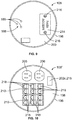
Figures 7, 8 , and9 illustrate top, side, and bottom views, respectively, of an exemplary power puck according to an embodiment of the present application. -
Figures 10 ,11, and 12 illustrate exemplary alternative configurations for power pucks according to embodiments of the present application. -
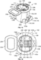
Figures 13 and 14 illustrate a side perspective view and a top view, respectively, of a modular floor box assembly according to an embodiment of the present application. -
Figure 15 illustrates a side view of the modular floor box assembly shown in at leastFigure 13 installed in a floor according to an embodiment of the present application. -
Figure 16 illustrates an exploded view of a floor box and a power deck having an integral divider wall for a modular floor box assembly according to an embodiment of the present application. -
Figure 17 illustrates a perspective view of a modular floor box assembly that includes a power puck having engagement bodies according to an embodiment of the present application. - The foregoing summary, as well as the following detailed description of certain embodiments of the present application, will be better understood when read in conjunction with the appended drawings. For the purpose of illustrating the application, there is shown in the drawings, certain embodiments. It should be understood, however, that the present application is not limited to the arrangements and instrumentalities shown in the attached drawings. Further, like numbers in the respective figures indicate like or comparable parts.
- Certain terminology is used in the foregoing description for convenience and is not intended to be limiting. Words such as "upper," "lower," "top," "bottom," "first," and "second" designate directions in the drawings to which reference is made. This terminology includes the words specifically noted above, derivatives thereof, and words of similar import. Additionally, the words "a" and "one" are defined as including one or more of the referenced item unless specifically noted. The phrase "at least one of' followed by a list of two or more items, such as "A, B or C," means any individual one of A, B or C, as well as any combination thereof.
-
Figure 1 illustrates an exploded view of a modularfloor box assembly 100 according to an embodiment of the present application. The modularfloor box assembly 100 can include afloor box 102 having ahousing 104 and avoltage divider 106, apower puck 108, and a cover assembly comprising acover flange 110 and acover lid 112, among other components. - As discussed below, the
power puck 108 can be a plug and play type device with respect to at least the transmission of electrical power, and can thus be configured to be indirectly electrically coupled to power transmission cables or wires (collectively referred to herein as cables) that are hardwired to the modularfloor box assembly 100 at a lower, power layer 174 (Figure 3 ) of thehousing 104. Additionally, thepower puck 108 can be configured to accommodate selective electrical coupling of thepower puck 108 to a variety of different types of electrical devices in a variety of manners such that thepower puck 108 can provide a means for electrical transmission to those other electrical devices. Accordingly, thepower puck 108 can have a variety of shapes, sizes, and configurations so as to accommodate electrical transmission through a variety of types ofreceptacles 206, including but not limited to, different sized and/or shaped receptacles, as well as through a variety of different combinations of types ofreceptacles 206. Similarly, thepower puck 108 can be configured to providereceptacles 206 that correspond to a particular area(s) or jurisdiction(s) of use, including, for example,receptacles 206 that comply with domestic and/or foreign standards and/or receptacle configurations. Accordingly, as discussed below, thepower puck 108 can be configured to accommodate selective electrical coupling of thepower puck 108 to other power cables that may be positioned in, or pass through, an upper layer 172 (Figure 3 ) of thehousing 104. For example, as shown inFigure 1 thepower puck 108 can include one or moreelectrical receptacles 206 that can receive a mating adapter orplug 116 of apower cable 114 of a device, fixture, or other electrical receptacle that can be located outside of thehousing 104. Additionally, as also discussed below, thepower puck 108 can include one ormore data receptacles 210 that can be communicatively coupled to one or more data cables positioned in thelower layer 174 of thehousing 104, and which can also be selectively communicatively coupled to mating data transmission cables received in theupper layer 172 of thehousing 104, and/or can be configured to accommodate such data transmission cables being pulled through the modularfloor box assembly 100. Data transmission cables can include a variety of different types of cables and wires that can be used to transmit data or information, including, but not limited to, audio/visual cables, network cables, and media cables, such as, for example, HDMI cable, coaxial cable, optic fiber cable, and twisted pair cables, among other types cables or wires. -
Figures 2-4 illustrate anexemplary housing 104 for afloor box 102 of the modularfloor box assembly 100 according to an embodiment of the present application. Thehousing 104 can be constructed from a variety of different materials, including, for example, metallic and non-metallic materials, as well as a combination thereof. For example, according to certain embodiments, thehousing 104 can be constructed from one or more of a stamped steel, cast iron, plastics, brass, black coated metal, and polyvinyl chloride (PVC), among other materials. Thehousing 104 includes asidewall 118 and abottom wall 120 that generally define aninterior region 122 of thehousing 104. Thesidewall 118 can include opposing upper andlower portions sidewall 118, and can have a variety of shapes and configurations, including, for example, a generally cylindrical configuration, as shown in at leastFigures 2-4 . Thebottom wall 120 can be connected to thelower portion 126 of thesidewall 118, and can at least partially extend between opposing portions of thesidewall 118. As shown in at leastFigure 3 , according to certain embodiments, thebottom wall 120 can include anorifice 128. Further, theupper portion 124 of thesidewall 118 may generally define an opening 130 of theinterior region 122. - The
voltage divider 106 can be constructed to provide a barrier between cables within the lower,power layer 174 of theinterior region 122 that are used in the transmission of electrical power from cables within the lower,power layer 174 of theinterior region 122 that are used in connection with the transmission of data. Further, thevoltage divider 106 can be positioned such that, in the event cables associated with the transmission of data are to be pulled through thehousing 104, including, for example, pulled through theopening 130 at the upper portion of theinterior region 122, thevoltage divider 106 can provide both a degree of protection for the data transmission cables and associated devices that are communicatively coupled to the data transmission cables from line voltage, and assist in preventing or minimizing such pulling of the data transmission cables from adversely impacting the power transmission cables and/or the associated hardwired electrical connections of those power transmission cables within thehousing 104. - According to the illustrated embodiment, the
voltage divider 106 can be constructed or molded from a plurality of different types of metallic and non-metallic materials, including, but not limited to, metal, rubber, plastic, PVC, or ceramic, among other materials. Further, according to certain embodiments, thevoltage divider 106 can be an integral piece, or, alternatively, molded to thehousing 104 within theinterior region 122 of thehousing 104 so that thevoltage divider 106 may not be removable from thehousing 104. Alternatively, thesidewall 118 can include a pair of opposingslots 132 that can accommodate slideable displacement of a portion, of thevoltage divider 106, as well as provide support for the insertedvoltage divider 106 so as to at least assist in maintaining thevoltage divider 106 at a selected position within thehousing 104. Theslots 132 can extend from theupper portion 124 to thelower portion 126 of thesidewall 118 such that thevoltage divider 106 can be at least adjacent to, and may abut, thebottom wall 120 of thehousing 104. Opposingedges 134 of thevoltage divider 106 can each be inserted into aslot 132 so that thevoltage divider 106 can be displaced along theslots 132 within theinterior region 122 of thehousing 104. According to at least certain embodiments, one or both of the opposingedges 134 of thevoltage divider 106 and/or the associatedmating slots 132 of thehousing 104 can be configured to at least assist in retaining an insertedvoltage divider 106 within theslots 132. For example, according to certain embodiments, the opposingedges 134 of thevoltage divider 106 can include protrusions, serrations, and/or teeth that can engage an adjacent surface of, or that define, thecorresponding slot 132 in manner that can provide a resistance or gripping feature that opposes removal of the insertedvoltage divider 106 from theslots 132. Alternatively, or additionally, the inserted voltage divider can be retained in other manners with in theslots 132, such as, for example, via a mechanical fastener, such as, for example, a screw, bolt, or pin, and/or via use of an adhesive. Further, according to certain embodiments, thevoltage divider 106 may not be removable from thehousing 104 without a power deck 136 (Figure 3 ) and thepower puck 108 being removed from theinterior region 122 of thehousing 104. - The
housing 104 can also include a first set of fittings orports ports lower portion 126 of thesidewall 118. Each fitting 138a, 138b, 140a, 140b can include afitting wall 142 that generally defines apassageway 144 for the associated fitting 138a, 138b, 140a, 140b that extends through thefitting wall 142 and to theinterior region 122 of thehousing 104. Thus, thepassageway 144 of each fitting 138a, 138b, 140a, 140b can provide a pathway for the ingress/egress of cables into/from/through thehousing 104. As seen in at leastFigures 1 ,3 and4 , eachpassageway 144 has a first opening 146 and an opposingsecond opening 148, thesecond opening 148 being adjacent to theinterior region 122 of thehousing 104 and positioned such that thebottom wall 120 of thehousing 104 does not inhibit the ingress/egress of cables into/from theinterior region 122 through thepassageway 144. The first andsecond openings 146, 148 may, or may not, have the same size, such as, for example, diameters. Further, according to certain embodiments, at least the first opening 146 can have a size, such as, for example, diameter, that can accommodate insertion of a portion of a conduit into at least a portion of thepassageway 144, such as, for example, pipe or tubing containing cables that are being delivered to, or passing from, the modularfloor box assembly 100. Additionally, the size of the first and/orsecond openings 146, 148 of the first set offittings second openings 146, 148 of the second set offittings Figures 1 and4 , in the illustrated embodiment, the first and/orsecond openings 146, 148 for the first set offittings fitting wall 142, may be smaller than the corresponding first and/orsecond openings 146, 148 for the second set offittings fitting wall 142 for the second set offittings - For example, with respect to the first set of
fittings passageway 144 through the first opening 146 of the first fitting 138a, and be delivered via thepassageway 144 and through thesecond opening 148 of the first fitting 138a into theinterior region 122 of thehousing 104. Additionally, at least some of those same power transmission cables, and/or other power transmission cables, can exit theinterior region 122 and/orhousing 104 by entering thepassageway 144 of the second fitting 138b through thesecond opening 148 and exit thehousing 104 through the first opening 146 of the second fitting 138b. Similarly, with respect to the second set offittings passageway 144 of the corresponding first fitting 140a through the first opening 146, and be delivered via thepassageway 144 and through thesecond opening 148 of the first fitting 140a into theinterior region 122 of thehousing 104. Further, at least some of those same data transmission cables, and/or other data transmission cables, can exit theinterior region 122 and/orhousing 104 by entering thesecond opening 148 of the second fitting 140b, and exit thehousing 104 through the first opening 146 of the second fitting 140b. While the above example is discussed in terms of cables entering the first fitting 138a, 140a and cables exiting thehousing 104 through the associated second fitting 138b, 140b, cables can also enter thehousing 104 through the second fitting 138b, 140b, and exit from thehousing 104 through the first fitting 138a, 140a. - For one or both of the first and second sets of
fittings Figure 3 ) of thehousing 104. For example, as seen in at leastFigures 2-4 , according to certain embodiments, the first andsecond fittings housing 104, as well as be at generally the same vertical height relative to a centrallongitudinal axis 150 of thehousing 104. Thus, according to such an embodiment, the first andsecond fittings Figure 2 ) that is generally orthogonal to, and may or may not be offset from, the centrallongitudinal axis 150 of thehousing 104. - With respect to the second set of fittings, the first and
second fittings second fittings second fittings second fittings fitting axis 154 that is generally parallel to the firstfitting axis 152. Additionally, as shown inFigure 2 , according to certain embodiments, the first and secondfitting axes longitudinal axis 150 such that the first and secondfitting axes longitudinal axis 150. Thus, as seen in at leastFigure 2 , according to certain embodiments, thefirst fittings second fittings - As also seen in at least
Figure 2 , according to certain embodiments, at least some, if not all, of thefitting walls 142 can includeindicia 156 that can assist with identification of whether a particular fitting 138a, 138b, 140a, 140b is intended for use with cables for particular types of transmissions, such as, for example, power transmission or data transmission. Moreover,such indicia 156 can provide an indication of the particular area within theinterior region 122 that that is to receive electrical transmission cables, and the area(s) in theinterior region 122 that is to receive the data transmission cables. In the illustrated embodiment, someindicia 156 includes the word "POWER" in association with the first andsecond fittings other indicia 156 includes the word "DATA" in association with the first andsecond fittings indicia 156. - As also shown in at least
Figure 2 , thehousing 104 can also include a plurality of anchors orfeet 158 that can extend generally outwardly from thelower portion 126 of thesidewall 118 of thehousing 104. As shown, according to the illustrated embodiment, theanchors 158 can outwardly extend in different directions. Additionally, theanchors 158 can include a through-hole ororifice 160 that is configured to accommodate passage of a mechanical fastener, such as, for example, a bolt, screw, or pin, among other fasteners, through theanchor 158. - The
housing 104 can also include apower deck 136 that is positioned within theinterior region 122 ofhousing 104. According to certain embodiments, thepower deck 136 can include adeck housing 162 and apower terminal block 164. As seen inFigure 16 , according to certain embodiments, the deck housing 162' can include anaperture 159 sized to receive thepower terminal block 164, including, for example, a female receptor of thepower terminal block 164. Further, thedeck housing 162 can be constructed from the same material as thesidewall 118. - According to certain embodiments, the
sidewall 118,bottom wall 120, fittingwalls 142, anddeck housing 162 can form, or be part of, a monolithic structure. Alternatively, thepower deck 136 can be selectively removable from, or displaceable within, thehousing 104. For example, according to certain embodiments, thepower deck 136 includes one or more tabs that are matingly received in theslots 132 of thehousing 104 that can guide, as well as at least partially secure, a placement or position of thepower deck 136 in thehousing 104. Alternatively, according to other embodiments, thepower deck 136 can include tabs that are received in theslots 132, and which can accommodate pivot displacement of the power deck so as to accommodate access to thepower deck 136 and/or the lower,power layer 176 beneath thedeck housing 162. Additionally, one or more supports may inwardly protrude from thesidewall 118 of thehousing 104 beneath thedeck housing 162 that can provide support to thedeck housing 162 and/or onto which thedeck housing 162 can sit. According to such embodiments, thepower deck 162 can, for example, be removed from theinterior region 122 of thehousing 104, or otherwise displaced relative to at least thehousing 104, while power transmission cables are hardwired to thepower terminal block 164. Further, according to certain embodiments, thepower deck 136, which may, or may not, be removable, can also be further secured within theinterior region 122 by a mechanical fastener, such as, for example, a screw, bolt, or pin, that can secure the position of thepower deck 136 within thehousing 104. - Additionally, according to other embodiments, the power deck 136' and voltage divider 106' can form an integral, monolithic structure, as seen, for example, by the power deck 136' shown in
Figure 16 . Aside from being part of a monolithic structure, the deck housing 136' and voltage divider 106' may, or may not, have configurations similar to, or the same as. thedeck housing 136 andvoltage divider 106, respectively, that are discussed herein with respect to other embodiments. Moreover, according to certain embodiments, the opposingedges 134 of the voltage divider 106' can be inserted intomating slots 132 of thehousing 104, as previously discussed. Further, as also previously discussed, the voltage divider 106' can be retained within theslots 132, such as, for example, via engagement of protrusions, serrations, and/or teeth along the opposingedges 134 of the voltage divider 106' with an adjacent surface(s) of theslots 132, use of a mechanical fastener(s), and/or via an adhesive. Similar to other embodiments, one or more supports may inwardly protrude from thesidewall 118 of thehousing 104 beneath the deck housing 162' shown inFigure 16 that can provide support to the deck housing 162' and/or onto which the deck housing 162' can sit. - The vertical location of the
power deck 136 within thehousing 104, and moreover, along the centrallongitudinal axis 150 of thehousing 104, can be based on a variety of criteria, including, for example, whether the associatedpower puck 108, when assembled to the modularfloor box assembly 100, is to be downwardly recessed from, or flush with, theupper portion 124 of thesidewall 118 of thehousing 104. - As seen in at least
Figures 4 and5 , according to certain embodiments, thedeck housing 162 can inwardly extend from aninner surface 166 of thesidewall 118 to anouter edge 168 of thedeck housing 162. At least a portion of theouter edge 168 can be separated from an opposing portion of theinner surface 166 of thesidewall 118 by anaperture 170 such that theouter edge 168, and thus a portion of thedeck housing 162, is detached from thesidewall 118. For example, according to certain embodiments, thedeck housing 162 has a half circle shape in which theouter edge 168 of thedeck housing 162 is generally parallel to the first and secondfitting axes longitudinal axis 150 of thehousing 104. Additionally, theouter edge 168 of thedeck housing 162 may, or may not, intersect the centrallongitudinal axis 150 of thehousing 104. Further, according to an illustrated embodiment, theouter edge 168 of thedeck housing 162 can be positioned such that theaperture 170 is at least above a portion of the secondfitting axis 154. Theaperture 170 can provide an area in which data transmission cables from the first and/orsecond fittings power puck 108, and/or a location that can accommodate data transmission cables being pulled through the modularfloor box assembly 100, such as data transmission cables that extend from at least the first and/orsecond fittings opening 130 of theinterior region 122 of thehousing 104. - As seen in
Figure 16 , according to certain embodiments, power deck 136' can include the deck housing 162' and arim portion 163. Therim portion 163 can extend from opposing ends of an outer edge 168' of the deck housing 162' and generally have an arc shape. Moreover, therim portion 163 and anouter periphery 157 of the deck housing 162' can be shaped to generally conform to the shape of the portions of the inner surfaceinner surface 166 of thesidewall 118 of thehousing 104 that will be adjacent to the deck housing 162' and therim portion 163 when the power deck 136' is installed in thehousing 104. Thus, according to certain embodiments, the power deck 136' can have a generally a circular outer shape. Further, theaperture 170 can be positioned between, or generally defined by, the outer edge 168' of the deck housing 162' and therim portion 163. Additionally, according to certain embodiments, anupper surface 161 of therim portion 163 may, or may not, be generally coplanar to a correspondingupper surface 176 of the deck housing 162'. - The deck housing 162', and thus at least a portion of the power deck 136', can be supported in the
housing 104 in a manner similar to that discussed above with respect to thedeck housing 162 shown in at leastFigures 4 and5 . Additionally, the voltage divider 106' can also provide support for the power deck 136'. Additionally, or alternatively, the power deck 136' can include one ormore support arms 165 that extend generally in a down direction from therim portion 163 to thebottom wall 120 of thehousing 104 that can also provide support for the power deck 136'. For example, thesupport arm 165 can downwardly extend from therim portion 163 in a direction that is generally parallel to the direction that the voltage divider 106' downwardly extends from the deck housing 162' and/or therim portion 163. Additionally, in the illustrated embodiment, thesupport arm 165 is positioned such that, when the power deck 136' is installed in thehousing 104, thesupport arm 165 is generally adjacent to, if not abuts, theinner surface 166 of thesidewall 118 of thehousing 104. Accordingly, thesupport arm 165 can have a shape that generally conforms to the shape of the adjacent portion of theinner surface 166 of thesidewall 118 of thehousing 104, such, as, for example, a curved cross-sectional shape. Moreover, thesupport arm 165 can be positioned to minimize, if not prevent, thesupport arm 165 from interfering with the ingress/egress of cables through theaperture 170. - As seen in
Figure 3 , thedeck housing 162 can be generally parallel to thebottom wall 120 of thehousing 104, and perpendicular to the centrallongitudinal axis 150 of thehousing 104. Further, thedeck housing 162 can provide a divider for theupper layer 172 and thelower layer 174 of theinterior region 122 of thehousing 104. As previously discussed, thelower layer 174, which can also be referred to as a power layer, can be configured to house the cable(s) that is/are received into theinterior region 122 from any of the first and second sets offittings voltage divider 106 can be positioned to generally extend between, or from, thedeck housing 162 and thebottom wall 120 of thehousing 104, as well as be positioned to at least separate the power transmission cables in theinterior region 122 that are passing through the first and/orsecond fittings interior region 122 that are passing through the first and/orsecond fittings - The
deck housing 162 can include anupper surface 176 and alower surface 178. Thepower terminal block 164 can be coupled to thelower surface 178 of thedeck housing 162 in a variety of manners. For example, according to certain embodiments, thepower terminal block 164 and thedeck housing 162 can be part of a unitary, monolithic structure. Alternatively, thepower terminal block 164 can be secured to thelower surface 178 of thedeck housing 162 by one or more mechanical connections, mechanical fasteners, rivets, spot welding, brazing, soldering, and/or an adhesive, among other manners of attachment. - The
power terminal block 164 can include a plurality ofterminals 180 that can each be connected to a power transmission cable. For example, according to certain embodiments, thepower terminal block 164 can include one ormore terminals 180, including, for example, screw terminals and/or quick connect terminals, for hardwiring thepower terminal block 164 to each of a load line(s), neutral line(s), and ground. Such hardwired connections can, in at least some situations, be performed by an electrician or other electrically trained technician, among other individuals. Additionally, thepower terminal block 164 can be electrically coupled to one ormore status indicators 182, which can provide a visual indication of the status of one or more electrical connections of thepower terminal block 164. For example, according to certain embodiments, thestatus indicator 182 can provide a separate visual indication of the status of an electrical connection, if any, of thepower terminal block 164 to each of a load line, a neutral line, and ground, and/or an indication as to whether electrical power is being received by thepower terminal block 164. According to the illustrated embodiment, thestatus indicator 182 is an array of lights that comprises a first light 182a that provides a status indication with respect to a connection and/or electrical transmission along the load line(s), asecond light 182b that provides a status indication with respect to a connection and/or electrical transmission along the neutral line(s), and a third light 182c that provides an indication as to whether thepower terminal block 164 is connected to ground. A variety of different types of electrically powered lights can be used for thestatus indicators 182. Further, thestatus indicators 182 can be positioned at a variety of locations along thedeck housing 162, including, for example, positioned in one ormore openings 190 in thedeck housing 162. Further, thestatus indicators 182 are positioned to accommodate visual detection when being viewed at least from a position above the top portion of thesidewall 118 of thehousing 104, and/or when observing theupper surface 176 of thedeck housing 162. - The
deck housing 162 can further include adeck receptor 184 that is electrically coupled to thepower terminal block 164. Thedeck receptor 184 is further configured for selective electrical coupling to thepower puck 108 such that electrical power can be delivered from thepower terminal block 164 to thepower puck 108 via thepower puck 108 being electrically coupled to thedeck receptor 184. Further, thedeck receptor 184 can be a female electrical receptor or socket that is safe to the touch, otherwise referred to as touch safe. For example, according to the illustrated embodiment, thedeck receptor 184 comprises a female receptor or socket having a plurality ofopenings 186 that extend through theupper surface 176 of thedeck housing 162. The plurality ofopenings 186 can accommodate a plug-in connection in which the mating pins 189 of a male receptacle 188 (Figure 8 ) of thepower puck 108 passes through, or plug into, thedeck housing 162 so as to become electrically coupled to the corresponding electrical contacts of thepower terminal block 164. According to such an embodiment, electrical contact between the electrical conductors of thedeck receptor 184 andmating pins 189 of themale receptacle 188 of thepower puck 108 occurs below at least theupper surface 176 of thedeck housing 162, and/or beneath thedeck housing 162, such that thedeck housing 162 and the limited size of theopenings 186 of thedeck receptor 184 can shield a user from at least incidental, and potentially dangerous, direct contact with the electricity, and thus can protect the user from possible electrocution. Moreover, by being a touch safe, plug-in connection, thedeck receptor 184 can accommodate relatively safe and simple operable installation or assembly of thepower puck 108 to thefloor box 102 by a novice user of the modularfloor box assembly 100, including the novice user being able to electrically couple thepower puck 108 to the electrical power delivered to the hardwiredpower terminal block 164 without necessitating disconnect or interrupting the supply of power that is being delivered to thepower terminal block 164. Similarly, such a configuration can also accommodate, if needed, relatively safe and simple removal of thepower puck 108 from thefloor box 102, including a hot-swap in which apower puck 108 is removed from the modularfloor box assembly 100 while electrical power is still being delivered to thepower terminal block 164, as well as subsequent re-installation or replacement of thepower puck 108 in thefloor box 102, again without interruption in the delivery of electrical power to the to the hardwiredpower terminal block 164. - A variety of different types of touch safe plug-in connection configurations can be utilized for the
female deck receptor 184 of thepower puck 108 and the matingmale receptacle 188 of thepower puck 108. For example, thefemale deck receptor 184 and matingmale receptacle 188 can utilize a blade and fork connection configuration, pin and sleeve connection configuration, a twisting lock detail, or a cable having a male receptacle in the form of a plug that can be electrically coupled to thefemale deck receptor 184 in only one way or manner. Alternatively, according to other embodiments, power can be transmitted across thepower deck 136 to thepower puck 108 via induction power transmission, or via use of conductive polymers. - As seen in at least
Figure 4 , according to the illustrated embodiment, a portion of theinner surface 166 of thesidewall 118 of thehousing 104 that is not directly connected to thedeck housing 162 can include a ledge orrim 192 that can, along with thedeck housing 162, provide support for thepower puck 108. Moreover, as shown, therim 192 can inwardly extend from a portion of thesidewall 118 that is positioned on a side of theaperture 170 that opposes thedeck housing 162. Thus, therim 192 anddeck housing 162 can generally be positioned on opposing, or different, sides of theaperture 170. Anupper surface 194 of therim 192 can be generally co-planar with theupper surface 176 of thedeck housing 162 such that thepower puck 108 can be supported in a generally level position by thedeck housing 162 and therim 192. Further, according to certain embodiments, theupper surfaces deck housing 162 andrim 192 can be generally parallel to thebottom wall 120 of thehousing 104 and/or generally perpendicular to the central longitudinal axis of thehousing 104. - Referencing
Figures 7-9 , thepower puck 108 includes anouter wall 196 that extends between opposing top andbottom walls power puck 108. The distance that theouter wall 196 extends between the top andbottom walls power puck 108 is to be positioned at a recessed position in theinterior region 122 of thehousing 104 relative to at least a portion of theupper portion 124 of thesidewall 118, or if thepower puck 108 is to be generally flush with theupper portion 124 of thesidewall 118. - The outer, top, and
bottom walls power puck 108 can be constructed from a variety of different materials, including, for example, generally electrically non-conductive or insulative materials, such as, but not limited to, rubber, plastic, PVC, ceramics, and/or a combination thereof, among other materials. Further, the outer, top, and/orbottom walls power puck 108 that may, or may not, be at least partially hollow. - The
outer wall 196 of thepower puck 108 can have a variety of shapes and sizes. According to the illustrated embodiment, theouter wall 196 has a shape and size that can accommodate thepower puck 108 being positioned in theupper layer 172 of theinterior region 122 of thehousing 104 at least at a position at which at least a portion of thebottom wall 200 of thepower puck 108 is positioned against theupper surfaces deck housing 162 and therim 192. According to certain embodiments, theouter wall 196 has, for example, a generally cylindrical configuration with a cross sectional diameter that is generally similar, if not smaller, than a corresponding diameter for theinner surface 166 of thesidewall 118 of thehousing 104. - The
top wall 198 of thepower puck 108 can include one ormore socket openings 204 configured for placement of one or more correspondingelectrical receptacles 206. The one ormore socket openings 204 can be positioned such that, when thepower puck 108 is assembled to thefloor box 102, and thus thepower puck 108 is electrically coupled to thepower terminal block 164, at least a portion of thesocket openings 204 overlap at least a portion of thebelow deck housing 162 and the portion of thelower layer 174 of theinterior region 122 that contains the power transmission cables. Further, the one ormore socket openings 204 can be sized to house a singleelectrical receptacle 206 or a plurality ofelectrical receptacles 206. Similar to thefemale deck receptor 184, themore socket openings 204 can be configured for a variety of different types of electrical connections with a mating thepower plug 116 of apower cable 114 of an external device, including, but not limited to, accommodated a mating connection involving a blade and fork connection, pin and sleeve connection, a twisting lock detail, or a connection with a cable having a male receptacle in the form of a plug that can be connected to a mating femaleelectrical receptacle 206 in only one way or manner. - Additionally, the one or
more socket openings 204 can be in fluid communication with a firstinterior region 202a of thepower puck 108 that can house at least a portion of theelectrical receptacles 206. The firstinterior region 202a can also be positioned to accommodate connectors or cables that electrically couple theelectrical receptacles 206 to themale receptacle 188 of thepower puck 108 such that, when thepower puck 108 is assembled in thefloor box 102, electrical power can be delivered from thepower terminal block 164 to theelectrical receptacles 206. - While, according to certain embodiments, the
power puck 108 may only include one or moreelectrical receptacles 206, according to other embodiments, thetop wall 198 of thepower puck 108 can also include one ormore data openings 208 configured for placement of, or accommodate access to, one or morecorresponding data receptacles 210 of thepower puck 108. The one ormore data openings 208 can be positioned such that, when thepower puck 108 is assembled to thefloor box 102, and thus thepower puck 108 is electrically coupled to thepower terminal block 164, at least a portion of thedata openings 208 overlap at least a portion of theaperture 170 between thedeck housing 162 and therim 192, as well as overlap at least a portion of thelower layer 174 of thehousing 104 that contains the data transmission cables. According to the illustrated embodiment, at least a portion of thedata receptacles 210 can be positioned within a secondinterior region 202b of thepower puck 108 that is in fluid communication with the one ormore data openings 208. Further, thebottom wall 200 of thepower puck 108 can include anaccess port 212 that can be in fluid communication with the secondinterior region 202b and/or thedata openings 208. Theaccess port 212 can provide a passageway for data transmission cables that enter and/or pass from thefloor box 102 via the second set offittings Figure 9 , according to certain embodiments, aremovable cover 214 can be secured to thebottom wall 200 to prevent the ingress/egress of cables or materials through theaccess port 212. As seen, thecover 214 can be selectively, and removably, secured to thepower puck 108 via one or moremechanical fasteners 216, such as, for example, screws, that may threadingly securely engage thepower puck 108. - The one or
more data openings 208 can be configured to accommodate one or more types ofdata receptacles 184. As previously mentioned, thedata receptacles 210 can be configured to be communicatively coupled to data transmission cables that may enter into theinterior region 122 of thehousing 104 via one or both of the first andsecond fittings data openings 208 through theaperture 170. Thedata receptacles 210 can be configured for a variety of different types of connections to data transmission cables, and moreover, to the adapters or connectors of such data transmission cables, including traditional or proprietary adapter connections, as well as combinations thereof. Additionally,such data receptacles 210 can be configured to be coupled to data transmission cables associated with a variety of different types of devices, including, for example, devices that can utilize two-wire bus, fiber optic, wireless, universal serial bus, or analog communication; devices that utilize all digital language forms for any and all digital communication devices; devices that utilize analog signals; HVAC controls; temperature and measurement controls; water detection and drivers to shut off water supply; protection and control circuits; room automation; occupant detection; and, security monitoring communication, including at least video and audio, as well as infrared passive and active monitoring; and UHF or sonic detection devices. - As seen in at least
Figures 7 and9 , thepower puck 108 can also include aviewing window 218 that passes through thepower puck 108, including through the top andbottom walls power puck 108 so as to accommodate visual access to thestatus indicators 182a, 182b, 182c (collectively status indicator 182) of thepower deck 136. For example, according to certain embodiments, theviewing window 218 can extend between, and through, both thetop wall 198 andbottom wall 200, respectively, of thepower puck 108, and thus provide a thirdinterior region 202c in thepower puck 108. According to the illustrated embodiment, theviewing window 218 is positioned such that, at least when themale receptacle 188 of thepower puck 108 is electrically coupled to thedeck receptor 184, theviewing window 218 is positioned at least over at least a portion of thestatus indicators 182 and/or positioned to provide visual access to a visual representation of thestatus indicators 182. Further, according to certain embodiments, theviewing window 218 can include a transparent or semi-transparent cover that can accommodate visual access to thestatus indicators 182, while also providing a shield against debris entering, via theviewing window 218, into, or through, thepower puck 108. - As indicated by at least
Figures 7 ,10 , and11 ,power pucks socket openings 204 and/ordata openings 208, as well as the number of associatedelectrical receptacles 206 and/ordata receptacles 210. For example, whileFigures 7 and11 illustrate embodiments ofpower pucks socket openings 204 and four associatedelectrical receptacles 206,Figure 10 illustrates another embodiment in which the power puck 108' includes twosocket openings 204 and two associatedelectrical receptacles 206. Further, whileFigure 7 illustrates apower puck 108 having asingle data opening 208 that houses adata receptacle 210 having sixdata connectors 218, thepower puck 108 shown inFigure 10 has twodata openings 208, each of which includes adata receptacle 210 having sixdata connectors 218, thereby providing twelvedata connectors 218. Alternatively,Figure 11 illustrates an embodiment in which, rather than having adata receptacle 210, thepower puck 108 is configured for data transmission cables to be pulled through the data opening 208 and associated secondinterior region 202b. According to such a configuration, the data opening 208 and associated secondinterior region 202b can include corner protection for the protection of the sheathing on the data transmission cables. - While the
power puck 108 shown inFigures 7 ,10 , and11 each having similar types of electrical receptacles, andFigures 7 and10 illustrate similar types ofdata receptacles 210, according to other embodiments, thepower pucks electrical receptacles 206 that are configured to receive a type of connector, that is different than, or has a different configuration, than the type or configuration of connector that anotherelectrical receptacle 206 of thepower puck power puck data receptacles 210. -
Figure 12 illustrates another exemplary power puck 108'" according to an embodiment of the subject application. According to the depicted embodiment, in lieu of, or, alternatively, in addition to havingsocket openings 204 and/ordata openings 208, and associated electrical and/ordata receptacles 210, thepower puck 108"' can have apower whip 220 comprising a cable having anouter sheath 222 that houses a plurality ofwires 224a-f that can be used in connection with delivering at least electrical power received by thepower puck 108"' from thepower deck 136. Such apower whip 220 can be used in numerous applications, including, but not limited to, in connection with the delivery of electrical power for use with office cubicles and furniture. Additionally, according to certain devices, in addition to providing wires used in the transmission of electrical power, thepower whip 220, or another similar whip, can also include one or more data transmission cables that can include, or are in operable communication with, cable transmission cables that pass through one or more of the first andsecond fittings - Referencing
Figure 17 , according to certain embodiments, thepower puck 108 can further include one ormore engagement bodies 198 that can improve the ease with which thepower puck 108 can be positioned within, and/or removed from, thehousing 104. For example, according to certain embodiments, theengagement body 198 upwardly project from thetop wall 198 of thepower puck 108 so as to provide an area that can be grasped by a user and/or a tool. For example, according to certain embodiments, the engagement body 1998 can comprise one or more handles, at least a portion of which is upwardly projected, or offset, from thetop wall 198 of thepower puck 108 so that theengagement body 198 is accessible to a user or installer at least when thepower puck 108 is, or is being brought into, electrical contact with thepower terminal block 164. Further, according to certain embodiments, theengagement body 198 may comprise a pair oflegs 195 that are adjoined together by across bar 197 that is positioned above thetop wall 198 of thepower puck 108. Optionally, such a configuration can generally define anopening 199 between thelegs 195,crossbar 197, andtop wall 198 that can accommodate placement of at least a portion of a digit of an installer. Further, according to certain embodiments, theengagement body 198 may be retractable such that at least a portion of theengagement body 198 can, when not being used, be positioned beneath thetop wall 198 of thepower puck 108. Alternatively, theengagement body 198 can be pivotally connected to thepower puck 108 so as to, when not in use, minimize potential interference by theengagement body 198 with at least plugs or connectors that can be electrically coupled to thepower puck 108. Alternatively, according to other embodiments, the one ormore engagement bodies 198 can comprise one or more recesses or cavities that may extend through, and beneath, at least a portion of thetop wall 198 of thepower puck 108. Such recesses or cavities can be sized to accommodate placement of at least a portion of a digit of a user beneath thetop wall 198 of thepower puck 108, and thereby provide a location for a user to engage thepower puck 108 when installing thepower puck 108 into thehousing 104, as well as a location where the user can provide a pulling force beneath, or to a backside of, thetop wall 198 so as to be able to pull thepower puck 108 away from thehousing 104. - As shown in at least
Figures 1 ,13, and 14 , the modularfloor box assembly 100 can also include acover flange 110 that can be secured about theupper portion 124 of thesidewall 118 of thehousing 104. For example, according to certain embodiments, thecover flange 110 can include a recess or groove in aflange 226 of thecover flange 110 that can relatively securely receive placement of, or be positioned around, at least a portion of theupper portion 124 of thesidewall 118 of thehousing 104. Theflange 226 can include anopening 228 that is positioned to be in fluid communication with theinterior region 122 such that cables can pass through theopening 228 of theflange 226 and into, or out of, theinterior region 122 of thehousing 104. Further, according to certain embodiments, theflange 226 can have a size, such as, for example, a diameter, that is larger than a corresponding size of thesidewall 118 of thehousing 104, such that theflange 226 extends over an interface or space between thesidewall 118 and the adjacent portion of thefloor 230 into which thefloor box 102 is installed, as shown inFigure 15 . - According to certain embodiments, the
cover flange 110 can include a selectivelydisplaceable cover lid 112. For example, according to the depicted embodiment, thecover lid 112 can be pivotally coupled or tethered to thecover flange 110 by a one or more arms orcables 232 or a hinge such that thecover lid 112 can be displaced from a closed position at which thecover lid 112 covers theopening 130 of theinterior region 122 of thehousing 104 so as to prevent ingress/egress into/from theinterior region 122, to an open position (Figures 13 and 14 ) at which at least a portion of thecover lid 112 has been moved to a position away from theopening 130 of theinterior region 122. Alternatively, according to other embodiments, thecover flange 110 can be pivotally coupled to thehousing 104, such as, for example, via a hinge, such that thecover flange 110 and thecover lid 112 can be pivoted away from theinterior region 122. Additionally, thecover lid 112 and/or coverflange 110 can include a gasket that can be configured to at least prevent or minimize the ingress of debris or fluid into theinterior region 122 of thehousing 104. Additionally, thecover flange 110 can include a latch system that can assist in retaining thecover lid 112 in a closed position. According to certain embodiments, the latch system can include one ormore tabs 236 on thecover lid 112 and aslideable retainer 238 on thecover flange 110. When in thecover flange 110 is in the closed position, theslideable retainer 238 can be in a first position at which theretainer 238 extends over the one ormore tabs 236 of thecover lid 112 so as to provide interference against thecover lid 112 being displaced to the open position. When thecover lid 112 is to be opened, theretainer 238 can be slid in a generally outwardly direction to a second position away from thetabs 238 so that theretainer 238 no longer extends over thetabs 236, and thus theretainer 238 no longer interferes with thecover lid 112 being displaced to the open position. According to certain embodiments, a biasing member, such as, for example, a spring, may bias theretainer 238 toward the first position. Further, while the foregoing provides an exemplary embodiment for the latch system, the latch system can have a variety of other configurations and components to assist in selectively retaining thecover lid 112 in the closed position, including, but not limited to, embodiments in which thecover lid 112 can be rotated between locked and unlocked positions, and in which thecover lid 112 may be removed from thecover lid 112 when in the unlocked position, or alternatively, be lifted to an open position while remaining connected or tethered to thecover flange 110. - While the foregoing examples discuss the
power puck 108 and thecover flange 110 being separate components, according to another embodiment, thepower puck 108 and coverflange 110 can be integrated into a single, unitary component. According to such an embodiment, assembly of thepower puck 108 to thefloor box 102, such as, for example, plugging themale receptacle 188 of thepower puck 108 into thepower deck 136, can coincide with thecover flange 110, and associatedcover lid 112, being assembled to thehousing 104. Such an embodiment can also include a self-leveling mechanism that can ensure that at least thecover flange 110 is relatively level with the surrounding floor surface when thepower puck 108 is electrically coupled to thepower deck 136. For example, according to certain embodiments, thepower puck 108 can be pivotally coupled to thecover flange 110 such that, if needed, thepower puck 108 can be angularly offset, including non-parallel, relative to theflange 226 of thecover flange 110. - As seen in
Figures 3 and6 , the modularfloor box assembly 100 can also include one ormore lighting devices 234 having a light bulb or source within theinterior region 122 of thehousing 104. Further, according to certain embodiments, thelighting device 234 can be powered via an electrical connection between thelighting device 234 and thepower terminal block 164. Such alighting device 234 can illuminate at least a portion of theinterior region 122 of thehousing 104 at least while a user is making electrical and/or data connections in, or with, the modularfloor box assembly 100. Thelighting device 234 can be positioned at a variety of locations within thehousing 104, including, for example, above thepower deck 136, on thepower deck 136, or below thepower deck 136. For example, according to certain embodiment, thelighting device 234 can be at a position at which thelighting device 234 provides a backlight within thehousing 104. - As seen in
Figure 13 , activation of thelighting device 234 can be controlled by aswitch 240. According to certain embodiments, theswitch 240 can be automatically activated and deactivated, or, alternatively, manually operated. For example, thelight switch 240 can be positioned for engagement by, or release from engagement with, thecover lid 112 of the cover flange110 such that, upon displacement of thecover lid 112 to an open position, theswitch 240 moves to a closed position, thereby resulting in illumination of thelighting device 234. Subsequent engagement with, or release from engagement with, thecover lid 112 as thecover lid 112 is returned to the closed position can facilitate theswitch 240 moving to an open position, thereby ceasing illumination of thelighting device 234. Alternatively, theswitch 240 can be configured for manual operation by a user such that the user can displace theswitch 240 between open and closed positions by physically displacing at least a portion of theswitch 240. -
Figure 15 illustrates an exemplary modularfloor box assembly 100 installed in afloor 230. The modularfloor box assembly 100 can be utilized with a variety of different types of floors, as well as installed at various times relative to the floor installation process. For example, according to certain embodiments in which the modularfloor box assembly 100 is to be used with a concrete floor, the modularfloor box assembly 100 can be positioned prior to the pouring of the concrete for thefloor 230, in which case the poured concrete can cure around the modularfloor box assembly 100. Alternatively, according to other embodiments, the modularfloor box assembly 100 can be a poke-thru device that is positioned in a hole that is drilled into a hardenedconcrete floor 230. In other concrete floor applications, concrete for thefloor 230 can be poured around a cast or mold, and the modularfloor box assembly 100 can later be placed in the void in theconcrete floor 230 that is/was provided by the cast or mold. The modularfloor box assembly 100 can also be used with other types of floors or structural elements that can be constructed from a variety of materials, including for example, but not limited to, wood floor joists, wood subfloor decking, accessed floor construction, and raised floor concepts, among other types of floors and structures. - While the invention has been described in connection with what is presently considered to be the most practical and preferred embodiment, it is to be understood that the invention is not to be limited to the disclosed embodiment(s), but on the contrary, is intended to cover various modifications and equivalent arrangements included within the spirit and scope of the appended claims, which scope is to be accorded the broadest interpretation so as to encompass all such modifications and equivalent structures as permitted under the law. Furthermore it should be understood that while the use of the word preferable, preferably, or preferred in the description above indicates that feature so described may be more desirable, it nonetheless may not be necessary and any embodiment lacking the same may be contemplated as within the scope of the invention, that scope being defined by the claims that follow. In reading the claims it is intended that when words such as "a," "an," "at least one" and "at least a portion" are used, there is no intention to limit the claim to only one item unless specifically stated to the contrary in the claim. Further, when the language "at least a portion" and/or "a portion" is used the item may include a portion and/or the entire item unless specifically stated to the contrary.
Claims (15)
- A modular floor box assembly comprising:a floor box having a housing, the housing including a plurality of fittings, each of the plurality of fittings having a passageway sized to receive a plurality of cables, the passageway being in fluid communication with an interior region of the housing;a power deck configured for placement within the interior region of the housing, the power deck including a female deck receptor, the female deck receptor being electrically coupled to one or more terminals of the floor box that are configured for a hardwired connection within the interior region with at least one of the plurality of cables, the housing including an aperture within the interior region between the power deck and an opposing inner surface of the housing, the aperture sized to accommodate passage of one or more data transmission cables, the aperture being in fluid communication with the passageway of at least one of the plurality of fittings; anda power puck sized for removable placement within the interior region of the housing, the power puck having a male receptacle configured for insertion into, and electrical coupling to, the female deck receptor, the power puck further including one or more electrical receptacles, the one or more electrical receptacles being electrically coupled to the male receptacle.
- The modular floor box assembly of claim 1, further including a terminal power block, the one or more terminals being positioned on the terminal power block.
- The modular floor box assembly of claim 1, wherein the power deck further includes at least one status indicator, the at least one status indicator configured to provide a visual indication of a status of an electrical connection between at least one of the one or more terminals and at least one of the plurality of cables.
- The modular floor box assembly of claim 3, wherein the power puck further includes a viewing window, the viewing window positioned to accommodate visual access to the at least one status indicator when the male receptacle is inserted into the female deck receptor.
- The modular floor box assembly of claim 1, wherein the power terminal block is attached to the power deck, and the power deck is removable from the housing.
- The modular floor box assembly of claim 1, wherein the plurality of fittings comprise a first set of fittings and a second set of fittings, and wherein the modular floor box assembly further includes a voltage divider, the voltage divider positioned to separate, beneath the power deck, cables that extend into the interior region through any of the first set of fittings from other cables that extend into the interior region through any of the second set of fittings.
- The modular floor box assembly of claim 1, wherein the power puck includes at least one data opening and at least one data receptacle positioned in the at least one data opening, the data receptacle having one or more data connectors; or
wherein the one or more electrical receptacles comprises a power whip; or
wherein the floor box includes one or more lighting devices configured to selectively illuminate at least a portion of the interior region of the housing. - The modular floor box assembly of claim 1, further comprising a cover flange pivotally coupled to a displaceable cover lid, the cover flange being secured to an upper portion of a sidewall of the housing.
- A modular floor box assembly comprising:a floor box having a housing, a first fitting, and a second fitting, the housing having a sidewall and a bottom wall, the sidewall and the bottom wall defining an interior region of the housing, each of the first fitting and the second fitting having a passageway that is in fluid communication with the interior region;a power deck having a deck housing, the deck housing having a female deck receptor; a power terminal block having a plurality of terminals, each terminal of the plurality of terminals being configured for a hardwired connection with a power transmission cable received into the interior region through the first fitting, the power terminal block being electrically coupled to the female deck receptor; anda power puck having a male receptacle sized and positioned to be plugged into the female deck receptor to electrically couple the male receptacle to the female deck receptor, the power puck being selectively removable from the floor box and further including one or more electrical receptacles electrically coupled to the male receptacle and at least one data opening.
- The modular floor box assembly of claim 9, wherein the power terminal block is attached to the deck housing; or
wherein the first fitting comprises a first set of fittings, and the second fitting comprises a second set of fittings. - The modular floor box assembly of claim 9, wherein the power deck further includes at least one status indicator, the at least one status indicator configured to provide a visual indication of a status of an electrical connection between at least one of the plurality of terminals and the power transmission cable.
- The modular floor box assembly of claim 11, wherein the at least one status indicator comprises an array of status indicator lights.
- The modular floor box assembly of claim 9, wherein the power puck further includes a viewing window, the viewing window positioned to accommodate visual access to the at least one status indicator when the male receptacle is plugged into the female deck receptor.
- A method comprising:hardwiring one or more power transmission cables to a power terminal block, the power terminal block being electrically coupled to a power deck of a floor box;positioning one or more data transmission cables in an interior region of the floor box; inserting a power puck into the interior region of the floor box;plugging, with the power deck in the interior region of the floor box, a male receptacle of the power puck into a female deck receptor of the power deck, the female deck receptor being electrically coupled to the power terminal block;connecting an electrical receptacle of the power puck to a power cable for an external device, the electrical receptacle being electrically coupled to the male receptacle; andinserting the one or more data transmission cables through an aperture between the power deck and an interior surface of the floor box, and into a data opening in the power puck.
- The method of claim 14, further comprising:unplugging the male receptacle of the power puck from the female deck receptor of the power deck while electrical power is being delivered to the power terminal block; andplugging the male receptacle of the power puck, or plugging a male receptacle of another power puck, into the female deck receptor of the power deck while electrical power continues to be delivered to the power terminal block; orfurther including the step of connecting the one or more data transmission cables to one or more data receptacles positioned at least partially in the data opening of the power puck; orfurther including the step of pulling the one or more data transmission cables through the power puck and out of the floor box.
Applications Claiming Priority (2)
| Application Number | Priority Date | Filing Date | Title |
|---|---|---|---|
| US202063029824P | 2020-05-26 | 2020-05-26 | |
| US17/320,440 US11811210B2 (en) | 2020-05-26 | 2021-05-14 | Modular floor box assembly |
Publications (2)
| Publication Number | Publication Date |
|---|---|
| EP3916938A2 true EP3916938A2 (en) | 2021-12-01 |
| EP3916938A3 EP3916938A3 (en) | 2022-03-02 |
Family
ID=76137936
Family Applications (1)
| Application Number | Title | Priority Date | Filing Date |
|---|---|---|---|
| EP21175868.5A Pending EP3916938A3 (en) | 2020-05-26 | 2021-05-26 | Modular floor box assembly |
Country Status (4)
| Country | Link |
|---|---|
| US (1) | US11811210B2 (en) |
| EP (1) | EP3916938A3 (en) |
| AU (1) | AU2021203362B2 (en) |
| CA (1) | CA3119637C (en) |
Families Citing this family (5)
| Publication number | Priority date | Publication date | Assignee | Title |
|---|---|---|---|---|
| EP3795766B1 (en) * | 2019-09-23 | 2024-10-23 | Garibaldi, Maria Patricia | Receiving structure and textile reinforced component |
| US12301661B2 (en) | 2019-12-06 | 2025-05-13 | Zurn Water, Llc | Water management system and user interface |
| US11108865B1 (en) | 2020-07-27 | 2021-08-31 | Zurn Industries, Llc | Battery powered end point device for IoT applications |
| US11594119B2 (en) * | 2021-05-21 | 2023-02-28 | Zurn Industries, Llc | System and method for providing a connection status of a battery powered end point device |
| CN116780288A (en) * | 2022-03-10 | 2023-09-19 | 台达电子工业股份有限公司 | Power connector module |
Family Cites Families (18)
| Publication number | Priority date | Publication date | Assignee | Title |
|---|---|---|---|---|
| US3609647A (en) * | 1968-12-19 | 1971-09-28 | Angelo Castellano | Electrical receptacle |
| US3707697A (en) * | 1971-06-09 | 1972-12-26 | John Izumi | Interchangeable electrical device |
| US5340326A (en) * | 1988-07-18 | 1994-08-23 | Lemaster Dolan M | Connectivity management system |
| US5243129A (en) * | 1988-08-04 | 1993-09-07 | Amp Incorporated | Flexible undercarpet power system |
| JP3093825B2 (en) | 1991-07-25 | 2000-10-03 | 松下電工株式会社 | Wiring equipment for floor |
| US5783774A (en) | 1996-10-21 | 1998-07-21 | Walker Systems, Inc. | Non-metallic floor box |
| US6417446B1 (en) | 1998-12-17 | 2002-07-09 | Thomas & Betts International, Inc. | Concealed service poke-through device |
| US8063317B2 (en) | 2006-08-29 | 2011-11-22 | Wiremold, Co. | Recessed poke-through fitting |
| US7618284B2 (en) | 2006-08-31 | 2009-11-17 | Hubbell Incorporated | Electrical assembly having an outlet with both power and communications connectors |
| US7323638B1 (en) * | 2006-09-13 | 2008-01-29 | Pass & Seymour, Inc. | Wall box receptacle with modular plug-in device |
| US8273998B2 (en) * | 2009-07-08 | 2012-09-25 | Thomas & Betts International, Inc. | Dual voltage electrical floor box |
| US8878058B2 (en) * | 2012-06-28 | 2014-11-04 | Hubbell Incorporated | Raised access floor box with partitions |
| US10283951B1 (en) | 2015-12-03 | 2019-05-07 | Arlington Industries, Inc. | Electrical box assembly for recessed mounting of an electrical component within a concrete pour area |
| US9941679B1 (en) | 2016-06-06 | 2018-04-10 | Arlington Industries, Inc. | Interlocking floor box with extended locking conduit hubs |
| US10439378B2 (en) | 2017-06-29 | 2019-10-08 | Abb Schweiz Ag | Poke-through device |
| US11025044B2 (en) * | 2018-03-06 | 2021-06-01 | Thomas & Betts International Llc | Electrical floor box with light source assembly |
| US10770875B2 (en) | 2018-08-10 | 2020-09-08 | Norman R. Byrne | Poke-through electrical outlet assembly with leveling bezel |
| TWM604981U (en) * | 2019-12-31 | 2020-12-01 | 漢創國際有限公司 | Wall surface device |
-
2021
- 2021-05-14 US US17/320,440 patent/US11811210B2/en active Active
- 2021-05-24 AU AU2021203362A patent/AU2021203362B2/en active Active
- 2021-05-26 EP EP21175868.5A patent/EP3916938A3/en active Pending
- 2021-05-26 CA CA3119637A patent/CA3119637C/en active Active
Also Published As
| Publication number | Publication date |
|---|---|
| US20210376587A1 (en) | 2021-12-02 |
| AU2021203362A1 (en) | 2021-12-16 |
| CA3119637A1 (en) | 2021-11-26 |
| AU2021203362B2 (en) | 2023-02-02 |
| CA3119637C (en) | 2023-11-07 |
| US11811210B2 (en) | 2023-11-07 |
| EP3916938A3 (en) | 2022-03-02 |
Similar Documents
| Publication | Publication Date | Title |
|---|---|---|
| CA3119637C (en) | Modular floor box assembly | |
| CA2487750C (en) | Flush poke-through fitting | |
| US7767905B2 (en) | Electrical apparatus having quick connect components | |
| US7410377B2 (en) | Electrical mains plug and sockets system | |
| US6497592B1 (en) | Voltage terminal connector assembly | |
| US20170264059A1 (en) | Powered wall plate system for an electrical outlet | |
| US6969284B2 (en) | Connector arrangement for compact servomotor | |
| WO2016168942A1 (en) | Keystone jack adaptor | |
| MXPA00005261A (en) | Molded plastic enclosure for electrical disconnect. | |
| US20030109172A1 (en) | Electrical access system and method | |
| US20060068608A1 (en) | Rotatable outlet adaptor | |
| US11451033B2 (en) | Modular wall-mounted electrical circuit device system | |
| US5641298A (en) | Locking device for plug-socket electrical connector | |
| JPH0287920A (en) | Wiring system for power below carpet, and adaptor | |
| US9941679B1 (en) | Interlocking floor box with extended locking conduit hubs | |
| US8802979B2 (en) | Tamper-resistant self-contained receptacle | |
| US20240128732A1 (en) | Improved Electrical Box and Device and Method of Using Same | |
| CN113330655A (en) | Power expansion module and modular assembly thereof | |
| NL2025853B1 (en) | Adaptor for connecting an electrical plug with a flexible prewired conduit | |
| KR20030025781A (en) | Connection tool of cable | |
| US10320169B1 (en) | Knee saver modular universal electrical box | |
| US20070249236A1 (en) | System for ensuring electrical continuity in connection between pre-wired electrical harnesses and conduits | |
| KR20240154237A (en) | Plug breakaway prevention ceiling lamp | |
| AU2008255170B2 (en) | An External Power Point Arrangement | |
| WO2022140019A2 (en) | Adjustable floor box |
Legal Events
| Date | Code | Title | Description |
|---|---|---|---|
| PUAI | Public reference made under article 153(3) epc to a published international application that has entered the european phase |
Free format text: ORIGINAL CODE: 0009012 |
|
| STAA | Information on the status of an ep patent application or granted ep patent |
Free format text: STATUS: REQUEST FOR EXAMINATION WAS MADE |
|
| 17P | Request for examination filed |
Effective date: 20210526 |
|
| AK | Designated contracting states |
Kind code of ref document: A2 Designated state(s): AL AT BE BG CH CY CZ DE DK EE ES FI FR GB GR HR HU IE IS IT LI LT LU LV MC MK MT NL NO PL PT RO RS SE SI SK SM TR |
|
| PUAL | Search report despatched |
Free format text: ORIGINAL CODE: 0009013 |
|
| AK | Designated contracting states |
Kind code of ref document: A3 Designated state(s): AL AT BE BG CH CY CZ DE DK EE ES FI FR GB GR HR HU IE IS IT LI LT LU LV MC MK MT NL NO PL PT RO RS SE SI SK SM TR |
|
| RIC1 | Information provided on ipc code assigned before grant |
Ipc: H01R 24/76 20110101ALN20220126BHEP Ipc: H01R 27/02 20060101ALI20220126BHEP Ipc: H02G 3/18 20060101ALI20220126BHEP Ipc: H02G 3/38 20060101AFI20220126BHEP |
|
| STAA | Information on the status of an ep patent application or granted ep patent |
Free format text: STATUS: EXAMINATION IS IN PROGRESS |
|
| 17Q | First examination report despatched |
Effective date: 20240617 |
|
| 17Q | First examination report despatched |
Effective date: 20240625 |