EP3916922A1 - Electrical interface assembly - Google Patents
Electrical interface assembly Download PDFInfo
- Publication number
- EP3916922A1 EP3916922A1 EP21174236.6A EP21174236A EP3916922A1 EP 3916922 A1 EP3916922 A1 EP 3916922A1 EP 21174236 A EP21174236 A EP 21174236A EP 3916922 A1 EP3916922 A1 EP 3916922A1
- Authority
- EP
- European Patent Office
- Prior art keywords
- interface
- interface assembly
- contact element
- electrical contact
- mating
- Prior art date
- Legal status (The legal status is an assumption and is not a legal conclusion. Google has not performed a legal analysis and makes no representation as to the accuracy of the status listed.)
- Pending
Links
Images



Classifications
-
- H—ELECTRICITY
- H01—ELECTRIC ELEMENTS
- H01R—ELECTRICALLY-CONDUCTIVE CONNECTIONS; STRUCTURAL ASSOCIATIONS OF A PLURALITY OF MUTUALLY-INSULATED ELECTRICAL CONNECTING ELEMENTS; COUPLING DEVICES; CURRENT COLLECTORS
- H01R11/00—Individual connecting elements providing two or more spaced connecting locations for conductive members which are, or may be, thereby interconnected, e.g. end pieces for wires or cables supported by the wire or cable and having means for facilitating electrical connection to some other wire, terminal, or conductive member, blocks of binding posts
- H01R11/11—End pieces or tapping pieces for wires, supported by the wire and for facilitating electrical connection to some other wire, terminal or conductive member
- H01R11/28—End pieces consisting of a ferrule or sleeve
- H01R11/281—End pieces consisting of a ferrule or sleeve for connections to batteries
-
- H—ELECTRICITY
- H01—ELECTRIC ELEMENTS
- H01R—ELECTRICALLY-CONDUCTIVE CONNECTIONS; STRUCTURAL ASSOCIATIONS OF A PLURALITY OF MUTUALLY-INSULATED ELECTRICAL CONNECTING ELEMENTS; COUPLING DEVICES; CURRENT COLLECTORS
- H01R13/00—Details of coupling devices of the kinds covered by groups H01R12/70 or H01R24/00 - H01R33/00
- H01R13/62—Means for facilitating engagement or disengagement of coupling parts or for holding them in engagement
- H01R13/627—Snap or like fastening
- H01R13/6271—Latching means integral with the housing
- H01R13/6273—Latching means integral with the housing comprising two latching arms
-
- H—ELECTRICITY
- H01—ELECTRIC ELEMENTS
- H01R—ELECTRICALLY-CONDUCTIVE CONNECTIONS; STRUCTURAL ASSOCIATIONS OF A PLURALITY OF MUTUALLY-INSULATED ELECTRICAL CONNECTING ELEMENTS; COUPLING DEVICES; CURRENT COLLECTORS
- H01R11/00—Individual connecting elements providing two or more spaced connecting locations for conductive members which are, or may be, thereby interconnected, e.g. end pieces for wires or cables supported by the wire or cable and having means for facilitating electrical connection to some other wire, terminal, or conductive member, blocks of binding posts
- H01R11/03—Individual connecting elements providing two or more spaced connecting locations for conductive members which are, or may be, thereby interconnected, e.g. end pieces for wires or cables supported by the wire or cable and having means for facilitating electrical connection to some other wire, terminal, or conductive member, blocks of binding posts characterised by the relationship between the connecting locations
- H01R11/05—Individual connecting elements providing two or more spaced connecting locations for conductive members which are, or may be, thereby interconnected, e.g. end pieces for wires or cables supported by the wire or cable and having means for facilitating electrical connection to some other wire, terminal, or conductive member, blocks of binding posts characterised by the relationship between the connecting locations the connecting locations having different types of direct connections
-
- H—ELECTRICITY
- H01—ELECTRIC ELEMENTS
- H01R—ELECTRICALLY-CONDUCTIVE CONNECTIONS; STRUCTURAL ASSOCIATIONS OF A PLURALITY OF MUTUALLY-INSULATED ELECTRICAL CONNECTING ELEMENTS; COUPLING DEVICES; CURRENT COLLECTORS
- H01R13/00—Details of coupling devices of the kinds covered by groups H01R12/70 or H01R24/00 - H01R33/00
- H01R13/02—Contact members
- H01R13/04—Pins or blades for co-operation with sockets
-
- H—ELECTRICITY
- H01—ELECTRIC ELEMENTS
- H01R—ELECTRICALLY-CONDUCTIVE CONNECTIONS; STRUCTURAL ASSOCIATIONS OF A PLURALITY OF MUTUALLY-INSULATED ELECTRICAL CONNECTING ELEMENTS; COUPLING DEVICES; CURRENT COLLECTORS
- H01R13/00—Details of coupling devices of the kinds covered by groups H01R12/70 or H01R24/00 - H01R33/00
- H01R13/40—Securing contact members in or to a base or case; Insulating of contact members
- H01R13/42—Securing in a demountable manner
- H01R13/422—Securing in resilient one-piece base or case, e.g. by friction; One-piece base or case formed with resilient locking means
-
- H—ELECTRICITY
- H01—ELECTRIC ELEMENTS
- H01R—ELECTRICALLY-CONDUCTIVE CONNECTIONS; STRUCTURAL ASSOCIATIONS OF A PLURALITY OF MUTUALLY-INSULATED ELECTRICAL CONNECTING ELEMENTS; COUPLING DEVICES; CURRENT COLLECTORS
- H01R2101/00—One pole
-
- H—ELECTRICITY
- H01—ELECTRIC ELEMENTS
- H01R—ELECTRICALLY-CONDUCTIVE CONNECTIONS; STRUCTURAL ASSOCIATIONS OF A PLURALITY OF MUTUALLY-INSULATED ELECTRICAL CONNECTING ELEMENTS; COUPLING DEVICES; CURRENT COLLECTORS
- H01R2201/00—Connectors or connections adapted for particular applications
- H01R2201/26—Connectors or connections adapted for particular applications for vehicles
Definitions
- the invention relates to the field of electrical interface assemblies, particularly to interface assemblies for electrical power connectors. Further, the invention relates to an electrical connector.
- An electrical interface assembly according to the invention is typically used in vehicles, particularly in the vehicle electrical system.
- a vehicle electrical system which may be a closed circuit, connects the single electrical consumers to the respective power source(s) of the vehicle, and thus powers the respective consumers.
- the consumers and the power source(s) of the vehicle electrical system are typically connected via at least one cable harness.
- At an electrical interface between two components of the vehicle electrical system i.e. a consumer, a power source, a cable and/or a cable harness
- electrical connectors are typically provided.
- Conventional vehicle electrical systems run at 12 volts. However, there is a trend to vehicle electrical systems running at higher voltages, such as 42 volts or 48 volts. These higher voltage vehicle electrical systems can be provided instead of or additionally to the conventional vehicle electrical systems that run at 12V.
- Those higher voltage vehicle electrical systems allow to provide more power, compared to conventional 12-volt systems. This is, as e.g. a wire of a given size can carry four times as much power at 48 volts as at 12 volts at the same current (amps).
- higher voltage vehicle electrical systems allow for lighter cable harnesses, as more power can be transmitted, at a given wire size. Further, the increasing power demand of the vehicle's electrical consumers can be satisfied by establishing higher voltage vehicle electrical systems, as more power can be transferred.
- higher voltage vehicle electrical systems may be used for powering more energy consuming components, such as electrically driven turbochargers, air conditioning, electrical starting assistance systems, and the like. Further, higher voltage vehicle electrical systems allow to provide the electrical energy for electrically powered vehicles, a facilitated recuperation of energy during braking, thereby reducing fuel consumption and CO2 emissions, etc..
- connectors and the interface assemblies For example, to prevent the risk of electrical shocks, electrostatic shielding is often applied. To further omit unintended loosening of connector-components, e.g. connectors and counter-connectors or cables attached to connectors, in particular if used for power transmission, a firm fixation of these respective components is often required.
- busbar elements for electrical power distribution from the battery to various consumers are often permanently attached to the interface by pressing the busbar element into a plastic housing. To remove the busbar element, in particular for servicing, at least a part of the plastic housing needs to be broken and replaced by a new plastic housing or a new part of the plastic housing.
- an interface assembly for an electrical power connector comprising an interface housing and an electrical contact element for transferring electrical power.
- the interface housing comprises a receiving portion arranged inside an interface cavity of the interface housing for receiving an electrical contact element and the interface housing comprises at least two latches.
- the electrical contact element for transferring electrical power comprises a busbar portion and a plug-in portion, wherein the busbar portion comprises at least two latching noses.
- Each of the at least two latching noses is assigned to one of the at least two latches to block a release movement of the assigned latching nose upon mating of the electrical contact element and the interface housing.
- the present disclosure provides an interface assembly, in which the electrical contact element may be firmly fixed at the interface housing after mating. Additionally, if required for servicing or other reasons, a mechanic or even a similarly skilled person can easily release the electrical contact element from the interface housing by unlatching the at least two latching noses from the respective latches.
- the latching system according to the present disclosure can thus be reused various times. Moreover, the time needed for servicing may be reduced, since exchanging of single use fixation means can be omitted.
- the interface housing may comprise an essentially cylindrical wall component.
- essentially cylindrical the present disclosure also includes shapes and forms which deviate from a mathematical definition of a cylinder. Therefore, according to the present disclosure, not all points on a cylindrically curved surface, as required e.g. for a mathematically circular cylinder, need to have the same distance, i.e. radius, from a central axis of the cylinder. Small deviations of up to 10 % or similar are still referred to as being essentially cylindrical.
- elliptical cylinders or portions of a cone, in which an apex is located outside the cone may also be applicable.
- the axis of the wall component may extend in mating direction of the electrical contact element. In this manner, the wall component may enclose the interface cavity at least partially.
- the wall component may be adapted to mechanically and/or electrically shield the interface cavity at least partially.
- the at least two latches can be arranged at the interior surface of the cylindrical wall component.
- the at least two latches may be shielded by the cylindrical wall component.
- an unintended unlatching of the at least two latches may be avoided, or the chances at least reduced compared to latches arranged on an exterior surface.
- each of the at least two latches can be arranged on a respective spring element of the cylindrical wall component, that is adapted to elastically deflect in a direction perpendicular to the mating direction.
- the spring element may be adapted to elastically deflect during mating and/or during un-mating of the electrical contact element and the interface housing.
- the spring element maybe in contact to the cylindrical wall component.
- the spring element can optionally be not in contact to the interface housing.
- Each spring element may be integrally formed with the cylindrical wall component. In this manner, a cost-efficient manufacture of the wall component and the spring element, for example by injection moulding, maybe possible. However, other manufacturing techniques maybe also applicable.
- the essentially cylindrical wall component may resemble a segment of a hollow cylinder.
- a hollow cylinder as referred to by the present disclosure, may correspond to a shell of a cylinder having a respective thickness.
- the respective thickness of the shell or the thickness of the essentially cylindrical wall component may range between 1.5 mm and 3 mm.
- a diameter of the essentially cylindrical wall component may range between 30 mm and 60 mm. The diameter may be determined between two opposite points on the outer surface of the wall component.
- a centre angle of a base of the hollow cylinder may amount between 120° and 360°, preferably between 180° and 300° and most preferably between 190° and 270°.
- the essentially cylindrical wall component may preferably be adapted to not fully encircle the interface cavity but provide open edges. In this manner, the respective spring element can be arranged on the open edge of the cylindrical wall component.
- the busbar portion may comprise a fixation portion adapted to hold the plug-in portion.
- the fixation portion may be attached to the busbar portion or alternatively may be formed integrally with the busbar portion. If the busbar portion and the fixation portion are formed integrally, the fixation portion may be formed by bending one end of the busbar portion.
- the fixation portion may extend perpendicular to the mating direction. The term perpendicular, as used in the present disclosure, may also include small deviations from exact 90° in the order of 10°.
- the fixation portion may comprise an outer guiding contour, wherein the interface housing may comprise a corresponding contour arranged inside the interface cavity. In this manner, the fixation portion may guide the electrical contact element during mating.
- the fixation portion may be adapted to prevent the electrical contact element from unintentionally rotating within the interface cavity after mating. Moreover, the fixation portion may provide, in combination with the latching system, a firm placement of the electrical contact element within the interface housing at least partially.
- the electrical contact element may be adapted to transfer electrical power of at least 5 kW, preferably at least 10 kW, more preferably at least 20 kW and most preferably 30 kW.
- the electrical contact element may be adapted to transfer electrical power to/or from an electrical consumer, a power source, a cable and/or a cable harness.
- the electrical contact element may be adapted to be used in a higher voltage vehicle electrical system, such as a 48 volts vehicle electrical system.
- the at least two latching noses may be arranged on opposite sides of the busbar portion extending perpendicular to the mating direction of the electrical contact element in a plane of the busbar portion. In this manner, the positioning of the at least two latching noses may be advantageously adapted to provide a firm fixation of the electrical contact element inside the interface housing. Further, the latching noses can be integrally formed with the busbar portion, thus providing a cost-efficient manufacture.
- a portion of each latch adapted to slide along the assigned latching nose during mating, may comprise a first inclined surface.
- the first inclined surface may be adapted to reduce the friction of the latching nose and the latch at least partially.
- the portion of each latch may be further adapted, so that a surface normal of the first inclined surface points towards mating direction of the electrical contact element.
- each latching nose assigned to slide along the first inclined surface of the corresponding latch during mating, may comprise a second inclined surface, so that the first inclined surface of the latch and the second inclined surface of the latching nose can be arranged essentially parallel during mating.
- the term essentially parallel comprises also small deviations of exact parallel surfaces in the order of 10°.
- the term essentially parallel comprises deviations which occur during mating based on an elastically deflection of the at least two latches.
- the busbar portion when seen from the receiving portion along mating direction of the electrical contact element, may comprise a recess subsequent to the latching nose, wherein the recess extends in the plane of the busbar portion and is adapted that the first inclined surface of each of the latches can be received within the recess after mating.
- the latching nose may latch into the latch, but also at least a part of the latch, in particular the part comprising the first inclined surface, may latch into the recess.
- an improved firm fixation of the electrical contact element and the interface housing may be provided by the present embodiment.
- the plug-in portion may comprise an essentially cylindrical shape comprising a diameter perpendicular to the mating direction of the electrical contact element between 6 mm and 10 mm and/or a length in the mating direction between 30 mm and 50 mm.
- the electrical contact element may be adapted by its dimensions to be used in a higher voltage vehicle electrical system, such as a 48 volts vehicle electrical system.
- the length of the plug-in portion may be defined as reaching from the tip of the plug-in portion until the fixation portion.
- the provided dimensions of the plug-in portion may comprise optimized dimensions for transferring the required electrical power in a higher voltage vehicle electrical system.
- an electrical connector comprising an interface assembly, as described above, and a housing that houses a plug-in portion of an electrical contacting element at least partly.
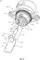
- Figs. 1a - 3 show an embodiment of an interface assembly 10 for an electrical power connector.
- the interface assembly 10 comprises an interface housing 100 and an electrical contact element 200.
- the interface housing 100 comprises a receiving portion 110, which may be adapted to receive at least a part of the electrical contact element 200, in particular a plug-in portion 220 thereof.
- the receiving portion 110 is arranged inside a cavity and may comprise a through hole adapted for receiving the plug-in portion 220 of the electrical contact element 200.
- the plug-in portion 220 maybe connected to a respective electrical element (not shown in Fig. 1 ), e.g. a counter connector, a socket, a cable or others, which may be also mated with the interface housing 100 on a backside, opposite to the shown cavity.
- the interface housing 100 further comprises an essentially cylindrical wall component 120, which encases the cavity and the receiving portion 110 at least partly.
- the axis of the receiving portion 110 and the axis of the essentially cylindrical wall component 120 may coincide and extend in a mating direction 300 of the electrical contact element 200.
- the essentially cylindrical wall component 120 can resemble a segment of a hollow cylinder, in which a centre angle of a base area may range from between 120° and 360° to between 190° and 270°.
- a diameter 121 of the essentially cylindrical wall component 120 may range between 30 mm and 60 mm and the thickness 122 of the essentially cylindrical wall component 120 may be between 1.5 mm and 3 mm.
- the interface housing 100 further comprises two latches 130, 135.
- the two latches 130, 135 can be arranged on an interior surface 141 of the cylindrical wall component 120.
- the two latches 130, 135 may further be arranged on a spring element 133, which is adapted to elastically deflect in a direction 139 perpendicular to the mating direction 300 (s. Fig. 2 ).
- the spring element 133 can be attached to the open edges of the segment of a hollow cylinder, such as e.g. the essentially circular wall component 120.
- the spring element 133 can also be integrally formed with the essentially circular wall component 120, which may provide a cost-efficient manufacture of the spring element 133. It may be noted that to enable deflection of spring element 133, the spring element 133 may be not in contact with the interface housing 100. In contrast, the essentially cylindrical wall component 120 may be arranged in contact with the interface housing 100 at least for the most part.
- the interface housing 100 comprises at least one securing means 150, 151, being formed as a through hole.
- securing means 150, 151 being formed as a through hole.
- two through holes are present.
- securing means are applicable.
- Each of said through holes 150, 151 serves for receiving a further securing element, such as a screw or a bolt, for securing the interface housing 100 to a counterpart (not shown).
- the interface assembly 10 further comprises an electrical contact element 200, which is adapted to transfer electrical power in the range of at least 5 kW up to at least 30 kW, in particular in a higher voltage vehicle system, such as a 48 volts vehicle electrical system.
- the electrical contact element 200 comprises a busbar portion 210, which may resemble a metallic strip or bar.
- Busbar portion 210 comprises said two latching noses 211, 212, which in combination with the two latches 130, 135 are adapted to block a releasement movement of the electrical contact element 200 after mating with the interface housing 100.
- the two latching noses 211, 212 maybe arranged on opposite sides of the busbar portion 210 and may extend perpendicular to the mating direction in a plane of the busbar portion 210.
- the busbar portion 210 further comprises a fixation portion 213, which can be integrally formed with the busbar portion 210 or attached to it separately.
- the fixation portion 213 extends perpendicular to the mating direction 300 and may be formed by bending the respective end of the bus bar portion 210, if both elements are formed integrally.
- the fixation portion 213 has an outer guiding contour 214, which is adapted to fit into a corresponding contour 140 on an interior surface 141 of the interface housing 100 inside the interface cavity.
- the corresponding contour 140 may closely encase the outer guiding contour 214, after mating, to prevent rotations or misplacements of the electrical contact element 200 and allow for a firm fit inside the interface housing 100.
- the electrical contact element 200 further comprises a plug-in portion 220, which is secured to the fixation portion 213.
- the plug-in portion 220 may be secured to the fixation portion 213 by inserting the plug-in portion 220 into a hole of the fixation portion 213. After said inserting, a collar of the plug-in portion 220 may be pressed onto the fixation portion 213 so that a collar area of the plug-in portion 220 may be firmly fixed with the fixation portion 213.
- the plug-in portion 220 has an essentially cylindrical shape and is adapted to be guided into the receiving portion 110 of the interface housing 100.
- a diameter 222 of the plug-in portion 220 may range between 6 mm and 10 mm and a length 221 of the plug-in portion 220 may range between 30 mm and 50 mm.
- Fig. 1a shows the embodiment of the interface assembly
- Fig. 1b illustrates the interface assembly 10 rotated by 180° around the mating direction 300, to allow for a detailed visibility of all components.
- Fig. 2 shows an intermediate state during a mating process
- Fig. 3 illustrates the interface assembly 10 after mating.
- each latch 130, 135 can be adapted to slide along the assigned latching nose 211, 212 during mating.
- an edge of each latch 130, 135 may be belled. Therefore, each latch 130, 135 comprises a first inclined surface 132.
- a surface normal 134 of the first inclined surface 132 points advantageously towards mating direction 300.
- a portion of each latching nose 211, 212, which during mating is sliding along the first inclined surface 132 may also comprise an inclined surface, i.e. the second inclined surface 216. This may provide an improved sliding of the first inclined surface 132 on the second inclined surface 216 during mating which may run essentially parallel.
- Fig. 2 further shows the deflection of the spring element 133 during mating.
- An enlarged section 136 illustrates an exemplary arrangement of the first and second inclined surfaces 132 and 216 during mating.
- the busbar portion 210 further comprises a recess 215.
- the recess 215 is located essentially subsequent to latching noses 211, 212, when seen from the receiving portion 110 along mating direction 300.
- the recess 215 extends in the plane of the busbar portion 210.
- An exemplary arrangement of latch 135 and corresponding latching nose 212 which may similarly, in particular mirror-symmetrically, also represent an arrangement of the latching nose 211 and latch 130, is illustrated in an enlarged section in Fig. 3 . In this manner, each of the latching noses 210, 211 can be received within the recess 215 after mating for efficiently blocking an unintended release movement of the latching noses 210, 211.
- the present embodiment may allow an unlatching of the electrical contact element 200 from the interface housing 100 without breaking of any securing means.
- the latching noses 211, 212 can be released from the latches 130, 135.
- the electrical contact element can be easily removed.
- the latching system can be reused multiple times.
Landscapes
- Details Of Connecting Devices For Male And Female Coupling (AREA)
- Connector Housings Or Holding Contact Members (AREA)
Abstract
Description
- The invention relates to the field of electrical interface assemblies, particularly to interface assemblies for electrical power connectors. Further, the invention relates to an electrical connector. An electrical interface assembly according to the invention, is typically used in vehicles, particularly in the vehicle electrical system.
- During vehicle operation, different electrical consumers, such as e.g. an ignition and fuel-injection system, control units, safety and comfort and convenience electronics, infotainment systems, lighting, and/or other equipment, have to be supplied with power. For powering the electrical consumers, these have to be connected to a power source, such as a vehicle's battery.
- A vehicle electrical system, which may be a closed circuit, connects the single electrical consumers to the respective power source(s) of the vehicle, and thus powers the respective consumers. The consumers and the power source(s) of the vehicle electrical system are typically connected via at least one cable harness. At an electrical interface between two components of the vehicle electrical system (i.e. a consumer, a power source, a cable and/or a cable harness) electrical connectors are typically provided. Conventional vehicle electrical systems run at 12 volts. However, there is a trend to vehicle electrical systems running at higher voltages, such as 42 volts or 48 volts. These higher voltage vehicle electrical systems can be provided instead of or additionally to the conventional vehicle electrical systems that run at 12V.
- Those higher voltage vehicle electrical systems allow to provide more power, compared to conventional 12-volt systems. This is, as e.g. a wire of a given size can carry four times as much power at 48 volts as at 12 volts at the same current (amps).
- Thus, higher voltage vehicle electrical systems allow for lighter cable harnesses, as more power can be transmitted, at a given wire size. Further, the increasing power demand of the vehicle's electrical consumers can be satisfied by establishing higher voltage vehicle electrical systems, as more power can be transferred.
- While conventional 12V-systems may still be used for conventional lighting and infotainment, higher voltage vehicle electrical systems may be used for powering more energy consuming components, such as electrically driven turbochargers, air conditioning, electrical starting assistance systems, and the like. Further, higher voltage vehicle electrical systems allow to provide the electrical energy for electrically powered vehicles, a facilitated recuperation of energy during braking, thereby reducing fuel consumption and CO2 emissions, etc..
- However, with increasing voltage and higher power transmission, the requirements for the electrical interface between two components of the vehicle electrical system increase, i.e. the requirements for electrical connectors and interface assemblies, respectively.
- These increased requirements lead inter alia to increased security measures of the connectors and the interface assemblies. For example, to prevent the risk of electrical shocks, electrostatic shielding is often applied. To further omit unintended loosening of connector-components, e.g. connectors and counter-connectors or cables attached to connectors, in particular if used for power transmission, a firm fixation of these respective components is often required. For example, busbar elements for electrical power distribution from the battery to various consumers are often permanently attached to the interface by pressing the busbar element into a plastic housing. To remove the busbar element, in particular for servicing, at least a part of the plastic housing needs to be broken and replaced by a new plastic housing or a new part of the plastic housing. This leads to a high number of plastic components discarded after a single usage. Further, the time used for replacing various broken parts of the plastic housings during maintenance increases the costs of interval servicing of a car immensely. Thus, there is a need in the art to overcome the aforementioned drawbacks.
- These drawbacks are at least partially overcome by an interface assembly for an electrical power connector and an electrical connector, as defined in the independent claims.
- Particularly, these drawbacks are at least partially overcome by an interface assembly for an electrical power connector comprising an interface housing and an electrical contact element for transferring electrical power. The interface housing comprises a receiving portion arranged inside an interface cavity of the interface housing for receiving an electrical contact element and the interface housing comprises at least two latches. The electrical contact element for transferring electrical power comprises a busbar portion and a plug-in portion, wherein the busbar portion comprises at least two latching noses. Each of the at least two latching noses is assigned to one of the at least two latches to block a release movement of the assigned latching nose upon mating of the electrical contact element and the interface housing.
- In this manner, the present disclosure provides an interface assembly, in which the electrical contact element may be firmly fixed at the interface housing after mating. Additionally, if required for servicing or other reasons, a mechanic or even a similarly skilled person can easily release the electrical contact element from the interface housing by unlatching the at least two latching noses from the respective latches. The latching system according to the present disclosure can thus be reused various times. Moreover, the time needed for servicing may be reduced, since exchanging of single use fixation means can be omitted.
- The interface housing may comprise an essentially cylindrical wall component. By the term "essentially cylindrical" the present disclosure also includes shapes and forms which deviate from a mathematical definition of a cylinder. Therefore, according to the present disclosure, not all points on a cylindrically curved surface, as required e.g. for a mathematically circular cylinder, need to have the same distance, i.e. radius, from a central axis of the cylinder. Small deviations of up to 10 % or similar are still referred to as being essentially cylindrical. Furthermore, elliptical cylinders or portions of a cone, in which an apex is located outside the cone, may also be applicable. Further, the axis of the wall component may extend in mating direction of the electrical contact element. In this manner, the wall component may enclose the interface cavity at least partially. The wall component may be adapted to mechanically and/or electrically shield the interface cavity at least partially.
- The at least two latches can be arranged at the interior surface of the cylindrical wall component. Thus, the at least two latches may be shielded by the cylindrical wall component. Furthermore, in this arrangement an unintended unlatching of the at least two latches may be avoided, or the chances at least reduced compared to latches arranged on an exterior surface.
- In some embodiments of the present disclosure, each of the at least two latches can be arranged on a respective spring element of the cylindrical wall component, that is adapted to elastically deflect in a direction perpendicular to the mating direction. The spring element may be adapted to elastically deflect during mating and/or during un-mating of the electrical contact element and the interface housing. The spring element maybe in contact to the cylindrical wall component. The spring element can optionally be not in contact to the interface housing. Each spring element may be integrally formed with the cylindrical wall component. In this manner, a cost-efficient manufacture of the wall component and the spring element, for example by injection moulding, maybe possible. However, other manufacturing techniques maybe also applicable.
- In some embodiments of the present disclosure, the essentially cylindrical wall component may resemble a segment of a hollow cylinder. A hollow cylinder, as referred to by the present disclosure, may correspond to a shell of a cylinder having a respective thickness. The respective thickness of the shell or the thickness of the essentially cylindrical wall component may range between 1.5 mm and 3 mm. A diameter of the essentially cylindrical wall component may range between 30 mm and 60 mm. The diameter may be determined between two opposite points on the outer surface of the wall component. A centre angle of a base of the hollow cylinder may amount between 120° and 360°, preferably between 180° and 300° and most preferably between 190° and 270°. Thus, the essentially cylindrical wall component may preferably be adapted to not fully encircle the interface cavity but provide open edges. In this manner, the respective spring element can be arranged on the open edge of the cylindrical wall component.
- In some embodiments of the present disclosure, the busbar portion may comprise a fixation portion adapted to hold the plug-in portion. The fixation portion may be attached to the busbar portion or alternatively may be formed integrally with the busbar portion. If the busbar portion and the fixation portion are formed integrally, the fixation portion may be formed by bending one end of the busbar portion. The fixation portion may extend perpendicular to the mating direction. The term perpendicular, as used in the present disclosure, may also include small deviations from exact 90° in the order of 10°. Further the fixation portion may comprise an outer guiding contour, wherein the interface housing may comprise a corresponding contour arranged inside the interface cavity. In this manner, the fixation portion may guide the electrical contact element during mating. Additionally, or alternatively, the fixation portion may be adapted to prevent the electrical contact element from unintentionally rotating within the interface cavity after mating. Moreover, the fixation portion may provide, in combination with the latching system, a firm placement of the electrical contact element within the interface housing at least partially.
- In some embodiments of the present disclosure, the electrical contact element may be adapted to transfer electrical power of at least 5 kW, preferably at least 10 kW, more preferably at least 20 kW and most preferably 30 kW. The electrical contact element may be adapted to transfer electrical power to/or from an electrical consumer, a power source, a cable and/or a cable harness. Particularly, the electrical contact element may be adapted to be used in a higher voltage vehicle electrical system, such as a 48 volts vehicle electrical system.
- In some embodiments of the present disclosure, the at least two latching noses may be arranged on opposite sides of the busbar portion extending perpendicular to the mating direction of the electrical contact element in a plane of the busbar portion. In this manner, the positioning of the at least two latching noses may be advantageously adapted to provide a firm fixation of the electrical contact element inside the interface housing. Further, the latching noses can be integrally formed with the busbar portion, thus providing a cost-efficient manufacture.
- In some embodiments of the present disclosure, a portion of each latch, adapted to slide along the assigned latching nose during mating, may comprise a first inclined surface. The first inclined surface may be adapted to reduce the friction of the latching nose and the latch at least partially. The portion of each latch may be further adapted, so that a surface normal of the first inclined surface points towards mating direction of the electrical contact element.
- In some embodiments of the present disclosure, a portion of each latching nose, assigned to slide along the first inclined surface of the corresponding latch during mating, may comprise a second inclined surface, so that the first inclined surface of the latch and the second inclined surface of the latching nose can be arranged essentially parallel during mating. By providing two essentially parallel surfaces, sliding along of each other, the attrition of the first and second surface may be reduced compared to non-inclined surfaces. The term essentially parallel comprises also small deviations of exact parallel surfaces in the order of 10°. In particular, the term essentially parallel comprises deviations which occur during mating based on an elastically deflection of the at least two latches.
- In some embodiments of the present disclosure, the busbar portion, when seen from the receiving portion along mating direction of the electrical contact element, may comprise a recess subsequent to the latching nose, wherein the recess extends in the plane of the busbar portion and is adapted that the first inclined surface of each of the latches can be received within the recess after mating. In this manner, not only a part of the latching nose may latch into the latch, but also at least a part of the latch, in particular the part comprising the first inclined surface, may latch into the recess. Thus, an improved firm fixation of the electrical contact element and the interface housing may be provided by the present embodiment.
- In some embodiments of the present disclosure, the plug-in portion may comprise an essentially cylindrical shape comprising a diameter perpendicular to the mating direction of the electrical contact element between 6 mm and 10 mm and/or a length in the mating direction between 30 mm and 50 mm. In this manner, the electrical contact element may be adapted by its dimensions to be used in a higher voltage vehicle electrical system, such as a 48 volts vehicle electrical system. The length of the plug-in portion may be defined as reaching from the tip of the plug-in portion until the fixation portion. Further, the provided dimensions of the plug-in portion may comprise optimized dimensions for transferring the required electrical power in a higher voltage vehicle electrical system.
- The above described drawbacks are further at least partially overcome by an electrical connector comprising an interface assembly, as described above, and a housing that houses a plug-in portion of an electrical contacting element at least partly.
- In the following, the figures, which show specific embodiments of the present disclosure, are briefly described.
- Fig. 1a
- schematically shows an interface assembly, in a three-dimensional view;
- Fig. 1b
- schematically shows the interface assembly of
Fig. 1 , rotated by 180° around the mating direction; - Fig. 2
- schematically shows the interface assembly of
Fig. 1 upon mating, including a detail of the latch elements; and - Fig. 3
- schematically shows the interface assembly of
Fig. 1 when mated. - In particular,
Figs. 1a - 3 show an embodiment of aninterface assembly 10 for an electrical power connector. Theinterface assembly 10 comprises aninterface housing 100 and anelectrical contact element 200. - The
interface housing 100 comprises a receivingportion 110, which may be adapted to receive at least a part of theelectrical contact element 200, in particular a plug-inportion 220 thereof. The receivingportion 110 is arranged inside a cavity and may comprise a through hole adapted for receiving the plug-inportion 220 of theelectrical contact element 200. After mating theelectrical contact element 200 and theinterface housing 100, the plug-inportion 220 maybe connected to a respective electrical element (not shown inFig. 1 ), e.g. a counter connector, a socket, a cable or others, which may be also mated with theinterface housing 100 on a backside, opposite to the shown cavity. - The
interface housing 100 further comprises an essentiallycylindrical wall component 120, which encases the cavity and the receivingportion 110 at least partly. The axis of the receivingportion 110 and the axis of the essentiallycylindrical wall component 120 may coincide and extend in amating direction 300 of theelectrical contact element 200. The essentiallycylindrical wall component 120 can resemble a segment of a hollow cylinder, in which a centre angle of a base area may range from between 120° and 360° to between 190° and 270°. Adiameter 121 of the essentiallycylindrical wall component 120 may range between 30 mm and 60 mm and thethickness 122 of the essentiallycylindrical wall component 120 may be between 1.5 mm and 3 mm. - The
interface housing 100 further comprises twolatches interior surface 141 of thecylindrical wall component 120. The two latches 130, 135 may further be arranged on aspring element 133, which is adapted to elastically deflect in adirection 139 perpendicular to the mating direction 300 (s.Fig. 2 ). Thespring element 133 can be attached to the open edges of the segment of a hollow cylinder, such as e.g. the essentiallycircular wall component 120. Alternatively, thespring element 133 can also be integrally formed with the essentiallycircular wall component 120, which may provide a cost-efficient manufacture of thespring element 133. It may be noted that to enable deflection ofspring element 133, thespring element 133 may be not in contact with theinterface housing 100. In contrast, the essentiallycylindrical wall component 120 may be arranged in contact with theinterface housing 100 at least for the most part. - The
interface housing 100 comprises at least one securing means 150, 151, being formed as a through hole. In the embodiment illustrated in the Figures, two through holes are present. However, also different numbers of securing means are applicable. Each of said throughholes interface housing 100 to a counterpart (not shown). - The
interface assembly 10 further comprises anelectrical contact element 200, which is adapted to transfer electrical power in the range of at least 5 kW up to at least 30 kW, in particular in a higher voltage vehicle system, such as a 48 volts vehicle electrical system. Theelectrical contact element 200 comprises abusbar portion 210, which may resemble a metallic strip or bar.Busbar portion 210 comprises said two latchingnoses latches electrical contact element 200 after mating with theinterface housing 100. The two latchingnoses busbar portion 210 and may extend perpendicular to the mating direction in a plane of thebusbar portion 210. - The
busbar portion 210 further comprises afixation portion 213, which can be integrally formed with thebusbar portion 210 or attached to it separately. Thefixation portion 213 extends perpendicular to themating direction 300 and may be formed by bending the respective end of thebus bar portion 210, if both elements are formed integrally. Thefixation portion 213 has anouter guiding contour 214, which is adapted to fit into acorresponding contour 140 on aninterior surface 141 of theinterface housing 100 inside the interface cavity. The correspondingcontour 140 may closely encase theouter guiding contour 214, after mating, to prevent rotations or misplacements of theelectrical contact element 200 and allow for a firm fit inside theinterface housing 100. - The
electrical contact element 200 further comprises a plug-inportion 220, which is secured to thefixation portion 213. For example, the plug-inportion 220 may be secured to thefixation portion 213 by inserting the plug-inportion 220 into a hole of thefixation portion 213. After said inserting, a collar of the plug-inportion 220 may be pressed onto thefixation portion 213 so that a collar area of the plug-inportion 220 may be firmly fixed with thefixation portion 213. The plug-inportion 220 has an essentially cylindrical shape and is adapted to be guided into the receivingportion 110 of theinterface housing 100. Adiameter 222 of the plug-inportion 220 may range between 6 mm and 10 mm and alength 221 of the plug-inportion 220 may range between 30 mm and 50 mm. - While
Fig. 1a shows the embodiment of theinterface assembly 10,Fig. 1b illustrates theinterface assembly 10 rotated by 180° around themating direction 300, to allow for a detailed visibility of all components. To further illustrate a mating of theinterface housing 100 with theelectrical contact element 200,Fig. 2 shows an intermediate state during a mating process, whileFig. 3 illustrates theinterface assembly 10 after mating. - In some embodiments of the present disclosure, each
latch nose latch latch inclined surface 132. A surface normal 134 of the firstinclined surface 132 points advantageously towardsmating direction 300. Similarly, a portion of each latchingnose inclined surface 132, may also comprise an inclined surface, i.e. the secondinclined surface 216. This may provide an improved sliding of the firstinclined surface 132 on the secondinclined surface 216 during mating which may run essentially parallel.Fig. 2 further shows the deflection of thespring element 133 during mating. Anenlarged section 136 illustrates an exemplary arrangement of the first and secondinclined surfaces - In some embodiments of the present disclosure, the
busbar portion 210 further comprises arecess 215. Therecess 215 is located essentially subsequent to latchingnoses portion 110 alongmating direction 300. Therecess 215 extends in the plane of thebusbar portion 210. An exemplary arrangement oflatch 135 and corresponding latchingnose 212, which may similarly, in particular mirror-symmetrically, also represent an arrangement of the latchingnose 211 andlatch 130, is illustrated in an enlarged section inFig. 3 . In this manner, each of the latchingnoses recess 215 after mating for efficiently blocking an unintended release movement of the latchingnoses electrical contact element 200 from theinterface housing 100 without breaking of any securing means. By intentionally deflecting thelatches direction 139 perpendicular to themating direction 300, the latchingnoses latches -
- 10
- interface assembly
- 100
- interface housing
- 110
- receiving portion
- 120
- cylindrical wall component
- 121
- diameter of the cylindrical wall component
- 122
- thickness of the cylindrical wall component
- 130,135
- latch
- 132
- first inclined surface
- 133
- spring element
- 134
- surface normal
- 136
- enlarged section
- 139
- deflection direction
- 140
- corresponding contour
- 141
- interior surface
- 150, 151
- securing means
- 200
- electrical contact element
- 210
- busbar portion
- 211, 212
- latching nose
- 213
- fixation portion
- 214
- outer contour
- 215
- recess
- 216
- second inclined surface
- 220
- plug-in portion
- 221
- length of the plug-in portion
- 222
- diameter of the plug-in portion
- 300
- mating direction
Claims (15)
- An interface assembly (10) for an electrical power connector, comprising:an interface housing (100) comprising a receiving portion (110) arranged inside an interface cavity of the interface housing (100), for receiving an electrical contact element (200), the interface housing (100) further comprising at least two latches (130, 135); andan electrical contact element (200) for transferring electrical power comprising a busbar portion (210) and a plug-in portion (220),wherein the busbar portion (210) comprises at least two latching noses (211, 212), andwherein each of the at least two latching noses (211, 212) is assigned to one of the at least two latches (130, 135) to block a release movement of the assigned latching nose (211, 212) upon mating of the electrical contact element (200) and the interface housing (100).
- The interface assembly (10) according to the preceding claim, wherein the interface housing (100) further comprises an essentially cylindrical wall component (120), the axis of which extends in a mating direction (300) of the electrical contact element (200).
- The interface assembly (10) according to the preceding claim, wherein the at least two latches (130, 135) are arranged at an interior surface (141) of the cylindrical wall component (120).
- The interface assembly (10) according to the preceding claim, wherein each of the at least two latches (130, 135) is arranged on a respective spring element (133) of the cylindrical wall component (120), that is adapted to elastically deflect in a direction (139) perpendicular to the mating direction (300).
- The interface assembly (10) according to the preceding claim, wherein the respective spring element (133) is integrally formed with the cylindrical wall component (120).
- The interface assembly (10) according to any of claims 2 - 5, wherein the essentially cylindrical wall component (120) resembles a segment of a hollow cylinder, wherein a centre angle of a base of the hollow cylinder is between 120° and 360°, preferably between 180° and 300° and most preferably between 190° and 270°; and wherein the respective spring element (133) is arranged on an open edge of the cylindrical wall component (120).
- The interface assembly (10) according to any preceding claim, wherein the busbar portion (210) comprises a fixation portion (213) adapted to hold the plug-in portion (220), the fixation portion (213) extends perpendicular to the mating direction (300) and comprises an outer guiding contour (214), wherein the interface housing (100) comprises a corresponding contour (140) arranged inside the interface cavity.
- The interface assembly (10) according to any preceding claim, wherein the electrical contact element (200) is adapted to transfer electrical power of at least 5 kW, preferably at least 10 kW, more preferably at least 20 kW and most preferably 30 kW.
- The interface assembly (10) according to any of claims 2 - 8, wherein the essentially cylindrical wall component (120) comprises a diameter (121) between 30 mm and 60 mm and/or a thickness (122) of the wall component between 1.5 mm and 3 mm.
- The interface assembly (10) according to any preceding claim, wherein the at least two latching noses (211, 212) are arranged on opposite sides of the busbar portion (210) extending perpendicular to the mating direction (300) of the electrical contact element (200) in a plane of the busbar portion (210).
- The interface assembly (10) according to any preceding claim, wherein a portion of each latch (130, 135), adapted to slide along the assigned latching nose (211, 212) during mating, comprises a first inclined surface (132), so that a surface normal (134) of the first inclined surface (132) points towards mating direction (300) of the electrical contact element (200).
- The interface assembly (10) according to the preceding claim, wherein a portion of each latching nose (211, 212), assigned to slide along the first inclined surface (132) of the corresponding latch (130, 135) during mating, comprises a second inclined surface (216), so that the first inclined surface (132) of the latch (130, 135) and the second inclined surface (216) of the latching nose (211, 212) are arranged essentially parallel during mating.
- The interface assembly (10) according to any of claims 11 - 12, wherein the busbar portion (120), when seen from the receiving portion (110) along mating direction (300) of the electrical contact element (200), comprises a recess (215) subsequent to the latching nose (211, 212), wherein the recess (215) extends in the plane of the busbar portion (210) and is adapted that the first inclined surface (132) of each of the latches (130, 135) can be received within the recess (215) after mating.
- The interface assembly (10) according to any preceding claim, wherein the plug-in portion (220) comprises an essentially cylindrical shape comprising a diameter (222) perpendicular to mating direction (300) of the electrical contact element (200) between 6 mm and 10 mm and/or a length (221) in mating direction (300) between 30 mm and 50 mm.
- An electrical connector, comprising an interface assembly (10) according to any preceding claim and a housing that houses a plug-in portion (220) of an electrical contacting element (200) at least partly.
Applications Claiming Priority (1)
| Application Number | Priority Date | Filing Date | Title |
|---|---|---|---|
| DE102020206618.3A DE102020206618A1 (en) | 2020-05-27 | 2020-05-27 | ELECTRICAL INTERFACE ARRANGEMENT |
Publications (1)
| Publication Number | Publication Date |
|---|---|
| EP3916922A1 true EP3916922A1 (en) | 2021-12-01 |
Family
ID=75977614
Family Applications (1)
| Application Number | Title | Priority Date | Filing Date |
|---|---|---|---|
| EP21174236.6A Pending EP3916922A1 (en) | 2020-05-27 | 2021-05-18 | Electrical interface assembly |
Country Status (3)
| Country | Link |
|---|---|
| US (1) | US11588275B2 (en) |
| EP (1) | EP3916922A1 (en) |
| DE (1) | DE102020206618A1 (en) |
Cited By (1)
| Publication number | Priority date | Publication date | Assignee | Title |
|---|---|---|---|---|
| CN114899635A (en) * | 2022-07-13 | 2022-08-12 | 深圳智慧龙城软件开发技术有限公司 | Electronic product interface protector |
Citations (3)
| Publication number | Priority date | Publication date | Assignee | Title |
|---|---|---|---|---|
| US20090098779A1 (en) * | 2007-10-12 | 2009-04-16 | Sumitomo Wiring Systems, Ltd. | connector |
| CN209200228U (en) * | 2018-12-07 | 2019-08-02 | 深圳巴斯巴科技发展有限公司 | A kind of soft or hard copper bar connecting structure of novel connector body |
| CN210430174U (en) * | 2019-11-20 | 2020-04-28 | 公牛集团股份有限公司 | Detachable bolt assembly and plug |
Family Cites Families (7)
| Publication number | Priority date | Publication date | Assignee | Title |
|---|---|---|---|---|
| US4187272A (en) * | 1976-10-01 | 1980-02-05 | The Bendix Corporation | Method of making molded electrical connector insert |
| US4364621A (en) * | 1980-02-28 | 1982-12-21 | General Signal Corp. | Electrical connector |
| US4374604A (en) | 1981-03-05 | 1983-02-22 | The Bendix Corporation | Contact for an electrical connector |
| JP5095446B2 (en) * | 2008-03-05 | 2012-12-12 | 矢崎総業株式会社 | connector |
| CN202142747U (en) | 2011-03-17 | 2012-02-08 | 深圳市电连精密技术有限公司 | Improved coaxial connector socket |
| US10340618B1 (en) * | 2017-12-19 | 2019-07-02 | Lear Corporation | Electrical terminal housing with releasable terminal locks |
| US10396485B1 (en) * | 2018-04-05 | 2019-08-27 | Delphi Technologies, Llc | Electrical connector assembly |
-
2020
- 2020-05-27 DE DE102020206618.3A patent/DE102020206618A1/en active Pending
-
2021
- 2021-05-18 EP EP21174236.6A patent/EP3916922A1/en active Pending
- 2021-05-26 US US17/330,800 patent/US11588275B2/en active Active
Patent Citations (3)
| Publication number | Priority date | Publication date | Assignee | Title |
|---|---|---|---|---|
| US20090098779A1 (en) * | 2007-10-12 | 2009-04-16 | Sumitomo Wiring Systems, Ltd. | connector |
| CN209200228U (en) * | 2018-12-07 | 2019-08-02 | 深圳巴斯巴科技发展有限公司 | A kind of soft or hard copper bar connecting structure of novel connector body |
| CN210430174U (en) * | 2019-11-20 | 2020-04-28 | 公牛集团股份有限公司 | Detachable bolt assembly and plug |
Cited By (1)
| Publication number | Priority date | Publication date | Assignee | Title |
|---|---|---|---|---|
| CN114899635A (en) * | 2022-07-13 | 2022-08-12 | 深圳智慧龙城软件开发技术有限公司 | Electronic product interface protector |
Also Published As
| Publication number | Publication date |
|---|---|
| US11588275B2 (en) | 2023-02-21 |
| US20210376523A1 (en) | 2021-12-02 |
| DE102020206618A1 (en) | 2021-12-02 |
Similar Documents
| Publication | Publication Date | Title |
|---|---|---|
| JP6543731B2 (en) | Charging connector and method of manufacturing charging connector assembly | |
| CN108631090B (en) | car charging plug-in connector | |
| US8333613B2 (en) | Header assembly | |
| CN103038948B (en) | Electrical connection busbar | |
| EP2719024B1 (en) | Connector | |
| US6695632B2 (en) | Shield connector | |
| US20220376423A1 (en) | Charging connector for vehicle | |
| US20240063584A1 (en) | Electrical High-Current Connector | |
| US9705225B1 (en) | Electrical connector assembly having a plurality of electrical socket terminals retained within a socket cartridge | |
| CN112151995A (en) | plug connector | |
| CN112585831B (en) | Retainer and harness | |
| US11588275B2 (en) | Electrical interface assembly | |
| CN115986498A (en) | Electrical plug connector for a bus bar | |
| EP3849024A1 (en) | Rotatable interface assembly for an electrical connector | |
| US12431662B2 (en) | Shielding element and plug connector | |
| CN121002737A (en) | High-power plug connector system | |
| CN113809582B (en) | Connector housing and connector assembly for electrical connector | |
| CN109346895A (en) | Plug connector and battery pack and vehicle with it | |
| EP4283789A1 (en) | Electrical safety connector | |
| US20260106400A1 (en) | High voltage condcutor assembly for an electrical device | |
| CN116114121B (en) | connector | |
| US20100130052A1 (en) | Electrical connector | |
| US20260128555A1 (en) | Connector structure | |
| KR20250016649A (en) | Connector of vehicle | |
| CN116235368A (en) | contact carrier |
Legal Events
| Date | Code | Title | Description |
|---|---|---|---|
| PUAI | Public reference made under article 153(3) epc to a published international application that has entered the european phase |
Free format text: ORIGINAL CODE: 0009012 |
|
| STAA | Information on the status of an ep patent application or granted ep patent |
Free format text: STATUS: THE APPLICATION HAS BEEN PUBLISHED |
|
| AK | Designated contracting states |
Kind code of ref document: A1 Designated state(s): AL AT BE BG CH CY CZ DE DK EE ES FI FR GB GR HR HU IE IS IT LI LT LU LV MC MK MT NL NO PL PT RO RS SE SI SK SM TR |
|
| B565 | Issuance of search results under rule 164(2) epc |
Effective date: 20211021 |
|
| STAA | Information on the status of an ep patent application or granted ep patent |
Free format text: STATUS: REQUEST FOR EXAMINATION WAS MADE |
|
| 17P | Request for examination filed |
Effective date: 20220530 |
|
| RBV | Designated contracting states (corrected) |
Designated state(s): AL AT BE BG CH CY CZ DE DK EE ES FI FR GB GR HR HU IE IS IT LI LT LU LV MC MK MT NL NO PL PT RO RS SE SI SK SM TR |
|
| RAP3 | Party data changed (applicant data changed or rights of an application transferred) |
Owner name: APTIV TECHNOLOGIES LIMITED |
|
| STAA | Information on the status of an ep patent application or granted ep patent |
Free format text: STATUS: EXAMINATION IS IN PROGRESS |
|
| 17Q | First examination report despatched |
Effective date: 20230907 |
|
| RAP1 | Party data changed (applicant data changed or rights of an application transferred) |
Owner name: APTIV TECHNOLOGIES AG |
|
| RAP3 | Party data changed (applicant data changed or rights of an application transferred) |
Owner name: APTIV TECHNOLOGIES AG |
|
| GRAP | Despatch of communication of intention to grant a patent |
Free format text: ORIGINAL CODE: EPIDOSNIGR1 |
|
| STAA | Information on the status of an ep patent application or granted ep patent |
Free format text: STATUS: GRANT OF PATENT IS INTENDED |
|
| RIC1 | Information provided on ipc code assigned before grant |
Ipc: H01R 11/28 20060101AFI20260226BHEP Ipc: H01R 13/428 20060101ALI20260226BHEP Ipc: H01R 13/422 20060101ALI20260226BHEP Ipc: H01R 11/05 20060101ALI20260226BHEP Ipc: H01R 13/04 20060101ALI20260226BHEP Ipc: H01R 101/00 20060101ALN20260226BHEP |
|
| INTG | Intention to grant announced |
Effective date: 20260311 |