EP3916865A1 - Secondary battery having structure in which unit cells which become thinner in one direction are radially assembled, and device comprising same - Google Patents
Secondary battery having structure in which unit cells which become thinner in one direction are radially assembled, and device comprising same Download PDFInfo
- Publication number
- EP3916865A1 EP3916865A1 EP20878093.2A EP20878093A EP3916865A1 EP 3916865 A1 EP3916865 A1 EP 3916865A1 EP 20878093 A EP20878093 A EP 20878093A EP 3916865 A1 EP3916865 A1 EP 3916865A1
- Authority
- EP
- European Patent Office
- Prior art keywords
- secondary battery
- battery
- positive electrode
- unit cell
- negative electrode
- Prior art date
- Legal status (The legal status is an assumption and is not a legal conclusion. Google has not performed a legal analysis and makes no representation as to the accuracy of the status listed.)
- Granted
Links
Images


Classifications
-
- H—ELECTRICITY
- H01—ELECTRIC ELEMENTS
- H01M—PROCESSES OR MEANS, e.g. BATTERIES, FOR THE DIRECT CONVERSION OF CHEMICAL ENERGY INTO ELECTRICAL ENERGY
- H01M10/00—Secondary cells; Manufacture thereof
- H01M10/04—Construction or manufacture in general
-
- H—ELECTRICITY
- H01—ELECTRIC ELEMENTS
- H01M—PROCESSES OR MEANS, e.g. BATTERIES, FOR THE DIRECT CONVERSION OF CHEMICAL ENERGY INTO ELECTRICAL ENERGY
- H01M10/00—Secondary cells; Manufacture thereof
- H01M10/04—Construction or manufacture in general
- H01M10/0463—Cells or batteries with horizontal or inclined electrodes
-
- H—ELECTRICITY
- H01—ELECTRIC ELEMENTS
- H01M—PROCESSES OR MEANS, e.g. BATTERIES, FOR THE DIRECT CONVERSION OF CHEMICAL ENERGY INTO ELECTRICAL ENERGY
- H01M10/00—Secondary cells; Manufacture thereof
- H01M10/05—Accumulators with non-aqueous electrolyte
- H01M10/052—Li-accumulators
-
- H—ELECTRICITY
- H01—ELECTRIC ELEMENTS
- H01M—PROCESSES OR MEANS, e.g. BATTERIES, FOR THE DIRECT CONVERSION OF CHEMICAL ENERGY INTO ELECTRICAL ENERGY
- H01M4/00—Electrodes
- H01M4/02—Electrodes composed of, or comprising, active material
- H01M4/64—Carriers or collectors
- H01M4/66—Selection of materials
- H01M4/661—Metal or alloys, e.g. alloy coatings
-
- H—ELECTRICITY
- H01—ELECTRIC ELEMENTS
- H01M—PROCESSES OR MEANS, e.g. BATTERIES, FOR THE DIRECT CONVERSION OF CHEMICAL ENERGY INTO ELECTRICAL ENERGY
- H01M4/00—Electrodes
- H01M4/02—Electrodes composed of, or comprising, active material
- H01M4/64—Carriers or collectors
- H01M4/70—Carriers or collectors characterised by shape or form
- H01M4/72—Grids
- H01M4/74—Meshes or woven material; Expanded metal
-
- H—ELECTRICITY
- H01—ELECTRIC ELEMENTS
- H01M—PROCESSES OR MEANS, e.g. BATTERIES, FOR THE DIRECT CONVERSION OF CHEMICAL ENERGY INTO ELECTRICAL ENERGY
- H01M4/00—Electrodes
- H01M4/02—Electrodes composed of, or comprising, active material
- H01M4/64—Carriers or collectors
- H01M4/70—Carriers or collectors characterised by shape or form
- H01M4/72—Grids
- H01M4/74—Meshes or woven material; Expanded metal
- H01M4/745—Expanded metal
-
- H—ELECTRICITY
- H01—ELECTRIC ELEMENTS
- H01M—PROCESSES OR MEANS, e.g. BATTERIES, FOR THE DIRECT CONVERSION OF CHEMICAL ENERGY INTO ELECTRICAL ENERGY
- H01M4/00—Electrodes
- H01M4/02—Electrodes composed of, or comprising, active material
- H01M4/64—Carriers or collectors
- H01M4/70—Carriers or collectors characterised by shape or form
- H01M4/80—Porous plates, e.g. sintered carriers
-
- H—ELECTRICITY
- H01—ELECTRIC ELEMENTS
- H01M—PROCESSES OR MEANS, e.g. BATTERIES, FOR THE DIRECT CONVERSION OF CHEMICAL ENERGY INTO ELECTRICAL ENERGY
- H01M50/00—Constructional details or processes of manufacture of the non-active parts of electrochemical cells other than fuel cells, e.g. hybrid cells
- H01M50/20—Mountings; Secondary casings or frames; Racks, modules or packs; Suspension devices; Shock absorbers; Transport or carrying devices; Holders
- H01M50/204—Racks, modules or packs for multiple batteries or multiple cells
- H01M50/207—Racks, modules or packs for multiple batteries or multiple cells characterised by their shape
-
- H—ELECTRICITY
- H01—ELECTRIC ELEMENTS
- H01M—PROCESSES OR MEANS, e.g. BATTERIES, FOR THE DIRECT CONVERSION OF CHEMICAL ENERGY INTO ELECTRICAL ENERGY
- H01M50/00—Constructional details or processes of manufacture of the non-active parts of electrochemical cells other than fuel cells, e.g. hybrid cells
- H01M50/20—Mountings; Secondary casings or frames; Racks, modules or packs; Suspension devices; Shock absorbers; Transport or carrying devices; Holders
- H01M50/249—Mountings; Secondary casings or frames; Racks, modules or packs; Suspension devices; Shock absorbers; Transport or carrying devices; Holders specially adapted for aircraft or vehicles, e.g. cars or trains
-
- H—ELECTRICITY
- H01—ELECTRIC ELEMENTS
- H01M—PROCESSES OR MEANS, e.g. BATTERIES, FOR THE DIRECT CONVERSION OF CHEMICAL ENERGY INTO ELECTRICAL ENERGY
- H01M50/00—Constructional details or processes of manufacture of the non-active parts of electrochemical cells other than fuel cells, e.g. hybrid cells
- H01M50/20—Mountings; Secondary casings or frames; Racks, modules or packs; Suspension devices; Shock absorbers; Transport or carrying devices; Holders
- H01M50/258—Modular batteries; Casings provided with means for assembling
-
- H—ELECTRICITY
- H01—ELECTRIC ELEMENTS
- H01M—PROCESSES OR MEANS, e.g. BATTERIES, FOR THE DIRECT CONVERSION OF CHEMICAL ENERGY INTO ELECTRICAL ENERGY
- H01M4/00—Electrodes
- H01M4/02—Electrodes composed of, or comprising, active material
- H01M2004/021—Physical characteristics, e.g. porosity, surface area
-
- H—ELECTRICITY
- H01—ELECTRIC ELEMENTS
- H01M—PROCESSES OR MEANS, e.g. BATTERIES, FOR THE DIRECT CONVERSION OF CHEMICAL ENERGY INTO ELECTRICAL ENERGY
- H01M4/00—Electrodes
- H01M4/02—Electrodes composed of, or comprising, active material
- H01M2004/025—Electrodes composed of, or comprising, active material with shapes other than plane or cylindrical
-
- H—ELECTRICITY
- H01—ELECTRIC ELEMENTS
- H01M—PROCESSES OR MEANS, e.g. BATTERIES, FOR THE DIRECT CONVERSION OF CHEMICAL ENERGY INTO ELECTRICAL ENERGY
- H01M2220/00—Batteries for particular applications
- H01M2220/10—Batteries in stationary systems, e.g. emergency power source in plant
-
- H—ELECTRICITY
- H01—ELECTRIC ELEMENTS
- H01M—PROCESSES OR MEANS, e.g. BATTERIES, FOR THE DIRECT CONVERSION OF CHEMICAL ENERGY INTO ELECTRICAL ENERGY
- H01M2220/00—Batteries for particular applications
- H01M2220/20—Batteries in motive systems, e.g. vehicle, ship, plane
-
- H—ELECTRICITY
- H01—ELECTRIC ELEMENTS
- H01M—PROCESSES OR MEANS, e.g. BATTERIES, FOR THE DIRECT CONVERSION OF CHEMICAL ENERGY INTO ELECTRICAL ENERGY
- H01M2220/00—Batteries for particular applications
- H01M2220/30—Batteries in portable systems, e.g. mobile phone, laptop
-
- Y—GENERAL TAGGING OF NEW TECHNOLOGICAL DEVELOPMENTS; GENERAL TAGGING OF CROSS-SECTIONAL TECHNOLOGIES SPANNING OVER SEVERAL SECTIONS OF THE IPC; TECHNICAL SUBJECTS COVERED BY FORMER USPC CROSS-REFERENCE ART COLLECTIONS [XRACs] AND DIGESTS
- Y02—TECHNOLOGIES OR APPLICATIONS FOR MITIGATION OR ADAPTATION AGAINST CLIMATE CHANGE
- Y02E—REDUCTION OF GREENHOUSE GAS [GHG] EMISSIONS, RELATED TO ENERGY GENERATION, TRANSMISSION OR DISTRIBUTION
- Y02E60/00—Enabling technologies; Technologies with a potential or indirect contribution to GHG emissions mitigation
- Y02E60/10—Energy storage using batteries
-
- Y—GENERAL TAGGING OF NEW TECHNOLOGICAL DEVELOPMENTS; GENERAL TAGGING OF CROSS-SECTIONAL TECHNOLOGIES SPANNING OVER SEVERAL SECTIONS OF THE IPC; TECHNICAL SUBJECTS COVERED BY FORMER USPC CROSS-REFERENCE ART COLLECTIONS [XRACs] AND DIGESTS
- Y02—TECHNOLOGIES OR APPLICATIONS FOR MITIGATION OR ADAPTATION AGAINST CLIMATE CHANGE
- Y02P—CLIMATE CHANGE MITIGATION TECHNOLOGIES IN THE PRODUCTION OR PROCESSING OF GOODS
- Y02P70/00—Climate change mitigation technologies in the production process for final industrial or consumer products
- Y02P70/50—Manufacturing or production processes characterised by the final manufactured product
Definitions
- the present invention relates to a secondary battery including a structure in which unit cells whose thickness decreases in one direction are radially assembled, and a device including the same.
- lithium ions in an electrolyte solution generally exhibit high ion conductivity in a specific concentration range, and when the concentration is thinner or thicker than this, the ion conductivity decreases.
- concentration of electrolyte solution or lithium ions inside the lithium secondary battery is not constant, and depending on the operating conditions of the battery, the concentrations of lithium ions near the positive electrode and the negative electrode behave in opposite directions.
- the present invention was invented to solve the above problems, and an object of the present invention is to provide a new type of secondary battery including a structure in which unit cells whose thickness decreases in one direction are radially assembled, and a device including the same.
- a secondary battery according to the present invention is formed as n (n is an integer of 5 or more) unit cells are radially assembled around a central axis based on a horizontal cross-sectional structure.
- each unit cell has a structure in which a thickness decreases in a direction toward the central axis from an outer end that forms an outer peripheral surface of the secondary battery based on the horizontal cross-sectional structure.
- a k-th (k is an integer between 1 and n-1) unit cell and a (k+1)-th unit cell are adjacent to each other and face each other.
- a first unit cell and an n-th (n is an integer between 5 and 10000) unit cell are also adjacent to each other and face each other.
- the n value may vary depending on the size of the device to be applied. For mobile or small devices, n may be 1000 or less, and in the case of large cells for vehicles, etc., the unit cells may be aggregated in the range of 1000 to 10000.
- the secondary battery has a cylindrical structure in which n unit cells are radially assembled around the central axis to form a hollow based on the horizontal cross-sectional structure, wherein the n is an integer of 5 or more, and wherein a diameter ratio of inner and outer diameters of the secondary battery is in a range of 1 : 1.1 to 100.
- the ratio (D in : D out ) of the thickness (D in ) of the inner end forming the inner peripheral surface of the battery in the center direction and the thickness (D out ) of the outer end forming the outer peripheral surface of the battery is in the range of 1 : 1.1 to 100, based on the horizontal cross-sectional structure.
- At least one of a positive electrode and a negative electrode has a structure in which a distance between electrodes decreases in a center direction from the outer end that forms an outer peripheral surface of the battery based on the horizontal cross-sectional structure.
- each unit cell comprises a positive electrode and a negative electrode
- each of the positive electrode and the negative electrode has a structure in which a mixture layer including an active material is applied on a metal current collector
- at least one of the positive electrode or the negative electrode has a structure in which a thickness of the mixture layer applied on the metal current collector decreases in a direction toward the central axis from the outer end that forms the outer peripheral surface of the battery, based on the horizontal section structure.
- At least one of the positive electrode or the negative electrode has a structure in which a density of the mixture layer increases in a direction toward the central axis from the outer end that forms the outer peripheral surface of the battery, based on the horizontal section structure.
- each unit cell includes a positive electrode and a negative electrode, and a first separator is interposed between the positive electrode and the negative electrode, and wherein a second separator is interposed between the unit cells.
- each of the positive electrode and the negative electrode includes: a current collector; and a mixture layer including an active material disposed on the current collector one a surface facing the first separator.
- At least one of a positive electrode or a negative electrode includes a metal current collector having a porous structure in which through holes are formed in a thickness direction.
- a metal current collector forming at least one of a positive electrode and a negative electrode has a porous structure in which a through-thickness hole is formed, and an area ratio of the through holes on a surface of the metal current collector is in a range of 10 to 80%.
- the metal current collector having the porous structure is in a form of a mesh.
- the present invention provides a device including the above-described secondary battery.
- the device may include a mobile device, a wearable device, a power tool that moves by receiving power by a battery-based motor, a drone, or an Electric Vehicle (EV), a Hybrid Electric Vehicle (HEV), a Plug-in Hybrid Electric Vehicle (PHEV), an Electric Bike (E-bike), an Electric Scooter (E-scooter), an Electric Golf Cart (electric golf cart) or a power storage system.
- EV Electric Vehicle
- HEV Hybrid Electric Vehicle
- PHEV Plug-in Hybrid Electric Vehicle
- E-bike Electric Bike
- E-scooter Electric Golf Cart
- Electric Golf Cart electric golf cart
- a secondary battery and a device including the same propose a new structure in which unit cells whose thickness decreases in one direction are radially assembled, and when a current collector with a through-type hole formed in the thickness direction is applied, the variation in concentration of the electrolyte solution in the battery can be reduced, thereby improving battery performance.
- the cross-sectional shape of a battery is n-gonal shaped, if n is 5 or more, or 10 or more, it should be interpreted as being included in the circular category.
- n (n is an integer of 5 or more) unit cells are radially assembled around a central axis to form a battery.
- each unit cell provides a secondary battery having a structure in which a cell thickness decreases in a direction of a central axis from an outer end forming an outer peripheral surface of the battery based on a horizontal cross-sectional structure.
- a plurality of unit cells are radially assembled to form a battery.
- the shape of the secondary battery may have a circular shape or a shape close to it, an n-gonal shape, or a fan shape, based on a horizontal cross-sectional structure.
- the number n of unit cells collected in the secondary battery is an integer of 5 or more, and specifically in the range of 5 to 10000, 5 to 100, 100 to 1000, 1000 to 10000, 500 to 5000, or 3000 to 10000.
- the number n of the unit cells can be variously designed according to the shape, structure, or required physical properties of the battery.
- the k-th (k is an integer between 1 and n-1) unit cell and the k+1-th unit cell are adjacent to each other and face each other.
- the first unit cell and the n-th unit cell (n is an integer between 5 and 10000) are also adjacent to each other and face each other.
- a plurality of unit cells may be radially assembled to form a cylindrical structure.
- the outer peripheral surface of the cylindrical structure is determined by the number of unit cells, and a circular or n-gonal shape can be formed based on the cross section.
- the secondary battery may have a structure in which a hollow penetrating in a vertical direction is formed in the center of the secondary battery as a whole and the exterior has a cylindrical shape.
- the secondary battery has a cylindrical structure in which n unit cells (n is an integer of 5 or more) are radially aggregated around a central axis to form a hollow based on a horizontal cross-sectional structure.
- the secondary battery has a diameter ratio of an inner diameter and an outer diameter of 1 : 1.1 to 100. The diameter ratio of the inner diameter and the outer diameter of the secondary battery is calculated based on the average values of the inner diameters and the outer diameters, respectively.
- the secondary battery has a diameter ratio of the inner diameter and the outer diameter of the battery in the range of 1 : 1.1 to 100, 1 : 1.5 to 80, 1 : 2 to 50, 1 : 10 to 100, or 1 : 30 to 100.
- the ratio (D in : D out ) of the thickness (D in ) of the inner end forming the inner peripheral surface of the battery in the center direction and the thickness (D out ) of the outer end forming the outer peripheral surface of the battery is in the range of 1 : 1.5 to 10, based on the horizontal section structure.
- the ratio (D in : D out ) is in the range of 1 : 1.1 to 100, 1 : 1.5 to 80, 1 : 2 to 50, 1 : 10 to 100, or 1 : 30 to 100.
- the unit cell included in the secondary battery according to the present invention has a shape in which the thickness decreases in one direction.
- This is a form differentiated from conventional prismatic batteries, pouch-type batteries, or cylindrical batteries.
- Existing secondary batteries have a difference in external shape, but unit cells constituting each battery are manufactured with a uniform overall thickness, but are merely different in a stacked form or a winding form.
- at least one of the positive electrode and the negative electrode has a structure in which the distance between the electrodes decreases in the center direction from the outer end that forms the outer peripheral surface of the battery based on the horizontal cross-sectional structure.
- a secondary battery applicable to various types of devices can be manufactured.
- a secondary battery that can be stored inside the watch band may be applied.
- the watch band may be formed in a form in which a straight section area and a curved section area are combined.
- a secondary battery having a structure in which unit cells of uniform thickness are assembled in the straight section area of the watch band and unit cells whose thickness decreases in one direction are assembled in the curved section area a secondary battery of a desired shape can be easily manufactured.
- a positive electrode and a negative electrode each have a structure in which a mixture layer including an active material is applied on a metal current collector. Further, at least one of the positive electrode and the negative electrode has a structure in which the thickness of the mixture layer applied on the metal current collector decreases in the direction of the central axis at the outer end forming the outer peripheral surface of the battery based on the horizontal cross-sectional structure. That is, the present invention is designed to increase or decrease the thickness of the material mixture layer loaded on the current collector in one direction, thereby imparting thickness orientation to the unit cell.
- a positive electrode and a negative electrode each have a structure in which a mixture layer including an active material is applied on a metal current collector. Further, at least one of the positive electrode and the negative electrode has a structure in which the density of the mixture layer applied on the metal current collector increases in the direction of the central axis from the outer end forming the outer peripheral surface of the battery based on the horizontal cross-sectional structure. As described above, when the present invention is designed to increase or decrease the thickness of the material mixture layer loaded in the current collector in one direction, capacity nonuniformity may occur depending on the location or direction of the unit cells.
- the density of the mixture layer may be set to be high.
- the density orientation of the mixture layer can be realized by pressing or depressurizing in one direction when pressing with a roller while uniformly loading the mixture layer on the current collector.
- each unit cell constituting the secondary battery according to the present invention includes a positive electrode and a negative electrode, a first separator is interposed between the positive electrode and the negative electrode, and a second separator is interposed between the unit cells.
- the positive electrode and the negative electrode may have a structure in which a mixture layer including an active material is laminated on one surface of a current collector in a direction facing the first separator.
- a metal current collector forming at least one of a positive electrode and a negative electrode has a porous structure in which a through-thickness hole is formed.
- a current collector having a through-type hole formed in the thickness direction it is possible to improve the performance of the battery by reducing the width of change in the concentration of the electrolyte or lithium ions in the battery.
- the current collector in which the through-type hole in the thickness direction is formed by applying the current collector in which the through-type hole in the thickness direction is formed to the unit cell, the lithium ion concentration in the electrolyte solution can be uniformly maintained within a certain range. Through this, it is possible to increase battery performance by reducing an electrolyte-related overvoltage factor among overvoltage factors of a battery.
- a metal current collector forming at least one of a positive electrode and a negative electrode has a porous structure in which a through-thickness hole is formed, and the area fraction in which the through-type hole is formed is in the range of 10 to 80%. Specifically, the area fraction in which the through hole is formed is in the range of 10 to 80%, 10 to 70%, 10 to 50%, 20 to 90%, 30 to 90%, or 30 to 60%.
- the through hole has a structure in which 10 to 500 holes are formed per unit area of 10 cm x 10 cm.
- the number of through holes per unit area may be 10 to 300, 10 to 200, 10 to 100, 10 to 70, 30 to 50, 50 to 500, 100 to 200, 50 to 300, 100 to 500, 30 to 200, or 10 to 200.
- the metal current collector has a mesh shape.
- the secondary battery in the present invention is, for example, a lithium secondary battery.
- the lithium secondary battery may include, for example, an electrode assembly described above; a non-aqueous electrolyte impregnating the electrode assembly; and a battery case containing the electrode assembly and the non-aqueous electrolyte.
- the positive electrode has a structure in which a positive electrode mixture layer is stacked on one or both sides of a positive electrode current collector.
- the positive electrode active materials may each independently be a lithium-containing oxide, and may be the same or different.
- a lithium-containing transition metal oxide may be used as the lithium-containing oxide.
- the positive electrode mixture layer includes a conductive material and a binder polymer in addition to the positive electrode active material, and if necessary, may further include a positive electrode additive commonly used in the art.
- the current collector used for the positive electrode is a metal having high conductivity, and any metal which the positive electrode active material slurry may be easily attached to and which is not reactive in the voltage range of the secondary battery can be used.
- the current collector for the positive electrode include aluminum, nickel, or a foil manufactured by a combination thereof.
- the current collector for the positive electrode is formed of metal components described above, and includes a metal plate having a through hole in the thickness direction, and an ion conductive porous reinforcing material filled in the through hole of the metal plate.
- the negative electrode may further include a negative electrode mixture layer, and may include a carbon material, lithium metal, silicon, or tin.
- a carbon material is used as the negative electrode active material, both low crystalline carbon and high crystalline carbon may be used.
- Representative examples of low crystalline carbon include soft carbon and hard carbon are typical.
- Representative examples of high crystalline carbon include natural graphite, kish graphite, pyrolytic carbon, mesophase pitch based carbon fiber, mesocarbon microbeads, mesophase pitches, and high-temperature calcined carbons such as petroleum or coal tar pitch derived cokes.
- Non-limiting examples of the current collector used for the negative electrode include copper, gold, nickel, or a foil manufactured by a copper alloy or a combination thereof.
- the current collector may be used by stacking substrates made of the above materials.
- the current collector for the negative electrode is formed of metal components described above, and includes a metal plate having a through hole in the thickness direction, and an ion conductive porous reinforcing material filled in the through hole of the metal plate.
- the negative electrode may include a conductive material and a binder commonly used in the art.
- the first and second separators may be made of any porous substrate used in a lithium secondary battery, and for example, a polyolefin-based porous membrane or a nonwoven fabric may be used, but the present invention is not particularly limited thereto.
- the polyolefin-based porous membrane include polyethylene such as high density polyethylene, linear low density polyethylene, low density polyethylene, ultra high molecular weight polyethylene, and a membrane in which polyolefin-based polymers, such as polypropylene, polybutylene, and polypentene, are each formed alone or in a mixture thereof.
- the electrolyte may be a non-aqueous electrolyte.
- the solvent for the non-aqueous electrolyte include N-methyl-2-pyrrolidinone, propylene carbonate, ethylene carbonate, butylenecarbonate, dimethyl carbonate, diethyl carbonate, gamma-Butyrolactone, 1,2-dimethoxyethane, tetrahydroxyfuran, 2-methyltetrahydrofuran, dimethylsulfoxide, 1,3-dioxolane, formamide, dimethylformamide, dioxolane, acetonitrile, nitromethane, methyl formate, methyl acetate, phosphoric acid triester, trimethoxymethane, dioxolane derivatives, sulfolane, methyl sulfolane, 1,3-dimethyl-2-imidazolidinone, propylene carbonate derivatives, tetrahydrofuran derivatives, ethers
- the present invention provides a device including the secondary battery described above.
- the device includes a mobile device, a wearable device, a power tool that moves by receiving power by a battery-based motor, a drone, or an Electric Vehicle (EV), a Hybrid Electric Vehicle (HEV), a Plug-in Hybrid Electric Vehicle (PHEV), an Electric Bike (E-bike), an Electric Scooter (E-scooter), an Electric Golf Cart (electric golf cart) or a power storage system.
- EV Electric Vehicle
- HEV Hybrid Electric Vehicle
- PHEV Plug-in Hybrid Electric Vehicle
- E-bike Electric Bike
- E-scooter Electric Golf Cart
- Electric Golf Cart electric golf cart
- the secondary battery of the present invention when included in a smart watch that is a mobile electronic device, conventional pouch-type batteries require stacking multiple thin electrodes on a flat surface, but the secondary batteries of the present invention can be manufactured in a hollow structure by itself, so that they are suitable to be manufactured according to the shape of a watch band.
- the secondary batteries of the present invention can be applied to ultra-small devices such as wireless earphones because it can achieve high capacity compared to its size.
- it is easy to adjust the size according to the number of unit cells assembled it can be applied to large cylindrical batteries for electric vehicles.
- NCM LiNi 0.8 Co 0.1 Mn 0.1 O 2
- carbon black FX35, Denka
- polyvinylidene fluoride KF9700, Kureha
- the positive electrode mixture layer slurry was coated on one side of an aluminum current collector with through holes in a thickness direction in a loading amount of 640 mg/25 cm 2 and then vacuum-dried to thereby obtain a positive electrode.
- the through-type holes are formed in an area fraction of about 40%, and about 50 holes are formed per unit area of 10 cm x 10 cm.
- the positive electrode mixture layer was pressed to decrease sequentially to a thickness of about 40% in one direction.
- polypropylene was uniaxially stretched using a dry method to prepare a separator having a microporous structure having a melting point of 165°C and a width of 200 mm on one side.
- unit cells having a structure in which the first separator was interposed between the positive electrode and the negative electrode, and the second separator was located outside the positive electrode and the negative electrode were repeatedly assembled to prepare an electrode assembly.
- the electrode assembly has a structure in which 50 unit cells are radially assembled around a central axis based on a horizontal cross-sectional structure.
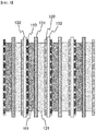
- FIG. 1 shows a cross-sectional structure of a manufactured secondary battery.
- FIG. 2 is a partially enlarged view of a cross-sectional structure in a horizontal direction of an electrode assembly included in a secondary battery
- FIG. 3 is a partial enlarged view of a cross-sectional structure in a vertical direction of an electrode assembly included in a secondary battery.
- a secondary battery 100 has a structure in which 50 unit cells are radially assembled around a central axis based on a horizontal cross-sectional structure.
- each unit cell has a structure in which the cell thickness decreases in the direction of the central axis from an outer end that forms an outer peripheral surface of the battery based on a horizontal cross-sectional structure.
- the unit cells constituting the secondary battery have a structure in which a negative electrode current collector 110, a negative electrode mixture layer 111, a first separator 131, a positive electrode mixture layer 121, a positive electrode current collector 120, and a second separator 132 are sequentially stacked.
- the negative electrode current collector 110 and the positive electrode current collector 120 have a structure in which through-type holes are formed in the thickness direction.
- the negative electrode mixture layer 111 and the positive electrode mixture layer 121 each have a structure in which the thickness of the mixture layers 111 and 121 applied on the metal current collectors 110 and 120 decrease and the density increases in the direction of the central axis from the outer end that forms the outer peripheral surface of the battery.
- a structure in which a negative electrode current collector 110, a negative electrode mixture layer 111, a first separator 131, a positive electrode mixture layer 121, a positive electrode current collector 120, and a second separator 132 are sequentially stacked, is repeated.
- the negative electrode current collector 110 and the positive electrode current collector 120 have a structure in which through-type holes are formed in the thickness direction. A plurality of through-type holes are formed in the negative electrode current collector 110 and the positive electrode current collector 120, and these through-type holes promote smooth flow of lithium ions.
- a secondary battery was manufactured in the same manner as in Example 1, except that a current collector having a mesh structure was used for each of the aluminum and copper current collectors.
- a positive electrode and a negative electrode were prepared in the same manner as in Example 1 except that through-thickness holes were not formed in the positive electrode and negative electrode current collectors respectively, and the thickness gradient of the positive electrode and negative electrode mixture layer was not formed.
- polypropylene was uniaxially stretched using a dry method to prepare a separator having a microporous structure having a melting point of 165°C and a width of 200 mm on one side.
- unit cells having a structure in which the first separator was interposed between the positive electrode and the negative electrode, and the second separator was located outside the positive electrode and the negative electrode were repeatedly assembled to prepare an electrode assembly.
- the electrode assembly has a structure in which 50 unit cells are sequentially assembled.
- Example 1 Physical properties were evaluated for each secondary battery prepared in Example 1 and Comparative Example 1. Specifically, charging and discharging were performed for each secondary battery, and voltage and temperature changes during charging and discharging were measured, respectively. Charging and discharging of the secondary battery was performed at 20°C and 1C.
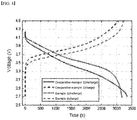
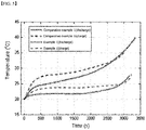
- FIG. 4 The result of evaluating the voltage change during charging and discharging of the secondary battery is shown in FIG. 4 , and the result of evaluating the temperature change during charging and discharging of the secondary battery is shown in FIG. 5 .
- the secondary battery according to Example 1 has a high discharge voltage and a low charging voltage compared to Comparative Example 1. Through this, it can be seen that the secondary battery according to Example 1 provides higher power when applied to a product, and requires lower charging power when charging.
- the secondary battery according to Example 1 has a lower temperature during charging and discharging and a remarkably small variation, compared to Comparative Example 1. Accordingly, the secondary battery according to the first embodiment has a lower required cooling performance, and a more compact design is possible. Therefore, the secondary battery can be applied to various mobile devices, wearable devices, etc., and it is particularly suitable for small devices such as wireless earphones and smart watches, especially devices requiring long-term use while being limited by the weight and volume of a secondary battery.
- the secondary battery since the secondary battery has excellent output, it can be used for power tools that are driven by a battery-based motor and it is suitable for application to electricity storage systems as well as drones, electric vehicles including electric vehicles (EVs), hybrid electric vehicles (HEVs), plug-in hybrid electric vehicles (PHEVs), etc., electric two-wheeled vehicles including electric bicycles (E-bikes) and electric scooters (E-scooters), and transportation means using high-power electricity, such as an electric golf carts.
- EVs electric vehicles
- HEVs hybrid electric vehicles
- PHEVs plug-in hybrid electric vehicles
- E-bikes electric bicycles
- E-scooters electric scooters
- transportation means using high-power electricity such as an electric golf carts.
Landscapes
- Chemical & Material Sciences (AREA)
- Chemical Kinetics & Catalysis (AREA)
- Electrochemistry (AREA)
- General Chemical & Material Sciences (AREA)
- Engineering & Computer Science (AREA)
- Manufacturing & Machinery (AREA)
- Materials Engineering (AREA)
- Aviation & Aerospace Engineering (AREA)
- Secondary Cells (AREA)
- Battery Electrode And Active Subsutance (AREA)
- Cell Electrode Carriers And Collectors (AREA)
Abstract
Description
- The present invention relates to a secondary battery including a structure in which unit cells whose thickness decreases in one direction are radially assembled, and a device including the same.
- This application claims the benefit of priority based on
Korean Patent Application No. 10-2019-0133561, filed on October 25, 2019 - As the price of energy sources increases due to the depletion of fossil fuels, and interest in environmental pollution is amplified, the demand for eco-friendly alternative energy sources is increasing. In particular, as technology development and demand for mobile devices increase, the demand for secondary batteries as energy sources is rapidly increasing. As the demand for secondary batteries is diversified and increased, there is a demand for new types of secondary batteries.
- In addition, in the case of a lithium secondary battery, lithium ions in an electrolyte solution generally exhibit high ion conductivity in a specific concentration range, and when the concentration is thinner or thicker than this, the ion conductivity decreases. The concentration of electrolyte solution or lithium ions inside the lithium secondary battery is not constant, and depending on the operating conditions of the battery, the concentrations of lithium ions near the positive electrode and the negative electrode behave in opposite directions.
- Therefore, there is a need for a new type of secondary battery technology that solves this problem.
- The present invention was invented to solve the above problems, and an object of the present invention is to provide a new type of secondary battery including a structure in which unit cells whose thickness decreases in one direction are radially assembled, and a device including the same.
- In one example, a secondary battery according to the present invention is formed as n (n is an integer of 5 or more) unit cells are radially assembled around a central axis based on a horizontal cross-sectional structure. Herein, each unit cell has a structure in which a thickness decreases in a direction toward the central axis from an outer end that forms an outer peripheral surface of the secondary battery based on the horizontal cross-sectional structure.
- In a specific example, in the secondary battery, a k-th (k is an integer between 1 and n-1) unit cell and a (k+1)-th unit cell are adjacent to each other and face each other. Further, a first unit cell and an n-th (n is an integer between 5 and 10000) unit cell are also adjacent to each other and face each other. The n value may vary depending on the size of the device to be applied. For mobile or small devices, n may be 1000 or less, and in the case of large cells for vehicles, etc., the unit cells may be aggregated in the range of 1000 to 10000.
- In one example, the secondary battery has a cylindrical structure in which n unit cells are radially assembled around the central axis to form a hollow based on the horizontal cross-sectional structure, wherein the n is an integer of 5 or more, and wherein a diameter ratio of inner and outer diameters of the secondary battery is in a range of 1 : 1.1 to 100.
- In yet another example, in each unit cell forming a battery, the ratio (Din : Dout) of the thickness (Din) of the inner end forming the inner peripheral surface of the battery in the center direction and the thickness (Dout) of the outer end forming the outer peripheral surface of the battery is in the range of 1 : 1.1 to 100, based on the horizontal cross-sectional structure.
- In a specific example, in each unit cell forming the battery, at least one of a positive electrode and a negative electrode has a structure in which a distance between electrodes decreases in a center direction from the outer end that forms an outer peripheral surface of the battery based on the horizontal cross-sectional structure.
- In another specific example, each unit cell comprises a positive electrode and a negative electrode, and each of the positive electrode and the negative electrode has a structure in which a mixture layer including an active material is applied on a metal current collector, and wherein at least one of the positive electrode or the negative electrode has a structure in which a thickness of the mixture layer applied on the metal current collector decreases in a direction toward the central axis from the outer end that forms the outer peripheral surface of the battery, based on the horizontal section structure.
- In another specific example, in each unit cell, at least one of the positive electrode or the negative electrode has a structure in which a density of the mixture layer increases in a direction toward the central axis from the outer end that forms the outer peripheral surface of the battery, based on the horizontal section structure.
- In one example, each unit cell includes a positive electrode and a negative electrode, and a first separator is interposed between the positive electrode and the negative electrode, and wherein a second separator is interposed between the unit cells.
- In a specific example, each of the positive electrode and the negative electrode includes: a current collector; and a mixture layer including an active material disposed on the current collector one a surface facing the first separator.
- In one example, in each unit cell, at least one of a positive electrode or a negative electrode includes a metal current collector having a porous structure in which through holes are formed in a thickness direction.
- In a specific example, in each unit cell forming the battery, a metal current collector forming at least one of a positive electrode and a negative electrode has a porous structure in which a through-thickness hole is formed, and an area ratio of the through holes on a surface of the metal current collector is in a range of 10 to 80%.
- For example, the metal current collector having the porous structure is in a form of a mesh.
- In further another example, the present invention provides a device including the above-described secondary battery. Specifically, the device may include a mobile device, a wearable device, a power tool that moves by receiving power by a battery-based motor, a drone, or an Electric Vehicle (EV), a Hybrid Electric Vehicle (HEV), a Plug-in Hybrid Electric Vehicle (PHEV), an Electric Bike (E-bike), an Electric Scooter (E-scooter), an Electric Golf Cart (electric golf cart) or a power storage system.
- A secondary battery and a device including the same according to the present invention propose a new structure in which unit cells whose thickness decreases in one direction are radially assembled, and when a current collector with a through-type hole formed in the thickness direction is applied, the variation in concentration of the electrolyte solution in the battery can be reduced, thereby improving battery performance.
-
-
FIG. 1 is a schematic diagram showing a cross-sectional structure of a secondary battery according to an embodiment of the present invention. -
FIGS. 2 and3 are partially enlarged views showing cross-sectional structures of an electrode assembly in a horizontal direction and a vertical direction, respectively, according to an embodiment of the present invention. -
FIGS. 4 and5 are graphs showing results of comparing and evaluating voltage and temperature changes during charging and discharging of a secondary battery according to an embodiment of the present invention, respectively. - Hereinafter, the present invention will be described in detail with reference to the drawings. The terms and words used in the present specification and claims should not be construed as limited to ordinary or dictionary terms and the inventor may properly define the concept of the terms in order to best describe its invention. The terms and words should be construed as meaning and concept consistent with the technical idea of the present invention.
- In addition, the meaning of "cylindrical" or "circular" in the present invention includes not only the case of a physical cylindrical or circular shape, but also a case in which the overall shape is close to a cylinder or a circle. For example, in the case that the cross-sectional shape of a battery is n-gonal shaped, if n is 5 or more, or 10 or more, it should be interpreted as being included in the circular category.
- In the present invention, based on a horizontal cross-sectional structure, n (n is an integer of 5 or more) unit cells are radially assembled around a central axis to form a battery. Herein, each unit cell provides a secondary battery having a structure in which a cell thickness decreases in a direction of a central axis from an outer end forming an outer peripheral surface of the battery based on a horizontal cross-sectional structure. In the secondary battery according to the present invention, a plurality of unit cells are radially assembled to form a battery. The shape of the secondary battery may have a circular shape or a shape close to it, an n-gonal shape, or a fan shape, based on a horizontal cross-sectional structure.
- The number n of unit cells collected in the secondary battery is an integer of 5 or more, and specifically in the range of 5 to 10000, 5 to 100, 100 to 1000, 1000 to 10000, 500 to 5000, or 3000 to 10000. The number n of the unit cells can be variously designed according to the shape, structure, or required physical properties of the battery.
- In one embodiment, in the secondary battery, the k-th (k is an integer between 1 and n-1) unit cell and the k+1-th unit cell are adjacent to each other and face each other. In addition, the first unit cell and the n-th unit cell (n is an integer between 5 and 10000) are also adjacent to each other and face each other. For example, in the secondary battery, a plurality of unit cells may be radially assembled to form a cylindrical structure. In this case, the outer peripheral surface of the cylindrical structure is determined by the number of unit cells, and a circular or n-gonal shape can be formed based on the cross section.
- In one embodiment, the secondary battery may have a structure in which a hollow penetrating in a vertical direction is formed in the center of the secondary battery as a whole and the exterior has a cylindrical shape. Specifically, the secondary battery has a cylindrical structure in which n unit cells (n is an integer of 5 or more) are radially aggregated around a central axis to form a hollow based on a horizontal cross-sectional structure. In addition, the secondary battery has a diameter ratio of an inner diameter and an outer diameter of 1 : 1.1 to 100. The diameter ratio of the inner diameter and the outer diameter of the secondary battery is calculated based on the average values of the inner diameters and the outer diameters, respectively. In a specific example, the secondary battery has a diameter ratio of the inner diameter and the outer diameter of the battery in the range of 1 : 1.1 to 100, 1 : 1.5 to 80, 1 : 2 to 50, 1 : 10 to 100, or 1 : 30 to 100.
- In yet another embodiment, in each unit cell forming a battery, the ratio (Din : Dout) of the thickness (Din) of the inner end forming the inner peripheral surface of the battery in the center direction and the thickness (Dout) of the outer end forming the outer peripheral surface of the battery is in the range of 1 : 1.5 to 10, based on the horizontal section structure. In a specific example, the ratio (Din : Dout) is in the range of 1 : 1.1 to 100, 1 : 1.5 to 80, 1 : 2 to 50, 1 : 10 to 100, or 1 : 30 to 100.
- The unit cell included in the secondary battery according to the present invention has a shape in which the thickness decreases in one direction. This is a form differentiated from conventional prismatic batteries, pouch-type batteries, or cylindrical batteries. Existing secondary batteries have a difference in external shape, but unit cells constituting each battery are manufactured with a uniform overall thickness, but are merely different in a stacked form or a winding form. In one embodiment, in each unit cell forming the battery, at least one of the positive electrode and the negative electrode has a structure in which the distance between the electrodes decreases in the center direction from the outer end that forms the outer peripheral surface of the battery based on the horizontal cross-sectional structure.
- In addition, by applying a structure in which the unit cells in the form in which the thickness decreases in one direction and the unit cells having a uniform thickness are assembled together, a secondary battery applicable to various types of devices can be manufactured. For example, in the case of a mobile smart watch, a secondary battery that can be stored inside the watch band may be applied. Herein, the watch band may be formed in a form in which a straight section area and a curved section area are combined. At this time, by using a secondary battery having a structure in which unit cells of uniform thickness are assembled in the straight section area of the watch band and unit cells whose thickness decreases in one direction are assembled in the curved section area, a secondary battery of a desired shape can be easily manufactured.
- In a specific embodiment, in each unit cell forming a battery, a positive electrode and a negative electrode each have a structure in which a mixture layer including an active material is applied on a metal current collector. Further, at least one of the positive electrode and the negative electrode has a structure in which the thickness of the mixture layer applied on the metal current collector decreases in the direction of the central axis at the outer end forming the outer peripheral surface of the battery based on the horizontal cross-sectional structure. That is, the present invention is designed to increase or decrease the thickness of the material mixture layer loaded on the current collector in one direction, thereby imparting thickness orientation to the unit cell.
- In another specific embodiment, in each unit cell forming a battery, a positive electrode and a negative electrode each have a structure in which a mixture layer including an active material is applied on a metal current collector. Further, at least one of the positive electrode and the negative electrode has a structure in which the density of the mixture layer applied on the metal current collector increases in the direction of the central axis from the outer end forming the outer peripheral surface of the battery based on the horizontal cross-sectional structure. As described above, when the present invention is designed to increase or decrease the thickness of the material mixture layer loaded in the current collector in one direction, capacity nonuniformity may occur depending on the location or direction of the unit cells. In the present invention, by designing to decrease or increase the density of the mixture layer loaded in the current collector in one direction, it is possible to compensate for the capacity unevenness according to the thickness orientation in the unit cell. For example, in an area in which the thickness of the mixture layer laminated on the current collector is small, the density of the mixture layer may be set to be high. The density orientation of the mixture layer can be realized by pressing or depressurizing in one direction when pressing with a roller while uniformly loading the mixture layer on the current collector.
- In one embodiment, each unit cell constituting the secondary battery according to the present invention includes a positive electrode and a negative electrode, a first separator is interposed between the positive electrode and the negative electrode, and a second separator is interposed between the unit cells. In this case, the positive electrode and the negative electrode may have a structure in which a mixture layer including an active material is laminated on one surface of a current collector in a direction facing the first separator.
- Specifically, in each unit cell forming a battery, a metal current collector forming at least one of a positive electrode and a negative electrode has a porous structure in which a through-thickness hole is formed. In the secondary battery according to the present invention, by applying a current collector having a through-type hole formed in the thickness direction to a unit cell, it is possible to improve the performance of the battery by reducing the width of change in the concentration of the electrolyte or lithium ions in the battery. In the present invention, by applying the current collector in which the through-type hole in the thickness direction is formed to the unit cell, the lithium ion concentration in the electrolyte solution can be uniformly maintained within a certain range. Through this, it is possible to increase battery performance by reducing an electrolyte-related overvoltage factor among overvoltage factors of a battery.
- In one embodiment, in each unit cell forming a battery, a metal current collector forming at least one of a positive electrode and a negative electrode has a porous structure in which a through-thickness hole is formed, and the area fraction in which the through-type hole is formed is in the range of 10 to 80%. Specifically, the area fraction in which the through hole is formed is in the range of 10 to 80%, 10 to 70%, 10 to 50%, 20 to 90%, 30 to 90%, or 30 to 60%. By controlling the number or area fraction per unit area of through holes in the above range, it is possible to reduce the deformation rate of the current collector and reduce the range of change of the electrolyte solution concentration and the lithium ion concentration in the battery without a significant decrease in mechanical strength.
- In a specific example, the through hole has a structure in which 10 to 500 holes are formed per unit area of 10 cm x 10 cm. Specifically, the number of through holes per unit area may be 10 to 300, 10 to 200, 10 to 100, 10 to 70, 30 to 50, 50 to 500, 100 to 200, 50 to 300, 100 to 500, 30 to 200, or 10 to 200. For example, the metal current collector has a mesh shape.
- The secondary battery in the present invention is, for example, a lithium secondary battery. The lithium secondary battery may include, for example, an electrode assembly described above; a non-aqueous electrolyte impregnating the electrode assembly; and a battery case containing the electrode assembly and the non-aqueous electrolyte.
- The positive electrode has a structure in which a positive electrode mixture layer is stacked on one or both sides of a positive electrode current collector. The positive electrode active materials may each independently be a lithium-containing oxide, and may be the same or different. A lithium-containing transition metal oxide may be used as the lithium-containing oxide. In one example, the positive electrode mixture layer includes a conductive material and a binder polymer in addition to the positive electrode active material, and if necessary, may further include a positive electrode additive commonly used in the art.
- The current collector used for the positive electrode is a metal having high conductivity, and any metal which the positive electrode active material slurry may be easily attached to and which is not reactive in the voltage range of the secondary battery can be used. Specifically, non-limiting examples of the current collector for the positive electrode include aluminum, nickel, or a foil manufactured by a combination thereof. Specifically, the current collector for the positive electrode is formed of metal components described above, and includes a metal plate having a through hole in the thickness direction, and an ion conductive porous reinforcing material filled in the through hole of the metal plate.
- The negative electrode may further include a negative electrode mixture layer, and may include a carbon material, lithium metal, silicon, or tin. When a carbon material is used as the negative electrode active material, both low crystalline carbon and high crystalline carbon may be used. Representative examples of low crystalline carbon include soft carbon and hard carbon are typical. Representative examples of high crystalline carbon include natural graphite, kish graphite, pyrolytic carbon, mesophase pitch based carbon fiber, mesocarbon microbeads, mesophase pitches, and high-temperature calcined carbons such as petroleum or coal tar pitch derived cokes.
- Non-limiting examples of the current collector used for the negative electrode include copper, gold, nickel, or a foil manufactured by a copper alloy or a combination thereof. In addition, the current collector may be used by stacking substrates made of the above materials. Specifically, the current collector for the negative electrode is formed of metal components described above, and includes a metal plate having a through hole in the thickness direction, and an ion conductive porous reinforcing material filled in the through hole of the metal plate.
- In addition, the negative electrode may include a conductive material and a binder commonly used in the art.
- The first and second separators may be made of any porous substrate used in a lithium secondary battery, and for example, a polyolefin-based porous membrane or a nonwoven fabric may be used, but the present invention is not particularly limited thereto. Examples of the polyolefin-based porous membrane include polyethylene such as high density polyethylene, linear low density polyethylene, low density polyethylene, ultra high molecular weight polyethylene, and a membrane in which polyolefin-based polymers, such as polypropylene, polybutylene, and polypentene, are each formed alone or in a mixture thereof.
- According to an embodiment of the present invention, the electrolyte may be a non-aqueous electrolyte. Examples of the solvent for the non-aqueous electrolyte include N-methyl-2-pyrrolidinone, propylene carbonate, ethylene carbonate, butylenecarbonate, dimethyl carbonate, diethyl carbonate, gamma-Butyrolactone, 1,2-dimethoxyethane, tetrahydroxyfuran, 2-methyltetrahydrofuran, dimethylsulfoxide, 1,3-dioxolane, formamide, dimethylformamide, dioxolane, acetonitrile, nitromethane, methyl formate, methyl acetate, phosphoric acid triester, trimethoxymethane, dioxolane derivatives, sulfolane, methyl sulfolane, 1,3-dimethyl-2-imidazolidinone, propylene carbonate derivatives, tetrahydrofuran derivatives, ethers, methyl pyrophosphate, ethyl propionate, etc. However, it is not particularly limited thereto, and a number of electrolyte components commonly used in the field of lithium secondary batteries may be added or subtracted within an appropriate range.
- In addition, the present invention provides a device including the secondary battery described above. In a specific example, the device includes a mobile device, a wearable device, a power tool that moves by receiving power by a battery-based motor, a drone, or an Electric Vehicle (EV), a Hybrid Electric Vehicle (HEV), a Plug-in Hybrid Electric Vehicle (PHEV), an Electric Bike (E-bike), an Electric Scooter (E-scooter), an Electric Golf Cart (electric golf cart) or a power storage system.
- For example, when the secondary battery of the present invention is included in a smart watch that is a mobile electronic device, conventional pouch-type batteries require stacking multiple thin electrodes on a flat surface, but the secondary batteries of the present invention can be manufactured in a hollow structure by itself, so that they are suitable to be manufactured according to the shape of a watch band. In addition, it can be applied to ultra-small devices such as wireless earphones because it can achieve high capacity compared to its size. On the other hand, since it is easy to adjust the size according to the number of unit cells assembled, it can be applied to large cylindrical batteries for electric vehicles.
- Hereinafter, the present invention will be described in more detail through examples and drawings. However, the embodiments described in the specification and the configurations described in the drawings are only the most preferred embodiments of the present invention, and do not represent all of the technical ideas of the present invention. It is to be understood that there may be various equivalents and variations in place of them at the time of filing the present application.
- 100 parts by weight of NCM (LiNi0.8Co0.1Mn0.1O2) as a positive electrode active material, 1.5 parts by weight of carbon black (FX35, Denka) as a conductive material, and 2.3 parts by weight of polyvinylidene fluoride (KF9700, Kureha) as a binder polymer were added to NMP (N-methyl-2-pyrrolidone) as a solvent to thereby prepare a positive electrode mixture layer slurry. The positive electrode mixture layer slurry was coated on one side of an aluminum current collector with through holes in a thickness direction in a loading amount of 640 mg/25 cm2 and then vacuum-dried to thereby obtain a positive electrode. In the aluminum current collector, the through-type holes are formed in an area fraction of about 40%, and about 50 holes are formed per unit area of 10 cm x 10 cm. In addition, the positive electrode mixture layer was pressed to decrease sequentially to a thickness of about 40% in one direction.
- 100 parts by weight of artificial graphite (GT, Zichen (China)) as a negative electrode active material, 1.1 parts by weight of carbon black (Super-P) as a conductive material, 2.2 parts by weight of styrene-butadiene rubber, and 0.7 parts by weight of carboxy methyl cellulose were added to water as a solvent to prepare a negative electrode material slurry, and was then coated, dried and pressed on one side of a copper current collector with through holes in a thickness direction, to thereby manufacture a negative electrode. In the copper current collector, the through-type holes are formed in an area fraction of about 40%, and about 50 holes are formed per unit area of 10 cm x 10 cm. In addition, the negative electrode mixture layer was pressed to decrease sequentially to a thickness of about 40% in one direction.
- On the other hand, polypropylene was uniaxially stretched using a dry method to prepare a separator having a microporous structure having a melting point of 165°C and a width of 200 mm on one side. unit cells having a structure in which the first separator was interposed between the positive electrode and the negative electrode, and the second separator was located outside the positive electrode and the negative electrode were repeatedly assembled to prepare an electrode assembly. The electrode assembly has a structure in which 50 unit cells are radially assembled around a central axis based on a horizontal cross-sectional structure.
- After the electrode assembly was built into a hollow cylindrical battery case, a 1M LiPF6 carbonate-based solution electrolyte was injected to complete a battery.
-
FIG. 1 shows a cross-sectional structure of a manufactured secondary battery. In addition,FIG. 2 is a partially enlarged view of a cross-sectional structure in a horizontal direction of an electrode assembly included in a secondary battery, andFIG. 3 is a partial enlarged view of a cross-sectional structure in a vertical direction of an electrode assembly included in a secondary battery. - Referring to
FIG. 1 , asecondary battery 100 according to an embodiment of the present invention has a structure in which 50 unit cells are radially assembled around a central axis based on a horizontal cross-sectional structure. In addition, each unit cell has a structure in which the cell thickness decreases in the direction of the central axis from an outer end that forms an outer peripheral surface of the battery based on a horizontal cross-sectional structure. - Referring to
FIG. 2 , the unit cells constituting the secondary battery have a structure in which a negative electrodecurrent collector 110, a negativeelectrode mixture layer 111, afirst separator 131, a positiveelectrode mixture layer 121, a positive electrodecurrent collector 120, and asecond separator 132 are sequentially stacked. In addition, the negative electrodecurrent collector 110 and the positive electrodecurrent collector 120 have a structure in which through-type holes are formed in the thickness direction. The negativeelectrode mixture layer 111 and the positiveelectrode mixture layer 121 each have a structure in which the thickness of the mixture layers 111 and 121 applied on the metalcurrent collectors - Referring to
FIG. 3 , in the unit cells constituting the secondary battery, a structure, in which a negative electrodecurrent collector 110, a negativeelectrode mixture layer 111, afirst separator 131, a positiveelectrode mixture layer 121, a positive electrodecurrent collector 120, and asecond separator 132 are sequentially stacked, is repeated. In addition, the negative electrodecurrent collector 110 and the positive electrodecurrent collector 120 have a structure in which through-type holes are formed in the thickness direction. A plurality of through-type holes are formed in the negative electrodecurrent collector 110 and the positive electrodecurrent collector 120, and these through-type holes promote smooth flow of lithium ions. - A secondary battery was manufactured in the same manner as in Example 1, except that a current collector having a mesh structure was used for each of the aluminum and copper current collectors.
- A positive electrode and a negative electrode were prepared in the same manner as in Example 1 except that through-thickness holes were not formed in the positive electrode and negative electrode current collectors respectively, and the thickness gradient of the positive electrode and negative electrode mixture layer was not formed.
- On the other hand, polypropylene was uniaxially stretched using a dry method to prepare a separator having a microporous structure having a melting point of 165°C and a width of 200 mm on one side. unit cells having a structure in which the first separator was interposed between the positive electrode and the negative electrode, and the second separator was located outside the positive electrode and the negative electrode were repeatedly assembled to prepare an electrode assembly. The electrode assembly has a structure in which 50 unit cells are sequentially assembled.
- After the electrode assembly was built into a hollow rectangular battery case, a 1M LiPF6 carbonate-based solution electrolyte was injected to complete a battery.
- Physical properties were evaluated for each secondary battery prepared in Example 1 and Comparative Example 1. Specifically, charging and discharging were performed for each secondary battery, and voltage and temperature changes during charging and discharging were measured, respectively. Charging and discharging of the secondary battery was performed at 20°C and 1C.
- The result of evaluating the voltage change during charging and discharging of the secondary battery is shown in
FIG. 4 , and the result of evaluating the temperature change during charging and discharging of the secondary battery is shown inFIG. 5 . - First, referring to
FIG. 4 , it can be seen that the secondary battery according to Example 1 has a high discharge voltage and a low charging voltage compared to Comparative Example 1. Through this, it can be seen that the secondary battery according to Example 1 provides higher power when applied to a product, and requires lower charging power when charging. - Referring to
FIG. 5 , it can be seen that the secondary battery according to Example 1 has a lower temperature during charging and discharging and a remarkably small variation, compared to Comparative Example 1. Accordingly, the secondary battery according to the first embodiment has a lower required cooling performance, and a more compact design is possible. Therefore, the secondary battery can be applied to various mobile devices, wearable devices, etc., and it is particularly suitable for small devices such as wireless earphones and smart watches, especially devices requiring long-term use while being limited by the weight and volume of a secondary battery. - In addition, since the secondary battery has excellent output, it can be used for power tools that are driven by a battery-based motor and it is suitable for application to electricity storage systems as well as drones, electric vehicles including electric vehicles (EVs), hybrid electric vehicles (HEVs), plug-in hybrid electric vehicles (PHEVs), etc., electric two-wheeled vehicles including electric bicycles (E-bikes) and electric scooters (E-scooters), and transportation means using high-power electricity, such as an electric golf carts.
-
- 100:
- secondary battery
- 110:
- negative electrode current collector
- 111:
- negative electrode mixture layer
- 120:
- positive electrode current collector
- 121:
- positive electrode mixture layer
- 131:
- first separator
- 132:
- second separator
Claims (14)
- A secondary battery having a structure in which n unit cells are radially assembled around a central axis based on a horizontal cross-sectional structure,wherein n is an integer of 5 or more, andwherein each unit cell has a structure in which a thickness decreases in a direction toward the central axis from an outer end that forms an outer peripheral surface of the secondary battery based on the horizontal cross-sectional structure.
- The secondary battery of claim 1, wherein a kth unit cell and a (k+1)th unit cell are adjacent to each other and face each other,wherein the k is an integer between 1 and n-1,wherein a first unit cell and an nth unit cell are also adjacent to each other and face each other, andwherein the n is an integer between 5 and 10000.
- The secondary battery of claim 1, wherein the secondary battery has a cylindrical structure in which n unit cells are radially assembled around the central axis to form a hollow based on the horizontal cross-sectional structure,wherein the n is an integer of 5 or more, andwherein a diameter ratio of inner and outer diameters of the secondary battery is in a range of 1 : 1.1 to 100.
- The secondary battery of claim 1, wherein, in each unit cell forming a battery, the ratio (Din : Dout) of the thickness (Din) of the inner end forming the inner peripheral surface of the battery in the center direction and the thickness (Dout) of the outer end forming the outer peripheral surface of the battery is in the range of 1 : 1.1 to 100, based on the horizontal cross-sectional structure.
- The secondary battery of claim 1, wherein, in each unit cell forming the battery, at least one of a positive electrode and a negative electrode has a structure in which a distance between electrodes decreases in a center direction from the outer end that forms an outer peripheral surface of the battery based on the horizontal cross-sectional structure.
- The secondary battery of claim 1, wherein each unit cell comprises a positive electrode and a negative electrode, and each of the positive electrode and the negative electrode has a structure in which a mixture layer including an active material is applied on a metal current collector, and
wherein at least one of the positive electrode or the negative electrode has a structure in which a thickness of the mixture layer applied on the metal current collector decreases in a direction toward the central axis from the outer end that forms the outer peripheral surface of the battery, based on the horizontal section structure. - The secondary battery of claim 6, wherein, in each unit cell, at least one of the positive electrode or the negative electrode has a structure in which a density of the mixture layer increases in a direction toward the central axis from the outer end that forms the outer peripheral surface of the battery, based on the horizontal section structure.
- The secondary battery of claim 1, wherein each unit cell includes a positive electrode and a negative electrode, and a first separator is interposed between the positive electrode and the negative electrode, and
wherein a second separator is interposed between the unit cells. - The secondary battery of claim 8, wherein each of the positive electrode and the negative electrode includes: a current collector; and a mixture layer including an active material disposed on the current collector one a surface facing the first separator.
- The secondary battery of claim 1, wherein, in each unit cell, at least one of a positive electrode or a negative electrode includes a metal current collector having a porous structure in which through holes are formed in a thickness direction.
- The secondary battery of claim 10, wherein, in each unit cell,
an area ratio of the through holes on a surface of the metal current colletor is in a range of 10 to 80%. - The secondary battery of claim 10, wherein the metal current collector is in a form of a mesh.
- A device comprising the secondary battery according to claim 1.
- The device of claim 13, wherein the device includes a mobile device, a wearable device, a power tool that moves by receiving power by a battery-based motor, a drone, or an Electric Vehicle (EV), a Hybrid Electric Vehicle (HEV), a Plug-in Hybrid Electric Vehicle (PHEV), an Electric Bike (E-bike), an Electric Scooter (E-scooter), an Electric Golf Cart (electric golf cart) or a power storage system.
Applications Claiming Priority (2)
| Application Number | Priority Date | Filing Date | Title |
|---|---|---|---|
| KR1020190133561A KR102900627B1 (en) | 2019-10-25 | 2019-10-25 | Secondary Battery Comprising Unit Cell Assembly Having Radial Structure |
| PCT/KR2020/010615 WO2021080137A1 (en) | 2019-10-25 | 2020-08-11 | Secondary battery having structure in which unit cells which become thinner in one direction are radially assembled, and device comprising same |
Publications (3)
| Publication Number | Publication Date |
|---|---|
| EP3916865A1 true EP3916865A1 (en) | 2021-12-01 |
| EP3916865A4 EP3916865A4 (en) | 2022-06-01 |
| EP3916865B1 EP3916865B1 (en) | 2025-10-29 |
Family
ID=75619327
Family Applications (1)
| Application Number | Title | Priority Date | Filing Date |
|---|---|---|---|
| EP20878093.2A Active EP3916865B1 (en) | 2019-10-25 | 2020-08-11 | Secondary battery having structure in which unit cells which become thinner in one direction are radially assembled, and device comprising same |
Country Status (8)
| Country | Link |
|---|---|
| US (1) | US20220140382A1 (en) |
| EP (1) | EP3916865B1 (en) |
| JP (1) | JP7293382B2 (en) |
| KR (1) | KR102900627B1 (en) |
| CN (1) | CN113728501A (en) |
| ES (1) | ES3054101T3 (en) |
| PL (1) | PL3916865T3 (en) |
| WO (1) | WO2021080137A1 (en) |
Families Citing this family (1)
| Publication number | Priority date | Publication date | Assignee | Title |
|---|---|---|---|---|
| WO2026075179A1 (en) * | 2024-10-03 | 2026-04-09 | マクセル株式会社 | Electrode layered body, method for manufacturing same, and electrochemical element |
Family Cites Families (19)
| Publication number | Priority date | Publication date | Assignee | Title |
|---|---|---|---|---|
| JPS50134631U (en) * | 1974-04-19 | 1975-11-06 | ||
| JPS5165331A (en) * | 1974-11-30 | 1976-06-05 | Shin Kobe Electric Machinery | |
| JPS5629891Y2 (en) * | 1975-01-20 | 1981-07-16 | ||
| JPH07130344A (en) * | 1993-10-29 | 1995-05-19 | Sanyo Electric Co Ltd | Collective battery |
| KR100329560B1 (en) * | 1999-04-16 | 2002-03-20 | 김순택 | Grid, electrode and secondary battery utilizing the sames |
| JP2003208917A (en) * | 2002-01-10 | 2003-07-25 | Nissan Motor Co Ltd | Fuel cell system |
| US7291422B2 (en) * | 2003-10-10 | 2007-11-06 | Nissan Motor Co., Ltd. | Battery and related method |
| KR20060015060A (en) * | 2004-08-13 | 2006-02-16 | 삼성에스디아이 주식회사 | Electrode plate for secondary battery |
| KR100805108B1 (en) * | 2006-04-25 | 2008-02-21 | 삼성에스디아이 주식회사 | Battery module |
| JP5347428B2 (en) * | 2008-10-23 | 2013-11-20 | マツダ株式会社 | Secondary battery |
| US20120288747A1 (en) * | 2010-01-29 | 2012-11-15 | Jsr Corporation | Electrochemical device |
| CN103563133B (en) * | 2011-05-31 | 2016-08-17 | 日本瑞翁株式会社 | Composite particle for positive electrode of lithium secondary battery, method for producing composite particle for positive electrode for lithium secondary battery, method for producing positive electrode for lithium secondary battery, positive electrode for lithium secondary battery, and lithium secondary battery |
| JP2014007108A (en) * | 2012-06-26 | 2014-01-16 | Mitsubishi Motors Corp | Secondary battery |
| KR101621591B1 (en) * | 2013-01-03 | 2016-05-16 | 주식회사 엘지화학 | asymmetric electrode plate, asymmetric electrode assembly having asymmetric electrode plate, and asymmetric secondary battery having asymmetric electrode assembly |
| CN105186006B (en) * | 2014-06-17 | 2017-08-11 | 北京好风光储能技术有限公司 | A kind of compound porous collector and preparation method and application |
| KR102026292B1 (en) * | 2015-08-20 | 2019-11-26 | 주식회사 엘지화학 | Electrode Assembly Comprising Electrode Having Gradient in Loading Amount of Active Material |
| KR101859872B1 (en) | 2017-04-28 | 2018-05-18 | 주식회사 엘지화학 | Electrode assembly and Method of forming electrode assemly, Secondary battery and Method of forming secondary battery |
| KR102149973B1 (en) | 2018-05-23 | 2020-08-31 | (주)에스디생명공학 | Antimicrobial and Antifungal Composition Comprising Eugenol and Gallic Acid as Active Ingredient |
| CN109830690A (en) * | 2019-01-30 | 2019-05-31 | 深圳鸿鹏新能源科技有限公司 | Collector and pole piece and lithium battery with the collector |
-
2019
- 2019-10-25 KR KR1020190133561A patent/KR102900627B1/en active Active
-
2020
- 2020-08-11 CN CN202080030235.9A patent/CN113728501A/en active Pending
- 2020-08-11 US US17/435,353 patent/US20220140382A1/en active Pending
- 2020-08-11 ES ES20878093T patent/ES3054101T3/en active Active
- 2020-08-11 WO PCT/KR2020/010615 patent/WO2021080137A1/en not_active Ceased
- 2020-08-11 EP EP20878093.2A patent/EP3916865B1/en active Active
- 2020-08-11 JP JP2021552662A patent/JP7293382B2/en active Active
- 2020-08-11 PL PL20878093.2T patent/PL3916865T3/en unknown
Also Published As
| Publication number | Publication date |
|---|---|
| EP3916865B1 (en) | 2025-10-29 |
| KR102900627B1 (en) | 2025-12-15 |
| JP2022523556A (en) | 2022-04-25 |
| JP7293382B2 (en) | 2023-06-19 |
| KR20210049353A (en) | 2021-05-06 |
| CN113728501A (en) | 2021-11-30 |
| PL3916865T3 (en) | 2026-01-26 |
| EP3916865A4 (en) | 2022-06-01 |
| ES3054101T3 (en) | 2026-01-29 |
| WO2021080137A1 (en) | 2021-04-29 |
| US20220140382A1 (en) | 2022-05-05 |
Similar Documents
| Publication | Publication Date | Title |
|---|---|---|
| US11777080B2 (en) | Negative electrode for secondary battery | |
| US10326136B2 (en) | Porous carbonized composite material for high-performing silicon anodes | |
| US10637097B2 (en) | Organic/inorganic composite electrolyte, electrode-electrolyte assembly and lithium secondary battery including the same, and manufacturing method of the electrode-electrolyte assembly | |
| JP5150966B2 (en) | Non-aqueous electrolyte secondary battery positive electrode and non-aqueous electrolyte secondary battery using the same | |
| KR101543939B1 (en) | Nonaqueous electrolytic-solution rechargeable battery | |
| EP3358653B1 (en) | Negative electrode for lithium ion secondary batteries and lithium ion secondary battery | |
| EP2819219A1 (en) | Bipolar electrode and bipolar lithium-ion secondary battery using same | |
| CN112714971B (en) | Negative electrode active material for lithium secondary battery, negative electrode comprising same, and lithium secondary battery | |
| CN101809790A (en) | Electrode body, and lithium secondary battery employing the electrode body | |
| KR102909741B1 (en) | Method for charging and discharging secondary battery | |
| EP4113680B1 (en) | Electrode assembly and secondary battery including the same | |
| KR20190044536A (en) | Positive electrode active material for lithium secondary battery, preparing method of the same, positive electrode and lithium secondary battery including the same | |
| KR20220037675A (en) | Negative electrode and secondary battery comprising the same | |
| KR102766500B1 (en) | Battery system, method for using the same, and battery pack comprising the same | |
| US20220093923A1 (en) | Method for preparing negative electrode active material | |
| CN214313261U (en) | Current collector and secondary battery, battery module and device including the same | |
| EP3916865B1 (en) | Secondary battery having structure in which unit cells which become thinner in one direction are radially assembled, and device comprising same | |
| KR102273781B1 (en) | Negative active material and preparation method thereof | |
| EP4528845A1 (en) | Negative electrode and secondary battery | |
| KR20210024975A (en) | Lithium secondary battery and method for manufacturing the same | |
| KR101587921B1 (en) | Anode For Cable type Secondary Battery, A Manufacturing Method of The Same And Cable type Secondary Battery Having The Same | |
| KR102940170B1 (en) | High-charge and high-stability lithium secondary battery manufacturing process through magnetic field application | |
| EP4539136A1 (en) | Negative electrode and secondary battery | |
| CN113192760B (en) | Hybrid supercapacitor and device employing the same | |
| KR102328262B1 (en) | Sulfur-carbon composite, positive electrode and lithium secondary battery comprising the same |
Legal Events
| Date | Code | Title | Description |
|---|---|---|---|
| STAA | Information on the status of an ep patent application or granted ep patent |
Free format text: STATUS: THE INTERNATIONAL PUBLICATION HAS BEEN MADE |
|
| PUAI | Public reference made under article 153(3) epc to a published international application that has entered the european phase |
Free format text: ORIGINAL CODE: 0009012 |
|
| STAA | Information on the status of an ep patent application or granted ep patent |
Free format text: STATUS: REQUEST FOR EXAMINATION WAS MADE |
|
| 17P | Request for examination filed |
Effective date: 20210823 |
|
| AK | Designated contracting states |
Kind code of ref document: A1 Designated state(s): AL AT BE BG CH CY CZ DE DK EE ES FI FR GB GR HR HU IE IS IT LI LT LU LV MC MK MT NL NO PL PT RO RS SE SI SK SM TR |
|
| RAP3 | Party data changed (applicant data changed or rights of an application transferred) |
Owner name: LG ENERGY SOLUTION, LTD. |
|
| A4 | Supplementary search report drawn up and despatched |
Effective date: 20220503 |
|
| RIC1 | Information provided on ipc code assigned before grant |
Ipc: H01M 50/207 20210101ALI20220427BHEP Ipc: H01M 4/02 20060101ALI20220427BHEP Ipc: H01M 4/66 20060101ALI20220427BHEP Ipc: H01M 4/80 20060101ALI20220427BHEP Ipc: H01M 4/74 20060101ALI20220427BHEP Ipc: H01M 10/04 20060101AFI20220427BHEP |
|
| DAV | Request for validation of the european patent (deleted) | ||
| DAX | Request for extension of the european patent (deleted) | ||
| STAA | Information on the status of an ep patent application or granted ep patent |
Free format text: STATUS: EXAMINATION IS IN PROGRESS |
|
| 17Q | First examination report despatched |
Effective date: 20240709 |
|
| REG | Reference to a national code |
Ref legal event code: R079 Ref country code: DE Ref legal event code: R079 Ref document number: 602020061422 Country of ref document: DE Free format text: PREVIOUS MAIN CLASS: H01M0010040000 Ipc: H01M0050207000 |
|
| GRAP | Despatch of communication of intention to grant a patent |
Free format text: ORIGINAL CODE: EPIDOSNIGR1 |
|
| STAA | Information on the status of an ep patent application or granted ep patent |
Free format text: STATUS: GRANT OF PATENT IS INTENDED |
|
| RIC1 | Information provided on ipc code assigned before grant |
Ipc: H01M 50/207 20210101AFI20250707BHEP Ipc: H01M 10/04 20060101ALI20250707BHEP Ipc: H01M 4/80 20060101ALI20250707BHEP Ipc: H01M 4/74 20060101ALI20250707BHEP Ipc: H01M 4/02 20060101ALN20250707BHEP |
|
| INTG | Intention to grant announced |
Effective date: 20250721 |
|
| GRAS | Grant fee paid |
Free format text: ORIGINAL CODE: EPIDOSNIGR3 |
|
| GRAA | (expected) grant |
Free format text: ORIGINAL CODE: 0009210 |
|
| STAA | Information on the status of an ep patent application or granted ep patent |
Free format text: STATUS: THE PATENT HAS BEEN GRANTED |
|
| P01 | Opt-out of the competence of the unified patent court (upc) registered |
Free format text: CASE NUMBER: UPC_APP_4870_3916865/2025 Effective date: 20250827 |
|
| AK | Designated contracting states |
Kind code of ref document: B1 Designated state(s): AL AT BE BG CH CY CZ DE DK EE ES FI FR GB GR HR HU IE IS IT LI LT LU LV MC MK MT NL NO PL PT RO RS SE SI SK SM TR |
|
| REG | Reference to a national code |
Ref country code: CH Ref legal event code: F10 Free format text: ST27 STATUS EVENT CODE: U-0-0-F10-F00 (AS PROVIDED BY THE NATIONAL OFFICE) Effective date: 20251029 Ref country code: GB Ref legal event code: FG4D |
|
| REG | Reference to a national code |
Ref country code: DE Ref legal event code: R096 Ref document number: 602020061422 Country of ref document: DE |
|
| REG | Reference to a national code |
Ref country code: IE Ref legal event code: FG4D |
|
| REG | Reference to a national code |
Ref country code: SE Ref legal event code: TRGR |
|
| REG | Reference to a national code |
Ref country code: ES Ref legal event code: FG2A Ref document number: 3054101 Country of ref document: ES Kind code of ref document: T3 Effective date: 20260129 |
|
| REG | Reference to a national code |
Ref country code: NL Ref legal event code: MP Effective date: 20251029 |
|
| REG | Reference to a national code |
Ref country code: LT Ref legal event code: MG9D |
|
| PG25 | Lapsed in a contracting state [announced via postgrant information from national office to epo] |
Ref country code: NO Free format text: LAPSE BECAUSE OF FAILURE TO SUBMIT A TRANSLATION OF THE DESCRIPTION OR TO PAY THE FEE WITHIN THE PRESCRIBED TIME-LIMIT Effective date: 20260129 |
|
| PG25 | Lapsed in a contracting state [announced via postgrant information from national office to epo] |
Ref country code: AT Free format text: LAPSE BECAUSE OF FAILURE TO SUBMIT A TRANSLATION OF THE DESCRIPTION OR TO PAY THE FEE WITHIN THE PRESCRIBED TIME-LIMIT Effective date: 20251029 Ref country code: FI Free format text: LAPSE BECAUSE OF FAILURE TO SUBMIT A TRANSLATION OF THE DESCRIPTION OR TO PAY THE FEE WITHIN THE PRESCRIBED TIME-LIMIT Effective date: 20251029 Ref country code: HR Free format text: LAPSE BECAUSE OF FAILURE TO SUBMIT A TRANSLATION OF THE DESCRIPTION OR TO PAY THE FEE WITHIN THE PRESCRIBED TIME-LIMIT Effective date: 20251029 |
|
| REG | Reference to a national code |
Ref country code: AT Ref legal event code: MK05 Ref document number: 1852727 Country of ref document: AT Kind code of ref document: T Effective date: 20251029 |
|
| PG25 | Lapsed in a contracting state [announced via postgrant information from national office to epo] |
Ref country code: NL Free format text: LAPSE BECAUSE OF FAILURE TO SUBMIT A TRANSLATION OF THE DESCRIPTION OR TO PAY THE FEE WITHIN THE PRESCRIBED TIME-LIMIT Effective date: 20251029 |
|
| PG25 | Lapsed in a contracting state [announced via postgrant information from national office to epo] |
Ref country code: RS Free format text: LAPSE BECAUSE OF FAILURE TO SUBMIT A TRANSLATION OF THE DESCRIPTION OR TO PAY THE FEE WITHIN THE PRESCRIBED TIME-LIMIT Effective date: 20260129 |
|
| PG25 | Lapsed in a contracting state [announced via postgrant information from national office to epo] |
Ref country code: IS Free format text: LAPSE BECAUSE OF FAILURE TO SUBMIT A TRANSLATION OF THE DESCRIPTION OR TO PAY THE FEE WITHIN THE PRESCRIBED TIME-LIMIT Effective date: 20260228 |
|
| PG25 | Lapsed in a contracting state [announced via postgrant information from national office to epo] |
Ref country code: PT Free format text: LAPSE BECAUSE OF FAILURE TO SUBMIT A TRANSLATION OF THE DESCRIPTION OR TO PAY THE FEE WITHIN THE PRESCRIBED TIME-LIMIT Effective date: 20260302 |
|
| PG25 | Lapsed in a contracting state [announced via postgrant information from national office to epo] |
Ref country code: LV Free format text: LAPSE BECAUSE OF FAILURE TO SUBMIT A TRANSLATION OF THE DESCRIPTION OR TO PAY THE FEE WITHIN THE PRESCRIBED TIME-LIMIT Effective date: 20251029 |