EP3916863A1 - Sealing gasket and cylindrical battery - Google Patents
Sealing gasket and cylindrical battery Download PDFInfo
- Publication number
- EP3916863A1 EP3916863A1 EP19912042.9A EP19912042A EP3916863A1 EP 3916863 A1 EP3916863 A1 EP 3916863A1 EP 19912042 A EP19912042 A EP 19912042A EP 3916863 A1 EP3916863 A1 EP 3916863A1
- Authority
- EP
- European Patent Office
- Prior art keywords
- sealing gasket
- battery
- partition portion
- open end
- stress buffer
- Prior art date
- Legal status (The legal status is an assumption and is not a legal conclusion. Google has not performed a legal analysis and makes no representation as to the accuracy of the status listed.)
- Pending
Links
Images


Classifications
-
- H—ELECTRICITY
- H01—ELECTRIC ELEMENTS
- H01M—PROCESSES OR MEANS, e.g. BATTERIES, FOR THE DIRECT CONVERSION OF CHEMICAL ENERGY INTO ELECTRICAL ENERGY
- H01M50/00—Constructional details or processes of manufacture of the non-active parts of electrochemical cells other than fuel cells, e.g. hybrid cells
- H01M50/10—Primary casings; Jackets or wrappings
- H01M50/147—Lids or covers
- H01M50/148—Lids or covers characterised by their shape
- H01M50/154—Lid or cover comprising an axial bore for receiving a central current collector
-
- H—ELECTRICITY
- H01—ELECTRIC ELEMENTS
- H01M—PROCESSES OR MEANS, e.g. BATTERIES, FOR THE DIRECT CONVERSION OF CHEMICAL ENERGY INTO ELECTRICAL ENERGY
- H01M6/00—Primary cells; Manufacture thereof
- H01M6/02—Details
-
- H—ELECTRICITY
- H01—ELECTRIC ELEMENTS
- H01M—PROCESSES OR MEANS, e.g. BATTERIES, FOR THE DIRECT CONVERSION OF CHEMICAL ENERGY INTO ELECTRICAL ENERGY
- H01M50/00—Constructional details or processes of manufacture of the non-active parts of electrochemical cells other than fuel cells, e.g. hybrid cells
- H01M50/10—Primary casings; Jackets or wrappings
- H01M50/147—Lids or covers
- H01M50/166—Lids or covers characterised by the methods of assembling casings with lids
- H01M50/171—Lids or covers characterised by the methods of assembling casings with lids using adhesives or sealing agents
-
- H—ELECTRICITY
- H01—ELECTRIC ELEMENTS
- H01M—PROCESSES OR MEANS, e.g. BATTERIES, FOR THE DIRECT CONVERSION OF CHEMICAL ENERGY INTO ELECTRICAL ENERGY
- H01M50/00—Constructional details or processes of manufacture of the non-active parts of electrochemical cells other than fuel cells, e.g. hybrid cells
- H01M50/10—Primary casings; Jackets or wrappings
- H01M50/102—Primary casings; Jackets or wrappings characterised by their shape or physical structure
- H01M50/107—Primary casings; Jackets or wrappings characterised by their shape or physical structure having curved cross-section, e.g. round or elliptic
-
- H—ELECTRICITY
- H01—ELECTRIC ELEMENTS
- H01M—PROCESSES OR MEANS, e.g. BATTERIES, FOR THE DIRECT CONVERSION OF CHEMICAL ENERGY INTO ELECTRICAL ENERGY
- H01M50/00—Constructional details or processes of manufacture of the non-active parts of electrochemical cells other than fuel cells, e.g. hybrid cells
- H01M50/10—Primary casings; Jackets or wrappings
- H01M50/147—Lids or covers
- H01M50/148—Lids or covers characterised by their shape
- H01M50/152—Lids or covers characterised by their shape for cells having curved cross-section, e.g. round or elliptic
-
- H—ELECTRICITY
- H01—ELECTRIC ELEMENTS
- H01M—PROCESSES OR MEANS, e.g. BATTERIES, FOR THE DIRECT CONVERSION OF CHEMICAL ENERGY INTO ELECTRICAL ENERGY
- H01M50/00—Constructional details or processes of manufacture of the non-active parts of electrochemical cells other than fuel cells, e.g. hybrid cells
- H01M50/10—Primary casings; Jackets or wrappings
- H01M50/147—Lids or covers
- H01M50/166—Lids or covers characterised by the methods of assembling casings with lids
- H01M50/167—Lids or covers characterised by the methods of assembling casings with lids by crimping
-
- H—ELECTRICITY
- H01—ELECTRIC ELEMENTS
- H01M—PROCESSES OR MEANS, e.g. BATTERIES, FOR THE DIRECT CONVERSION OF CHEMICAL ENERGY INTO ELECTRICAL ENERGY
- H01M50/00—Constructional details or processes of manufacture of the non-active parts of electrochemical cells other than fuel cells, e.g. hybrid cells
- H01M50/10—Primary casings; Jackets or wrappings
- H01M50/183—Sealing members
- H01M50/184—Sealing members characterised by their shape or structure
-
- H—ELECTRICITY
- H01—ELECTRIC ELEMENTS
- H01M—PROCESSES OR MEANS, e.g. BATTERIES, FOR THE DIRECT CONVERSION OF CHEMICAL ENERGY INTO ELECTRICAL ENERGY
- H01M50/00—Constructional details or processes of manufacture of the non-active parts of electrochemical cells other than fuel cells, e.g. hybrid cells
- H01M50/10—Primary casings; Jackets or wrappings
- H01M50/183—Sealing members
- H01M50/186—Sealing members characterised by the disposition of the sealing members
-
- H—ELECTRICITY
- H01—ELECTRIC ELEMENTS
- H01M—PROCESSES OR MEANS, e.g. BATTERIES, FOR THE DIRECT CONVERSION OF CHEMICAL ENERGY INTO ELECTRICAL ENERGY
- H01M50/00—Constructional details or processes of manufacture of the non-active parts of electrochemical cells other than fuel cells, e.g. hybrid cells
- H01M50/10—Primary casings; Jackets or wrappings
- H01M50/183—Sealing members
- H01M50/19—Sealing members characterised by the material
- H01M50/193—Organic material
-
- H—ELECTRICITY
- H01—ELECTRIC ELEMENTS
- H01M—PROCESSES OR MEANS, e.g. BATTERIES, FOR THE DIRECT CONVERSION OF CHEMICAL ENERGY INTO ELECTRICAL ENERGY
- H01M50/00—Constructional details or processes of manufacture of the non-active parts of electrochemical cells other than fuel cells, e.g. hybrid cells
- H01M50/10—Primary casings; Jackets or wrappings
- H01M50/183—Sealing members
- H01M50/19—Sealing members characterised by the material
- H01M50/198—Sealing members characterised by the material characterised by physical properties, e.g. adhesiveness or hardness
-
- H—ELECTRICITY
- H01—ELECTRIC ELEMENTS
- H01M—PROCESSES OR MEANS, e.g. BATTERIES, FOR THE DIRECT CONVERSION OF CHEMICAL ENERGY INTO ELECTRICAL ENERGY
- H01M6/00—Primary cells; Manufacture thereof
- H01M6/04—Cells with aqueous electrolyte
- H01M6/06—Dry cells, i.e. cells wherein the electrolyte is rendered non-fluid
- H01M6/08—Dry cells, i.e. cells wherein the electrolyte is rendered non-fluid with cup-shaped electrodes
-
- Y—GENERAL TAGGING OF NEW TECHNOLOGICAL DEVELOPMENTS; GENERAL TAGGING OF CROSS-SECTIONAL TECHNOLOGIES SPANNING OVER SEVERAL SECTIONS OF THE IPC; TECHNICAL SUBJECTS COVERED BY FORMER USPC CROSS-REFERENCE ART COLLECTIONS [XRACs] AND DIGESTS
- Y02—TECHNOLOGIES OR APPLICATIONS FOR MITIGATION OR ADAPTATION AGAINST CLIMATE CHANGE
- Y02E—REDUCTION OF GREENHOUSE GAS [GHG] EMISSIONS, RELATED TO ENERGY GENERATION, TRANSMISSION OR DISTRIBUTION
- Y02E60/00—Enabling technologies; Technologies with a potential or indirect contribution to GHG emissions mitigation
- Y02E60/10—Energy storage using batteries
Definitions
- the present invention relates to a sealing gasket and a tubular battery.
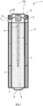
- FIG. 1 illustrates an internal structure of an alkaline battery 1.
- Fig. 1 illustrates a vertical cross section of the alkaline battery 1 oriented such that the cylinder axis 100 extends in an up-down (vertical) direction. As illustrated in Fig.
- the alkaline battery 1 includes a bottomed tubular battery can 2 made of metal, a positive electrode mixture 3 shaped into a cylinder, a bottomed cylindrical separator 4 arranged on the inside of the positive electrode mixture 3, a negative electrode gel 5 containing a zinc alloy and filling the inside of the separator 4, a negative electrode current collector 6 in the form of a metal rod inserted into the negative electrode gel 5, a dish-shaped negative electrode terminal plate 7 made of metal, a sealing gasket 120 made of resin, and the like.
- the positive electrode mixture 3, the separator 4, and the negative electrode gel 5 form a power generation element of the alkaline battery 1 in the presence of an electrolyte.
- the up-down direction is defined such that the bottom portion side of the battery can 2 is the lower side for the sake of description.
- the direction that is orthogonal to the up-down direction and extends outward is defined as the radial direction.
- the battery can 2 is in direct contact with the positive electrode mixture 3 and thereby functions as a battery case and a positive electrode current collector. Then, a positive electrode terminal 8 is formed on a bottom surface of the battery can 2.
- the dish-shaped negative electrode terminal plate 7 has a flanged edge and is fitted and attached to an open end of the battery can 2 via the sealing gasket 120 with the dish facing down, assuming that the positive electrode terminal 8 is on the lower side.
- the negative electrode terminal plate 7 is a sealing plate for closing the opening of the battery can 2.
- the negative electrode terminal plate 7, the negative electrode current collector 6, and the sealing gasket 120 are integrally combined in advance into a sealing unit. Then, the sealing unit is inserted in the battery can 2, the open end of the battery can 2 is subjected to inward diameter reduction processing to fix the sealing gasket 120 in place by crimping. Specifically, the sealing gasket 120 is held between an inner surface of the battery can 2 and an edge of the negative electrode terminal plate 7 to put the battery can 2 into a sealed state.
- Fig. 2 is a view illustrating the structure of the sealing gasket 120 and the up-down direction of the sealing gasket 120 is defined based on the state where the sealing gasket 120 is arranged in the battery can 2.
- Fig. 2 illustrates, in a vertical cross-sectional view, the shape of the sealing gasket 120 before it is fixed by crimping to the open end of the battery can 2.
- the sealing gasket 120 has a cup shape including a wall surface (hereinafter, sometimes referred to as an outer peripheral portion 24) provided to stand upright from the periphery of the disc.
- the center of the disc is a cylindrical boss portion 21 including a hollow portion (hereinafter, sometimes referred to as a boss hole 22) into which the negative electrode current collector 6 is to be press fitted.
- a film-shaped portion (hereinafter, referred to a partition portion 23) extending from an outer periphery of the boss portion 21 to a peripheral edge of the disc seals a housing space for the power generation element in the battery can 2 and an interior of the battery can 2 is divided into upper and lower portions.
- the sealing gasket 120 is arranged in the battery can 2 such that the sealing gasket 120 is seated on the beading portion 9 formed on the upper end side of the battery can 2, and the opening of the battery can 2 is covered with the sealing unit including the sealing gasket 120, the negative electrode terminal plate 7, and the negative electrode current collector 6. Then, the open end of the battery can 2 is subjected to the diameter reduction processing to seal the battery can 2.
- a groove in the shape of a circle concentric with the outer peripheral portion 24 is formed in the partition portion 23 of the sealing gasket 120.
- a groove-shaped thin portion 25 is formed in part of a back surface of the partition portion 23.
- the thin portion 25 functions as an explosion-proof safety mechanism that breaks first when the pressure in the battery can 2 increases abnormally and that eventually allows gas in the battery can 2 responsible for the abnormally-increased inner pressure to be released to the atmosphere via the exhaust holes 10 (see Fig. 1 ) provided in the negative electrode terminal plate 7.
- the partition portion 23 of the sealing gasket 120 is provided with a stress buffer portion 130 that absorbs stress in the inward radial direction exerted on the sealing gasket 120 when the open end of the battery can 2 is subjected to the diameter reduction processing to seal the battery can 2.
- the stress buffer portion 130 has a shape in which part of the partition portion 23 is bent in vertical cross-sectional view.
- the stress buffer portion 130 has a function of causing the disc shape of the partition portion 23 to uniformly deform, thereby suppressing unintentional breakage of the thin portion 25 due to stress imbalance when the stress in the inward radial direction is exerted on the partition portion 23.
- the stress buffer function of the stress buffer portion 130 is provided by the vertical cross-sectional shape of the partition portion 23 in the sealing gasket 120.
- the stress buffer portion 130 which is bent downward to have a U-shaped vertical cross section, in the partition portion 23 between the outer peripheral portion 24 and the boss portion 21.
- Fig. 3 is a vertical cross-sectional view of a sealing gasket 220 including a stress buffer portion 230 with a different shape from that in Fig. 2 .
- a portion extending obliquely upward from an inner periphery toward an outer periphery of the partition portion 23 and then bent obliquely downward to reach the outer peripheral portion 24 is the stress buffer portion 230.
- the stress buffer portion 230 absorbs stress exerted on the partition portion 23 by changing the angles ( ⁇ 1, ⁇ 2) of the bent portions on the upper surface side and the lower surface side of the partition portion 23 when the battery can 2 is sealed.
- the structure of the sealing gasket 220 including the aforementioned stress buffer portion 230 is described in detail in Patent Literature 1 listed below.
- a method of manufacturing the alkaline battery 1 is described in Non-patent Literature 1 listed below.
- the shape of the stress buffer portion (130, 230) is optimized and, when the open end of the battery can 2 is crimped and the sealing plate seals the battery can 2, the stress buffer portion (130, 230) deforms and reliably prevents deformation of the sealing gasket (120, 220) and breakage of the thin portion 25.
- the stress buffer portion (130, 230) is bent to greatly protrude downward in the partition portion 23 to make it easy to deform when the battery can 2 is sealed. Accordingly, with the sealing gasket (120, 220) configured as described above, it is difficult to increase the capacity of the power generation element housing region situated below the lower surface of the partition portion 23 of the sealing gasket (120, 220) in the battery can 2 for housing the power generation element (positive electrode mixture 3, separator 4, negative electrode gel 5, and electrolyte) . Specifically, the sealing gasket (120, 220) configured as described above limits the volume of the power generation element that can be packed in the battery can 2, and thus it is difficult to improve the discharge performance.
- An objective of the present invention is to provide a sealing gasket that reliably absorbs stress generated when an opening portion of a battery can of a tubular battery is sealed by diameter reduction processing and that also allows an increase in the volume of a power generation element packed in the battery can and a tubular battery including the sealing gasket.
- An aspect of the present invention to achieve the above objective is a sealing gasket used in a tubular battery, the sealing gasket including a disc-shaped partition portion; an outer peripheral portion provided to stand from a peripheral edge of the partition portion and held between an open end of a metal battery can and a dish-shaped metal sealing plate; and a plurality of stress buffer portions formed of annular grooves formed concentrically in the partition portion.
- the tubular battery includes the metal battery can having a bottomed tubular shape and has the open end subjected to inward diameter reduction, a power generation element housed in the battery can, the dish-shaped metal sealing plate fitted and attached to the open end subjected to the inward diameter reduction, and the sealing gasket made of resin and held between the open end and the sealing plate.
- Ha/H which is a ratio of a thickness Ha of a region of the partition portion in which the plurality of stress buffer portions are formed to an overall height H, is 15% or more and 30% or less.
- the present invention provides a sealing gasket that can reliably absorbs stress generated when an opening portion of a battery can of a tubular battery is sealed by crimping processing and that also allows an increase in the volume of a power generation element packed in the battery can, and a tubular battery including the sealing gasket.
- FIG. 4 illustrates the structure of a sealing gasket 20 according to the example.
- Fig. 4 is a vertical cross-sectional view of the sealing gasket 20.
- the stress buffer portion (130, 230) is formed in one portion of the partition portion 23 in each of the aforementioned sealing gaskets illustrated in Figs. 2 and 3 (hereinafter, a sealing gasket 120 according to a comparative example 1 and a sealing gasket 220 according to a comparative example 2).
- stress buffer portions (30a, 30b) are formed in multiple portions of the partition portion 23 in the sealing gasket 20 (in this case, two portions).
- the sealing gasket 20 is fabricated by injection molding using a resin such as nylon 6 or 12.
- the stress buffer portions (30a, 30b) formed in annular groove shapes concentric with a boss portion 21 are formed on the upper surface side and the lower surface side of the partition portion 23, respectively.
- the two stress buffer portions (30a, 30b) are formed adjacent to each other with one side wall in between, in the radial direction of the partition portion 23.
- the thickness Ha of the region of the partition portion 23 in which the stress buffer portions (30a, 30b) are formed is set as appropriate, increasing the internal capacity of the tubular alkaline battery 1 including the sealing gasket 20 for housing the power generation element for improved discharge capacity, as well as ensuring that, when the pressure inside the battery can 2 reaches a certain pressure, a thin portion 25 serving as a safety valve will break to ensure safety.
- Fig. 5 illustrates a vertical cross-sectional view of the LR6 alkaline battery 1 including the sealing gasket 20 according to the example. As illustrated in Fig.
- the sealing gasket 20 when the sealing gasket 20 according to the example is crimped to the open end of the battery can 2 via the negative electrode terminal plate 7, the sealing gasket 20 deforms such that openings of grooves forming the respective two stress buffer portions (30a, 30b) are closed (in other words, the width of the grooves becomes smaller), and absorbs stress exerted on the partition portion 23 in the diameter reducing direction (radially inward radiation direction or radial direction). This suppresses deformation in the region inside the stress buffer portions (30a, 30b) of the partition portion 23 and can prevent breakage of the thin portion 25 formed around the boss portion 21.
- sealing gasket 120 according to the comparative example 1 illustrated in Fig. 2
- sealing gasket 220 according to the comparative example 2 illustrated in Fig. 3
- various sealing gaskets hereinafter, referred to as gaskets 20 according to the embodiment in some cases
- gaskets 20 varying in the thickness Ha of the stress buffer portions (30a, 30b) in the sealing gasket 20 according to the example illustrated in Fig. 4
- sealing gaskets 320 according to a comparative example 3 that each include only one stress buffer portion 30a out of the two stress buffer portions (30a, 30b), in contrast to the gaskets 20 according to the embodiment.
- the sizes of portions corresponding to one another in the sealing gaskets (120, 220, 20, 320) illustrated in the respective drawings are denoted by the same reference signs.
- the various types of fabricated sealing gaskets (120, 220, 20, 320) were made of the same resin material and had the same overall height H and the same outer diameter ⁇ .
- the sizes of portions other than the stress buffer portions (130, 230, 30a, 30b), for example, the boss portion (height Hb, outer diameter ⁇ 1, inner diameter ⁇ 2), the outer peripheral portion (height Hc, thickness t), and the like were the same.
- the sizes of the corresponding portions were the same except for the thickness of the stress buffer portions (30a, 30b) (hereinafter, also referred to as buffer portion height Ha).
- the depths of the grooves of the two annular groove-shaped stress buffer portions (30a, 30b) in the gaskets 20 according to the embodiment were dimensions depending on the buffer portion height Ha and were adjusted such that the portions corresponding to the bottoms of the grooves had the same thickness. Accordingly, in the case where the buffer portion height Ha was small, the depth was small.
- the setting in which the portions corresponding to the bottoms of the grooves have the same thickness allows these portions to exhibit the same degree of buffer performance when the gasket 20 is fixed to the open end of the battery can 2 by crimping and is deformed.
- the thickness of the thinnest portion in the region in which the stress buffer portions (30a, 30b) were formed was equal to or greater than the thickness of the thin portion 25 that functions as the safety valve.
- the thickness of the thin portion 25 in each type of fabricated sealing gasket (120, 220, 20, 320) was set based on mechanical properties (tensile strength, compressive strength, bending strength, and the like) of the material (nylon 6 or 12 or the like) forming the sealing gasket (120, 220, 20, 320) such that the thin portion 25 breaks in a predetermined pressure range.
- the overall height H, the height Hb of the boss portion 21, the height Hc of the outer peripheral portion 24, the diameter ⁇ , the outer diameter ⁇ 1 of the boss portion 21, the inner diameter ⁇ 2 of the boss portion 21, and the thickness t of the outer peripheral portion 24 were the same for all the various types of fabricated sealing gaskets (120, 220, 20, 320).
- the high temperature storage test was performed to evaluate a long-term storage performance of the alkaline battery 1.
- samples that housed a power generation element in the battery cans 2 were stored for 30 days at a temperature of 90°C and whether liquid had leaked or not was visually checked. If there were one or more individual specimens exhibiting liquid leakage among the 20 individual specimens, it was determined that this sample failed the test.
- the sample 1 is the alkaline battery 1 including the sealing gasket 120 according to the comparative example 1 illustrated in Fig. 2 and the sample 2 is the alkaline battery 1 including the sealing gasket 220 according to the comparative example 2 illustrated in Fig. 3 .
- the samples 3 to 5 are each the alkaline battery 1 including the sealing gasket 320 according to the comparative example 3 illustrated in Fig. 6 .
- the samples 6 to 10 are each the alkaline battery 1 including the gasket 20 according to the embodiment having a structure the same as or similar to that illustrated in Fig. 4 .
- Ha/H in Table 1 is the ratio Ha/H of the thickness Ha of the region in which the stress buffer portions (130, 230, 30a, 30b) were formed to the overall height H in each of the sealing gaskets (120, 220, 20, 320), expressed as a percentage (%).
- the samples 1 and 2 are both LR6 alkaline batteries 1 commercially provided as products and have substantially the same capacity.
- the ratios Ha/H of the samples 1 and 2 were 42% and 40%, respectively.
- the safety valves in the samples 1 and 2 operated at specified pressures and the samples 1 and 2 also passed a liquid leakage resistance test.
- appropriate values of Ha/H in the sealing gaskets (120, 220) according to the comparative examples 1 and 2 are 42% and 40%, respectively, and, in the case where the ratios Ha/H are greater than the respective appropriate values, the capacity decreases and it is difficult to provide satisfactory discharge performance.
- the stress buffer portion (130, 230) it is difficult for the stress buffer portion (130, 230) to sufficiently absorb the stress when the battery can 2 is sealed, and the partition portion 23 tends to deform. Accordingly, the pressure at which the safety valve operates may be out of specification. Moreover, if the sealing gasket falls into a state where excessive stress is constantly exerted on the partition portion 23 due to the stress in sealing the battery can 2, there is also a possibility that part of the thin portion 25 to serve as the safety valve may deteriorate more quickly than the other portions in the high temperature storage test, causing liquid leakage due to cracking of the thin portion 25.
- the stress buffer portion (30a) of the sealing gasket (320) is formed within the range of the thickness of the partition portion 23, and thus it is easy to increase the capacity of the power generation element housing region. In the case where Ha/H ⁇ 30%, the capacity of the power generation element housing region can be greater than those in the samples 1 and 2.
- the stress buffer portions (30a, 30b) of the sealing gasket 20 are formed within the range of the thickness of the partition portion 23 as in the comparative example 3, and thus it is easy to increase the capacity of the power generation element housing region.
- the capacity of the power generation element housing region can be greater than those in the samples 1 and 2.
- the power generation element housing region was unable to have a greater capacity than those in the samples 1 and 2.
- the sealing gasket 20 according to the embodiment is thus configured such that the multiple annular groove-shaped stress buffer portions (30a, 30b) concentric with the boss portion 21 are formed in part of the disc-shaped partition portion 23 and the ratio Ha/H of the maximum thickness Ha of the region in which the stress buffer portions (30a, 30b) are formed to the overall height H is 15% or more and 30% or less.
- both of the stress buffer portions (30a, 30b) may be formed on one of the upper surface and the lower surface of the partition portion 23.
- the sealing gasket 20 may include three or more stress buffer portions.
- the partition portion 23 with a limited projected area in the up-down direction is provided with many stress buffer portions (30a, 30b)
- the width of a groove forming each of the stress buffer portions (30a, 30b) decreases, making it difficult to secure molding accuracy.
- the number of the stress buffer portions (30a, 30b) is determined as appropriate in consideration of dimension accuracy in manufacturing the sealing gasket 20 and other factors.
- the number of stress buffer portions (30a, 30b) since the configuration in which the number of stress buffer portions (30a, 30b) is two that is the minimum required number can secure satisfactory explosion-proof safety performance while allowing an increase in the capacity of the power generation element housing region, it is more preferable that the number of the stress buffer portions (30a, 30b) be two.
- the sealing gasket 20 according to the aforementioned embodiment is not limited to the alkaline battery 1 but can be applied to various tubular batteries in which a sealing plate is fitted and attached to the open end of the battery can 2 by subjecting the open end of the battery can 2 to the diameter reduction processing.
Landscapes
- Chemical & Material Sciences (AREA)
- Chemical Kinetics & Catalysis (AREA)
- Electrochemistry (AREA)
- General Chemical & Material Sciences (AREA)
- Engineering & Computer Science (AREA)
- Manufacturing & Machinery (AREA)
- Sealing Battery Cases Or Jackets (AREA)
- Primary Cells (AREA)
- Battery Electrode And Active Subsutance (AREA)
Abstract
Description
- The present invention relates to a sealing gasket and a tubular battery.
- A general LR6 alkaline battery is given as an example of a tubular battery including a sealing gasket.
Fig. 1 illustrates an internal structure of analkaline battery 1.Fig. 1 illustrates a vertical cross section of thealkaline battery 1 oriented such that thecylinder axis 100 extends in an up-down (vertical) direction. As illustrated inFig. 1 , thealkaline battery 1 includes a bottomed tubular battery can 2 made of metal, apositive electrode mixture 3 shaped into a cylinder, a bottomedcylindrical separator 4 arranged on the inside of thepositive electrode mixture 3, anegative electrode gel 5 containing a zinc alloy and filling the inside of theseparator 4, a negative electrodecurrent collector 6 in the form of a metal rod inserted into thenegative electrode gel 5, a dish-shaped negativeelectrode terminal plate 7 made of metal, a sealinggasket 120 made of resin, and the like. - In this structure, the
positive electrode mixture 3, theseparator 4, and thenegative electrode gel 5 form a power generation element of thealkaline battery 1 in the presence of an electrolyte. Note that, in the following description, the up-down direction is defined such that the bottom portion side of the battery can 2 is the lower side for the sake of description. Moreover, the direction that is orthogonal to the up-down direction and extends outward is defined as the radial direction. These two directions indicate the relative directional relationship determined for the sake of convenience. - The battery can 2 is in direct contact with the
positive electrode mixture 3 and thereby functions as a battery case and a positive electrode current collector. Then, apositive electrode terminal 8 is formed on a bottom surface of the battery can 2. The dish-shaped negativeelectrode terminal plate 7 has a flanged edge and is fitted and attached to an open end of the battery can 2 via the sealinggasket 120 with the dish facing down, assuming that thepositive electrode terminal 8 is on the lower side. - An upper end of the rod-shaped negative electrode
current collector 6 inserted in thenegative electrode gel 5 is welded to a lower surface of the dish-shaped negativeelectrode terminal plate 7. Note that the negativeelectrode terminal plate 7 is a sealing plate for closing the opening of the battery can 2. The negativeelectrode terminal plate 7, the negative electrodecurrent collector 6, and the sealinggasket 120 are integrally combined in advance into a sealing unit. Then, the sealing unit is inserted in the battery can 2, the open end of the battery can 2 is subjected to inward diameter reduction processing to fix the sealinggasket 120 in place by crimping. Specifically, the sealinggasket 120 is held between an inner surface of the battery can 2 and an edge of the negativeelectrode terminal plate 7 to put the battery can 2 into a sealed state. -
Fig. 2 is a view illustrating the structure of the sealinggasket 120 and the up-down direction of the sealinggasket 120 is defined based on the state where the sealinggasket 120 is arranged in the battery can 2.Fig. 2 illustrates, in a vertical cross-sectional view, the shape of the sealinggasket 120 before it is fixed by crimping to the open end of the battery can 2. The sealinggasket 120 has a cup shape including a wall surface (hereinafter, sometimes referred to as an outer peripheral portion 24) provided to stand upright from the periphery of the disc. The center of the disc is acylindrical boss portion 21 including a hollow portion (hereinafter, sometimes referred to as a boss hole 22) into which the negative electrodecurrent collector 6 is to be press fitted. Then, when the sealinggasket 120 is incorporated into the battery can 2, a film-shaped portion (hereinafter, referred to a partition portion 23) extending from an outer periphery of theboss portion 21 to a peripheral edge of the disc seals a housing space for the power generation element in the battery can 2 and an interior of the battery can 2 is divided into upper and lower portions. - As a procedure of sealing the battery can 2, first the negative
electrode terminal plate 7, the negativeelectrode current collector 6, and thesealing gasket 120 are integrally combined in advance into the sealing unit. Next, the sealinggasket 120 is arranged in the battery can 2 such that thesealing gasket 120 is seated on the beadingportion 9 formed on the upper end side of the battery can 2, and the opening of the battery can 2 is covered with the sealing unit including the sealinggasket 120, the negativeelectrode terminal plate 7, and the negative electrodecurrent collector 6. Then, the open end of the battery can 2 is subjected to the diameter reduction processing to seal the battery can 2. - A groove in the shape of a circle concentric with the outer
peripheral portion 24 is formed in thepartition portion 23 of the sealinggasket 120. For example, a groove-shapedthin portion 25 is formed in part of a back surface of thepartition portion 23. Thethin portion 25 functions as an explosion-proof safety mechanism that breaks first when the pressure in the battery can 2 increases abnormally and that eventually allows gas in the battery can 2 responsible for the abnormally-increased inner pressure to be released to the atmosphere via the exhaust holes 10 (seeFig. 1 ) provided in the negativeelectrode terminal plate 7. - Moreover, the
partition portion 23 of thesealing gasket 120 is provided with astress buffer portion 130 that absorbs stress in the inward radial direction exerted on thesealing gasket 120 when the open end of the battery can 2 is subjected to the diameter reduction processing to seal the battery can 2. Thestress buffer portion 130 has a shape in which part of thepartition portion 23 is bent in vertical cross-sectional view. Thestress buffer portion 130 has a function of causing the disc shape of thepartition portion 23 to uniformly deform, thereby suppressing unintentional breakage of thethin portion 25 due to stress imbalance when the stress in the inward radial direction is exerted on thepartition portion 23. - The stress buffer function of the
stress buffer portion 130 is provided by the vertical cross-sectional shape of thepartition portion 23 in the sealinggasket 120. In the sealinggasket 120 illustrated inFig. 2 , there is formed thestress buffer portion 130, which is bent downward to have a U-shaped vertical cross section, in thepartition portion 23 between the outerperipheral portion 24 and theboss portion 21. When the open end of the battery can 2 is subjected to the diameter reduction and the sealinggasket 120 is fixed by crimping, thestress buffer portion 130 deforms such that an opening of the U-shape in the vertical cross section closes, and thereby absorbs stress exerted on thepartition portion 23 in the diameter reducing direction. -
Fig. 3 is a vertical cross-sectional view of a sealinggasket 220 including astress buffer portion 230 with a different shape from that inFig. 2 . In thesealing gasket 220 illustrated inFig. 3 , a portion extending obliquely upward from an inner periphery toward an outer periphery of thepartition portion 23 and then bent obliquely downward to reach the outerperipheral portion 24 is thestress buffer portion 230. Thestress buffer portion 230 absorbs stress exerted on thepartition portion 23 by changing the angles (θ1, θ2) of the bent portions on the upper surface side and the lower surface side of thepartition portion 23 when the battery can 2 is sealed. The structure of the sealinggasket 220 including the aforementionedstress buffer portion 230 is described in detail inPatent Literature 1 listed below. Moreover, a method of manufacturing thealkaline battery 1 is described in Non-patentLiterature 1 listed below. - [PTL 1]
Japanese Patent Application Publication No. 2013-69459 - [NPL 1] FDK Corporation's "How an Alkaline Battery Is Manufactured" retrived online on December 26, 2018, at www.fdk.co.jp/denchi_club/denchi_story/arukari
- In each of the sealing gaskets (120, 220) illustrated in
Figs. 2 and 3 , the shape of the stress buffer portion (130, 230) is optimized and, when the open end of the battery can 2 is crimped and the sealing plate seals the battery can 2, the stress buffer portion (130, 230) deforms and reliably prevents deformation of the sealing gasket (120, 220) and breakage of thethin portion 25. - However, the stress buffer portion (130, 230) is bent to greatly protrude downward in the
partition portion 23 to make it easy to deform when the battery can 2 is sealed. Accordingly, with the sealing gasket (120, 220) configured as described above, it is difficult to increase the capacity of the power generation element housing region situated below the lower surface of thepartition portion 23 of the sealing gasket (120, 220) in the battery can 2 for housing the power generation element (positive electrode mixture 3,separator 4,negative electrode gel 5, and electrolyte) . Specifically, the sealing gasket (120, 220) configured as described above limits the volume of the power generation element that can be packed in the battery can 2, and thus it is difficult to improve the discharge performance. - An objective of the present invention is to provide a sealing gasket that reliably absorbs stress generated when an opening portion of a battery can of a tubular battery is sealed by diameter reduction processing and that also allows an increase in the volume of a power generation element packed in the battery can and a tubular battery including the sealing gasket.
- An aspect of the present invention to achieve the above objective is a sealing gasket used in a tubular battery, the sealing gasket including a disc-shaped partition portion; an outer peripheral portion provided to stand from a peripheral edge of the partition portion and held between an open end of a metal battery can and a dish-shaped metal sealing plate; and a plurality of stress buffer portions formed of annular grooves formed concentrically in the partition portion. The tubular battery includes the metal battery can having a bottomed tubular shape and has the open end subjected to inward diameter reduction, a power generation element housed in the battery can, the dish-shaped metal sealing plate fitted and attached to the open end subjected to the inward diameter reduction, and the sealing gasket made of resin and held between the open end and the sealing plate. Ha/H, which is a ratio of a thickness Ha of a region of the partition portion in which the plurality of stress buffer portions are formed to an overall height H, is 15% or more and 30% or less.
- The present invention provides a sealing gasket that can reliably absorbs stress generated when an opening portion of a battery can of a tubular battery is sealed by crimping processing and that also allows an increase in the volume of a power generation element packed in the battery can, and a tubular battery including the sealing gasket.
-
- [
Fig. 1] Fig. 1 is a view illustrating the structure of a general alkaline battery. - [
Fig. 2] Fig. 2 is a view illustrating an example of a sealing gasket configured to be incorporated in the aforementioned general alkaline battery. - [
Fig. 3] Fig. 3 is a view illustrating another example of a sealing gasket configured to be incorporated in the aforementioned general alkaline battery. - [
Fig. 4] Fig. 4 is a view illustrating a sealing gasket according to an embodiment of the present invention. - [
Fig. 5] Fig. 5 is a view illustrating an alkaline battery including the sealing gasket according to the aforementioned embodiment. - [
Fig. 6] Fig. 6 is a view illustrating a sealing gasket according to a comparative example. - This application claims priority based on
Japanese Patent Application No. 2019-011488, filed on January 25, 2019 - An embodiment of the present invention is described below with reference to the attached drawings. Note that, in the drawings used in the following description, in some cases the same or similar parts are denoted by the same reference signs and repetitive description thereof is omitted. Unnecessary reference signs may be omitted in description of some drawings.
- A sealing gasket according to the embodiment of the present invention is described based on a sealing gasket used in an LR6 alkaline battery.
Fig. 4 illustrates the structure of a sealinggasket 20 according to the example.Fig. 4 is a vertical cross-sectional view of the sealinggasket 20. Note that the stress buffer portion (130, 230) is formed in one portion of thepartition portion 23 in each of the aforementioned sealing gaskets illustrated inFigs. 2 and 3 (hereinafter, a sealinggasket 120 according to a comparative example 1 and a sealinggasket 220 according to a comparative example 2). In contrast, according to the embodiment as illustrated inFig. 4 , stress buffer portions (30a, 30b) are formed in multiple portions of thepartition portion 23 in the sealing gasket 20 (in this case, two portions). - Specifically, the sealing
gasket 20 according to the present embodiment is fabricated by injection molding using a resin such asnylon 6 or 12. The stress buffer portions (30a, 30b) formed in annular groove shapes concentric with aboss portion 21 are formed on the upper surface side and the lower surface side of thepartition portion 23, respectively. Moreover, the two stress buffer portions (30a, 30b) are formed adjacent to each other with one side wall in between, in the radial direction of thepartition portion 23. - In the sealing
gasket 20 according to the example, as illustrated inFig. 4 , the thickness Ha of the region of thepartition portion 23 in which the stress buffer portions (30a, 30b) are formed is set as appropriate, increasing the internal capacity of the tubularalkaline battery 1 including the sealinggasket 20 for housing the power generation element for improved discharge capacity, as well as ensuring that, when the pressure inside the battery can 2 reaches a certain pressure, athin portion 25 serving as a safety valve will break to ensure safety.Fig. 5 illustrates a vertical cross-sectional view of the LR6alkaline battery 1 including the sealinggasket 20 according to the example. As illustrated inFig. 5 , when the sealinggasket 20 according to the example is crimped to the open end of the battery can 2 via the negativeelectrode terminal plate 7, the sealinggasket 20 deforms such that openings of grooves forming the respective two stress buffer portions (30a, 30b) are closed (in other words, the width of the grooves becomes smaller), and absorbs stress exerted on thepartition portion 23 in the diameter reducing direction (radially inward radiation direction or radial direction). This suppresses deformation in the region inside the stress buffer portions (30a, 30b) of thepartition portion 23 and can prevent breakage of thethin portion 25 formed around theboss portion 21. - Next, in order to evaluate the performance of the sealing
gasket 20 according to the example, there were fabricated the sealinggasket 120 according to the comparative example 1 illustrated inFig. 2 , the sealinggasket 220 according to the comparative example 2 illustrated inFig. 3 , and various sealing gaskets (hereinafter, referred to asgaskets 20 according to the embodiment in some cases) varying in the thickness Ha of the stress buffer portions (30a, 30b) in the sealinggasket 20 according to the example illustrated inFig. 4 . Moreover, as illustrated inFig. 6 , there were fabricated sealinggaskets 320 according to a comparative example 3 that each include only onestress buffer portion 30a out of the two stress buffer portions (30a, 30b), in contrast to thegaskets 20 according to the embodiment. - Note that, in
Figs. 2 to 4 and6 , the sizes of portions corresponding to one another in the sealing gaskets (120, 220, 20, 320) illustrated in the respective drawings are denoted by the same reference signs. The various types of fabricated sealing gaskets (120, 220, 20, 320) were made of the same resin material and had the same overall height H and the same outer diameter ϕ. Moreover, the sizes of portions other than the stress buffer portions (130, 230, 30a, 30b), for example, the boss portion (height Hb, outer diameter ϕ1, inner diameter ϕ2), the outer peripheral portion (height Hc, thickness t), and the like were the same. - Among the
gaskets 20 according to the embodiment, the sizes of the corresponding portions were the same except for the thickness of the stress buffer portions (30a, 30b) (hereinafter, also referred to as buffer portion height Ha). Moreover, the depths of the grooves of the two annular groove-shaped stress buffer portions (30a, 30b) in thegaskets 20 according to the embodiment were dimensions depending on the buffer portion height Ha and were adjusted such that the portions corresponding to the bottoms of the grooves had the same thickness. Accordingly, in the case where the buffer portion height Ha was small, the depth was small. The setting in which the portions corresponding to the bottoms of the grooves have the same thickness allows these portions to exhibit the same degree of buffer performance when thegasket 20 is fixed to the open end of the battery can 2 by crimping and is deformed. - The thickness of the thinnest portion in the region in which the stress buffer portions (30a, 30b) were formed was equal to or greater than the thickness of the
thin portion 25 that functions as the safety valve. Note that the thickness of thethin portion 25 in each type of fabricated sealing gasket (120, 220, 20, 320) was set based on mechanical properties (tensile strength, compressive strength, bending strength, and the like) of the material (nylon 6 or 12 or the like) forming the sealing gasket (120, 220, 20, 320) such that thethin portion 25 breaks in a predetermined pressure range. - Moreover, the overall height H, the height Hb of the
boss portion 21, the height Hc of the outerperipheral portion 24, the diameter ϕ, the outer diameter ϕ1 of theboss portion 21, the inner diameter ϕ2 of theboss portion 21, and the thickness t of the outerperipheral portion 24 were the same for all the various types of fabricated sealing gaskets (120, 220, 20, 320). - To evaluate characteristics of the aforementioned various types of sealing gaskets (120, 220, 20, 320), there were fabricated samples in which the
LR6 battery cans 2 were sealed with various types of sealing units including these sealing gaskets (120, 220, 20, 320). Then, for each of the samples, the capacity of the housing region for the power generation element (hereinafter, referred to as simply capacity in some cases) was investigated, and an operation test of the safety valve (thin portion 25) and a high temperature storage test were performed. Note that the operation test of the safety valve was performed using samples that did not house a power generation element in thebattery cans 2 whereas the high temperature storage test was performed using samples that housed a power generation element in thebattery cans 2. - Moreover, the operation test of the safety valve (thin portion 25) and the high temperature storage test were performed for each sample by using 20 individual sample specimens.
- In the operation test of the safety valve (thin portion 25), samples of the
battery cans 2 that had been sealed without housing a power generation element were used. Then, compressed air was introduced into the housing region for a power generation element in each sample, and the pressure at which the safety valve operated was investigated. Then, if the pressure at which the safety valve broke was within a predetermined numerical range for 20 individual specimens belonging to the same sample, it was determined that this sample passed the test. If there were one or more individual specimens whose safety valve broke outside the numerical range among all individual specimens, it was determined that this sample failed the test. - The high temperature storage test was performed to evaluate a long-term storage performance of the
alkaline battery 1. In this test, samples that housed a power generation element in thebattery cans 2 were stored for 30 days at a temperature of 90°C and whether liquid had leaked or not was visually checked. If there were one or more individual specimens exhibiting liquid leakage among the 20 individual specimens, it was determined that this sample failed the test. - Test results for each of the samples are illustrated in the following Table 1.
[Table 1] Sample Sealing gasket (structure) Stress buffer portion (number of portions) Ha/H (%) Capacity Safety valve operation test High temperature storage test 1 Comparative example 1 - 42 - Passed Passed 2 Comparative example 2 - 40 - Passed Passed 3 Comparative example 3 1 10 Passed Failed Failed 4 Comparative example 3 1 20 Passed Failed Failed 5 Comparative example 3 1 30 Passed Failed Failed 6 Embodiment 2 10 Passed Failed Failed 7 Embodiment 2 15 Passed Passed Passed 8 Embodiment 2 20 Passed Passed Passed 9 Embodiment 2 30 Passed Passed Passed 10 Embodiment 2 40 Failed Passed Passed - In Table 1, the
sample 1 is thealkaline battery 1 including the sealinggasket 120 according to the comparative example 1 illustrated inFig. 2 and thesample 2 is thealkaline battery 1 including the sealinggasket 220 according to the comparative example 2 illustrated inFig. 3 . Thesamples 3 to 5 are each thealkaline battery 1 including the sealinggasket 320 according to the comparative example 3 illustrated inFig. 6 . Then, thesamples 6 to 10 are each thealkaline battery 1 including thegasket 20 according to the embodiment having a structure the same as or similar to that illustrated inFig. 4 . - Moreover, as illustrated in
Figs. 2 to 4 and6 , "Ha/H" in Table 1 is the ratio Ha/H of the thickness Ha of the region in which the stress buffer portions (130, 230, 30a, 30b) were formed to the overall height H in each of the sealing gaskets (120, 220, 20, 320), expressed as a percentage (%). The greater the value of Ha/H is, the smaller the capacity of the housing region for the power generation element is. - In Table 1, the
samples alkaline batteries 1 commercially provided as products and have substantially the same capacity. The ratios Ha/H of thesamples samples samples partition portion 23 tends to deform. Accordingly, the pressure at which the safety valve operates may be out of specification. Moreover, if the sealing gasket falls into a state where excessive stress is constantly exerted on thepartition portion 23 due to the stress in sealing the battery can 2, there is also a possibility that part of thethin portion 25 to serve as the safety valve may deteriorate more quickly than the other portions in the high temperature storage test, causing liquid leakage due to cracking of thethin portion 25. - In each of the
samples 3 to 5 including the sealinggasket 320 according to the comparative example 3 illustrated inFig. 6 , the stress buffer portion (30a) of the sealing gasket (320) is formed within the range of the thickness of thepartition portion 23, and thus it is easy to increase the capacity of the power generation element housing region. In the case where Ha/H ≤ 30%, the capacity of the power generation element housing region can be greater than those in thesamples samples 3 to 5 including the sealinggasket 320 according to the comparative example 3, there were one or more individual specimens whose safety valve (thin portion 25) broke at a pressure out of the specification and one or more individual specimens that exhibited liquid leakage in the high temperature storage characteristic. The reason for this is assumed to be that the sealinggasket 320 according to the comparative example 3 includes only onestress buffer portion 30a and was unable to sufficiently absorb the stress in sealing the battery can 2. - In each of the
samples 6 to 10 including the sealinggasket 20 according to the embodiment, the stress buffer portions (30a, 30b) of the sealinggasket 20 are formed within the range of the thickness of thepartition portion 23 as in the comparative example 3, and thus it is easy to increase the capacity of the power generation element housing region. In the case where Ha/H ≤ 30%, the capacity of the power generation element housing region can be greater than those in thesamples sample 10 in which Ha/H = 40%, the power generation element housing region was unable to have a greater capacity than those in thesamples samples 7 to 9 in which 15% ≤ Ha/H ≤ 30% among thesamples 6 to 9 which included thegasket 20 according to the embodiment and in which the capacity of the power generation element housing region was greater than those in thesamples sample 6 in which Ha/H = 10%, the pressure at which the safety valve worked was out of the specification and liquid leakage occurred in the high temperature storage test. The reason for this is assumed to be that since in thesample 6, the thickness of the region of the sealinggasket 20 in which the stress buffer portions (30a, 30b) are formed is small, thepartition portion 23 deformed greatly in this region by a slight change in stress. - The sealing
gasket 20 according to the embodiment is thus configured such that the multiple annular groove-shaped stress buffer portions (30a, 30b) concentric with theboss portion 21 are formed in part of the disc-shapedpartition portion 23 and the ratio Ha/H of the maximum thickness Ha of the region in which the stress buffer portions (30a, 30b) are formed to the overall height H is 15% or more and 30% or less. - Although the two stress buffer portions (30a, 30b) adjacent to each other in the radial direction are offset from each other on the upper surface (one surface) and the lower surface (the other surface), respectively, of the
partition portion 23 in the sealinggasket 20 according to the aforementioned embodiment, alternatively both of the stress buffer portions (30a, 30b) may be formed on one of the upper surface and the lower surface of thepartition portion 23. - Further alternatively, although the sealing
gasket 20 according to the aforementioned embodiment includes two stress buffer portions (30a, 30b), the sealing gasket may include three or more stress buffer portions. Note that, if thepartition portion 23 with a limited projected area in the up-down direction is provided with many stress buffer portions (30a, 30b), the width of a groove forming each of the stress buffer portions (30a, 30b) decreases, making it difficult to secure molding accuracy. Accordingly, the number of the stress buffer portions (30a, 30b) is determined as appropriate in consideration of dimension accuracy in manufacturing the sealinggasket 20 and other factors. Moreover, as illustrated in Table 1, since the configuration in which the number of stress buffer portions (30a, 30b) is two that is the minimum required number can secure satisfactory explosion-proof safety performance while allowing an increase in the capacity of the power generation element housing region, it is more preferable that the number of the stress buffer portions (30a, 30b) be two. - The sealing
gasket 20 according to the aforementioned embodiment is not limited to thealkaline battery 1 but can be applied to various tubular batteries in which a sealing plate is fitted and attached to the open end of the battery can 2 by subjecting the open end of the battery can 2 to the diameter reduction processing. - The above-described embodiments are intended to facilitate an understanding of the present invention and are not in any way to be construed as limiting the present invention. The present invention may be modified and improved without departing from the scope of the invention, and equivalents thereof are also encompassed by the invention.
-
- 1
- alkaline battery
- 2
- battery can
- 3
- positive electrode mixture
- 4
- separator
- 5
- negative electrode gel
- 6
- negative electrode current collector
- 7
- negative electrode terminal plate
- 8
- positive electrode terminal
- 9
- beading portion
- 20, 120, 220, 320
- sealing gasket
- 21
- boss portion
- 22
- boss hole
- 23
- partition portion
- 24
- outer peripheral portion
- 25
- thin portion
- 30a, 30b, 130, 230
- stress buffer portion
- 40
- outer peripheral portion
Claims (4)
- A sealing gasket for a tubular battery, the sealing gasket comprising:a disc-shaped partition portion;an outer peripheral portion provided to stand from a peripheral edge of the partition portion and held between an open end of a metal battery can and a dish-shaped metal sealing plate; anda plurality of stress buffer portions formed of annular grooves formed concentrically in the partition portion,the tubular battery includingthe metal battery can having a bottomed tubular shape and has the open end subjected to inward diameter reduction,a power generation element housed in the battery can, the dish-shaped metal sealing plate fitted and attached to the open end subjected to the inward diameter reduction, andthe sealing gasket, made of resin and held between the open end and the sealing plate,wherein Ha/H, a ratio of a thickness Ha of a region of the partition portion in which the plurality of stress buffer portions are formed to an overall height H from a lowest position to a highest position of the sealing gasket, is 15% or more and 30% or less.
- The sealing gasket according to claim 1, wherein
the number of the stress buffer portions is two. - The sealing gasket according to claim 1 or 2, wherein
the stress buffer portions are offset from each other and formed alternately on one surface and the other surface of the partition portion. - A tubular battery comprising:a metal battery can having a bottomed tubular shape and an open end subjected to inward diameter reduction;a power generation element housed in the battery can;a dish-shaped metal sealing plate fitted and attached to the open end subjected to the inward diameter reduction; anda sealing gasket made of resin and held between the open end and the sealing plate,the sealing gasket includinga disc-shaped partition portion,an outer peripheral portion provided to stand from a peripheral edge of the partition portion and held between the open end and the sealing plate, anda plurality of stress buffer portions formed of annular grooves formed concentrically in the partition portion,wherein Ha/H, a ratio of a thickness Ha of a region of the partition portion in which the plurality of stress buffer portions are formed to an overall height H from a lowest position to a highest position of the sealing gasket, is 15% or more and 30% or less.
Applications Claiming Priority (2)
| Application Number | Priority Date | Filing Date | Title |
|---|---|---|---|
| JP2019011488A JP7274877B2 (en) | 2019-01-25 | 2019-01-25 | Sealing gaskets and cylindrical batteries |
| PCT/JP2019/050912 WO2020153089A1 (en) | 2019-01-25 | 2019-12-25 | Sealing gasket and cylindrical battery |
Publications (2)
| Publication Number | Publication Date |
|---|---|
| EP3916863A1 true EP3916863A1 (en) | 2021-12-01 |
| EP3916863A4 EP3916863A4 (en) | 2023-03-29 |
Family
ID=71736789
Family Applications (1)
| Application Number | Title | Priority Date | Filing Date |
|---|---|---|---|
| EP19912042.9A Pending EP3916863A4 (en) | 2019-01-25 | 2019-12-25 | GASKET AND CYLINDRICAL BATTERY |
Country Status (5)
| Country | Link |
|---|---|
| US (1) | US12244027B2 (en) |
| EP (1) | EP3916863A4 (en) |
| JP (1) | JP7274877B2 (en) |
| CN (2) | CN113330615A (en) |
| WO (1) | WO2020153089A1 (en) |
Families Citing this family (3)
| Publication number | Priority date | Publication date | Assignee | Title |
|---|---|---|---|---|
| JPWO2022045229A1 (en) * | 2020-08-31 | 2022-03-03 | ||
| JP7248915B2 (en) * | 2020-09-11 | 2023-03-30 | ダイキン工業株式会社 | Sealing member and cylindrical lithium ion battery |
| JP2023172029A (en) * | 2022-05-23 | 2023-12-06 | Fdk株式会社 | Batteries and gaskets |
Family Cites Families (17)
| Publication number | Priority date | Publication date | Assignee | Title |
|---|---|---|---|---|
| US5080985A (en) * | 1989-12-07 | 1992-01-14 | Duracell Inc. | High pressure seal for alkaline cells |
| US5227261A (en) * | 1991-10-15 | 1993-07-13 | Eveready Battery Company, Inc. | Cylindrical electrochemical cells with a diaphragm seal |
| JP3732945B2 (en) * | 1998-03-31 | 2006-01-11 | 三洋電機株式会社 | Sealed battery |
| JP3948120B2 (en) * | 1998-06-15 | 2007-07-25 | ソニー株式会社 | Gasket, gasket molding method, and cylindrical alkaline battery using the gasket |
| JP2002190285A (en) * | 2000-12-20 | 2002-07-05 | Toshiba Battery Co Ltd | Cylindrical alkaline battery |
| JP4186468B2 (en) * | 2002-01-21 | 2008-11-26 | Fdk株式会社 | Sealing gasket for alkaline batteries |
| JP2007048730A (en) | 2005-07-15 | 2007-02-22 | Matsushita Electric Ind Co Ltd | Alkaline battery |
| JP5409072B2 (en) * | 2009-03-27 | 2014-02-05 | パナソニック株式会社 | Battery gasket and alkaline battery using the same |
| JP5679181B2 (en) * | 2010-02-22 | 2015-03-04 | Fdkエナジー株式会社 | Gasket for cylindrical battery, cylindrical battery |
| JP5797070B2 (en) * | 2011-09-21 | 2015-10-21 | Fdkエナジー株式会社 | Cylindrical battery |
| CN203406346U (en) * | 2013-07-24 | 2014-01-22 | 嘉兴恒威电池有限公司 | Alkaline battery seal ring |
| CN204155977U (en) * | 2014-11-12 | 2015-02-11 | 四川长虹新能源科技有限公司 | Alkaline dry battery sealing ring |
| JP6698279B2 (en) * | 2015-03-31 | 2020-05-27 | Fdk株式会社 | Cylindrical battery |
| JP2018524793A (en) * | 2015-05-04 | 2018-08-30 | シン フィルム エレクトロニクス エーエスエー | MOSCAP based circuit for wireless communication devices and method of making and using the same |
| US10673033B2 (en) * | 2015-08-24 | 2020-06-02 | Tesla, Inc. | Gasket and diaphragm for electrochemical cell |
| CN109088013A (en) * | 2017-06-13 | 2018-12-25 | 宁波光华电池有限公司 | A kind of alkaline zinc-manganese battery and its sealing body sealing ring |
| JP6880404B2 (en) | 2017-06-29 | 2021-06-02 | 富士通株式会社 | Oxygen generator electrode and oxygen generator |
-
2019
- 2019-01-25 JP JP2019011488A patent/JP7274877B2/en active Active
- 2019-12-25 WO PCT/JP2019/050912 patent/WO2020153089A1/en not_active Ceased
- 2019-12-25 CN CN201980088968.5A patent/CN113330615A/en active Pending
- 2019-12-25 EP EP19912042.9A patent/EP3916863A4/en active Pending
- 2019-12-25 CN CN202411367482.4A patent/CN119361735A/en active Pending
-
2021
- 2021-07-14 US US17/374,993 patent/US12244027B2/en active Active
Also Published As
| Publication number | Publication date |
|---|---|
| JP7274877B2 (en) | 2023-05-17 |
| EP3916863A4 (en) | 2023-03-29 |
| JP2020119828A (en) | 2020-08-06 |
| US20210344069A1 (en) | 2021-11-04 |
| CN113330615A (en) | 2021-08-31 |
| CN119361735A (en) | 2025-01-24 |
| WO2020153089A1 (en) | 2020-07-30 |
| US12244027B2 (en) | 2025-03-04 |
Similar Documents
| Publication | Publication Date | Title |
|---|---|---|
| US12244027B2 (en) | Sealing gasket and tubular battery incorporating sealing gasket | |
| EP0504160B1 (en) | High pressure seal for alkaline cells | |
| JP5679181B2 (en) | Gasket for cylindrical battery, cylindrical battery | |
| US7745038B2 (en) | Alkaline dry battery and sealing gasket therefor | |
| US6010802A (en) | Current collector assembly | |
| US6713208B2 (en) | Vent valve and a storage cell including it | |
| CN100334749C (en) | Components of current collectors and seals for electrochemical cells | |
| US5478669A (en) | Cylindrical cell with improved closure assembly | |
| US11594740B2 (en) | Sealing gasket for cylindrical alkaline battery and cylindrical alkaline battery | |
| CN1581560A (en) | Hermetically sealed battery | |
| EP0661765A2 (en) | Coin-shaped lithium battery | |
| CN113328180B (en) | Manufacturing method of sealing structure of cylindrical lithium battery | |
| JP6663633B2 (en) | Sealing gasket for alkaline batteries and alkaline batteries | |
| EP1914819A1 (en) | Alkaline battery | |
| KR20130033715A (en) | The method of setting up break pressure of safety vent on cylindrical can of secondary battery | |
| US7144656B2 (en) | Alkaline battery sealing gasket and sealed alkaline battery | |
| JPH1186810A (en) | Alkaline battery | |
| JP7286429B2 (en) | Sealing gaskets and batteries | |
| US20160093841A1 (en) | Energy storage device and manufacturing method of the same | |
| JP2009016079A (en) | Sealing structure of cylindrical cell, and alkaline cell | |
| JP7644596B2 (en) | Gasket member evaluation method and battery | |
| JP2008108603A (en) | Cylindrical alkaline battery | |
| JP2023172029A (en) | Batteries and gaskets | |
| MXPA01000866A (en) | End cap assembly for an alkaline cell |
Legal Events
| Date | Code | Title | Description |
|---|---|---|---|
| STAA | Information on the status of an ep patent application or granted ep patent |
Free format text: STATUS: THE INTERNATIONAL PUBLICATION HAS BEEN MADE |
|
| PUAI | Public reference made under article 153(3) epc to a published international application that has entered the european phase |
Free format text: ORIGINAL CODE: 0009012 |
|
| STAA | Information on the status of an ep patent application or granted ep patent |
Free format text: STATUS: REQUEST FOR EXAMINATION WAS MADE |
|
| 17P | Request for examination filed |
Effective date: 20210802 |
|
| AK | Designated contracting states |
Kind code of ref document: A1 Designated state(s): AL AT BE BG CH CY CZ DE DK EE ES FI FR GB GR HR HU IE IS IT LI LT LU LV MC MK MT NL NO PL PT RO RS SE SI SK SM TR |
|
| DAV | Request for validation of the european patent (deleted) | ||
| DAX | Request for extension of the european patent (deleted) | ||
| REG | Reference to a national code |
Ref country code: DE Ref legal event code: R079 Free format text: PREVIOUS MAIN CLASS: H01M0006020000 Ipc: H01M0050184000 |
|
| A4 | Supplementary search report drawn up and despatched |
Effective date: 20230227 |
|
| RIC1 | Information provided on ipc code assigned before grant |
Ipc: H01M 50/107 20210101ALI20230221BHEP Ipc: H01M 50/167 20210101ALI20230221BHEP Ipc: H01M 50/148 20210101ALI20230221BHEP Ipc: H01M 50/152 20210101ALI20230221BHEP Ipc: H01M 50/198 20210101ALI20230221BHEP Ipc: H01M 50/193 20210101ALI20230221BHEP Ipc: H01M 50/186 20210101ALI20230221BHEP Ipc: H01M 50/184 20210101AFI20230221BHEP |
|
| P01 | Opt-out of the competence of the unified patent court (upc) registered |
Effective date: 20230509 |