EP3916697A1 - Method and device for predicting the trajectory of a traffic participant, and sensor system - Google Patents
Method and device for predicting the trajectory of a traffic participant, and sensor system Download PDFInfo
- Publication number
- EP3916697A1 EP3916697A1 EP20176273.9A EP20176273A EP3916697A1 EP 3916697 A1 EP3916697 A1 EP 3916697A1 EP 20176273 A EP20176273 A EP 20176273A EP 3916697 A1 EP3916697 A1 EP 3916697A1
- Authority
- EP
- European Patent Office
- Prior art keywords
- traffic participant
- trajectory
- traffic
- predicting
- predicted
- Prior art date
- Legal status (The legal status is an assumption and is not a legal conclusion. Google has not performed a legal analysis and makes no representation as to the accuracy of the status listed.)
- Ceased
Links
Images

Classifications
-
- G—PHYSICS
- G06—COMPUTING OR CALCULATING; COUNTING
- G06Q—INFORMATION AND COMMUNICATION TECHNOLOGY [ICT] SPECIALLY ADAPTED FOR ADMINISTRATIVE, COMMERCIAL, FINANCIAL, MANAGERIAL OR SUPERVISORY PURPOSES; SYSTEMS OR METHODS SPECIALLY ADAPTED FOR ADMINISTRATIVE, COMMERCIAL, FINANCIAL, MANAGERIAL OR SUPERVISORY PURPOSES, NOT OTHERWISE PROVIDED FOR
- G06Q10/00—Administration; Management
- G06Q10/04—Forecasting or optimisation specially adapted for administrative or management purposes, e.g. linear programming or "cutting stock problem"
-
- B—PERFORMING OPERATIONS; TRANSPORTING
- B60—VEHICLES IN GENERAL
- B60W—CONJOINT CONTROL OF VEHICLE SUB-UNITS OF DIFFERENT TYPE OR DIFFERENT FUNCTION; CONTROL SYSTEMS SPECIALLY ADAPTED FOR HYBRID VEHICLES; ROAD VEHICLE DRIVE CONTROL SYSTEMS FOR PURPOSES NOT RELATED TO THE CONTROL OF A PARTICULAR SUB-UNIT
- B60W30/00—Purposes of road vehicle drive control systems not related to the control of a particular sub-unit, e.g. of systems using conjoint control of vehicle sub-units
- B60W30/08—Active safety systems predicting or avoiding probable or impending collision or attempting to minimise its consequences
- B60W30/095—Predicting travel path or likelihood of collision
- B60W30/0956—Predicting travel path or likelihood of collision the prediction being responsive to traffic or environmental parameters
-
- B—PERFORMING OPERATIONS; TRANSPORTING
- B60—VEHICLES IN GENERAL
- B60W—CONJOINT CONTROL OF VEHICLE SUB-UNITS OF DIFFERENT TYPE OR DIFFERENT FUNCTION; CONTROL SYSTEMS SPECIALLY ADAPTED FOR HYBRID VEHICLES; ROAD VEHICLE DRIVE CONTROL SYSTEMS FOR PURPOSES NOT RELATED TO THE CONTROL OF A PARTICULAR SUB-UNIT
- B60W30/00—Purposes of road vehicle drive control systems not related to the control of a particular sub-unit, e.g. of systems using conjoint control of vehicle sub-units
- B60W30/08—Active safety systems predicting or avoiding probable or impending collision or attempting to minimise its consequences
- B60W30/095—Predicting travel path or likelihood of collision
- B60W30/0953—Predicting travel path or likelihood of collision the prediction being responsive to vehicle dynamic parameters
-
- B—PERFORMING OPERATIONS; TRANSPORTING
- B60—VEHICLES IN GENERAL
- B60W—CONJOINT CONTROL OF VEHICLE SUB-UNITS OF DIFFERENT TYPE OR DIFFERENT FUNCTION; CONTROL SYSTEMS SPECIALLY ADAPTED FOR HYBRID VEHICLES; ROAD VEHICLE DRIVE CONTROL SYSTEMS FOR PURPOSES NOT RELATED TO THE CONTROL OF A PARTICULAR SUB-UNIT
- B60W60/00—Drive control systems specially adapted for autonomous road vehicles
- B60W60/001—Planning or execution of driving tasks
- B60W60/0015—Planning or execution of driving tasks specially adapted for safety
- B60W60/0016—Planning or execution of driving tasks specially adapted for safety of the vehicle or its occupants
-
- B—PERFORMING OPERATIONS; TRANSPORTING
- B60—VEHICLES IN GENERAL
- B60W—CONJOINT CONTROL OF VEHICLE SUB-UNITS OF DIFFERENT TYPE OR DIFFERENT FUNCTION; CONTROL SYSTEMS SPECIALLY ADAPTED FOR HYBRID VEHICLES; ROAD VEHICLE DRIVE CONTROL SYSTEMS FOR PURPOSES NOT RELATED TO THE CONTROL OF A PARTICULAR SUB-UNIT
- B60W60/00—Drive control systems specially adapted for autonomous road vehicles
- B60W60/001—Planning or execution of driving tasks
- B60W60/0027—Planning or execution of driving tasks using trajectory prediction for other traffic participants
- B60W60/00272—Planning or execution of driving tasks using trajectory prediction for other traffic participants relying on extrapolation of current movement
-
- G—PHYSICS
- G01—MEASURING; TESTING
- G01S—RADIO DIRECTION-FINDING; RADIO NAVIGATION; DETERMINING DISTANCE OR VELOCITY BY USE OF RADIO WAVES; LOCATING OR PRESENCE-DETECTING BY USE OF THE REFLECTION OR RERADIATION OF RADIO WAVES; ANALOGOUS ARRANGEMENTS USING OTHER WAVES
- G01S11/00—Systems for determining distance or velocity not using reflection or reradiation
- G01S11/12—Systems for determining distance or velocity not using reflection or reradiation using electromagnetic waves other than radio waves
-
- G—PHYSICS
- G01—MEASURING; TESTING
- G01S—RADIO DIRECTION-FINDING; RADIO NAVIGATION; DETERMINING DISTANCE OR VELOCITY BY USE OF RADIO WAVES; LOCATING OR PRESENCE-DETECTING BY USE OF THE REFLECTION OR RERADIATION OF RADIO WAVES; ANALOGOUS ARRANGEMENTS USING OTHER WAVES
- G01S13/00—Systems using the reflection or reradiation of radio waves, e.g. radar systems; Analogous systems using reflection or reradiation of waves whose nature or wavelength is irrelevant or unspecified
- G01S13/66—Radar-tracking systems; Analogous systems
- G01S13/72—Radar-tracking systems; Analogous systems for two-dimensional [2D] tracking, e.g. combination of angle and range tracking, track-while-scan radar
- G01S13/723—Radar-tracking systems; Analogous systems for two-dimensional [2D] tracking, e.g. combination of angle and range tracking, track-while-scan radar by using numerical data
-
- G—PHYSICS
- G01—MEASURING; TESTING
- G01S—RADIO DIRECTION-FINDING; RADIO NAVIGATION; DETERMINING DISTANCE OR VELOCITY BY USE OF RADIO WAVES; LOCATING OR PRESENCE-DETECTING BY USE OF THE REFLECTION OR RERADIATION OF RADIO WAVES; ANALOGOUS ARRANGEMENTS USING OTHER WAVES
- G01S17/00—Systems using the reflection or reradiation of electromagnetic waves other than radio waves, e.g. lidar systems
- G01S17/88—Lidar systems specially adapted for specific applications
- G01S17/93—Lidar systems specially adapted for specific applications for anti-collision purposes
- G01S17/931—Lidar systems specially adapted for specific applications for anti-collision purposes of land vehicles
-
- G—PHYSICS
- G01—MEASURING; TESTING
- G01S—RADIO DIRECTION-FINDING; RADIO NAVIGATION; DETERMINING DISTANCE OR VELOCITY BY USE OF RADIO WAVES; LOCATING OR PRESENCE-DETECTING BY USE OF THE REFLECTION OR RERADIATION OF RADIO WAVES; ANALOGOUS ARRANGEMENTS USING OTHER WAVES
- G01S5/00—Position-fixing by co-ordinating two or more direction or position line determinations; Position-fixing by co-ordinating two or more distance determinations
- G01S5/16—Position-fixing by co-ordinating two or more direction or position line determinations; Position-fixing by co-ordinating two or more distance determinations using electromagnetic waves other than radio waves
-
- G—PHYSICS
- G01—MEASURING; TESTING
- G01S—RADIO DIRECTION-FINDING; RADIO NAVIGATION; DETERMINING DISTANCE OR VELOCITY BY USE OF RADIO WAVES; LOCATING OR PRESENCE-DETECTING BY USE OF THE REFLECTION OR RERADIATION OF RADIO WAVES; ANALOGOUS ARRANGEMENTS USING OTHER WAVES
- G01S5/00—Position-fixing by co-ordinating two or more direction or position line determinations; Position-fixing by co-ordinating two or more distance determinations
- G01S5/16—Position-fixing by co-ordinating two or more direction or position line determinations; Position-fixing by co-ordinating two or more distance determinations using electromagnetic waves other than radio waves
- G01S5/163—Determination of attitude
-
- G—PHYSICS
- G06—COMPUTING OR CALCULATING; COUNTING
- G06F—ELECTRIC DIGITAL DATA PROCESSING
- G06F17/00—Digital computing or data processing equipment or methods, specially adapted for specific functions
- G06F17/10—Complex mathematical operations
- G06F17/18—Complex mathematical operations for evaluating statistical data, e.g. average values, frequency distributions, probability functions, regression analysis
-
- G—PHYSICS
- G06—COMPUTING OR CALCULATING; COUNTING
- G06F—ELECTRIC DIGITAL DATA PROCESSING
- G06F18/00—Pattern recognition
- G06F18/20—Analysing
- G06F18/24—Classification techniques
-
- G—PHYSICS
- G06—COMPUTING OR CALCULATING; COUNTING
- G06Q—INFORMATION AND COMMUNICATION TECHNOLOGY [ICT] SPECIALLY ADAPTED FOR ADMINISTRATIVE, COMMERCIAL, FINANCIAL, MANAGERIAL OR SUPERVISORY PURPOSES; SYSTEMS OR METHODS SPECIALLY ADAPTED FOR ADMINISTRATIVE, COMMERCIAL, FINANCIAL, MANAGERIAL OR SUPERVISORY PURPOSES, NOT OTHERWISE PROVIDED FOR
- G06Q50/00—Information and communication technology [ICT] specially adapted for implementation of business processes of specific business sectors, e.g. utilities or tourism
- G06Q50/10—Services
- G06Q50/26—Government or public services
-
- G—PHYSICS
- G08—SIGNALLING
- G08G—TRAFFIC CONTROL SYSTEMS
- G08G1/00—Traffic control systems for road vehicles
- G08G1/01—Detecting movement of traffic to be counted or controlled
- G08G1/0104—Measuring and analyzing of parameters relative to traffic conditions
- G08G1/0108—Measuring and analyzing of parameters relative to traffic conditions based on the source of data
- G08G1/0112—Measuring and analyzing of parameters relative to traffic conditions based on the source of data from the vehicle, e.g. floating car data [FCD]
-
- G—PHYSICS
- G08—SIGNALLING
- G08G—TRAFFIC CONTROL SYSTEMS
- G08G1/00—Traffic control systems for road vehicles
- G08G1/01—Detecting movement of traffic to be counted or controlled
- G08G1/0104—Measuring and analyzing of parameters relative to traffic conditions
- G08G1/0125—Traffic data processing
-
- G—PHYSICS
- G08—SIGNALLING
- G08G—TRAFFIC CONTROL SYSTEMS
- G08G1/00—Traffic control systems for road vehicles
- G08G1/01—Detecting movement of traffic to be counted or controlled
- G08G1/0104—Measuring and analyzing of parameters relative to traffic conditions
- G08G1/0125—Traffic data processing
- G08G1/0133—Traffic data processing for classifying traffic situation
-
- G—PHYSICS
- G08—SIGNALLING
- G08G—TRAFFIC CONTROL SYSTEMS
- G08G1/00—Traffic control systems for road vehicles
- G08G1/01—Detecting movement of traffic to be counted or controlled
- G08G1/0104—Measuring and analyzing of parameters relative to traffic conditions
- G08G1/0137—Measuring and analyzing of parameters relative to traffic conditions for specific applications
- G08G1/0141—Measuring and analyzing of parameters relative to traffic conditions for specific applications for traffic information dissemination
-
- G—PHYSICS
- G08—SIGNALLING
- G08G—TRAFFIC CONTROL SYSTEMS
- G08G1/00—Traffic control systems for road vehicles
- G08G1/01—Detecting movement of traffic to be counted or controlled
- G08G1/0104—Measuring and analyzing of parameters relative to traffic conditions
- G08G1/0137—Measuring and analyzing of parameters relative to traffic conditions for specific applications
- G08G1/0145—Measuring and analyzing of parameters relative to traffic conditions for specific applications for active traffic flow control
-
- G—PHYSICS
- G08—SIGNALLING
- G08G—TRAFFIC CONTROL SYSTEMS
- G08G1/00—Traffic control systems for road vehicles
- G08G1/01—Detecting movement of traffic to be counted or controlled
- G08G1/04—Detecting movement of traffic to be counted or controlled using optical or ultrasonic detectors
-
- G—PHYSICS
- G08—SIGNALLING
- G08G—TRAFFIC CONTROL SYSTEMS
- G08G1/00—Traffic control systems for road vehicles
- G08G1/16—Anti-collision systems
-
- G—PHYSICS
- G08—SIGNALLING
- G08G—TRAFFIC CONTROL SYSTEMS
- G08G1/00—Traffic control systems for road vehicles
- G08G1/16—Anti-collision systems
- G08G1/164—Centralised systems, e.g. external to vehicles
-
- G—PHYSICS
- G08—SIGNALLING
- G08G—TRAFFIC CONTROL SYSTEMS
- G08G1/00—Traffic control systems for road vehicles
- G08G1/16—Anti-collision systems
- G08G1/166—Anti-collision systems for active traffic, e.g. moving vehicles, pedestrians, bikes
-
- G—PHYSICS
- G08—SIGNALLING
- G08G—TRAFFIC CONTROL SYSTEMS
- G08G1/00—Traffic control systems for road vehicles
- G08G1/16—Anti-collision systems
- G08G1/167—Driving aids for lane monitoring, lane changing, e.g. blind spot detection
-
- B—PERFORMING OPERATIONS; TRANSPORTING
- B60—VEHICLES IN GENERAL
- B60W—CONJOINT CONTROL OF VEHICLE SUB-UNITS OF DIFFERENT TYPE OR DIFFERENT FUNCTION; CONTROL SYSTEMS SPECIALLY ADAPTED FOR HYBRID VEHICLES; ROAD VEHICLE DRIVE CONTROL SYSTEMS FOR PURPOSES NOT RELATED TO THE CONTROL OF A PARTICULAR SUB-UNIT
- B60W2420/00—Indexing codes relating to the type of sensors based on the principle of their operation
- B60W2420/40—Photo, light or radio wave sensitive means, e.g. infrared sensors
- B60W2420/403—Image sensing, e.g. optical camera
-
- B—PERFORMING OPERATIONS; TRANSPORTING
- B60—VEHICLES IN GENERAL
- B60W—CONJOINT CONTROL OF VEHICLE SUB-UNITS OF DIFFERENT TYPE OR DIFFERENT FUNCTION; CONTROL SYSTEMS SPECIALLY ADAPTED FOR HYBRID VEHICLES; ROAD VEHICLE DRIVE CONTROL SYSTEMS FOR PURPOSES NOT RELATED TO THE CONTROL OF A PARTICULAR SUB-UNIT
- B60W2420/00—Indexing codes relating to the type of sensors based on the principle of their operation
- B60W2420/40—Photo, light or radio wave sensitive means, e.g. infrared sensors
- B60W2420/408—Radar; Laser, e.g. lidar
-
- B—PERFORMING OPERATIONS; TRANSPORTING
- B60—VEHICLES IN GENERAL
- B60W—CONJOINT CONTROL OF VEHICLE SUB-UNITS OF DIFFERENT TYPE OR DIFFERENT FUNCTION; CONTROL SYSTEMS SPECIALLY ADAPTED FOR HYBRID VEHICLES; ROAD VEHICLE DRIVE CONTROL SYSTEMS FOR PURPOSES NOT RELATED TO THE CONTROL OF A PARTICULAR SUB-UNIT
- B60W2520/00—Input parameters relating to overall vehicle dynamics
- B60W2520/10—Longitudinal speed
-
- B—PERFORMING OPERATIONS; TRANSPORTING
- B60—VEHICLES IN GENERAL
- B60W—CONJOINT CONTROL OF VEHICLE SUB-UNITS OF DIFFERENT TYPE OR DIFFERENT FUNCTION; CONTROL SYSTEMS SPECIALLY ADAPTED FOR HYBRID VEHICLES; ROAD VEHICLE DRIVE CONTROL SYSTEMS FOR PURPOSES NOT RELATED TO THE CONTROL OF A PARTICULAR SUB-UNIT
- B60W2520/00—Input parameters relating to overall vehicle dynamics
- B60W2520/10—Longitudinal speed
- B60W2520/105—Longitudinal acceleration
-
- B—PERFORMING OPERATIONS; TRANSPORTING
- B60—VEHICLES IN GENERAL
- B60W—CONJOINT CONTROL OF VEHICLE SUB-UNITS OF DIFFERENT TYPE OR DIFFERENT FUNCTION; CONTROL SYSTEMS SPECIALLY ADAPTED FOR HYBRID VEHICLES; ROAD VEHICLE DRIVE CONTROL SYSTEMS FOR PURPOSES NOT RELATED TO THE CONTROL OF A PARTICULAR SUB-UNIT
- B60W2554/00—Input parameters relating to objects
- B60W2554/40—Dynamic objects, e.g. animals, windblown objects
- B60W2554/404—Characteristics
- B60W2554/4041—Position
-
- B—PERFORMING OPERATIONS; TRANSPORTING
- B60—VEHICLES IN GENERAL
- B60W—CONJOINT CONTROL OF VEHICLE SUB-UNITS OF DIFFERENT TYPE OR DIFFERENT FUNCTION; CONTROL SYSTEMS SPECIALLY ADAPTED FOR HYBRID VEHICLES; ROAD VEHICLE DRIVE CONTROL SYSTEMS FOR PURPOSES NOT RELATED TO THE CONTROL OF A PARTICULAR SUB-UNIT
- B60W2554/00—Input parameters relating to objects
- B60W2554/40—Dynamic objects, e.g. animals, windblown objects
- B60W2554/404—Characteristics
- B60W2554/4042—Longitudinal speed
-
- G—PHYSICS
- G01—MEASURING; TESTING
- G01S—RADIO DIRECTION-FINDING; RADIO NAVIGATION; DETERMINING DISTANCE OR VELOCITY BY USE OF RADIO WAVES; LOCATING OR PRESENCE-DETECTING BY USE OF THE REFLECTION OR RERADIATION OF RADIO WAVES; ANALOGOUS ARRANGEMENTS USING OTHER WAVES
- G01S13/00—Systems using the reflection or reradiation of radio waves, e.g. radar systems; Analogous systems using reflection or reradiation of waves whose nature or wavelength is irrelevant or unspecified
- G01S13/88—Radar or analogous systems specially adapted for specific applications
- G01S13/93—Radar or analogous systems specially adapted for specific applications for anti-collision purposes
- G01S13/931—Radar or analogous systems specially adapted for specific applications for anti-collision purposes of land vehicles
Definitions
- the present invention relates to a method and a device for predicting a trajectory of a traffic participant.
- the invention further relates to a sensor system.
- Trajectory prediction is an important part of modern driver assistance systems and essential for autonomous driving. Chief applications are lane estimation, collision avoidance, lane departure prevention and the like.
- Trajectory prediction is typically carried out under the assumption that some dynamic parameters are constant.
- the assumption can be that the velocity stays constant during the time interval of the prediction.
- a constant acceleration can be assumed, i.e. the acceleration of the vehicle is taken to be constant for the time of interest.
- Constant turn rate models predict the future trajectory of vehicles by assuming that the turn rate or yaw rate of the vehicles are constant.
- DE 10 2013 005 362 A1 discloses a method for analyzing traffic conditions. Future movement behavior is predicted in the form of movement trajectories.
- DE 10 2018 210 065 A1 relates to a device for controlling the velocity of a vehicle. Acceleration of a vehicle is controlled based on a risk function.
- EP 3 518 001 A1 relates to a method for increasing the reliability of determining the position of a vehicle based on a plurality of detection points.
- a weight is computed, representing a quantity of the detection points.
- Further models may decrease the noise of measurements, e.g. using Kalman filters, or dynamically select a seemingly most suitable model, e.g. using switched linear dynamic systems.
- the present invention provides a method and a device for predicting a trajectory of a traffic participant, and a sensor system as recited in the independent claims. Preferred embodiments are set out in the dependent claims.
- the invention provides a computer-implemented method for predicting a trajectory of a traffic participant.
- Sensor data acquired by at least one vehicle sensor at a plurality of acquisition times is received.
- values of at least one motion parameter of the traffic participant are determined for each acquisition time.
- the trajectory of the traffic participant is predicted using a stochastic regression algorithm which receives the measured values of the at least one motion parameter of the traffic participant as an input.
- the invention provides a device for predicting a trajectory of a traffic participant, comprising an interface, a memory and a computer.
- the interface is adapted to receive sensor data acquired by at least one vehicle sensor at a plurality of acquisition times.
- the memory is adapted to store the received sensor data.
- the computer is adapted to determine, based on the received sensor data, values of at least one motion parameter of the traffic participant for each acquisition time, and to predict the trajectory of the traffic participant using a stochastic regression algorithm which receives the determined values of the at least one motion parameter of the traffic participant as an input.
- the invention provides a sensor system for a vehicle, comprising at least one sensor adapted to acquire sensor data, and a device for predicting a trajectory of the traffic participant according to the invention.
- An idea of the invention is to apply a stochastic regression algorithm which can provide an optimal trajectory estimation without the assumption that any of the motion parameters of the vehicle are constant.
- a stochastic regression algorithm exploits only the stationarity of the probability distribution of the motion parameters of the traffic participant and the time interval of interest.
- the traffic participant is a vehicle and the vehicle sensors are vehicle sensors of the vehicle.
- the trajectory of the vehicle itself is predicted.
- the traffic participant is a vehicle, pedestrian, cyclist or the like, other than the vehicle having the vehicle sensors. According to this embodiment, the trajectories of other traffic participants are predicted.
- predicting the trajectory of the traffic participant comprises the step of computing a predicted acceleration of the traffic participant using the stochastic regression algorithm, and integrating the predicted acceleration of the traffic participant to compute the predicted trajectory of the traffic participant.
- the stochastic regression algorithm is a Gaussian regression algorithm.
- the determined values of the at least one motion parameter of the traffic participant comprise values for a position of the traffic participant, a velocity of the traffic participant and an acceleration of the traffic participant for each acquisition time.
- an uncertainty of the predicted trajectory of the traffic participant is computed using the stochastic regression algorithm.
- An advantage of a stochastic regression algorithm is that not only the predicted trajectory itself but also an accurate and mathematically correct uncertainty computation, i.e. error estimation, can be provided.
- the method can therefore provide a grade of determinism. The higher the correlation between two subsequent measurements, the more the earlier measurement influences the later. In other words, the dynamical properties at a specific time in the future are influenced by the measurements in the past. In general, the greater the time difference between them, the less the influence is. Gaussian regression algorithms can quantify the determinism between past measurements and the future estimation.
- the predicted trajectory of the traffic participant and the uncertainty of the predicted trajectory of the traffic participant are used to calculate the probability of an accident for the traffic participant.
- an automated emergency brake can be triggered.
- the predicted trajectory and the uncertainty of the predicted trajectory are used to estimate a road topology of a road the traffic participant is driving on.
- the road topology can be estimated beyond the line of sight of the vehicle with the at least one vehicle sensor.
- the predicted trajectories of other traffic participants can be used to estimate the traffic environment beyond turns, buildings and the like.
- the method is carried out for a plurality of traffic participants.
- the plurality of traffic participants may include the vehicle having the at least one vehicle sensor.
- the trajectories of the plurality of traffic participants are predicted, wherein possible interactions between the plurality of traffic participants are taken into account for predicting the trajectory of the plurality of traffic participants. For example, it may be assumed that accidents between the traffic participants are to be avoided by giving an accident a low priority.
- the possible trajectories of the plurality of traffic participants can thereby be reduced by excluding trajectories that would result in an accident. Accordingly, the driving tasks of the traffic participants are recognized ahead of time.
- the sensor data comprises at least one of camera data or radar data.
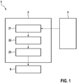
- FIG. 1 shows a schematic block diagram of a sensor system 1 of a vehicle.
- the sensor system 1 comprises at least one sensor 3, which may comprise a camera sensor, a radar sensor, a lidar sensor, an infrared sensor or the like.
- the sensor 3 acquires sensor data at each of a plurality of acquisition times.
- the sensor data may comprise camera images, radar images, and the like.
- the sensor system 1 further comprises a device 2 for predicting a trajectory of a traffic participant.
- the traffic participant can be the vehicle itself.
- the traffic participant can also be a further vehicle, a pedestrian, cyclist, or the like. It is also possible to predict both the trajectory of the vehicle itself and of other traffic participants.
- the device 2 comprises an interface 21 coupled to the at least one sensor 3 and adapted to receive sensor data acquired by the at least one sensor 3.
- the device 2 further comprises a memory 22 which stores the received sensor data.
- the memory 22 may comprise a volatile or non-volatile data memory, e.g. a solid-state disk, memory card or the like.
- a computer 23 of the device 2 is connected to the memory 22 and has access to the memory 22.
- the computer 23 may comprise at least one of a central processing unit (CPU), graphics processing unit (GPU), microcontroller, integrated circuit (IC), application-specific integrated circuit (ASIC), or the like.
- the computer 23 analyzes the received sensor data to compute values of motion parameters of the traffic participant for each acquisition time. For instance, the computer 23 may determine values for a position, a velocity and an acceleration of the traffic participant for each acquisition time. The values of the motion parameters of the traffic participants are input for a stochastic regression algorithm. The position, velocity and acceleration may be given as two-dimensional vectors relative to a driving plane or can be three-dimensional values.
- the stochastic regression algorithm is based on a stochastic process, i.e. a collection of random variables indexed by time, the random variables corresponding to the motion parameters of the traffic participant.
- the stochastic regression algorithm is a Gaussian regression algorithm, also known as kriging.
- the Gaussian regression algorithm serves as a non-linear multivariate interpolation algorithm.
- the computer 23 uses the stochastic regression algorithm to compute predicted values of motion parameters of the traffic participant.
- the computer 23 may determine the predicted acceleration of the traffic participant for a plurality of time points in the future or as a continuous function of time.
- the components of the acceleration vector can be modeled as Gaussian stochastic processes, making it possible to handle prediction in an optimal, mathematically correct way.
- the method automatically adapts to the current situation by considering only the most recent measurements and estimating the probability distribution of the acceleration.
- the computer 23 further integrates the distributions of the predicted acceleration of the traffic participant, using the determined position and velocity of the traffic participant at the acquisition times as initial values to determine integration constants.
- the computer 23 outputs the predicted trajectory, e.g. to a driver assistance system 6.
- the computer 23 may further provide an uncertainty of the predicted trajectory of the traffic participant using the stochastic regression algorithm.
- the computer 23 may use the uncertainty, i.e. the error estimate, together with the predicted trajectory to calculate the probability of an accident for the vehicle with the traffic participant.
- the computer 23 may also estimate a road topology of a road the vehicle is driving on, using the uncertainty and the predicted trajectory.
- the described prediction of the trajectory of the traffic participant can be carried out for a plurality of traffic participants in a surrounding of the vehicle. All trajectories can be predicted simultaneously by taking possible interactions between the traffic participants into account. For instance, the possible trajectories of the traffic participants can be reduced by excluding trajectories that would result in accidents between traffic participants and other traffic participants or the vehicle.
- the driver assistance system 6 may control the vehicle based on the predicted trajectory of the further traffic participant.
- the driver assistance system 6 may be configured to carry out autonomous driving functions by controlling an acceleration, turn rate and the like of the vehicle.
- the device may also predict the trajectory of the vehicle itself.
- the sensor 3 may comprise an inertial sensor for measuring the acceleration of the vehicle.
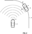
- Figure 2 shows an exemplary traffic scenario for illustrating the method for predicting a trajectory T of a traffic participant 5 in the surrounding of a vehicle 4.
- the computer 23 Based on sensor data acquired by a sensor 3 of the vehicle 4, the computer 23 determines position x, velocity v and acceleration a of the traffic participant 5 for each acquisition time.
- the trajectory T the traffic participant 5 is driving on is predicted for future time points.
- Figure 3 shows a schematic flow diagram of a method for predicting a trajectory of a traffic participant.
- a first method step S1 at least one sensor 3 of the vehicle 4 acquires sensor data for each of a plurality of acquisition times.
- An interface 21 receives the acquired sensor data.
- a computer 23 determines, based on the received sensor data, values of at least one motion parameter of the traffic participant for each acquisition time.
- the motion parameters may comprise a position, a velocity and an acceleration of the traffic participant.
- the motion parameters may also comprise a turn rate or the like.
- the trajectory of the traffic participant is predicted.
- the method step S3 comprises a first sub-step S31, wherein the computer determines a predicted acceleration of the traffic participant using a stochastic regression algorithm.
- the computer 23 integrates the predicted acceleration to compute the predicted trajectory of the traffic participant 5.
- Figure 4 relates to the quality of the estimated trajectory.
- Figure 4 shows an exemplary average of the square root of the squared error of estimation (E) in meters (m).
- the difference between the estimated trajectory from the actual trajectory (based on real measurements) is illustrated at some characteristic distances (d) in meters (m).
- the error of estimation is displayed for a reference model (M1) and for the method according to the invention (M2).
- the reference model is a constant-turn-rate model, i.e. assumes that the turn rate does not change within the time span under consideration. It can be seen that at short ranges at about 10 meters ahead of the vehicle, the error of the estimation decreases by about 75 percent as compared to the reference model M1. At middle ranges of about 50 meters ahead of the vehicle, the error of the estimation still decreases by about 50 percent. Also at larger distances of about 100 meters the difference is significant.
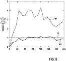
- Figure 5 shows an exemplary error estimation of a standard deviation of a ratio of a real error and an estimated standard deviation of predictions for the method according to the invention (M2) and the constant-turn-rate model (M1).
- the functions depend on distances (d) in meters (m).
- a target line A is shown, corresponding to a constant value of 1.
- Figure 5 relates to a quality of the error estimation. Error estimation is a statistical property and can only be verified based on statistical quantities.
- the evaluation of the error estimation is a complex task, as both the real error and the estimated error are changing with elapsed time and distance.
- a real error of the i-th prediction is denoted by ⁇ _i and the estimated standard deviation of the i-th prediction is denoted by ⁇ _i.
- the reference model M1 is too optimistic about its prediction, the errors it really makes being much larger than it assumes. Based on the new approach, the error estimation is reliable as it is close to the target of 1.
- the reliability of the error estimation makes it possible to use the approach in combination with other models.
- the approach is neither too optimistic nor too pessimistic about its own uncertainty. As a result, during the fusion of the approach with other trajectory estimation methods, the correct trajectory prediction uncertainty will not interfere in the trajectory fusion algorithms.
Landscapes
- Engineering & Computer Science (AREA)
- Physics & Mathematics (AREA)
- General Physics & Mathematics (AREA)
- Analytical Chemistry (AREA)
- Chemical & Material Sciences (AREA)
- Remote Sensing (AREA)
- Radar, Positioning & Navigation (AREA)
- Business, Economics & Management (AREA)
- Theoretical Computer Science (AREA)
- Data Mining & Analysis (AREA)
- Transportation (AREA)
- Mechanical Engineering (AREA)
- Automation & Control Theory (AREA)
- Electromagnetism (AREA)
- Human Resources & Organizations (AREA)
- Tourism & Hospitality (AREA)
- Strategic Management (AREA)
- Economics (AREA)
- Pure & Applied Mathematics (AREA)
- Computational Mathematics (AREA)
- Mathematical Analysis (AREA)
- Mathematical Optimization (AREA)
- Mathematical Physics (AREA)
- Bioinformatics & Computational Biology (AREA)
- Life Sciences & Earth Sciences (AREA)
- Evolutionary Biology (AREA)
- General Engineering & Computer Science (AREA)
- Operations Research (AREA)
- Bioinformatics & Cheminformatics (AREA)
- Development Economics (AREA)
- Computer Networks & Wireless Communication (AREA)
- Marketing (AREA)
- Human Computer Interaction (AREA)
- General Business, Economics & Management (AREA)
- Databases & Information Systems (AREA)
- Probability & Statistics with Applications (AREA)
- Algebra (AREA)
- Software Systems (AREA)
- Game Theory and Decision Science (AREA)
- Evolutionary Computation (AREA)
Abstract
Description
- The present invention relates to a method and a device for predicting a trajectory of a traffic participant. The invention further relates to a sensor system.
- Trajectory prediction is an important part of modern driver assistance systems and essential for autonomous driving. Chief applications are lane estimation, collision avoidance, lane departure prevention and the like.
- Trajectory prediction is typically carried out under the assumption that some dynamic parameters are constant. For example, the assumption can be that the velocity stays constant during the time interval of the prediction. Further, a constant acceleration can be assumed, i.e. the acceleration of the vehicle is taken to be constant for the time of interest. Constant turn rate models predict the future trajectory of vehicles by assuming that the turn rate or yaw rate of the vehicles are constant.
-
DE 10 2013 005 362 A1 discloses a method for analyzing traffic conditions. Future movement behavior is predicted in the form of movement trajectories. -
DE 10 2018 210 065 A1 relates to a device for controlling the velocity of a vehicle. Acceleration of a vehicle is controlled based on a risk function. -
EP 3 518 001 A1 - Further models may decrease the noise of measurements, e.g. using Kalman filters, or dynamically select a seemingly most suitable model, e.g. using switched linear dynamic systems.
- The present invention provides a method and a device for predicting a trajectory of a traffic participant, and a sensor system as recited in the independent claims. Preferred embodiments are set out in the dependent claims.
- According to a first aspect, the invention provides a computer-implemented method for predicting a trajectory of a traffic participant. Sensor data acquired by at least one vehicle sensor at a plurality of acquisition times is received. Based on the received sensor data, values of at least one motion parameter of the traffic participant are determined for each acquisition time. The trajectory of the traffic participant is predicted using a stochastic regression algorithm which receives the measured values of the at least one motion parameter of the traffic participant as an input.
- According to a second aspect, the invention provides a device for predicting a trajectory of a traffic participant, comprising an interface, a memory and a computer. The interface is adapted to receive sensor data acquired by at least one vehicle sensor at a plurality of acquisition times. The memory is adapted to store the received sensor data. The computer is adapted to determine, based on the received sensor data, values of at least one motion parameter of the traffic participant for each acquisition time, and to predict the trajectory of the traffic participant using a stochastic regression algorithm which receives the determined values of the at least one motion parameter of the traffic participant as an input.
- According to a third aspect, the invention provides a sensor system for a vehicle, comprising at least one sensor adapted to acquire sensor data, and a device for predicting a trajectory of the traffic participant according to the invention.
- The assumption that the currently measured dynamical parameters remain constant in the future generally does not hold. Further, the error estimation in models which take dynamical parameters to be constant is based on heuristics rather than rigorous mathematics. Therefore, it is hard to prove that the error estimation of these models is reliable.
- An idea of the invention is to apply a stochastic regression algorithm which can provide an optimal trajectory estimation without the assumption that any of the motion parameters of the vehicle are constant. In contrast to models using constant parameters during prediction, a stochastic regression algorithm exploits only the stationarity of the probability distribution of the motion parameters of the traffic participant and the time interval of interest.
- According to an embodiment of the method for predicting the trajectory of the traffic participant, the traffic participant is a vehicle and the vehicle sensors are vehicle sensors of the vehicle. According to this embodiment, the trajectory of the vehicle itself is predicted.
- According to a further embodiment of the method for predicting the trajectory of the traffic participant, the traffic participant is a vehicle, pedestrian, cyclist or the like, other than the vehicle having the vehicle sensors. According to this embodiment, the trajectories of other traffic participants are predicted.
- According to a further embodiment of the method for predicting the trajectory of the traffic participant, predicting the trajectory of the traffic participant comprises the step of computing a predicted acceleration of the traffic participant using the stochastic regression algorithm, and integrating the predicted acceleration of the traffic participant to compute the predicted trajectory of the traffic participant.
- According to a further embodiment of the method for predicting the trajectory of the traffic participant, the stochastic regression algorithm is a Gaussian regression algorithm.
- According to a further embodiment of the method for predicting the trajectory of the traffic participant, the determined values of the at least one motion parameter of the traffic participant comprise values for a position of the traffic participant, a velocity of the traffic participant and an acceleration of the traffic participant for each acquisition time.
- According to a further embodiment of the method for predicting the trajectory of the traffic participant, an uncertainty of the predicted trajectory of the traffic participant is computed using the stochastic regression algorithm. An advantage of a stochastic regression algorithm is that not only the predicted trajectory itself but also an accurate and mathematically correct uncertainty computation, i.e. error estimation, can be provided. The method can therefore provide a grade of determinism. The higher the correlation between two subsequent measurements, the more the earlier measurement influences the later. In other words, the dynamical properties at a specific time in the future are influenced by the measurements in the past. In general, the greater the time difference between them, the less the influence is. Gaussian regression algorithms can quantify the determinism between past measurements and the future estimation.
- According to a further embodiment of the method for predicting the trajectory of the traffic participant, the predicted trajectory of the traffic participant and the uncertainty of the predicted trajectory of the traffic participant are used to calculate the probability of an accident for the traffic participant. In case an accident is predicted with a high probability, an automated emergency brake can be triggered.
- According to a further embodiment of the method for predicting the trajectory of the traffic participant, the predicted trajectory and the uncertainty of the predicted trajectory are used to estimate a road topology of a road the traffic participant is driving on. For example, the road topology can be estimated beyond the line of sight of the vehicle with the at least one vehicle sensor. The predicted trajectories of other traffic participants can be used to estimate the traffic environment beyond turns, buildings and the like.
- According to a further embodiment of the method for predicting the trajectory of the traffic participant, the method is carried out for a plurality of traffic participants. The plurality of traffic participants may include the vehicle having the at least one vehicle sensor. The trajectories of the plurality of traffic participants are predicted, wherein possible interactions between the plurality of traffic participants are taken into account for predicting the trajectory of the plurality of traffic participants. For example, it may be assumed that accidents between the traffic participants are to be avoided by giving an accident a low priority. The possible trajectories of the plurality of traffic participants can thereby be reduced by excluding trajectories that would result in an accident. Accordingly, the driving tasks of the traffic participants are recognized ahead of time.
- According to a further embodiment of the method for predicting the trajectory of the traffic participant, the sensor data comprises at least one of camera data or radar data.
-
- Figure 1
- shows a schematic block diagram of a sensor system of a vehicle according to an embodiment of the invention;
- Figure 2
- shows an exemplary traffic scenario for illustrating a method for predicting a trajectory of a traffic participant in the surrounding of a vehicle;
- Figure 3
- shows a schematic flow diagram of a method for predicting a trajectory of a traffic participant according to an embodiment of the invention;
- Figure 4
- shows an exemplary average error of estimation in meters for the method according to
Figure 3 and a constant-turn-rate model; and - Figure 5
- shows an exemplary error estimation of a standard deviation of a ratio of a real error and an estimated standard deviation of predictions for the method according to
Figure 3 and a constantturn-rate model. - In the figures, like reference numerals designate corresponding similar parts.
-
Figure 1 shows a schematic block diagram of asensor system 1 of a vehicle. Thesensor system 1 comprises at least onesensor 3, which may comprise a camera sensor, a radar sensor, a lidar sensor, an infrared sensor or the like. Thesensor 3 acquires sensor data at each of a plurality of acquisition times. The sensor data may comprise camera images, radar images, and the like. - The
sensor system 1 further comprises adevice 2 for predicting a trajectory of a traffic participant. The traffic participant can be the vehicle itself. The traffic participant can also be a further vehicle, a pedestrian, cyclist, or the like. It is also possible to predict both the trajectory of the vehicle itself and of other traffic participants. Thedevice 2 comprises aninterface 21 coupled to the at least onesensor 3 and adapted to receive sensor data acquired by the at least onesensor 3. Thedevice 2 further comprises amemory 22 which stores the received sensor data. Thememory 22 may comprise a volatile or non-volatile data memory, e.g. a solid-state disk, memory card or the like. - A
computer 23 of thedevice 2 is connected to thememory 22 and has access to thememory 22. Thecomputer 23 may comprise at least one of a central processing unit (CPU), graphics processing unit (GPU), microcontroller, integrated circuit (IC), application-specific integrated circuit (ASIC), or the like. - The
computer 23 analyzes the received sensor data to compute values of motion parameters of the traffic participant for each acquisition time. For instance, thecomputer 23 may determine values for a position, a velocity and an acceleration of the traffic participant for each acquisition time. The values of the motion parameters of the traffic participants are input for a stochastic regression algorithm. The position, velocity and acceleration may be given as two-dimensional vectors relative to a driving plane or can be three-dimensional values. - The stochastic regression algorithm is based on a stochastic process, i.e. a collection of random variables indexed by time, the random variables corresponding to the motion parameters of the traffic participant. Preferably, the stochastic regression algorithm is a Gaussian regression algorithm, also known as kriging. The Gaussian regression algorithm serves as a non-linear multivariate interpolation algorithm. Using the stochastic regression algorithm, the
computer 23 computes predicted values of motion parameters of the traffic participant. In particular, thecomputer 23 may determine the predicted acceleration of the traffic participant for a plurality of time points in the future or as a continuous function of time. The components of the acceleration vector can be modeled as Gaussian stochastic processes, making it possible to handle prediction in an optimal, mathematically correct way. The method automatically adapts to the current situation by considering only the most recent measurements and estimating the probability distribution of the acceleration. - The
computer 23 further integrates the distributions of the predicted acceleration of the traffic participant, using the determined position and velocity of the traffic participant at the acquisition times as initial values to determine integration constants. Thecomputer 23 outputs the predicted trajectory, e.g. to adriver assistance system 6. - The
computer 23 may further provide an uncertainty of the predicted trajectory of the traffic participant using the stochastic regression algorithm. Thecomputer 23 may use the uncertainty, i.e. the error estimate, together with the predicted trajectory to calculate the probability of an accident for the vehicle with the traffic participant. Thecomputer 23 may also estimate a road topology of a road the vehicle is driving on, using the uncertainty and the predicted trajectory. - The described prediction of the trajectory of the traffic participant can be carried out for a plurality of traffic participants in a surrounding of the vehicle. All trajectories can be predicted simultaneously by taking possible interactions between the traffic participants into account. For instance, the possible trajectories of the traffic participants can be reduced by excluding trajectories that would result in accidents between traffic participants and other traffic participants or the vehicle.
- The
driver assistance system 6 may control the vehicle based on the predicted trajectory of the further traffic participant. Thedriver assistance system 6 may be configured to carry out autonomous driving functions by controlling an acceleration, turn rate and the like of the vehicle. - Instead of predicting trajectories of further traffic participants, the device may also predict the trajectory of the vehicle itself. In this case, the
sensor 3 may comprise an inertial sensor for measuring the acceleration of the vehicle. -
Figure 2 shows an exemplary traffic scenario for illustrating the method for predicting a trajectory T of atraffic participant 5 in the surrounding of avehicle 4. Based on sensor data acquired by asensor 3 of thevehicle 4, thecomputer 23 determines position x, velocity v and acceleration a of thetraffic participant 5 for each acquisition time. The trajectory T thetraffic participant 5 is driving on is predicted for future time points. -
Figure 3 shows a schematic flow diagram of a method for predicting a trajectory of a traffic participant. - In a first method step S1, at least one
sensor 3 of thevehicle 4 acquires sensor data for each of a plurality of acquisition times. Aninterface 21 receives the acquired sensor data. - In a second method step S2, a
computer 23 determines, based on the received sensor data, values of at least one motion parameter of the traffic participant for each acquisition time. The motion parameters may comprise a position, a velocity and an acceleration of the traffic participant. The motion parameters may also comprise a turn rate or the like. - In a further method step S3, the trajectory of the traffic participant is predicted. The method step S3 comprises a first sub-step S31, wherein the computer determines a predicted acceleration of the traffic participant using a stochastic regression algorithm. In a further sub-step S32, the
computer 23 integrates the predicted acceleration to compute the predicted trajectory of thetraffic participant 5. -
Figure 4 relates to the quality of the estimated trajectory.Figure 4 shows an exemplary average of the square root of the squared error of estimation (E) in meters (m). The difference between the estimated trajectory from the actual trajectory (based on real measurements) is illustrated at some characteristic distances (d) in meters (m). The error of estimation is displayed for a reference model (M1) and for the method according to the invention (M2). The reference model is a constant-turn-rate model, i.e. assumes that the turn rate does not change within the time span under consideration. It can be seen that at short ranges at about 10 meters ahead of the vehicle, the error of the estimation decreases by about 75 percent as compared to the reference model M1. At middle ranges of about 50 meters ahead of the vehicle, the error of the estimation still decreases by about 50 percent. Also at larger distances of about 100 meters the difference is significant. -
Figure 5 shows an exemplary error estimation of a standard deviation of a ratio of a real error and an estimated standard deviation of predictions for the method according to the invention (M2) and the constant-turn-rate model (M1). The functions depend on distances (d) in meters (m). A target line A is shown, corresponding to a constant value of 1.Figure 5 relates to a quality of the error estimation. Error estimation is a statistical property and can only be verified based on statistical quantities. The evaluation of the error estimation is a complex task, as both the real error and the estimated error are changing with elapsed time and distance. A real error of the i-th prediction is denoted by ε_i and the estimated standard deviation of the i-th prediction is denoted by σ_i. Multiple samples of pairs of real errors ε_i and estimated errors σ_i are examined. If the values of the estimated errors σ_i are good estimations for the values of the real errors ε_i, the standard deviation of ε_i/ σ_i, i.e. Stddev(ε_i/ σ_i), stays close to 1. This follows from the fact that each of the ε_i samples will be normalized with the σ_i estimated error. Thus, if the estimated error is statistically less than the real error, i.e. the model is too optimistic, the standard deviation of the ratio will be greater than 1. If the estimated error on the other hand is statistically greater than the real error, i.e. the model is too pessimistic, the standard deviation of the ratio will be smaller than 1. - As can be seen from
figure 5 , the reference model M1 is too optimistic about its prediction, the errors it really makes being much larger than it assumes. Based on the new approach, the error estimation is reliable as it is close to the target of 1. - The reliability of the error estimation makes it possible to use the approach in combination with other models. The approach is neither too optimistic nor too pessimistic about its own uncertainty. As a result, during the fusion of the approach with other trajectory estimation methods, the correct trajectory prediction uncertainty will not interfere in the trajectory fusion algorithms.
Claims (10)
- A computer-implemented method for predicting a trajectory (T) of a traffic participant (4, 5), comprising the steps:receiving (S1) sensor data acquired by at least one vehicle sensor (3) at a plurality of acquisition times;determining (S2), based on the received sensor data, values of at least one motion parameter of the traffic participant (4, 5) for each acquisition time; andpredicting (S3) the trajectory (T) of the traffic participant (4, 5) using a stochastic regression algorithm which receives the determined values of the at least one motion parameter of the traffic participant (4, 5) as an input.
- The method according to claim 1, wherein predicting the trajectory (T) of the traffic participant (4, 5) comprises the step of computing (S31) a predicted acceleration of the traffic participant (4, 5) using the stochastic regression algorithm, and integrating (S32) the predicted acceleration to compute the predicted trajectory (T) of the traffic participant (4, 5).
- The method according to claim 1 or 2, wherein the stochastic regression algorithm is a Gaussian regression algorithm.
- The method according to any of the preceding claims, wherein the determined values of the at least one motion parameter of the traffic participant (4, 5) comprise values for a position (x) of the traffic participant (4, 5), a velocity (v) of the traffic participant (4, 5) and an acceleration (a) of the traffic participant (4, 5) for each acquisition time.
- The method according to any of the preceding claims, wherein an uncertainty of the predicted trajectory (T) of the traffic participant (4, 5) is computed using the stochastic regression algorithm.
- The method according to claim 5, wherein the predicted trajectory (T) of the traffic participant (4, 5) and the uncertainty of the predicted trajectory (T) of the traffic participant (4, 5) are used to calculate the probability of an accident and/or estimate a road topology.
- The method according to any of the preceding claims, wherein the trajectories of a plurality of traffic participants (5) are predicted, wherein possible interactions between the plurality of traffic participants (5) are taken into account for predicting the trajectory (T) of the plurality of traffic participants (5).
- The method according to any of the preceding claims, wherein the sensor data comprises at least one of camera data or radar data.
- A device (2) for predicting a trajectory (T) of a traffic participant (4, 5), comprising:an interface (21) adapted to receive sensor data acquired by at least one vehicle sensor (3) at a plurality of acquisition times;a memory (22) adapted to store the received sensor data;a computer (23) adapted to determine, based on the received sensor data, values of at least one motion parameter of the traffic participant (4, 5) for each acquisition time, and to predict the trajectory (T) of the traffic participant (4, 5) using a stochastic regression algorithm which receives the determined values of the at least one motion parameter of the traffic participant (4, 5) as an input.
- A sensor system (1) for a vehicle (4), comprising:at least one sensor (3) adapted to acquire sensor data; anda device (2) according to claim 9 for predicting a trajectory (T) of a traffic participant (4, 5) based on the acquired sensor data.
Priority Applications (4)
| Application Number | Priority Date | Filing Date | Title |
|---|---|---|---|
| EP20176273.9A EP3916697A1 (en) | 2020-05-25 | 2020-05-25 | Method and device for predicting the trajectory of a traffic participant, and sensor system |
| US17/211,066 US20210366274A1 (en) | 2020-05-25 | 2021-03-24 | Method and device for predicting the trajectory of a traffic participant, and sensor system |
| JP2021086600A JP2021190119A (en) | 2020-05-25 | 2021-05-24 | Method and device for predicting route of traffic participant, and sensor system |
| CN202110571583.3A CN113988353A (en) | 2020-05-25 | 2021-05-25 | Method and device for predicting track of traffic participant and sensor system |
Applications Claiming Priority (1)
| Application Number | Priority Date | Filing Date | Title |
|---|---|---|---|
| EP20176273.9A EP3916697A1 (en) | 2020-05-25 | 2020-05-25 | Method and device for predicting the trajectory of a traffic participant, and sensor system |
Publications (1)
| Publication Number | Publication Date |
|---|---|
| EP3916697A1 true EP3916697A1 (en) | 2021-12-01 |
Family
ID=70847265
Family Applications (1)
| Application Number | Title | Priority Date | Filing Date |
|---|---|---|---|
| EP20176273.9A Ceased EP3916697A1 (en) | 2020-05-25 | 2020-05-25 | Method and device for predicting the trajectory of a traffic participant, and sensor system |
Country Status (4)
| Country | Link |
|---|---|
| US (1) | US20210366274A1 (en) |
| EP (1) | EP3916697A1 (en) |
| JP (1) | JP2021190119A (en) |
| CN (1) | CN113988353A (en) |
Cited By (2)
| Publication number | Priority date | Publication date | Assignee | Title |
|---|---|---|---|---|
| CN113988353A (en) * | 2020-05-25 | 2022-01-28 | 罗伯特·博世有限公司 | Method and device for predicting track of traffic participant and sensor system |
| EP4219258A1 (en) * | 2022-01-28 | 2023-08-02 | Aptiv Technologies Limited | Method, computer system and non-transitory computer readable medium for target selection in the vicinty of a vehicle |
Families Citing this family (5)
| Publication number | Priority date | Publication date | Assignee | Title |
|---|---|---|---|---|
| EP4217987A1 (en) * | 2020-11-24 | 2023-08-02 | Huawei Technologies Co., Ltd. | Estimating accident risk level of road traffic participants |
| EP4270997A1 (en) * | 2022-04-26 | 2023-11-01 | Continental Automotive Technologies GmbH | Method for predicting traffic participant behavior, driving system and vehicle |
| CN116010538A (en) * | 2022-10-12 | 2023-04-25 | 上海滴滴沃芽科技有限公司 | Traffic heat map generation method, device, equipment, storage medium and program product |
| CN115877343B (en) * | 2023-02-02 | 2023-05-05 | 中电信数字城市科技有限公司 | Man-car matching method and device based on radar target tracking and electronic equipment |
| CN120319017B (en) * | 2025-04-01 | 2025-12-05 | 武汉理工大学 | A method for identifying traffic conflicts on a full-length road segment based on collision conditions. |
Citations (7)
| Publication number | Priority date | Publication date | Assignee | Title |
|---|---|---|---|---|
| DE102013005362A1 (en) | 2013-03-28 | 2013-10-10 | Daimler Ag | Method for analyzing traffic conditions between vehicle and road user at e.g. road crossings, involves dynamically determining danger areas based on points of intersection of predicted movement trajectories |
| DE102018210065A1 (en) | 2017-06-22 | 2018-12-27 | Avl List Gmbh | Device and method for the predictive control of the speed of a vehicle |
| US20190072965A1 (en) * | 2017-09-07 | 2019-03-07 | TuSimple | Prediction-based system and method for trajectory planning of autonomous vehicles |
| EP3518001A1 (en) | 2018-01-25 | 2019-07-31 | Aptiv Technologies Limited | Method for increasing the reliability of determining the position of a vehicle on the basis of a plurality of detection points |
| CN110264721A (en) * | 2019-07-01 | 2019-09-20 | 北京理工大学 | A method for predicting vehicle trajectories around urban intersections |
| CN110298122A (en) * | 2019-07-03 | 2019-10-01 | 北京理工大学 | Automatic driving vehicle urban intersection left-hand rotation decision-making technique based on conflict resolution |
| EP3552904A1 (en) * | 2018-04-10 | 2019-10-16 | Bayerische Motoren Werke Aktiengesellschaft | Method, device and computer program product for predicting the development of a traffic scene involving several participants |
Family Cites Families (17)
| Publication number | Priority date | Publication date | Assignee | Title |
|---|---|---|---|---|
| KR101688675B1 (en) * | 2009-05-07 | 2016-12-21 | 콘티넨탈 테베스 아게 운트 코. 오하게 | Method and apparatus for regulating or controlling the driving stability of a vehicle |
| JP5956914B2 (en) * | 2012-11-14 | 2016-07-27 | Kddi株式会社 | Angular velocity measuring device, calibration program and method having calibration function of gyro sensor |
| CN105023445A (en) * | 2014-07-04 | 2015-11-04 | 吴建平 | Regional traffic dynamic regulation-control method and system |
| DE102014219148A1 (en) * | 2014-09-23 | 2016-03-24 | Robert Bosch Gmbh | Method and device for creating a movement model of a road user |
| US9784592B2 (en) * | 2015-07-17 | 2017-10-10 | Honda Motor Co., Ltd. | Turn predictions |
| JP6409744B2 (en) * | 2015-11-06 | 2018-10-24 | 株式会社アドヴィックス | Vehicle travel support device |
| DE102016215287A1 (en) * | 2016-08-16 | 2018-02-22 | Volkswagen Aktiengesellschaft | Method for determining a maximum possible driving speed for cornering a motor vehicle, control device and motor vehicle |
| US10345815B2 (en) * | 2016-09-14 | 2019-07-09 | Qualcomm Incorporated | Motion planning and intention prediction for autonomous driving in highway scenarios via graphical model-based factorization |
| ES2866945T3 (en) * | 2017-06-09 | 2021-10-20 | Ptv Planung Transp Verkehr Ag | Computer system and method of predicting the state of a traffic system |
| CN109841088B (en) * | 2017-11-24 | 2021-10-22 | 奥迪股份公司 | Vehicle driving assistance system and method |
| JP7125286B2 (en) * | 2018-06-22 | 2022-08-24 | 本田技研工業株式会社 | Behavior prediction device and automatic driving device |
| US11126186B2 (en) * | 2018-09-15 | 2021-09-21 | Toyota Research Institute, Inc. | Systems and methods for predicting the trajectory of a road agent external to a vehicle |
| US11433922B1 (en) * | 2019-12-20 | 2022-09-06 | Zoox, Inc. | Object uncertainty detection |
| CN111081045A (en) * | 2019-12-31 | 2020-04-28 | 智车优行科技(上海)有限公司 | Attitude trajectory prediction method and electronic equipment |
| EP3855120A1 (en) * | 2020-01-23 | 2021-07-28 | Robert Bosch GmbH | Method for long-term trajectory prediction of traffic participants |
| US11458997B2 (en) * | 2020-03-31 | 2022-10-04 | Uatc, Llc | Autonomous vehicle computing system with processing assurance |
| EP3916697A1 (en) * | 2020-05-25 | 2021-12-01 | Robert Bosch GmbH | Method and device for predicting the trajectory of a traffic participant, and sensor system |
-
2020
- 2020-05-25 EP EP20176273.9A patent/EP3916697A1/en not_active Ceased
-
2021
- 2021-03-24 US US17/211,066 patent/US20210366274A1/en not_active Abandoned
- 2021-05-24 JP JP2021086600A patent/JP2021190119A/en active Pending
- 2021-05-25 CN CN202110571583.3A patent/CN113988353A/en active Pending
Patent Citations (7)
| Publication number | Priority date | Publication date | Assignee | Title |
|---|---|---|---|---|
| DE102013005362A1 (en) | 2013-03-28 | 2013-10-10 | Daimler Ag | Method for analyzing traffic conditions between vehicle and road user at e.g. road crossings, involves dynamically determining danger areas based on points of intersection of predicted movement trajectories |
| DE102018210065A1 (en) | 2017-06-22 | 2018-12-27 | Avl List Gmbh | Device and method for the predictive control of the speed of a vehicle |
| US20190072965A1 (en) * | 2017-09-07 | 2019-03-07 | TuSimple | Prediction-based system and method for trajectory planning of autonomous vehicles |
| EP3518001A1 (en) | 2018-01-25 | 2019-07-31 | Aptiv Technologies Limited | Method for increasing the reliability of determining the position of a vehicle on the basis of a plurality of detection points |
| EP3552904A1 (en) * | 2018-04-10 | 2019-10-16 | Bayerische Motoren Werke Aktiengesellschaft | Method, device and computer program product for predicting the development of a traffic scene involving several participants |
| CN110264721A (en) * | 2019-07-01 | 2019-09-20 | 北京理工大学 | A method for predicting vehicle trajectories around urban intersections |
| CN110298122A (en) * | 2019-07-03 | 2019-10-01 | 北京理工大学 | Automatic driving vehicle urban intersection left-hand rotation decision-making technique based on conflict resolution |
Non-Patent Citations (4)
| Title |
|---|
| GOLI SEPIDEH AFKHAMI ET AL: "Vehicle Trajectory Prediction with Gaussian Process Regression in Connected Vehicle Environment$\star$", 2018 IEEE INTELLIGENT VEHICLES SYMPOSIUM (IV), IEEE, 26 June 2018 (2018-06-26), pages 550 - 555, XP033423494, DOI: 10.1109/IVS.2018.8500614 * |
| LI SHENGHONG ET AL: "Joint Trajectory and Ranging Offset Estimation for Accurate Tracking in NLOS Environments", IEEE TRANSACTIONS ON AEROSPACE AND ELECTRONIC SYSTEMS, IEEE SERVICE CENTER, PISCATAWAY, NJ, US, vol. 56, no. 1, 27 February 2019 (2019-02-27), pages 3 - 14, XP011771327, ISSN: 0018-9251, [retrieved on 20200206], DOI: 10.1109/TAES.2019.2901587 * |
| LIM QUN ET AL: "Gaussian Process Auto Regression for vehicle center coordinates Trajectory Prediction", TENCON 2019 - 2019 IEEE REGION 10 CONFERENCE (TENCON), IEEE, 17 October 2019 (2019-10-17), pages 25 - 30, XP033672880, DOI: 10.1109/TENCON.2019.8929719 * |
| PATTERSON ANDREW ET AL: "Intent-Aware Probabilistic Trajectory Estimation for Collision Prediction with Uncertainty Quantification", 2019 IEEE 58TH CONFERENCE ON DECISION AND CONTROL (CDC), IEEE, 11 December 2019 (2019-12-11), pages 3827 - 3832, XP033735924, DOI: 10.1109/CDC40024.2019.9029215 * |
Cited By (4)
| Publication number | Priority date | Publication date | Assignee | Title |
|---|---|---|---|---|
| CN113988353A (en) * | 2020-05-25 | 2022-01-28 | 罗伯特·博世有限公司 | Method and device for predicting track of traffic participant and sensor system |
| EP4219258A1 (en) * | 2022-01-28 | 2023-08-02 | Aptiv Technologies Limited | Method, computer system and non-transitory computer readable medium for target selection in the vicinty of a vehicle |
| EP4219259A1 (en) * | 2022-01-28 | 2023-08-02 | Aptiv Technologies Limited | Method, computer system and non-transitory computer readable medium for target selection in the vicinity of a vehicle |
| US12365365B2 (en) | 2022-01-28 | 2025-07-22 | Aptiv Technologies AG | Method, computer system and non-transitory computer readable medium for target selection in the vicinity of a vehicle |
Also Published As
| Publication number | Publication date |
|---|---|
| CN113988353A (en) | 2022-01-28 |
| US20210366274A1 (en) | 2021-11-25 |
| JP2021190119A (en) | 2021-12-13 |
Similar Documents
| Publication | Publication Date | Title |
|---|---|---|
| US20210366274A1 (en) | Method and device for predicting the trajectory of a traffic participant, and sensor system | |
| US7460951B2 (en) | System and method of target tracking using sensor fusion | |
| EP3106836B1 (en) | A unit and method for adjusting a road boundary | |
| US9779624B2 (en) | Method and system of driving assistance for collision avoidance | |
| US7340380B2 (en) | Method and device for the exchange and processing of data into fusion data | |
| JP6256531B2 (en) | Object recognition processing device, object recognition processing method, and automatic driving system | |
| US20150274161A1 (en) | Method for operating a driver assistance system of a vehicle | |
| US20100076684A1 (en) | Probabilistic lane assignment method | |
| Berthelot et al. | Handling uncertainties in criticality assessment | |
| JP7089832B2 (en) | State estimator | |
| KR20220001498A (en) | Method and system for predicting a trajectory of a target vehicle in an environment of a vehicle | |
| US11458966B2 (en) | Method and device of determining kinematics of a target | |
| JP2021162366A (en) | Sensor delay time estimation device | |
| US11807270B2 (en) | State estimator | |
| KR101390776B1 (en) | Localization device, method and robot using fuzzy extended kalman filter algorithm | |
| KR102261155B1 (en) | Method and apparatus for controlling a vehicle using two virtual sensors | |
| CN119089379B (en) | Automatic driving method and system based on multi-sensor fusion deployment | |
| Ghahroudi et al. | Multisensor data fusion strategies for advanced driver assistance systems | |
| JP7120170B2 (en) | Lane estimation device | |
| CN117471483A (en) | Multi-sensor fusion vehicle distance calculation method and system | |
| EP3846073A1 (en) | Systems and methods for providing a representation of lanes on a roadway | |
| TWI646306B (en) | Method for analyzing error and existence probability of multi-sensor fusion of obstacle detection | |
| CN119805434B (en) | Methods and apparatus for tracking mobile targets, storage media and electronic equipment | |
| CN119421833A (en) | Convergence time estimates and adjustments based on convergence time estimates | |
| Xu et al. | Perception planning in mobile robot navigation |
Legal Events
| Date | Code | Title | Description |
|---|---|---|---|
| PUAI | Public reference made under article 153(3) epc to a published international application that has entered the european phase |
Free format text: ORIGINAL CODE: 0009012 |
|
| STAA | Information on the status of an ep patent application or granted ep patent |
Free format text: STATUS: THE APPLICATION HAS BEEN PUBLISHED |
|
| AK | Designated contracting states |
Kind code of ref document: A1 Designated state(s): AL AT BE BG CH CY CZ DE DK EE ES FI FR GB GR HR HU IE IS IT LI LT LU LV MC MK MT NL NO PL PT RO RS SE SI SK SM TR |
|
| B565 | Issuance of search results under rule 164(2) epc |
Effective date: 20201126 |
|
| STAA | Information on the status of an ep patent application or granted ep patent |
Free format text: STATUS: REQUEST FOR EXAMINATION WAS MADE |
|
| 17P | Request for examination filed |
Effective date: 20220601 |
|
| RBV | Designated contracting states (corrected) |
Designated state(s): AL AT BE BG CH CY CZ DE DK EE ES FI FR GB GR HR HU IE IS IT LI LT LU LV MC MK MT NL NO PL PT RO RS SE SI SK SM TR |
|
| STAA | Information on the status of an ep patent application or granted ep patent |
Free format text: STATUS: EXAMINATION IS IN PROGRESS |
|
| 17Q | First examination report despatched |
Effective date: 20230720 |
|
| STAA | Information on the status of an ep patent application or granted ep patent |
Free format text: STATUS: THE APPLICATION HAS BEEN REFUSED |
|
| 18R | Application refused |
Effective date: 20240724 |