EP3916672A1 - System and method for examining objects for errors - Google Patents
System and method for examining objects for errors Download PDFInfo
- Publication number
- EP3916672A1 EP3916672A1 EP20177525.1A EP20177525A EP3916672A1 EP 3916672 A1 EP3916672 A1 EP 3916672A1 EP 20177525 A EP20177525 A EP 20177525A EP 3916672 A1 EP3916672 A1 EP 3916672A1
- Authority
- EP
- European Patent Office
- Prior art keywords
- recognition
- designed
- error
- result
- module
- Prior art date
- Legal status (The legal status is an assumption and is not a legal conclusion. Google has not performed a legal analysis and makes no representation as to the accuracy of the status listed.)
- Pending
Links
Images


Classifications
-
- G—PHYSICS
- G06—COMPUTING OR CALCULATING; COUNTING
- G06T—IMAGE DATA PROCESSING OR GENERATION, IN GENERAL
- G06T7/00—Image analysis
- G06T7/0002—Inspection of images, e.g. flaw detection
- G06T7/0004—Industrial image inspection
- G06T7/0006—Industrial image inspection using a design-rule based approach
-
- G—PHYSICS
- G06—COMPUTING OR CALCULATING; COUNTING
- G06T—IMAGE DATA PROCESSING OR GENERATION, IN GENERAL
- G06T7/00—Image analysis
- G06T7/0002—Inspection of images, e.g. flaw detection
- G06T7/0004—Industrial image inspection
-
- G—PHYSICS
- G06—COMPUTING OR CALCULATING; COUNTING
- G06T—IMAGE DATA PROCESSING OR GENERATION, IN GENERAL
- G06T7/00—Image analysis
- G06T7/70—Determining position or orientation of objects or cameras
- G06T7/73—Determining position or orientation of objects or cameras using feature-based methods
- G06T7/74—Determining position or orientation of objects or cameras using feature-based methods involving reference images or patches
-
- B—PERFORMING OPERATIONS; TRANSPORTING
- B64—AIRCRAFT; AVIATION; COSMONAUTICS
- B64U—UNMANNED AERIAL VEHICLES [UAV]; EQUIPMENT THEREFOR
- B64U2101/00—UAVs specially adapted for particular uses or applications
- B64U2101/30—UAVs specially adapted for particular uses or applications for imaging, photography or videography
-
- G—PHYSICS
- G06—COMPUTING OR CALCULATING; COUNTING
- G06T—IMAGE DATA PROCESSING OR GENERATION, IN GENERAL
- G06T2207/00—Indexing scheme for image analysis or image enhancement
- G06T2207/10—Image acquisition modality
- G06T2207/10032—Satellite or aerial image; Remote sensing
-
- G—PHYSICS
- G06—COMPUTING OR CALCULATING; COUNTING
- G06T—IMAGE DATA PROCESSING OR GENERATION, IN GENERAL
- G06T2207/00—Indexing scheme for image analysis or image enhancement
- G06T2207/20—Special algorithmic details
- G06T2207/20081—Training; Learning
-
- G—PHYSICS
- G06—COMPUTING OR CALCULATING; COUNTING
- G06T—IMAGE DATA PROCESSING OR GENERATION, IN GENERAL
- G06T2207/00—Indexing scheme for image analysis or image enhancement
- G06T2207/20—Special algorithmic details
- G06T2207/20084—Artificial neural networks [ANN]
-
- G—PHYSICS
- G06—COMPUTING OR CALCULATING; COUNTING
- G06T—IMAGE DATA PROCESSING OR GENERATION, IN GENERAL
- G06T2207/00—Indexing scheme for image analysis or image enhancement
- G06T2207/30—Subject of image; Context of image processing
- G06T2207/30108—Industrial image inspection
- G06T2207/30132—Masonry; Concrete
-
- G—PHYSICS
- G06—COMPUTING OR CALCULATING; COUNTING
- G06T—IMAGE DATA PROCESSING OR GENERATION, IN GENERAL
- G06T2207/00—Indexing scheme for image analysis or image enhancement
- G06T2207/30—Subject of image; Context of image processing
- G06T2207/30181—Earth observation
- G06T2207/30184—Infrastructure
-
- Y—GENERAL TAGGING OF NEW TECHNOLOGICAL DEVELOPMENTS; GENERAL TAGGING OF CROSS-SECTIONAL TECHNOLOGIES SPANNING OVER SEVERAL SECTIONS OF THE IPC; TECHNICAL SUBJECTS COVERED BY FORMER USPC CROSS-REFERENCE ART COLLECTIONS [XRACs] AND DIGESTS
- Y02—TECHNOLOGIES OR APPLICATIONS FOR MITIGATION OR ADAPTATION AGAINST CLIMATE CHANGE
- Y02B—CLIMATE CHANGE MITIGATION TECHNOLOGIES RELATED TO BUILDINGS, e.g. HOUSING, HOUSE APPLIANCES OR RELATED END-USER APPLICATIONS
- Y02B10/00—Integration of renewable energy sources in buildings
- Y02B10/30—Wind power
Definitions
- the present invention relates to a system and a method for examining objects for errors.
- a technical problem in using machine-learning based recognition methods to detect errors, anomalies and other deviations associated with objects consists in training a machine learning system to recognize the errors as such a system suffers from unexpected/untrained events that can occur.
- a system trained for a given set of errors e.g. a neuronal network
- the complexity of the errors the use of trained networks becomes a challenge if the error detection has to be done with a restricted inspection device.
- the time to train for errors and the amount of data for every erroneous situation requires a lot resources until the neuronal network can be deployed and still untrained errors may not be detected.
- the training of all possible errors is very resource-consuming and may be even impossible.
- One objective of the present invention is to provide an improved system and an improved method for examining an object for errors. This objective is solved by a system and a method for examining an object for errors with the features of the independent claims, respectively. Advantageous embodiments are specified within the dependent claims.
- a system for examining at least one object for errors comprises a monitoring device, a processing module, a capturing device and a recognition module.
- the monitoring device is designed to monitor at least one parameter.
- a specified range of the parameter defines a context within which a result of a recognition of at least parts of the object is expected.
- the processing module is designed to prove whether the monitored parameter is within the specified range and in this case to trigger the capturing device.
- the capturing device is designed to capture input data associated with at least parts of the object.
- the recognition module is pre-trained for recognizing at least parts of the object and to perform the recognition of at least parts of the object based on the input data.
- the recognition module is designed to detect an error if a result of the recognition is not corresponding to the expected result.
- the system is based on the idea that in real scenarios a context can be used for the recognition. Also, there is an expected recognition result which is linked to the context. This context is given by the specified range of the parameter.
- performing the recognition within the context enables an efficient detection of errors associated with the object.
- the system can run on edge devices or devices with limited computing capacity.
- the system can be part of a mobile apparatus.
- the monitoring device is designed to monitor a location of the system.
- the recognition module is designed to detect an error if the system is within a specified region of the object and a result of the recognition is not corresponding to the expected result.
- the location of the system represents the parameter.
- the specified region of the object represents the context.
- the object is only expected to be present, if the system is within the specified region of the object. If the pre-trained recognition module is not able to detect the object or at least parts of the object although the system is within the specified region it is assumed that an error is present associated with the object which represents an unexpected event for the recognition module as it has not been trained for.
- the monitoring device is designed to monitor an orientation of the capturing device.
- the recognition module is designed to detect an error if the capturing device is oriented according to a specified orientation range with respect to the object and a result of the recognition is not corresponding to the expected result.
- the orientation of the capturing device represents the parameter.
- the specified orientation range of the object represents the context.
- the object or at least parts of the object can only be captured, if the capturing device is oriented according to the specified orientation range with respect to the object. If the pre-trained recognition module is not able to detect the object or at least parts of the object although the capturing device is oriented according to the specified orientation range it is assumed that an error is present associated with the object.
- the monitoring device is designed to monitor a time as the parameter.
- the recognition module is designed to detect an error if the recognition module is performing the recognition within a specified time slot representing the context and a result of the recognition is not corresponding to the expected result.
- the object or at least parts of the object can only be captured, if the recognition module is performing the recognition within the specified time slot. If the pre-trained recognition module is not able to detect the object or at least parts of the object although the recognition module is performing the recognition within the specified time slot it is assumed that an error is present associated with the object.
- system comprises a communication module designed to transmit the input data to a controlling station if an error is detected.
- a communication module designed to transmit the input data to a controlling station if an error is detected.
- the system comprises a plurality of error modules.
- Each error module is pre-trained for a recognition of a specific error.
- the system is designed to perform an error recognition by triggering the error modules sequentially.
- the system can be designed to trigger a certain error module which is trained for the recognition of a specific error which is occurring most frequently compared to other known errors, first.
- a certain error module which is trained for the recognition of a specific error which is occurring most frequently compared to other known errors, first.
- the system can be expanded by adding further error modules, e.g. after the appearance of new types of errors.
- a mobile apparatus comprises a system for examining at least one object for errors according to one of above describe embodiments.
- the mobile apparatus is a drone.
- the capturing device is a camera.
- the recognition module is a neuronal network pre-trained for recognizing at least one intact wind turbine based on at least one image captured by the camera.
- the monitoring device is designed to monitor a location of the drone and an orientation of the camera.
- the recognition module is designed to detect an error if the drone is within a specified region of the wind turbine, the camera is oriented according to a specified orientation range with respect to the wind turbine and a result of the recognition is not corresponding to the expected result of at least one intact wind turbine.
- a method for examining at least one object for errors comprises the following steps. At least one parameter is monitored. A specified range of the parameter defines a context within which a result of a recognition of at least parts of the object is expected. It is proved whether the monitored parameter is within the specified range. Input data associated with at least parts of the object are captured if the parameter is within the specified range. A recognition of at least parts of the object is performed based on the input data. An error is detected if a result of the recognition is not corresponding to the expected result.
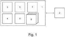
- Fig. 1 schematically shows a system 1 for examining at least one object 2 for errors.
- the object 2 may be any apparatus or any system, e.g. the object 2 can be a wind turbine. However, the object 2 can also e.g. be any industrial production facility and/or industrial product or e.g. a building. There may be different errors associated with the object 2, e.g. mechanical damages and/or other technical failures may occur. An error can also consist in another undesirable condition of the object 2, e.g. an error can consist in a delayed arrival of a product.
- the system 1 can e.g. be part of a mobile apparatus.
- the system can e.g. be part of a vehicle or a drone which can be used for the purpose of the detection of errors associated with the object 2.
- the system 1 may be also part of an immobile apparatus, e.g. a stationary surveillance system.
- the system 1 comprises a monitoring device 3.
- the monitoring device 3 is designed to monitor at least one parameter.
- a specified range of the parameter defines a context within which a result of a recognition of at least parts of the object 2 is expected.
- the context can be used for the recognition as there is an expected recognition result which is linked to the context given by the specified range of the parameter.
- the monitoring device 3 is designed to monitor a location of the system 1.
- the monitoring device 3 can be a positioning and navigation system, e.g. a GPS based system.
- the context is given by a specified region of the object 2, i.e. the object 2 is expected to be present within the specified region.
- the capturing device 4 may also be another sensor.
- the monitoring device 3 is designed to monitor a time.
- the context is given by a specified time slot, e.g. within which a certain event is expected, e.g. the arrival of the object 2. If the object 2 is a wind turbine the context may be given by a time slot within which win conditions allow for proper and efficient operation.
- the monitoring device 3 is designed to monitor an orientation of a capturing device 4 of the system 1.
- the capturing device 4 is designed to capture input data associated with at least parts of the object 2.
- the capturing device 4 can e.g. be a camera designed to provide images and videos of the object 2.
- the system 1 comprises a processing module 5 designed to prove whether the monitored parameter is within the specified range. If this is the case, the processing module 5 is designed to trigger the capturing device 4 to capture the input data associated with the object 2. E.g. the capturing device 4 captures images and/or videos of the object 2.
- the system 1 comprises a recognition module 6.
- the recognition module 6 comprises a machine learning based algorithm, e.g. a neuronal network.
- a machine learning based algorithm e.g. a neuronal network.
- the recognition module 6 is pre-trained for recognizing at least parts of the object 2 and to perform the recognition of at least parts of the object 2 based on the input data captured and provided by the capturing device.
- the input data may be adapted prior to the recognition process.
- an image may be adapted to a neuronal network by scaling the image to a size which is compatible with the neuronal network.
- the recognition module 6 is designed to detect an error based on the input data if a result of the recognition is not corresponding to the expected result.
- the recognition module 6 is designed to detect an error if the system 1 is within a specified region of the object 2 and a result of the recognition is not corresponding to the expected result.
- the recognition module 6 can be designed to detect an error if the capturing device 4 is oriented according to a specified orientation range with respect to the object 2 and a result of the recognition is not corresponding to the expected result.
- the recognition module 6 can be designed to detect an error if the recognition module 6 is performing the recognition within a specified time slot and a result of the recognition is not corresponding to the expected result.
- Performing the recognition within the context enables an efficient detection of errors associated with the object 2. Also, there is no need to train the recognition module for all potential situations and errors which may occur, whereby a training time may be reduced. Furthermore, the necessity to provide training data for a plurality of errors is avoided. As the training of the recognition module 6 is kept simple and smaller than a complex training, the system 1 can run on edge devices or devices with limited computing capacity. Thus, the system 1 can be part of a mobile apparatus.
- the system 1 may also comprise a communication module 7.
- the communication module 1 can be designed to transmit information about detected errors and/or the captured input data to a controlling station for further examination.
- the system 1 can comprise a plurality of error modules 8.
- Each error module comprises a machine learning based algorithm, e.g. a neuronal network, which is pre-trained for a recognition of a specific error.
- the system 1 is designed to perform an error recognition by triggering the error modules 8 sequentially.
- the error modules 8 can be triggered by the processing module 5 after the recognition module 6 has detected an error. If a first error module detects its error type, information about the error can be transmitted to the controlling station, too. If the first error module fails to recognize the error it has been trained for, a second error module is triggered to perform its own error recognition. Thus, an efficient error recognition is enabled.
- Fig. 2 schematically shows method steps 11, 12, 13, 14, 15, 16, 17 of a method 9 for examining at least one object 2 for errors.
- a first method step 11 of the method 9 the at least one parameter is monitored.
- the specified range of the parameter defines the context within which a result of a recognition of at least parts of the object is expected.
- a second method step 12 it is proved whether the monitored parameter is within the specified range.
- the input data associated with at least parts of the object 2 is captured if the parameter is within the specified range.
- the recognition of at least parts of the object 2 is performed based on the input data.
- an error is detected if a result of the recognition is not corresponding to the expected result.
- the method may also comprise a sixth step 16 within which information about detected errors and/or the captured input data are transmitted to a controlling station for further examination.
- a sixth step 16 within which information about detected errors and/or the captured input data are transmitted to a controlling station for further examination.
- an error recognition is performed by triggering the error modules 8 sequentially.
- Fig. 3 schematically shows an exemplary embodiment of the system 1 and an exemplary object 2 which shall be examined for errors.
- the system 1 is part of a drone 10.
- the capturing device 4 is a camera 18 designed to capture images.
- the recognition module 6 which is not shown in Fig. 3 is a neuronal network pre-trained for recognizing at least one intact wind turbine 19 based on at least one image captured by the camera 18.
- the monitoring device 3 is designed to monitor a location of the drone 10 and an orientation of the camera 18.
- the recognition module 6 is designed to detect an error if the drone 10 is within a specified region of the wind turbine 19, the camera 18 is oriented according to a specified orientation range with respect to the wind turbine 19 and a result of the recognition is not corresponding to the expected result of at least one intact wind turbine 19.
- the recognition module 6 can be pre-trained for detecting a wind turbine 19 only if no parts of the wind turbine 19 are missing. If e.g. a blade 20 of the wind turbine 19 is missing, the recognition module 6 is not able to detect the wind turbine 19 as such. In this case, an error can be detected if the recognition is performed within the context given by the specified region of the wind turbine 19 and the specified orientation range with respect to the wind turbine 19 and a result of the recognition is not corresponding to the expected result of at least one intact wind turbine 19.
- the recognition module 6 e.g. may also be pre-trained for recognizing a proper operation of the wind turbine 19 within a specified time slot, e.g. when wind conditions are expected to enable an efficient operation of the wind turbine.
- the system 1 may also comprise error modules 8 not shown in Fig. 3 to perform an error recognition.
- one error module may be pre-trained for recognizing a wind turbine 19 with at least one missing blade 20.
- Another error module 8 may be pre-trained to differentiate wind turbines 19 which are in operation from those which are not, e.g. due to bad wind conditions.
- Information about a detected error can be sent to the controlling station 21 for further examination of the error. Also, information about recognized types of errors may be sent to the controlling station 21 in order to initiate a maintenance.
Landscapes
- Engineering & Computer Science (AREA)
- Computer Vision & Pattern Recognition (AREA)
- Physics & Mathematics (AREA)
- General Physics & Mathematics (AREA)
- Theoretical Computer Science (AREA)
- Quality & Reliability (AREA)
- Image Analysis (AREA)
- Aviation & Aerospace Engineering (AREA)
Abstract
Description
- The present invention relates to a system and a method for examining objects for errors.
- A technical problem in using machine-learning based recognition methods to detect errors, anomalies and other deviations associated with objects consists in training a machine learning system to recognize the errors as such a system suffers from unexpected/untrained events that can occur. A system trained for a given set of errors, e.g. a neuronal network, will therefore fail when unexpected/untrained events occur. With the complexity of the errors the use of trained networks becomes a challenge if the error detection has to be done with a restricted inspection device. Also the time to train for errors and the amount of data for every erroneous situation requires a lot resources until the neuronal network can be deployed and still untrained errors may not be detected. The training of all possible errors is very resource-consuming and may be even impossible.
- One objective of the present invention is to provide an improved system and an improved method for examining an object for errors. This objective is solved by a system and a method for examining an object for errors with the features of the independent claims, respectively. Advantageous embodiments are specified within the dependent claims.
- A system for examining at least one object for errors comprises a monitoring device, a processing module, a capturing device and a recognition module. The monitoring device is designed to monitor at least one parameter. A specified range of the parameter defines a context within which a result of a recognition of at least parts of the object is expected. The processing module is designed to prove whether the monitored parameter is within the specified range and in this case to trigger the capturing device. The capturing device is designed to capture input data associated with at least parts of the object. The recognition module is pre-trained for recognizing at least parts of the object and to perform the recognition of at least parts of the object based on the input data. The recognition module is designed to detect an error if a result of the recognition is not corresponding to the expected result.
- The system is based on the idea that in real scenarios a context can be used for the recognition. Also, there is an expected recognition result which is linked to the context. This context is given by the specified range of the parameter. Advantageously, performing the recognition within the context enables an efficient detection of errors associated with the object.
- Also, there is no need to train the recognition module for all potential situations and errors which may occur. A training time may thus be reduced, advantageously. Furthermore, the necessity to provide training data for a plurality of errors is avoided.
- As the training of the recognition module is kept simple and smaller than a complex training, the system can run on edge devices or devices with limited computing capacity. Thus, the system can be part of a mobile apparatus.
- In an embodiment the monitoring device is designed to monitor a location of the system. The recognition module is designed to detect an error if the system is within a specified region of the object and a result of the recognition is not corresponding to the expected result.
- In this case the location of the system represents the parameter. The specified region of the object represents the context. Advantageously, the object is only expected to be present, if the system is within the specified region of the object. If the pre-trained recognition module is not able to detect the object or at least parts of the object although the system is within the specified region it is assumed that an error is present associated with the object which represents an unexpected event for the recognition module as it has not been trained for.
- In an embodiment the monitoring device is designed to monitor an orientation of the capturing device. The recognition module is designed to detect an error if the capturing device is oriented according to a specified orientation range with respect to the object and a result of the recognition is not corresponding to the expected result.
- In this embodiment case the orientation of the capturing device represents the parameter. The specified orientation range of the object represents the context. Advantageously, the object or at least parts of the object can only be captured, if the capturing device is oriented according to the specified orientation range with respect to the object. If the pre-trained recognition module is not able to detect the object or at least parts of the object although the capturing device is oriented according to the specified orientation range it is assumed that an error is present associated with the object.
- In an embodiment the monitoring device is designed to monitor a time as the parameter. The recognition module is designed to detect an error if the recognition module is performing the recognition within a specified time slot representing the context and a result of the recognition is not corresponding to the expected result.
- Advantageously, the object or at least parts of the object can only be captured, if the recognition module is performing the recognition within the specified time slot. If the pre-trained recognition module is not able to detect the object or at least parts of the object although the recognition module is performing the recognition within the specified time slot it is assumed that an error is present associated with the object.
- In an embodiment the system comprises a communication module designed to transmit the input data to a controlling station if an error is detected. Advantageously, the handling of unexpected situations and errors is deferred.
- In an embodiment the system comprises a plurality of error modules. Each error module is pre-trained for a recognition of a specific error. The system is designed to perform an error recognition by triggering the error modules sequentially.
- Advantageously, the system can be designed to trigger a certain error module which is trained for the recognition of a specific error which is occurring most frequently compared to other known errors, first. Thus, an efficient error recognition is enabled. Also, the system can be expanded by adding further error modules, e.g. after the appearance of new types of errors.
- A mobile apparatus comprises a system for examining at least one object for errors according to one of above describe embodiments.
- In an embodiment the mobile apparatus is a drone. The capturing device is a camera. The recognition module is a neuronal network pre-trained for recognizing at least one intact wind turbine based on at least one image captured by the camera. The monitoring device is designed to monitor a location of the drone and an orientation of the camera. The recognition module is designed to detect an error if the drone is within a specified region of the wind turbine, the camera is oriented according to a specified orientation range with respect to the wind turbine and a result of the recognition is not corresponding to the expected result of at least one intact wind turbine.
- A method for examining at least one object for errors comprises the following steps. At least one parameter is monitored. A specified range of the parameter defines a context within which a result of a recognition of at least parts of the object is expected. It is proved whether the monitored parameter is within the specified range. Input data associated with at least parts of the object are captured if the parameter is within the specified range. A recognition of at least parts of the object is performed based on the input data. An error is detected if a result of the recognition is not corresponding to the expected result.
- In the following, the invention is described in connection with schematic figures, wherein
-
Fig. 1 shows a system for examining at least one object for errors; -
Fig. 2 shows a method for examining at least one object for errors; and -
Fig. 3 shows an exemplary embodiment of the system. -
Fig. 1 schematically shows asystem 1 for examining at least oneobject 2 for errors. - The
object 2 may be any apparatus or any system, e.g. theobject 2 can be a wind turbine. However, theobject 2 can also e.g. be any industrial production facility and/or industrial product or e.g. a building. There may be different errors associated with theobject 2, e.g. mechanical damages and/or other technical failures may occur. An error can also consist in another undesirable condition of theobject 2, e.g. an error can consist in a delayed arrival of a product. - The
system 1 can e.g. be part of a mobile apparatus. The system can e.g. be part of a vehicle or a drone which can be used for the purpose of the detection of errors associated with theobject 2. However, thesystem 1 may be also part of an immobile apparatus, e.g. a stationary surveillance system. - The
system 1 comprises amonitoring device 3. Themonitoring device 3 is designed to monitor at least one parameter. A specified range of the parameter defines a context within which a result of a recognition of at least parts of theobject 2 is expected. The context can be used for the recognition as there is an expected recognition result which is linked to the context given by the specified range of the parameter. - In one embodiment the
monitoring device 3 is designed to monitor a location of thesystem 1. For this, themonitoring device 3 can be a positioning and navigation system, e.g. a GPS based system. In this case, the context is given by a specified region of theobject 2, i.e. theobject 2 is expected to be present within the specified region. However, depending on theobject 2 to be examined thecapturing device 4 may also be another sensor. - Alternatively or additionally, the
monitoring device 3 is designed to monitor a time. In this case, the context is given by a specified time slot, e.g. within which a certain event is expected, e.g. the arrival of theobject 2. If theobject 2 is a wind turbine the context may be given by a time slot within which win conditions allow for proper and efficient operation. - Alternatively or additionally, the
monitoring device 3 is designed to monitor an orientation of acapturing device 4 of thesystem 1. Thecapturing device 4 is designed to capture input data associated with at least parts of theobject 2. Thecapturing device 4 can e.g. be a camera designed to provide images and videos of theobject 2. - The
system 1 comprises aprocessing module 5 designed to prove whether the monitored parameter is within the specified range. If this is the case, theprocessing module 5 is designed to trigger thecapturing device 4 to capture the input data associated with theobject 2. E.g. thecapturing device 4 captures images and/or videos of theobject 2. - For the examination of the
object 2 for errors, thesystem 1 comprises arecognition module 6. Therecognition module 6 comprises a machine learning based algorithm, e.g. a neuronal network. For the purpose of recognition based on images, e.g. deep convolutional neuronal networks may be used. Therecognition module 6 is pre-trained for recognizing at least parts of theobject 2 and to perform the recognition of at least parts of theobject 2 based on the input data captured and provided by the capturing device. The input data may be adapted prior to the recognition process. E.g. an image may be adapted to a neuronal network by scaling the image to a size which is compatible with the neuronal network. - The
recognition module 6 is designed to detect an error based on the input data if a result of the recognition is not corresponding to the expected result. E.g. therecognition module 6 is designed to detect an error if thesystem 1 is within a specified region of theobject 2 and a result of the recognition is not corresponding to the expected result. Also, therecognition module 6 can be designed to detect an error if thecapturing device 4 is oriented according to a specified orientation range with respect to theobject 2 and a result of the recognition is not corresponding to the expected result. Furthermore, therecognition module 6 can be designed to detect an error if therecognition module 6 is performing the recognition within a specified time slot and a result of the recognition is not corresponding to the expected result. - Performing the recognition within the context enables an efficient detection of errors associated with the
object 2. Also, there is no need to train the recognition module for all potential situations and errors which may occur, whereby a training time may be reduced. Furthermore, the necessity to provide training data for a plurality of errors is avoided. As the training of therecognition module 6 is kept simple and smaller than a complex training, thesystem 1 can run on edge devices or devices with limited computing capacity. Thus, thesystem 1 can be part of a mobile apparatus. - Optionally, the
system 1 may also comprise acommunication module 7. Thecommunication module 1 can be designed to transmit information about detected errors and/or the captured input data to a controlling station for further examination. - Additionally, the
system 1 can comprise a plurality oferror modules 8. Each error module comprises a machine learning based algorithm, e.g. a neuronal network, which is pre-trained for a recognition of a specific error. Thesystem 1 is designed to perform an error recognition by triggering theerror modules 8 sequentially. Theerror modules 8 can be triggered by theprocessing module 5 after therecognition module 6 has detected an error. If a first error module detects its error type, information about the error can be transmitted to the controlling station, too. If the first error module fails to recognize the error it has been trained for, a second error module is triggered to perform its own error recognition. Thus, an efficient error recognition is enabled. -
Fig. 2 schematically shows method steps 11, 12, 13, 14, 15, 16, 17 of amethod 9 for examining at least oneobject 2 for errors. - In a
first method step 11 of themethod 9 the at least one parameter is monitored. The specified range of the parameter defines the context within which a result of a recognition of at least parts of the object is expected. In asecond method step 12 it is proved whether the monitored parameter is within the specified range. In athird method step 13 the input data associated with at least parts of theobject 2 is captured if the parameter is within the specified range. In afourth method step 14 the recognition of at least parts of theobject 2 is performed based on the input data. In afifth method step 15 an error is detected if a result of the recognition is not corresponding to the expected result. - Optionally, the method may also comprise a
sixth step 16 within which information about detected errors and/or the captured input data are transmitted to a controlling station for further examination. In another optionalseventh method step 17 an error recognition is performed by triggering theerror modules 8 sequentially. -
Fig. 3 schematically shows an exemplary embodiment of thesystem 1 and anexemplary object 2 which shall be examined for errors. - The
system 1 is part of adrone 10. Thecapturing device 4 is acamera 18 designed to capture images. Therecognition module 6 which is not shown inFig. 3 is a neuronal network pre-trained for recognizing at least oneintact wind turbine 19 based on at least one image captured by thecamera 18. Themonitoring device 3 is designed to monitor a location of thedrone 10 and an orientation of thecamera 18. Therecognition module 6 is designed to detect an error if thedrone 10 is within a specified region of thewind turbine 19, thecamera 18 is oriented according to a specified orientation range with respect to thewind turbine 19 and a result of the recognition is not corresponding to the expected result of at least oneintact wind turbine 19. - E.g. the
recognition module 6 can be pre-trained for detecting awind turbine 19 only if no parts of thewind turbine 19 are missing. If e.g. ablade 20 of thewind turbine 19 is missing, therecognition module 6 is not able to detect thewind turbine 19 as such. In this case, an error can be detected if the recognition is performed within the context given by the specified region of thewind turbine 19 and the specified orientation range with respect to thewind turbine 19 and a result of the recognition is not corresponding to the expected result of at least oneintact wind turbine 19. Therecognition module 6 e.g. may also be pre-trained for recognizing a proper operation of thewind turbine 19 within a specified time slot, e.g. when wind conditions are expected to enable an efficient operation of the wind turbine. - The
system 1 may also compriseerror modules 8 not shown inFig. 3 to perform an error recognition. E.g. one error module may be pre-trained for recognizing awind turbine 19 with at least onemissing blade 20. Anothererror module 8 may be pre-trained to differentiatewind turbines 19 which are in operation from those which are not, e.g. due to bad wind conditions. - Information about a detected error can be sent to the controlling
station 21 for further examination of the error. Also, information about recognized types of errors may be sent to the controllingstation 21 in order to initiate a maintenance. -
- 1
- system for examining at least one object for errors
- 2
- object
- 3
- monitoring device
- 4
- capturing device
- 5
- processing module
- 6
- recognition module
- 7
- communication module
- 8
- error module
- 9
- method for examining at least one object for errors
- 10
- drone
- 11
- first method step
- 12
- second method step
- 13
- third method step
- 14
- fourth method step
- 15
- fifth method step
- 16
- sixth method step
- 17
- seventh method step
- 18
- camera
- 19
- wind turbine
- 20
- blade of the wind turbine
- 21
- controlling station
Claims (9)
- A system (1) for examining at least one object (2) for errors
comprising a monitoring device (3), a processing module (5), a capturing device (4) and a recognition module (6),
wherein the monitoring device (3) is designed to monitor at least one parameter,
wherein a specified range of the parameter defines a context within which a result of a recognition of at least parts of the object (2) is expected,
wherein the processing module (5) is designed to prove whether the monitored parameter is within the specified range and in this case to trigger the capturing device (4),
wherein the capturing device (4) is designed to capture input data associated with at least parts of the object (2),
wherein the recognition module (6) is pre-trained for recognizing at least parts of the object (2) and to perform the recognition of at least parts of the object (2) based on the input data,
wherein the recognition module (6) is designed to detect an error if a result of the recognition is not corresponding to the expected result. - The system (1) according to claim 1,
wherein the monitoring device(3) is designed to monitor a location of the system (1),
wherein the recognition module (6) is designed to detect an error if the system (1) is within a specified region of the object (2) and a result of the recognition is not corresponding to the expected result. - The system (1) according to one of the preceding claims,
wherein the monitoring device (3) is designed to monitor an orientation of the capturing device (4),
wherein the recognition module (6) is designed to detect an error if the capturing device (4) is oriented according to a specified orientation range with respect to the object (2) and a result of the recognition is not corresponding to the expected result. - The system (1) according to one of the preceding claims,
wherein the monitoring device (3) is designed to monitor a time,
wherein the recognition module (6) is designed to detect an error if the recognition module (6) is performing the recognition within a specified time slot and a result of the recognition is not corresponding to the expected result. - The system (1) according to one of the preceding claims, comprising a communication module (7) designed to transmit the input data to a controlling station (21) if an error is detected.
- The system (1) according to one of the preceding claims,
wherein the system (1) comprises a plurality of error modules (8),
wherein each error module (8) is pre-trained for a recognition of a specific error,
wherein the system (1) is designed to perform an error recognition by triggering the error modules (8) sequentially. - Mobile apparatus comprising a system (1) according to one of the preceding claims.
- Mobile apparatus according to claim 7,
wherein the mobile apparatus is a drone (10),
wherein the capturing device (4) is a camera (18),
wherein the recognition module (6) is a neuronal network pre-trained for recognizing at least one intact wind turbine (19) based on at least one image captured by the camera (18),
wherein the monitoring device (3) is designed to monitor a location of the drone (10) and an orientation of the camera (18),
wherein the recognition module (6) is designed to detect an error if the drone (10) is within a specified region of the wind turbine (19), the camera (18) is oriented according to a specified orientation range with respect to the wind turbine (19) and a result of the recognition is not corresponding to the expected result of at least one intact wind turbine (19). - A method (9) for examining at least one object for errors comprising the following steps:- monitoring at least one parameter,wherein a specified range of the parameter defines a context within which a result of a recognition of at least parts of the object (2) is expected,- proving whether the monitored parameter is within the specified range,- capturing input data associated with at least parts of the object (2) if the parameter is within the specified range,- performing a recognition of at least parts of the object (2) based on the input data,- detecting an error if a result of the recognition is not corresponding to the expected result.
Priority Applications (2)
| Application Number | Priority Date | Filing Date | Title |
|---|---|---|---|
| EP20177525.1A EP3916672A1 (en) | 2020-05-29 | 2020-05-29 | System and method for examining objects for errors |
| US17/329,053 US11983861B2 (en) | 2020-05-29 | 2021-05-24 | System and method for examining objects for errors |
Applications Claiming Priority (1)
| Application Number | Priority Date | Filing Date | Title |
|---|---|---|---|
| EP20177525.1A EP3916672A1 (en) | 2020-05-29 | 2020-05-29 | System and method for examining objects for errors |
Publications (1)
| Publication Number | Publication Date |
|---|---|
| EP3916672A1 true EP3916672A1 (en) | 2021-12-01 |
Family
ID=71092011
Family Applications (1)
| Application Number | Title | Priority Date | Filing Date |
|---|---|---|---|
| EP20177525.1A Pending EP3916672A1 (en) | 2020-05-29 | 2020-05-29 | System and method for examining objects for errors |
Country Status (2)
| Country | Link |
|---|---|
| US (1) | US11983861B2 (en) |
| EP (1) | EP3916672A1 (en) |
Families Citing this family (1)
| Publication number | Priority date | Publication date | Assignee | Title |
|---|---|---|---|---|
| JP7847482B2 (en) * | 2022-06-16 | 2026-04-17 | Ntn株式会社 | Control device, terminal device, management system, and management method |
Family Cites Families (5)
| Publication number | Priority date | Publication date | Assignee | Title |
|---|---|---|---|---|
| US11887329B2 (en) * | 2018-03-13 | 2024-01-30 | Nec Corporation | Moving body guidance apparatus, moving body guidance method, and computer-readable recording medium |
| EP3579185B1 (en) * | 2018-06-05 | 2025-01-15 | Tata Consultancy Services Limited | Systems and methods for data acquisition and asset inspection in presence of magnetic interference |
| US11508056B2 (en) * | 2019-02-28 | 2022-11-22 | Measure Global, Inc. | Drone inspection analytics for asset defect detection |
| CN110261394B (en) * | 2019-06-24 | 2022-09-16 | 内蒙古工业大学 | Online real-time diagnosis system and method for damage of fan blade |
| CN110751270A (en) * | 2019-10-23 | 2020-02-04 | 广东工业大学 | Unmanned aerial vehicle wire fault detection method, system and equipment |
-
2020
- 2020-05-29 EP EP20177525.1A patent/EP3916672A1/en active Pending
-
2021
- 2021-05-24 US US17/329,053 patent/US11983861B2/en active Active
Non-Patent Citations (5)
| Title |
|---|
| DATABASE COMPENDEX [online] ENGINEERING INFORMATION, INC., NEW YORK, NY, US; 1 January 2019 (2019-01-01), MORGENTHAL G ET AL: "Framework for automated UAS-based structural condition assessment of bridges", Database accession no. E20184506051063 * |
| DIMITRI DENHOF ET AL: "Automatic Optical Surface Inspection of Wind Turbine Rotor Blades using Convolutional Neural Networks", PROCEDIA CIRP, vol. 81, 1 January 2019 (2019-01-01), NL, pages 1166 - 1170, XP055741062, ISSN: 2212-8271, DOI: 10.1016/j.procir.2019.03.286 * |
| MORGENTHAL G ET AL: "Framework for automated UAS-based structural condition assessment of bridges", AUTOMATION IN CONSTRUCTION 20190101 ELSEVIER B.V. NLD, vol. 97, 1 January 2019 (2019-01-01), pages 77 - 95, DOI: 10.1016/J.AUTCON.2018.10.006 * |
| NORMAN HALLERMANN ET AL: "Visual inspection strategies for large bridges using Unmanned Aerial Vehicles (UAV)", IABMAS 2014, 11 July 2014 (2014-07-11), pages 1 - 7, XP055189691, DOI: 10.1201/b17063-96 * |
| STETCO ADRIAN ET AL: "Machine learning methods for wind turbine condition monitoring: A review", RENEWABLE ENERGY, PERGAMON PRESS, OXFORD, GB, vol. 133, 9 October 2018 (2018-10-09), pages 620 - 635, XP085591819, ISSN: 0960-1481, DOI: 10.1016/J.RENENE.2018.10.047 * |
Also Published As
| Publication number | Publication date |
|---|---|
| US11983861B2 (en) | 2024-05-14 |
| US20210374945A1 (en) | 2021-12-02 |
Similar Documents
| Publication | Publication Date | Title |
|---|---|---|
| AU2019203933B2 (en) | Systems and methods for data acquisition and asset inspection in presence of magnetic interference | |
| US8761490B2 (en) | System and method for automated borescope inspection user interface | |
| KR101708547B1 (en) | Event detection apparatus and event detection method | |
| US11727578B2 (en) | Crowd type classification system, crowd type classification method and storage medium for storing crowd type classification program | |
| CN113469137A (en) | Abnormal behavior recognition method and device, storage medium and electronic device | |
| US11983861B2 (en) | System and method for examining objects for errors | |
| US12488258B2 (en) | Data analysis and training data, generation device, system, method, and generation program | |
| US11544134B2 (en) | System and method for data-driven analytical redundancy relationships generation for early fault detection and isolation with limited data | |
| JP6595207B2 (en) | Abnormal sign detection system and abnormality sign detection method | |
| AU2018313669B2 (en) | Systems and methods for testing an automatic perception system | |
| CN118197027A (en) | A UAV dispatching inspection method based on pipeline early warning and related devices | |
| CN117043815B (en) | Information processing apparatus, information processing method, and computer-readable recording medium | |
| KR20210014452A (en) | Abnormal Data Detection System in Manufacturing Process | |
| CN115063741A (en) | Target detection method, device, equipment, medium and product | |
| CN116977922A (en) | A workshop worker detection system equipped with cloud server | |
| CN116002480A (en) | Automatic detection method and system for accidental falling of passengers in elevator car | |
| US20220269252A1 (en) | Method, apparatuses, computer program and medium including computer instructions for performing inspection of an item | |
| CN115244564A (en) | Monitoring device | |
| CN119440897B (en) | A distributed fault detection method in swarm robotics systems based on machine learning | |
| CN117423255A (en) | An early warning method and system for transmission lines crossing waterways | |
| CN111531582B (en) | Industrial robot fault detection method and system based on vision | |
| CN114945818B (en) | Predictive maintenance device, predictive maintenance method and learning device | |
| CN114943884A (en) | Device protection method based on deep learning | |
| CN118984979A (en) | Abnormal diagnosis method based on artificial intelligence model, abnormal diagnosis device and factory monitoring system using the device | |
| CN114002225A (en) | Optical detection system and method |
Legal Events
| Date | Code | Title | Description |
|---|---|---|---|
| PUAI | Public reference made under article 153(3) epc to a published international application that has entered the european phase |
Free format text: ORIGINAL CODE: 0009012 |
|
| STAA | Information on the status of an ep patent application or granted ep patent |
Free format text: STATUS: THE APPLICATION HAS BEEN PUBLISHED |
|
| AK | Designated contracting states |
Kind code of ref document: A1 Designated state(s): AL AT BE BG CH CY CZ DE DK EE ES FI FR GB GR HR HU IE IS IT LI LT LU LV MC MK MT NL NO PL PT RO RS SE SI SK SM TR |
|
| B565 | Issuance of search results under rule 164(2) epc |
Effective date: 20201109 |
|
| STAA | Information on the status of an ep patent application or granted ep patent |
Free format text: STATUS: REQUEST FOR EXAMINATION WAS MADE |
|
| RAP1 | Party data changed (applicant data changed or rights of an application transferred) |
Owner name: BULL SAS |
|
| 17P | Request for examination filed |
Effective date: 20220330 |
|
| RBV | Designated contracting states (corrected) |
Designated state(s): AL AT BE BG CH CY CZ DE DK EE ES FI FR GB GR HR HU IE IS IT LI LT LU LV MC MK MT NL NO PL PT RO RS SE SI SK SM TR |
|
| P01 | Opt-out of the competence of the unified patent court (upc) registered |
Effective date: 20230330 |
|
| STAA | Information on the status of an ep patent application or granted ep patent |
Free format text: STATUS: EXAMINATION IS IN PROGRESS |
|
| 17Q | First examination report despatched |
Effective date: 20241031 |