EP3916420A1 - Radar target simulator front end and method for simulating - Google Patents
Radar target simulator front end and method for simulating Download PDFInfo
- Publication number
- EP3916420A1 EP3916420A1 EP21153376.5A EP21153376A EP3916420A1 EP 3916420 A1 EP3916420 A1 EP 3916420A1 EP 21153376 A EP21153376 A EP 21153376A EP 3916420 A1 EP3916420 A1 EP 3916420A1
- Authority
- EP
- European Patent Office
- Prior art keywords
- antenna units
- antenna
- radar target
- radar
- frontend
- Prior art date
- Legal status (The legal status is an assumption and is not a legal conclusion. Google has not performed a legal analysis and makes no representation as to the accuracy of the status listed.)
- Granted
Links
Images



Classifications
-
- G—PHYSICS
- G01—MEASURING; TESTING
- G01S—RADIO DIRECTION-FINDING; RADIO NAVIGATION; DETERMINING DISTANCE OR VELOCITY BY USE OF RADIO WAVES; LOCATING OR PRESENCE-DETECTING BY USE OF THE REFLECTION OR RERADIATION OF RADIO WAVES; ANALOGOUS ARRANGEMENTS USING OTHER WAVES
- G01S7/00—Details of systems according to groups G01S13/00, G01S15/00, G01S17/00
- G01S7/02—Details of systems according to groups G01S13/00, G01S15/00, G01S17/00 of systems according to group G01S13/00
- G01S7/40—Means for monitoring or calibrating
- G01S7/4004—Means for monitoring or calibrating of parts of a radar system
- G01S7/4026—Antenna boresight
-
- G—PHYSICS
- G01—MEASURING; TESTING
- G01S—RADIO DIRECTION-FINDING; RADIO NAVIGATION; DETERMINING DISTANCE OR VELOCITY BY USE OF RADIO WAVES; LOCATING OR PRESENCE-DETECTING BY USE OF THE REFLECTION OR RERADIATION OF RADIO WAVES; ANALOGOUS ARRANGEMENTS USING OTHER WAVES
- G01S7/00—Details of systems according to groups G01S13/00, G01S15/00, G01S17/00
- G01S7/02—Details of systems according to groups G01S13/00, G01S15/00, G01S17/00 of systems according to group G01S13/00
- G01S7/40—Means for monitoring or calibrating
- G01S7/4052—Means for monitoring or calibrating by simulation of echoes
-
- G—PHYSICS
- G01—MEASURING; TESTING
- G01S—RADIO DIRECTION-FINDING; RADIO NAVIGATION; DETERMINING DISTANCE OR VELOCITY BY USE OF RADIO WAVES; LOCATING OR PRESENCE-DETECTING BY USE OF THE REFLECTION OR RERADIATION OF RADIO WAVES; ANALOGOUS ARRANGEMENTS USING OTHER WAVES
- G01S13/00—Systems using the reflection or reradiation of radio waves, e.g. radar systems; Analogous systems using reflection or reradiation of waves whose nature or wavelength is irrelevant or unspecified
- G01S13/003—Bistatic radar systems; Multistatic radar systems
-
- G—PHYSICS
- G01—MEASURING; TESTING
- G01S—RADIO DIRECTION-FINDING; RADIO NAVIGATION; DETERMINING DISTANCE OR VELOCITY BY USE OF RADIO WAVES; LOCATING OR PRESENCE-DETECTING BY USE OF THE REFLECTION OR RERADIATION OF RADIO WAVES; ANALOGOUS ARRANGEMENTS USING OTHER WAVES
- G01S13/00—Systems using the reflection or reradiation of radio waves, e.g. radar systems; Analogous systems using reflection or reradiation of waves whose nature or wavelength is irrelevant or unspecified
- G01S13/88—Radar or analogous systems specially adapted for specific applications
- G01S13/93—Radar or analogous systems specially adapted for specific applications for anti-collision purposes
- G01S13/931—Radar or analogous systems specially adapted for specific applications for anti-collision purposes of land vehicles
-
- G—PHYSICS
- G01—MEASURING; TESTING
- G01S—RADIO DIRECTION-FINDING; RADIO NAVIGATION; DETERMINING DISTANCE OR VELOCITY BY USE OF RADIO WAVES; LOCATING OR PRESENCE-DETECTING BY USE OF THE REFLECTION OR RERADIATION OF RADIO WAVES; ANALOGOUS ARRANGEMENTS USING OTHER WAVES
- G01S7/00—Details of systems according to groups G01S13/00, G01S15/00, G01S17/00
- G01S7/02—Details of systems according to groups G01S13/00, G01S15/00, G01S17/00 of systems according to group G01S13/00
- G01S7/40—Means for monitoring or calibrating
-
- G—PHYSICS
- G01—MEASURING; TESTING
- G01S—RADIO DIRECTION-FINDING; RADIO NAVIGATION; DETERMINING DISTANCE OR VELOCITY BY USE OF RADIO WAVES; LOCATING OR PRESENCE-DETECTING BY USE OF THE REFLECTION OR RERADIATION OF RADIO WAVES; ANALOGOUS ARRANGEMENTS USING OTHER WAVES
- G01S7/00—Details of systems according to groups G01S13/00, G01S15/00, G01S17/00
- G01S7/02—Details of systems according to groups G01S13/00, G01S15/00, G01S17/00 of systems according to group G01S13/00
- G01S7/40—Means for monitoring or calibrating
- G01S7/4052—Means for monitoring or calibrating by simulation of echoes
- G01S7/4082—Means for monitoring or calibrating by simulation of echoes using externally generated reference signals, e.g. via remote reflector or transponder
- G01S7/4086—Means for monitoring or calibrating by simulation of echoes using externally generated reference signals, e.g. via remote reflector or transponder in a calibrating environment, e.g. anechoic chamber
-
- G—PHYSICS
- G01—MEASURING; TESTING
- G01S—RADIO DIRECTION-FINDING; RADIO NAVIGATION; DETERMINING DISTANCE OR VELOCITY BY USE OF RADIO WAVES; LOCATING OR PRESENCE-DETECTING BY USE OF THE REFLECTION OR RERADIATION OF RADIO WAVES; ANALOGOUS ARRANGEMENTS USING OTHER WAVES
- G01S7/00—Details of systems according to groups G01S13/00, G01S15/00, G01S17/00
- G01S7/02—Details of systems according to groups G01S13/00, G01S15/00, G01S17/00 of systems according to group G01S13/00
- G01S7/40—Means for monitoring or calibrating
- G01S7/4052—Means for monitoring or calibrating by simulation of echoes
- G01S7/4082—Means for monitoring or calibrating by simulation of echoes using externally generated reference signals, e.g. via remote reflector or transponder
-
- H—ELECTRICITY
- H04—ELECTRIC COMMUNICATION TECHNIQUE
- H04B—TRANSMISSION
- H04B17/00—Monitoring; Testing
- H04B17/0082—Monitoring; Testing using service channels; using auxiliary channels
- H04B17/0085—Monitoring; Testing using service channels; using auxiliary channels using test signal generators
-
- H—ELECTRICITY
- H04—ELECTRIC COMMUNICATION TECHNIQUE
- H04B—TRANSMISSION
- H04B17/00—Monitoring; Testing
- H04B17/10—Monitoring; Testing of transmitters
- H04B17/11—Monitoring; Testing of transmitters for calibration
-
- H—ELECTRICITY
- H04—ELECTRIC COMMUNICATION TECHNIQUE
- H04B—TRANSMISSION
- H04B17/00—Monitoring; Testing
- H04B17/20—Monitoring; Testing of receivers
- H04B17/27—Monitoring; Testing of receivers for locating or positioning the transmitter
Definitions
- the invention relates to testing radar devices, especially testing road vehicle radar devices, and a respective method for simulating a radar target.
- Road vehicle radar devices serve the purpose of detecting objects surrounding the vehicle. In order to test such a radar device, the ability of the device to detect objects under controlled conditions needs to be verified. Conventional test setups use actual target objects, which are placed in the vicinity of the radar device under test and which are actively moved with regard to the radar device under test to simulate movement of a real-world object.
- the document EP 3 143 712 B1 shows such a conventional radar test system.
- Such a setup can produce accurate results, but is large and cumbersome and therefore only usable in a development environment, but not in a production test environment.
- the object is solved by the features of the first independent claim for the target simulator frontend and by the features of the second independent claim for the method.
- a radar target simulator front end configured to simulate at least one radar target for testing a radar device under test.
- the radar target simulator front end comprises at least two antenna units, arranged along a first angle under investigation.
- the at least two antenna units are configured to be selectively activated and deactivated. Whereby each antenna unit of the at least two antenna units generates a simulated radar target along the first angle under investigation, when activated. This allows for simulating a radar target at two different positions with regard to the radar device under test without actually performing any physical movement within the system.
- each of the at least two antenna units comprises a transmission antenna and a reception antenna. This allows for a high signal separation and thereby increases the quality of the radar signal received by the radar device under test.
- the transmission antenna and the reception antenna of each of the at least two antenna units are arranged with regard to each other along an angle orthogonal to the first angle under investigation. This allows for reducing the size of the antenna unit along the angle under investigation, which in turn allows for spacing a plurality of antenna units close together along the angle under investigation, increasing the angular resolution that can be tested.
- the transmission antenna and the reception antenna of each antenna unit are arranged at an angular distance with regard to each other, which is smaller than an angular resolution of the radar device under test. This results in the radar device under test not being able to distinguish the positions of the transmission antenna and the reception antenna, giving the radar device under test the impression of actually measuring a radar reflection of a real-world radar target.
- each of the at least two antenna units comprises a combined transmission/reception antenna. This reduces the overall size of the antenna unit and at the same time assures that the radar device under test receives radar signals, which are very close to scattered signals of a real-world radar object.
- the at least two antenna units are configured to be activated jointly, simulating generating at least two simulated radar targets. This allows for performing more complex tests.
- the radar target simulator front end is configured to simulate a near-field radar target by jointly activating at least two adjacent antenna units of the at least two antenna units. This allows for an increase in the radar target simulation flexibility.
- the radar target simulator front end comprises a plurality of antenna units arranged along the first angle under investigation.
- the plurality of antenna units is configured to be selectively activated and deactivated, each antenna unit of the plurality of antenna units generating a simulated radar target, when activated. This allows for a very high angular resolution and the simulation of smooth movement of a radar target along the first angle under investigation.
- the radar target simulator front end moreover comprises at least two further antenna units arranged along a second angle under investigation.
- the at least two further antenna units are configured to be selectively activated and deactivated, each antenna unit of the at least two further antenna units generating a simulated radar target along the second angle under investigation, when activated. This allows for performing measurements along a second angle under investigation.
- the first angle under investigation and the second angle under investigation are orthogonal with regard to each other. This allows for measuring radar targets for example along an azimuth and along an elevation.
- the radar target simulator front end is configured to simulate radar targets for testing a multiple-input multiple output, MIMO, radar device under test and/or a multiple-input single-output, MISO, radar device under test. This allows for a very flexible use of the inventive radar target simulator front end.
- the radar target simulator front end moreover comprises a plurality of antenna units, arranged in a two-dimensional angular pattern.
- the plurality of antenna units is configured to be selectively activated and deactivated, each antenna unit of the plurality of antenna units generating a simulated radar target at a specific two-dimensional angular position. This allows for placing simulated radar targets as pixels in a two-dimensional grid, resulting in a very high measuring flexibility.
- the radar target simulator front end moreover comprises an antenna unit switch, which is configured to selectively activate and deactivate the at least two antenna units. This makes a high degree of automation possible.
- the antenna unit switch is configured to successively activate and deactivate adjacent antenna units of the at least two antenna units, simulating a movement of a simulated radar target. This allows for a very simple measuring setup.
- a method for simulating at least one radar target for testing a radar device under test comprises providing at least two antenna units, arranged along a first angle under investigation, selectively activating and deactivating antenna units of the at least two antenna units, and thereby generating a simulated radar target along the first angle under investigation, when activated.
- many pairs of antenna units are created in an angle in order to simulate many possible angles under investigation.
- the pairs of antenna units are aligned in a specific direction in order to test radar targets along angles in the specific direction.
- the pairs of antenna units are designed to be within an angular resolution cell.
- a two-dimensional alignment of the antenna units is performed by creating pixels.
- a near field target is simulated.
- FIG. 1 we demonstrate the general concept and function of the invention along FIG. 1 .
- FIG. 2 - FIG. 4 further details of the invention are explained along different embodiments of the device.
- FIG. 5 the detailed function of an embodiment of the inventive method is described. Similar entities and reference numbers in different figures have been partially omitted.
- FIG. 1 a first embodiment of the inventive radar target simulator front end 1 and a radar device under test 2 are shown.
- the radar device under test 2 is a multiple-input multiple output, MIMO, radar device or a multiple-input single-output, MISO, radar device under test. Even a single-input single-output, SISO, radar device under test can be tested with this setup.
- the radar target simulator front end 1 comprises a number of antenna units 10, 11, 12, 13, 14 and 15, arranged along a first angle under investigation x with regard to a radar device under test 2.
- the antenna units 12-15 are shown using dotted lines, indicating that they constitute optional components.
- Each of the antenna units 10-15 is configured to be selectively activated and deactivated. In the activated state, the individual antenna unit 10-15 generates a radar reflection, while in the deactivated state, the antenna unit 10-15 does not generate a radar reflection.
- the radar device under test 2 transmits a radar signal towards the radar target simulator front end 1. All active antenna units 10-15 generate a simulated scatter signal and transmit it back to the radar device under test 2. In FIG. 1 , only the antenna unit 10 is active, resulting in only the antenna unit 10 generating a simulated scatter signal and returning it to the radar device under test 2. Therefore, the antenna unit 10 simulates a real-world radar target at its position.
- FIG. 2 and FIG. 3 With regard to the inner workings of the antenna units 10-15 it is referred to FIG. 2 and FIG. 3 , which are explained later with regard to the second and third embodiment but works similar here.
- the antenna units 10-15 can be activated and deactivated successively. For example, in a first instance, only the antenna unit 10 is active. In a second instance, the antenna unit 10 might be deactivated, while the antenna unit 11 is activated. In a third instance, the antenna unit 11 might be deactivated, while the antenna unit 12 is activated. This simulates a movement of the simulated radar target along the first angle under investigation x.
- the antenna units 10-15 are configured to simulate radar targets when activated, for a radar frequency of 50-130 GHz, preferably 70-90 GHz, most preferably 76-81 GHz.
- the number of antenna units arranged along the first angle of angle under investigation x might be between 50 and 150 antenna units, preferably 96 antenna units.
- only two antenna units may be used. This still allows a digital movement between two angular positions.
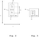
- FIG. 2 a detail view of a second embodiment of the inventive radar target simulator front end is shown.
- the antenna unit 10 here comprises a transmission antenna 20 and a reception antenna 21.
- the transmission antenna 20 is configured to receive the radar signal transmitted by the radar device under test 2, while the reception antenna 21 is configured to transmit a simulated scatter signal back to the radar device under test 2.
- the activation and deactivation of the antenna unit 10 is performed by connecting the transmission antenna 20 to the reception antenna 21, and the deactivation is performed by opening the connection between these two antennas 20, 21.
- the radar target simulator front end 1 is connected to a target simulator back end, not shown here.
- the backend is then configured to process the radar signal received by the reception antenna 21, and therefrom generate a simulated scatter signal, which is then handed to the transmission antenna 20, to be transmitted towards the radar device under test 2.
- the target simulator back end then may comprise a down-converter, configured to perform a downconversion of the radar signal received by the reception antenna 21 to the baseband region.
- the target simulator back end may moreover comprise a baseband processor, configured to add fading, and/or dampening, and/or attenuation, and/or multi-path transmission, and/or noise.
- the target simulator back end may moreover comprise an up-converter, configured to generate the simulated scatter signal, by up-converting the down-converted radar signal received by the reception antenna 21, or by up-converting the processed signal provided by the baseband processor.
- an up-converter configured to generate the simulated scatter signal, by up-converting the down-converted radar signal received by the reception antenna 21, or by up-converting the processed signal provided by the baseband processor.
- a separate target simulator such as for example the R&S AREG may be used as the target simulator back end.
- the first angle under investigation x, and a second angle y, orthogonal to the first angle under investigation x is displayed.
- the transmission antenna 20 and the reception antenna 21 are arranged with regard to each other along the angle y, orthogonal to the first angle under investigation x. This allows for constructing the antenna unit 10 with a very small dimension along the first angle under investigation x, allowing for placing a very high number of antenna units along the first angle under investigation, achieving a high angular resolution.
- the transmission antenna 20 and the reception antenna 21 are placed at an angular distance d of their centers with regard to each other. This angular distance is smaller than an angular resolution of the radar device under test. This prevents phase errors in case of the use of MIMO radar devices under test.
- the distance d of the centers of the antennas is between 1mm and 10mm, more preferably between 2mm and 5mm, most preferably 3mm.
- an angular resolution of 0,02 - 1°, more preferably 0,05-0,5°, most preferably 0,1° is achieved.
- FIG. 3 a further detail view of an embodiment of the inventive radar target simulator front end is shown.
- the antenna unit 10 here comprises a combined transmission/reception antenna 30.
- the transmission/reception antenna 30 is both used for receiving the radar signal transmitted by the radar device under test 2, as well as transmitting the simulated scatter signal to the radar device under test 2.
- the deactivation of the transmission/reception antenna 30 can be achieved by opening a switch connecting different parts of the antenna, significantly altering the frequency response of the antenna, thereby significantly reducing the magnitude of the reflected radar signal.
- the activation in this case occurs by closing this connection again.
- the radar signal received by the transmission/reception antenna 30 is handed to the radar target simulator back end, processed thereby, and a signal for transmission is handed back to the transmission/reception antenna 30.
- the only difference to the setup described along Fig. 2 is that the signal is received and transmitted successively by the same transmission/reception antenna 30 instead of being received by a dedicated reception antenna and then transmitted by a dedicated transmission antenna.
- each antenna module comprises at least 4 antenna units.
- the antenna module then comprises 4 transmission antennas and 4 reception antennas.
- the antenna unit then comprises 4 joint antennas.
- Each of the antenna units may be constructed as a single integrated circuit on a single microchip.
- the antenna units can then be activated separately or jointly.
- the antenna modules may moreover comprise signal distribution hardware, configured to distribute the signals received by the individual antennas to the radar simulator back end and to distribute the signals provided by the radar simulator back end to the individual antennas.
- the antenna modules may moreover comprise a state machine for controlling the individual antennas.
- the antenna modules may furthermore comprise an interface, configured to connect and/or synchronize at least two antenna modules. Especially, a cascading and/or daisy chaining of antenna modules may be performed by this interface.
- the radar simulator back end for example comprises 4 microwave sources and/or up to 8 signal conditioning units for transmission paths, and/or 10 signal conditioning units for reception paths, configured to perform the afore-mentioned processing.
- the radar simulator back end may furthermore comprise a communication unit, configured to perform communication with the radar simulator front end 1.
- FIG. 4 a further embodiment of the inventive radar target simulator front end 1 is shown.
- further antenna units 40, 41, 42 and 43 are arranged along a second angle under investigation y.
- the first angle under investigation x and the second angle under investigation y are orthogonal with regard to each other.
- the setup of FIG. 4 allows for simulating radar targets arranged along the second angle under investigation y, by selectively activating and deactivating the antenna units 40, 41, 42 and 43.
- the antenna unit 13, which is arranged between the antenna units 41 and 42 may also be used as part of the further antenna units 40, 41, 42 and 43, when simulating radar targets arranged along the second angle under investigation y.
- an antenna unit switch 45 is shown.
- the antenna unit switch 45 is connected to each one of the individual antenna units.
- the individual connections are omitted in this figure for reasons of clarity.
- the antenna unit switch 45 performs the activation and deactivation of the individual antenna units, in order to simulate the radar targets.
- FIG. 4 Although in FIG. 4 , only four dedicated antenna units 40, 41, 42 and 43 arranged along the second angle under investigation y are shown, a far greater number might be employed. Especially, also here 50-150, preferably 96 antenna units may be used.
- antenna units 40, 41, 42, and 43 may also be placed adjacent thereto, resulting in a modular design, in which modules of connected antenna units, are placeable as desired.
- One module could for example be formed by the antenna units 10-15 of Fig. 1 .
- FIG. 5 a flow diagram of an exemplary embodiment of the inventive method is shown.
- a first step 100 at least two antenna units arranged along a first angle under investigation are provided.
- antenna units of the at least two antenna units are selectively activated and deactivated.
- a third step 102 a simulated radar target is generated along the first angle under investigation by the activated antenna units of the second step 101.
- the embodiments of the present invention can be implemented by hardware, software, or any combination thereof.
- Various embodiments of the present invention may be implemented by one or more application specific integrated circuits (ASICs), digital signal processors (DSPs), digital signal processing devices (DSPDs), programmable logic devices (PLDs), field programmable gate arrays (FPGAs), processors, controllers, microcontrollers, microprocessors, or the like.
- ASICs application specific integrated circuits
- DSPs digital signal processors
- DSPDs digital signal processing devices
- PLDs programmable logic devices
- FPGAs field programmable gate arrays
- processors controllers, microcontrollers, microprocessors, or the like.
- Various embodiments of the present invention may also be implemented in the form of software modules, processes, functions, or the like which perform the features or operations described above.
- Software code can be stored in a memory unit so that it can be executed by a processor.
- the memory unit may be located inside or outside the processor and can communicate date with the processor through a variety of known means.
- the invention is not limited to the examples and especially not to a specific number of antenna units or frequency of the radar signal.
- the invention discussed above can be applied to many types of radar systems under test.
- the characteristics of the exemplary embodiments can be used in any advantageous combination.
Landscapes
- Engineering & Computer Science (AREA)
- Radar, Positioning & Navigation (AREA)
- Remote Sensing (AREA)
- Physics & Mathematics (AREA)
- Computer Networks & Wireless Communication (AREA)
- General Physics & Mathematics (AREA)
- Electromagnetism (AREA)
- Radar Systems Or Details Thereof (AREA)
Abstract
Description
- The invention relates to testing radar devices, especially testing road vehicle radar devices, and a respective method for simulating a radar target.
- Road vehicle radar devices serve the purpose of detecting objects surrounding the vehicle. In order to test such a radar device, the ability of the device to detect objects under controlled conditions needs to be verified. Conventional test setups use actual target objects, which are placed in the vicinity of the radar device under test and which are actively moved with regard to the radar device under test to simulate movement of a real-world object.
- For example, the document
EP 3 143 712 B1 shows such a conventional radar test system. Such a setup can produce accurate results, but is large and cumbersome and therefore only usable in a development environment, but not in a production test environment. - Accordingly, there is object to provide a radar target simulator front end and a method for simulating, which allow for testing a radar device under test with minimal hardware effort and minimal space requirement.
- The object is solved by the features of the first independent claim for the target simulator frontend and by the features of the second independent claim for the method.
- According to a first aspect of the invention, a radar target simulator front end, configured to simulate at least one radar target for testing a radar device under test is provided. The radar target simulator front end comprises at least two antenna units, arranged along a first angle under investigation. The at least two antenna units are configured to be selectively activated and deactivated. Whereby each antenna unit of the at least two antenna units generates a simulated radar target along the first angle under investigation, when activated. This allows for simulating a radar target at two different positions with regard to the radar device under test without actually performing any physical movement within the system.
- Advantageously and preferably, each of the at least two antenna units comprises a transmission antenna and a reception antenna. This allows for a high signal separation and thereby increases the quality of the radar signal received by the radar device under test.
- Preferably, the transmission antenna and the reception antenna of each of the at least two antenna units are arranged with regard to each other along an angle orthogonal to the first angle under investigation. This allows for reducing the size of the antenna unit along the angle under investigation, which in turn allows for spacing a plurality of antenna units close together along the angle under investigation, increasing the angular resolution that can be tested.
- Advantageously and preferably, the transmission antenna and the reception antenna of each antenna unit are arranged at an angular distance with regard to each other, which is smaller than an angular resolution of the radar device under test. This results in the radar device under test not being able to distinguish the positions of the transmission antenna and the reception antenna, giving the radar device under test the impression of actually measuring a radar reflection of a real-world radar target.
- Alternatively and preferably, each of the at least two antenna units comprises a combined transmission/reception antenna. This reduces the overall size of the antenna unit and at the same time assures that the radar device under test receives radar signals, which are very close to scattered signals of a real-world radar object.
- Advantageously and preferably, the at least two antenna units are configured to be activated jointly, simulating generating at least two simulated radar targets. This allows for performing more complex tests.
- Preferably, the radar target simulator front end is configured to simulate a near-field radar target by jointly activating at least two adjacent antenna units of the at least two antenna units. This allows for an increase in the radar target simulation flexibility.
- Advantageously and preferably, the radar target simulator front end comprises a plurality of antenna units arranged along the first angle under investigation. The plurality of antenna units is configured to be selectively activated and deactivated, each antenna unit of the plurality of antenna units generating a simulated radar target, when activated. This allows for a very high angular resolution and the simulation of smooth movement of a radar target along the first angle under investigation.
- Preferably, the radar target simulator front end moreover comprises at least two further antenna units arranged along a second angle under investigation. The at least two further antenna units are configured to be selectively activated and deactivated, each antenna unit of the at least two further antenna units generating a simulated radar target along the second angle under investigation, when activated. This allows for performing measurements along a second angle under investigation.
- Preferably, the first angle under investigation and the second angle under investigation are orthogonal with regard to each other. This allows for measuring radar targets for example along an azimuth and along an elevation.
- Preferably, the radar target simulator front end is configured to simulate radar targets for testing a multiple-input multiple output, MIMO, radar device under test and/or a multiple-input single-output, MISO, radar device under test. This allows for a very flexible use of the inventive radar target simulator front end.
- Advantageously and preferably, the radar target simulator front end moreover comprises a plurality of antenna units, arranged in a two-dimensional angular pattern. The plurality of antenna units is configured to be selectively activated and deactivated, each antenna unit of the plurality of antenna units generating a simulated radar target at a specific two-dimensional angular position. This allows for placing simulated radar targets as pixels in a two-dimensional grid, resulting in a very high measuring flexibility.
- Preferably, the radar target simulator front end moreover comprises an antenna unit switch, which is configured to selectively activate and deactivate the at least two antenna units. This makes a high degree of automation possible.
- Preferably, the antenna unit switch is configured to successively activate and deactivate adjacent antenna units of the at least two antenna units, simulating a movement of a simulated radar target. This allows for a very simple measuring setup.
- According to a second aspect of the invention, a method for simulating at least one radar target for testing a radar device under test is provided. The method comprises providing at least two antenna units, arranged along a first angle under investigation, selectively activating and deactivating antenna units of the at least two antenna units, and thereby generating a simulated radar target along the first angle under investigation, when activated.
- Preferably, many pairs of antenna units are created in an angle in order to simulate many possible angles under investigation.
- Preferably, the pairs of antenna units are aligned in a specific direction in order to test radar targets along angles in the specific direction.
- Preferably, the pairs of antenna units are designed to be within an angular resolution cell.
- Preferably, a two-dimensional alignment of the antenna units is performed by creating pixels.
- Preferably, a near field target is simulated.
- An exemplary embodiment of the invention is now further explained by way of example only with respect to the drawings, in which
- FIG. 1
- shows a first exemplary embodiment of the inventive radar target simulator front end;
- FIG. 2
- shows a detail view of a second exemplary embodiment of the inventive radar target simulator front end;
- FIG. 3
- shows a detail view of a third exemplary embodiment of the inventive radar target simulator front end;
- FIG. 4
- shows a fourth exemplary embodiment of the inventive radar target simulator front end, and
- FIG. 5
- shows an exemplary embodiment of the inventive method in a flow diagram.
- First, we demonstrate the general concept and function of the invention along
FIG. 1 . With regard toFIG. 2 - FIG. 4 , further details of the invention are explained along different embodiments of the device. Finally, with regard toFIG. 5 , the detailed function of an embodiment of the inventive method is described. Similar entities and reference numbers in different figures have been partially omitted. - Reference will now be made in detail to the preferred embodiments of the present invention, examples of which are illustrated in the accompanying drawings. However, the following embodiments of the present invention may be variously modified and the range of the present invention is not limited by the following embodiments.
- In
FIG. 1 , a first embodiment of the inventive radar target simulatorfront end 1 and a radar device undertest 2 are shown. The radar device undertest 2 is a multiple-input multiple output, MIMO, radar device or a multiple-input single-output, MISO, radar device under test. Even a single-input single-output, SISO, radar device under test can be tested with this setup. - Here, the radar target simulator
front end 1 comprises a number ofantenna units test 2. Here, the antenna units 12-15 are shown using dotted lines, indicating that they constitute optional components. Each of the antenna units 10-15 is configured to be selectively activated and deactivated. In the activated state, the individual antenna unit 10-15 generates a radar reflection, while in the deactivated state, the antenna unit 10-15 does not generate a radar reflection. - During a test, the radar device under
test 2 transmits a radar signal towards the radar target simulatorfront end 1. All active antenna units 10-15 generate a simulated scatter signal and transmit it back to the radar device undertest 2. InFIG. 1 , only theantenna unit 10 is active, resulting in only theantenna unit 10 generating a simulated scatter signal and returning it to the radar device undertest 2. Therefore, theantenna unit 10 simulates a real-world radar target at its position. - With regard to the inner workings of the antenna units 10-15 it is referred to
FIG. 2 and FIG. 3 , which are explained later with regard to the second and third embodiment but works similar here. - For simulating a movement of a real-world radar target along the first angle under investigation x, the antenna units 10-15 can be activated and deactivated successively. For example, in a first instance, only the
antenna unit 10 is active. In a second instance, theantenna unit 10 might be deactivated, while theantenna unit 11 is activated. In a third instance, theantenna unit 11 might be deactivated, while theantenna unit 12 is activated. This simulates a movement of the simulated radar target along the first angle under investigation x. - It is also possible to jointly activate and deactivate at least two of the antenna units 10-15 in order to simulate a larger radar target, or in order to simulate near-field conditions.
- Preferably, the antenna units 10-15 are configured to simulate radar targets when activated, for a radar frequency of 50-130 GHz, preferably 70-90 GHz, most preferably 76-81 GHz.
- Although here only six antenna units 10-15 are displayed, a far greater number of antenna units can be employed. For example, the number of antenna units arranged along the first angle of angle under investigation x might be between 50 and 150 antenna units, preferably 96 antenna units.
- Also, only two antenna units may be used. This still allows a digital movement between two angular positions.
- In
FIG. 2 , a detail view of a second embodiment of the inventive radar target simulator front end is shown. Here, only asingle antenna unit 10 is shown. Theantenna unit 10 here comprises atransmission antenna 20 and areception antenna 21. Thetransmission antenna 20 is configured to receive the radar signal transmitted by the radar device undertest 2, while thereception antenna 21 is configured to transmit a simulated scatter signal back to the radar device undertest 2. - In a most simple configuration, the activation and deactivation of the
antenna unit 10 is performed by connecting thetransmission antenna 20 to thereception antenna 21, and the deactivation is performed by opening the connection between these twoantennas - In a more complex setup, the radar target simulator
front end 1 is connected to a target simulator back end, not shown here. The backend is then configured to process the radar signal received by thereception antenna 21, and therefrom generate a simulated scatter signal, which is then handed to thetransmission antenna 20, to be transmitted towards the radar device undertest 2. - Especially, the target simulator back end then may comprise a down-converter, configured to perform a downconversion of the radar signal received by the
reception antenna 21 to the baseband region. - The target simulator back end may moreover comprise a baseband processor, configured to add fading, and/or dampening, and/or attenuation, and/or multi-path transmission, and/or noise.
- The target simulator back end may moreover comprise an up-converter, configured to generate the simulated scatter signal, by up-converting the down-converted radar signal received by the
reception antenna 21, or by up-converting the processed signal provided by the baseband processor. - Especially, a separate target simulator, such as for example the R&S AREG may be used as the target simulator back end.
- In
FIG. 2 , additionally, the first angle under investigation x, and a second angle y, orthogonal to the first angle under investigation x is displayed. Preferably, thetransmission antenna 20 and thereception antenna 21 are arranged with regard to each other along the angle y, orthogonal to the first angle under investigation x. This allows for constructing theantenna unit 10 with a very small dimension along the first angle under investigation x, allowing for placing a very high number of antenna units along the first angle under investigation, achieving a high angular resolution. - The
transmission antenna 20 and thereception antenna 21 are placed at an angular distance d of their centers with regard to each other. This angular distance is smaller than an angular resolution of the radar device under test. This prevents phase errors in case of the use of MIMO radar devices under test. - Preferably, the distance d of the centers of the antennas is between 1mm and 10mm, more preferably between 2mm and 5mm, most preferably 3mm.
- At a distance of 1-2m between the radar simulator
front end 1 and the radar device undertest 2, preferably, an angular resolution of 0,02 - 1°, more preferably 0,05-0,5°, most preferably 0,1° is achieved. - In
FIG. 3 , a further detail view of an embodiment of the inventive radar target simulator front end is shown. Here, the inner workings of asingle antenna unit 10 are shown. Theantenna unit 10 here comprises a combined transmission/reception antenna 30. The transmission/reception antenna 30 is both used for receiving the radar signal transmitted by the radar device undertest 2, as well as transmitting the simulated scatter signal to the radar device undertest 2. - In a most simple construction, the deactivation of the transmission/
reception antenna 30 can be achieved by opening a switch connecting different parts of the antenna, significantly altering the frequency response of the antenna, thereby significantly reducing the magnitude of the reflected radar signal. The activation in this case occurs by closing this connection again. - In a more complex setup, as described along
Fig. 2 , the radar signal received by the transmission/reception antenna 30 is handed to the radar target simulator back end, processed thereby, and a signal for transmission is handed back to the transmission/reception antenna 30. The only difference to the setup described alongFig. 2 is that the signal is received and transmitted successively by the same transmission/reception antenna 30 instead of being received by a dedicated reception antenna and then transmitted by a dedicated transmission antenna. - In practice, a number of antenna units may be grouped into an antenna modules, also referred to as QAT modules. Each antenna module comprises at least 4 antenna units. In case of the embodiment of
Fig. 2 , the antenna module then comprises 4 transmission antennas and 4 reception antennas. In case of the embodiment ofFig. 3 , the antenna unit then comprises 4 joint antennas. - Each of the antenna units may be constructed as a single integrated circuit on a single microchip.
- The antenna units can then be activated separately or jointly.
- The antenna modules may moreover comprise signal distribution hardware, configured to distribute the signals received by the individual antennas to the radar simulator back end and to distribute the signals provided by the radar simulator back end to the individual antennas.
- Also, the antenna modules may moreover comprise a state machine for controlling the individual antennas.
- The antenna modules may furthermore comprise an interface, configured to connect and/or synchronize at least two antenna modules. Especially, a cascading and/or daisy chaining of antenna modules may be performed by this interface.
- The radar simulator back end for example comprises 4 microwave sources and/or up to 8 signal conditioning units for transmission paths, and/or 10 signal conditioning units for reception paths, configured to perform the afore-mentioned processing.
- The radar simulator back end may furthermore comprise a communication unit, configured to perform communication with the radar simulator
front end 1. - In
FIG. 4 , a further embodiment of the inventive radar target simulatorfront end 1 is shown. Here, in addition to the antenna units 10-15 arranged along the first angle under investigation x,further antenna units - In addition to simulating radar targets arranged along the first angle under investigation x, the setup of
FIG. 4 allows for simulating radar targets arranged along the second angle under investigation y, by selectively activating and deactivating theantenna units antenna unit 13, which is arranged between theantenna units further antenna units - In this embodiment, additionally, an
antenna unit switch 45 is shown. Theantenna unit switch 45 is connected to each one of the individual antenna units. The individual connections are omitted in this figure for reasons of clarity. Theantenna unit switch 45 performs the activation and deactivation of the individual antenna units, in order to simulate the radar targets. - In addition to the two-dimensional arrangement of antenna units 10-15, 40-43, shown here, also a complete two-dimensional grid of antenna units forming pixels might be employed. In this case, a movement of simulated radar targets along the first angle under investigation and along the second angle under investigation at the same time is possible.
- Although in
FIG. 4 , only fourdedicated antenna units - Instead of arranging the
antenna units Fig. 1 . - In
FIG. 5 , a flow diagram of an exemplary embodiment of the inventive method is shown. In afirst step 100 at least two antenna units arranged along a first angle under investigation are provided. In asecond step 101, antenna units of the at least two antenna units are selectively activated and deactivated. In athird step 102, a simulated radar target is generated along the first angle under investigation by the activated antenna units of thesecond step 101. - The embodiments of the present invention can be implemented by hardware, software, or any combination thereof. Various embodiments of the present invention may be implemented by one or more application specific integrated circuits (ASICs), digital signal processors (DSPs), digital signal processing devices (DSPDs), programmable logic devices (PLDs), field programmable gate arrays (FPGAs), processors, controllers, microcontrollers, microprocessors, or the like.
- Various embodiments of the present invention may also be implemented in the form of software modules, processes, functions, or the like which perform the features or operations described above. Software code can be stored in a memory unit so that it can be executed by a processor. The memory unit may be located inside or outside the processor and can communicate date with the processor through a variety of known means.
- The invention is not limited to the examples and especially not to a specific number of antenna units or frequency of the radar signal. The invention discussed above can be applied to many types of radar systems under test. The characteristics of the exemplary embodiments can be used in any advantageous combination.
- Although the present invention and its advantages have been described in detail, it should be understood, that various changes, substitutions and alterations can be made herein without departing from the spirit and scope of the invention as defined by the appended claims.
Claims (20)
- A radar target simulator frontend, configured to simulate at least one radar target for testing a radar device under test,
comprising at least two antenna units, arranged along a first angle under investigation,
wherein the at least two antenna units are configured to be selectively activated and deactivated, each antenna unit of the at least two antenna units generating a simulated radar target along the first angle under investigation, when activated. - The radar target simulator frontend of claim 1, wherein each of the at least two antenna units comprises a transmission antenna and a reception antenna.
- The radar target simulator frontend of claim 2, wherein the transmission antenna and the reception antenna of each of the at least two antenna units are arranged with regard to each other along an angle orthogonal to the first angle under investigation.
- The radar target simulator frontend of claim 2 or 3, wherein the transmission antenna and the reception antenna of each antenna unit are arranged at an angular distance with regard to each other, which is smaller than an angular resolution of the radar device under test.
- The radar target simulator frontend of any of claims 1 to 4,
wherein each of the at least two antenna units comprises a combined transmission/reception antenna. - The radar target simulator frontend of any of claims 1 to 5,
wherein the at least two antenna units are configured to be activated jointly, simultaneously generating at least two simulated radar targets. - The radar target simulator frontend of any of claims 1 to 6,
wherein the radar target simulator frontend is configured to simulate a near field radar target by jointly activating at least two adjacent antenna units of the at least two antenna units. - The radar target simulator frontend of any of claims 1 to 7,
comprising a plurality of antenna units, arranged along the first angle under investigation,
wherein the plurality of antenna units are configured to be selectively activated and deactivated, each antenna unit of the plurality of antenna units generating a simulated radar target, when activated. - The radar target simulator frontend of any of claims 1 to 8,
comprising at least two further antenna units, arranged along a second angle under investigation,
wherein the at least two further antenna units are configured to be selectively activated and deactivated, each antenna unit of the at least two further antenna units generating a simulated radar target along the second angle under investigation, when activated. - The radar target simulator frontend of claim 8 or 9,
wherein the first angle under investigation and the second angle under investigation are orthogonal with regard to each other. - The radar target simulator frontend of any of claims 1 to 10,
wherein the radar target simulator frontend is configured to simulate radar targets for testing a multiple input multiple output, MIMO, radar device under test or a multiple input single output, MISO, radar device under test. - The radar target simulator frontend of any of claims 1 to 11,
comprising a plurality of antenna units,
wherein the plurality of antenna units are arranged in a two-dimensional angular pattern,
wherein the plurality of antenna units are configured to be selectively activated and deactivated, each antenna unit of the plurality of antenna units generating a simulated radar target at a specific two-dimensional angular position. - The radar target simulator frontend of any of claims 1 to 12, comprising an antenna unit switch, configured to selectively activate and deactivate the at least two antenna units.
- The radar target simulator frontend of claim 13, wherein the antenna unit switch is configured to successively active and deactivate directly adjacent antenna units of the at least two antenna units, simulating a movement of a simulated radar target.
- A method for simulating at least one radar target for testing a radar device under test, comprising:- providing at least two antenna units, arranged along a first angle under investigation,- selectively activating and deactivating antenna units of the at least two antenna units, and- thereby generating a simulated radar target along the first angle under investigation, when activated.
- The method of claim 15,
wherein many pairs of antenna units are created in an angle in order to simulate many possible angles under investigation. - The method of claim 16,
wherein the pairs of antenna units are aligned in a specific direction in order to test radar targets along angles in the specific direction. - The method of claim 16 or 17,
wherein the pairs of antenna units are designed to be within an angular resolution cell. - The method of any of claims 15 to 18,
wherein a two-dimensional alignment of the antenna units is performed by creating pixels. - The method of any of claims 15 to 19,
wherein a near field target is simulated.
Applications Claiming Priority (1)
| Application Number | Priority Date | Filing Date | Title |
|---|---|---|---|
| US16/888,056 US11914070B2 (en) | 2020-05-29 | 2020-05-29 | Radar target simulator front end and method for simulating |
Publications (3)
| Publication Number | Publication Date |
|---|---|
| EP3916420A1 true EP3916420A1 (en) | 2021-12-01 |
| EP3916420B1 EP3916420B1 (en) | 2023-08-02 |
| EP3916420B8 EP3916420B8 (en) | 2023-09-06 |
Family
ID=74236119
Family Applications (1)
| Application Number | Title | Priority Date | Filing Date |
|---|---|---|---|
| EP21153376.5A Active EP3916420B8 (en) | 2020-05-29 | 2021-01-26 | Radar target simulator front end and method for simulating |
Country Status (3)
| Country | Link |
|---|---|
| US (1) | US11914070B2 (en) |
| EP (1) | EP3916420B8 (en) |
| CN (1) | CN113740814B (en) |
Cited By (2)
| Publication number | Priority date | Publication date | Assignee | Title |
|---|---|---|---|---|
| EP4644947A1 (en) * | 2024-04-30 | 2025-11-05 | BAE SYSTEMS plc | Improved virtual target generator |
| WO2025229301A1 (en) * | 2024-04-30 | 2025-11-06 | Bae Systems Plc | Improvements in and relating to target generators |
Families Citing this family (7)
| Publication number | Priority date | Publication date | Assignee | Title |
|---|---|---|---|---|
| US11867832B2 (en) | 2021-02-15 | 2024-01-09 | Keysight Technologies, Inc. | Separating receive and transmit antennas of a radar test system |
| US12436236B2 (en) * | 2022-09-20 | 2025-10-07 | Dspace Gmbh | Method and system for testing a radar sensor for an active environment sensing system |
| US12436238B2 (en) | 2023-02-24 | 2025-10-07 | Keysight Technologies, Inc. | Emulation of spatially distributed objects with a sparsely populated array of radar target simulators |
| US12669579B2 (en) | 2023-09-27 | 2026-06-30 | Keysight Technologies, Inc. | Methods, systems, and computer readable media for phase-conjugate radar target emulation for testing dual sideband (DSB) frequency modulated continuous wave (FMCW) radars |
| US12579903B1 (en) * | 2023-11-20 | 2026-03-17 | United States Of America, As Represented By The Secretary Of The Navy | Radar measurement via characterization |
| US12613312B2 (en) * | 2024-01-29 | 2026-04-28 | Keysight Technologies, Inc. | System and method for emulating multipath effects of radar |
| CN120405593B (en) * | 2025-07-01 | 2025-09-02 | 中国电子科技集团公司第二十九研究所 | Single-channel multi-angle target simulation method and system |
Citations (4)
| Publication number | Priority date | Publication date | Assignee | Title |
|---|---|---|---|---|
| US4660041A (en) * | 1983-09-22 | 1987-04-21 | Boeing Aerospace Company | Radar scene simulator |
| EP1034442A1 (en) * | 1997-11-21 | 2000-09-13 | Raytheon Company | Automotive forward looking sensor test station |
| EP3143712B1 (en) | 2014-05-12 | 2018-01-31 | Robert Bosch GmbH | Method for calibrating a mimo radar sensor for motor vehicles |
| FR3071346A1 (en) * | 2017-09-21 | 2019-03-22 | Renault S.A.S. | SYSTEM FOR SIMULATING A SCENARIO INVOLVING A SIDE MOTION OF A TARGET AND ASSOCIATED METHOD |
Family Cites Families (21)
| Publication number | Priority date | Publication date | Assignee | Title |
|---|---|---|---|---|
| CN102043143B (en) | 2010-11-09 | 2013-12-11 | 河海大学 | Simulation method for statistical MIMO (multiple input multiple output) radar target detection |
| US20120274499A1 (en) | 2011-04-29 | 2012-11-01 | Spatial Digital Systems | Radar imaging via spatial spectrum measurement and MIMO waveforms |
| WO2013058842A1 (en) * | 2011-06-29 | 2013-04-25 | Technology Service Corporation | Systems and methods for near field target simulation |
| CN104459685B (en) | 2014-11-05 | 2017-02-15 | 河海大学 | Multi-target high-speed positioning method for statistic MIMO radar |
| CN104614713B (en) * | 2015-02-03 | 2016-11-30 | 北京航空航天大学 | A kind of ship that is suitable for carries the radar echo signal simulator of radar system |
| CN104614726B (en) | 2015-03-05 | 2017-05-10 | 北京航空航天大学 | Telescopic array type portable MIMO-SAR (multiple-input multiple-output synthetic aperture radar) measurement radar system and imaging method thereof |
| CN105353367A (en) | 2015-11-26 | 2016-02-24 | 中国人民解放军63921部队 | Bistatic MIMO radar space maneuvering target tracking method |
| CN105842674B (en) | 2016-04-18 | 2018-06-29 | 南京工程学院 | A kind of statistics MIMO radar multi-target detection emulation mode |
| US10527715B2 (en) * | 2016-06-20 | 2020-01-07 | Rohde & Schwarz Gmbh & Co. Kg | Radar target stimulation device and method |
| CN106443615B (en) | 2016-08-23 | 2019-03-29 | 西安电子科技大学 | A Bistatic MIMO Radar High-speed Target Cross-Range Gate Velocity Locating Method |
| CN106291540A (en) | 2016-09-14 | 2017-01-04 | 河北省电力勘测设计研究院 | A kind of multiple-input and multiple-output GPR backwards projection target imaging method estimated based on DOA |
| US10677918B2 (en) | 2017-02-28 | 2020-06-09 | Analog Devices, Inc. | Systems and methods for improved angular resolution in multiple-input multiple-output (MIMO) radar |
| CN107300693A (en) * | 2017-06-29 | 2017-10-27 | 成都瑞达物联科技有限公司 | Millimetre-wave radar performance evaluation simulation system |
| CN207528910U (en) * | 2017-11-16 | 2018-06-22 | 北京经纬恒润科技有限公司 | A kind of radar simulator and angle simulator |
| CN111656217B (en) * | 2018-01-30 | 2023-06-27 | 傲酷公司 | System and method for virtual aperture radar tracking |
| DE102018210070A1 (en) | 2018-06-21 | 2019-12-24 | Robert Bosch Gmbh | Procedure for calibrating a MIMO radar sensor for motor vehicles |
| EP3588128B1 (en) | 2018-06-26 | 2022-08-10 | Fraunhofer-Gesellschaft zur Förderung der angewandten Forschung e.V. | Method for detection and height and azimuth estimation of objects in a scene by radar processing using sparse reconstruction with coherent and incoherent arrays |
| US10852393B2 (en) | 2018-07-30 | 2020-12-01 | GM Global Technology Operations LLC | Method of calibrating a radar system |
| CZ201945A3 (en) * | 2019-01-29 | 2020-03-11 | České vysoké učenà technické v Praze | Target simulator for automotive radars with a range of radio transponders |
| CN110031813B (en) * | 2019-05-21 | 2024-04-16 | 吉林大学 | Vehicle-mounted millimeter-wave radar test system for multi-target dynamic simulation |
| CN110609259A (en) * | 2019-10-15 | 2019-12-24 | 北京遥感设备研究所 | A vehicle-mounted millimeter-wave radar test system |
-
2020
- 2020-05-29 US US16/888,056 patent/US11914070B2/en active Active
-
2021
- 2021-01-26 EP EP21153376.5A patent/EP3916420B8/en active Active
- 2021-02-05 CN CN202110161760.0A patent/CN113740814B/en active Active
Patent Citations (4)
| Publication number | Priority date | Publication date | Assignee | Title |
|---|---|---|---|---|
| US4660041A (en) * | 1983-09-22 | 1987-04-21 | Boeing Aerospace Company | Radar scene simulator |
| EP1034442A1 (en) * | 1997-11-21 | 2000-09-13 | Raytheon Company | Automotive forward looking sensor test station |
| EP3143712B1 (en) | 2014-05-12 | 2018-01-31 | Robert Bosch GmbH | Method for calibrating a mimo radar sensor for motor vehicles |
| FR3071346A1 (en) * | 2017-09-21 | 2019-03-22 | Renault S.A.S. | SYSTEM FOR SIMULATING A SCENARIO INVOLVING A SIDE MOTION OF A TARGET AND ASSOCIATED METHOD |
Non-Patent Citations (1)
| Title |
|---|
| LEFEVRE R ET AL: "Smart repeater for radar testing", AUTOTESTCON '98. IEEE SYSTEMS READINESS TECHNOLOGY CONFERENCE., 1998 I EEE SALT LAKE CITY, UT, USA 24-27 AUG. 1998, NEW YORK, NY, USA,IEEE, US, 24 August 1998 (1998-08-24), pages 611 - 614, XP010299382, ISBN: 978-0-7803-4420-4, DOI: 10.1109/AUTEST.1998.713506 * |
Cited By (2)
| Publication number | Priority date | Publication date | Assignee | Title |
|---|---|---|---|---|
| EP4644947A1 (en) * | 2024-04-30 | 2025-11-05 | BAE SYSTEMS plc | Improved virtual target generator |
| WO2025229301A1 (en) * | 2024-04-30 | 2025-11-06 | Bae Systems Plc | Improvements in and relating to target generators |
Also Published As
| Publication number | Publication date |
|---|---|
| US11914070B2 (en) | 2024-02-27 |
| US20210373122A1 (en) | 2021-12-02 |
| CN113740814B (en) | 2025-11-25 |
| EP3916420B1 (en) | 2023-08-02 |
| EP3916420B8 (en) | 2023-09-06 |
| CN113740814A (en) | 2021-12-03 |
Similar Documents
| Publication | Publication Date | Title |
|---|---|---|
| US11914070B2 (en) | Radar target simulator front end and method for simulating | |
| CN112415480B (en) | Multiple-input multiple-output (MIMO) target simulation system and method for testing millimeter-wave radar sensors | |
| CN111856414B (en) | Dynamic echo signal simulation for automotive radar sensor configuration | |
| JP2019097207A (en) | System and method for testing radio frequency wireless signal transceivers using wireless test signals | |
| EP3392669A1 (en) | Method and apparatus for radar accuracy measurements | |
| CN102012504B (en) | Dynamic target simulator for airborne secondary radar phased array inquiry system | |
| CN107238825A (en) | RCS method of testing when a kind of utilization vector network instrument realizes antenna transmitting | |
| CN106707253B (en) | A test device and method for combating a networked radar and a networked jammer in a laboratory | |
| CN108494512B (en) | A millimeter wave massive MIMO channel simulation system and method | |
| US12436236B2 (en) | Method and system for testing a radar sensor for an active environment sensing system | |
| Zhang et al. | Over-the-air diagnosis of 1-bit RIS based on amplitude-only measurement | |
| EP3376240B1 (en) | Measuring system and method with digital quiet zone | |
| US12360211B2 (en) | Signal delay device and simulator device for simulating spatial distances in distance measuring devices based on electromagnetic waves | |
| CN108802668A (en) | A kind of multifunctional radiation source angle of arrival simulator and method | |
| EP4099046A1 (en) | Apparatuses and method involving diagnostics of radar circuitry | |
| SE525889C2 (en) | Simulator for complex radar targets | |
| CZ201945A3 (en) | Target simulator for automotive radars with a range of radio transponders | |
| US20220404464A1 (en) | Device and method for testing a distance sensor | |
| CN119439088A (en) | Method and system for accurate simulation of multi-target spatial positions in radio frequency arrays | |
| TWI624160B (en) | Throughput measurement system for multiple input multiple output antennas | |
| JP2004070922A (en) | Module testing device | |
| KR102916311B1 (en) | Near-field test system and near-field test method | |
| KR102916976B1 (en) | Near-field test system and near-field test method | |
| JP7379219B2 (en) | Radar system testing equipment and equipment | |
| CN219302650U (en) | Radio frequency test adapting device |
Legal Events
| Date | Code | Title | Description |
|---|---|---|---|
| PUAI | Public reference made under article 153(3) epc to a published international application that has entered the european phase |
Free format text: ORIGINAL CODE: 0009012 |
|
| STAA | Information on the status of an ep patent application or granted ep patent |
Free format text: STATUS: THE APPLICATION HAS BEEN PUBLISHED |
|
| AK | Designated contracting states |
Kind code of ref document: A1 Designated state(s): AL AT BE BG CH CY CZ DE DK EE ES FI FR GB GR HR HU IE IS IT LI LT LU LV MC MK MT NL NO PL PT RO RS SE SI SK SM TR |
|
| B565 | Issuance of search results under rule 164(2) epc |
Effective date: 20210708 |
|
| STAA | Information on the status of an ep patent application or granted ep patent |
Free format text: STATUS: REQUEST FOR EXAMINATION WAS MADE |
|
| 17P | Request for examination filed |
Effective date: 20211209 |
|
| RBV | Designated contracting states (corrected) |
Designated state(s): AL AT BE BG CH CY CZ DE DK EE ES FI FR GB GR HR HU IE IS IT LI LT LU LV MC MK MT NL NO PL PT RO RS SE SI SK SM TR |
|
| GRAP | Despatch of communication of intention to grant a patent |
Free format text: ORIGINAL CODE: EPIDOSNIGR1 |
|
| STAA | Information on the status of an ep patent application or granted ep patent |
Free format text: STATUS: GRANT OF PATENT IS INTENDED |
|
| GRAS | Grant fee paid |
Free format text: ORIGINAL CODE: EPIDOSNIGR3 |
|
| INTG | Intention to grant announced |
Effective date: 20230414 |
|
| GRAA | (expected) grant |
Free format text: ORIGINAL CODE: 0009210 |
|
| STAA | Information on the status of an ep patent application or granted ep patent |
Free format text: STATUS: THE PATENT HAS BEEN GRANTED |
|
| P01 | Opt-out of the competence of the unified patent court (upc) registered |
Effective date: 20230525 |
|
| AK | Designated contracting states |
Kind code of ref document: B1 Designated state(s): AL AT BE BG CH CY CZ DE DK EE ES FI FR GB GR HR HU IE IS IT LI LT LU LV MC MK MT NL NO PL PT RO RS SE SI SK SM TR |
|
| REG | Reference to a national code |
Ref country code: GB Ref legal event code: FG4D |
|
| REG | Reference to a national code |
Ref country code: DE Ref legal event code: R096 Ref document number: 602021003849 Country of ref document: DE |
|
| RBV | Designated contracting states (corrected) |
Designated state(s): AL AT BE BG CY CZ DE DK EE ES FI FR GB GR HR HU IS IT LT LU LV MC MK MT NL NO PL PT RO RS SE SI SK SM TR |
|
| REG | Reference to a national code |
Ref country code: IE Ref legal event code: FG4D |
|
| REG | Reference to a national code |
Ref country code: LT Ref legal event code: MG9D |
|
| REG | Reference to a national code |
Ref country code: NL Ref legal event code: MP Effective date: 20230802 |
|
| REG | Reference to a national code |
Ref country code: AT Ref legal event code: MK05 Ref document number: 1595408 Country of ref document: AT Kind code of ref document: T Effective date: 20230802 |
|
| PG25 | Lapsed in a contracting state [announced via postgrant information from national office to epo] |
Ref country code: GR Free format text: LAPSE BECAUSE OF FAILURE TO SUBMIT A TRANSLATION OF THE DESCRIPTION OR TO PAY THE FEE WITHIN THE PRESCRIBED TIME-LIMIT Effective date: 20231103 |
|
| PG25 | Lapsed in a contracting state [announced via postgrant information from national office to epo] |
Ref country code: IS Free format text: LAPSE BECAUSE OF FAILURE TO SUBMIT A TRANSLATION OF THE DESCRIPTION OR TO PAY THE FEE WITHIN THE PRESCRIBED TIME-LIMIT Effective date: 20231202 |
|
| PG25 | Lapsed in a contracting state [announced via postgrant information from national office to epo] |
Ref country code: SE Free format text: LAPSE BECAUSE OF FAILURE TO SUBMIT A TRANSLATION OF THE DESCRIPTION OR TO PAY THE FEE WITHIN THE PRESCRIBED TIME-LIMIT Effective date: 20230802 Ref country code: RS Free format text: LAPSE BECAUSE OF FAILURE TO SUBMIT A TRANSLATION OF THE DESCRIPTION OR TO PAY THE FEE WITHIN THE PRESCRIBED TIME-LIMIT Effective date: 20230802 Ref country code: PT Free format text: LAPSE BECAUSE OF FAILURE TO SUBMIT A TRANSLATION OF THE DESCRIPTION OR TO PAY THE FEE WITHIN THE PRESCRIBED TIME-LIMIT Effective date: 20231204 Ref country code: NO Free format text: LAPSE BECAUSE OF FAILURE TO SUBMIT A TRANSLATION OF THE DESCRIPTION OR TO PAY THE FEE WITHIN THE PRESCRIBED TIME-LIMIT Effective date: 20231102 Ref country code: NL Free format text: LAPSE BECAUSE OF FAILURE TO SUBMIT A TRANSLATION OF THE DESCRIPTION OR TO PAY THE FEE WITHIN THE PRESCRIBED TIME-LIMIT Effective date: 20230802 Ref country code: LV Free format text: LAPSE BECAUSE OF FAILURE TO SUBMIT A TRANSLATION OF THE DESCRIPTION OR TO PAY THE FEE WITHIN THE PRESCRIBED TIME-LIMIT Effective date: 20230802 Ref country code: LT Free format text: LAPSE BECAUSE OF FAILURE TO SUBMIT A TRANSLATION OF THE DESCRIPTION OR TO PAY THE FEE WITHIN THE PRESCRIBED TIME-LIMIT Effective date: 20230802 Ref country code: IS Free format text: LAPSE BECAUSE OF FAILURE TO SUBMIT A TRANSLATION OF THE DESCRIPTION OR TO PAY THE FEE WITHIN THE PRESCRIBED TIME-LIMIT Effective date: 20231202 Ref country code: HR Free format text: LAPSE BECAUSE OF FAILURE TO SUBMIT A TRANSLATION OF THE DESCRIPTION OR TO PAY THE FEE WITHIN THE PRESCRIBED TIME-LIMIT Effective date: 20230802 Ref country code: GR Free format text: LAPSE BECAUSE OF FAILURE TO SUBMIT A TRANSLATION OF THE DESCRIPTION OR TO PAY THE FEE WITHIN THE PRESCRIBED TIME-LIMIT Effective date: 20231103 Ref country code: FI Free format text: LAPSE BECAUSE OF FAILURE TO SUBMIT A TRANSLATION OF THE DESCRIPTION OR TO PAY THE FEE WITHIN THE PRESCRIBED TIME-LIMIT Effective date: 20230802 Ref country code: AT Free format text: LAPSE BECAUSE OF FAILURE TO SUBMIT A TRANSLATION OF THE DESCRIPTION OR TO PAY THE FEE WITHIN THE PRESCRIBED TIME-LIMIT Effective date: 20230802 |
|
| PG25 | Lapsed in a contracting state [announced via postgrant information from national office to epo] |
Ref country code: PL Free format text: LAPSE BECAUSE OF FAILURE TO SUBMIT A TRANSLATION OF THE DESCRIPTION OR TO PAY THE FEE WITHIN THE PRESCRIBED TIME-LIMIT Effective date: 20230802 |
|
| PG25 | Lapsed in a contracting state [announced via postgrant information from national office to epo] |
Ref country code: ES Free format text: LAPSE BECAUSE OF FAILURE TO SUBMIT A TRANSLATION OF THE DESCRIPTION OR TO PAY THE FEE WITHIN THE PRESCRIBED TIME-LIMIT Effective date: 20230802 |
|
| PG25 | Lapsed in a contracting state [announced via postgrant information from national office to epo] |
Ref country code: SM Free format text: LAPSE BECAUSE OF FAILURE TO SUBMIT A TRANSLATION OF THE DESCRIPTION OR TO PAY THE FEE WITHIN THE PRESCRIBED TIME-LIMIT Effective date: 20230802 Ref country code: RO Free format text: LAPSE BECAUSE OF FAILURE TO SUBMIT A TRANSLATION OF THE DESCRIPTION OR TO PAY THE FEE WITHIN THE PRESCRIBED TIME-LIMIT Effective date: 20230802 Ref country code: ES Free format text: LAPSE BECAUSE OF FAILURE TO SUBMIT A TRANSLATION OF THE DESCRIPTION OR TO PAY THE FEE WITHIN THE PRESCRIBED TIME-LIMIT Effective date: 20230802 Ref country code: EE Free format text: LAPSE BECAUSE OF FAILURE TO SUBMIT A TRANSLATION OF THE DESCRIPTION OR TO PAY THE FEE WITHIN THE PRESCRIBED TIME-LIMIT Effective date: 20230802 Ref country code: DK Free format text: LAPSE BECAUSE OF FAILURE TO SUBMIT A TRANSLATION OF THE DESCRIPTION OR TO PAY THE FEE WITHIN THE PRESCRIBED TIME-LIMIT Effective date: 20230802 Ref country code: CZ Free format text: LAPSE BECAUSE OF FAILURE TO SUBMIT A TRANSLATION OF THE DESCRIPTION OR TO PAY THE FEE WITHIN THE PRESCRIBED TIME-LIMIT Effective date: 20230802 Ref country code: SK Free format text: LAPSE BECAUSE OF FAILURE TO SUBMIT A TRANSLATION OF THE DESCRIPTION OR TO PAY THE FEE WITHIN THE PRESCRIBED TIME-LIMIT Effective date: 20230802 |
|
| REG | Reference to a national code |
Ref country code: DE Ref legal event code: R097 Ref document number: 602021003849 Country of ref document: DE |
|
| PG25 | Lapsed in a contracting state [announced via postgrant information from national office to epo] |
Ref country code: IT Free format text: LAPSE BECAUSE OF FAILURE TO SUBMIT A TRANSLATION OF THE DESCRIPTION OR TO PAY THE FEE WITHIN THE PRESCRIBED TIME-LIMIT Effective date: 20230802 |
|
| PLBE | No opposition filed within time limit |
Free format text: ORIGINAL CODE: 0009261 |
|
| STAA | Information on the status of an ep patent application or granted ep patent |
Free format text: STATUS: NO OPPOSITION FILED WITHIN TIME LIMIT |
|
| 26N | No opposition filed |
Effective date: 20240503 |
|
| PG25 | Lapsed in a contracting state [announced via postgrant information from national office to epo] |
Ref country code: SI Free format text: LAPSE BECAUSE OF FAILURE TO SUBMIT A TRANSLATION OF THE DESCRIPTION OR TO PAY THE FEE WITHIN THE PRESCRIBED TIME-LIMIT Effective date: 20230802 |
|
| PG25 | Lapsed in a contracting state [announced via postgrant information from national office to epo] |
Ref country code: MC Free format text: LAPSE BECAUSE OF FAILURE TO SUBMIT A TRANSLATION OF THE DESCRIPTION OR TO PAY THE FEE WITHIN THE PRESCRIBED TIME-LIMIT Effective date: 20230802 |
|
| PG25 | Lapsed in a contracting state [announced via postgrant information from national office to epo] |
Ref country code: MC Free format text: LAPSE BECAUSE OF FAILURE TO SUBMIT A TRANSLATION OF THE DESCRIPTION OR TO PAY THE FEE WITHIN THE PRESCRIBED TIME-LIMIT Effective date: 20230802 |
|
| PG25 | Lapsed in a contracting state [announced via postgrant information from national office to epo] |
Ref country code: LU Free format text: LAPSE BECAUSE OF NON-PAYMENT OF DUE FEES Effective date: 20240126 |
|
| PG25 | Lapsed in a contracting state [announced via postgrant information from national office to epo] |
Ref country code: LU Free format text: LAPSE BECAUSE OF NON-PAYMENT OF DUE FEES Effective date: 20240126 |
|
| PG25 | Lapsed in a contracting state [announced via postgrant information from national office to epo] |
Ref country code: BE Free format text: LAPSE BECAUSE OF NON-PAYMENT OF DUE FEES Effective date: 20240131 |
|
| PG25 | Lapsed in a contracting state [announced via postgrant information from national office to epo] |
Ref country code: BE Free format text: LAPSE BECAUSE OF NON-PAYMENT OF DUE FEES Effective date: 20240131 |
|
| REG | Reference to a national code |
Ref country code: BE Ref legal event code: MM Effective date: 20240131 |
|
| PG25 | Lapsed in a contracting state [announced via postgrant information from national office to epo] |
Ref country code: BG Free format text: LAPSE BECAUSE OF FAILURE TO SUBMIT A TRANSLATION OF THE DESCRIPTION OR TO PAY THE FEE WITHIN THE PRESCRIBED TIME-LIMIT Effective date: 20230802 |
|
| PG25 | Lapsed in a contracting state [announced via postgrant information from national office to epo] |
Ref country code: BG Free format text: LAPSE BECAUSE OF FAILURE TO SUBMIT A TRANSLATION OF THE DESCRIPTION OR TO PAY THE FEE WITHIN THE PRESCRIBED TIME-LIMIT Effective date: 20230802 |
|
| PG25 | Lapsed in a contracting state [announced via postgrant information from national office to epo] |
Ref country code: CY Free format text: LAPSE BECAUSE OF FAILURE TO SUBMIT A TRANSLATION OF THE DESCRIPTION OR TO PAY THE FEE WITHIN THE PRESCRIBED TIME-LIMIT; INVALID AB INITIO Effective date: 20210126 |
|
| PG25 | Lapsed in a contracting state [announced via postgrant information from national office to epo] |
Ref country code: HU Free format text: LAPSE BECAUSE OF FAILURE TO SUBMIT A TRANSLATION OF THE DESCRIPTION OR TO PAY THE FEE WITHIN THE PRESCRIBED TIME-LIMIT; INVALID AB INITIO Effective date: 20210126 |
|
| PG25 | Lapsed in a contracting state [announced via postgrant information from national office to epo] |
Ref country code: TR Free format text: LAPSE BECAUSE OF FAILURE TO SUBMIT A TRANSLATION OF THE DESCRIPTION OR TO PAY THE FEE WITHIN THE PRESCRIBED TIME-LIMIT Effective date: 20230802 |
|
| PGFP | Annual fee paid to national office [announced via postgrant information from national office to epo] |
Ref country code: GB Payment date: 20260122 Year of fee payment: 6 |
|
| PGFP | Annual fee paid to national office [announced via postgrant information from national office to epo] |
Ref country code: DE Payment date: 20260120 Year of fee payment: 6 |
|
| PGFP | Annual fee paid to national office [announced via postgrant information from national office to epo] |
Ref country code: FR Payment date: 20260128 Year of fee payment: 6 |