EP3916371A1 - A compressible electrode - Google Patents
A compressible electrode Download PDFInfo
- Publication number
- EP3916371A1 EP3916371A1 EP20177428.8A EP20177428A EP3916371A1 EP 3916371 A1 EP3916371 A1 EP 3916371A1 EP 20177428 A EP20177428 A EP 20177428A EP 3916371 A1 EP3916371 A1 EP 3916371A1
- Authority
- EP
- European Patent Office
- Prior art keywords
- stably
- polymer layer
- deformable polymer
- electrode
- deformed portion
- Prior art date
- Legal status (The legal status is an assumption and is not a legal conclusion. Google has not performed a legal analysis and makes no representation as to the accuracy of the status listed.)
- Withdrawn
Links
Images




Classifications
-
- G—PHYSICS
- G01—MEASURING; TESTING
- G01L—MEASURING FORCE, STRESS, TORQUE, WORK, MECHANICAL POWER, MECHANICAL EFFICIENCY, OR FLUID PRESSURE
- G01L1/00—Measuring force or stress, in general
- G01L1/14—Measuring force or stress, in general by measuring variations in capacitance or inductance of electrical elements, e.g. by measuring variations of frequency of electrical oscillators
- G01L1/142—Measuring force or stress, in general by measuring variations in capacitance or inductance of electrical elements, e.g. by measuring variations of frequency of electrical oscillators using capacitors
-
- G—PHYSICS
- G01—MEASURING; TESTING
- G01L—MEASURING FORCE, STRESS, TORQUE, WORK, MECHANICAL POWER, MECHANICAL EFFICIENCY, OR FLUID PRESSURE
- G01L1/00—Measuring force or stress, in general
- G01L1/14—Measuring force or stress, in general by measuring variations in capacitance or inductance of electrical elements, e.g. by measuring variations of frequency of electrical oscillators
- G01L1/142—Measuring force or stress, in general by measuring variations in capacitance or inductance of electrical elements, e.g. by measuring variations of frequency of electrical oscillators using capacitors
- G01L1/146—Measuring force or stress, in general by measuring variations in capacitance or inductance of electrical elements, e.g. by measuring variations of frequency of electrical oscillators using capacitors for measuring force distributions, e.g. using force arrays
-
- G—PHYSICS
- G01—MEASURING; TESTING
- G01M—TESTING STATIC OR DYNAMIC BALANCE OF MACHINES OR STRUCTURES; TESTING OF STRUCTURES OR APPARATUS, NOT OTHERWISE PROVIDED FOR
- G01M99/00—Subject matter not provided for in other groups of this subclass
- G01M99/001—Testing of furniture, e.g. seats or mattresses
Definitions
- the present inventive concept relates to the field of compressible electrodes.
- a compressible electrode and a capacitive pressure sensor comprising a compressible electrode.
- a basic capacitive pressure sensor consists of two electrodes with a dielectric in between the electrodes. By applying force/pressure on the sensor, either the dielectric, and/or at least one of the electrodes are deformed, resulting in a measurable change of capacitance value of the sensor. For achieving a high sensitivity and high values of capacitance per unit area, compressible electrodes are usually used in the sensors.
- a compressible electrode may consist of an electrically non-conductive, deformable polymer with electrically conductive fillers making the deformable polymer electrically conductive, resulting in an electrically conductive polymer composite.
- the compressible electrode may also, as an alternative, be a non-conductive polymer coated with a conductive layer.
- An example of a compressible electrode is disclosed in US 9,752,940 , in which the electrode has a single polymer layer with embedded conductive particles or a conductive layer arranged onto the single polymer layer.
- the non-conductive polymer used should be soft, e.g. a silicone rubber material or a gel, but problems often arise with adhesion capacity of the conductive coating to such soft polymers. Further, the adhesion process itself may need to be performed on non-flat surfaces that are not standard within the art.
- a compressible electrode comprising a stably deformable polymer layer comprising a first outer surface, a second outer surface, at least one deformed portion formed as at least one indentation in the first outer surface and at least one corresponding protrusion in the second outer surface, and at least one non-deformed portion.
- the compressible electrode further comprises at least one stretchable conductor layer arranged on or within the stably deformable polymer layer at the at least one deformed portion and/or at the at least one non-deformed portion; and wherein the stably deformable polymer layer is stably deformed stably deformed at the at least one deformed portion.
- the compressible electrode further comprises an elastic material arranged on the first outer surface such that the elastic material fills the at least one indentation of said at least one deformed portion.
- the stably deformable polymer layer may be in the form of a sheet or layer and may form a substrate or a carrier for the stretchable conductor layer during e.g. deposition and printing of the stretchable conductor layer onto the stably deformable polymer layer.
- the stretchable conductor layer may be arranged within the stably deformable polymer layer, i.e. be embedded in the stably deformable polymer layer.
- the stably deformable polymer layer may be any polymer layer that may be deformed into a stable, deformed shape.
- the stably deformable polymer layer will retain the stable, deformed shape in the absence of any external force on the stably deformable polymer layer.
- a deformation of the stably deformable polymer layer may be achieved by subjecting the stably deformable polymer layer to external conditions causing the deformation.
- the deformation may be caused by one or more of heating, applying a pressure or a vacuum on the stably deformable polymer layer.
- the deformation may be achieved by a thermoforming process, which may include heating, shaping and cooling of the stably deformable polymer layer, for bringing the stably deformable polymer layer into a deformed shape, which may or may not be a predetermined shape of the stably deformable polymer layer.
- the stably deformable polymer layer may be a thermoformable polymer layer, such as formed by a thermoset material or a thermoplastic material.
- the stably deformable polymer layer may be configured to be irreversibly deformed into a deformed shape.
- the stably deformable polymer layer may be formed by a thermoset material, which may be irreversibly deformed into a deformed shape by curing, such as heating.
- the stably deformable polymer layer may be configured to be reversibly deformed, such that the stably deformable polymer layer may be deformed and, upon being subjected to a sufficient external force, the stably deformable polymer layer may be re-shaped.
- the stably deformable polymer layer may be formed by a thermoplastic material, which may be deformed into a deformed shape by e.g. a thermoforming process and which may be re-shaped by again heating the thermoplastic material above its melting temperature, reshaping it, followed by cooling it down below its melting temperature.
- the stably deformable polymer layer may alternatively be formed by a shape memory polymer, which may be deformed from a primary shape into a secondary predetermined deformed shape by heating it above its glass transition temperature and deforming it into said secondary predetermined deformed shape, followed by cooling it down below its glass transition temperature, and may be further returned into its primary shape, e.g. by heating the shape memory polymer above its glass transition temperature.
- the stably deformable polymer layer may comprise a thermoplastic polymer, or may consist of a thermoplastic polymer, which becomes mouldable at a certain elevated temperature and then solidifies upon cooling.
- the thermoplastic polymer allows for being moulded in a wide range of shapes, then be resoftened and be moulded again, as explained above.
- the stably deformable polymer layer comprises a first outer surface and a second outer surface. At least the second outer surface may function as an outer surface of the compressible electrode.
- the stably deformable polymer layer further comprises at least one deformed portion, which refers to a structure of the stably deformable polymer layer that has been deformed during the manufacturing process. Further, the at least one deformed portion has a shape or structure such that it may be macroscopically deformed or compressed upon a force acting against the normal of the first or second outer surface of the stably deformable polymer layer. Accordingly, a deformed portion may be arranged to be compressed upon a compression force applied parallel to the normal of the first outer surface.
- the deformed portion may be in the form of a "micro bump" defined by an indentation in one of the outer surfaces and a corresponding protrusion in the other.
- the stably deformable polymer layer may thus be a flat surface having one or several of such deformed portions, such as one or several micro bumps in the flat surface. Consequently, the stably deformable polymer layer comprises at least one deformed portion and at least one non-deformed portion.
- Such non-deformed portions may be flat or substantially flat portions between deformed portions.
- a non-deformed portion refers to a portion that has not been stably deformed during the manufacturing process and may thus retain its non-deformed shape, such as retaining a flat shape.
- the non-deformed portion may macroscopically be compressed to a lesser degree compared to a deformed portion. Consequently, the deformed portions and the non-deformed portions may comprise the same stably deformable polymer layer, but the deformed portion may be macroscopically compressed to a larger extent as a response to a compression force.
- the at least one stretchable conductor layer may be arranged on an outer surface of the stably deformable polymer layer.
- the stretchable conductor layer may be arranged within the stably deformable polymer layer at the deformed portion and/or at the non-deformed portion, such as within the indentation or on the protrusion of the deformed portion.
- the stretchable conductor layer may further extend such that it is arranged at several deformed portions and non-deformed portions.
- the at least one stretchable conductor layer may be arranged on or within the stably deformable polymer layer at least at the at least one deformed portion. This implies that the at least one stretchable conductor layer is deformed with the stably deformable polymer layer at the at least one deformed portion. According to an embodiment, the at least one stretchable conductor layer is arranged only at the at least one deformed portion. However, according to another embodiment, the at least one stretchable conductor layer is arranged to extend both at the at least one deformed portion and at the non-deformed portion.
- the at least one stretchable conductor layer is arranged only at the at least one non-deformed portion. This implies that the at least one stretchable conductor layer will not be deformed with the stably deformable polymer layer at the at least one deformed portion.
- the stretchable conductor layer may be a single layer that is patterned as multiple parallel running strips.
- the pattern may be applied by printing of the conductor through a patterned mask.
- the conductor, and thus the conductor layer may comprise conductive fillers in a (stretchable) binder resin.
- the stably deformable polymer layer is stably deformed, meaning that the stably deformable polymer layer has been loaded beyond its elastic limits, e.g. in a thermoforming process, such that it does not return to its original shape and size in the absence of external forces and/or heating.
- the at least one stretchable conductor layer is arranged at the at least one deformed portion, the at least one stretchable conductor layer is also stably deformed at the deformed portion.
- the at least one stretchable conductor layer may also be loaded beyond its elastic limits, e.g. in a thermoforming process, such that it does not return to its original shape and size in the absence of external forces and/or heating.
- the deformed portion may have a rounded shape.
- the protrusion of deformed portion may have a rounded shape, such as substantially a half-spherical shape.
- other shapes are also possible, such as a shape in which the protrusion forms a tip as seen in a cross-section of the deformed portion.
- the protrusion may be configured to be tapered with a gradually decreasing width.
- the protrusion may have a truncated pyramidal overall shape, such as a circular truncated conical shape or a four-sided truncated pyramidal shape.
- the elastic material may be a hyperelastic material.
- the elastic material may be a soft elastic material, such as a material having a Young's modulus in the range 0 to 500 MPa, preferably a Young's modulus in the range of 0 to 100 MPa, and more preferably a Young's modulus in the range of 0 to 25 MPa.
- the elastic material may have an elastic hysteresis in the range of 0-40%, preferably smaller than 20%.
- the elastic material may have a shore OO hardness in the range of 0-90, preferably in the range of 20-40.
- the elastic material may be deposited solely within the indentation or as a layer covering also the non-deformed portions of the first outer surface of the stably deformable polymer layer.
- the elastic material may be deposited as a layer over the first outer surface of the stably deformable polymer layer so that the elastic material fills the indentations.
- the elastic material may have a thickness that is several times larger than the thickness of the stably deformable polymer layer.
- the first aspect of the invention is based on the insight that having a compressible electrode comprising two different materials, i.e. both a stably deformable polymer layer and an elastic material, instead of a single polymer layer as in the prior art, all required functionalities may be achieved, thus avoiding incompatible functionalities of prior art solutions.
- the stably deformable polymer layer forms a convenient substrate for the stretchable conductor layer or sheet, allowing deposition by e.g. printing of the conductor with good adhesion of the electrically conductive material to the stably deformable polymer layer.
- the deposition may be performed on a flat stably deformable polymer layer, i.e. on a flat substrate, which allows to apply a mass-production friendly technique.
- the shape of the deformed portion may then subsequently be obtained e.g. by thermoforming the flat stably deformable polymer layer, together with the deposited stretchable conductor layer if the stretchable conductor layer is arranged at the deformed portion, to a non-flat shape, thereby forming at least one deformed portion.
- the elastic material may be arranged on the electrode so that the mechanical stability and behaviour of the complete electrode is primarily determined by this elastic material.
- the elastic material may be arranged so that the complete electrode behaves in mainly an elastic manner; i.e. returns perfectly without any plastic deformation to its initial state after applying and releasing a force to the electrode, even repeatedly.
- the first aspect of the invention provides a compressible electrode having low drift or creep over time. Since the stretchable conductor layer is arranged on the stably deformable polymer layer, the type of elastic material may be chosen more freely compared to conventional compressible electrodes. As an example, the softness of the elastic material may be chosen more freely, e.g. from soft gel materials, so that high deformation under low force, and thus high sensitivity, may be obtained.
- the at least one stretchable conductor layer comprises stretchable silver ink.
- the stretchable conductor layer may also consist of intrinsically stretchable conductive polymers like such as PEDOT, thin-film or PCB (Printed Circuit Board) type metal conductors, such as Cu or Au. Further, the stretchable conductor layer may be patterned as meanders, spirals, etc., which deform, e.g. elongate or compress under an applied force.
- the at least one stretchable conductor layer is arranged on the first outer surface of the stably deformable polymer layer. Consequently, the compressible electrode may have the stretchable conductor layer or stretchable conductor layers embedded between the thermoplastic polymer layer and the elastic material.
- the stretchable conductor layer may be exposed.
- the at least one stretchable conductor layer is arranged on the second outer surface of the stably deformable polymer layer.
- the at least one stretchable conductor layer comprises a plurality of strips of electrically conductive material.
- the strips may be arranged such that one strip covers more than one deformed portion.
- the strips may have a width of e.g. 5-20 mm, such as between 6-15 mm, such as between 6-10 mm.
- the strips may be arranged at a pitch of 5-20 mm, such as about 10 mm.
- the at least one stretchable conductor layer is arranged at said at least one deformed portion such that it further extends on said at least one non-deformed portion of the first and/or second outer surface.
- the stably deformable polymer layer may be a flat layer having at least one deformed portion, and the stretchable conductor layer may be arranged so that it also extends from the at least one deformed portion onto a flat portion of the first or second outer surface of the stably deformable polymer layer.
- the stretchable conductor layer is also arranged at a non-deformed, flat portion of the compressible electrode.
- a stretchable conductor layer may be arranged such that it covers more than one deformed portion, such as at least two, such as at least three deformed portions.
- the stably deformable polymer layer comprises a plurality of deformed portions, and wherein at least one stretchable conductor layer is arranged on or within said stably deformable polymer layer at said plurality of deformed portions.
- a single stretchable conductor layer or strip may be arranged such that it covers several deformed portions of the stably deformable polymer layer.
- the elastic material has a volume that is larger than the volume of the stably deformable polymer layer.
- the elastic material may have a volume that is at least two times, preferably at least five times, more preferably at least ten times and most preferably at least twenty times larger than the volume of the stably deformable polymer layer.
- the volumes of the elastic material and the stably deformable polymer layer may be related such that the mechanical properties of the compressible electrode are primarily determined by the mechanical properties of the elastic material.
- the functional behaviour, such as hysteresis and hardness, of the electrode may be determined by material properties of the elastic material.
- the elastic material may be a dominant influence on the functional behaviour of the electrode.
- the hardness and/or the hysteresis of the electrode may be comparable or in the same range as of the elastic material.
- the elastic material may be a polymer.
- the elastic material may be a thermoplastic elastomer.
- a thermoplastic elastomer may be selected from the group consisting of thermoplastic urethanes (TPUs), styrene copolymers (styrene block copolymer, in particular styrene-ethylene-butylene-styrene block copolymer (SEBS) and/or styrene-butylene-styrene block copolymer (SBS)), thermoplastic olefins (TPOs), thermoplastic silicones and elastomeric alloys.
- TPUs thermoplastic urethanes
- SEBS styrene-ethylene-butylene-styrene block copolymer
- SBS styrene-butylene-styrene block copolymer
- TPOs thermoplastic olefins
- thermoplastic silicones and elastomeric alloy
- the elastic material preferably comprises at least one thermoplastic gel material, such as a polyurethane gel, thermoplastic block copolymer gels (SEBS), PVC plastisol gels, and silicone rubbers such as PDMS (poly dimethyl siloxane).
- a thermoplastic gel material such as a polyurethane gel, thermoplastic block copolymer gels (SEBS), PVC plastisol gels, and silicone rubbers such as PDMS (poly dimethyl siloxane).
- the stably deformable polymer layer may comprise or consist of polyethylene, polypropylene, polyvinyl chloride, polystyrene, polyamides, polyesters or polyurethanes.
- the stably deformable polymer layer may be a thermoplastic polyurethane.
- the stably deformable polymer layer may be a shape memory polymer, such as a block polymer of polyethylene terephthalate and polyethyleneoxide.
- first outer surface and the second outer surface of the stably deformable polymer layer need not necessarily be formed by the same material.
- the first outer surface may be a high recovery TPU and the second outer surface may be a melt adhesive TPU.
- the stably deformable polymer layer is thermoplastic polyurethane and the elastic material is a polyurethane gel.
- the thickness of the stably deformable polymer layer is less than 100 ⁇ m, such as less than 55 ⁇ m.
- the thickness of the stably deformable polymer layer may be between 10-100 ⁇ m, such as between 20- 60 ⁇ m, such as between 25-50 ⁇ m.
- This aspect may generally present the same or corresponding advantages as the former aspect. Effects and features of this second aspect are largely analogous to those described above in connection with the first aspect. Embodiments mentioned in relation to the first aspect are largely compatible with the second aspect.
- the method may comprise arranging the at least one stretchable conductor layer within a stably deformable polymer layer.
- the method of the second aspect may thus be used to form or produce a compressible electrode according to the first aspect as discussed herein above.
- the step of arranging the at least one stretchable conductor layer comprises printing at least one strip of a stretchable conductor layer onto the first or second surface of the stably deformable polymer layer.
- the at least one deformed portion is formed at the position of said at least one stretchable conductor layer, thereby stably deforming the stably deformable polymer layer and the at least one stretchable conductor layer.
- the step of forming at least one deformed portion comprises subjecting the stably deformable polymer layer to a thermoforming process. If the at least one deformed portion is formed at the position of said at least one stretchable conductor layer, the at least one stretchable conductor layer is also subjected to a thermoforming process.
- Thermoforming is a process where a temperature and/or a force is applied, e.g. by a temperature and force being applied at the same time or sequentially so that the to-deform-structure becomes soft enough so that it can be deformed according to the shape of e.g. a forming tool.
- the force may be provided by applying a pressure, such as used in compression moulding.
- the force may also be generated by a vacuum.
- the step of forming may comprise raising the temperature of the stably deformable polymer layer and the at least one stretchable conductor layer such that they are pliable and extensible, and thus deformable, and then forming them in a mould to create the desired deformed portion.
- Thermoforming may comprise "vacuum forming”, in which vacuum is applied only at the backside of the (porous) forming tool and "high pressure forming”, in which additional high (air) pressure is applied at the front side of the forming tool.
- the thermoforming process may be performed by heating the stably deformable polymer layer, thereby forming the at least one deformed portion using a forming tool having at least one indentation corresponding to the shape of the at least one deformed portion.
- the forming tool thus functions as a mould for creating the deformed portion or portions in the stably deformable polymer layer.
- a forming tool is normally a polymer or a metal object with a surface having a shape equal to the desired final shape of the surface the thermoformed object.
- the forming tool may have through holes from frontside to the backside, or is porous, so that vacuum may pull the thermoformed object to the walls of the forming tool.
- the elastic material is further formed at non-deformed portions of the first outer surface of the stably deformable polymer layer.
- both the indentations and the non-deformed portions of the stably deformable polymer layer may be filled with the elastic material, e.g. using a deposition process.
- the step of filling with the elastic material is performed while the stably deformable polymer layer and the at least one stretchable conductor layer is still in a forming tool used during a thermoforming process for forming the deformed portions.
- the stably deformable polymer layer and the at least one stretchable conductor layer may be removed from such a forming tool and e.g. transferred to another structured carrier before filling with the elastic material.
- a capacitive pressure sensor comprising
- This aspect may generally present the same or corresponding advantages as the former aspect. Effects and features of this third aspect are largely analogous to those described above in connection with the first and second aspects. Embodiments mentioned in relation to the first and second aspects are largely compatible with the third aspect.
- the compressible electrode may thus form one electrode of the capacitive pressure sensor.
- the additional electrode can be a flat electrode or a compressible electrode.
- the at least one dielectric medium may comprise air.
- the amount of the at least one dielectric medium such as air, may decrease due to the compression of the deformed portion of the compressible electrode.
- the distance between the two electrodes i.e. the distance between the two capacitor plates decreases and the capacitance value of the pressure sensor will increase. This change in capacitance may be measured and thus correspond to the pressure applied.
- the at least one deformed portion of the compressible electrode abuts the additional electrode, or an additional dielectric layer arranged on top of the additional electrode.
- the protrusion of the deformed portion may be arranged such that it abuts the additional electrode.
- the at least one stretchable conductor layer is arranged on the first outer surface of the stably deformable polymer layer of the compressible electrode, and wherein the at least one dielectric medium is air.
- the compressible electrode may have the stretchable conductor layers "embedded" between the stably deformable polymer layer and the elastic material, such that the second surface of the stably deformable polymer layer at the deformed portion abuts the additional electrode.
- the at least one dielectric medium may comprise air or may only consist of air.
- the stretchable conductor layer is arranged within the stably deformable polymer layer.
- the at least one dielectric may also comprise air or consist only of air, i.e. there may be no additional dielectric layer arranged on the additional electrode.
- the at least one stretchable conductor layer is arranged on the second outer surface of the stably deformable polymer layer of the compressible electrode, and further wherein the sensor comprises an additional dielectric layer arranged on top of the additional electrode, such that the at least one dielectric comprises both air and the additional dielectric layer. Consequently, when the stretchable conductor layers are arranged such they are exposed, i.e. on the second outer surface of the stably deformable polymer layer, there may be an additional dielectric layer arranged over the additional electrode to avoid a short circuit between the compressible electrode and the additional electrode.
- the at least one dielectric medium may comprise air and the additional dielectric layer arranged on the additional electrode.
- the additional dielectric layer may be formed e.g. by spin coating or lamination.
- the thickness of this additional dielectric layer may be less than 10 ⁇ m, such as between 1-5 ⁇ m.
- Fig. 1 is a schematic illustration of a cross-section of an embodiment of a compressible electrode 1 with an exposed conductor layer.
- the compressible electrode 1 comprises a thin stably deformable polymer layer 2, arranged as a sheet having micro-bumps, or deformed portions 3.
- the thickness of the stably deformable polymer layer 2 may be less than 100 ⁇ m, such as less than 55 ⁇ m, such as 25 -50 ⁇ m.
- the stably deformable polymer layer 2 may comprise a plurality of such deformed portions 3, such as at least five, such as at least ten, deformed portions.
- a deformed portion 3 is formed as an indentation 3a in a first outer surface 2a - in this case the upper outer surface - and a corresponding protrusion 3b in a second outer surface 2b - in this case the lower outer surface- of the stably deformable polymer layer.
- the stretchable conductor layer 4 comprises an electrically conductive material. As an example, it may comprise or consist of stretchable silver ink. This stretchable conductor layer 4 is arranged at the position of the deformed portion 3. Moreover, the stably deformable polymer layer 2 and the stretchable conductor layer 4 are stably deformed at the at least one deformed portion 3.
- the stretchable conductor layer is in this example in the form of several parallel strips, but it should be realized that other forms, shapes or configurations of the stretchable conductor layer are possible. Only one strip of conductor material is illustrated in Fig.
- This strip may however extend such that it is arranged over at least two deformed portions.
- the stretchable conductor layer 4 is arranged at the deformed portion 3 such that it further extends with edge portions 4b on a flat portion 2c of the second outer surface 2b.
- the flat portion 2c is thus positioned next to the deformed portion 3, i.e. in between two deformed portions 3, and may thus function as a substantially non-deformed portion of the electrode 1. This means that a pressure applied in the direction of the normal of the first 2a or second 2b outer surface of the stably deformable polymer layer will mainly result in deformation or compression of the deformed portion 3 and not the flat surface portion 2c.
- the thin stably deformable polymer layer may be of thermoplastic polyurethane, thus forms a substrate for the stretchable conductor layer 4 and thus allows for printing or deposition of the stretchable conductor layer 4 before forming the deformed portions 3, i.e. deposition of the stretchable conductor layer 4 on a flat surface, which is a mass-production friendly technique.
- the shape of the deformed portion or portions may subsequently be obtained by thermoforming the flat stably deformable polymer layer 2 and deposited conductor material to a non-flat shape (e.g. a matrix of spherical structures).
- the compressible electrode 1 further comprises an elastic material 5 arranged on the outer surface 2a of the stably deformable polymer layer 2 at least such that it fills at least one indentation 3a.
- the elastic material 5 may also be deposited on the flat portions 2c of the stably deformable polymer layer 2.
- the elastic material has been deposited on the flat surface 2c of the stably deformable polymer layer 2 such that it also fills the indentations 3a.
- the elastic material may have a Young's modulus in the range 0 to 500 MPa, preferably a Young's modulus in the range of 0 to 100 MPa, and more preferably a Young's modulus in the range of 0 to 25 MPa.
- the elastic material may have an elastic hysteresis in the range of 0-40%, preferably smaller than 20%.
- the complete electrode 1 may also behave in a perfectly elastic manner, i.e.
- the softness of this elastic material can be chosen freely (e.g. from the class of soft gel materials), so that high deformation under low force and thus high sensitivity can be obtained.
- the elastic material may have a shore OO hardness in the range of 0-90, preferably in the range of 20-40.
- Fig. 2 is a schematic illustration of a cross-section of an embodiment of a compressible electrode 1 with an embedded conductor layer.
- This electrode has the same arrangement as the electrode discussed in relation to Fig. 1 above, but with the difference that the stretchable conductor layer 4 is arranged on the first outer surface 2a of the stably deformable polymer layer 2.
- the elastic material 5 is thus at the position of the deformed portion at least partly deposited over the stretchable conductor layer 4.
- the stretchable conductor layer 4 may also be arranged within the stably deformable polymer layer 2 at the position of the deformed portion (not illustrated in Figs. 1 or 2 ).
- the deformed portions 3, or at least the protrusions 3b may have a rounded form, as illustrated in Figs. 1 and 2 .
- the protrusions 3b may have the form of a hemisphere.
- the protrusions may have a rounded form as seen in at least one cross-section of the protrusion.
- the protrusions 3b, and the whole deformed portions 3, may as an alternative have a tip-shaped form, as illustrated in Fig. 3 .
- the compressible electrode 1 is as discussed in relation to Fig. 2 above, but at least one deformed portion 3 is tip-shaped, i.e.
- the protrusion extends from the second surface 2b of the stably deformable polymer layer 2 and converges to form a tip 3c at the distance furthest away from the surface.
- the deformed portion 3 may however be tip-shaped in only one cross-section.
- the use of a rounded or tip-shaped deformed portion may depend on the application of the electrode.
- An electrode having a tip-shaped deformed portion may be more sensitive to small compression forces compared to an electrode having a rounded deformed portion.
- the compressible electrode comprises both rounded and tip-shaped deformed portions.
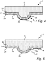
- Figs 4-5 are schematic illustrations of a cross-section of an embodiment of a compressible electrode 1 with an exposed conductor layer, wherein the stretchable conductor layer 4 is differently arranged in relation to the deformed portion 3.
- the stretchable conductor layer 4 is arranged at the deformed portion 3 such that it further extends with edge portions 4b on a flat portion 2c of the second outer surface 2b.
- the stretchable conductor layer 4 may alternatively extend only at the deformed portion 3 or at the non-deformed portion 2c.
- the compressible electrode 1 may comprise plural strips of conductor material, wherein one or more strips extend only at the deformed portion 3 and/or one or more strips extend only at the non-deformed portion 2c.
- Figs 6a-6d illustrate a method of forming the compressible electrode discussed in relation to Fig. 1 above, i.e. a compressible electrode having an exposed conductor layer 4.
- the stretchable conductor layer 4 is arranged on the second surface 2b of the stably deformable polymer layer 2 by printing a pattern, such as parallel strips 4a having a width of 5-15 mm and a pitch of 10 mm of stretchable conductors on a thin, flat stably deformable polymer substrate 2 of thermoplastic poly-urethane.
- thermoforming tool 6 having a shape with indentation 6a equal to the shape of the desired protrusion 3b of the deformed portion of the compressible electrode 1 is provided and, as illustrated in Fig. 6b , a thermoforming process is performed for permanently deforming the thermoplastic polymer 2 and the stretchable conductor layer 4 at the position of the indentation 6a of the forming tool 6.
- the thermoforming process is performed by heating the stably deformable polymer layer 2 and the stretchable conductor layer 4 and forming the deformed portion 3 using a forming tool 6 having an indentation 6a corresponding to the shape of the deformed portion 3.
- thermoformed structure i.e. in this case the formed indentation 3a in the first outer surface 2a of the stably deformable polymer layer 2
- an elastic material 5 such as a polyurethane gel
- the flat portions 2c of the first outer surface 2a of the stably deformable polymer layer 2 are also covered with the elastic material 5, before the compressible electrode is released from the forming tool 6, as illustrated in Fig. 6d .
- thermoformed stably deformable polymer layer 2 and the stretchable conductor layer 4 may thus remain in the forming tool 6 when depositing the elastic material 5. As an alternative, these may be removed from the forming tool 6 and be transferred to any other support structure or carrier before deposition of the elastic material.
- the stably deformable polymer layer 2 and the stretchable polymer 4 may be turned upside down as compared to Fig. 6a , i.e. such that the thermoplastic polymer layer 2 faces the indentation 6a of the forming tool 6.
- the method 100 thus comprises the steps of arranging 101 at least one stretchable conductor layer 4 on a first outer surface 2a or second outer surface 2b of a stably deformable polymer layer 2; forming 102 at least one deformed portion 3 as an indentation 3a in the first outer surface 2a and a corresponding protrusion 3b in the second outer surface 2b of the stably deformable polymer layer 2 at the position of the at least one stretchable conductor layer 4 thereby stably deforming the stably deformable polymer layer 2 and the at least one stretchable conductor layer 4; and filling 103 the indentation 3a with an elastic material 5.
- Figs. 7a and 7b illustrate an embodiment of a capacitive pressure sensor 10 in which the compressible electrode 1 illustrated in Fig. 1 is arranged.
- the pressure sensor further comprises an additional electrode 7, in this case illustrated as a lower flat electrode.
- the additional electrode 7 may for example be a flat rigid or a flexible conductor.
- the second surface 2b of the stably deformable polymer layer 2 of the compressible electrode 1 is arranged such that it faces the additional electrode 7.
- the stretchable conductor layer 4 is arranged on this second outer surface 2b, there is an additional dielectric layer 8 arranged on top of the additional electrode 7 such that the dielectric of the capacitive pressure sensor comprises both the air 9 and the additional dielectric layer 8.
- the additional dielectric layer is thus used so as to avoid a short circuit between the two electrodes of the pressure sensor.
- the additional dielectric layer 8 may be applied using e.g. spin coating or lamination.
- the additional dielectric layer 8 can be an ultrathin layer, such as between 1 and 10 ⁇ m, such as between 1 and 5 ⁇ m thick. This will result in a capacitive pressure sensor 10 with high capacitance values per unit area.
- the deformed portion abuts the additional dielectric 8 arranged on the additional electrode 7.
- the actual capacitor dielectric between the two electrodes 1, 7 of the pressure sensor 10 thus consists of air 9 and the applied additional dielectric layer 8.
- a measured capacitance of the capacitive pressure sensor 10 may thus be used as a measure of the pressure force.
- Fig. 5b is an idealised representation of a fully compressed compressible electrode 1, i.e. in which the deformed portion 3 has been fully compressed, by the pressure force P applied substantially in parallel to the normal of the stably deformable polymer layer 2 of the pressure sensor 1 and the flat additional electrode 7.
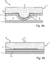
- Figs. 8a and 8b illustrate an embodiment of a capacitive pressure sensor 10 in which the compressible electrode 1 illustrated in Fig. 2 is arranged.
- This sensor 10 functions as is discussed in relation to Figs. 7a and 7b above, but a compressible electrode 1 having the stretchable conductor layer 4 arranged on the first outer surface 2a is arranged.
- the stretchable conductor layer 4 is arranged between the stably deformable polymer layer 2 and the elastic material 5. Therefore, as the deformed portion 3 is arranged so that it abuts the additional electrode 7, no additional dielectric material is needed.
- the total dielectric medium arranged between the compressible electrode 1 and the additional electrode 7 is thus the air 9.
- the second surface 2b of the thermoplastic polymer layer is pressed against the additional electrode 8.
- the force is represented by arrow "P" and is in this case directed in the direction of the normal to the stably deformable polymer layer 2.
Landscapes
- Physics & Mathematics (AREA)
- General Physics & Mathematics (AREA)
- Engineering & Computer Science (AREA)
- Power Engineering (AREA)
- Pressure Sensors (AREA)
Abstract
Description
- The present inventive concept relates to the field of compressible electrodes.
- More particularly, it relates to a compressible electrode and a capacitive pressure sensor comprising a compressible electrode.
- A basic capacitive pressure sensor consists of two electrodes with a dielectric in between the electrodes. By applying force/pressure on the sensor, either the dielectric, and/or at least one of the electrodes are deformed, resulting in a measurable change of capacitance value of the sensor. For achieving a high sensitivity and high values of capacitance per unit area, compressible electrodes are usually used in the sensors.
- A compressible electrode may consist of an electrically non-conductive, deformable polymer with electrically conductive fillers making the deformable polymer electrically conductive, resulting in an electrically conductive polymer composite. The compressible electrode may also, as an alternative, be a non-conductive polymer coated with a conductive layer. An example of a compressible electrode is disclosed in
US 9,752,940 - However, there are several technical problems associated with existing solutions First of all, adding conductive fillers to produce an electrically conductive polymer composite may increase the hardness of the deformable polymer and thereby reduce the sensitivity of the whole compressible electrode. Secondly, when forming the compressible electrode as a conductive coating on a non-conductive polymer, there are generally requirements that need to be fulfilled but, in reality, may prove to be incompatible with each other. As an example, in order to have a sufficient sensitivity of the electrode, the non-conductive polymer used should be soft, e.g. a silicone rubber material or a gel, but problems often arise with adhesion capacity of the conductive coating to such soft polymers. Further, the adhesion process itself may need to be performed on non-flat surfaces that are not standard within the art.
- Thus, there is a need in the art for improved compressible electrodes that may be used in capacitive pressure sensors.
- It is an object of the invention to at least partly overcome one or more limitations of the prior art. In particular, it is an object to provide a compressible electrode and a capacitive pressure sensor that are both sensitive and easy to transfer to a production environment.
- As a first aspect of the invention, there is provided a compressible electrode comprising a stably deformable polymer layer comprising a first outer surface, a second outer surface, at least one deformed portion formed as at least one indentation in the first outer surface and at least one corresponding protrusion in the second outer surface, and at least one non-deformed portion.
- The compressible electrode further comprises at least one stretchable conductor layer arranged on or within the stably deformable polymer layer at the at least one deformed portion and/or at the at least one non-deformed portion; and wherein the stably deformable polymer layer is stably deformed stably deformed at the at least one deformed portion.
- The compressible electrode further comprises an elastic material arranged on the first outer surface such that the elastic material fills the at least one indentation of said at least one deformed portion.
- The stably deformable polymer layer may be in the form of a sheet or layer and may form a substrate or a carrier for the stretchable conductor layer during e.g. deposition and printing of the stretchable conductor layer onto the stably deformable polymer layer. However, as an alternative, the stretchable conductor layer may be arranged within the stably deformable polymer layer, i.e. be embedded in the stably deformable polymer layer.
- The stably deformable polymer layer may be any polymer layer that may be deformed into a stable, deformed shape. The stably deformable polymer layer will retain the stable, deformed shape in the absence of any external force on the stably deformable polymer layer.
- A deformation of the stably deformable polymer layer may be achieved by subjecting the stably deformable polymer layer to external conditions causing the deformation. For instance, the deformation may be caused by one or more of heating, applying a pressure or a vacuum on the stably deformable polymer layer. The deformation may be achieved by a thermoforming process, which may include heating, shaping and cooling of the stably deformable polymer layer, for bringing the stably deformable polymer layer into a deformed shape, which may or may not be a predetermined shape of the stably deformable polymer layer. Thus, the stably deformable polymer layer may be a thermoformable polymer layer, such as formed by a thermoset material or a thermoplastic material.
- According to an embodiment, the stably deformable polymer layer may be configured to be irreversibly deformed into a deformed shape. For instance, the stably deformable polymer layer may be formed by a thermoset material, which may be irreversibly deformed into a deformed shape by curing, such as heating.
- According to another embodiment, the stably deformable polymer layer may be configured to be reversibly deformed, such that the stably deformable polymer layer may be deformed and, upon being subjected to a sufficient external force, the stably deformable polymer layer may be re-shaped. For instance, the stably deformable polymer layer may be formed by a thermoplastic material, which may be deformed into a deformed shape by e.g. a thermoforming process and which may be re-shaped by again heating the thermoplastic material above its melting temperature, reshaping it, followed by cooling it down below its melting temperature. The stably deformable polymer layer may alternatively be formed by a shape memory polymer, which may be deformed from a primary shape into a secondary predetermined deformed shape by heating it above its glass transition temperature and deforming it into said secondary predetermined deformed shape, followed by cooling it down below its glass transition temperature, and may be further returned into its primary shape, e.g. by heating the shape memory polymer above its glass transition temperature.
- The stably deformable polymer layer may comprise a thermoplastic polymer, or may consist of a thermoplastic polymer, which becomes mouldable at a certain elevated temperature and then solidifies upon cooling. Thus, the thermoplastic polymer allows for being moulded in a wide range of shapes, then be resoftened and be moulded again, as explained above.
- The stably deformable polymer layer comprises a first outer surface and a second outer surface. At least the second outer surface may function as an outer surface of the compressible electrode.
- The stably deformable polymer layer further comprises at least one deformed portion, which refers to a structure of the stably deformable polymer layer that has been deformed during the manufacturing process. Further, the at least one deformed portion has a shape or structure such that it may be macroscopically deformed or compressed upon a force acting against the normal of the first or second outer surface of the stably deformable polymer layer. Accordingly, a deformed portion may be arranged to be compressed upon a compression force applied parallel to the normal of the first outer surface.
- The deformed portion may be in the form of a "micro bump" defined by an indentation in one of the outer surfaces and a corresponding protrusion in the other. The stably deformable polymer layer may thus be a flat surface having one or several of such deformed portions, such as one or several micro bumps in the flat surface. Consequently, the stably deformable polymer layer comprises at least one deformed portion and at least one non-deformed portion. Such non-deformed portions may be flat or substantially flat portions between deformed portions. A non-deformed portion refers to a portion that has not been stably deformed during the manufacturing process and may thus retain its non-deformed shape, such as retaining a flat shape. The non-deformed portion may macroscopically be compressed to a lesser degree compared to a deformed portion. Consequently, the deformed portions and the non-deformed portions may comprise the same stably deformable polymer layer, but the deformed portion may be macroscopically compressed to a larger extent as a response to a compression force. There is further at least one stretchable conductor layer, which is an electrically conductive layer, arranged at the deformed portion or portions and/or at the non-deformed portion or portions of the stably deformable polymer layer. Thus, the at least one stretchable conductor layer may be arranged on an outer surface of the stably deformable polymer layer. As an alternative, the stretchable conductor layer may be arranged within the stably deformable polymer layer at the deformed portion and/or at the non-deformed portion, such as within the indentation or on the protrusion of the deformed portion. The stretchable conductor layer may further extend such that it is arranged at several deformed portions and non-deformed portions.
- According to an embodiment, the at least one stretchable conductor layer may be arranged on or within the stably deformable polymer layer at least at the at least one deformed portion. This implies that the at least one stretchable conductor layer is deformed with the stably deformable polymer layer at the at least one deformed portion. According to an embodiment, the at least one stretchable conductor layer is arranged only at the at least one deformed portion. However, according to another embodiment, the at least one stretchable conductor layer is arranged to extend both at the at least one deformed portion and at the non-deformed portion.
- According to yet another embodiment, the at least one stretchable conductor layer is arranged only at the at least one non-deformed portion. This implies that the at least one stretchable conductor layer will not be deformed with the stably deformable polymer layer at the at least one deformed portion.
- The stretchable conductor layer may be a single layer that is patterned as multiple parallel running strips. The pattern may be applied by printing of the conductor through a patterned mask. The conductor, and thus the conductor layer, may comprise conductive fillers in a (stretchable) binder resin.
- At the deformed portion, the stably deformable polymer layer is stably deformed, meaning that the stably deformable polymer layer has been loaded beyond its elastic limits, e.g. in a thermoforming process, such that it does not return to its original shape and size in the absence of external forces and/or heating. If the at least one stretchable conductor layer is arranged at the at least one deformed portion, the at least one stretchable conductor layer is also stably deformed at the deformed portion. The at least one stretchable conductor layer may also be loaded beyond its elastic limits, e.g. in a thermoforming process, such that it does not return to its original shape and size in the absence of external forces and/or heating.
- The deformed portion may have a rounded shape. As an example, the protrusion of deformed portion may have a rounded shape, such as substantially a half-spherical shape. However, other shapes are also possible, such as a shape in which the protrusion forms a tip as seen in a cross-section of the deformed portion. According to other embodiments, the protrusion may be configured to be tapered with a gradually decreasing width. For instance, the protrusion may have a truncated pyramidal overall shape, such as a circular truncated conical shape or a four-sided truncated pyramidal shape.
- There is further an elastic material arranged or deposited within the indentation of the deformed portion. The elastic material may be a hyperelastic material. As an example, the elastic material may be a soft elastic material, such as a material having a Young's modulus in the range 0 to 500 MPa, preferably a Young's modulus in the range of 0 to 100 MPa, and more preferably a Young's modulus in the range of 0 to 25 MPa. The elastic material may have an elastic hysteresis in the range of 0-40%, preferably smaller than 20%. The elastic material may have a shore OO hardness in the range of 0-90, preferably in the range of 20-40.
- The elastic material may be deposited solely within the indentation or as a layer covering also the non-deformed portions of the first outer surface of the stably deformable polymer layer. Thus, the elastic material may be deposited as a layer over the first outer surface of the stably deformable polymer layer so that the elastic material fills the indentations.
- The elastic material may have a thickness that is several times larger than the thickness of the stably deformable polymer layer.
- The first aspect of the invention is based on the insight that having a compressible electrode comprising two different materials, i.e. both a stably deformable polymer layer and an elastic material, instead of a single polymer layer as in the prior art, all required functionalities may be achieved, thus avoiding incompatible functionalities of prior art solutions. The stably deformable polymer layer forms a convenient substrate for the stretchable conductor layer or sheet, allowing deposition by e.g. printing of the conductor with good adhesion of the electrically conductive material to the stably deformable polymer layer. The deposition may be performed on a flat stably deformable polymer layer, i.e. on a flat substrate, which allows to apply a mass-production friendly technique. The shape of the deformed portion (indentation and protrusion) may then subsequently be obtained e.g. by thermoforming the flat stably deformable polymer layer, together with the deposited stretchable conductor layer if the stretchable conductor layer is arranged at the deformed portion, to a non-flat shape, thereby forming at least one deformed portion.
- The elastic material may be arranged on the electrode so that the mechanical stability and behaviour of the complete electrode is primarily determined by this elastic material. Thus, the elastic material may be arranged so that the complete electrode behaves in mainly an elastic manner; i.e. returns perfectly without any plastic deformation to its initial state after applying and releasing a force to the electrode, even repeatedly. Thus, the first aspect of the invention provides a compressible electrode having low drift or creep over time. Since the stretchable conductor layer is arranged on the stably deformable polymer layer, the type of elastic material may be chosen more freely compared to conventional compressible electrodes. As an example, the softness of the elastic material may be chosen more freely, e.g. from soft gel materials, so that high deformation under low force, and thus high sensitivity, may be obtained.
- In embodiments of the first aspect, the at least one stretchable conductor layer comprises stretchable silver ink. The stretchable conductor layer may also consist of intrinsically stretchable conductive polymers like such as PEDOT, thin-film or PCB (Printed Circuit Board) type metal conductors, such as Cu or Au. Further, the stretchable conductor layer may be patterned as meanders, spirals, etc., which deform, e.g. elongate or compress under an applied force.
- In embodiments of the first aspect, the at least one stretchable conductor layer is arranged on the first outer surface of the stably deformable polymer layer. Consequently, the compressible electrode may have the stretchable conductor layer or stretchable conductor layers embedded between the thermoplastic polymer layer and the elastic material.
- As an alternative, the stretchable conductor layer may be exposed. Thus, in embodiments of the first aspect, the at least one stretchable conductor layer is arranged on the second outer surface of the stably deformable polymer layer.
- In embodiments of the first aspect, the at least one stretchable conductor layer comprises a plurality of strips of electrically conductive material.
- The strips may be arranged such that one strip covers more than one deformed portion. The strips may have a width of e.g. 5-20 mm, such as between 6-15 mm, such as between 6-10 mm. The strips may be arranged at a pitch of 5-20 mm, such as about 10 mm.
- In embodiments of the first aspect, the at least one stretchable conductor layer is arranged at said at least one deformed portion such that it further extends on said at least one non-deformed portion of the first and/or second outer surface.
- In embodiments, the stably deformable polymer layer may be a flat layer having at least one deformed portion, and the stretchable conductor layer may be arranged so that it also extends from the at least one deformed portion onto a flat portion of the first or second outer surface of the stably deformable polymer layer. Thus, in embodiments, the stretchable conductor layer is also arranged at a non-deformed, flat portion of the compressible electrode.
- As an example, a stretchable conductor layer may be arranged such that it covers more than one deformed portion, such as at least two, such as at least three deformed portions.
- Accordingly, in embodiments, the stably deformable polymer layer comprises a plurality of deformed portions, and wherein at least one stretchable conductor layer is arranged on or within said stably deformable polymer layer at said plurality of deformed portions.
- Thus, a single stretchable conductor layer or strip may be arranged such that it covers several deformed portions of the stably deformable polymer layer.
- In embodiments of the first aspect, the elastic material has a volume that is larger than the volume of the stably deformable polymer layer. As an example, the elastic material may have a volume that is at least two times, preferably at least five times, more preferably at least ten times and most preferably at least twenty times larger than the volume of the stably deformable polymer layer.
- The volumes of the elastic material and the stably deformable polymer layer may be related such that the mechanical properties of the compressible electrode are primarily determined by the mechanical properties of the elastic material.
- The functional behaviour, such as hysteresis and hardness, of the electrode may be determined by material properties of the elastic material. Thus, the elastic material may be a dominant influence on the functional behaviour of the electrode. For instance, the hardness and/or the hysteresis of the electrode may be comparable or in the same range as of the elastic material.
- The elastic material may be a polymer. As an example, the elastic material may be a thermoplastic elastomer. A thermoplastic elastomer may be selected from the group consisting of thermoplastic urethanes (TPUs), styrene copolymers (styrene block copolymer, in particular styrene-ethylene-butylene-styrene block copolymer (SEBS) and/or styrene-butylene-styrene block copolymer (SBS)), thermoplastic olefins (TPOs), thermoplastic silicones and elastomeric alloys. The elastic material preferably comprises at least one thermoplastic gel material, such as a polyurethane gel, thermoplastic block copolymer gels (SEBS), PVC plastisol gels, and silicone rubbers such as PDMS (poly dimethyl siloxane).
- Moreover, the stably deformable polymer layer may comprise or consist of polyethylene, polypropylene, polyvinyl chloride, polystyrene, polyamides, polyesters or polyurethanes. As an example, the stably deformable polymer layer may be a thermoplastic polyurethane. The stably deformable polymer layer may be a shape memory polymer, such as a block polymer of polyethylene terephthalate and polyethyleneoxide.
- It should be realized that the first outer surface and the second outer surface of the stably deformable polymer layer need not necessarily be formed by the same material. For instance, the first outer surface may be a high recovery TPU and the second outer surface may be a melt adhesive TPU.
- In embodiments of the first aspect, the stably deformable polymer layer is thermoplastic polyurethane and the elastic material is a polyurethane gel.
- In embodiments of the first aspect, the thickness of the stably deformable polymer layer is less than 100 µm, such as less than 55 µm. As an example, the thickness of the stably deformable polymer layer may be between 10-100 µm, such as between 20- 60 µm, such as between 25-50 µm.
- According to another aspect of the present inventive concept there is provided a method of forming a compressible electrode comprising the steps of
- arranging at least one stretchable conductor layer on a first or second outer surface of a stably deformable polymer layer;
- forming at least one deformed portion as at least one indentation in the first outer surface and at least one corresponding protrusion in the second outer surface of the stably deformable polymer layer; thereby stably deforming the stably deformable polymer layer;
- filling the at least one indentation with an elastic material.
- This aspect may generally present the same or corresponding advantages as the former aspect. Effects and features of this second aspect are largely analogous to those described above in connection with the first aspect. Embodiments mentioned in relation to the first aspect are largely compatible with the second aspect.
- As an alternative to the first step, the method may comprise arranging the at least one stretchable conductor layer within a stably deformable polymer layer.
- The method of the second aspect may thus be used to form or produce a compressible electrode according to the first aspect as discussed herein above.
- In embodiments of the second aspect, the step of arranging the at least one stretchable conductor layer comprises printing at least one strip of a stretchable conductor layer onto the first or second surface of the stably deformable polymer layer.
- In embodiments of the second aspect, the at least one deformed portion is formed at the position of said at least one stretchable conductor layer, thereby stably deforming the stably deformable polymer layer and the at least one stretchable conductor layer.
- In embodiments of the second aspect, the step of forming at least one deformed portion comprises subjecting the stably deformable polymer layer to a thermoforming process. If the at least one deformed portion is formed at the position of said at least one stretchable conductor layer, the at least one stretchable conductor layer is also subjected to a thermoforming process.
- Thermoforming is a process where a temperature and/or a force is applied, e.g. by a temperature and force being applied at the same time or sequentially so that the to-deform-structure becomes soft enough so that it can be deformed according to the shape of e.g. a forming tool. The force may be provided by applying a pressure, such as used in compression moulding. The force may also be generated by a vacuum. When the increased temperature and/or force is removed, the structure has completely or at least partially taken the form of the forming tool.
- Thus, the step of forming may comprise raising the temperature of the stably deformable polymer layer and the at least one stretchable conductor layer such that they are pliable and extensible, and thus deformable, and then forming them in a mould to create the desired deformed portion.
- Thermoforming may comprise "vacuum forming", in which vacuum is applied only at the backside of the (porous) forming tool and "high pressure forming", in which additional high (air) pressure is applied at the front side of the forming tool.
- As an example, the thermoforming process may be performed by heating the stably deformable polymer layer, thereby forming the at least one deformed portion using a forming tool having at least one indentation corresponding to the shape of the at least one deformed portion. The forming tool thus functions as a mould for creating the deformed portion or portions in the stably deformable polymer layer. A forming tool is normally a polymer or a metal object with a surface having a shape equal to the desired final shape of the surface the thermoformed object. Moreover, the forming tool may have through holes from frontside to the backside, or is porous, so that vacuum may pull the thermoformed object to the walls of the forming tool.
- In embodiments of the second aspect, the elastic material is further formed at non-deformed portions of the first outer surface of the stably deformable polymer layer. Thus, both the indentations and the non-deformed portions of the stably deformable polymer layer may be filled with the elastic material, e.g. using a deposition process.
- In embodiments of the second aspect, the step of filling with the elastic material is performed while the stably deformable polymer layer and the at least one stretchable conductor layer is still in a forming tool used during a thermoforming process for forming the deformed portions. However, as an alternative, the stably deformable polymer layer and the at least one stretchable conductor layer may be removed from such a forming tool and e.g. transferred to another structured carrier before filling with the elastic material.
- As a third aspect of the invention, there is provided a capacitive pressure sensor comprising
- a compressible electrode according to the first aspect arranged over an additional electrode and with the second outer surface facing the additional electrode; and
- at least one dielectric medium arranged between the second outer surface and the additional electrode; and wherein
- the compressible electrode and additional electrode are arranged such that compression of the at least one deformed portion of the compressible electrode changes the capacitance of the capacitive pressure sensor.
- This aspect may generally present the same or corresponding advantages as the former aspect. Effects and features of this third aspect are largely analogous to those described above in connection with the first and second aspects. Embodiments mentioned in relation to the first and second aspects are largely compatible with the third aspect.
- The compressible electrode may thus form one electrode of the capacitive pressure sensor. The additional electrode can be a flat electrode or a compressible electrode.
- The at least one dielectric medium may comprise air. By applying a pressure in the direction of the normal of the first surface of the stably deformable polymer layer, the amount of the at least one dielectric medium, such as air, may decrease due to the compression of the deformed portion of the compressible electrode. Thus, the distance between the two electrodes, i.e. the distance between the two capacitor plates decreases and the capacitance value of the pressure sensor will increase. This change in capacitance may be measured and thus correspond to the pressure applied.
- In embodiments of the third aspect, the at least one deformed portion of the compressible electrode abuts the additional electrode, or an additional dielectric layer arranged on top of the additional electrode.
- Thus, the protrusion of the deformed portion may be arranged such that it abuts the additional electrode. As an alternative, there may be an additional dielectric layer arranged over the additional electrode, and the protrusion may abut this additional dielectric layer.
- In embodiments of the third aspect, the at least one stretchable conductor layer is arranged on the first outer surface of the stably deformable polymer layer of the compressible electrode, and wherein the at least one dielectric medium is air. Thus, the compressible electrode may have the stretchable conductor layers "embedded" between the stably deformable polymer layer and the elastic material, such that the second surface of the stably deformable polymer layer at the deformed portion abuts the additional electrode. In such case, the at least one dielectric medium may comprise air or may only consist of air.
- In further embodiments of the third aspect, the stretchable conductor layer is arranged within the stably deformable polymer layer. In such case, the at least one dielectric may also comprise air or consist only of air, i.e. there may be no additional dielectric layer arranged on the additional electrode.
- As an alternative embodiment of the third aspect, the at least one stretchable conductor layer is arranged on the second outer surface of the stably deformable polymer layer of the compressible electrode, and further wherein the sensor comprises an additional dielectric layer arranged on top of the additional electrode, such that the at least one dielectric comprises both air and the additional dielectric layer. Consequently, when the stretchable conductor layers are arranged such they are exposed, i.e. on the second outer surface of the stably deformable polymer layer, there may be an additional dielectric layer arranged over the additional electrode to avoid a short circuit between the compressible electrode and the additional electrode. Thus, in such cases, the at least one dielectric medium may comprise air and the additional dielectric layer arranged on the additional electrode.
- The additional dielectric layer may be formed e.g. by spin coating or lamination. The thickness of this additional dielectric layer may be less than 10 µm, such as between 1-5 µm.
- The above, as well as additional objects, features and advantages of the present inventive concept, will be better understood through the following illustrative and non-limiting detailed description, with reference to the appended drawings. In the drawings like reference numerals will be used for like elements unless stated otherwise.
-
Fig. 1 is a schematic illustration of a cross-section of an embodiment of a compressible electrode with an exposed conductor layer. -
Fig. 2 is a schematic illustration of a cross-section of an embodiment of a compressible electrode with an embedded conductor layer. -
Fig. 3 is a schematic illustration of a cross-section of an embodiment of a compressible electrode having a point-shaped deformed portion. -
Fig. 4 is a schematic illustration of a cross-section of another embodiment of a compressible electrode with an exposed conductor layer. -
Fig. 5 is a schematic illustration of a cross-section of yet another embodiment of a compressible electrode with an exposed conductor layer. -
Figs. 6a-6d is a schematic illustration of a method of forming the compressible electrode. -
Figs. 7a and 7b illustrate an embodiment of a capacitive pressure sensor. -
Figs. 8a and 8b illustrate an embodiment of a capacitive pressure sensor. -
Fig. 9 schematically illustrates the steps of forming a compressible electrode. -
Fig. 1 is a schematic illustration of a cross-section of an embodiment of acompressible electrode 1 with an exposed conductor layer. Thecompressible electrode 1 comprises a thin stablydeformable polymer layer 2, arranged as a sheet having micro-bumps, ordeformed portions 3. The thickness of the stablydeformable polymer layer 2 may be less than 100 µm, such as less than 55 µm, such as 25 -50 µm. - There is only one
deformed portion 3 illustrated inFig. 1 , but the stablydeformable polymer layer 2 may comprise a plurality of suchdeformed portions 3, such as at least five, such as at least ten, deformed portions. Adeformed portion 3 is formed as anindentation 3a in a firstouter surface 2a - in this case the upper outer surface - and acorresponding protrusion 3b in a secondouter surface 2b - in this case the lower outer surface- of the stably deformable polymer layer. - There is further a
stretchable conductor layer 4 arranged on the secondouter surface 2b of the stablydeformable polymer layer 2, which thereby results in a compressible electrode having an exposedconductor layer 4. Thestretchable conductor layer 4 comprises an electrically conductive material. As an example, it may comprise or consist of stretchable silver ink. Thisstretchable conductor layer 4 is arranged at the position of thedeformed portion 3. Moreover, the stablydeformable polymer layer 2 and thestretchable conductor layer 4 are stably deformed at the at least onedeformed portion 3. The stretchable conductor layer is in this example in the form of several parallel strips, but it should be realized that other forms, shapes or configurations of the stretchable conductor layer are possible. Only one strip of conductor material is illustrated inFig. 1 . This strip may however extend such that it is arranged over at least two deformed portions. Thus, thestretchable conductor layer 4 is arranged at thedeformed portion 3 such that it further extends withedge portions 4b on aflat portion 2c of the secondouter surface 2b. Theflat portion 2c is thus positioned next to thedeformed portion 3, i.e. in between twodeformed portions 3, and may thus function as a substantially non-deformed portion of theelectrode 1. This means that a pressure applied in the direction of the normal of the first 2a or second 2b outer surface of the stably deformable polymer layer will mainly result in deformation or compression of thedeformed portion 3 and not theflat surface portion 2c. - The thin stably deformable polymer layer may be of thermoplastic polyurethane, thus forms a substrate for the
stretchable conductor layer 4 and thus allows for printing or deposition of thestretchable conductor layer 4 before forming thedeformed portions 3, i.e. deposition of thestretchable conductor layer 4 on a flat surface, which is a mass-production friendly technique. The shape of the deformed portion or portions may subsequently be obtained by thermoforming the flat stablydeformable polymer layer 2 and deposited conductor material to a non-flat shape (e.g. a matrix of spherical structures). - The
compressible electrode 1 further comprises anelastic material 5 arranged on theouter surface 2a of the stablydeformable polymer layer 2 at least such that it fills at least oneindentation 3a. As illustrated inFig. 1 , theelastic material 5 may also be deposited on theflat portions 2c of the stablydeformable polymer layer 2. In this case, the elastic material has been deposited on theflat surface 2c of the stablydeformable polymer layer 2 such that it also fills theindentations 3a. - Since the stably
deformable polymer layer 2 is very thin, and the applied volume of theelastic bulk material 5 is much larger than that of the stablydeformable polymer layer 2, the mechanical behaviour and stability of thecomplete electrode 1 is primarily determined by theelastic material 5. The elastic material may have a Young's modulus in the range 0 to 500 MPa, preferably a Young's modulus in the range of 0 to 100 MPa, and more preferably a Young's modulus in the range of 0 to 25 MPa. The elastic material may have an elastic hysteresis in the range of 0-40%, preferably smaller than 20%. Further, thecomplete electrode 1 may also behave in a perfectly elastic manner, i.e. return perfectly (without any plastic deformation) to its initial state after applying and releasing force to theelectrode 1, even repeatedly. This may guarantee that theelectrode 1 has a high mechanical stability with minimal drift/creep over time. Moreover, the softness of this elastic material can be chosen freely (e.g. from the class of soft gel materials), so that high deformation under low force and thus high sensitivity can be obtained. For instance, the elastic material may have a shore OO hardness in the range of 0-90, preferably in the range of 20-40. -
Fig. 2 is a schematic illustration of a cross-section of an embodiment of acompressible electrode 1 with an embedded conductor layer. This electrode has the same arrangement as the electrode discussed in relation toFig. 1 above, but with the difference that thestretchable conductor layer 4 is arranged on the firstouter surface 2a of the stablydeformable polymer layer 2. Theelastic material 5 is thus at the position of the deformed portion at least partly deposited over thestretchable conductor layer 4. - However, the
stretchable conductor layer 4 may also be arranged within the stablydeformable polymer layer 2 at the position of the deformed portion (not illustrated inFigs. 1 or 2 ). - The
deformed portions 3, or at least theprotrusions 3b, may have a rounded form, as illustrated inFigs. 1 and 2 . As an example, theprotrusions 3b may have the form of a hemisphere. As a further example, the protrusions may have a rounded form as seen in at least one cross-section of the protrusion. Theprotrusions 3b, and the wholedeformed portions 3, may as an alternative have a tip-shaped form, as illustrated inFig. 3 . In this example, thecompressible electrode 1 is as discussed in relation toFig. 2 above, but at least onedeformed portion 3 is tip-shaped, i.e. the protrusion extends from thesecond surface 2b of the stablydeformable polymer layer 2 and converges to form atip 3c at the distance furthest away from the surface. Thedeformed portion 3 may however be tip-shaped in only one cross-section. The use of a rounded or tip-shaped deformed portion may depend on the application of the electrode. An electrode having a tip-shaped deformed portion may be more sensitive to small compression forces compared to an electrode having a rounded deformed portion. In some examples, the compressible electrode comprises both rounded and tip-shaped deformed portions. -
Figs 4-5 are schematic illustrations of a cross-section of an embodiment of acompressible electrode 1 with an exposed conductor layer, wherein thestretchable conductor layer 4 is differently arranged in relation to thedeformed portion 3. In the embodiment shown inFig. 1 , thestretchable conductor layer 4 is arranged at thedeformed portion 3 such that it further extends withedge portions 4b on aflat portion 2c of the secondouter surface 2b. However, as illustrated inFigs 4 and 5 , thestretchable conductor layer 4 may alternatively extend only at thedeformed portion 3 or at thenon-deformed portion 2c. Thecompressible electrode 1 may comprise plural strips of conductor material, wherein one or more strips extend only at thedeformed portion 3 and/or one or more strips extend only at thenon-deformed portion 2c. -
Figs 6a-6d illustrate a method of forming the compressible electrode discussed in relation toFig. 1 above, i.e. a compressible electrode having an exposedconductor layer 4. InFig. 6a , thestretchable conductor layer 4 is arranged on thesecond surface 2b of the stablydeformable polymer layer 2 by printing a pattern, such asparallel strips 4a having a width of 5-15 mm and a pitch of 10 mm of stretchable conductors on a thin, flat stablydeformable polymer substrate 2 of thermoplastic poly-urethane. Further, ametal forming tool 6 having a shape withindentation 6a equal to the shape of the desiredprotrusion 3b of the deformed portion of thecompressible electrode 1 is provided and, as illustrated inFig. 6b , a thermoforming process is performed for permanently deforming thethermoplastic polymer 2 and thestretchable conductor layer 4 at the position of theindentation 6a of the formingtool 6. Thus, the thermoforming process is performed by heating the stablydeformable polymer layer 2 and thestretchable conductor layer 4 and forming thedeformed portion 3 using a formingtool 6 having anindentation 6a corresponding to the shape of thedeformed portion 3. - As illustrated in
Fig. 6c , the thermoformed structure, i.e. in this case the formedindentation 3a in the firstouter surface 2a of the stablydeformable polymer layer 2, is filled with anelastic material 5 such as a polyurethane gel. Optionally, also theflat portions 2c of the firstouter surface 2a of the stablydeformable polymer layer 2 are also covered with theelastic material 5, before the compressible electrode is released from the formingtool 6, as illustrated inFig. 6d . - The thermoformed stably
deformable polymer layer 2 and thestretchable conductor layer 4 may thus remain in the formingtool 6 when depositing theelastic material 5. As an alternative, these may be removed from the formingtool 6 and be transferred to any other support structure or carrier before deposition of the elastic material. - In order to form a
compressible electrode 1 as illustrated inFig. 2 , i.e. with the stretchable conductor layer arranged in between the stablydeformable polymer layer 2 and theelastic material 5, the stablydeformable polymer layer 2 and thestretchable polymer 4 may be turned upside down as compared toFig. 6a , i.e. such that thethermoplastic polymer layer 2 faces theindentation 6a of the formingtool 6. - As also illustrated in the block-diagram in
Fig. 9 , themethod 100 thus comprises the steps of arranging 101 at least onestretchable conductor layer 4 on a firstouter surface 2a or secondouter surface 2b of a stablydeformable polymer layer 2; forming 102 at least onedeformed portion 3 as anindentation 3a in the firstouter surface 2a and acorresponding protrusion 3b in the secondouter surface 2b of the stablydeformable polymer layer 2 at the position of the at least onestretchable conductor layer 4 thereby stably deforming the stablydeformable polymer layer 2 and the at least onestretchable conductor layer 4; and filling 103 theindentation 3a with anelastic material 5. -
Figs. 7a and 7b illustrate an embodiment of acapacitive pressure sensor 10 in which thecompressible electrode 1 illustrated inFig. 1 is arranged. The pressure sensor further comprises anadditional electrode 7, in this case illustrated as a lower flat electrode. Theadditional electrode 7 may for example be a flat rigid or a flexible conductor. In between thecompressible electrode 1 and theadditional electrode 7, there is adielectric medium 9 in the form of air. Thesecond surface 2b of the stablydeformable polymer layer 2 of thecompressible electrode 1 is arranged such that it faces theadditional electrode 7. Since thestretchable conductor layer 4 is arranged on this secondouter surface 2b, there is an additionaldielectric layer 8 arranged on top of theadditional electrode 7 such that the dielectric of the capacitive pressure sensor comprises both theair 9 and the additionaldielectric layer 8. The additional dielectric layer is thus used so as to avoid a short circuit between the two electrodes of the pressure sensor. The additionaldielectric layer 8 may be applied using e.g. spin coating or lamination. The additionaldielectric layer 8 can be an ultrathin layer, such as between 1 and 10 µm, such as between 1 and 5 µm thick. This will result in acapacitive pressure sensor 10 with high capacitance values per unit area. - In this embodiment, the deformed portion abuts the
additional dielectric 8 arranged on theadditional electrode 7. The actual capacitor dielectric between the twoelectrodes air 9 and the applied additionaldielectric layer 8. When a compression force is applied onto thepressure sensor 10, thedeformed portion 3 may be deformed, such as squeezed together to a form of lesser height. Therefore, the amount of air between theelectrodes compressible electrode 1, i.e. the distance between the capacitor plates (= the twoelectrodes 1,7) decreases and the capacitance value will increase. A measured capacitance of thecapacitive pressure sensor 10 may thus be used as a measure of the pressure force. - When all air is pressed out of the space between the two
electrodes dielectric layer 8.Fig. 5b is an idealised representation of a fully compressedcompressible electrode 1, i.e. in which thedeformed portion 3 has been fully compressed, by the pressure force P applied substantially in parallel to the normal of the stablydeformable polymer layer 2 of thepressure sensor 1 and the flatadditional electrode 7. -
Figs. 8a and 8b illustrate an embodiment of acapacitive pressure sensor 10 in which thecompressible electrode 1 illustrated inFig. 2 is arranged. Thissensor 10 functions as is discussed in relation toFigs. 7a and 7b above, but acompressible electrode 1 having thestretchable conductor layer 4 arranged on the firstouter surface 2a is arranged. Thus, thestretchable conductor layer 4 is arranged between the stablydeformable polymer layer 2 and theelastic material 5. Therefore, as thedeformed portion 3 is arranged so that it abuts theadditional electrode 7, no additional dielectric material is needed. The total dielectric medium arranged between thecompressible electrode 1 and theadditional electrode 7 is thus theair 9. As thepressure sensor 10 is fully compressed, as illustrated inFig. 8b , thesecond surface 2b of the thermoplastic polymer layer is pressed against theadditional electrode 8. The force is represented by arrow "P" and is in this case directed in the direction of the normal to the stablydeformable polymer layer 2. - In the above the inventive concept has mainly been described with reference to a limited number of examples. However, as is readily appreciated by a person skilled in the art, other examples than the ones disclosed above are equally possible within the scope of the inventive concept, as defined by the appended claims.
Claims (15)
- A compressible electrode (1) comprising- a stably deformable polymer layer (2) comprising a first outer surface (2a), a second outer surface (2b), at least one deformed portion (3) formed as at least one indentation (3a) in said first outer surface (2a) and at least one corresponding protrusion (3b) in said second outer surface (2b), and at least one non-deformed portion (2c),- at least one stretchable conductor layer (4) arranged on or within said stably deformable polymer layer (2) at said at least one deformed portion (3) and/or at said at least one non-deformed portion (2c); and wherein said stably deformable polymer layer (2) is stably deformed at said at least one deformed portion (3); and- an elastic material (5) arranged on said first outer surface (2a) such that said elastic material (5) fills said at least one indentation (3a) of said at least one deformed portion (3).
- A compressible electrode (1) according to claim 1, wherein said at least one stretchable conductor layer (4) is arranged at least at said at least one deformed portion (3) and wherein said at least one stretchable conductor layer (4) is stably deformed at said at least one deformed portion (3).
- A compressible electrode (1) according to claim 1 or 2, wherein said at least one stretchable conductor layer (4) is arranged on said first outer surface (2a) of said stably deformable polymer layer (2).
- A compressible electrode (1) according to claim 1 or 2, wherein said at least one stretchable conductor layer (4) is arranged on said second outer surface (2b) of said stably deformable polymer layer (2).
- A compressible electrode (1) according to any previous claim, wherein the stably deformable polymer layer (2) comprises a plurality of deformed portions (3), and wherein one stretchable conductor layer (4) is arranged on or within said stably deformable polymer layer (2) at said plurality deformed portions (3).
- A compressible electrode (1) according to any previous claim, wherein said elastic material (5) has a volume that is larger than the volume of the stably deformable polymer layer (2).
- A compressible electrode (1) according to any previous claim, wherein the thickness of the stably deformable polymer layer (2) is less than 100 µm, such as less than 55 µm.
- A method (100) of forming a compressible electrode (1) comprising the steps of- arranging (101) at least one stretchable conductor layer (4) on a first (2a) or second outer surface (2b) of a stably deformable polymer layer (2) or within said stably deformable polymer layer (2);- forming (102) at least one deformed portion (3) as at least one indentation (3a) in said first outer surface (2a) and at least one corresponding protrusion in said second outer surface (2b) of the stably deformable polymer layer (2); thereby stably deforming the stably deformable polymer layer (2);- filling (103) said at least one indentation (3a) with an elastic material (5).
- A method according to claim 8, wherein said forming (103) at least one deformed portion (3) comprises subjecting the stably deformable polymer layer (2) to a thermoforming process.
- A method according to claim 9, wherein said thermoforming process is performed by heating said stably deformable polymer layer (2), thereby forming said at least one deformed portion (3) using a forming tool (6) having at least one indentation (6a) corresponding to the shape of the at least one deformed portion (3).
- A method according to any one of claims 8-10, wherein the elastic material (5) is further formed at non-deformed portions of the first (2a) or second (2b) outer surface of the stably deformable polymer layer (2).
- A capacitive pressure (10) sensor comprisinga compressible electrode (1) according to any one of claims 1-7 arranged over an additional electrode (7) and with the second outer surface (2b) facing said additional electrode (7); andat least one dielectric medium (9, 8) arranged between said second outer surface (2b) and said additional electrode (7); and whereinthe compressible electrode (1) and additional electrode (7) are arranged such that compression of the at least one deformed portion (3) of the compressible electrode (1) changes the capacitance of the capacitive pressure sensor (1).
- A capacitive pressure sensor (10) according to claim 12, wherein said at least one deformed portion (3) of the compressible electrode (1) abuts said additional electrode (7) or an additional dielectric layer (8) arranged on top of said additional electrode (7).
- A capacitive pressure sensor (10) according to claim 12 or 13, wherein the at least one stretchable conductor layer (4) is arranged on the first outer surface (2a) of said stably deformable polymer layer (2) of the compressible electrode (1), and wherein the at least one dielectric medium (9) is air.
- A capacitive pressure sensor (10) according to claim 12 or 13, wherein the at least one stretchable conductor layer (4) is arranged on the second outer surface (2b) of said stably deformable polymer layer (2) of the compressible electrode (1), and further wherein the said sensor (10) comprises an additional dielectric layer (8) arranged on top of said additional electrode (7), such that the at least one dielectric comprises both air (9) and said additional dielectric layer (8).
Priority Applications (4)
| Application Number | Priority Date | Filing Date | Title |
|---|---|---|---|
| EP20177428.8A EP3916371A1 (en) | 2020-05-29 | 2020-05-29 | A compressible electrode |
| EP21728892.7A EP4158295B1 (en) | 2020-05-29 | 2021-05-26 | Capacitive pressure sensor with a compressible electrode |
| PCT/EP2021/063989 WO2021239784A1 (en) | 2020-05-29 | 2021-05-26 | A compressible electrode |
| US17/997,898 US12399071B2 (en) | 2020-05-29 | 2021-05-26 | Compressible electrode |
Applications Claiming Priority (1)
| Application Number | Priority Date | Filing Date | Title |
|---|---|---|---|
| EP20177428.8A EP3916371A1 (en) | 2020-05-29 | 2020-05-29 | A compressible electrode |
Publications (1)
| Publication Number | Publication Date |
|---|---|
| EP3916371A1 true EP3916371A1 (en) | 2021-12-01 |
Family
ID=71094073
Family Applications (2)
| Application Number | Title | Priority Date | Filing Date |
|---|---|---|---|
| EP20177428.8A Withdrawn EP3916371A1 (en) | 2020-05-29 | 2020-05-29 | A compressible electrode |
| EP21728892.7A Active EP4158295B1 (en) | 2020-05-29 | 2021-05-26 | Capacitive pressure sensor with a compressible electrode |
Family Applications After (1)
| Application Number | Title | Priority Date | Filing Date |
|---|---|---|---|
| EP21728892.7A Active EP4158295B1 (en) | 2020-05-29 | 2021-05-26 | Capacitive pressure sensor with a compressible electrode |
Country Status (3)
| Country | Link |
|---|---|
| US (1) | US12399071B2 (en) |
| EP (2) | EP3916371A1 (en) |
| WO (1) | WO2021239784A1 (en) |
Families Citing this family (3)
| Publication number | Priority date | Publication date | Assignee | Title |
|---|---|---|---|---|
| WO2022250939A1 (en) * | 2021-05-27 | 2022-12-01 | The University Of Chicago | Strain-insensitive soft pressure sensor and method of measuring pressure |
| CN118891500A (en) * | 2022-03-24 | 2024-11-01 | 松下知识产权经营株式会社 | Load sensor |
| US20250260400A1 (en) * | 2022-04-21 | 2025-08-14 | Panasonic Intellectual Property Management Co., Ltd. | Input device |
Citations (4)
| Publication number | Priority date | Publication date | Assignee | Title |
|---|---|---|---|---|
| US20170075467A1 (en) * | 2015-09-11 | 2017-03-16 | Korea Institute Of Science And Technology | Capacitive force sensor and method for preparing the same |
| US9752940B2 (en) | 2014-12-22 | 2017-09-05 | Panasonic Intellectual Property Management Co., Ltd. | Pressure sensing element comprising electrode including protrusion having elasticity |
| US20170362083A1 (en) * | 2014-12-15 | 2017-12-21 | Seow Yuen Yee | Flexible Diposable MEMS Pressure Sensor |
| US20190305139A1 (en) * | 2018-03-29 | 2019-10-03 | Center For Advanced Soft Electronics | Thin-film transistor-based pressure sensor and method of manufacturing same |
Family Cites Families (4)
| Publication number | Priority date | Publication date | Assignee | Title |
|---|---|---|---|---|
| US20070069418A1 (en) * | 2005-09-28 | 2007-03-29 | Chih-Yuan Liao | In mold manufacturing of an object comprising a functional element |
| JP2018155711A (en) | 2017-03-21 | 2018-10-04 | 住友理工株式会社 | Sensor device |
| CN108871629A (en) | 2018-07-20 | 2018-11-23 | 浙江大学 | A kind of flexible resistive array of pressure sensors and preparation method thereof |
| CN109115376A (en) | 2018-09-28 | 2019-01-01 | 清华大学深圳研究生院 | A kind of condenser type pliable pressure sensor and preparation method thereof |
-
2020
- 2020-05-29 EP EP20177428.8A patent/EP3916371A1/en not_active Withdrawn
-
2021
- 2021-05-26 WO PCT/EP2021/063989 patent/WO2021239784A1/en not_active Ceased
- 2021-05-26 US US17/997,898 patent/US12399071B2/en active Active
- 2021-05-26 EP EP21728892.7A patent/EP4158295B1/en active Active
Patent Citations (4)
| Publication number | Priority date | Publication date | Assignee | Title |
|---|---|---|---|---|
| US20170362083A1 (en) * | 2014-12-15 | 2017-12-21 | Seow Yuen Yee | Flexible Diposable MEMS Pressure Sensor |
| US9752940B2 (en) | 2014-12-22 | 2017-09-05 | Panasonic Intellectual Property Management Co., Ltd. | Pressure sensing element comprising electrode including protrusion having elasticity |
| US20170075467A1 (en) * | 2015-09-11 | 2017-03-16 | Korea Institute Of Science And Technology | Capacitive force sensor and method for preparing the same |
| US20190305139A1 (en) * | 2018-03-29 | 2019-10-03 | Center For Advanced Soft Electronics | Thin-film transistor-based pressure sensor and method of manufacturing same |
Also Published As
| Publication number | Publication date |
|---|---|
| US12399071B2 (en) | 2025-08-26 |
| US20230175899A1 (en) | 2023-06-08 |
| EP4158295A1 (en) | 2023-04-05 |
| EP4158295B1 (en) | 2026-05-06 |
| WO2021239784A1 (en) | 2021-12-02 |
Similar Documents
| Publication | Publication Date | Title |
|---|---|---|
| CN113711000B (en) | Pressure Sensors | |
| CN100516797C (en) | Pressure sensor comprising an elastic sensor layer with a microstructured surface | |
| JP6643647B2 (en) | Pressure sensitive element | |
| EP4170309B1 (en) | Electrostatic capacitance detection device capable of calculating shear force | |
| JP6643629B2 (en) | Pressure sensitive element | |
| CN110763378A (en) | A wearable flexible tactile force sensor | |
| KR20190075827A (en) | Method for manufacturing a strain gauge device, a strain gauge device, and the use of the device | |
| EP4158295B1 (en) | Capacitive pressure sensor with a compressible electrode | |
| KR102423014B1 (en) | High sensitivity pressure sensor and its manufacturing method | |
| KR20170126302A (en) | Pressure sensor device and method for fabricaing the pressure sensor device | |
| CN105992938A (en) | Input device and input device production method | |
| CN101088134B (en) | Adhesive membrane for force switches and sensors | |
| CN113386158B (en) | Full-printing bionic super-sensing flexible robot skin | |
| Albrecht et al. | Screen-printed capacitive pressure sensors with high sensitivity and accuracy on flexible substrates | |
| EP1968360A1 (en) | Method for manufacturing flexible printed circuitry | |
| US9057651B2 (en) | Device forming a pressure sensor, method for producing such a sensor and application in the production of a touch screen | |
| JP2020071061A (en) | Elastic body and pressure sensitive element | |
| DK181377B1 (en) | Tactile sensor, matrix of tactile sensors, and methods for producing the same | |
| KR20230116676A (en) | Capacitive pressure sensor | |
| KR102463884B1 (en) | Stretchable substrate and manufacturing method thereof | |
| JP2016218560A (en) | Capacitance type three-dimensional sensor and manufacturing method thereof | |
| EP4713647A1 (en) | Pressure distribution sensing device | |
| JP3644657B2 (en) | Resin dome spring mold and method of manufacturing resin dome spring using the same | |
| JP2020193853A (en) | Contact point sheet deformation member and pressure sensitive sensor using the same, and pressure sensitive sensor unit | |
| JP2026516363A (en) | Pressure distribution sensing device |
Legal Events
| Date | Code | Title | Description |
|---|---|---|---|
| PUAI | Public reference made under article 153(3) epc to a published international application that has entered the european phase |
Free format text: ORIGINAL CODE: 0009012 |
|
| STAA | Information on the status of an ep patent application or granted ep patent |
Free format text: STATUS: THE APPLICATION HAS BEEN PUBLISHED |
|
| AK | Designated contracting states |
Kind code of ref document: A1 Designated state(s): AL AT BE BG CH CY CZ DE DK EE ES FI FR GB GR HR HU IE IS IT LI LT LU LV MC MK MT NL NO PL PT RO RS SE SI SK SM TR |
|
| B565 | Issuance of search results under rule 164(2) epc |
Effective date: 20201124 |
|
| STAA | Information on the status of an ep patent application or granted ep patent |
Free format text: STATUS: THE APPLICATION IS DEEMED TO BE WITHDRAWN |
|
| 18D | Application deemed to be withdrawn |
Effective date: 20220602 |
|
| RAP1 | Party data changed (applicant data changed or rights of an application transferred) |
Owner name: RECTICEL ENGINEERED FOAMS BELGIUM Owner name: UNIVERSITEIT GENT Owner name: IMEC VZW |