EP3916327A1 - Front panel assembly of drawer of refrigerator, drawer of refrigerator, and refrigerator - Google Patents
Front panel assembly of drawer of refrigerator, drawer of refrigerator, and refrigerator Download PDFInfo
- Publication number
- EP3916327A1 EP3916327A1 EP19919346.7A EP19919346A EP3916327A1 EP 3916327 A1 EP3916327 A1 EP 3916327A1 EP 19919346 A EP19919346 A EP 19919346A EP 3916327 A1 EP3916327 A1 EP 3916327A1
- Authority
- EP
- European Patent Office
- Prior art keywords
- light
- front panel
- drawer
- panel assembly
- plate
- Prior art date
- Legal status (The legal status is an assumption and is not a legal conclusion. Google has not performed a legal analysis and makes no representation as to the accuracy of the status listed.)
- Granted
Links
Images








Classifications
-
- F—MECHANICAL ENGINEERING; LIGHTING; HEATING; WEAPONS; BLASTING
- F25—REFRIGERATION OR COOLING; COMBINED HEATING AND REFRIGERATION SYSTEMS; HEAT PUMP SYSTEMS; MANUFACTURE OR STORAGE OF ICE; LIQUEFACTION SOLIDIFICATION OF GASES
- F25D—REFRIGERATORS; COLD ROOMS; ICE-BOXES; COOLING OR FREEZING APPARATUS NOT OTHERWISE PROVIDED FOR
- F25D25/00—Charging, supporting, and discharging the articles to be cooled
- F25D25/02—Charging, supporting, and discharging the articles to be cooled by shelves
- F25D25/024—Slidable shelves
- F25D25/025—Drawers
-
- F—MECHANICAL ENGINEERING; LIGHTING; HEATING; WEAPONS; BLASTING
- F21—LIGHTING
- F21V—FUNCTIONAL FEATURES OR DETAILS OF LIGHTING DEVICES OR SYSTEMS THEREOF; STRUCTURAL COMBINATIONS OF LIGHTING DEVICES WITH OTHER ARTICLES, NOT OTHERWISE PROVIDED FOR
- F21V11/00—Screens not covered by groups F21V1/00, F21V3/00, F21V7/00 or F21V9/00
- F21V11/16—Screens not covered by groups F21V1/00, F21V3/00, F21V7/00 or F21V9/00 using sheets without apertures, e.g. fixed
-
- F—MECHANICAL ENGINEERING; LIGHTING; HEATING; WEAPONS; BLASTING
- F21—LIGHTING
- F21V—FUNCTIONAL FEATURES OR DETAILS OF LIGHTING DEVICES OR SYSTEMS THEREOF; STRUCTURAL COMBINATIONS OF LIGHTING DEVICES WITH OTHER ARTICLES, NOT OTHERWISE PROVIDED FOR
- F21V23/00—Arrangement of electric circuit elements in or on lighting devices
- F21V23/001—Arrangement of electric circuit elements in or on lighting devices the elements being electrical wires or cables
- F21V23/002—Arrangements of cables or conductors inside a lighting device, e.g. means for guiding along parts of the housing or in a pivoting arm
-
- F—MECHANICAL ENGINEERING; LIGHTING; HEATING; WEAPONS; BLASTING
- F21—LIGHTING
- F21V—FUNCTIONAL FEATURES OR DETAILS OF LIGHTING DEVICES OR SYSTEMS THEREOF; STRUCTURAL COMBINATIONS OF LIGHTING DEVICES WITH OTHER ARTICLES, NOT OTHERWISE PROVIDED FOR
- F21V33/00—Structural combinations of lighting devices with other articles, not otherwise provided for
- F21V33/0004—Personal or domestic articles
- F21V33/0044—Household appliances, e.g. washing machines or vacuum cleaners
-
- F—MECHANICAL ENGINEERING; LIGHTING; HEATING; WEAPONS; BLASTING
- F25—REFRIGERATION OR COOLING; COMBINED HEATING AND REFRIGERATION SYSTEMS; HEAT PUMP SYSTEMS; MANUFACTURE OR STORAGE OF ICE; LIQUEFACTION SOLIDIFICATION OF GASES
- F25D—REFRIGERATORS; COLD ROOMS; ICE-BOXES; COOLING OR FREEZING APPARATUS NOT OTHERWISE PROVIDED FOR
- F25D27/00—Lighting arrangements
-
- G—PHYSICS
- G02—OPTICS
- G02B—OPTICAL ELEMENTS, SYSTEMS OR APPARATUS
- G02B6/00—Light guides; Structural details of arrangements comprising light guides and other optical elements, e.g. couplings
- G02B6/0001—Light guides; Structural details of arrangements comprising light guides and other optical elements, e.g. couplings specially adapted for lighting devices or systems
- G02B6/0011—Light guides; Structural details of arrangements comprising light guides and other optical elements, e.g. couplings specially adapted for lighting devices or systems the light guides being planar or of plate-like form
- G02B6/0033—Means for improving the coupling-out of light from the light guide
- G02B6/005—Means for improving the coupling-out of light from the light guide provided by one optical element, or plurality thereof, placed on the light output side of the light guide
- G02B6/0055—Reflecting element, sheet or layer
-
- G—PHYSICS
- G02—OPTICS
- G02B—OPTICAL ELEMENTS, SYSTEMS OR APPARATUS
- G02B6/00—Light guides; Structural details of arrangements comprising light guides and other optical elements, e.g. couplings
- G02B6/0001—Light guides; Structural details of arrangements comprising light guides and other optical elements, e.g. couplings specially adapted for lighting devices or systems
- G02B6/0011—Light guides; Structural details of arrangements comprising light guides and other optical elements, e.g. couplings specially adapted for lighting devices or systems the light guides being planar or of plate-like form
- G02B6/0081—Mechanical or electrical aspects of the light guide and light source in the lighting device peculiar to the adaptation to planar light guides, e.g. concerning packaging
- G02B6/0085—Means for removing heat created by the light source from the package
-
- G—PHYSICS
- G02—OPTICS
- G02B—OPTICAL ELEMENTS, SYSTEMS OR APPARATUS
- G02B6/00—Light guides; Structural details of arrangements comprising light guides and other optical elements, e.g. couplings
- G02B6/0001—Light guides; Structural details of arrangements comprising light guides and other optical elements, e.g. couplings specially adapted for lighting devices or systems
- G02B6/0011—Light guides; Structural details of arrangements comprising light guides and other optical elements, e.g. couplings specially adapted for lighting devices or systems the light guides being planar or of plate-like form
- G02B6/0081—Mechanical or electrical aspects of the light guide and light source in the lighting device peculiar to the adaptation to planar light guides, e.g. concerning packaging
- G02B6/0086—Positioning aspects
- G02B6/0088—Positioning aspects of the light guide or other optical sheets in the package
-
- F—MECHANICAL ENGINEERING; LIGHTING; HEATING; WEAPONS; BLASTING
- F25—REFRIGERATION OR COOLING; COMBINED HEATING AND REFRIGERATION SYSTEMS; HEAT PUMP SYSTEMS; MANUFACTURE OR STORAGE OF ICE; LIQUEFACTION SOLIDIFICATION OF GASES
- F25D—REFRIGERATORS; COLD ROOMS; ICE-BOXES; COOLING OR FREEZING APPARATUS NOT OTHERWISE PROVIDED FOR
- F25D23/00—General constructional features
- F25D23/02—Doors; Covers
- F25D23/021—Sliding doors
Definitions
- the present invention relates to the technical field of freezing and refrigerating devices, in particular to a front panel assembly of a drawer of a refrigerator, a drawer of a refrigerator and a refrigerator.
- the refrigerator can keep food fresh and prolong the storage time of the food, and is a necessary household appliance. More and more refrigerators adopt a drawer type design.
- the structural improvement of the drawer of the refrigerator is mainly improvement on drawer accessories, drawer interior lighting devices and the like, for example: a roller rail is disposed at the bottom of the drawer of the refrigerator, so that the drawer can be pulled and pushed conveniently; and a lighting lamp and the like are disposed at the inner wall of the side plate of the drawer body.
- One objective of the present invention is to provide a light emitting structure of a front panel assembly of a drawer of a refrigerator.
- One further objective of the present invention is to enable the front panel assembly of the drawer to achieve a visual sense of layering and a stereoscopic effect.
- Another further objective of the present invention is to simplify an installation and replacement process of a light source of the front panel assembly of the drawer.
- the present invention provides a front panel assembly of a drawer of a refrigerator, comprising:
- the light transmitting plate is vertically disposed.
- a horizontal distance between the inclined plane from a bottom edge thereof to a top edge thereof and the light transmitting plate is gradually increased, and light vertically reaches the inclined plane downwards, and then is emitted out from the light transmitting plate after being horizontally reflected forwards by the reflector.
- the inclined plane and the light transmitting plate form an acute angle in degrees of 20°-45°.
- the front end face of the front panel body is provided with a light-proof plate and the light transmitting plate disposed up and down.
- the light guide body includes a first light guide part and a second light guide part disposed up and down.
- the first light guide part is disposed corresponding to the light-proof plate, and the light source is arranged thereon.
- the second light guide part is disposed corresponding to the light transmitting plate and is provided with a vertical surface and the inclined plane. The vertical surface is attached to the light transmitting plate, and the inclined plane and the vertical surface form an acute angle.
- the front panel assembly further includes a supporting frame disposed in the accommodating cavity, fixed to the front panel body, configured to support the light guide body and comprising a first supporting part provided with an inclined structure matched with the inclined plane.
- the reflector is a reflecting film, and is attached to a lower surface of the inclined plane and/or an upper surface of the first supporting part.
- the front panel assembly further includes a lower trim strip provided with grooves opened forwards and downwards, and fixed to the supporting frame and the front panel body.
- the lower trim strip and at least one part of a lower surface of the first supporting part jointly close an opening located in a bottom of the front panel body, and a handle part with a downward opening is formed between the lower trim strip and the first supporting part, so that the front panel assembly is pulled conveniently forwards by the handle part.
- an inclination angle of the first supporting part is 20°-45°.
- the supporting frame further includes a second supporting part disposed above the first supporting part and configured to form an accommodating space in between together with the light guide body.
- a side opening corresponding to the accommodating space is formed on a side face of the front panel body, and the light source is placed in or taken out of the accommodating space through the side opening.
- the front panel assembly further includes a light uniformizing plate disposed in the accommodating space.
- the light source is a lamp strip or a lamp panel, and light emitted by the light source vertically enters the light guide body downwards to reach the inclined plane after passing through the light uniformizing plate.
- the front panel assembly further includes a heat dissipation piece disposed in the accommodating space and configured to dissipate heat from the light source and the light uniformizing plate; wherein a light source placing area is defined among the heat dissipation piece, the light uniformizing plate and the light guide body, and the light source is disposed in the light source placing area so as to limit the light source in a front-back direction.
- the front panel assembly further includes a cabling rack disposed corresponding to the side opening and provided with a main body part and an extending part.
- a first hole for access of a cable and a second hole for access of the light source are formed in the main body part, and the extending part and the second supporting part are fixed.
- the present invention further provides a drawer of a refrigerator, including:
- the present invention further provides a refrigerator provided with the forgoing drawer of the refrigerator.
- the accommodating cavity is defined in the front panel body, the light source, the light guide body and the reflector are disposed in the accommodating cavity, and the light transmitting plate is disposed on the front end face of the front panel body, so that light emitted by the light source is transmitted by the light guide body to reach the inclined plane and then to be emitted out from the light transmitting plate after being reflected by the reflector, and light emission of the front panel assembly of the drawer of the refrigerator is realized.
- the front panel assembly of the drawer of the refrigerator of the present invention is disposed such that the light source is transmitted in the light guide body and then is emitted out after being reflected by the reflector, and the light emitting effect of the front panel assembly can be adjusted by adjusting each component of the light emitting mechanism.
- the light transmitting plate of the front panel assembly of the drawer of the refrigerator of the present invention is vertically disposed.
- the horizontal distance between the inclined plane from the bottom edge thereof to the top edge thereof and the light transmitting plate is gradually increased.
- the light vertically reaches the inclined plane downwards and then is emitted out from the light transmitting plate after being horizontally reflected forwards by the reflector.
- the front panel assembly of the drawer realizes a visual sense of layering and a stereoscopic effect by changing the longitudinal direction of a structural piece from the shallower to the deeper.
- the front panel assembly of the drawer of the refrigerator of the present invention utilizes the supporting frame provided with the inclined structure matched with the inclined plane of the light guide body to fix the light guide body, so as to ensure position stability of the light guide body, and utilizes the reflecting film for reflection, so as to realize low cost and easy assembling. Moreover, the reflecting effect of the reflecting film can be made more stable by the supporting frame.
- the accommodating space is formed between the supporting frame and the light guide body of the front panel assembly of the drawer of the refrigerator of the present invention, so that the light source is convenient to place in and take out, and the light source can be easily and conveniently installed and replaced.
- FIG. 1 is a schematic front view of a refrigerator 100 according to one embodiment of the present invention.
- FIG. 2 is a schematic perspective view of a refrigerator body 110 and a first drawer 115 of the refrigerator 100 shown in FIG. 1 .
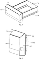
- FIG. 3 is a schematic perspective view of a drawer 115 of the refrigerator 100 shown in FIG. 1 .
- FIG. 4 is a schematic perspective view of a front panel assembly 140 shown in FIG. 3 .
- FIG. 5 is a schematic exploded view of the front panel assembly 140 shown in FIG. 4 .
- the refrigerator 100 of the embodiment of the present invention may generally include: a refrigerator body 110, a first door body 111, a second door body 112, a third door body 113, a fourth door body 114, a first drawer 115 and a second drawer 116.
- a plurality of storage compartments are defined within the refrigerator body 110.
- the first door body 111, the second door body 112, the third door body 113 and the fourth door body 114 are all rotary door bodies, and are pivotally disposed on the front side of one storage compartment through hinges respectively.
- the storage compartment corresponding to the first door body 111 and the second door body 112 is a refrigerating compartment
- the storage compartment corresponding to the third door body 113 is a temperature changing compartment or a freezing compartment
- the storage compartment corresponding to the fourth door body 114 is a freezing compartment.
- the first drawer 115 and the second drawer 116 are disposed between the first door body 111 and the third door body 113, and between the second door body 112 and the fourth door body 114, respectively, as a refrigerating compartment or a temperature changing compartment.
- the drawer 115 of the refrigerator 100 of the embodiment of the present invention includes a drawer body 120 and a front panel assembly 140.
- a storage space is defined within the drawer body 120.
- the drawer body 120 can be pulled to slide in the refrigerator body 110 through guide rails 130.
- the front panel assembly 140 is disposed in front of the drawer body 120.
- the front panel assembly 140 includes: a front panel body and a light emitting mechanism.
- the front panel body defines an accommodating cavity.
- the light emitting mechanism is disposed in the accommodating cavity and includes a light source 150, a light guide body 600 and a reflector 180.
- the light guide body 600 is disposed below the light source 150 and is provided with an inclined plane 602.
- the reflector 180 is disposed obliquely below the inclined plane 602.
- a front end face of the front panel body is provided with a light transmitting plate 202. Light emitted by the light source 150 is transmitted by the light guide body 600 to reach the inclined plane 602 and then to be emitted out from the light transmitting plate 202 after being reflected by the reflector 180.
- the accommodating cavity is defined in the front panel body, the light source 150, the light guide body 600 and the reflector 180 are disposed in the accommodating cavity, and the light transmitting plate 202 is disposed on the front end face of the front panel body, so that light emitted by the light source 150 is transmitted by the light guide body 600 to reach the inclined plane 602 and then to be emitted out from the light transmitting plate 202 after being reflected by the reflector 180, and light emission of the front panel assembly 140 is realized.
- the front panel assembly 140 of the embodiment of the present invention is disposed such that the light source 150 is transmitted in the light guide body 600 and then is emitted out after being reflected by the reflector 180, and the light emitting effect of the front panel assembly 140 can be adjusted by adjusting each component of the light emitting mechanism.
- the light transmitting plate 202 is vertically disposed.
- the horizontal distance between the inclined plane 602 from a bottom edge thereof to a top edge thereof and the light transmitting plate 202 is gradually increased.
- the light vertically reaches the inclined plane 602 downwards and then is emitted out from the light transmitting plate 202 after being horizontally reflected forwards by the reflector 180.
- the light transmitting plate 202 of the front panel assembly 140 of the embodiment of the present invention is vertically disposed.
- the horizontal distance between the inclined plane 602 from the bottom edge thereof to the top edge thereof and the light transmitting plate 202 is gradually increased (has an increasing tendency).
- FIG. 19 is a schematic effect view of the front panel assembly 140 shown in FIG. 4 .
- the inclined plane 602 and the light transmitting plate 202 form an acute angle ⁇ in degrees of 20°-45°, for example, 20°, 25°, 35° and 42°.
- the front end face of the front panel body of the embodiment of the present invention is provided with a light-proof plate 201 and the light transmitting plate 202 disposed up and down.
- the light guide body 600 includes a first light guide part 631 and a second light guide part 632 disposed up and down, wherein the first light guide part 631 is disposed corresponding to the light-proof plate 201, and the light source 150 is arranged thereon.
- the second light guide part 632 is disposed corresponding to the light transmitting plate 202 and is provided with a vertical plane and the inclined plane.
- the vertical plane is attached to the light transmitting plate 202, and the inclined plane and the vertical plane form an acute angle, wherein the inclined plane of the second light guide part 632 constitutes the inclined plane 602 of the light guide body 600, and the light vertically reaches the inclined plane of the second light guide part 632 downwards and penetrates through the vertical plane of the second light guide part 632 and the light transmitting plate 202 to be emitted out after being horizontally reflected forwards by the reflector 180.
- the front end face of the front panel assembly 140 of the embodiment of the present invention is provided with the light-proof plate 201 and the light transmitting plate 202.
- the light guide body 600 includes the first light guide part 631 and the second light guide part 632, making the boundary between a light transmitting part and a light-proof part obvious and improving the sense of layering, meanwhile ensuring that the whole area of the light transmitting part is luminous and there will be no situation where a local portion is completely grey and affects perception of users.
- the first light guide part 631 may also be configured to fix the light guide body 600.
- the front panel assembly 140 of the embodiment of the present invention further includes: a supporting frame 700, disposed in the accommodating cavity, fixed to the front panel body, and configured to support the light guide body 600.
- the supporting frame 700 includes a first supporting part 701 provided with an inclined structure, and the inclined structure of the first supporting part 701 is matched with the inclined plane 602.
- the reflector 180 is a reflecting film, located between the inclined plane 602 and the first supporting part 701 and attached to the inclined plane 602, or attached to the first supporting part 701, or is formed by carrying out surface treatment on an upper surface of the first supporting part 701.
- the front panel assembly 140 of the embodiment of the present invention utilizes the supporting frame 700 provided with the inclined structure matched with the inclined plane 602 of the light guide body 600 to fix the light guide body 600, so as to ensure position stability of the light guide body 600, and utilizes the reflecting film 180 for reflection, so as to realize low cost and easy assembling. Moreover, the reflecting effect of the reflecting film 180 can be made more stable by the supporting frame 700.
- the supporting frame 700 of the embodiment of the present invention further includes a second supporting part 702 disposed above the first supporting part 701 and configured to form an accommodating space in between together with the first light guide part 631.
- a side opening 421 corresponding to the accommodating space is formed on a side face of the front panel body, and the light source 150 is placed in or taken out of the accommodating space through the side opening 421.
- the accommodating space is formed between the supporting frame 700 and the light guide body 600 of the front panel assembly 140 of the embodiment of the present invention, so that the light source 150 is convenient to place in and take out, and the light source 150 can be easily and conveniently installed and replaced.
- the front panel assembly 140 of the embodiment of the present invention further includes a light uniformizing plate 160 disposed on the light guide body 600.
- the light source 150 is a lamp strip or a lamp panel, and light emitted by the light source 150 vertically enters the light guide body 600 downwards to reach the inclined plane 602 after passing through the light uniformizing plate 160.
- the front panel assembly 140 of the embodiment of the present invention further includes a heat dissipation piece 170 disposed in the accommodating space and configured to dissipate heat from the light source 150 and the light uniformizing plate 160, and a light source placing area 151 is defined among the heat dissipation piece 170, the light uniformizing plate 160 and the light guide body 600.
- the light source 150 is disposed in the light source placing area 151 so that the light source 150 is limited in a front-back direction.
- the front panel assembly 140 of the drawer 115 of the embodiment of the present invention is further provided with the heat dissipation piece 170 in the accommodating space to dissipate heat from the light source 150 and the light uniformizing plate 160, the situation that the service life of the light source 150 is affected due to the fact that the front panel assembly 140 is overheated is avoided, and meanwhile potential safety hazards can be avoided.
- the light source placing area 151 is defined by the heat dissipation piece 170, the light uniformizing plate 160 and the light guide body 600 together to limit the position of the light source 150 in the front-back direction.
- the front panel assembly 140 of embodiment of the present invention further includes a cabling rack 190 disposed corresponding to the side opening 421, and provided with a main body part 195 and an extending part 196.
- a first hole 191 for access of a cable and a second hole 192 for access of the light source 150 are formed in the main body part 195.
- the extending part 196 and the second supporting part 702 are fixed.
- a hook 194 is further formed on the cabling rack 190, the supporting frame 700 is provided with a notch 770, and the hook 194 fits in the notch 770.
- the front panel assembly 140 of the embodiment of the present invention further includes a lower trim strip 800 fixed to the supporting frame 700 and the front panel body.
- the lower trim strip 800 and at least one part of a lower surface of the first supporting part 701 jointly form a bottom of the front panel assembly 140.
- the lower trim strip 800 is provided with a groove 803 opened forwards and downwards. In this way, a handle part 804 with a downward opening is formed between the lower trim strip 800 and the first supporting part 701, so that the front panel assembly 140 is pulled conveniently forwards by the handle part 804.
- an inclination angle of the first supporting part 701 is 20°-45°.
- the front panel assembly 140 of the embodiment of the present invention closes the opening through the lower trim strip 800 and the supporting frame 700, and meanwhile the handle part 804 is formed in between.
- This structure is quite ingenious and facilitates a user to pull the drawer 115.
- the inclination angle of the first supporting part 701 takes into account both the light reflection and the hand feeling.
- An inclination included angle ⁇ between the first supporting part and the vertical plane is set to 20°-45°, for example, 20°, 25°, 35° and 42°.
- the front panel assembly 140 of the embodiment of the present invention includes the front panel body, a touchpad 302, a heat insulator 520, the light emitting mechanism, the supporting frame 700, the light uniformizing plate 160, the heat dissipation piece 170, the cabling rack 190 and the lower trim strip 800.
- FIG. 5 is a schematic exploded view of the front panel assembly 140 shown in FIG. 4 .
- FIG. 6 is a schematic bottom view of the front panel assembly 140 shown in FIG. 4 .
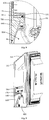
- FIG. 7 is a schematic cross-sectional view of the front panel assembly 140 shown in FIG. 6 .
- FIG. 8 is a schematic partial enlarged view of the front panel assembly 140 shown in FIG. 7 .
- FIG. 9 is a schematic perspective view of some assemblies of the front panel assembly 140 shown in FIG. 4 .
- FIG. 10 is another schematic perspective view of some assemblies of the front panel assembly 140 shown in FIG. 4 .
- FIG. 11 is a schematic partial enlarged view of some assemblies of the front panel assembly 140 shown in
- the front panel body includes a front end plate 200, a rear end plate 500, a fixing frame 900, a first side cover plate 401, a second side cover plate 402 and an upper cover mechanism 300.
- the first side cover plate 401 and the second side cover plate 402 are oppositely disposed, the front end plate 200 and the rear end plate 500 are disposed on a front side and a rear side respectively, and a first opening (not shown) and a second opening (not shown) are formed in a top and a bottom respectively.
- the upper cover mechanism 300 closes the first opening, and the supporting frame 700 and the lower trim strip 800 close the second opening.
- the front end plate 200 is vertically disposed and includes the light-proof plate 201 and the light transmitting plate 202 located below the light-proof plate 201, and a light transmitting area is formed on the light transmitting plate 202.
- the front end plate 200 may be of an integrated structure, and may also be a split structure.
- the rear end plate 500 includes a frame 501 and a protruding part 502 protruded backwards from the periphery of the frame 501.
- a groove (not shown) is formed in a back face of the frame 501.
- a plurality of assembling holes 503 are formed in the protruding part 502 for fixing the front panel assembly 140 to the guide rails 130.
- the fixing frame 900 includes a frame body 901 and a frame protrusion 902 extending forwards from the frame body 901.
- the frame protrusion 902 is matched with the groove of the rear end plate 500.
- the fixing frame 900 is configured to seal the connection between the rear end plate 500 and other components of the front panel body, and a sealing strip 510 is further disposed between the groove of the rear end plate 500 and the frame protrusion 902 to enhance sealing.
- the heat insulator 520 such as two heat insulating blocks, is disposed in the protruding part 502.
- the first side cover plate 401 and the second side cover plate 402 each include a side cover plate body 410 and a side cover plate extending part 420.
- the side cover plate bodies 410 of the first side cover plate 401 and the second side cover plate 402 are disposed relatively in parallel.
- Each side cover plate extending part 420 is formed by extending from the side cover plate body 410 on one side toward the side cover plate body 410 on the opposite side.
- a first fixing hole 431 and a second fixing hole 432 are respectively formed in the side cover plate extending part 420.
- the first side cover plate 401 and the second side cover plate 402 are fixed to the upper cover mechanism 300 through the first fixing hole 431, and the first side cover plate 401 and the second side cover plate 402 are fixed to the supporting frame 700 through the second fixing hole 432.
- the side opening 421 is formed in the side cover plate body 410 of the second side cover plate 402 for placement-in of the light source 150 and introduction of the cable.
- a sealing plate 403 is further disposed on the side cover plate body 410 of the second side cover plate 402, and configured to seal the side opening 421 after the light source 150 and the cable are placed therein.
- the upper cover mechanism 300 includes an upper cover plate 301 and an upper cover bracket 303.
- FIG. 12 is a schematic perspective view of the upper cover plate 301.
- FIG. 13 is a schematic perspective view of the upper cover bracket 303.
- FIG. 14 is another schematic perspective view of the upper cover bracket 303.
- the upper cover plate 301 is provided with an upper cover plate body 311 and an upper cover plate extending part 312.
- the upper cover plate body 311 fully or partially forms a touch area on an outer surface thereof, and a rib 313 is formed in a downward extending manner at a position, corresponding to the touch area, of the inner surface thereof.
- the rib 313 defines a groove 314.
- a plurality of sixth fixing hooks 326 are formed at intervals on the inner wall of the rib 313, and the touchpad 302 is fixed in the groove 314 via the plurality of sixth fixing hooks 326.
- the upper cover bracket 303 is provided with a bracket top plate 333, a bracket front wall plate 334, a bracket side wall plate 335, and a bracket extending part 337.
- a recess 331 is formed in the position, corresponding to the groove 314 of the upper cover plate 301, on the bracket top plate 333.
- the recess 331 wraps the groove 314 of the upper cover plate 301 and the touchpad 302.
- a top face of the bracket top plate 333 is of an inclined structure, and forms an acute angle together with the horizontal plane, and the top face gradually seal the first opening upwards from the front end plate 200 to the rear end plate 500.
- the upper cover plate body 311 is matched with the top face of the bracket top plate 333 and is also obliquely disposed.
- a cabling hole 332 is also formed in the recess 331 in a penetrating manner for introducing the cable to supply power, signals and the like to the touchpad 302.
- a fixing hole 336 is formed in the bracket front wall plate 334.
- the first side cover plate 401, the second side cover plate 402 and the upper cover bracket 303 are fixed through the first fixing hole 431 in the side cover plate extending part 420 and the fixing hole 336 in the upper cover bracket 303.
- the bracket side wall plate 335 is configured to limit the distance between the front end plate 200 and the rear end plate 500.
- the bracket top plate 333 extends backwards to form the bracket extending part 337, and the bracket extending part 337 is disposed to be beneficial to fixing between the upper cover bracket 303 and the rear end plate 500.
- the upper cover plate 301 and the upper cover bracket 303 are fixed by disposing a plurality of clamping structures.
- An intersection of the upper cover plate body 311 and the upper cover plate extending part 312 extends downwards at intervals in a length direction to form a plurality of first fixing hooks 321.
- first fixing holes 341 are formed in the positions, corresponding to the first fixing hooks 321 respectively, at the intersection of the bracket top plate 333 and the bracket extending part 337.
- the upper cover plate body 311 extends downwards at intervals in a length direction at a position, close to an outer wall of the front end plate 200, of the rib 313 to form two second fixing hooks 322.
- second fixing holes 342 are formed in positions, corresponding to the second fixing hooks 322 respectively, of the recess 331 of the bracket top plate 333.
- the other side, away from the upper cover plate extending part 312, of the upper cover plate body 311 extends downwards at intervals in the length direction to form a third fixing hook 323, a fourth fixing hook 324 and a fifth fixing hook 325, wherein the third fixing hook 323 and the fourth fixing hook 324 are arranged on a left side and a right side of the rib 313 respectively and are close to a left edge and a right edge of the upper cover plate body 311 respectively.
- the fifth fixing hook 325 is located between the rib 313 and the fourth fixing hook 324.
- a third fixing hole 343, a fourth fixing hole 344 and a fifth fixing hole 345 are formed in positions, corresponding to the third fixing hook 323, the fourth fixing hook 324 and the fifth fixing hook 325, of the bracket top plate 333.
- the foregoing several clamping structures are mainly configured to ensure fixing of the upper cover plate 301 and the upper cover bracket 303 in the vertical direction.
- a limiting protrusion 327 is also formed on an inner surface of the upper cover plate body 311 in a width direction, and the limiting protrusion 327 can be a wedge-shaped protrusion.
- the bracket top plate 333 forms a limiting groove 346 at a position corresponding to the limiting protrusion 327, and a limiting protrusion 347 for cooperating with the limiting protrusion 327 is disposed in the limiting groove 346.
- the several fixing hooks are controlled to be inserted into the corresponding fixing holes respectively and then slide to match and fix the two limiting protrusions.
- two or more of the above clamping structures may be disposed to fix the upper cover plate 301 and the upper cover bracket 303.
- the light emitting mechanism includes the light source 150, the light guide body 600 and the reflecting film 180.
- the supporting frame 700 includes the first supporting part 701, the second supporting part 702 and a third supporting part 703. The specific structure of the light guide body 600 and the supporting frame 700 and their cooperation will be described below in turn.
- FIG. 15 is a schematic perspective view of the heat dissipation piece 170, the light uniformizing plate 160 and the light guide body 600.
- FIG. 16 is a schematic perspective view of the supporting frame 700.
- the light guide body 600 is disposed below the light source 150 and is provided with the horizontal plane 601, the inclined plane 602 and the vertical plane 603. Light emitted by the light source 150 is emitted downwards from the horizontal plane 601 of the light guide body 600 to reach the inclined plane 602 of the light guide body 600, then is reflected forwards to reach the vertical plane 603 of the light guide body 600, and then is emitted from the light transmitting area.
- the light guide body 600 includes the first light guide part 631 and the second light guide part 632, and the two light guide parts may be of an integrated structure or split structures, preferably the integrated structure.
- the material of the light guide body 600 may be transparent acryl.
- the first light guide part 631 is L-shaped in longitudinal section and is provided with a first connecting part 610 and a second connecting part 620.
- the first connecting part 610 is horizontally disposed, and an upper surface thereof forms the horizontal plane 601 of the light guide body 600 and is configured to place the light source 150, the light uniformizing plate 160 and the heat dissipation piece 170.
- a fixing hole (not shown) for fixing to the supporting frame 700 is formed in a rear side face of the first connecting part, and a groove 611 with a downward opening for matching with the supporting frame 700 is formed in a lower surface of the first connecting part.
- the second connecting part 620 is vertically disposed against the light-proof plate 201, and a fixing hole 621 for fixing to the first side cover plate 401 and the second side cover plate 402 is formed in a front-back direction thereof in a penetrating manner.
- the second light guide part 632 is a right triangle in longitudinal section, and is provided with a horizontal plane, a vertical plane, and an inclined plane. In one embodiment, an upper portion of the horizontal plane of the second light guide part 632 is provided with the first connecting part 610.
- the vertical plane of the second light guide part 632 corresponds to the light transmitting area.
- the inclined plane of the second light guide part 632 is the inclined plane 602 of the light guide body 600, and is matched with the first supporting part 701, and the reflecting film 180 is disposed between the two.
- the light-proof plate 201 is also used as a pasting area. Specifically, when the front end plate 200 is assembled, the light-proof plate 201 is pasted to the side cover plate extending part 420 and the second connecting part 620 so as to fix the front end plate 200.
- the supporting frame 700 is made from aluminum alloy and is an integrally-formed workpiece which is provided with the first supporting part 701, the second supporting part 702 and the third supporting part 703, mainly including a first vertical plate 711, a first horizontal plate 721, a second vertical plate 712, a second horizontal plate 722 and an inclined plate 730 disposed in turn.
- the first vertical plate 711 forms the third supporting part 703, and is provided with a first fixing hole 761 and a second fixing hole 762.
- the side cover plate extending part 420 and the third supporting part 703 are fixed via the second fixing hole 432 of the side cover plate extending part 420 and the first fixing hole 761 of the supporting frame 700.
- the second connecting part 620 and the third supporting part 703 are fixed through the fixing hole 621 of the second connecting part 620 and the second fixing hole 762 of the supporting frame 700.
- the first vertical plate 711 extends horizontally backwards at a central portion thereof to form a third horizontal plate 723 having a notch 770 on the third horizontal plate 723 for positioning of the cabling rack 190 and the supporting frame 700.
- the first vertical plate 711 extends backwards at a bottom end thereof to form the first horizontal plate 721, and the other end of the first horizontal plate 721 extends downwards to form the second vertical plate 712.
- the second vertical plate 712 extends forwards at a bottom end thereof to form the second horizontal plate 722.
- the first horizontal plate 721, the second vertical plate 712, and the second horizontal plate 722 constitute the second supporting part 702 provided with an accommodating groove 750.
- a middle lower portion of the second connecting part 620, the first connecting part 610, a middle upper portion of the second vertical plate 712, and the first horizontal plate 721 collectively define an accommodating space for placing the light source 150, the light uniformizing plate 160 and the heat dissipation piece 170.
- a third fixing hole 763 is formed in the second vertical plate 712 in a penetrating manner, and the first connecting part 610 and the second supporting part 702 are fixed through the third fixing hole 763 of the supporting frame and the fixing hole of the first connecting part 610.
- a front end of the second horizontal plate 722 further extends upwards to form a vertical protrusion 740 for matching with the groove 611 of the first connecting part 610.
- a fourth fixing hole 764 is also formed in the second vertical plate 712 in a penetrating manner for fixing of the cabling rack 190 and the supporting frame 700.
- the inclined plate 730 is formed in the manner that the other end of the second horizontal plate 722 obliquely extends forwards and downwards to constitute the first supporting part 701.
- a back face of the inclined plate 730 is further provided with a protruding part 760.
- a fifth fixing hole (not shown) is formed in the protruding part 760 for fixing of the lower trim strip 800 and the supporting frame 700.
- the light source 150 is a lamp strip or lamp panel.
- the light uniformizing plate 160 is disposed on the first connecting part 610, and light emitted from the light source 150 vertically enters the light guide body 600 downwards after passing through the light uniformizing plate 160 and finally reaches the inclined plane 602.
- the heat dissipation piece 170 is provided with a first horizontal part 171, a first vertical part 172 extending vertically upwards from a rear end of the first horizontal part 171, a second horizontal part 173 extending horizontally backwards from the other end of the first vertical part 172, and a second vertical part 174 extending vertically downwards from the other end of the second horizontal part 173 and terminating beyond the first horizontal part 171.
- the heat dissipation piece 170 cooperates with the light uniformizing plate 160 and the first connecting part 610 to define the light source placing area 151 of the light source 150.
- the size of the heat dissipation piece 170, the light uniformizing plate 160 and the second supporting part 702 is such that the width of the light source placing area 151 is the minimum assembling gap of the lamp strip 150, so that the two ends of the lamp strip 150 can be limited.
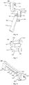
- FIG. 17 is a schematic perspective view of a cabling rack 190 of the front panel assembly shown in FIG. 4 .
- the cabling rack 190 includes a main body part 195 and an extending part 196.
- a first hole 191 for access of a cable and a second hole 192 for access of the light source 150 are formed in the main body part 195.
- a third hole 193 is formed in the extending part 196.
- an inner wall of the main body part 195 further extends leftwards to form a hook 194.
- the main body part 195 is disposed opposite to the side opening 421 of the second side cover plate.
- the hook 194 is clamped to the notch 770 to position the cabling rack 190 and the supporting frame 700.
- the third hole 193 is opposite to the fourth fixing hole 764 of the supporting frame 700.
- the cabling rack 190 and the supporting frame 700 are fixed via the third hole 193 and the fourth fixing hole 764 of the supporting frame 700.
- FIG. 18 is a schematic perspective view of the lower trim strip 800 of the front panel assembly shown in FIG. 4 .
- the lower trim strip 800 includes a lower trim strip body 801, and a first groove 802 opened forwards, a second groove 803 opened forwards and downwards and a third groove 805 opened backwards defined in the lower trim strip body 801.
- a first horizontal part 810, a vertical part 820, a second horizontal part 830, an inclined part 840, a first side part 851 and a second side part 852 are formed on a front surface of the lower trim strip body 801.
- the first horizontal part 810 constitutes a top face of the lower trim strip 800.
- the vertical part 820 is between the first horizontal part 810 and the second horizontal part 830, and the three jointly define the first groove 802.
- the protruding part 760 of the inclined plate 730 is wrapped within the first groove 802 of the lower trim strip 800.
- a fixing hole is formed in the position, corresponding to the fifth fixing hole of the supporting frame 700, of the vertical part 820, and a screw sequentially penetrates through the fixing hole and the fifth fixing hole of the supporting frame 700 to fix the supporting frame 700 and the lower trim strip 800.
- the lower trim strip 800 is designed as an integrally plastic part, and a screw penetrates through the vertical part 820 and the fifth fixing hole of the supporting frame 700 to fix the supporting frame 700 and the lower trim strip 800.
- the inclined part 840 is located below the second horizontal part in an inclined direction opposite to that of the first supporting part 701, and is provided with a first side part 851 and a second side part 852 at left and right sides thereof, respectively.
- the second horizontal part 830, the inclined part 840, the first side part 851 and the second side part 852 collectively define the second groove 803.
- a middle lower portion of the first supporting part 701, the second horizontal part 830, the inclined part 840, the first side part 851 and the second side part 852 jointly close the second opening, forming the handle part 804 opened downwards.
- the user can conveniently pull the front panel assembly 140 forwards and therefore pull the drawer 115 out by extending the hand into the handle part 804.
- fixing holes may be formed in bottom faces of the first side part 851 and the second side part 852.
- the third groove 805 is formed in a rear surface of the lower trim strip body 801, and the frame 501 of the rear end plate 500 can fit in the third groove 805.
- the present invention further provides an assembling method of a front panel assembly 140 of a drawer 115 of a refrigerator 100.
- FIG. 20 is a schematic process view of an assembling method of a front panel assembly 140 of a drawer 115 of a refrigerator 100 according to one embodiment of the present invention.
- the assembling method of the front panel assembly 140 of the embodiment of the present invention includes the steps:
- the light source 150 can be installed in the previous step or in the later step, making replacement of the light source 150 quite convenient.
- FIG. 21 is a schematic view of an assembling process of the front panel assembly 140 shown in FIG. 20 (a placing process of the light source 150 is not shown in the view).
- An assembling process of the front panel assembly 140 of the embodiment of the present invention includes the following steps:
- the light source 150 and the sealing plate 403 may also be installed after all other components are assembled, that is, the light source 150 and the sealing plate 403 are installed after the front end plate 200 and the upper cover plate 301 are installed. After the front panel assembly 140 is assembled, the front panel assembly 140 is fixed to the drawer body 120 to complete the installation of the drawer 115.
- FIG. 22 is a schematic structural view of a control part of a drawer 115 of a refrigerator 100 according to one embodiment of the present invention.
- FIG. 23 is a schematic control view of a detection unit 141 of a drawer 115 of a refrigerator 100 according to one embodiment of the present invention.
- the drawer 115 includes a drawer body 120, a front panel assembly 140, one or more detection units 141, a memory 142 and a lamplight controller 143.
- the detection unit 141 is configured to detect the state of a storage space and/or the state of an environment where the refrigerator 100 is located in order to obtain one or more state information.
- the memory 142 is configured to store lamplight control information, wherein the lamplight control information is associated with control content of the light source 150 according to each state information or the combination of multiple state information.
- the lamplight controller 143 is configured to control one or more light sources 150 according to the state information detected by the detection unit 141 and the lamplight control information stored in the memory 142.
- the drawer 115 of the embodiment of the present invention can control the action of the light source 150 according to different state information by the lamplight controller 143, so as to realize the change of lamplight.
- the lamplight control information includes color information and brightness information of lamplight realized by the action of the light source 150.
- the color of the lamplight can realize an RGB color mode outputting different parameters according to the magnitude of an applied voltage.
- the RGB color mode is a color based on spectrums corresponding to various permutations and combinations of red, green and blue light in a ratio between 0 and 255.
- the brightness of the lamplight may be achieved according to the magnitude of an applied current.
- the detection unit 141 of the embodiment of the present invention includes a temperature sensor 1411 disposed inside the storage space for detecting the temperature of the storage space.
- the state information includes a plurality of temperature information of the storage space. Color information of the lamplight realized by the light source 150 is correspondingly preset in the lamplight control information for each of the temperature information. Different temperatures in the drawer 115 may correspond to different colors, for example, low temperature corresponds to blue, and high temperature corresponds to red.
- the lamplight control information correspondingly presets the color information of the lamplight to change from a warm color system to a cold color system based on a plurality of temperature information from high to low temperature, and the color of the lamplight changes gradually, i.e., the temperature in the drawer 115 changes gradually.
- the detection unit 141 of the embodiment of the present invention includes a smell sensor 1412 disposed inside the storage space for detecting gas compositions of the storage space.
- the state information includes a plurality of gas information of the storage space.
- the color information of the lamplight realized by the light source 150 is correspondingly preset in the lamplight control information for the gas information.
- the color of the lamplight can be adjusted according to changes of values of the smell sensor 1412 to indicate the spoilage condition of food. For example, when food in the drawer 115 is normal, the color will show green, and when the food in the drawer 115 is rotting, the color will show red.
- the smell sensor 1412 is configured to detect gas compositions emitted by the food in a freshness period, a second freshness period and a past freshness period in the storage process in the storage space.
- the state information includes the gas information of the freshness period, the gas information of the second freshness period and the gas information of the past freshness period.
- the lamplight control information presets the color information of the lamplight for the gas information of the freshness period, the gas information of the second freshness period and the gas information of the past freshness period.
- the detection unit 141 of the embodiment of the present invention includes a light sensor 1413 disposed outside the refrigerator 100 for detecting the brightness of the environment where the refrigerator 100 is located.
- the state information includes a plurality of brightness information of the environment where the refrigerator 100 is located.
- Color information and brightness information of the lamplight realized by the light source 150 are preset in the lamplight control information for each brightness information.
- the light source 150 may adjust the brightness of lamplight display based on the ambient brightness sensed by the light sensor 1413. When the ambient brightness is high, the brightness of the lamplight is high correspondingly. When the ambient brightness is low, the brightness of the lamplight is low correspondingly. When the ambient brightness is extremely low, such as a night environment, the lamplight is displayed at an extremely low brightness, and the color of the lamplight may be set to yellow-white light for use as a small night lamp.
- the detection unit 141 of the embodiment of the present invention includes a sound pickup sensor 1414 disposed outside the refrigerator 100 for detecting a sound of an environment where the refrigerator 100 is located.
- the state information includes sound information of the environment where the refrigerator 100 is located.
- Color information and brightness information of the lamplight realized by the light source 150 are correspondingly preset in the lamplight control information for each sound information.
- the lamplight is rhythmically changed according to the tone.
- the detection unit 141 of the embodiment of the present invention includes a door opening and closing detection sensor 1415 for detecting an opening and closing condition of the drawer 115.
- the state information includes opening and closing information of the drawer 115.
- Color information and brightness information of the lamplight realized by the light source 150 are correspondingly preset in the lamplight control information for the opening and closing information.
- each detection unit 141 may be provided with a respective light source 150, and multiple detection units 141 may share one or more light sources 150.
- the drawer 115 of the embodiment of the present invention further includes: a lamplight function selection unit 144 and a detection unit controller 145.
- the lamplight function selection unit 144 is disposed on a main control display panel or a mobile terminal 147 of the refrigerator 100 for selecting predetermined functions realized by light changes, wherein each function is associated with one or more detection units 141.
- the detection unit controller 145 is configured to control one or more detection units 141 associated therewith based on a function selected by the lamplight function selection unit 144. Based on the light function selection unit 144, the user can control the different detection units 141 to be turned on or off as desired.
- the lamplight function selection unit 144 is disposed on the mobile terminal 147.
- the drawer 115 further includes a wireless communication unit disposed in the front panel assembly 140 for wirelessly communicating with the mobile terminal 147 to receive the function selected by the lamplight function selection unit 144.
Landscapes
- Engineering & Computer Science (AREA)
- Physics & Mathematics (AREA)
- General Engineering & Computer Science (AREA)
- Chemical & Material Sciences (AREA)
- Combustion & Propulsion (AREA)
- Mechanical Engineering (AREA)
- Thermal Sciences (AREA)
- General Physics & Mathematics (AREA)
- Optics & Photonics (AREA)
- Planar Illumination Modules (AREA)
- Devices That Are Associated With Refrigeration Equipment (AREA)
Abstract
Description
- The present invention relates to the technical field of freezing and refrigerating devices, in particular to a front panel assembly of a drawer of a refrigerator, a drawer of a refrigerator and a refrigerator.
- The refrigerator can keep food fresh and prolong the storage time of the food, and is a necessary household appliance. More and more refrigerators adopt a drawer type design. At present, the structural improvement of the drawer of the refrigerator is mainly improvement on drawer accessories, drawer interior lighting devices and the like, for example: a roller rail is disposed at the bottom of the drawer of the refrigerator, so that the drawer can be pulled and pushed conveniently; and a lighting lamp and the like are disposed at the inner wall of the side plate of the drawer body.
- One objective of the present invention is to provide a light emitting structure of a front panel assembly of a drawer of a refrigerator.
- One further objective of the present invention is to enable the front panel assembly of the drawer to achieve a visual sense of layering and a stereoscopic effect.
- Another further objective of the present invention is to simplify an installation and replacement process of a light source of the front panel assembly of the drawer.
- Particularly, the present invention provides a front panel assembly of a drawer of a refrigerator, comprising:
- a front panel body, defining an accommodating cavity; and
- a light emitting mechanism, disposed in the accommodating cavity, and including a light source, a light guide body and a reflector, wherein the light guide body is disposed below the light source and is provided with an inclined plane; the reflector is disposed obliquely below the inclined plane; wherein
- a front end face of the front panel body is provided with a light transmitting plate, and light emitted by the light source is transmitted by the light guide body to reach the inclined plane to be emitted out from the light transmitting plate after being reflected by the reflector.
- Optionally, the light transmitting plate is vertically disposed. A horizontal distance between the inclined plane from a bottom edge thereof to a top edge thereof and the light transmitting plate is gradually increased, and light vertically reaches the inclined plane downwards, and then is emitted out from the light transmitting plate after being horizontally reflected forwards by the reflector.
- Optionally, the inclined plane and the light transmitting plate form an acute angle in degrees of 20°-45°.
- Optionally, the front end face of the front panel body is provided with a light-proof plate and the light transmitting plate disposed up and down. The light guide body includes a first light guide part and a second light guide part disposed up and down. The first light guide part is disposed corresponding to the light-proof plate, and the light source is arranged thereon. The second light guide part is disposed corresponding to the light transmitting plate and is provided with a vertical surface and the inclined plane. The vertical surface is attached to the light transmitting plate, and the inclined plane and the vertical surface form an acute angle.
- Optionally, the front panel assembly further includes a supporting frame disposed in the accommodating cavity, fixed to the front panel body, configured to support the light guide body and comprising a first supporting part provided with an inclined structure matched with the inclined plane. The reflector is a reflecting film, and is attached to a lower surface of the inclined plane and/or an upper surface of the first supporting part.
- Optionally, the front panel assembly further includes a lower trim strip provided with grooves opened forwards and downwards, and fixed to the supporting frame and the front panel body. The lower trim strip and at least one part of a lower surface of the first supporting part jointly close an opening located in a bottom of the front panel body, and a handle part with a downward opening is formed between the lower trim strip and the first supporting part, so that the front panel assembly is pulled conveniently forwards by the handle part.
- Optionally, an inclination angle of the first supporting part is 20°-45°.
- Optionally, the supporting frame further includes a second supporting part disposed above the first supporting part and configured to form an accommodating space in between together with the light guide body. A side opening corresponding to the accommodating space is formed on a side face of the front panel body, and the light source is placed in or taken out of the accommodating space through the side opening.
- Optionally, the front panel assembly further includes a light uniformizing plate disposed in the accommodating space. The light source is a lamp strip or a lamp panel, and light emitted by the light source vertically enters the light guide body downwards to reach the inclined plane after passing through the light uniformizing plate.
- Optionally, the front panel assembly further includes a heat dissipation piece disposed in the accommodating space and configured to dissipate heat from the light source and the light uniformizing plate; wherein a light source placing area is defined among the heat dissipation piece, the light uniformizing plate and the light guide body, and the light source is disposed in the light source placing area so as to limit the light source in a front-back direction.
- Optionally, the front panel assembly further includes a cabling rack disposed corresponding to the side opening and provided with a main body part and an extending part. A first hole for access of a cable and a second hole for access of the light source are formed in the main body part, and the extending part and the second supporting part are fixed.
- The present invention further provides a drawer of a refrigerator, including:
- a drawer body, defining a storage space therein; and
- the foregoing front panel assembly disposed in front of the drawer body.
- The present invention further provides a refrigerator provided with the forgoing drawer of the refrigerator.
- According to the front panel assembly of the drawer of the refrigerator and the drawer of the refrigerator of the present invention, the accommodating cavity is defined in the front panel body, the light source, the light guide body and the reflector are disposed in the accommodating cavity, and the light transmitting plate is disposed on the front end face of the front panel body, so that light emitted by the light source is transmitted by the light guide body to reach the inclined plane and then to be emitted out from the light transmitting plate after being reflected by the reflector, and light emission of the front panel assembly of the drawer of the refrigerator is realized. Meanwhile, the front panel assembly of the drawer of the refrigerator of the present invention is disposed such that the light source is transmitted in the light guide body and then is emitted out after being reflected by the reflector, and the light emitting effect of the front panel assembly can be adjusted by adjusting each component of the light emitting mechanism.
- Further, the light transmitting plate of the front panel assembly of the drawer of the refrigerator of the present invention is vertically disposed. The horizontal distance between the inclined plane from the bottom edge thereof to the top edge thereof and the light transmitting plate is gradually increased. The light vertically reaches the inclined plane downwards and then is emitted out from the light transmitting plate after being horizontally reflected forwards by the reflector. The front panel assembly of the drawer realizes a visual sense of layering and a stereoscopic effect by changing the longitudinal direction of a structural piece from the shallower to the deeper.
- Further, the front panel assembly of the drawer of the refrigerator of the present invention utilizes the supporting frame provided with the inclined structure matched with the inclined plane of the light guide body to fix the light guide body, so as to ensure position stability of the light guide body, and utilizes the reflecting film for reflection, so as to realize low cost and easy assembling. Moreover, the reflecting effect of the reflecting film can be made more stable by the supporting frame.
- Further, the accommodating space is formed between the supporting frame and the light guide body of the front panel assembly of the drawer of the refrigerator of the present invention, so that the light source is convenient to place in and take out, and the light source can be easily and conveniently installed and replaced.
- According to the following detailed descriptions of specific embodiments of the present invention in conjunction with the drawings, those skilled in the art will more clearly understand the above and other objectives, advantages and features of the present invention.
- Some specific embodiments of the present invention are described in detail below with reference to the drawings by way of example and not limitation. The same reference numerals in the drawings indicate the same or similar components or parts. Those skilled in the art should understand that these drawings are not necessarily drawn in scale. In figures:
-
FIG. 1 is a schematic front view of a refrigerator according to one embodiment of the present invention. -
FIG. 2 is a schematic perspective view of a refrigerator body and a first drawer of the refrigerator shown inFIG. 1 . -
FIG. 3 is a schematic perspective view of a drawer of the refrigerator shown inFIG. 1 . -
FIG. 4 is a schematic perspective view of a front panel assembly of the drawer of the refrigerator shown inFIG. 3 . -
FIG. 5 is a schematic exploded view of the front panel assembly shown inFIG. 4 . -
FIG. 6 is a schematic bottom view of the front panel assembly shown inFIG. 4 . -
FIG. 7 is a schematic cross-sectional view of the front panel assembly shown inFIG. 6 . -
FIG. 8 is a schematic partial enlarged view of the front panel assembly shown inFIG. 7 . -
FIG. 9 is a schematic perspective view of some assemblies of the front panel assembly shown inFIG. 4 . -
FIG. 10 is another schematic perspective view of some assemblies of the front panel assembly shown inFIG. 4 . -
FIG. 11 is a schematic partial enlarged view of some assemblies of the front panel assembly shown inFIG. 10 . -
FIG. 12 is a schematic perspective view of an upper cover plate of the front panel assembly shown inFIG. 4 . -
FIG. 13 is a schematic perspective view of an upper cover bracket of the front panel assembly shown inFIG. 4 . -
FIG. 14 is another schematic perspective view of the upper cover bracket of the front panel assembly shown inFIG. 13 . -
FIG. 15 is a schematic perspective view of a heat dissipation piece, a light uniformizing plate and a light guide body of the front panel assembly shown inFIG. 4 . -
FIG. 16 is a schematic perspective view of a supporting frame of the front panel assembly shown inFIG. 4 . -
FIG. 17 is a schematic perspective view of a cabling rack of the front panel assembly shown inFIG. 4 . -
FIG. 18 is a schematic perspective view of a lower trim strip of the front panel assembly shown inFIG. 4 . -
FIG. 19 is a schematic effect view of the drawer of the refrigerator shown inFIG. 4 . -
FIG. 20 is a schematic process view of an assembling method of a front panel assembly of a drawer of a refrigerator according to one embodiment of the present invention. -
FIG. 21 is a schematic view of an assembling process of the front panel assembly shown inFIG. 20 . -
FIG. 22 is a schematic structural view of a control part of a drawer of a refrigerator according to one embodiment of the present invention. -
FIG. 23 is a schematic control view of a detection unit of a drawer of a refrigerator according to one embodiment of the present invention. -
FIG. 1 is a schematic front view of arefrigerator 100 according to one embodiment of the present invention.FIG. 2 is a schematic perspective view of arefrigerator body 110 and afirst drawer 115 of therefrigerator 100 shown inFIG. 1 .FIG. 3 is a schematic perspective view of adrawer 115 of therefrigerator 100 shown inFIG. 1 .FIG. 4 is a schematic perspective view of afront panel assembly 140 shown inFIG. 3 .FIG. 5 is a schematic exploded view of thefront panel assembly 140 shown inFIG. 4 . Therefrigerator 100 of the embodiment of the present invention may generally include: arefrigerator body 110, afirst door body 111, asecond door body 112, athird door body 113, afourth door body 114, afirst drawer 115 and asecond drawer 116. A plurality of storage compartments are defined within therefrigerator body 110. Thefirst door body 111, thesecond door body 112, thethird door body 113 and thefourth door body 114 are all rotary door bodies, and are pivotally disposed on the front side of one storage compartment through hinges respectively. Generally, the storage compartment corresponding to thefirst door body 111 and thesecond door body 112 is a refrigerating compartment, the storage compartment corresponding to thethird door body 113 is a temperature changing compartment or a freezing compartment, and the storage compartment corresponding to thefourth door body 114 is a freezing compartment. Thefirst drawer 115 and thesecond drawer 116 are disposed between thefirst door body 111 and thethird door body 113, and between thesecond door body 112 and thefourth door body 114, respectively, as a refrigerating compartment or a temperature changing compartment. - The
drawer 115 of therefrigerator 100 of the embodiment of the present invention includes adrawer body 120 and afront panel assembly 140. A storage space is defined within thedrawer body 120. Thedrawer body 120 can be pulled to slide in therefrigerator body 110 through guide rails 130. Thefront panel assembly 140 is disposed in front of thedrawer body 120. - In some embodiments, the
front panel assembly 140 includes: a front panel body and a light emitting mechanism. The front panel body defines an accommodating cavity. The light emitting mechanism is disposed in the accommodating cavity and includes alight source 150, alight guide body 600 and areflector 180. Thelight guide body 600 is disposed below thelight source 150 and is provided with aninclined plane 602. Thereflector 180 is disposed obliquely below theinclined plane 602. A front end face of the front panel body is provided with alight transmitting plate 202. Light emitted by thelight source 150 is transmitted by thelight guide body 600 to reach theinclined plane 602 and then to be emitted out from thelight transmitting plate 202 after being reflected by thereflector 180. According to thefront panel assembly 140 and thedrawer 115 of the embodiment of the present invention, the accommodating cavity is defined in the front panel body, thelight source 150, thelight guide body 600 and thereflector 180 are disposed in the accommodating cavity, and thelight transmitting plate 202 is disposed on the front end face of the front panel body, so that light emitted by thelight source 150 is transmitted by thelight guide body 600 to reach theinclined plane 602 and then to be emitted out from thelight transmitting plate 202 after being reflected by thereflector 180, and light emission of thefront panel assembly 140 is realized. Meanwhile, thefront panel assembly 140 of the embodiment of the present invention is disposed such that thelight source 150 is transmitted in thelight guide body 600 and then is emitted out after being reflected by thereflector 180, and the light emitting effect of thefront panel assembly 140 can be adjusted by adjusting each component of the light emitting mechanism. - In some embodiments, the
light transmitting plate 202 is vertically disposed. The horizontal distance between theinclined plane 602 from a bottom edge thereof to a top edge thereof and thelight transmitting plate 202 is gradually increased. The light vertically reaches theinclined plane 602 downwards and then is emitted out from thelight transmitting plate 202 after being horizontally reflected forwards by thereflector 180. Thelight transmitting plate 202 of thefront panel assembly 140 of the embodiment of the present invention is vertically disposed. The horizontal distance between theinclined plane 602 from the bottom edge thereof to the top edge thereof and thelight transmitting plate 202 is gradually increased (has an increasing tendency). The light vertically reaches theinclined plane 602 downwards and then is emitted out from thelight transmitting plate 202 after being horizontally reflected forwards by thereflector 180. A longitudinal depth difference is produced by means of the structure of theinclined plane 602. Meanwhile, theinclined plane 602 can have the appearances of brushed leather lines, text, icons, etc., bringing a visual sense of layering.FIG. 19 is a schematic effect view of thefront panel assembly 140 shown inFIG. 4 . In one preferred embodiment, theinclined plane 602 and thelight transmitting plate 202 form an acute angle θ in degrees of 20°-45°, for example, 20°, 25°, 35° and 42°. - In some embodiments, the front end face of the front panel body of the embodiment of the present invention is provided with a light-
proof plate 201 and thelight transmitting plate 202 disposed up and down. Thelight guide body 600 includes a firstlight guide part 631 and a secondlight guide part 632 disposed up and down, wherein the firstlight guide part 631 is disposed corresponding to the light-proof plate 201, and thelight source 150 is arranged thereon. The secondlight guide part 632 is disposed corresponding to thelight transmitting plate 202 and is provided with a vertical plane and the inclined plane. The vertical plane is attached to thelight transmitting plate 202, and the inclined plane and the vertical plane form an acute angle, wherein the inclined plane of the secondlight guide part 632 constitutes theinclined plane 602 of thelight guide body 600, and the light vertically reaches the inclined plane of the secondlight guide part 632 downwards and penetrates through the vertical plane of the secondlight guide part 632 and thelight transmitting plate 202 to be emitted out after being horizontally reflected forwards by thereflector 180. The front end face of thefront panel assembly 140 of the embodiment of the present invention is provided with the light-proof plate 201 and thelight transmitting plate 202. Correspondingly, thelight guide body 600 includes the firstlight guide part 631 and the secondlight guide part 632, making the boundary between a light transmitting part and a light-proof part obvious and improving the sense of layering, meanwhile ensuring that the whole area of the light transmitting part is luminous and there will be no situation where a local portion is completely grey and affects perception of users. In addition, the firstlight guide part 631 may also be configured to fix thelight guide body 600. - In some embodiments, the
front panel assembly 140 of the embodiment of the present invention further includes: a supportingframe 700, disposed in the accommodating cavity, fixed to the front panel body, and configured to support thelight guide body 600. The supportingframe 700 includes a first supportingpart 701 provided with an inclined structure, and the inclined structure of the first supportingpart 701 is matched with theinclined plane 602. Thereflector 180 is a reflecting film, located between theinclined plane 602 and the first supportingpart 701 and attached to theinclined plane 602, or attached to the first supportingpart 701, or is formed by carrying out surface treatment on an upper surface of the first supportingpart 701. Thefront panel assembly 140 of the embodiment of the present invention utilizes the supportingframe 700 provided with the inclined structure matched with theinclined plane 602 of thelight guide body 600 to fix thelight guide body 600, so as to ensure position stability of thelight guide body 600, and utilizes the reflectingfilm 180 for reflection, so as to realize low cost and easy assembling. Moreover, the reflecting effect of the reflectingfilm 180 can be made more stable by the supportingframe 700. - In some embodiments, the supporting
frame 700 of the embodiment of the present invention further includes a second supporting part 702 disposed above the first supportingpart 701 and configured to form an accommodating space in between together with the firstlight guide part 631. Aside opening 421 corresponding to the accommodating space is formed on a side face of the front panel body, and thelight source 150 is placed in or taken out of the accommodating space through theside opening 421. The accommodating space is formed between the supportingframe 700 and thelight guide body 600 of thefront panel assembly 140 of the embodiment of the present invention, so that thelight source 150 is convenient to place in and take out, and thelight source 150 can be easily and conveniently installed and replaced. - In some embodiments, the
front panel assembly 140 of the embodiment of the present invention further includes alight uniformizing plate 160 disposed on thelight guide body 600. Thelight source 150 is a lamp strip or a lamp panel, and light emitted by thelight source 150 vertically enters thelight guide body 600 downwards to reach theinclined plane 602 after passing through thelight uniformizing plate 160. - In some embodiments, the
front panel assembly 140 of the embodiment of the present invention further includes aheat dissipation piece 170 disposed in the accommodating space and configured to dissipate heat from thelight source 150 and thelight uniformizing plate 160, and a lightsource placing area 151 is defined among theheat dissipation piece 170, thelight uniformizing plate 160 and thelight guide body 600. Thelight source 150 is disposed in the lightsource placing area 151 so that thelight source 150 is limited in a front-back direction. Thefront panel assembly 140 of thedrawer 115 of the embodiment of the present invention is further provided with theheat dissipation piece 170 in the accommodating space to dissipate heat from thelight source 150 and thelight uniformizing plate 160, the situation that the service life of thelight source 150 is affected due to the fact that thefront panel assembly 140 is overheated is avoided, and meanwhile potential safety hazards can be avoided. In addition, the lightsource placing area 151 is defined by theheat dissipation piece 170, thelight uniformizing plate 160 and thelight guide body 600 together to limit the position of thelight source 150 in the front-back direction. - In some embodiments, the
front panel assembly 140 of embodiment of the present invention further includes acabling rack 190 disposed corresponding to theside opening 421, and provided with amain body part 195 and an extendingpart 196. Afirst hole 191 for access of a cable and asecond hole 192 for access of thelight source 150 are formed in themain body part 195. The extendingpart 196 and the second supporting part 702 are fixed. In one embodiment, in order to ensure fixing stability of thecabling rack 190, ahook 194 is further formed on thecabling rack 190, the supportingframe 700 is provided with anotch 770, and thehook 194 fits in thenotch 770. - In some embodiments, the
front panel assembly 140 of the embodiment of the present invention further includes alower trim strip 800 fixed to the supportingframe 700 and the front panel body. Thelower trim strip 800 and at least one part of a lower surface of the first supportingpart 701 jointly form a bottom of thefront panel assembly 140. In one preferred embodiment, thelower trim strip 800 is provided with agroove 803 opened forwards and downwards. In this way, ahandle part 804 with a downward opening is formed between thelower trim strip 800 and the first supportingpart 701, so that thefront panel assembly 140 is pulled conveniently forwards by thehandle part 804. In one more preferred embodiment, an inclination angle of the first supportingpart 701 is 20°-45°. Thefront panel assembly 140 of the embodiment of the present invention closes the opening through thelower trim strip 800 and the supportingframe 700, and meanwhile thehandle part 804 is formed in between. This structure is quite ingenious and facilitates a user to pull thedrawer 115. Meanwhile, the inclination angle of the first supportingpart 701 takes into account both the light reflection and the hand feeling. An inclination included angle α between the first supporting part and the vertical plane is set to 20°-45°, for example, 20°, 25°, 35° and 42°. - The
front panel assembly 140 of the embodiment of the present invention includes the front panel body, atouchpad 302, aheat insulator 520, the light emitting mechanism, the supportingframe 700, thelight uniformizing plate 160, theheat dissipation piece 170, thecabling rack 190 and thelower trim strip 800.FIG. 5 is a schematic exploded view of thefront panel assembly 140 shown inFIG. 4 .FIG. 6 is a schematic bottom view of thefront panel assembly 140 shown inFIG. 4 .FIG. 7 is a schematic cross-sectional view of thefront panel assembly 140 shown inFIG. 6 .FIG. 8 is a schematic partial enlarged view of thefront panel assembly 140 shown inFIG. 7 .FIG. 9 is a schematic perspective view of some assemblies of thefront panel assembly 140 shown inFIG. 4 .FIG. 10 is another schematic perspective view of some assemblies of thefront panel assembly 140 shown inFIG. 4 .FIG. 11 is a schematic partial enlarged view of some assemblies of thefront panel assembly 140 shown inFIG. 10 . - The front panel body includes a
front end plate 200, arear end plate 500, a fixingframe 900, a firstside cover plate 401, a secondside cover plate 402 and anupper cover mechanism 300. The firstside cover plate 401 and the secondside cover plate 402 are oppositely disposed, thefront end plate 200 and therear end plate 500 are disposed on a front side and a rear side respectively, and a first opening (not shown) and a second opening (not shown) are formed in a top and a bottom respectively. Theupper cover mechanism 300 closes the first opening, and the supportingframe 700 and thelower trim strip 800 close the second opening. - The
front end plate 200 is vertically disposed and includes the light-proof plate 201 and thelight transmitting plate 202 located below the light-proof plate 201, and a light transmitting area is formed on thelight transmitting plate 202. Thefront end plate 200 may be of an integrated structure, and may also be a split structure. - The
rear end plate 500 includes aframe 501 and aprotruding part 502 protruded backwards from the periphery of theframe 501. A groove (not shown) is formed in a back face of theframe 501. A plurality of assemblingholes 503 are formed in theprotruding part 502 for fixing thefront panel assembly 140 to the guide rails 130. - The fixing
frame 900 includes aframe body 901 and aframe protrusion 902 extending forwards from theframe body 901. Theframe protrusion 902 is matched with the groove of therear end plate 500. The fixingframe 900 is configured to seal the connection between therear end plate 500 and other components of the front panel body, and asealing strip 510 is further disposed between the groove of therear end plate 500 and theframe protrusion 902 to enhance sealing. Further, in order to enhance the heat insulating performance of thefront panel assembly 140, theheat insulator 520, such as two heat insulating blocks, is disposed in theprotruding part 502. - The first
side cover plate 401 and the secondside cover plate 402 each include a sidecover plate body 410 and a side coverplate extending part 420. The sidecover plate bodies 410 of the firstside cover plate 401 and the secondside cover plate 402 are disposed relatively in parallel. Each side coverplate extending part 420 is formed by extending from the sidecover plate body 410 on one side toward the sidecover plate body 410 on the opposite side. Afirst fixing hole 431 and asecond fixing hole 432 are respectively formed in the side coverplate extending part 420. The firstside cover plate 401 and the secondside cover plate 402 are fixed to theupper cover mechanism 300 through thefirst fixing hole 431, and the firstside cover plate 401 and the secondside cover plate 402 are fixed to the supportingframe 700 through thesecond fixing hole 432. Theside opening 421 is formed in the sidecover plate body 410 of the secondside cover plate 402 for placement-in of thelight source 150 and introduction of the cable. A sealingplate 403 is further disposed on the sidecover plate body 410 of the secondside cover plate 402, and configured to seal theside opening 421 after thelight source 150 and the cable are placed therein. - The
upper cover mechanism 300 includes anupper cover plate 301 and anupper cover bracket 303.FIG. 12 is a schematic perspective view of theupper cover plate 301.FIG. 13 is a schematic perspective view of theupper cover bracket 303.FIG. 14 is another schematic perspective view of theupper cover bracket 303. - The
upper cover plate 301 is provided with an uppercover plate body 311 and an upper coverplate extending part 312. The uppercover plate body 311 fully or partially forms a touch area on an outer surface thereof, and arib 313 is formed in a downward extending manner at a position, corresponding to the touch area, of the inner surface thereof. Therib 313 defines agroove 314. Meanwhile, a plurality of sixth fixing hooks 326 are formed at intervals on the inner wall of therib 313, and thetouchpad 302 is fixed in thegroove 314 via the plurality of sixth fixing hooks 326. - The
upper cover bracket 303 is provided with a brackettop plate 333, a bracketfront wall plate 334, a bracketside wall plate 335, and abracket extending part 337. Arecess 331 is formed in the position, corresponding to thegroove 314 of theupper cover plate 301, on the brackettop plate 333. Therecess 331 wraps thegroove 314 of theupper cover plate 301 and thetouchpad 302. A top face of the brackettop plate 333 is of an inclined structure, and forms an acute angle together with the horizontal plane, and the top face gradually seal the first opening upwards from thefront end plate 200 to therear end plate 500. The uppercover plate body 311 is matched with the top face of the brackettop plate 333 and is also obliquely disposed. Acabling hole 332 is also formed in therecess 331 in a penetrating manner for introducing the cable to supply power, signals and the like to thetouchpad 302. A fixinghole 336 is formed in the bracketfront wall plate 334. The firstside cover plate 401, the secondside cover plate 402 and theupper cover bracket 303 are fixed through thefirst fixing hole 431 in the side coverplate extending part 420 and the fixinghole 336 in theupper cover bracket 303. The bracketside wall plate 335 is configured to limit the distance between thefront end plate 200 and therear end plate 500. The brackettop plate 333 extends backwards to form thebracket extending part 337, and thebracket extending part 337 is disposed to be beneficial to fixing between theupper cover bracket 303 and therear end plate 500. - The
upper cover plate 301 and theupper cover bracket 303 are fixed by disposing a plurality of clamping structures. An intersection of the uppercover plate body 311 and the upper coverplate extending part 312 extends downwards at intervals in a length direction to form a plurality of first fixing hooks 321. Correspondingly, first fixingholes 341 are formed in the positions, corresponding to the first fixing hooks 321 respectively, at the intersection of the brackettop plate 333 and thebracket extending part 337. The uppercover plate body 311 extends downwards at intervals in a length direction at a position, close to an outer wall of thefront end plate 200, of therib 313 to form two second fixing hooks 322. Correspondingly, second fixingholes 342 are formed in positions, corresponding to the second fixing hooks 322 respectively, of therecess 331 of the brackettop plate 333. The other side, away from the upper coverplate extending part 312, of the uppercover plate body 311 extends downwards at intervals in the length direction to form athird fixing hook 323, afourth fixing hook 324 and afifth fixing hook 325, wherein thethird fixing hook 323 and thefourth fixing hook 324 are arranged on a left side and a right side of therib 313 respectively and are close to a left edge and a right edge of the uppercover plate body 311 respectively. Thefifth fixing hook 325 is located between therib 313 and thefourth fixing hook 324. Correspondingly, athird fixing hole 343, afourth fixing hole 344 and afifth fixing hole 345 are formed in positions, corresponding to thethird fixing hook 323, thefourth fixing hook 324 and thefifth fixing hook 325, of the brackettop plate 333. The foregoing several clamping structures are mainly configured to ensure fixing of theupper cover plate 301 and theupper cover bracket 303 in the vertical direction. In addition, a limitingprotrusion 327 is also formed on an inner surface of the uppercover plate body 311 in a width direction, and the limitingprotrusion 327 can be a wedge-shaped protrusion. Correspondingly, the brackettop plate 333 forms a limitinggroove 346 at a position corresponding to the limitingprotrusion 327, and a limitingprotrusion 347 for cooperating with the limitingprotrusion 327 is disposed in the limitinggroove 346. During installation, the several fixing hooks are controlled to be inserted into the corresponding fixing holes respectively and then slide to match and fix the two limiting protrusions. Understandably, two or more of the above clamping structures may be disposed to fix theupper cover plate 301 and theupper cover bracket 303. - The light emitting mechanism includes the
light source 150, thelight guide body 600 and the reflectingfilm 180. The supportingframe 700 includes the first supportingpart 701, the second supporting part 702 and a third supportingpart 703. The specific structure of thelight guide body 600 and the supportingframe 700 and their cooperation will be described below in turn.FIG. 15 is a schematic perspective view of theheat dissipation piece 170, thelight uniformizing plate 160 and thelight guide body 600.FIG. 16 is a schematic perspective view of the supportingframe 700. - The
light guide body 600 is disposed below thelight source 150 and is provided with thehorizontal plane 601, theinclined plane 602 and thevertical plane 603. Light emitted by thelight source 150 is emitted downwards from thehorizontal plane 601 of thelight guide body 600 to reach theinclined plane 602 of thelight guide body 600, then is reflected forwards to reach thevertical plane 603 of thelight guide body 600, and then is emitted from the light transmitting area. Specifically, thelight guide body 600 includes the firstlight guide part 631 and the secondlight guide part 632, and the two light guide parts may be of an integrated structure or split structures, preferably the integrated structure. The material of thelight guide body 600 may be transparent acryl. The firstlight guide part 631 is L-shaped in longitudinal section and is provided with a first connectingpart 610 and a second connectingpart 620. The first connectingpart 610 is horizontally disposed, and an upper surface thereof forms thehorizontal plane 601 of thelight guide body 600 and is configured to place thelight source 150, thelight uniformizing plate 160 and theheat dissipation piece 170. A fixing hole (not shown) for fixing to the supportingframe 700 is formed in a rear side face of the first connecting part, and agroove 611 with a downward opening for matching with the supportingframe 700 is formed in a lower surface of the first connecting part. The second connectingpart 620 is vertically disposed against the light-proof plate 201, and a fixinghole 621 for fixing to the firstside cover plate 401 and the secondside cover plate 402 is formed in a front-back direction thereof in a penetrating manner. The secondlight guide part 632 is a right triangle in longitudinal section, and is provided with a horizontal plane, a vertical plane, and an inclined plane. In one embodiment, an upper portion of the horizontal plane of the secondlight guide part 632 is provided with the first connectingpart 610. The vertical plane of the secondlight guide part 632 corresponds to the light transmitting area. The inclined plane of the secondlight guide part 632 is theinclined plane 602 of thelight guide body 600, and is matched with the first supportingpart 701, and the reflectingfilm 180 is disposed between the two. When thefront end plate 200 is of an integrated structure, the light-proof plate 201 is also used as a pasting area. Specifically, when thefront end plate 200 is assembled, the light-proof plate 201 is pasted to the side coverplate extending part 420 and the second connectingpart 620 so as to fix thefront end plate 200. - The supporting
frame 700 is made from aluminum alloy and is an integrally-formed workpiece which is provided with the first supportingpart 701, the second supporting part 702 and the third supportingpart 703, mainly including a firstvertical plate 711, a firsthorizontal plate 721, a secondvertical plate 712, a secondhorizontal plate 722 and aninclined plate 730 disposed in turn. - The first
vertical plate 711 forms the third supportingpart 703, and is provided with afirst fixing hole 761 and asecond fixing hole 762. The side coverplate extending part 420 and the third supportingpart 703 are fixed via thesecond fixing hole 432 of the side coverplate extending part 420 and thefirst fixing hole 761 of the supportingframe 700. The second connectingpart 620 and the third supportingpart 703 are fixed through the fixinghole 621 of the second connectingpart 620 and thesecond fixing hole 762 of the supportingframe 700. The firstvertical plate 711 extends horizontally backwards at a central portion thereof to form a thirdhorizontal plate 723 having anotch 770 on the thirdhorizontal plate 723 for positioning of thecabling rack 190 and the supportingframe 700. - The first
vertical plate 711 extends backwards at a bottom end thereof to form the firsthorizontal plate 721, and the other end of the firsthorizontal plate 721 extends downwards to form the secondvertical plate 712. The secondvertical plate 712 extends forwards at a bottom end thereof to form the secondhorizontal plate 722. The firsthorizontal plate 721, the secondvertical plate 712, and the secondhorizontal plate 722 constitute the second supporting part 702 provided with anaccommodating groove 750. A middle lower portion of the second connectingpart 620, the first connectingpart 610, a middle upper portion of the secondvertical plate 712, and the firsthorizontal plate 721 collectively define an accommodating space for placing thelight source 150, thelight uniformizing plate 160 and theheat dissipation piece 170. Athird fixing hole 763 is formed in the secondvertical plate 712 in a penetrating manner, and the first connectingpart 610 and the second supporting part 702 are fixed through thethird fixing hole 763 of the supporting frame and the fixing hole of the first connectingpart 610. A front end of the secondhorizontal plate 722 further extends upwards to form avertical protrusion 740 for matching with thegroove 611 of the first connectingpart 610. In addition, afourth fixing hole 764 is also formed in the secondvertical plate 712 in a penetrating manner for fixing of thecabling rack 190 and the supportingframe 700. - The
inclined plate 730 is formed in the manner that the other end of the secondhorizontal plate 722 obliquely extends forwards and downwards to constitute the first supportingpart 701. A back face of theinclined plate 730 is further provided with aprotruding part 760. A fifth fixing hole (not shown) is formed in theprotruding part 760 for fixing of thelower trim strip 800 and the supportingframe 700. - The
light source 150 is a lamp strip or lamp panel. Thelight uniformizing plate 160 is disposed on the first connectingpart 610, and light emitted from thelight source 150 vertically enters thelight guide body 600 downwards after passing through thelight uniformizing plate 160 and finally reaches theinclined plane 602. - The
heat dissipation piece 170 is provided with a firsthorizontal part 171, a firstvertical part 172 extending vertically upwards from a rear end of the firsthorizontal part 171, a secondhorizontal part 173 extending horizontally backwards from the other end of the firstvertical part 172, and a secondvertical part 174 extending vertically downwards from the other end of the secondhorizontal part 173 and terminating beyond the firsthorizontal part 171. Theheat dissipation piece 170 cooperates with thelight uniformizing plate 160 and the first connectingpart 610 to define the lightsource placing area 151 of thelight source 150. The size of theheat dissipation piece 170, thelight uniformizing plate 160 and the second supporting part 702 is such that the width of the lightsource placing area 151 is the minimum assembling gap of thelamp strip 150, so that the two ends of thelamp strip 150 can be limited. -
FIG. 17 is a schematic perspective view of acabling rack 190 of the front panel assembly shown inFIG. 4 . Thecabling rack 190 includes amain body part 195 and an extendingpart 196. Afirst hole 191 for access of a cable and asecond hole 192 for access of thelight source 150 are formed in themain body part 195. Athird hole 193 is formed in the extendingpart 196. In addition, an inner wall of themain body part 195 further extends leftwards to form ahook 194. Themain body part 195 is disposed opposite to theside opening 421 of the second side cover plate. Thehook 194 is clamped to thenotch 770 to position thecabling rack 190 and the supportingframe 700. Thethird hole 193 is opposite to thefourth fixing hole 764 of the supportingframe 700. Thecabling rack 190 and the supportingframe 700 are fixed via thethird hole 193 and thefourth fixing hole 764 of the supportingframe 700. -
FIG. 18 is a schematic perspective view of thelower trim strip 800 of the front panel assembly shown inFIG. 4 . Thelower trim strip 800 includes a lowertrim strip body 801, and afirst groove 802 opened forwards, asecond groove 803 opened forwards and downwards and athird groove 805 opened backwards defined in the lowertrim strip body 801. Specifically, a firsthorizontal part 810, avertical part 820, a secondhorizontal part 830, aninclined part 840, afirst side part 851 and asecond side part 852 are formed on a front surface of the lowertrim strip body 801. - The first
horizontal part 810 constitutes a top face of thelower trim strip 800. Thevertical part 820 is between the firsthorizontal part 810 and the secondhorizontal part 830, and the three jointly define thefirst groove 802. The protrudingpart 760 of theinclined plate 730 is wrapped within thefirst groove 802 of thelower trim strip 800. It may be that a fixing hole is formed in the position, corresponding to the fifth fixing hole of the supportingframe 700, of thevertical part 820, and a screw sequentially penetrates through the fixing hole and the fifth fixing hole of the supportingframe 700 to fix the supportingframe 700 and thelower trim strip 800. It also may be that thelower trim strip 800 is designed as an integrally plastic part, and a screw penetrates through thevertical part 820 and the fifth fixing hole of the supportingframe 700 to fix the supportingframe 700 and thelower trim strip 800. - The
inclined part 840 is located below the second horizontal part in an inclined direction opposite to that of the first supportingpart 701, and is provided with afirst side part 851 and asecond side part 852 at left and right sides thereof, respectively. The secondhorizontal part 830, theinclined part 840, thefirst side part 851 and thesecond side part 852 collectively define thesecond groove 803. A middle lower portion of the first supportingpart 701, the secondhorizontal part 830, theinclined part 840, thefirst side part 851 and thesecond side part 852 jointly close the second opening, forming thehandle part 804 opened downwards. The user can conveniently pull thefront panel assembly 140 forwards and therefore pull thedrawer 115 out by extending the hand into thehandle part 804. In addition, fixing holes may be formed in bottom faces of thefirst side part 851 and thesecond side part 852. - The
third groove 805 is formed in a rear surface of the lowertrim strip body 801, and theframe 501 of therear end plate 500 can fit in thethird groove 805. - The present invention further provides an assembling method of a
front panel assembly 140 of adrawer 115 of arefrigerator 100.FIG. 20 is a schematic process view of an assembling method of afront panel assembly 140 of adrawer 115 of arefrigerator 100 according to one embodiment of the present invention. The assembling method of thefront panel assembly 140 of the embodiment of the present invention includes the steps: - S102: assembling a
light guide body 600, areflector 180 and a supportingframe 700 to obtain a first assembly, wherein thereflector 180 is located between thelight guide body 600 and the supportingframe 700; - S104: respectively installing a first
side cover plate 401 and a secondside cover plate 402 at a left end and a right end of the assembled first assembly to obtain a second assembly; and - S106: respectively installing a
front end plate 200 and arear end plate 500 on a front side and a rear side of the assembled second assembly, and installing anupper cover mechanism 300 on a top of the assembled second assembly to obtain thefront panel assembly 140 of thedrawer 115 of therefrigerator 100; - When the
front panel assembly 140 of the embodiment of the present invention is assembled, thelight source 150 can be installed in the previous step or in the later step, making replacement of thelight source 150 quite convenient. -
FIG. 21 is a schematic view of an assembling process of thefront panel assembly 140 shown inFIG. 20 (a placing process of thelight source 150 is not shown in the view). An assembling process of thefront panel assembly 140 of the embodiment of the present invention includes the following steps: - 1) The
reflector 180, thelight guide body 600 and the supportingframe 700 are assembled. A reflectingfilm 180 is attached to aninclined plane 602 of thelight guide body 600, or surface treatment is carried out on aninclined plate 730 of the supportingframe 700 to form the reflectingfilm 180, or the reflectingfilm 180 is attached to an upper surface of theinclined plate 730 of the supportingframe 700. Theinclined plane 602 of thelight guide body 600 abuts against theinclined plate 730 of the supportingframe 700. A second connectingpart 620 abuts against a firstvertical plate 711. Fixingholes 621 of the second connectingpart 620 are in one-to-one correspondence with second fixingholes 762 of the supporting frame, and these holes are fixed with screws. Agroove 611 of a first connectingpart 610 is matched with avertical protrusion 740 of a secondhorizontal plate 722, fixing holes of the first connectingpart 610 are in one-to-one correspondence with third fixingholes 763 of the supportingframe 700, and these holes are fixed with screws. In this way, a middle lower portion of the second connectingpart 620, the first connectingpart 610, a middle upper portion of a secondvertical plate 712 and a firsthorizontal plate 721 jointly define an accommodating space. - 2) A
light uniformizing plate 160 and aheat dissipation piece 170 are installed. Thelight uniformizing plate 160 and theheat dissipation piece 170 are placed in the accommodating space. A bottom face of thelight uniformizing plate 160 is attached to an upper surface of the first connectingpart 610, and a front side face is attached to a rear side face of the second connectingpart 620. A firsthorizontal part 171 of theheat dissipation piece 170 is attached to an upper surface of thelight uniformizing plate 160, and a secondvertical part 174 is attached to a front side face of the secondvertical plate 712. In this way, theheat dissipation piece 170 is cooperated with thelight uniformizing plate 160 and the first connectingpart 610 to define a lightsource placing area 151. - 3) A
lower trim strip 800 and the supportingframe 700 are cooperatively fixed. Afirst groove 802 of thelower trim strip 800 wraps aprotruding part 760 of the supportingframe 700. Avertical part 820 of thelower trim strip 800 and a fifth fixing hole of the supportingframe 700 are fixed by using screws, and screws are screwed upwards at fixing holes in bottom faces of afirst side part 851 and asecond side part 852. - 4) A
cabling rack 190 is installed. Ahook 194 of thecabling rack 190 is clamped at anotch 770 of the supportingframe 700, and then thecabling rack 190 and the secondvertical plate 712 are fixed via athird hole 193 of thecabling rack 190 and afourth fixing hole 764 of the supporting frame by using screws, so that afirst hole 191 and asecond hole 192 of thecabling rack 190 are disposed in a left-right direction. - 5) A first
side cover plate 401 and a secondside cover plate 402 are installed. The firstside cover plate 401 is installed on a left side, and the secondside cover plate 402 is installed on a right side. Aside opening 421 of the second side cover plate is aligned with thefirst hole 191 and thesecond hole 192 of thecabling rack 190. Side coverplate extending parts 420 of the firstside cover plate 401 and the secondside cover plate 402 shield a middle upper portion of the firstvertical plate 711 of the supportingframe 700, respectively. The side coverplate extending parts 420 and the firstvertical plate 711 of the supportingframe 700 are fixed via second fixing holes 432 of the side cover plate extending parts and afirst fixing hole 761 of the supporting frame. - 6) A
rear end plate 500 and a fixingframe 900 are installed. Aframe 501 of therear end plate 500 is fitted into athird groove 805 of thelower trim strip 800. A sealingstrip 510 is added into a groove of theframe 501, and then the fixingframe 900 is installed, so that aframe protrusion 902 is fitted into the groove of theframe 501. - 7) An
upper cover bracket 303 is mounted. Theupper cover bracket 303 is placed in an opening at the top formed among the firstside cover plate 401, therear end plate 500 and the secondside cover plate 402, and theupper cover bracket 303 is fixed to the firstside cover plate 401 and the secondside cover plate 402 respectively via first fixingholes 431 of the side cover plate extending parts and a fixinghole 336 of the upper cover bracket. Abracket extending part 337 is matched with a top face of therear end plate 500. - 8) A
front end plate 200 is installed. Thefront end plate 200 is glued to the side coverplate extending parts 420 and the second connectingpart 620 by coating an inner side face of a light-proof plate 201 with glue, and alight transmitting plate 202 corresponds to a vertical plane of a secondlight guide part 632. - 9) A
light source 150 is installed. Thelight source 150 is placed into the lightsource placing area 151 through theside opening 421 of the second side cover plate and thesecond hole 192 of thecabling rack 190. - 10) A sealing
plate 403 is installed. The sealingplate 403 is installed at theside opening 421 of the second side cover plate, and assembling of thefront panel assembly 140 is completed. - 11) An
upper cover plate 301 is installed. Atouchpad 302 is fixed in agroove 314 of theupper cover plate 301 via asixth fixing hook 326 of theupper cover plate 301. Then, afirst fixing hook 321, asecond fixing hook 322, athird fixing hook 323, afourth fixing hook 324, and afifth fixing hook 325 of theupper cover plate 301 are fitted into afirst fixing hole 341, asecond fixing hole 342, athird fixing hole 343, afourth fixing hole 344, and afifth fixing hole 345 of theupper cover bracket 303, respectively. A limitingprotrusion 327 of the upper cover plate is fitted to a limitingprotrusion 347 of the upper cover bracket, and therefore theupper cover plate 301 is fixed to theupper cover bracket 303. Thetouchpad 302 is located in arecess 331 of theupper cover bracket 303. - It should be understood that the
light source 150 and the sealingplate 403 may also be installed after all other components are assembled, that is, thelight source 150 and the sealingplate 403 are installed after thefront end plate 200 and theupper cover plate 301 are installed. After thefront panel assembly 140 is assembled, thefront panel assembly 140 is fixed to thedrawer body 120 to complete the installation of thedrawer 115. - The present invention further provides a lamplight-
controllable drawer 115 with thefront panel assembly 140 as described above.FIG. 22 is a schematic structural view of a control part of adrawer 115 of arefrigerator 100 according to one embodiment of the present invention.FIG. 23 is a schematic control view of adetection unit 141 of adrawer 115 of arefrigerator 100 according to one embodiment of the present invention. - The
drawer 115 includes adrawer body 120, afront panel assembly 140, one ormore detection units 141, amemory 142 and alamplight controller 143. Thedetection unit 141 is configured to detect the state of a storage space and/or the state of an environment where therefrigerator 100 is located in order to obtain one or more state information. Thememory 142 is configured to store lamplight control information, wherein the lamplight control information is associated with control content of thelight source 150 according to each state information or the combination of multiple state information. Thelamplight controller 143 is configured to control one or morelight sources 150 according to the state information detected by thedetection unit 141 and the lamplight control information stored in thememory 142. Thedrawer 115 of the embodiment of the present invention can control the action of thelight source 150 according to different state information by thelamplight controller 143, so as to realize the change of lamplight. - The lamplight control information includes color information and brightness information of lamplight realized by the action of the
light source 150. The color of the lamplight can realize an RGB color mode outputting different parameters according to the magnitude of an applied voltage. The RGB color mode is a color based on spectrums corresponding to various permutations and combinations of red, green and blue light in a ratio between 0 and 255. The brightness of the lamplight may be achieved according to the magnitude of an applied current. - In some embodiments, the
detection unit 141 of the embodiment of the present invention includes atemperature sensor 1411 disposed inside the storage space for detecting the temperature of the storage space. The state information includes a plurality of temperature information of the storage space. Color information of the lamplight realized by thelight source 150 is correspondingly preset in the lamplight control information for each of the temperature information. Different temperatures in thedrawer 115 may correspond to different colors, for example, low temperature corresponds to blue, and high temperature corresponds to red. In one implementation, the lamplight control information correspondingly presets the color information of the lamplight to change from a warm color system to a cold color system based on a plurality of temperature information from high to low temperature, and the color of the lamplight changes gradually, i.e., the temperature in thedrawer 115 changes gradually. - In some embodiments, the
detection unit 141 of the embodiment of the present invention includes asmell sensor 1412 disposed inside the storage space for detecting gas compositions of the storage space. The state information includes a plurality of gas information of the storage space. The color information of the lamplight realized by thelight source 150 is correspondingly preset in the lamplight control information for the gas information. The color of the lamplight can be adjusted according to changes of values of thesmell sensor 1412 to indicate the spoilage condition of food. For example, when food in thedrawer 115 is normal, the color will show green, and when the food in thedrawer 115 is rotting, the color will show red. In one implementation, thesmell sensor 1412 is configured to detect gas compositions emitted by the food in a freshness period, a second freshness period and a past freshness period in the storage process in the storage space. The state information includes the gas information of the freshness period, the gas information of the second freshness period and the gas information of the past freshness period. The lamplight control information presets the color information of the lamplight for the gas information of the freshness period, the gas information of the second freshness period and the gas information of the past freshness period. - In some embodiments, the
detection unit 141 of the embodiment of the present invention includes alight sensor 1413 disposed outside therefrigerator 100 for detecting the brightness of the environment where therefrigerator 100 is located. The state information includes a plurality of brightness information of the environment where therefrigerator 100 is located. Color information and brightness information of the lamplight realized by thelight source 150 are preset in the lamplight control information for each brightness information. Thelight source 150 may adjust the brightness of lamplight display based on the ambient brightness sensed by thelight sensor 1413. When the ambient brightness is high, the brightness of the lamplight is high correspondingly. When the ambient brightness is low, the brightness of the lamplight is low correspondingly. When the ambient brightness is extremely low, such as a night environment, the lamplight is displayed at an extremely low brightness, and the color of the lamplight may be set to yellow-white light for use as a small night lamp. - In some embodiments, the
detection unit 141 of the embodiment of the present invention includes asound pickup sensor 1414 disposed outside therefrigerator 100 for detecting a sound of an environment where therefrigerator 100 is located. The state information includes sound information of the environment where therefrigerator 100 is located. Color information and brightness information of the lamplight realized by thelight source 150 are correspondingly preset in the lamplight control information for each sound information. When the sound of the surroundings of therefrigerator 100 changes, for example, music is played, and the like, the lamplight is rhythmically changed according to the tone. - In some embodiments, the
detection unit 141 of the embodiment of the present invention includes a door opening andclosing detection sensor 1415 for detecting an opening and closing condition of thedrawer 115. The state information includes opening and closing information of thedrawer 115. Color information and brightness information of the lamplight realized by thelight source 150 are correspondingly preset in the lamplight control information for the opening and closing information. When thedrawer 115 fails, for example, when a door body of thedrawer 115 is not closed tightly, the lamplight can make a red lamplight flashing at a certain frequency to remind the user. - Understandably, one or more of the foregoing
detection units 141 may be disposed for thesame drawer 115. Eachdetection unit 141 may be provided with a respectivelight source 150, andmultiple detection units 141 may share one or morelight sources 150. - The
drawer 115 of the embodiment of the present invention further includes: a lamplightfunction selection unit 144 and adetection unit controller 145. The lamplightfunction selection unit 144 is disposed on a main control display panel or amobile terminal 147 of therefrigerator 100 for selecting predetermined functions realized by light changes, wherein each function is associated with one ormore detection units 141. Thedetection unit controller 145 is configured to control one ormore detection units 141 associated therewith based on a function selected by the lamplightfunction selection unit 144. Based on the lightfunction selection unit 144, the user can control thedifferent detection units 141 to be turned on or off as desired. In some embodiments, the lamplightfunction selection unit 144 is disposed on themobile terminal 147. Thedrawer 115 further includes a wireless communication unit disposed in thefront panel assembly 140 for wirelessly communicating with themobile terminal 147 to receive the function selected by the lamplightfunction selection unit 144. - Hereto, those skilled in the art should realize that although multiple exemplary embodiments of the present invention have been shown and described in detail herein, without departing from the spirit and scope of the present invention, many other variations or modifications that conform to the principles of the present invention can still be directly determined or deduced from the contents disclosed in the present invention. Therefore, the scope of the present invention should be understood and recognized as covering all these other variations or modifications.
Claims (13)
- A front panel assembly of a drawer of a refrigerator, comprising:a front panel body, defining an accommodating cavity; anda light emitting mechanism, disposed in the accommodating cavity, and comprising a light source, a light guide body and a reflector, wherein the light guide body is disposed below the light source and is provided with an inclined plane; the reflector is disposed obliquely below the inclined plane; whereina front end face of the front panel body is provided with a light transmitting plate, and light emitted by the light source is transmitted by the light guide body to reach the inclined plane, and then to be emitted out from the light transmitting plate after being reflected by the refl ector.
- The front panel assembly of the drawer of the refrigerator according to claim 1, whereinthe light transmitting plate is vertically disposed; anda horizontal distance between the inclined plane from a bottom edge thereof to a top edge thereof and the light transmitting plate is gradually increased, and the light vertically reaches the inclined plane downwards, and then is emitted out from the light transmitting plate after being horizontally reflected forwards by the reflector.
- The front panel assembly of the drawer of the refrigerator according to claim 2, wherein the inclined plane and the light transmitting plate form an acute angle in degrees of 20°-45°.
- The front panel assembly of the drawer of the refrigerator according to claim 2, wherein the front end face of the front panel body is provided with a light-proof plate and the light transmitting plate disposed up and down; andthe light guide body comprises a first light guide part and a second light guide part disposed up and down; whereinthe first light guide part is disposed corresponding to the light-proof plate, and the light source is arranged thereon; andthe second light guide part is disposed corresponding to the light transmitting plate and is provided with a vertical plane and the inclined plane, the vertical plane is attached to the light transmitting plate, and the inclined plane and the vertical plane form an acute angle.
- The front panel assembly of the drawer of the refrigerator according to claim 2, further comprising:a supporting frame, disposed in the accommodating cavity, fixed to the front panel body, configured to support the light guide body and comprising a first supporting part provided with an inclined structure matched with the inclined plane; andthe reflector is a reflecting film, and is attached to a lower surface of the inclined plane and/or an upper surface of the first supporting part.
- The front panel assembly of the drawer of the refrigerator according to claim 5, further comprising
a lower trim strip, provided with grooves opened forwards and downwards and fixed to the supporting frame and the front panel body, wherein the lower trim strip and at least one part of a lower surface of the first supporting part jointly close an opening located in a bottom of the front panel body, and a handle part with a downward opening is formed between the lower trim strip and the first supporting part, so that the front panel assembly is pulled conveniently forwards by the handle part. - The front panel assembly of the drawer of the refrigerator according to claim 6, wherein an inclination angle of the first supporting part is 20°-45°.
- The front panel assembly of the drawer of the refrigerator according to claim 5, wherein
the supporting frame further comprises a second supporting part, disposed above the first supporting part and configured to form an accommodating space in between together with the light guide body; and
a side opening corresponding to the accommodating space is formed on a side face of the front panel body, and the light source is placed in or taken out of the accommodating space through the side opening. - The front panel assembly of the drawer of the refrigerator according to claim 8, further comprising:a light uniformizing plate, disposed in the accommodating space;wherein the light source is a lamp strip or a lamp panel, and the light emitted by the light source vertically enters the light guide body downwards to reach the inclined plane after passing through the light uniformizing plate.
- The front panel assembly of the drawer of the refrigerator according to claim 9, further comprising:
a heat dissipation piece, disposed in the accommodating space and configured to dissipate heat from the light source and the light uniformizing plate; wherein a light source placing area is defined among the heat dissipation piece, the light uniformizing plate and the light guide body, and the light source is disposed in the light source placing area so as to be limited in a front-back direction. - The front panel assembly of the drawer of the refrigerator according to claim 10, further comprising:
a cabling rack, disposed corresponding to the side opening and provided with a main body part and an extending part, wherein a first hole for access of a cable and a second hole for access of the light source are formed in the main body part, and the extending part and the second supporting part are fixed. - A drawer of a refrigerator, comprising:a drawer body, defining a storage space therein; andthe front panel assembly according to any one of claims 1-11, disposed in front of the drawer body.
- A refrigerator, provided with the drawer of the refrigerator according to claim 12.
Applications Claiming Priority (2)
| Application Number | Priority Date | Filing Date | Title |
|---|---|---|---|
| CN201910177244.XA CN111076489B (en) | 2019-03-08 | 2019-03-08 | Refrigerator drawer front panel assembly, drawer and refrigerator |
| PCT/CN2019/103288 WO2020181736A1 (en) | 2019-03-08 | 2019-08-29 | Front panel assembly of drawer of refrigerator, drawer of refrigerator, and refrigerator |
Publications (3)
| Publication Number | Publication Date |
|---|---|
| EP3916327A1 true EP3916327A1 (en) | 2021-12-01 |
| EP3916327A4 EP3916327A4 (en) | 2022-04-20 |
| EP3916327B1 EP3916327B1 (en) | 2023-02-22 |
Family
ID=70310196
Family Applications (1)
| Application Number | Title | Priority Date | Filing Date |
|---|---|---|---|
| EP19919346.7A Active EP3916327B1 (en) | 2019-03-08 | 2019-08-29 | Refrigerator comprises a drawer |
Country Status (4)
| Country | Link |
|---|---|
| US (1) | US11280544B2 (en) |
| EP (1) | EP3916327B1 (en) |
| CN (1) | CN111076489B (en) |
| WO (1) | WO2020181736A1 (en) |
Families Citing this family (2)
| Publication number | Priority date | Publication date | Assignee | Title |
|---|---|---|---|---|
| JP7726932B2 (en) * | 2023-01-24 | 2025-08-20 | 日立グローバルライフソリューションズ株式会社 | refrigerator |
| WO2025036250A1 (en) * | 2023-08-11 | 2025-02-20 | 青岛海尔电冰箱有限公司 | Fresh-keeping device for refrigerator, and refrigerator |
Family Cites Families (29)
| Publication number | Priority date | Publication date | Assignee | Title |
|---|---|---|---|---|
| KR20060007615A (en) * | 2004-07-20 | 2006-01-26 | 아이에이치엘 주식회사 | Refrigerator Lighting |
| ITMI20040455U1 (en) * | 2004-10-08 | 2005-01-08 | Thermo Glass Door S P A | BRIGHT DOOR FOR EXHIBITORS IN PARTICULAR FOR REFRIGERATORS PROVIDED WITH THIS DOOR |
| US7147341B2 (en) | 2004-10-12 | 2006-12-12 | Illinois Tool Works Inc | Light assembly |
| JP4786992B2 (en) * | 2005-10-07 | 2011-10-05 | クリナップ株式会社 | Built-in equipment for kitchen furniture and kitchen furniture having the same |
| JP2007238049A (en) * | 2006-03-13 | 2007-09-20 | Kojima Press Co Ltd | Illumination device for vehicle interior parts and overhead console with illumination device |
| CN101424768A (en) * | 2007-11-02 | 2009-05-06 | 北京京东方光电科技有限公司 | Light guide board, back light source and LCD |
| JP5197185B2 (en) * | 2008-06-30 | 2013-05-15 | 三菱電機株式会社 | refrigerator |
| DE102010003355A1 (en) * | 2010-03-26 | 2011-09-29 | BSH Bosch und Siemens Hausgeräte GmbH | dishwasher |
| JP5246240B2 (en) * | 2010-10-15 | 2013-07-24 | 三菱電機株式会社 | Cooker |
| CN202074348U (en) * | 2011-05-16 | 2011-12-14 | 深圳市华星光电技术有限公司 | Liquid-crystal display and backlight module |
| JP6030388B2 (en) * | 2012-09-12 | 2016-11-24 | シャープ株式会社 | refrigerator |
| JP6012567B2 (en) * | 2013-09-10 | 2016-10-25 | 日立アプライアンス株式会社 | refrigerator |
| KR102147940B1 (en) * | 2013-12-27 | 2020-08-25 | 엘지이노텍 주식회사 | Lighting device |
| WO2016169900A1 (en) * | 2015-04-21 | 2016-10-27 | BSH Hausgeräte GmbH | Home appliance device |
| CN105698476B (en) | 2016-03-09 | 2018-10-12 | 青岛海尔股份有限公司 | fridge drawer |
| CN105972926A (en) * | 2016-05-30 | 2016-09-28 | 合肥华凌股份有限公司 | Lamp box assembly and electrical equipment therein |
| CN206094732U (en) | 2016-09-19 | 2017-04-12 | Tcl家用电器(合肥)有限公司 | Refrigerator drawer and refrigerator |
| CN106369490A (en) * | 2016-10-17 | 2017-02-01 | 青岛海尔股份有限公司 | Refrigerator and illuminating part thereof |
| CN106766652A (en) * | 2016-11-23 | 2017-05-31 | 青岛海尔股份有限公司 | Display device and the refrigerator drawer with it |
| US10466411B2 (en) * | 2017-04-19 | 2019-11-05 | Omachron Intellectual Property Inc. | LED light source |
| JP2018206149A (en) * | 2017-06-06 | 2018-12-27 | オムロン株式会社 | Input apparatus |
| JP6388691B1 (en) * | 2017-07-11 | 2018-09-12 | 三菱電機エンジニアリング株式会社 | Storage and electronic refrigerator |
| KR102334259B1 (en) * | 2017-07-14 | 2021-12-03 | 엘지전자 주식회사 | Refrigerator |
| DE102018203272A1 (en) * | 2018-03-06 | 2019-09-12 | BSH Hausgeräte GmbH | Domestic refrigerating appliance with a drawer and method for producing the household refrigerating appliance |
| DE102018003587B4 (en) * | 2018-05-03 | 2020-12-31 | Emz-Hanauer Gmbh & Co. Kgaa | Household refrigerator with a wall lamp |
| KR102663561B1 (en) * | 2018-12-28 | 2024-05-08 | 엘지전자 주식회사 | Refrigerator |
| CN111664623B (en) * | 2019-03-05 | 2023-04-07 | Bsh家用电器有限公司 | Domestic refrigeration device with a drawer |
| US10983379B2 (en) * | 2019-04-29 | 2021-04-20 | Hisense Visual Technology Co., Ltd. | Display device |
| US11035531B1 (en) * | 2019-10-15 | 2021-06-15 | Sub-Zero Group, Inc. | Shelf light assembly |
-
2019
- 2019-03-08 CN CN201910177244.XA patent/CN111076489B/en active Active
- 2019-08-29 WO PCT/CN2019/103288 patent/WO2020181736A1/en not_active Ceased
- 2019-08-29 US US17/436,968 patent/US11280544B2/en active Active
- 2019-08-29 EP EP19919346.7A patent/EP3916327B1/en active Active
Also Published As
| Publication number | Publication date |
|---|---|
| US20220042738A1 (en) | 2022-02-10 |
| CN111076489A (en) | 2020-04-28 |
| EP3916327B1 (en) | 2023-02-22 |
| CN111076489B (en) | 2020-10-30 |
| US11280544B2 (en) | 2022-03-22 |
| EP3916327A4 (en) | 2022-04-20 |
| WO2020181736A1 (en) | 2020-09-17 |
Similar Documents
| Publication | Publication Date | Title |
|---|---|---|
| US10704826B2 (en) | Refrigerator | |
| US11168937B2 (en) | Refrigerator | |
| US10378815B2 (en) | Refrigerator | |
| US20240068735A1 (en) | Refrigerator | |
| US8523374B2 (en) | Refrigerator and door thereof | |
| US12117237B2 (en) | Refrigerator | |
| KR20220146241A (en) | Refrigerator | |
| US11280544B2 (en) | Front panel assembly of drawer of refrigerator, drawer of refrigerator, and refrigerator | |
| CN111664646B (en) | Front panel assembly of drawer of refrigerator, drawer and refrigerator | |
| KR20220030124A (en) | Refrigerator | |
| KR20180056870A (en) | Refrigerator | |
| CN111664647B (en) | Refrigerator drawer front panel assembly and refrigerator drawer assembly method | |
| KR20230117498A (en) | Home appliance | |
| CN111664648B (en) | Refrigerator drawer and refrigerator having the same | |
| US12331987B2 (en) | Flush-mount light assembly for a refrigerator appliance | |
| CN211372907U (en) | Refrigerator with decorative lamp | |
| CN221324806U (en) | refrigerator | |
| KR20230071624A (en) | Home appliance | |
| CN217979421U (en) | refrigerator | |
| KR20240002901A (en) | Refrigerator | |
| CN118517838A (en) | refrigerator |
Legal Events
| Date | Code | Title | Description |
|---|---|---|---|
| STAA | Information on the status of an ep patent application or granted ep patent |
Free format text: STATUS: THE INTERNATIONAL PUBLICATION HAS BEEN MADE |
|
| PUAI | Public reference made under article 153(3) epc to a published international application that has entered the european phase |
Free format text: ORIGINAL CODE: 0009012 |
|
| STAA | Information on the status of an ep patent application or granted ep patent |
Free format text: STATUS: REQUEST FOR EXAMINATION WAS MADE |
|
| 17P | Request for examination filed |
Effective date: 20210823 |
|
| AK | Designated contracting states |
Kind code of ref document: A1 Designated state(s): AL AT BE BG CH CY CZ DE DK EE ES FI FR GB GR HR HU IE IS IT LI LT LU LV MC MK MT NL NO PL PT RO RS SE SI SK SM TR |
|
| STAA | Information on the status of an ep patent application or granted ep patent |
Free format text: STATUS: EXAMINATION IS IN PROGRESS |
|
| A4 | Supplementary search report drawn up and despatched |
Effective date: 20220321 |
|
| RIC1 | Information provided on ipc code assigned before grant |
Ipc: F25D 27/00 20060101ALI20220315BHEP Ipc: F25D 25/02 20060101AFI20220315BHEP |
|
| 17Q | First examination report despatched |
Effective date: 20220404 |
|
| DAV | Request for validation of the european patent (deleted) | ||
| DAX | Request for extension of the european patent (deleted) | ||
| GRAP | Despatch of communication of intention to grant a patent |
Free format text: ORIGINAL CODE: EPIDOSNIGR1 |
|
| STAA | Information on the status of an ep patent application or granted ep patent |
Free format text: STATUS: GRANT OF PATENT IS INTENDED |
|
| INTG | Intention to grant announced |
Effective date: 20221005 |
|
| GRAS | Grant fee paid |
Free format text: ORIGINAL CODE: EPIDOSNIGR3 |
|
| GRAA | (expected) grant |
Free format text: ORIGINAL CODE: 0009210 |
|
| STAA | Information on the status of an ep patent application or granted ep patent |
Free format text: STATUS: THE PATENT HAS BEEN GRANTED |
|
| AK | Designated contracting states |
Kind code of ref document: B1 Designated state(s): AL AT BE BG CH CY CZ DE DK EE ES FI FR GB GR HR HU IE IS IT LI LT LU LV MC MK MT NL NO PL PT RO RS SE SI SK SM TR |
|
| REG | Reference to a national code |
Ref country code: GB Ref legal event code: FG4D |
|
| REG | Reference to a national code |
Ref country code: CH Ref legal event code: EP |
|
| REG | Reference to a national code |
Ref country code: AT Ref legal event code: REF Ref document number: 1549748 Country of ref document: AT Kind code of ref document: T Effective date: 20230315 Ref country code: IE Ref legal event code: FG4D |
|
| REG | Reference to a national code |
Ref country code: DE Ref legal event code: R096 Ref document number: 602019025691 Country of ref document: DE |
|
| REG | Reference to a national code |
Ref country code: LT Ref legal event code: MG9D |
|
| REG | Reference to a national code |
Ref country code: NL Ref legal event code: MP Effective date: 20230222 |
|
| REG | Reference to a national code |
Ref country code: AT Ref legal event code: MK05 Ref document number: 1549748 Country of ref document: AT Kind code of ref document: T Effective date: 20230222 |
|
| PG25 | Lapsed in a contracting state [announced via postgrant information from national office to epo] |
Ref country code: RS Free format text: LAPSE BECAUSE OF FAILURE TO SUBMIT A TRANSLATION OF THE DESCRIPTION OR TO PAY THE FEE WITHIN THE PRESCRIBED TIME-LIMIT Effective date: 20230222 Ref country code: PT Free format text: LAPSE BECAUSE OF FAILURE TO SUBMIT A TRANSLATION OF THE DESCRIPTION OR TO PAY THE FEE WITHIN THE PRESCRIBED TIME-LIMIT Effective date: 20230622 Ref country code: NO Free format text: LAPSE BECAUSE OF FAILURE TO SUBMIT A TRANSLATION OF THE DESCRIPTION OR TO PAY THE FEE WITHIN THE PRESCRIBED TIME-LIMIT Effective date: 20230522 Ref country code: NL Free format text: LAPSE BECAUSE OF FAILURE TO SUBMIT A TRANSLATION OF THE DESCRIPTION OR TO PAY THE FEE WITHIN THE PRESCRIBED TIME-LIMIT Effective date: 20230222 Ref country code: LV Free format text: LAPSE BECAUSE OF FAILURE TO SUBMIT A TRANSLATION OF THE DESCRIPTION OR TO PAY THE FEE WITHIN THE PRESCRIBED TIME-LIMIT Effective date: 20230222 Ref country code: LT Free format text: LAPSE BECAUSE OF FAILURE TO SUBMIT A TRANSLATION OF THE DESCRIPTION OR TO PAY THE FEE WITHIN THE PRESCRIBED TIME-LIMIT Effective date: 20230222 Ref country code: HR Free format text: LAPSE BECAUSE OF FAILURE TO SUBMIT A TRANSLATION OF THE DESCRIPTION OR TO PAY THE FEE WITHIN THE PRESCRIBED TIME-LIMIT Effective date: 20230222 Ref country code: ES Free format text: LAPSE BECAUSE OF FAILURE TO SUBMIT A TRANSLATION OF THE DESCRIPTION OR TO PAY THE FEE WITHIN THE PRESCRIBED TIME-LIMIT Effective date: 20230222 Ref country code: AT Free format text: LAPSE BECAUSE OF FAILURE TO SUBMIT A TRANSLATION OF THE DESCRIPTION OR TO PAY THE FEE WITHIN THE PRESCRIBED TIME-LIMIT Effective date: 20230222 |
|
| PG25 | Lapsed in a contracting state [announced via postgrant information from national office to epo] |
Ref country code: SE Free format text: LAPSE BECAUSE OF FAILURE TO SUBMIT A TRANSLATION OF THE DESCRIPTION OR TO PAY THE FEE WITHIN THE PRESCRIBED TIME-LIMIT Effective date: 20230222 Ref country code: PL Free format text: LAPSE BECAUSE OF FAILURE TO SUBMIT A TRANSLATION OF THE DESCRIPTION OR TO PAY THE FEE WITHIN THE PRESCRIBED TIME-LIMIT Effective date: 20230222 Ref country code: IS Free format text: LAPSE BECAUSE OF FAILURE TO SUBMIT A TRANSLATION OF THE DESCRIPTION OR TO PAY THE FEE WITHIN THE PRESCRIBED TIME-LIMIT Effective date: 20230622 Ref country code: GR Free format text: LAPSE BECAUSE OF FAILURE TO SUBMIT A TRANSLATION OF THE DESCRIPTION OR TO PAY THE FEE WITHIN THE PRESCRIBED TIME-LIMIT Effective date: 20230523 Ref country code: FI Free format text: LAPSE BECAUSE OF FAILURE TO SUBMIT A TRANSLATION OF THE DESCRIPTION OR TO PAY THE FEE WITHIN THE PRESCRIBED TIME-LIMIT Effective date: 20230222 |
|
| PG25 | Lapsed in a contracting state [announced via postgrant information from national office to epo] |
Ref country code: SM Free format text: LAPSE BECAUSE OF FAILURE TO SUBMIT A TRANSLATION OF THE DESCRIPTION OR TO PAY THE FEE WITHIN THE PRESCRIBED TIME-LIMIT Effective date: 20230222 Ref country code: RO Free format text: LAPSE BECAUSE OF FAILURE TO SUBMIT A TRANSLATION OF THE DESCRIPTION OR TO PAY THE FEE WITHIN THE PRESCRIBED TIME-LIMIT Effective date: 20230222 Ref country code: EE Free format text: LAPSE BECAUSE OF FAILURE TO SUBMIT A TRANSLATION OF THE DESCRIPTION OR TO PAY THE FEE WITHIN THE PRESCRIBED TIME-LIMIT Effective date: 20230222 Ref country code: DK Free format text: LAPSE BECAUSE OF FAILURE TO SUBMIT A TRANSLATION OF THE DESCRIPTION OR TO PAY THE FEE WITHIN THE PRESCRIBED TIME-LIMIT Effective date: 20230222 Ref country code: CZ Free format text: LAPSE BECAUSE OF FAILURE TO SUBMIT A TRANSLATION OF THE DESCRIPTION OR TO PAY THE FEE WITHIN THE PRESCRIBED TIME-LIMIT Effective date: 20230222 |
|
| REG | Reference to a national code |
Ref country code: DE Ref legal event code: R097 Ref document number: 602019025691 Country of ref document: DE |
|
| PG25 | Lapsed in a contracting state [announced via postgrant information from national office to epo] |
Ref country code: SK Free format text: LAPSE BECAUSE OF FAILURE TO SUBMIT A TRANSLATION OF THE DESCRIPTION OR TO PAY THE FEE WITHIN THE PRESCRIBED TIME-LIMIT Effective date: 20230222 |
|
| PLBE | No opposition filed within time limit |
Free format text: ORIGINAL CODE: 0009261 |
|
| STAA | Information on the status of an ep patent application or granted ep patent |
Free format text: STATUS: NO OPPOSITION FILED WITHIN TIME LIMIT |
|
| 26N | No opposition filed |
Effective date: 20231123 |
|
| PG25 | Lapsed in a contracting state [announced via postgrant information from national office to epo] |
Ref country code: SI Free format text: LAPSE BECAUSE OF FAILURE TO SUBMIT A TRANSLATION OF THE DESCRIPTION OR TO PAY THE FEE WITHIN THE PRESCRIBED TIME-LIMIT Effective date: 20230222 |
|
| PG25 | Lapsed in a contracting state [announced via postgrant information from national office to epo] |
Ref country code: MC Free format text: LAPSE BECAUSE OF FAILURE TO SUBMIT A TRANSLATION OF THE DESCRIPTION OR TO PAY THE FEE WITHIN THE PRESCRIBED TIME-LIMIT Effective date: 20230222 |
|
| REG | Reference to a national code |
Ref country code: CH Ref legal event code: PL |
|
| PG25 | Lapsed in a contracting state [announced via postgrant information from national office to epo] |
Ref country code: MC Free format text: LAPSE BECAUSE OF FAILURE TO SUBMIT A TRANSLATION OF THE DESCRIPTION OR TO PAY THE FEE WITHIN THE PRESCRIBED TIME-LIMIT Effective date: 20230222 |
|
| PG25 | Lapsed in a contracting state [announced via postgrant information from national office to epo] |
Ref country code: LU Free format text: LAPSE BECAUSE OF NON-PAYMENT OF DUE FEES Effective date: 20230829 |
|
| PG25 | Lapsed in a contracting state [announced via postgrant information from national office to epo] |
Ref country code: LU Free format text: LAPSE BECAUSE OF NON-PAYMENT OF DUE FEES Effective date: 20230829 Ref country code: CH Free format text: LAPSE BECAUSE OF NON-PAYMENT OF DUE FEES Effective date: 20230831 |
|
| REG | Reference to a national code |
Ref country code: BE Ref legal event code: MM Effective date: 20230831 |
|
| REG | Reference to a national code |
Ref country code: IE Ref legal event code: MM4A |
|
| PG25 | Lapsed in a contracting state [announced via postgrant information from national office to epo] |
Ref country code: IT Free format text: LAPSE BECAUSE OF FAILURE TO SUBMIT A TRANSLATION OF THE DESCRIPTION OR TO PAY THE FEE WITHIN THE PRESCRIBED TIME-LIMIT Effective date: 20230222 |
|
| PG25 | Lapsed in a contracting state [announced via postgrant information from national office to epo] |
Ref country code: IE Free format text: LAPSE BECAUSE OF NON-PAYMENT OF DUE FEES Effective date: 20230829 |
|
| PG25 | Lapsed in a contracting state [announced via postgrant information from national office to epo] |
Ref country code: IE Free format text: LAPSE BECAUSE OF NON-PAYMENT OF DUE FEES Effective date: 20230829 |
|
| PG25 | Lapsed in a contracting state [announced via postgrant information from national office to epo] |
Ref country code: BE Free format text: LAPSE BECAUSE OF NON-PAYMENT OF DUE FEES Effective date: 20230831 |
|
| PG25 | Lapsed in a contracting state [announced via postgrant information from national office to epo] |
Ref country code: BG Free format text: LAPSE BECAUSE OF FAILURE TO SUBMIT A TRANSLATION OF THE DESCRIPTION OR TO PAY THE FEE WITHIN THE PRESCRIBED TIME-LIMIT Effective date: 20230222 |
|
| PG25 | Lapsed in a contracting state [announced via postgrant information from national office to epo] |
Ref country code: BG Free format text: LAPSE BECAUSE OF FAILURE TO SUBMIT A TRANSLATION OF THE DESCRIPTION OR TO PAY THE FEE WITHIN THE PRESCRIBED TIME-LIMIT Effective date: 20230222 |
|
| PG25 | Lapsed in a contracting state [announced via postgrant information from national office to epo] |
Ref country code: CY Free format text: LAPSE BECAUSE OF FAILURE TO SUBMIT A TRANSLATION OF THE DESCRIPTION OR TO PAY THE FEE WITHIN THE PRESCRIBED TIME-LIMIT; INVALID AB INITIO Effective date: 20190829 |
|
| PG25 | Lapsed in a contracting state [announced via postgrant information from national office to epo] |
Ref country code: HU Free format text: LAPSE BECAUSE OF FAILURE TO SUBMIT A TRANSLATION OF THE DESCRIPTION OR TO PAY THE FEE WITHIN THE PRESCRIBED TIME-LIMIT; INVALID AB INITIO Effective date: 20190829 |
|
| PGFP | Annual fee paid to national office [announced via postgrant information from national office to epo] |
Ref country code: DE Payment date: 20250812 Year of fee payment: 7 |
|
| PGFP | Annual fee paid to national office [announced via postgrant information from national office to epo] |
Ref country code: GB Payment date: 20250826 Year of fee payment: 7 |
|
| PGFP | Annual fee paid to national office [announced via postgrant information from national office to epo] |
Ref country code: FR Payment date: 20250828 Year of fee payment: 7 |
|
| PG25 | Lapsed in a contracting state [announced via postgrant information from national office to epo] |
Ref country code: TR Free format text: LAPSE BECAUSE OF FAILURE TO SUBMIT A TRANSLATION OF THE DESCRIPTION OR TO PAY THE FEE WITHIN THE PRESCRIBED TIME-LIMIT Effective date: 20230222 |